

Page 1

Technical Reference
MTS300 MPEG Test System
Hardware and Software Installation
071-0667-04
This document applies to firmware version 6.1.
Warning
The servicing instructions are for use by qualified
personnel only. To avoid personal injury, do not
perform any servicing unless you are qualified to
do so. Refer to all safety summaries prior to
performing service.
www.tektronix.com
Page 2

Copyright © Tektronix, Inc. All rights reserved.
Tektronix products are covered by U.S. and foreign patents, issued and pending. Information in this publication supercedes
that in all previously published material. Spec ifications and price change privileges reserved.
Tektronix, Inc., P.O. Box 500, Beaverton, OR 97077
TEKTRONIX and TEK are registered trademarks of Tektronix, Inc.
Page 3

WARRANTY
Tektronix warrants that the products that it manufactures and sells will be free from defects in materials and
workmanship for a period of one (1) year from the date of shipment. If a product proves defective during this
warranty period, Tektronix, at its option, either will repair the defecti ve product without charge for parts and labor,
or will provide a replacement in exchange for the defective product.
In order to obtain service under this warranty, Customer must notify Tektronix of the defect before the expiration
of the warranty period and make suitable arrangements for the performance of service. Customer shall be
responsible for packaging and shipping the defective product to the service center designated by Tektronix, with
shipping charges prepaid. Tektronix shall pay for the return of the product to Customer if the shipment is to a
location within the country in which the Tektronix service center is located. Customer shall be responsible for
paying all shipping charges, duties, taxes, and any other charges for products ret urned to any other locations.
This warranty shall not apply to any defect, failure or damage caused by improper use or improper or i nadequate
maintenance and care. Tektronix shall not be obligated to furnish service under this warranty a) to repai r damage
resulting from attempts by personnel other than Tektronix representatives to install, repair or service the product;
b) to repair damage resulting from improper use or connection to incompatible equipment; c) to repair any
damage or malfunction caused by the use of non-Tektronix supplies; or d) to service a product that has been
modified or integrated with other products when the effect of such modification or integration increases the time
or difficulty of servicing the product.
THIS W ARRANTY IS GIVEN BY TEKTRONIX IN LIEU OF ANY OTHER WARRANTIES, EXPRESS
OR IMPLIED. TEKTRONIX AND ITS VENDORS DISCLAIM ANY IMPLIED WARRANTIES OF
MERCHANTABILITY OR FITNESS FOR A PARTICULAR PURPOSE. TEKTRONIX’
RESPONSIBILITY TO REPAIR OR REPLACE DEFECTIVE PRODUCTS IS THE SOLE AND
EXCLUSIVE REMEDY PROVIDED TO THE CUSTOMER FOR BREACH OF THIS W ARRANTY.
TEKTRONIX AND ITS VENDORS WILL NOT BE LIABLE FOR ANY INDIRECT, SPECIAL,
INCIDENTAL, OR CONSEQUENTIAL DAMAGES IRRESPECTIVE OF WHETHER TEKTRONIX OR
THE VENDOR HAS ADVANCE NOTICE OF THE POSSIBILITY OF SUCH DAMAGES.
Page 4

Page 5

Table of Contents
Hardware Installation
First Time Operation
General Safety Summary v...................................
Service Safety Summary vii....................................
Related Documents ix...............................................
Contacting Tektronix xi.............................................
Hardware Installation 1--1......................................
Unpacking the MTS300 System 1--2.....................................
Accessories 1--2.................................................
Options 1--3.....................................................
Upgrades 1--5...................................................
Hardware Installation 1--6.............................................
Connecting MTS300 System I/O Ports 1--11...............................
Repackaging for Shipment 1--16.........................................
First Time Operation 2--1.......................................
Starting the MTS300 System 2--1.......................................
Shutting Down the MTS300 System 2--4.................................
Functional Check 2--7..........................................
10 MHz Reference Clock 2--7..........................................
Re m o v i n g t h e C a b i n e t 2 --- 8...........................................
I/O System 2--16.....................................................
MPEG-2 Software Components 2--23.....................................
TMCC Software Components 2--35......................................
Specifications
Specifications 3--1.............................................
Monitoring Characteristics 3--1.........................................
Interface Platform Characteristics 3--2...................................
I/O Port Electrical Characteristics 3--2...................................
Power Characteristics 3--11.............................................
Environmental Characteristics 3--11......................................
Mechanical (Physical) Characteristics 3--12................................
Certifications and Compliances 3--12.....................................
Software Repair and Recovery
Software Repair and Recovery 4--1...............................
Software Repair Strategy 4--1..........................................
Restoring System Settings 4--3.........................................
Restoring Device Drivers 4--17..........................................
Restoring the Operating System and Application Software 4--23...............
Index
MTS300 MPEG Test System Hardware and Software Installation Technical Reference
i
Page 6

Table of Contents
List of Figures
Figure 1--1: Typical MTS300 test system rear panel connectors 1--7....
Figure 1--2: Keyboard and mouse alternative connections 1--8........
Figure 1--3: Software Key 1--9...................................
Figure 1--4: Rear-panel configuration with one ASI/M2S (Option AS)
interface installed 1--12......................................
Figure 1--5: Rear-panel configuration with two ASI/M2S (Option AS)
interfaces installed 1--12......................................
Figure 1--6: Rear-panel configuration with ASI/M2S (Option AS)
and SSI (Option SS) interfaces installed 1--13....................
Figure 1--7: Rear-panel configuration with ASI/M2S (Option AS)
and DHEI (Option DE) interfaces installed 1--13.................
Figure 1--8: Rear-panel configuration with ASI/M2S (Option AS)
and SPI (Option LV) interfaces installed 1--14...................
Figure 1--9: Rear-panel configuration with one SSI (Option SS)
interface installed 1--14......................................
Figure 1--10: Rear-panel configuration with two SSI (Option SS)
interfaces installed 1--15......................................
Figure 1--11: Rear-panel configuration with SSI (Option SS)
and ASI/M2S (MTS3FAS) interfaces installed 1--15...............
Figure 1--12: Repackaging the instrument (new packaging) 1--17.......
Figure 1--13: Repackaging the instrument (old packaging) 1--19.......
Figure 1--14: Placement of bottom spacer pad in inner shipping box 1--20
Figure 2--1: On/Stby switch 2--1.................................
Figure 2--2: Removing the cabinet handle 2--9......................
Figure 2--3: Removing the cabinet feet 2--9........................
Figure 2--4: Removing the circuit board retaining plate 2--10..........
Figure 2--5: Location of 10 MHz clock test point 2--11................
Figure 2--6: Removing the PIA+ module 2--13.......................
Figure 2--7: Adjusting the 10 MHz reference clock 2--14..............
Figure 2--8: Typical initial equipment setup 2--17....................
Figure 2--9: Tektronix MPEG Test System program window 2--18......
Figure 2--10: Connect to local Server Manager 2--18.................
Figure 2--11: Start the testing routine 2--19.........................
Figure 2--12: Begin the self test routine 2--19........................
Figure 2--13: Window showing sample test results summary 2--20......
Figure 2--14: Message box with connection requirements 2--21.........
ii
MTS300 MPEG Test System Hardware and Software Installation Technical Reference
Page 7

Table of Contents
Figure 2--15: Connections for trigger test 2--22......................
Figure 2--16: Connections for clock test 2--22........................
Figure 2--17: ASI cabling 2--23....................................
Figure 2--18: Initial Master Client application window 2--24...........
Figure 2--19: Connecting to the local Server Manager 2--24............
Figure 2--20: Master Client window showing no assigned ports 2--25....
Figure 2--21: Port Manager panel showing Analysis Server selected 2--26
Figure 2--22: Selecting Launch Stream Player Client 2--26............
Figure 2--23: Stream Player Application window 2--27...............
Figure 2--24: C:\MTS300\Cfg-Trp directory 2--28....................
Figure 2--25: Starting transport stream analysis 2--29................
Figure 2--26: Master Client in Analysis mode 2--29...................
Figure 2--27: Expert Client application window 2--30................
Figure 2--28: Setup for testing second input 2--31....................
Figure 2--29: Exit Expert Client application 2--31....................
Figure 2--30: Expert Client application window 2--33................
Figure 2--31: Rear panel connections for I/O #3 test procedure 2--34....
Figure 2--32: Probes added in the TMCC Configuration Client 2--35....
Figure 2--33: TMCC Expert Client 2--36...........................
Figure 3--1: Parallel data timing, 188-byte packets 3--5..............
Figure 4--1: Deleting partitions using the Disk Administrator utility 4--7
Figure 4--2: Software Protection key 4--25..........................
Figure 4--3: Checking the free disk space 4--26......................
MTS300 MPEG Test System Hardware and Software Installation Technical Reference
iii
Page 8

Table of Contents
List of Tables
T able 1--1: Standard accessories for the MTS300 system 1--2.........
Table 1--2: Optional accessories 1--3..............................
Table 1--3: MTS300 test system options 1--3.......................
Table 1--4: Possible interface configurations 1--4...................
Table 1--5: MTS300 test system upgrades 1--5.....................
Table 1--6: Rear-panel connectors 1--6............................
T able 1--7: Electrical operating requirements 1--9..................
T able 2--1: Adjustment table for 10 MHz reference clock 2--15.........
Table 3--1: Platform characteristics 3--2...........................
T a b l e 3 -- 2 : A S I 3 -- 2...........................................
Table 3--3: SPI-LVDS parallel (Option MTS3FLV) 3-- 3.............
Table 3--4: LVDS parallel data pin connections 3-- 5.................
Table 3--5: SSI (Option SS) 3--6.................................
Table 3--6: DHEI-Digicipher II 3--7..............................
Table 3--7: DHEI Expansion In pin connections 3--9................
Table 3--8: DHEI Expansion Out pin connections 3-- 10..............
T able 3--9: AC power source characteristics 3--1 1....................
T able 3--10: Environmental characteristics 3--1 1....................
T able 3--11: Mechanical characteristics 3--12.......................
Table 3--12: Certifications and compliances 3--12....................
Table 3--13: Environmental limits and use classification for safety
certification compliance 3--13.................................
Table 4--1: MTS300 system COM port settings 4--8.................
Table 4--2: Touchscreen driver hardware settings 4--22...............
iv
MTS300 MPEG Test System Hardware and Software Installation Technical Reference
Page 9

General Safety Summary
Review the following safety precautions to avoid injury and prevent damage to
this product or any products connected to it. To avoid potential hazards, use this
product only as specified.
Only qualified personnel should perform service procedures.
While using this product, you may need to access other parts of the system. Read
the General Safety Summary in other system manuals for warnings and cautions
related to operating the system.
ToAvoidFireor
Personal Injury
Use Proper Power Cord. Use only the power cord specified for this product and
certified for the country of use.
Ground the Product. This product is grounded through the grounding conductor
of the power cord. To avoid electric shock, the grounding conductor must be
connected to earth ground. Before making connections to the input or output
terminals of the product, ensure that the product is properly grounded.
Observe All Terminal Ratings. To avoid fire or shock hazard, observe all ratings
and markings on the product. Consult the product manual for further ratings
information before making connections to the product.
Do not apply a potential to any terminal, including the common terminal, that
exceeds the maximum rating of that terminal.
Do Not Operate Without Covers. Do not operate this product with covers or panels
removed.
Use Proper Fuse. Use only the fuse type and rating specified for this product.
Avoid Exposed Circuitry. Do not touch exposed connections and components
when power is present.
Wear Eye Protection. Wear eye protection if exposure to high-intensity rays or
laser radiation exists.
Do Not Operate With Suspected Failures. If you suspect there is damage to this
product, have it inspected by qualified service personnel.
Do Not Operate in Wet/Damp Conditions.
Do Not Operate in an Explosive Atmosphere.
Keep Product Surfaces Clean and Dry.
Provide Proper Ventilation. Refer to the manual’s installation instructions for
details on installing the product so it has proper ventilation.
MTS300 MPEG Test System Hardware and Software Installation Technical Reference
v
Page 10
General Safety Summary
Symbols and Terms
Terms in this Manual. These terms may appear in this manual:
WARNING. Warning statements identify conditions or practices that could result
in injury or loss of life.
CAUTION. Caution statements identify conditions or practices that could result in
damage to this product or other property.
Terms on the Product. These terms may appear on the product:
DANGER indicates an injury hazard immediately accessible as you read the
marking.
WARNING indicates an injury hazard not immediately accessible as you read the
marking.
CAUTION indicates a hazard to property including the product.
Symbols on the Product. The following symbols may appear on the product:
CAUTION
Refer to Manual
Protective Ground
(Earth) Terminal
vi
MTS300 MPEG Test System Hardware and Software Installation Technical Reference
Page 11

Service Safety Summary
Only qualified personnel should perform service procedures. Read this Service
Safety Summary and the General Safety Summary before performing any service
procedures.
Do Not Service Alone. Do not perform internal service or adjustments of this
product unless another person capable of rendering first aid and resuscitation is
present.
Disconnect Power. To avoid electric shock, switch off the instrument power, then
disconnect the power cord from the mains power.
Use Care When Servicing With Power On. Dangerous voltages or currents may
exist in this product. Disconnect power, remove battery (if applicable), and
disconnect test leads before removing protective panels, soldering, or replacing
components.
To avoid electric shock, do not touch exposed connections.
MTS300 MPEG Test System Hardware and Software Installation Technical Reference
vii
Page 12

Service Safety Summary
viii
MTS300 MPEG Test System Hardware and Software Installation Technical Reference
Page 13

Preface
This manual provides installation and first-time operating instructions for the
MTS300 MPEG Test Systems software version 6.1.
The individual sections of this manual provide specific information on the
following topics:
H The Hardware Installation section contains basic instructions on how to
install and operate the test system.
H The First Time Operation section contains procedures to verify the test
system is functioning properly.
H The Specifications section lists the electrical characteristics of the platform,
I/O system, and the Synchronous Serial Interface. This section also includes
environmental and physical characteristics and repackaging information.
H The Software Repair and Recovery section contains procedures to trouble-
shoot and restore the operating system and device drivers and reinstall the
MTS300 applications software.
For the latest information about MTS300 system software features and bugs,
refer to the MPEG Test System Software Version 6.1 Read This First document,
Tektronix part number 071-0666-XX, that accompanied your test system,
software product, or upgrade.
Related Documents
For additional information about using MTS300 system software to monitor,
analyze, and generate MPEG-2, DVB, and ATSC data streams, refer to the
following manuals:
The MTS300 MPEG Test System Real-Time Analysis User Manual, Tektronix
part number 071-0658-XX, contains information about using the Real-Time
MPEG-2 Analyzer application.
The MTS300 MPEG Test System MPEG-2 DVB/ATSC/ISDB-S/ARIB System
Analyzer User Manual, Tektronix part number 071-0659-XX, contains information about using the Deferred-Time Analyzer and DVB Channel Coding and
Decoding applications.
The MTS300 MPEG Test System Program Stream Analyzer User Manual,
Tektronix part number 071-0662-XX, contains information about using the
deferred-time Program Stream Analyzer application.
MTS300 MPEG Test System Hardware and Software Installation Technical Reference
ix
Page 14

Preface
The MTS300 MPEG Test System Stream Creation Applications User Manual,
Tektronix part number 071-0778-XX, contains information about using the
Multiplexer, DVB Table Editor, ATSC Table Editor, DVB Channel Coding and
Decoding, Jitter Adder, Error Injector, and Open MUX Controller applications.
The MTS300 MPEG Test System Dolby Digital Audio Stream Analyzer User
Manual, Tektronix part number 071-0661-XX, contains information about using
the deferred-time AC-3 Audio Stream Analyzer application.
The MTS300 MPEG Test System Audio Stream Analyzer User Manual, Tektronix
part number 071-0663-XX, contains information about using the deferred-time
MPEG Audio Stream Analyzer application.
The MTS300 MPEG Test System Video Stream Analyzer User Manual, Tektronix
part number 071-0664-XX, contains information about using the deferred-time
MPEG Video Stream Analyzer application.
The MTS300 MPEG Test Options User Manual, Tektronix part number
1000-3031, contains information about using the Data Broadcast Carousel
Analyzer application, the Elementary Stream Analyzer application, and the
Multiplexer application.
For additional information about test system maintenance and repair, refer to the
optional MTS300 MPEG Test System Service Manual, Tektronix part number
071-0668-XX. Contact your nearest Tektronix representative or field office for
ordering information.
For additional information about the Windows NT operating system, refer to the
online help provided with the test system.
x
MTS300 MPEG Test System Hardware and Software Installation Technical Reference
Page 15

Contacting Tektronix
Preface
Phone 1-800-833-9200*
Address Tektronix, Inc.
Department or name (if known)
14200 SW Karl Braun Drive
P.O. Box 500
Beaverton, OR 97077
USA
Web site www.tektronix.com
Sales support 1-800-833-9200, select option 1*
Service support 1-800-833-9200, select option 2*
Technical support Email: techsupport@tektronix.com
1-800-833-9200, select option 3*
6:00 a.m. -- 5:00 p.m. Pacific time
* This phone number is toll free in North America. After office hours, please leave a
voice mail message.
Outside North America, contact a Tektronix sales office or distributor; see the
Tektronix Web site for a list of offices.
MTS300 MPEG Test System Hardware and Software Installation Technical Reference
xi
Page 16

Preface
xii
MTS300 MPEG Test System Hardware and Software Installation Technical Reference
Page 17

Hardware Installation
Page 18

Page 19

Hardware Installation
This section contains the following information:
H Unpacking the MTS300 system
H Hardware installation
H Repackaging the MTS300 system for shipment
For information on generating and analyzing MPEG transport streams, refer to
the MTS300 system user manuals. See page ix for a list of the available manuals.
Refer to First Time Operation on page 2--1 for instructions on how to verify
basic instrument operation after the MTS300 system has been installed.
MTS300 MPEG Test System Hardware and Software Installation Technical Reference
1- 1
Page 20

Hardware Installation
Unpacking the MTS300 System
The tables in this section list the standard and optional accessories available for
the MTS300 system.
NOTE. You must use the original box and packaging when returning your test
system to Tektronix. In the event shipping is required for upgrade or repair, refer
to Packaging for Shipment on page 1--16.
Accessories
Table 1--1 lists the standard accessories that are shipped with your MTS300
system. Use this list to ensure that your order is complete.
Table 1- 1: Standard accessories for the MTS300 system
Quantity Description Part number
1ea Read This First 071-0666-XX
1ea MTS300 MPEG Test System Hardware and Software
Installation Technical Reference (this manual)
1ea MTS300 MPEG Test System Real-Time Analysis User
Manual (includes 063-3325-XX CD-ROM)
1ea MTS300 MPEG Test System Stream Creations User
Manual
1ea Applications software recovery disc (supplied with
071-0658-XX manual)
1ea Operating system recovery disc 063-3366-XX
1ea License Password document
Note: Keep this document in a safe place. You will need it
if you ever have to reinstall your software.
1ea Power cord (North American) 161-0066-00
071-0667-XX
071-0658-XX
071-0778-XX
063-3325-XX
(not orderable)
063-3158-XX
1- 2
1ea Stylus (for use with the touchscreen) 119-6107-XX
1ea SCSI terminator (installed on the t est syst em) 650-4062-XX
1ea Front panel cover 200-4408-XX
1ea Emergency backup disk (floppy disk)
1ea Mouse
1ea Keyboard
1ea Statement of ISO Compliance (in envelope)
MTS300 MPEG Test System Hardware and Software Installation Technical Reference
Page 21

Hardware Installation
Table 1--2 lists the optional accessories you can order for your MTS300 system.
See your Tektronix representative for help ordering these optional accessories.
Table 1- 2: Optional accessories
Description Part number
MTS300 MPEG Test System Service Manual 071-0668-XX
Rackmount cabinet conversion kit w ith instructions 016-1921-XX
Power cord options:
Option A1 Universal Euro 161-0066-09
Option A2 United Kingdom 161-0066-10
Option A3 Australian 161-0066-11
Option A5 Swiss 161-0154-00
Options
Table 1--3 lists the options available when you purchase the test system.
Table 1--4 lists the possible interface configurations.
Table 1- 3: MTS300 test system options
Category Option Description
MTS300 Basic instru-
ment
Interface
1
Option AS ASI/M2S asynchronous serial interface
Option DE DHEI (GI-Digicypher) interface
Option LV SPI (LVDS) sychronous parallel interface
Option SS SSI (SMPTE310M) synchronous serial interface
Test System with at least one user-selected interface and the
following client applications:
Master Client
Expert Client
TMCC Expert Client
Configuration Client
TMCC Configuration Client
Stream Player Client
Stream Recorder Client
The MTS300 also comes with the Private Syntax Interpreter
and the Jitter Adder applications.
2
2
MTS300 MPEG Test System Hardware and Software Installation Technical Reference
1- 3
Page 22

Hardware Installation
Table 1- 3: MTS300 test system options (Cont.)
Category DescriptionOption
Software Option DA Deferred-Time Analysis System (user manual 071-0659-XX),
which includes the following applications:
MPEG-2 DVB/ATSC/ISDB-S/ARIB System Analyzer
TMCC Deferred-Time Analyzer
MPEG-2 DVB/ATSC/ISDB-S/ARIB Multiplexer
DVB Table Editor
ATSC Table Editor
ARIB Table Editor
DVB Channel Coding and Decoding
Error Injector
Option AC3 Dolby Digital (AC-3) Analyzer (user manual 071-0661-XX)
Option OC ViAccess Conditional Access (requires Option DT)
Option OM OpenMuxTMReal-Time Multiplexer (user manual 071-0778-XX)
Option ES MPEG Audio and MPEG Video Elementary Stream Analyzers
(user manuals 071-0663-XX and 071-0664-XX)
Option PS Program Stream Analyzer (user manual 071-0662-XX)
Option TM TMCC Combiner
1
Each hardware interface option adds two input/output pairs, clock, and trigger
connections. The test system maximum capacity is any two interface options except
as noted in Table 1 - 4.
2
The SPI (LVDS) and DHEI (GI-Digicypher) interfaces can only be ordered when you
order an ASI/M2S interface.
Table 1- 4: Possible interface configurations
First mezzanine Second mezzanine (one of the following)
ASI/M2S interface None
ASI/M2S interface
SMPTE310M (SSI) interface
DHEI (GI-Digicypher) interface
SPI (LVDS) interface
1
SSI (SMPTE310M) interface None
SSI (SMPTE310M) interface
ASI/M2S interface
1
The SPI (LVDS) and DHEI (GI-Digicypher) interfaces can only be ordered when you
2
order an ASI/M2S interface.
2
This configuration is only available when you install the MTS3FAS hardware upgrade
into an existing MTS300 with an SSI (SMPTE310M) interface.
1
1- 4
MTS300 MPEG Test System Hardware and Software Installation Technical Reference
Page 23

Hardware Installation
Upgrades
Table 1--5 lists the upgrades available for an existing MTS300 MPEG Test
System. You can order some of these upgrades when you purchase your
instrument and they will be installed at the factory.
NOTE. All of the MTS300 upgrade kits require that you run the Sales Wizard file
MTS3WIZ.ZIP. The latest version is available from www.tektronix.com.
Table 1- 5: MTS300 test system upgrades
Category Part number Description
Interface
Software MTS3FDA Adds Deferred-Time Analysis System to existing MTS300
1
MTS3FAS Adds ASI/M2S interface to existing MTS300
MTS3FDE Adds DHEI (GI-Digicypher) interface to existing MTS300
MTS3FLV Adds SPI (LVDS) sychronous parallel interface to existing
MTS300
MTS3FSS Adds SSI (SMPTE310M) synchronous serial interface to
existing MTS300
MTS3FAC Adds Dolby Digital (AC--3) Analyzer to existing MTS300
MTS3FOC Adds ViAccess Conditional Access to existing MTS300
MTS3FOM Adds Real-Time Multiplexing (Open Mux) to existing
MTS300
MTS3FES Adds MPEG Audio/Video Elementary Stream Analyzers to
existing MTS300
MTS3FPS Adds Program Stream Analyzer to existing MTS300
MTS3FTM Adds TMCC Combiner to existing MTS300
MTS3FDB Adds Data Broadcast Carousel Analyzer to existing
MTS300
MTS3FIN Adds Elementary S tream Analyzer for all MPEG-1 and
MPEG-2 transport streams to existing MTS300
MTS3FMX Adds off-line Multiplexer to existing MTS300
1
Each interface option adds two input/output pairs, clock, and trigger connections.
The test system maximum capacity is any two interface options except as noted in
Table 1- 4.
MTS300 MPEG Test System Hardware and Software Installation Technical Reference
1- 5
Page 24

Hardware Installation
Hardware Installation
This section provides instructions for installing the MTS300 system and making
the necessary electrical connections. The MTS300 system can be operated from a
bench or installed in a rack using the optional rack-mount kit. The rack-mount
kit includes installation instructions.
CAUTION. For proper cooling, provide at least two inches (5.1 cm) of clearance
at the rear and to the sides of the test system, and ensure that the air temperature
at all air intake vents (inside of the equipment rack) does not exceed 40
°C.
Use the two collapsible front feet on the bottom of the MTS300 system to
change the height of the front panel.
Test System
Interconnections
The location of the connectors on a typical test system rear panel is shown
Figure 1--1. Table 1--6 describes the transport stream, network, and peripheral
device connectors. Refer to Connecting the MTS300 System I/O Ports on
page 1--11 for illustrations of the various rear-panel connector configurations.
Table 1- 6: Rear-panel connect ors
Connector Description
Transport stream input/out put
ASI/M2S Input/Output
SPI (LVDS) Input/Output
DHEI (GI Digicypher)
Input/Output
SSI Input/Output
Monitor 15-pin female high density-D-sub connector for SVGA
Keyboard Mini-DIN connectors for PS2 compatible keyboard (on rear
Mouse Mini-DIN connectors for PS2 compatible mouse (on rear and
Each format includes two input/output pairs
monitor
and side panels)
side panels)
1- 6
Printer 25-pin sub-D connector for parallel communi cation
LAN (Ethernet) 10 Base-T/100 Base-T, RJ45 connector for Ethernet
communications
RS-232/422 9-pin D-sub type connector for serial communication
SCSI Standard, PC compatible Ultra-Wide SCSI port, 68 Pins
MTS300 MPEG Test System Hardware and Software Installation Technical Reference
Page 25

Power
ASI I/O
SPI (LVDS) I/O
(Option LV or MTS3FLV)
Hardware Installation
Ethernet
Parallel Port
RS-232
COM Port 1
Figure 1- 1: Typical MTS300 test system rear panel connectors
SCSI
MouseKeyboardSVGA
MTS300 MPEG Test System Hardware and Software Installation Technical Reference
1- 7
Page 26

Hardware Installation
The following procedure identifies the electrical connections.
1. Plug in the keyboard and mouse to the proper rear panel connectors. Refer to
Figure 1--1. Figure 1--2 shows alternative connectors for a mouse and
keyboard. The optional connections are located on the instrument side panel.
Earphones
USB
Keyboard
Mouse
Figure 1- 2: Keyboard and mouse alternative connections
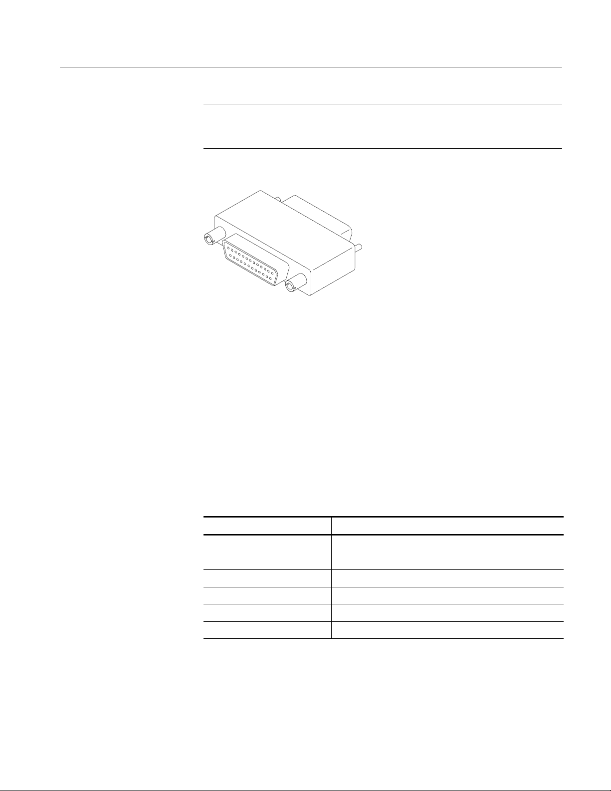
2. Install the Software Key on the rear panel Parallel port. MTS300 MPEG Test
System software applications will not run without the Software Key
installed; do not remove or misplace the Software Key.
To use the Parallel port with the Software Key installed, attach any parallel
port cables (such as a printer) directly to the Software Key. The Software
Key does not interfere with parallel communications.
1- 8
MTS300 MPEG Test System Hardware and Software Installation Technical Reference
Page 27
Hardware Installation
NOTE. To run MTS300 MPEG Test System applications, the Software Key must
be on the computer Parallel port. If you return the test system to a Tektronix
Service Center for upgrade or repair, include the Software Key.
Figure 1- 3: Software Key
Supplying Power
The MTS300 MPEG Test System platform is designed to operate from a
single-phase power source having one of its current carrying conductors at or
near earth ground (the neutral conductor). Power sources that have both current
carrying conductors live with respect to ground, such as phase-to-phase or
multiphase systems, are not recommended. A protective ground connection, by
way of the grounding conductor in the power cord, is essential for safe operation.
The electrical operating requirements are listed in Table 1--7.
Table 1- 7: Electrical operating requirements
Requirement Specification
Source Voltage 100 VAC to 240 VAC
47 Hz to 63 Hz
Fuse Rating 10 A Fast / 250 V
Maximum Power Consumption 170 Watts typical
Inrush Surge Current 36 Amps maximum
Power Factor Correction Yes
MTS300 MPEG Test System Hardware and Software Installation Technical Reference
1- 9
Page 28
Hardware Installation
After you have installed the MTS300 system and completed making the signal,
network, and peripheral connections, plug the power cord into the mains. See
Figure 1--1 for location of power connector.
CAUTION. Do not supply power to the instrument until all connections have been
made.
WARNING. The test system is designed for connection to an earth-grounded AC
outlet. To avoid risk of electrical shock or equipment damage, do not disable the
grounding plug.
Mains Voltage Range. You can power the test system computer and monitor from
mains that supply between 100 VAC and 240 VAC without setting a voltage
selection switch.
Mains Frequency. The test system computer and monitor operate on either 50 Hz
or 60 Hz line frequencies.
CAUTION. To prevent damage, protect the system computer from power fluctuations and temporary interruptions with a regulating noninterruptible power
supply. This device protects the hardware from damage caused by power surges
and voltage spikes. In addition, it allows the system to operate temporarily
during a power failure.
Power Cord Options. Unless a specific power cord option is ordered, the system
computer and monitor come standard with a power cord for North American
60 Hz, 120 VAC supplies. Table 1--2 on page 1--3 lists the power cord options.
1- 10
MTS300 MPEG Test System Hardware and Software Installation Technical Reference
Page 29

Connecting MTS300 System I/O Ports
Figure 1--4 through Figure 1--11 show the available input and output (I/O)
connector configurations on the MTS300 rear panel. For I/O port specifications,
refer to the Specifications section beginning on page 3-1. Use the I/O ports that
best suit your operating environment and signal sources. A description of each
connector type follows.
Hardware Installation
Input
Trigger Input
Clock Input
Output to Other
Equipment
You must provide input to the MTS300 system to monitor an MPEG-2, DVB, or
ATSC bit stream. The MTS300 system I/O ports can be ASI serial, SPI (LVDS),
DHEI (GI-Digicypher), or SSI (SMPTE310M). To change the configuration,
refer to Configuration Client Reference in the MTS300 MPEG Test System
Real-Time Analysis User Manual.
The trigger input accepts a TTL level (0 to +5 V) signal you can use to control
capture of the MTS300 system input stream to the system disks. You can
configure the system to start/stop data capture on either the rising edge (low to
high transition) or the falling edge (high to low transition) of the trigger signal.
Refer to the MTS300 MPEG Test System Real-Time Analysis User Manual for
further information on capturing transport stream inputs.
Each output port has a corresponding clock input which can be used to clock the
transport stream output when using Stream Player. The clock rate is at the byte
rate of the transport stream for the ASI/M2S and SPI (LVDS) formats. The clock
rate is at the bit rate of the transport stream for the SMPTE310M (SSI) and
DHEI (GI Digicypher) formats.
Applications generating an output will do so on the I/O port to which the
application has been assigned. Applications requiring an input have an output
activation option that will loop-through the input signal to the output connector
on the assigned I/O port.
When an output port is used to generate signals using the Stream Player or
OpenMux applications, the corresponding input port cannot be used.
MTS300 MPEG Test System Hardware and Software Installation Technical Reference
1- 11
Page 30

Hardware Installation
ASI/M2S I/O
Figure 1- 4: Rear-panel configuration with one ASI/M2S (Option AS) interface installed
ASI/M2S I/O ASI/M2S I/O
Figure 1- 5: Rear-panel configuration with two ASI/M2S (Option AS) interfaces installed
1- 12
MTS300 MPEG Test System Hardware and Software Installation Technical Reference
Page 31

Hardware Installation
ASI/M2S I/O SSI (SMPTE310M) I/O
Figure 1- 6: Rear-panel configuration with ASI/M2S (Option AS) and SSI (Option SS) interfaces installed
ASI/M2S I/O
DHEI (GI-Digicypher) I/O
Figure 1- 7: Rear-panel configuration with ASI/M2S (Option AS) and DHEI (Option DE) interfaces installed
MTS300 MPEG Test System Hardware and Software Installation Technical Reference
1- 13
Page 32

Hardware Installation
ASI I/O SPI (LVDS) I/O
Figure 1- 8: Rear-panel configuration with ASI/M2S (Option AS) and SPI (Option LV) interfaces installed
SSI (SMPTE310M) I/O
Figure 1- 9: Rear-panel configuration with one SSI (Option SS) interface installed
1- 14
MTS300 MPEG Test System Hardware and Software Installation Technical Reference
Page 33

Hardware Installation
SSI (SMPTE310M) I/OSSI (SMPTE310M) I/O
Figure 1- 10: Rear-panel configuration with two SSI (Option SS) interfaces installed
SSI (SMPTE310M) I/O
ASI/M2S I/O
Figure 1- 11: Rear -panel configuration with SSI (Option SS) and ASI/M2S (MTS3FAS) interfaces installed
MTS300 MPEG Test System Hardware and Software Installation Technical Reference
1- 15
Page 34

Hardware Installation
Repackaging for Shipment
Your instrument was originally shipped by Tektronix in a carton with packaging
components designed to protect the instrument from damage during shipment. If
you need to ship the instrument to another location, it is strongly recommended
that you use the original shipping carton and packaging components to provide
adequate protection during shipment.
CAUTION. To prevent the loss of your instrument’s warranties, Tektronix strongly
recommends that you use your original shipping carton (one that is in good
condition) when you ship the instrument to another location or when you return
the instrument to a Tektronix service center for repair.
Tektronix cannot honor the instrument’s warranties if the instrument arrives at
the service center damaged and it was not shipped in its original carton or in a
replacement carton (and its supporting packaging material) purchased from
Tektronix. If you lose your original packaging material, contact your Tektronix
representative to obtain replacement packaging.
Packaging Inspection
When preparing to ship your instrument to another location, it is important to
inspect your existing packaging materials for condition, missing components and
vintage.
H If the condition of your existing packaging materials is poor, or if you are
missing some of the components, it is strongly recommended that you order
a new packaging kit. The new packaging kit will accommodate both the
portable and the rackmount versions of the instrument cabinet.
If your existing packaging materials are in good condition, compare them
against Figures 1--12 and 1--13 to determine which packaging procedure to
use. Use the procedure associated with your existing packaging materials.
H The configuration (vintage) of the packaging materials is important to note.
Replacement components for the old-design packaging materials are no
longer available. Also, the components of the new and old designs are not
interchangeable. If your packaging materials are of the old design, and
require any replacement components, you must order a new packaging kit.
If your instrument was originally shipped in the older design packaging and
you have converted the cabinet from portable to rackmount configuration,
use the new design packaging which contained the rackmount conversion kit,
or order a new design shipping kit.
1- 16
MTS300 MPEG Test System Hardware and Software Installation Technical Reference
Page 35

Hardware Installation
Replacement Packaging
Materials
New packaging materials are available from Tektronix. To obtain these items,
contact your nearest Tektronix representative.
The replacement packaging kit, Tektronix part number 065-0651-XX, includes
all of the packaging material shown in Figure 1--12. Each packaging component
in the illustration has an index number, which corresponds to reference numbers
in the packaging procedure.
1
2
3
4
Note: The keyboard, mouse, manual, and their boxes do not need
to be returned with the instrument for servicing. A protective bag for
the instrument is included in the packaging kit, but is not shown.
Figure 1- 12: Repackaging the instrument (new packaging)
MTS300 MPEG Test System Hardware and Software Installation Technical Reference
1- 17
Page 36

Hardware Installation
Repackaging Procedure
(New Design)
When the instrument is shipped, it is important to package it well to protect the
instrument. Figure 1--12 shows how to repackage the instrument for shipment
using the new packaging materials. It is not necessary to return the accessories
received with the instrument when returning the instrument for repair.
NOTE. The packaging materials illustrated in Figure 1--12 will accommodate
both the portable and the rackmount versions of the instrument cabinet.
1. If the instrument is to be shipped to a Tektronix field office for repair, attach
a tag to the instrument showing the following:
H Owner’s name and address
H Instrument serial number
H Description of the problem(s) encountered and/or service required.
2. Place the protective front cover on the front of the instrument.
3. Place the instrument in the protective bag. The bag prevents dust moisture,
or other debris from entering the cabinet.
4. Fold the top of the bag neatly over the top of the instrument to make it as flat
as possible and seal with packing tape.
5. Place the front cushion (3) over the front of the instrument.
6. Place the rear cushion (2) over the rear of the instrument.
7. Carefully lift the instrument with front and rear cushions attached and lower
into the shipping box (4) as indicated by Figure 1--12.
8. Position the tray (1) into the top of the box, pressing the tray down until it
rests on the tops of the front and rear cushions.
NOTE. To ensure packaging integrity and product safety, the tray (1) must be
installed regardless if any accessories are being included in the package.
9. If you are shipping the accessories, arrange the accessories in the tray.
10. Close and tape the shipping box.
11. Attach the appropriate shipping documents needed to ship the instrument to
its destination.
1- 18
MTS300 MPEG Test System Hardware and Software Installation Technical Reference
Page 37

Hardware Installation
Repackaging Procedure
(Old Design)
If your instrument was shipped in the older packaging materials as shown in
Figure 1--13, inspect your existing packaging materials to make sure they are
complete and in good condition as described in Packaging Inspection on
page 1--16. If your existing earlier packaging materials are in good condition,
follow the procedure below to repackage your instrument for shipment.
When the instrument is shipped, it is important to package it well to protect the
instrument. Figure 1--13 shows how to repackage the instrument for shipment
using the old packaging materials. It is not necessary to return the accessories
received with the instrument when returning the instrument for repair.
NOTE. The packaging materials illustrated in Figure 1--13 will accommodate
only the portable version of the instrument cabinet.
1
2
3
4
5
Note: The keyboard, mouse, and
manual boxes do not need to be
returned with the instrument for
servicing.
Figure 1- 13: Repackaging the instrument (old packaging)
MTS300 MPEG Test System Hardware and Software Installation Technical Reference
1- 19
Page 38

Hardware Installation
The inner shipping box, pads, and protective bag provide the necessary
protection to allow the shipping materials of the outer shipping box to correctly
support the product for shipment. Pack the inner shipping box as follows:
1. If an instrument is to be shipped to a Tektronix field office for repair, attach a
tag to the instrument showing the following:
H Owner’s name and address
H Instrument serial number
H Description of the problem(s) encountered and/or service required.
2. If you have the original packaging material, start by placing one of the
spacer pads in the bottom of the inner box (3). Position the side of the pad
with the smaller, square holes against the side of the box as shown in
Figure 1--14.
Outside edge of box
Bottom spacer pad
Spacer pad
positioned inside the
bottom of the box
1- 20
Figure 1- 14: Placement of bottom spacer pad in inner shipping box
MTS300 MPEG Test System Hardware and Software Installation Technical Reference
Page 39

Hardware Installation
3. Place the protective front cover on the front of the instrument.
4. Place the instrument in the protective bag. The bag prevents dust, moisture,
or other debris from entering the cabinet.
5. Fold the top of the bag neatly over the top of the instrument to make it as flat
as possible and seal with packing tape.
6. Place the bagged instrument in the inner shipping box. The small feet on the
bottom of the cabinet go in the square holes in the spacing pad and the larger
feet near the front of the instrument go in the larger rectangular holes. The
bezel end of the cabinet fits over the edge of the spacer pad.
7. Place the other spacer pad on top of the instrument. Place the side with the
small square holes against the side of the box. The protective front cover on
the bezel of the instrument is not covered by the top spacer pad.
8. Close and tape the inner shipping box (3).
9. Place one of the support inserts (4) in the bottom of the outer shipping box,
film side up as shown in Figure 1--13.
10. Place the sealed inner shipping box (3) in the center of the bottom support
insert in the outer shipping box (4).
11. Put the second support insert (2) over the inner shipping box, film side
down.
NOTE. It may be necessary to pre-stretch the film in the support inserts by
pushing down firmly several times on the top support insert.
12. Place the top tray (1) in the box. If you are not shipping accessories with the
instrument, close and tape the outer shipping box (5).
13. When shipping the accessories, place the two accessory trays in the top tray,
then arrange the accessories in the trays.
14. Close and tape the outer shipping box (5).
15. Attach the appropriate shipping documents needed to ship the instrument to
its destination.
MTS300 MPEG Test System Hardware and Software Installation Technical Reference
1- 21
Page 40

Hardware Installation
1- 22
MTS300 MPEG Test System Hardware and Software Installation Technical Reference
Page 41

First Time Operation
Page 42

Page 43

First Time Operation
This section contains information for first-time operators about starting and
shutting down the MTS300 system. A functional check procedure is provided to
verify basic instrument operation.
Starting the MTS300 System
Perform the following procedure to power on the MTS300 system:
1. Connect the power cord to the rear-panel power connector.
2. Press the On/Stby switch to power on the instrument. Figure 2--1 shows the
switch location.
MPEG Test System
On/Stby switch
Figure 2- 1: On/Stby switch
3. The Windows NT initialization process takes up to two minutes. Under
normal circumstances, no action is required until the Begin Logon message
appears.
4. When the Begin Logon message appears, simultaneously press the
CTRL + ALT + Delete keys to open the Logon Information dialog box.
MTS300 MPEG Test System Hardware and Software Installation Technical Reference
2- 1
Page 44

First Time Operation
Logging On
Starting MTS300 System
Applications
The MTS300 system uses the Windows NT auto-logon feature by default. The
default user name and password are Administrator and MPEG2, respectively.
You do not need to enter a user name or password to log on to the MTS300 the
first time.
Changing the Passwords. After you log on to the MTS300 system the first time
(or at any subsequent time), you can change the password for that user name, or
create new profiles for different users of the test system. Refer to the Windows NT online help for instructions.
Refer to Setting, Resetting, and Disabling Auto Logon on page 4--11 if you want
to disable automatic logon to Windows NT when you power-on the instrument.
CAUTION. To prevent the loss of data, if you change the default user names and
passwords, secure the new names in a safe place. If you forget your user-defined
user names and passwords and cannot logon to the MTS300 system, you will
have to reinstall the operating system software which will result in the loss of all
data on the hard drives of the MTS300 system.
After you have logged on, the Tektronix MPEG Test System program group
window appears as shown below. Double-click the appropriate application icon
to launch the desired application.
NOTE. The example below shows an MTS300 system program group with most of
the available options installed. Depending on which options you ordered, your
program group may not contain all application icons.
2- 2
MTS300 MPEG Test System Hardware and Software Installation Technical Reference
Page 45

First Time Operation
General License
Password
Enabling the OpenMux
Demonstration Period
When you first receive your MTS300 system, the General License password is
already installed. You will have to reenter the General License password only
when you restore the MTS300 operating system software.
Refer to Software Repair and Recovery on page 4--1 for information about
repairing system software or resetting system parameters. The procedure for
entering the General License password starts on page 4--29.
If you ordered Option OM with your MTS300 system, the OpenMux server
starts automatically with the rest of the MPEG Analysis Services, and you can
ignore this section. If you did not order Option OM, you can enable the
OpenMux server and client application for a thirty day demonstration period at
any time using the following procedure. Performing this procedure will also
clear the Failure in socket connection error message that appears when you try to
connect the OpenMux server to the local Server Manager without a valid license
password.
NOTE. Once the demonstration period begins, it lasts for 30 consecutive days
and then ends. You cannot start, stop, and restart the demonstration period.
Also note that the demonstration license enables all MTS300 applications for the
same thirty day demonstration period. So, you cannot enable one application for
a thirty day period and then enable other applications for a subsequent thirty
day period.
1. Double-click the OpenMux Mode.exe file located in the C:\MTS300\Bin
directory.
2. Click the Start OpenMux server automatically option and then click OK
as shown below.
3. Reboot the test system and enter the demonstration license password that
shipped with the MTS300 test system when prompted to do so.
MTS300 MPEG Test System Hardware and Software Installation Technical Reference
2- 3
Page 46

First Time Operation
Disabling the OpenMux
Server Startup
If you enabled the demonstration period for the OpenMux server and you want to
remove the message that appears at startup after the demonstration period is over,
use the following procedure:
1. Double-click the OpenMux Mode.exe file located in the C:\MTS300\Bin
directory.
2. Clear the Start OpenMux server automatically option and then click OK.
3. Reboot the test system.
Shutting Down the MTS300 System
This section contains information about how to exit MTS300 system applications and how to shutdown the MTS300 system.
Exiting MTS300 System
Applications
To exit an MTS300 system application, select Exit or Qu it from the File menu
or click the close button in the upper-right corner of the application window.
Close
button
Shutting Down the
MTS300 System
There are three methods to shut down the MTS300 system: standard power
down, soft power down, and hard power down. For the standard and hard power
down methods, you should exit all MTS300 applications before shutting the
instrument down.
CAUTION. To prevent data loss, it is recommended that you exit all open MTS300
applications before powering down the instrument. Some applications will
prompt you to save unsaved data before exiting. If you do not close all MTS300
applications before exiting Windows NT, you may lose data.
2- 4
MTS300 MPEG Test System Hardware and Software Installation Technical Reference
Page 47

First Time Operation
Standard Power Down. To power down the MTS300 system during normal
instrument operations, perform the following standard Windows NT power down
procedure:
1. Exit all open MTS300 applications.
CAUTION. To prevent data loss, exit all open MTS300 applications before
powering down the instrument. Some applications will prompt you to save
unsaved data before exiting.
2. After the MTS300 applications are closed, shut down Windows NT by
selecting Shut Down from the Windows NT Start menu as shown below.
CAUTION. To prevent data loss and possible system problems during subsequent
Windows NT initializations, always exit Windows NT before you power down the
MTS300 system. Wait until the message “It is now safe to turn off your computer” appears before you press the On/Stby switch.
3. Select Shut down the computer? in the resulting Shut Down Windows
dialog box shown below, and then click Yes .
4. After the Shutdown Computer window appears with the message “It is now
safe to turn off your computer,” press the On/Stby switch to put the MTS300
system into standby mode.
5. After the MTS300 system goes into standby mode, you can restart the
instrument by pressing the On/Stby switch.
6. To completely remove power to the instrument, disconnect the power cord at
the rear panel.
MTS300 MPEG Test System Hardware and Software Installation Technical Reference
2- 5
Page 48

First Time Operation
Soft Power Down. The MTS300 system is shipped from the factory with a soft
power-down capability enabled. The soft power-down capability allows you to
directly exit Windows NT without closing the MTS300 applications first. Using
this technique, the MTS300 system will automatically close all open applications
and put the instrument into standby mode.
To soft power-down the MTS300 system, perform the following steps:
1. Press and release the On/Stby switch to initiate the soft power-down
process. Some applications will prompt you to save unsaved data before
exiting.
2. After the MTS300 system goes into standby mode, you can restart the
instrument by pressing the On/Stby switch.
3. To completely remove power to the instrument, disconnect the power cord at
the rear panel.
Hard Power Down. You can use the hard power-down capability to immediately
power-down the MTS300 system in an emergency situation such as fire.
CAUTION. To prevent data loss and the corruption or deletion of application and
system files, perform this procedure only if all other attempts to shut down the
MTS300 system have failed.
Using this hard power down procedure will likely cause file problems. When you
use this method to power down the MTS300 system, the next time the instrument
is powered on, the operating system will use the Scan Disk utility to perform a
check for missing or corrupt files. You may be prompted to reinstall the
operating system or application software.
To hard power-down the MTS300 system, perform the following steps:
1. Press and hold the On/Stby button for about 3 or 4 seconds.
2. After the MTS300 system goes into standby mode, you can restart the
instrument by pressing the On/Stby switch. Read the power-on messages for
information about possible missing or corrupted files.
3. To completely remove power to the instrument, disconnect the power cord at
the rear panel.
2- 6
MTS300 MPEG Test System Hardware and Software Installation Technical Reference
Page 49

Functional Check
You can verify the performance of the MTS300 test system to the published
specifications by performing the following procedures:
H 10 MHz Reference Clock
H I/O System
H MPEG-2 Software Components
H TMCC Software Components
NOTE.The10 MHz Reference Clock procedure requires a qualified technician to
remove the instrument cabinet and to apply a probe to a test point on the PIA+
circuit board. If the reference clock is out of tolerance, a procedure is provided to
instruct the technician how to remove the PIA+ board and to adjust the reference
clock. This test must be performed in a static-free workspace.
If you do not have access to a qualified technician or to a static-free work space,
you can perform only the last three procedures. If the instrument passes the last
three procedures, you can have a high level of confidence that all of the major
functions of the instrument are functioning properly.
10 MHz Reference Clock
CAUTION. Be sure to read the General Safety and Service Safety summaries at
the beginning of this manual before you perform this procedure.
T o prevent potential damage to the MTS300 test system, only perform this
procedure to verify the accuracy of the 10 MHz reference clock if you are a
qualified technician and are working in a static-free work space.
Recommended Tools
MTS300 MPEG Test System Hardware and Software Installation Technical Reference
You will need the following tools to verify the 10 MHz reference clock:
H An anti-static wrist strap for safe handling of assemblies containing static
sensitive devices
H A screwdriver with T10, T15, and T20 Torx tips to remove the cabinet cover
and the module mounting screws.
2- 7
Page 50

Functional Check
H A 1/4 inch or larger flat blade screwdriver .
H An 8 inch adjustable wrench or appropriate size open-end wrench (an aid for
cabinet removal).
H A digital frequency counter to measure the 10 MHz clock. Accuracy: ᐔ2Hz
at 10 MHz. Example: Tegam DC5010 with an external frequency reference.
NOTE. Some frequency counters require an external signal reference to attain the
required accuracy.
H A 10X probe for use with the frequency counter. Example: Tektronix
P6109B.
H If you need to adjust the 10 MHz reference clock, you will need a small,
narrow adjustment tool.
Removing the Cabinet
You will remove the instrument cabinet to access most of the mainframe
modules and the test system application modules. Use the following procedure to
remove the cabinet (portable or rackmount):
1. Put on a static grounding wrist strap.
2. Before removing the cabinet, shut down the test system and unplug the
power cord.
3. Disconnect any cables connected to the rear panel connectors of the test
system. Note their locations for reinstallation.
4. Put the protective front cover on the test system and sit the cabinet upright
on the working surface with the rear panel facing up.
NOTE. If your MTS300 system is configured as a rackmount instrument, ignore
step 5. There is no handle installed. Continue with the step 6.
5. Remove the two screws from the handle on the right side of the instrument
(see Figure 2--2). These screws attach to posts mounted on the power supply
module.
6. Remove the screws from the four feet on the rear of the instrument (see
Figure 2--3).
2- 8
MTS300 MPEG Test System Hardware and Software Installation Technical Reference
Page 51

Handle mounting screws
(not on rackmount instruments)
Functional Check
Figure 2- 2: Removing t he cabinet handle
Rear feet screws (4)
Figure 2- 3: Removing t he cabinet feet
MTS300 MPEG Test System Hardware and Software Installation Technical Reference
2- 9
Page 52

Functional Check
7. Use either an adjustable wrench or appropriate size open-end wrench as a
lever to pry the cabinet loose from the chassis. Loosen each side alternately
until the cabinet is released from the EMI gasket.
8. Slide the cabinet up and off the chassis.
CAUTION. Use care when touching the EMI shielding strips around the front of
the chassis. The fingers of the strip are easily bent and any protruding sharp
edges become a potential cutting hazard when you handle the chassis to position
it during the remaining remove and replace procedures.
Remove the Circuit Board
Retaining Plate
Remove the circuit board retaining plate (see Figure 2--4).
Screws (7)
Circuit board
retaining plate
2- 10
Figure 2- 4: Removing t he circuit board retaining plate
MTS300 MPEG Test System Hardware and Software Installation Technical Reference
Page 53

Functional Check
Check the Clock
Frequency
Perform the following steps to check the 10 MHz reference clock frequency.
NOTE. Be sure that the counter accuracy is within ᐔ2Hzat10MHz.
1. Reconnect power to the instrument and reboot the test system.
2. Allow the instrument to warm up for 20 minutes.
3. Connect a 10X probe to the input of the frequency counter. Set the frequency
counter for AC coupling and high impedance input (1 MΩ).
4. Touch the 10X probe to the 10 MHz clock output on the PIA+ board (be sure
that the probe ground clip is connected to a suitable point). See Figure 2--5.
PIA + circuit board in
instrument card cage
To rear of
instrument
10 MHZ clock
test point
Figure 2- 5: Location of 10 MHz clock test point
5. Adjust the frequency counter as necessary to trigger on the clock signal.
6. Check that the clock frequency is within 1.0/ppm or ᐔ10Hz of 10 MHz.
If the clock frequency is within ᐔ10 Hz of 10 MHz, proceed to I/O System on
page 2--16. Otherwise perform the procedure in Adjust the Clock Frequency
startingonpage2--12.
MTS300 MPEG Test System Hardware and Software Installation Technical Reference
2- 11
Page 54

Functional Check
Adjust the Clock
Frequency
Perform the following steps to adjust the frequency of the 10 MHz reference
clock.
NOTE. Only perform this procedure if the 10 MHz reference clock was measured
to be out of tolerance in the preceding procedure.
1. Note the measured clock frequency from step 6 on page 2--11.
2. Power down the MTS300 test system and remove the power cord.
NOTE. To adjust the reference clock, you must remove the PIA+ module from the
instrument. If there is an optional interface installed on the PIA+ module (two
interfaces installed), you will also have to remove the second interface with the
PIA+ module.
3. Remove the retaining screws from the top and bottom of the PIA+ module
(see Figure 2--6) and from the top and bottom of the brackets for any
optional interfaces that may be installed.
4. Loosen the retaining screws from the top and bottom of any brackets
adjacent to the module brackets you are removing.
5. Carefully pull up on the PIA+ board to loosen it from the backplane module
connectors. You may have to alternate lifting up on the front and the rear of
the board to work it loose from the connectors and the card bay.
6. When the PIA+ board is loose from the connector, lift the module out of the
module bay.
7. Place the removed PIA+ board on a static-free work surface.
2- 12
MTS300 MPEG Test System Hardware and Software Installation Technical Reference
Page 55

Top view
PIA+ module
Functional Check
Loosen
this
screw
Remove
screws for
PIA+ module
Loosen
this
screw
Rear view
Remove screws
for PIA+ module
Figure 2- 6: Removing t he PIA+ module
MTS300 MPEG Test System Hardware and Software Installation Technical Reference
2- 13
Page 56

Functional Check
8. Locate R500 (a 10 turn pot) on the PIA+ board (see Figure 2--7). R500 is
located just behind J10 next to Y501.
NOTE. It is possible to adjust R500 without removing the Mezzanine board from
the PIA+ board if you use caution. If you need to remove the Mezzanine board to
make this adjustment, remove the three screws shown in Figure 2--7, and then
carefully remove the Mezzanine board from the three connectors on the PIA+
board (J10, J501, and J502).
Screws (3)
Mezzanine
board
PIA+ board with a single
ASI/M2S interface installed
Note: Your PIA+ board may
have a single SSI interface
installed or may have two
interfaces installed.
J10
Adjustment
tool
Figure 2- 7: Adjusting the 10 MHz reference clock
R500
Y501
2- 14
MTS300 MPEG Test System Hardware and Software Installation Technical Reference
Page 57

Functional Check
9. Adjust R500 using the values in Table 2--1 and the measured clock frequency
fromstep6onpage2--11.
Table 2- 1: Adjustment table for 10 MHz reference clock
Rotation required to
Measured frequency Error Error in PPM
10.000984 MHz -- 1 6 H z --1.6 ppm 2 turns CCW
10.000988 MHz -- 1 2 H z --1.2 ppm 1.5 turns CCW
10.000992 MHz -- 8 H z --0.8 ppm 1.0 turn CCW
10.000996 MHz -- 4 H z --0.4 ppm 0.5 turn CCW
10.000000 MHz 0Hz 0 ppm 0 turns
10.000004 MHz +4 Hz +0.4 ppm 0.5 turn CW
10.000008 MHz +8 Hz +0.8 ppm 1.0 turn CW
10.000012 MHz +12 Hz +1.2 ppm 1.5 turns CW
10.000016 MHz +16 Hz +1.6 ppm 2.0 turns CW
1
One turn in the CW or CCW direction will change the frequency by 8 Hz or 0.8 ppm
correct (CW or CCW)
1
10. After you have adjusted R500, reinstall the PIA+ board by inserting the
module into the module bay at the correct slot position.
11. Carefully align the PIA+ board edge connector with the backplane connectors.
12. Apply firm pressure to completely seat the PIA+ board in the connectors.
13. Replace the retaining screws which secure the PIA+ board in the card bay
(the ones you remove in step 3 on page 2--12).
14. Torque the screws to 8 in-lbs (including the ones you loosened in step 4 on
page 2--12.
15. Reconnect power to the MTS300 test system and reboot the instrument.
16. Allow the instrument to warm up for 20 minutes.
17. Perform the procedure in Check the Clock Frequency on page 2--11 and
repeat this clock adjustment procedure as necessary until the measured clock
frequency is within tolerance.
MTS300 MPEG Test System Hardware and Software Installation Technical Reference
2- 15
Page 58

Functional Check
Reinstall the Circuit Board
Retaining Plate
Reinstall the Instrument
Cabinet
I/O System
Recommended Tools
Power down the instrument, remove the power cord, and then install the circuit
board retaining plate (see Figure 2--4 on page 2--10).
Reinstall the instrument cabinet by performing the procedure in Removing the
Cabinet startingonpage2--8inreverseorder.
Use the following procedure to verify the hardware components of the MTS300
system.
You will need the following tools to perform this I/O system test:
H Interface cables for each type of I/O port installed in the MTS300 system
(75 Ω BNC cables for ASI/M2S and SSI (SMPTE310M) interfaces, and
appropriate cables if you have a DHEI (GI Digicypher) or SPI (LVDS)
interface installed)
H 50 Ω BNC cable (for use with the signal generator)
Initial Setup
H BNC T-connector
H Digital frequency counter. Accuracy: ᐔ2Hzat10MHz.
H Signal generator with 50 Ω output of TTL-level signals
1. Connect all the inputs to the corresponding outputs as shown in Figure 2--8.
(Your rear-panel configuration may differ from the illustration.) For the BNC
connectors, use 75 Ω cables.
2. PowerupandlogontotheMTS300system.
3. Once you have correctly logged on, double-click the Tektronix MPEG Test
System program group icon on the desktop.
4. The Tektronix MPEG program group window similar to that shown in
Figure 2--9 on page 2--18 will be displayed.
2- 16
MTS300 MPEG Test System Hardware and Software Installation Technical Reference
Page 59

Functional Check
Power
RS-232
COM Port 1
ASI I/O
Figure 2- 8: Typical initial equipment setup
SPI (LVDS)
I/O
SVGA
Ethernet
KeyboardSCSI
Printer
Mouse
Verify the Performance of
Hardware Components
Each test system is shipped with a Hardware Diagnostic application that verifies
the performance of the hardware components of the MTS300 system. Using this
tool, you check the following parameters:
H Board access
H Process paths
H Stream paths
H I/O parameters
H External connections
H Trigger and Clock
MTS300 MPEG Test System Hardware and Software Installation Technical Reference
2- 17
Page 60

Functional Check
Diagnostic Self Test
1. Start the Hardware Diagnostic by double-clicking the Hardware Diagnostic
icon in the Tektronix MPEG Test System program window.
Figure 2- 9: Tektronix MPEG Test System program window
2. Initially, the Hardware Diagnostic window is blank (see Figure 2--10). To
start the diagnostic, you must first connect to the local Server Manager.
2- 18
Figure 2- 10: Connect to local Server Manager
MTS300 MPEG Test System Hardware and Software Installation Technical Reference
Page 61

Functional Check
3. Select all of the tests to be performed by clicking all of the appropriate boxes
under Test Name as shown in Figure 2--11.
Figure 2- 11: Start the testing routine
4. Select Display Report View, and then click Start.
5. The following message is displayed. Click Yes to begin the routine.
Figure 2- 12: Begin the self test routine
MTS300 MPEG Test System Hardware and Software Installation Technical Reference
2- 19
Page 62

Functional Check
6. As the routine continues, the display records the results as shown in
Figure 2--13.
Figure 2- 13: Window showing sample test results summary
The Diagnostic Self Test Configuration area indicates which tests are being
performed and the progress of each test:
H A yellow LED icon indicates the test is in process.
H A green LED icon indicates that the test is completed and passed.
H A red LED icon indicates that the test failed, and the self test stops.
The Test Results Summary area displays a summary of each test checked in the
test control area. This section updates with a summary of the test results when all
tests for that set of diagnostics has been performed.
The Report View area records details about each test as it is being performed.
2- 20
MTS300 MPEG Test System Hardware and Software Installation Technical Reference
Page 63

Functional Check
7. If the corresponding input and output connections have not been made as
shown in Figure 2--8 on page 2--17, the routine will stop at the beginning of
the External Connection test and the following message will appear.
Figure 2- 14: Message box with connection requirements
8. Connect the cabling as prompted by the message box. To continue the
routine click Retry once the connection has been made.
NOTE. If you connect all the I/O’s at this time each I/O test will be performed
without interruption. If you connect only one, then the message will appear at
the conclusion of each test. Move the cable to the next I/O as prompted in the
message box.
MTS300 MPEG Test System Hardware and Software Installation Technical Reference
2- 21
Page 64

Functional Check
Trigger and Clock
1. Connect the output from the signal generator to the I/O #1 Trigger input on
the rear panel of the MTS300 as shown in Figure 2--15. Use a 50 Ω BNC
coaxial cable to make the connection.
NOTE. All input signals to the MTS300 must be at TTL levels and the trigger and
clock inputs must come from 50 Ω sources.
2. Follow the on-screen procedure.
Signal generator
MTS300 Analyzer
50 Ω coaxial cable
Rear panel
I/O #1 TRIG IN
Figure 2- 15: Connections f or trigger test
3. Connect the output from the signal generator to the I/O #1 Clock input on
the rear panel of the MTS300 and to a frequency counter as shown in
Figure 2--16. Use a BNC T-connector and a 50 Ω BNC coaxial cable to make
the connection.
4. Follow the on-screen procedure.
Signal generator
MTS300 Analyzer
Rear panel
I/O #1 CLK IN
50 Ω coaxial cable
T-connector
Frequency Counter
IN
Figure 2- 16: Connections f or clock test
5. This concludes the Hardware Diagnostics. Click Quit to end the routine.
2- 22
MTS300 MPEG Test System Hardware and Software Installation Technical Reference
Page 65

MPEG-2 Software Components
Use this procedure to verify the operation of the MPEG-2 software components
of the MTS300 system.
Functional Check
Monitoring an Input
1. Connect the input of I/O #1 to the output of I/O #2 as shown in Figure 2--17.
Use a 75 Ω BNC cable to make the connection.
ASI I/O
Figure 2- 17: ASI cabling
2. Start the Master Client by double-clicking the Master Client icon in the
Tektronix MPEG Test System program window.
MTS300 MPEG Test System Hardware and Software Installation Technical Reference
2- 23
Page 66

Functional Check
3. Initially, the Master Client window is blank as shown in Figure 2--18. To
start monitoring an input, you must first connect to the local Server Manager.
Figure 2- 18: Initial Master Client application window
4. Connect to the local Server Manager by selecting Master | Connect locally.
Figure 2- 19: Connecting t o the local Server Manager
2- 24
MTS300 MPEG Test System Hardware and Software Installation Technical Reference
Page 67

Functional Check
5. Once you have connected to the local Server Manager, the Master Client
appears as in Figure 2--20 with the I/O ports labeled Free in the Port
Manager panel. You are now ready to assign the I/O ports to an Analysis
Server and application.
Figure 2- 20: Master Client window showing no assigned ports
MTS300 MPEG Test System Hardware and Software Installation Technical Reference
2- 25
Page 68

Functional Check
6. Select I/O #1 in the Port Manager panel, right click, and then select Assign
Server | Analysis Server from the shortcut menu.
Figure 2- 21: Port Manager panel showing Analysis Server selected
7. Select I/O #2 in the Port Manager panel, right click, and then select Assign
Server | Stream Player from the shortcut menu.
8. Select the Stream Player icon (I/O #2), right click, and then select Launch
Stream Player Client from the shortcut menu.
Figure 2- 22: Selecting Launch Stream Player Client
2- 26
MTS300 MPEG Test System Hardware and Software Installation Technical Reference
Page 69

Functional Check
9. Click the Browse button to select a transport stream file (*.trp) from the
MTS300 system hard drive.
Figure 2- 23: Stream Player Application window
MTS300 MPEG Test System Hardware and Software Installation Technical Reference
2- 27
Page 70

Functional Check
10. Browse to C:\MTS300\Cfg-Trp directory, and then highlight the Sample.trp
file. Click Open to load the file into the Stream Player.
Figure 2- 24: C:\MTS300\Cfg-Trp directory
11. Click the loop play button in the Stream Player window to begin
output of the transport stream. See also Figure 2--23.
12. Minimize the Stream Player application window.
2- 28
MTS300 MPEG Test System Hardware and Software Installation Technical Reference
Page 71

Functional Check
13. Select the Analysis Server icon (I/O #1), right click, and then select Start
Analysis from the shortcut menu.
Figure 2- 25: Starting transport stream analysis
14. After you start the analysis, an icon representing the service in the
Sample.trp file appears in the Services panel.
15. Select the Analysis Server icon, right-click, and then select Launch Expert
Client.
Figure 2- 26: Master Client in Analysis mode
MTS300 MPEG Test System Hardware and Software Installation Technical Reference
2- 29
Page 72

Functional Check
16. The Expert Client applications window opens. A typical display is shown in
Figure 2--27.
Figure 2- 27: Expert Client application window
17. Verify proper operation.
H Check that stream is acknowledged on Port 1.
H Confirm that the Program Allocation pie chart correctly shows one
program slice. (The PSI slice is too small to display.)
2- 30
MTS300 MPEG Test System Hardware and Software Installation Technical Reference
Page 73

Functional Check
2nd I/O Pair Setup
Procedure
1. Connect the output of I/O #1 to the input of I/O #2 as shown in Figure 2--28.
Use a 75 Ω BNC cable to make the connection.
ASI I/O
Figure 2- 28: Setup for testing second input
2. Exit the Expert Client application window.
Figure 2- 29: Exit Exper t Client application
3. Select I/O #1 in the Port Manager panel, right click, and then select Stop
Analysis from the shortcut menu.
4. Select I/O #1 in the Port Manager panel, right click, and then select Free I/O
from the shortcut menu.
5. Select I/O #2 in the Port Manager panel, right click, and then select Stop
generation from the shortcut menu.
MTS300 MPEG Test System Hardware and Software Installation Technical Reference
2- 31
Page 74

Functional Check
6. Exit the Stream Player Client application.
7. Select I/O #2 in the Port Manager panel, right click, and then select Free I/O
from the shortcut menu.
8. Select I/O #2 in the Port Manager panel, right click and then select Assign
Server | Analysis Server from the shortcut menu.
9. Select I/O #1 in the Port Manager panel, right click, and then select Assign
Server | Stream Player from the shortcut menu.
10. Select the Stream Player icon (I/O #1), right click, and then select Launch
Stream Player Client from the shortcut menu.
11. Click the Browse button to select a transport stream file (*.trp) from the
MTS300 system hard drive.
12. Browse to C:\MTS300\Cfg-Trp directory, and then highlight the Sample.trp
file. Click Open to load the file into the Stream Player.
13. Click the loop play
output of the transport stream.
14. Minimize the Stream Player application window.
15. Select the Analysis Server icon (I/O#2), right click, and then select S tart
Analysis from the shortcut menu.
16. After you start the analysis, an icon representing the service in the
Sample.trp file appears in the services panel.
17. Select the Analysis Server icon, right-click, and then select Launch Expert
Client.
button in the Stream Player window to begin
2- 32
MTS300 MPEG Test System Hardware and Software Installation Technical Reference
Page 75

Functional Check
18. The Expert Client applications window opens. A typical display is shown in
Figure 2--30.
Figure 2- 30: Expert Client application window
19. Verify proper operation:
H Check that stream is acknowledged on Port 2.
H Confirm that the Program Allocation pie chart correctly shows one
program slice.
If the analyzer successfully checks Sample.trp, functionality of the Analysis
Server, Stream Player Client and Stream Player Server, and the Expert Client is
confirmed. If the program allocation display does not show the pie chart or
report transmission rates correctly, switch the MTS300 system off and verify that
the PIA+ board is firmly seated in the PCI connector (slot 4 of the test system
card cage).
MTS300 MPEG Test System Hardware and Software Installation Technical Reference
2- 33
Page 76

Functional Check
3rd and 4th I/O Pair Setup
Procedure
1. If you have one of the I/O options installed, repeat the procedure that you
have just completed for the remaining I/O pairs (I/O #3 and I/O #4).
2. Connect the input to the corresponding output. Figure 2--31 shows the
connections using the rear panel with the SPI (LVDS) I/O option installed.
SPI (LVDS) I/O
(MTS3FLV)
Figure 2- 31: Rear panel connections for I/O #3 test procedure
If your MTS300 test system has software version 6.0 or higher and you are
operating in a TMCC environment, proceed with TMCC Softw are Components
beginning on page 2--35.
Otherwise, after a successful functional check, exit the Expert Client, Stream
Player, and Master Client and shut down the test system.
2- 34
MTS300 MPEG Test System Hardware and Software Installation Technical Reference
Page 77

TMCC Software Components
Perform the following steps only if you are operating the MTS300 system in a
TMCC environment.
Functional Check
Setup
Set TMCC Probes
1. Remove any signal cables that may still be connected to the MTS300 test
system rear panel from the previous procedure.
2. Connect a TMCC transport stream input signal to the I/O #1 input connector.
3. Select I/O #1 in the Port Manager panel, right click, and then select Assign
Server | Analysis Server from the shortcut menu.
1. Right-click the multiplex icon representing the TMCC transport stream input
(I/O #1), and then select TMCC Configuration Client from the submenu.
2. After the TMCC Configuration Client is displayed, click Analysis in the
navigation panel to open the Analysis configuration panel shown in
Figure 2--32.
3. Click the appropriate stream type for the type of TMCC transport stream you
are monitoring.
Figure 2- 32: Probes added in the TMCC Configuration Client
MTS300 MPEG Test System Hardware and Software Installation Technical Reference
2- 35
Page 78

Functional Check
4. Click Add All and notice that a number of probes are added to the List of
Probes selection box. See Figure 2--32.
The exact number of probes added will vary depending on whether you are
analyzing a TMCC basic or TMCC data stream. Data streams are analyzed
for the TMCC Update counter, whereas basic streams are not.
5. Click OK to save your changes, close the TMCC Configuration Client and
return to the Master Client.
Display the TMCC Expert
Client
6. Right-click the Multiplex icon for the input you just configured, and then
select TMCC Expert Client from the submenu.
7. Confirm that the TMCC Expert Client displays with data in the Slots,
Syntax, Dump, and Report view frames. See Figure 2--33.
8. Close the TMCC Expert Client and return to the Master Client.
Figure 2- 33: TMCC Expert Client
2- 36
MTS300 MPEG Test System Hardware and Software Installation Technical Reference
Page 79

Functional Check
Set ARIB Table Probes
Display the Section Rate
using the MPEG-2 Expert
Client
9. Right-click the Multiplex icon for the input you just configured, and then
select Configuration Client from the submenu.
10. In the Analysis Panel of the Configuration Client, select ISDB (this panel is
the default panel displayed when first starting the Configuration Client).
11. Select Rate | Section in the Navigation panel, and configure the Analysis
Server to check that the DCT is updated at least every .0001 seconds (the
rate, 0.1 Mbps, is a much higher rate than standard and will generate errors
from the Analysis Server.)
12. Apply your changes, restarting the Analysis Server when prompted, and then
exit the Configuration Client.
13. Confirm that errors are being reported for the input you just modified.
14. In the Master Client, click the Multiplex icon for the input you just
configured, and then right-click the TMCC Service icon displaying an error
and select Expert Client from the submenu.
15. When the Expert Client is displayed, locate a DCT icon in the Hierarchic
view.
16. Right-click the DCT icon select Section Rate from the submenu.
17. In the dialog box that is displayed, select one of the section numbers and
click OK.
18. Confirm that the client area of the Expert Client changes to show the section
rate analysis of the selected element.
19. Quit the Expert Client.
After a successful functional check, exit the Master Client and shut down the test
system.
MTS300 MPEG Test System Hardware and Software Installation Technical Reference
2- 37
Page 80

Functional Check
2- 38
MTS300 MPEG Test System Hardware and Software Installation Technical Reference
Page 81

Specifications
Page 82

Page 83

Specifications
This section lists the electrical, environmental, and physical specifications of the
MTS300 system. All specifications are guaranteed unless labeled typical. Typical
specifications are provided for your convenience and are not guaranteed.
Electrical characteristics apply to test systems operating within the environmental conditions specified in Table 3--10.
To verify performance of the test system, use the procedures in the performance
verification section of the MTS300 MPEG Test System Service Manual,an
optional accessory. Contact your Tekronix representative for ordering information.
Monitoring Characteristics
MPEG Characteristics:
H Supports MPEG--2, DVB, and ATSC protocols.
H Monitors PSI, SI, and PSIP table syntax and consistency errors.
Monitors transport and multiplex errors.
Monitors transport signal for sync loss.
H Generates MPEG transport streams (including ATSC and DVB--SI).
Data Rate Characteristics:
H Up to 140 Mbps with one input or 240 Mbps total using 2 to 4 inputs.
For example, Port 1 can run at 100 Mbps while port 2 is running at
140 Mbps for a total of 240 Mbps.
Number of Inputs:
H Standard Inputs: Two ASI/M2S input/output pairs
H Optional inputs: Two SPI (LVDS parallel), two SMPTE310M (SSI), or two
DHEI (GI-Digicypher) input/output pairs.
MTS300 MPEG Test System Hardware and Software Installation Technical Reference
3- 1
Page 84

Specifications
Interface Platform Characteristics
Table 3- 1: Platform characteristics
Characteristic Description Supplemental information
Operating system Windows NT 4.0 (Service pack 6)
Disk space System: 10 GB
MPEG Storage: 27 GB
COM Port RS-232
Ethernet 10/100-base T; RJ45
Mouse Mini DIN
Keyboard Mini DIN
SVGA 15-pin, High density, Sub-D
RAM 256MB
CD-ROM drive 8x
Display LCD, 800 x 600
Character input Touch screen and keyboard
Printer Port IEEE P1284
I/O Port Electrical Characteristics
Table 3- 2: ASI
Characteristic Description Supplemental information
Input Port (ASI/M2S)
Connector BNC
Bit Rate 270 Mbps ±100 ppm
Transport Stream Data rate Maximum: 140 Mbps
Minimum: 1 Mbps
Signal Amplitude Maximum: 800 mV
Minimum:: 200 mV
Termination 75 Ω nominal
p-p
p-p
Return Loss 17 dBm minimum from 27 MHz to 270 MHz
Output Port (ASI/M2S)
Connector BNC
Bit Rate 270 Mbps ±100 ppm
3- 2
MTS300 MPEG Test System Hardware and Software Installation Technical Reference
Page 85

Table 3- 2: ASI (Cont.)
Transport Stream Data Rate Maximum: 140 Mbps
Minimum: 1 Mbps
Specifications
Supplemental informationDescriptionCharacteristic
Signal Amplitude Maximum: 880 mV
Minimum: 500 mV
Termination 75 Ω
Format Can be configured as ASI Burst, ASI Packet,
or M2S
Rise and Fall times 1.2 ns maximum, typical 20% to 80%
External Clock Input Port Clocks the stream player output byte rate
Voltage Levels TTL
Low: <0.8 V. typical
High: >2.0 V, typical
Termination 50 Ω resistive
nominal
Frequency Range 125 kHz to 17.5 MHz
External Trigger Input Port Initiates a capture of a transport stream input
Voltage Levels TTL
Low: <0.8 V
High: >2.0 V
Termination 50 Ω resistive
nominal
p-p,
p-p,
typical
typical
Table 3- 3: SPI-LVDS parallel (Option MTS3FLV)
Characteristic Description Supplemental information
Input Port See Table 3--4 on page 3--5 for pin descrip-
tions. See Figure 3--1 on page 3--5 for the
timing diagram.
Connector 25-pin sub D-type
Data Rate Maximum: 140 Mbps
Minimum: 1 Mbps
Signal Amplitude LVDS
Termination 100 Ω resistive
nominal, line-to-line
Timing reference Rising edge of clock
MTS300 MPEG Test System Hardware and Software Installation Technical Reference
3- 3
Page 86

Specifications
Table 3- 3: SPI-LVDS parallel (Option MTS3FLV) (Cont.)
Supplemental informationDescriptionCharacteristic
Clock-to-Data Timing Data must be stable 5 ns of rising clock
edge
Output Port See Table 3--4 on page 3--5 for pin descrip-
tions. See Figure 3--1 on page 3--5 for the
timing diagram.
Connector 25-pin sub D-type
Data Rate Maximum: 140 Mbps
Minimum: 1 Mbps
Signal Amplitude (LVDS) Maximum: 454 mV
Minimum: 247 mV
,typical
p-p
p-p,
typical
Termination 100 Ω resistive
nominal, line-to-line
Signal Common-Mode Range
1.125 V to 1.375 V, typical
(LVDS)
External Clock Input Port Clocks the stream player output byte rate
Voltage Levels TTL
Low: <0.8 V
High: >2.0 V
Termination 50 Ω resistive
nominal
Frequency Range 125 KHz to 17.5 MHz
External Trigger Input Port Initiates a capture of a transport stream input
Voltage Levels TTL
Low: <0.8 V
High: >2.0 V
Termination 50 Ω resistive
nominal
3- 4
MTS300 MPEG Test System Hardware and Software Installation Technical Reference
Page 87

Table 3- 4: LVDS parallel data pin connections
1
5
1
6
5
6
2
0
2
1
1
1
1
2
LVDS/ECL/RS422
parallel port
1
2
3
4
6
7
8
9
10
12
13
Asserted Low differential signal.
Pin Function Pin Function
1 DCLK 14 DCLK
2 Ground 15 Ground
14
3 DATA 7 16 DATA 7
4 DATA 6 17 DATA 6
16
17
5 DATA 5 18 DATA 5
18
6 DATA 4 19 DATA 4
19
7 DATA 3 20 DATA 3
8 DATA 2 21 DATA 2
21
9 DATA 1 22 DATA 1
22
23
10 DATA 0 23 DATA 0
24
11 DVALID 24 DVALID
25
12 PSYNC 25 PSYNC
13 Shield
Specifications
Active edge
DCLK
PSYNC
Data 0.....7
DVALID
Stuffing bytes
Figure 3- 1: Parallel data timing, 188-byte packets
Byte 1Byte 188Byte 187
MTS300 MPEG Test System Hardware and Software Installation Technical Reference
3- 5
Page 88

Specifications
Table 3- 5: SSI (Option SS)
Characteristic Description Supplemental information
SSI input (SMPTE310M)
Connector BNC, Female
Input bit rate 19,392,658.5 bps 1000 bps
(typical)
38,785,316.9 bps 1000 bps
(typical)
Synchronization 0x47 Synchronization will occur when the
sync_byte is 0x47
Data format Compliant with SMPTE310M
Packet length 188 byte
Signal amplitude 880 mV
720 mV
Signal DC offset 0.5 VDC, maximum
Termination 75 Ω
Return loss –17 dB, 100 kHz to 77.6 MHz
SSI output (SMPTE310M)
Connector BNC, Female
Output bit rate 19,392,658.5 bps
(nominal) or
, maximum
p-p
, minimum
p-p
Same as the input when the output is a loop
through of the input
38,785,316.9 bps
(nominal)
Data format Compliant to SMPTE310M
Signal amplitude 880 mV
720 mV
maximum
p-p
minimum
p-p
Signal DC offset 0.5 VDC, maximum
Signal rise and fall times 0.4 ns minimum
5.0 ns maximum
Signal overshoot 10% of maximum signal amplitude
Output impedance 75 Ω
Return loss –17 dB, 100 kHz to 77.6 MHz
Rise and fall times shall not differ by more
than 1.6 ns, measured between 20% and
80%
3- 6
MTS300 MPEG Test System Hardware and Software Installation Technical Reference
Page 89

Specifications
Table 3- 5: SSI (Option SS) (Cont.)
Characteristic Supplemental informationDescription
External Clock Input Port Clocks the stream player output bit rate
Voltage Levels TTL
Low: <0.8 V
High: >2.0 V
Termination 50 Ω resistive
nominal
Frequencies 19.393 MHz
38.785 MHz
External Trigger Input Port Initiates a capture of a transport stream input
Voltage Levels TTL
Low: <0.8 V
High: >2.0 V
Termination 50 Ω resistive
nominal
Table 3- 6: DHEI-Digicipher II
Characteristic Description Supplemental information
Expansion Input Port
Connector 26-pin D, HD-22 Series See Table 3--7 on page 3--9 for the pin
descriptions
Data Rate Maximum: 40 Mbps
Minimum: 1 Mbps
Signal Amplitude ECL
Termination 120 Ω resistive
nominal, line-to-line
Timing reference Falling Edge of clock
Clock-to-Data Timing Data must be stable 5 ns of falling clock
edge
Output Port See Table 3--8 on page 3--10 for the pin
descriptions
Connector 26-pin D, HD-22 Series
Data Rate Maximum: 40 Mbps
Minimum: 1 Mbps
Signal Amplitude ECL
MTS300 MPEG Test System Hardware and Software Installation Technical Reference
3- 7
Page 90

Specifications
Table 3- 6: DHEI-Digicipher II (Cont.)
Supplemental informationDescriptionCharacteristic
Termination 120 Ω resistive
nominal, line-to-line
External Clock Input Port Clocks the stream player output bit rate
Voltage Levels TTL
Low: <0.8 V
High: >2.0 V
Termination 50 Ω resistive
nominal
Frequency range 1 MHz to 40 MHz
External Trigger Input Port Initiates a capture of a transport stream being
input to the real-time analyzer
Voltage Levels TTL
Low: <0.8 V
High: >2.0 V
Termination 50 Ω resistive
nominal
3- 8
MTS300 MPEG Test System Hardware and Software Installation Technical Reference
Page 91

Table 3- 7: DHEI Expansion In pin connections
1
0
2
6
9
DHEI 26- pin connector Pin Function Description
1 PROTOGND Protective or shield ground
2 SENSEAIR Enable sense A input return
1
9
18
3 PSYNCAI-- Packet sync A input (--)
19
4 PDATAI-- Packet data A input (--)
5 PCLKAI+ Packet clock A input (+)
6 PCLKAI-- Packet clock A input (--)
7 REFCLKAI+ Ref_clock A input (+)
8 REFCLKAI-- Ref_clock A input (--)
9 SIGND Signal or circuit ground reference
10 RSVD DHEI reserved
11 SENSEAIL Enable sense A loop input
12 PSYNCAI+ Packet sync A input (+)
13 PDATAI+ Packet data A input (+)
14 RSVD DHEI reserved
15 PDATBO-- Packet data B output (--)
16 PSYNCBO-- Packet sync B output (--)
17 SENSEBOR Enable sense B output return
18 RSVD DHEI reserved
19 REFCLKBO+ Ref_clock B output (+)
20 REFCLKBO-- Ref_cl ock B output (-- )
21 PCLKBO+ Packet clock B output (+)
22 PCLKBO-- Packet clock B output (--)
23 PDATBO+ Packet data B output (+)
24 PSYNCBO+ Packet sync B output (+)
25 SENSEBOL Enable sense B loop output
26 RSVD DHEI reserved
Specifications
MTS300 MPEG Test System Hardware and Software Installation Technical Reference
3- 9
Page 92

Specifications
1
0
1
1
9
2
6
Table 3- 8: DHEI Expansion Out pin connections
DHEI 26- pin connector Pin Function Description
10
1 PROTOGND Protective or shield ground
2 SENSEAOR Enable sense A output return
3 PSYNCAO-- Packet sync A output (--)
4 PDATAO-- Packet data A output (--)
5 PCLKAO+ Packet clock A output (+)
6 PCLKAO-- Packet clock A output (--)
7 REFCLKAO+ Ref_clock A output (+)
8 REFCLKAO-- Ref_clock A output (--)
9 SIGND Si gnal or circuit ground reference
26
9
10 RSVD DHEI reserved
11 SENSEAOL Enable sense A loop output
18
12 PSYNCAO+ Packet sync A output (+)
13 PDATAO+ Packet data A output (+)
14 RSVD DHEI reserved
15 PDATBI-- Packet data B input (--)
16 PSYNCBI-- Packet sync B input (--)
17 SENSEBIR Enable sense B input return
18 RSVD DHEI reserved
19 REFCLKBI+ Ref_clock B input (+)
20 REFCLKBI-- Ref_clock B input (--)
21 PCLKBI+ Packet clock B input (+)
22 PCLKBI-- Packet clock B input (--)
23 PDATBI+ Packet data B input (+)
24 PSYNCBI+ Packet sync B input (+)
25 SENSEBIL Enable sense B loop input
26 RSVD DHEI reserved
3- 10
MTS300 MPEG Test System Hardware and Software Installation Technical Reference
Page 93

Specifications
Power Characteristics
Table 3- 9: AC power source characteristics
Characteristic Description
Source Voltage 100 VAC to 240 VAC
47 Hz to 63 Hz, continuous range CAT II
Maximum Power Consumption 170 Watts, typical
Environmental Characteristics
Table 3- 10: Environmental characteristics
Characteristic Description
Cooling Airflow Intake is from the front and sides of the instrument. Exhaust is to the bottom and rear of
the instrument.
Required Clearance 2 in (50 mm) air space adjacent to the bottom of the instrument is required.
Use Rating Rated for indoor use only.
Atmospherics
Temperature:
Operating +5 °Cto+40°C, 30 °C/hr max gradient, noncondensing (derated 1 °C per 1,000 ft above
5,000 ft altitude)
Nonoperating -- 2 0 °Cto60°C, 30 °C/ hr max gradient (without disk media installed in disk drives)
Humidity
Operating 20% to 80% relative humidity, noncondensing. Max wet bulb temperature: 29 °C
(derates relative humidity to ~22% at 50 °C)
Nonoperating 8% to 80% relative humidity, noncondensing. Max wet bulb temperature: 40 °C
(derates relative humidity to ~55% at 50 °C)
Altitude
Operating Up to 10, 000 ft (3,040 m), (derated 1 °C per 1,000 ft above 5,000 ft altitude)
Nonoperating Up to 40,000 ft (12,190 m)
MTS300 MPEG Test System Hardware and Software Installation Technical Reference
3- 11
Page 94

Specifications
Mechanical (Physical) Characteristics
Table 3- 11: Mechanical characteristics
Characteristic Description
Classification Transportable platform intended for either rackmount or bench applications
Overall Dimensions
Height 8.9 in (w/o feet) (22.5 cm)
Width 16.75 in (42.5 cm)
Depth 21.5 in (55.0 cm)
Weight 38 lb (17.3 kg)
Rack Space 5 rack units, standard length
Certifications and Compliances
Table 3- 12: Certifications and compliances
Category Standard
EC Declaration of Conformity-EMC Meets the intent of Directive 89/336/EEC for Electromagnetic Compatibility.
Compliances was demonstrated using EN 61326: 1997 EMC Product Family Standard for
Electrical Equipment for Measurement, Control, and Laboratory use.
Emissions
EN 61326 Class A Radiated and Conducted Emissions
IEC 61000-3-2 Conducted Power Line Harmonic Current
Immunity
IEC 61000-4-2 Electrostatic Discharge Immunity
IEC 61000-4-3 Radiated RF Electromagnetic Field Immunit y
IEC 61000-4-4 Electrical Fast Transient/Burst Immunity
IEC 61000-4-5 Power Line Surge Immunity
IEC 61000-4-6 Conducted RF Immunity
IEC 61000-4-11 Voltage Dips and Short Interruptions Immunity
Australia/New Zealand declaration of
conformity
FCC Compliance Emissions comply with FCC Code of Federal Regulations 47, Part 15, Subpart B, Class A
Complies with EMC Framework and demonstrated per Emission standard:
AS/NZS 2064 Industrial, Scientific, and Medical Equipment.
Limits
1
:
1
:
2
2
1
Compliance demonstrated using high quality, shielded interface cables.
2
Performance Criterion: Product continues to operate properly and display remains readable.
3- 12
MTS300 MPEG Test System Hardware and Software Installation Technical Reference
Page 95

Specifications
Table 3- 13: Environmental limits and use classification for safety certification compliance
Category Standards or description
Safety Certification Compliance
Temperature, operating +5 _Cto+40_C
Altitude (maximum operating) 3000 meters
Equipment Type Test and measuring
Safety Class Class 1 (as defined in IEC 61010-1, Annex H) -- grounded product
Installation (Overvoltage)
Category
Pollution Degree Pollution Degree 2 (as defined in IEC 61010-1). Note: Rated for indoor use only.
Supply Voltage Range 100 VAC t o 240 VAC, 50/60 Hz, single phase
Fuse Rating Mains fuse is 10A, 250V, Fast; Not operator replaceable. Refer servicing to qualified service
Current Rating 6.0 Amps maximum
Relative Humidity
(maximum operating)
Pollution Degree Definition A measure of the contaminates that could occur in the environment around and within a
European Union Compliance
Overvoltage Category II (as defined in IEC 61010-1, Annex J)
personnel.
80% for temperatures up to 31 °C, decreasing linearly to 50% at 40 °C
product. Typically the internal environment inside a product is considered to be the same as the
external environment. Products should be used only in the environment for which they are
rated.
Pollution Degree 1 No pollution or only dry, nonconductive pollution occurs. Products
in this category are generally encapsulated, hermetically sealed, or
located in clean rooms.
Pollution Degree 2
Pollution Degree 3
Compliance was demonstrated to the f ollowing specification as listed in the Official Journal of
the European Union:
Normally only dry, nonconductive pollution occurs. Occasionally a
temporary conductivity that is caused by condensation must be
expected. This location is a typical office/home environment.
Temporary condensation occurs only when the product is out of
service.
Conductive pollution, or dry, nonconductive pollution that becomes
conductive due to condensation. These are sheltered locations
where neither temperat ure nor humidity is controlled. The area is
protected from direct sunshi ne, rain, or direct wind.
Low Voltage Directive 73/23/EEC, amended by 93/68/EEC
EN 61010-1/A2 Safety Requirements for Electrical Equipment for Measurement
Control and Laboratory Use.
Listing by a U.S. Nationally
Recognized Testing Laboratory
Canadian Certification CAN/CSA C22.2 No.
ANSI/ISA S82.01 Safety Standard for Elect rical and Electronic Test, Measuring,
Controlling, and Related Equipment., 1994.
Safety Requirements for Electrical Equipment for Measurement,
1010.1
Control, and Laboratory Use.
MTS300 MPEG Test System Hardware and Software Installation Technical Reference
3- 13
Page 96

Specifications
Table 3- 13: Environmental limits and use classification for safety certification compliance (Cont .)
Category Standards or description
Additional Compliance UL3 111-1 Standard for Elect ric al Measuri ng and Test Equipment.
IEC61010-1/A2 Safety Requirements for Elect ric al Equi pment for Measurement,
Control, and Laboratory Use.
Installation (Overvoltage) Category
Laser Classification This product contains a CD ROM drive which utilizes a Class 1 laser and complies with
Terminals on this product may have different installation (overvoltage) category designations.
The installation categories are:
CAT III Distribution-level mains (usually permanently connected). Equipment at this level is
typically in a fixed industrial location.
CAT II Local-level mains (wall sockets). Equipment at this level includes appliances, portable
tools, and similar products. Equipment is usually cord-connected.
CAT I Secondary (signal level) or battery operated circuits of electronic equipment.
EN60825--1:94, as well as with the U.S. FDA regulations. The drive is marked with the laser’s
classification and the date of manufacture, as well as the following information:
Complies with the DHHS rules 21 CFR Chapter 1, Subchapter J applicable at the date of
manufacture.
3- 14
MTS300 MPEG Test System Hardware and Software Installation Technical Reference
Page 97

Software Repair and Recovery
Page 98

Page 99

Software Repair and Recovery
The MTS300 system is shipped with a 3 1/2 in floppy disk and two CD-ROMs
that you will use to restore the system software and configuration when the
MTS300 system has operating system or application software problems.
Use the MTS300 MPEG Test System Operating System Recovery CD to restore
the Windows NT operating system, device drivers, and services. This CD is
bootable from the CD-ROM drive of the MTS300 system.
Use the MTS300 MPEG Test System Application Software Recovery CD to
reinstall the MTS300 application software.
Software Repair Strategy
Depending on the severity of the problem, you may need to restore only a
portion of the MTS300 system software. Repair suspected software problems in
the following order:
1. Restore the individual device driver or configuration setting that appears
corrupt.
Troubleshooting
2. Restore the MTS300 system application software.
3. Restore the MTS300 operating system. Since restoring the operating system
destroys all data on the IDE hard drive, you will have to restore the complete
MTS300 system application software, restripe the SCSI hard drives, and
reenter the MTS300 General License password.
The software recovery procedures in this section are divided into three sections:
System Settings, Device Drivers, and Operating System and MTS300 Application Software.
Use the following troubleshooting techniques to identify drivers or services that
need to be restored:
1. Restore the indicated service or driver when you observe an error message or
if an attempted action fails to start.
2. When a device driver or service fails to start, Windows NT will log an event
about the problem in the Event Viewer. If you suspect a software problem,
but have not seen an error message, open the Event Viewer by selecting
Start | Administrative Tools | Event Viewer from the Windows NT Start
menu.
MTS300 MPEG Test System Hardware and Software Installation Technical Reference
4- 1
Page 100

Software Repair and Recovery
For example, if the audio device driver fails, an event in the log says:
“The following boot-start or system-start driver(s) failed to load: auddrive.”
Reinstalling the device driver or service indicated in the Event Viewer will
repair most driver or service problems of this kind.
3. If new components of Windows NT are installed, such as SNMP service,
some DLL file versions may not match. If you observe an error message
about missing or corrupt DLL files, start by restoring the Windows NT
service pack (see Restoring Microsoft Windows NT Service Pack 6a
beginning on page 4--16).
Restoring System
Settings
Restoring Device Drivers
You can restore the following system settings using the MTS300 MPEG Test
System Operating System Recovery CD:
Restoring the Boot Order page 4--3
Restoring the BIOS Settings page 4--4
Restoring the SCSI Drive Controller Settings page 4--5
Restoring the SCSI Drive Stripe Set page 4--6
Restoring the Display Setting page 4--7
Restoring the COM Port Settings page 4--8
Restoring the Taskbar Auto-Hide Setting page 4--9
Restoring the Event Viewer Setting page 4--9
Restoring the Windows NT Explorer Settings page 4--10
Restoring the Boot Initialization Countdown page 4--10
Setting, Resetting, and Disabling Auto Logon page 4--11
Restoring NetBEUI Protocol page 4--13
Restoring the Microsoft TCP/IP Printing Service page 4--14
Restoring the SNMP Service page 4--15
Restoring Microsoft Windows NT Service Pack 6a page 4--16
You can restore the following device drivers using the MTS300 MPEG Test
System Operating System Recovery CD:
Restoring the Sound Chip Driver page 4--17
Restoring the Display Driver page 4--18
Restoring the Soft Power-Off Driver page 4--19
Restoring the PCI Adapter Driver page 4--19
Restoring the Touch Screen Driver page 4--21
Restoring the Operating
System and MTS300
Application Software
4- 2
You can restore the operating system and MTS300 application software using the
following procedures:
Restoring the Operating System Software page 4--23
Restoring the MTS300 Application Software page 4--25
Entering the MTS300 General License Password page 4--29
MTS300 MPEG Test System Hardware and Software Installation Technical Reference
 Loading...