


Technical Reference
MTS200 Series
MPEG Test System
Hardware Installation and Specifications
Compaq Proliant 1600 Platform
071-0261-01
This document supports MPEG Test System
version 3.0 software.
Warning
The servicing instructions are for use by qualified
personnel only. To avoid personal injury, do not
perform any servicing unless you are qualified to
do so. Refer to all safety summaries prior to
performing service.

Copyright © T ektronix, Inc. All rights reserved.
T ektronix products are covered by U.S. and foreign patents, issued and pending. Information in this publication supercedes
that in all previously published material. Specifications and price change privileges reserved.
Printed in the U.S.A.
T ektronix, Inc., P.O. Box 1000, Wilsonville, OR 97070–1000
TEKTRONIX and TEK are registered trademarks of T ektronix, Inc.

WARRANTY
T ektronix warrants that the products that it manufactures and sells will be free from defects in materials and
workmanship for a period of one (1) year from the date of shipment. If a product proves defective during this
warranty period, T ektronix, at its option, either will repair the defective product without charge for parts and labor,
or will provide a replacement in exchange for the defective product.
In order to obtain service under this warranty, Customer must notify Tektronix of the defect before the expiration
of the warranty period and make suitable arrangements for the performance of service. Customer shall be
responsible for packaging and shipping the defective product to the service center designated by T ektronix, with
shipping charges prepaid. Tektronix shall pay for the return of the product to Customer if the shipment is to a
location within the country in which the T ektronix service center is located. Customer shall be responsible for
paying all shipping charges, duties, taxes, and any other charges for products returned to any other locations.
This warranty shall not apply to any defect, failure or damage caused by improper use or improper or inadequate
maintenance and care. T ektronix shall not be obligated to furnish service under this warranty a) to repair damage
resulting from attempts by personnel other than T ektronix representatives to install, repair or service the product;
b) to repair damage resulting from improper use or connection to incompatible equipment; c) to repair any
damage or malfunction caused by the use of non-T ektronix supplies; or d) to service a product that has been
modified or integrated with other products when the effect of such modification or integration increases the time
or difficulty of servicing the product.
THIS WARRANTY IS GIVEN BY TEKTRONIX IN LIEU OF ANY OTHER WARRANTIES, EXPRESS
OR IMPLIED. TEKTRONIX AND ITS VENDORS DISCLAIM ANY IMPLIED WARRANTIES OF
MERCHANTABILITY OR FITNESS FOR A PARTICULAR PURPOSE. TEKTRONIX’
RESPONSIBILITY TO REPAIR OR REPLACE DEFECTIVE PRODUCTS IS THE SOLE AND
EXCLUSIVE REMEDY PROVIDED TO THE CUST OMER FOR BREACH OF THIS WARRANTY.
TEKTRONIX AND ITS VENDORS WILL NOT BE LIABLE FOR ANY INDIRECT , SPECIAL,
INCIDENTAL, OR CONSEQUENTIAL DAMAGES IRRESPECTIVE OF WHETHER TEKTRONIX OR
THE VENDOR HAS ADVANCE NOTICE OF THE POSSIBILITY OF SUCH DAMAGES.


Table of Contents
Getting Started
Functional Check
Specifications
General Safety Summary v. . . . . . . . . . . . . . . . . . . . . . . . . . . . . . . . . . . . . . .
Preface vii. . . . . . . . . . . . . . . . . . . . . . . . . . . . . . . . . . . . . . . . . . . . . . . . . . . . . . . . .
Contacting T ektronix ix. . . . . . . . . . . . . . . . . . . . . . . . . . . . . . . . . . . . . . . . . . . . . .
Unpacking the Test System 1. . . . . . . . . . . . . . . . . . . . . . . . . . . . . . . . . . . . . . . . .
Installing the T est System 3. . . . . . . . . . . . . . . . . . . . . . . . . . . . . . . . . . . . . . . . . .
Connecting the Data Store System Input and Outputs 9. . . . . . . . . . . . . . . . . . . . .
Connecting the Real-Time Analyzer (RTA) Input and Outputs 13. . . . . . . . . . . . . .
Connecting the Synchronous Serial Interface Input and Outputs 15. . . . . . . . . . . .
First Time Operation 17. . . . . . . . . . . . . . . . . . . . . . . . . . . . . . . . . . . . . . . . . . . . . .
Data Store System 21. . . . . . . . . . . . . . . . . . . . . . . . . . . . . . . . . . . . . . . . . . . . . . . .
Real-Time Analyzer 28. . . . . . . . . . . . . . . . . . . . . . . . . . . . . . . . . . . . . . . . . . . . . . .
Data Store System Electrical Characteristics 37. . . . . . . . . . . . . . . . . . . . . . . . . . . .
Real-Time Analyzer Electrical Characteristics 49. . . . . . . . . . . . . . . . . . . . . . . . . .
Synchronous Serial Interface Electrical Characteristics 52. . . . . . . . . . . . . . . . . . .
T est System Characteristics 55. . . . . . . . . . . . . . . . . . . . . . . . . . . . . . . . . . . . . . . . .
Repackaging
Index
Obtaining Replacement Packaging 57. . . . . . . . . . . . . . . . . . . . . . . . . . . . . . . . . . .
Repackaging the T est System 57. . . . . . . . . . . . . . . . . . . . . . . . . . . . . . . . . . . . . . . .
MTS 200 Series MPEG Test Systems Hardware Installation and Specifications
i

Table of Contents
List of Figures
Figure 1: Installing the computer feet 4. . . . . . . . . . . . . . . . . . . . . . . . . .
Figure 2: Installing the computer front door 5. . . . . . . . . . . . . . . . . . . .
Figure 3: Software Key 6. . . . . . . . . . . . . . . . . . . . . . . . . . . . . . . . . . . . . .
Figure 4: Computer rear view showing input and output connectors.
Option SS is not installed. 7. . . . . . . . . . . . . . . . . . . . . . . . . . . . . . . .
Figure 5: Data Store inputs and outputs, computer rear. Option SS is not
installed. 9. . . . . . . . . . . . . . . . . . . . . . . . . . . . . . . . . . . . . . . . . . . . . . .
Figure 6: Real-Time Analyzer inputs and outputs, computer
rear. Option SS is not installed. 13. . . . . . . . . . . . . . . . . . . . . . . . . . . .
Figure 7: RTA output to Data Store input connection,
computer rear 14. . . . . . . . . . . . . . . . . . . . . . . . . . . . . . . . . . . . . . . . . .
Figure 8: SSI inputs and outputs, computer rear 15. . . . . . . . . . . . . . . . .
Figure 9: Computer power switch 17. . . . . . . . . . . . . . . . . . . . . . . . . . . . .
Figure 10: Initial connections for the Data Store functional check 22. .
Figure 11: Setup for measuring the G.703 34.368 Mbit/s output 23. . . .
Figure 12: Setup for measuring the TTL 50 ohm clock I/O port 25. . . .
Figure 13: Setup for measuring the TTL 50 ohm data I/O port 26. . . . .
Figure 14: Connecting the MTS215 parallel Data Store output to the
parallel RTA input 28. . . . . . . . . . . . . . . . . . . . . . . . . . . . . . . . . . . . . .
Figure 15: Pulse specification for G.703 8.448 MHz pulse 39. . . . . . . . .
Figure 16: Pulse specification for G.703 34.368 MHz 41. . . . . . . . . . . . .
Figure 17: ECL serial timing 44. . . . . . . . . . . . . . . . . . . . . . . . . . . . . . . . .
Figure 18: ECL control timing 45. . . . . . . . . . . . . . . . . . . . . . . . . . . . . . . .
Figure 19: Timing for TTL 50 ohm and separate clock input 46. . . . . .
Figure 20: 10 Mbit serial timing 48. . . . . . . . . . . . . . . . . . . . . . . . . . . . . .
Figure 21: Packing the test system computer 58. . . . . . . . . . . . . . . . . . . .
ii
MTS 200 Series MPEG Test Systems Hardware Installation and Specifications

List of Tables
Table of Contents
Table 1: MTS 200 Series test systems and standard accessories 1. . . .
Table 2: Power cord identification 8. . . . . . . . . . . . . . . . . . . . . . . . . . . .
Table 3: Estimated maximum cable lengths 12. . . . . . . . . . . . . . . . . . . .
Table 4: Test equipment 21. . . . . . . . . . . . . . . . . . . . . . . . . . . . . . . . . . . . .
Table 5: G.703 — 8.448 MHz 37. . . . . . . . . . . . . . . . . . . . . . . . . . . . . . . .
Table 6: G.703 — 34.368 MHz 40. . . . . . . . . . . . . . . . . . . . . . . . . . . . . . .
Table 7: ECL parallel and serial I/O and control ports 42. . . . . . . . . . .
Table 8: ECL parallel data pinout 43. . . . . . . . . . . . . . . . . . . . . . . . . . . .
Table 9: ECL serial data pinout 44. . . . . . . . . . . . . . . . . . . . . . . . . . . . . .
Table 10: ECL control data pinout 45. . . . . . . . . . . . . . . . . . . . . . . . . . . .
Table 11: TTL 50 ohm data and clock I/O ports 46. . . . . . . . . . . . . . . . .
Table 12: TTL 50 ohm clock in port 46. . . . . . . . . . . . . . . . . . . . . . . . . . .
Table 13: 10 Mbit serial I/O RS422 level port 47. . . . . . . . . . . . . . . . . .
Table 14: 10 Mbit serial data pinout 47. . . . . . . . . . . . . . . . . . . . . . . . . . .
Table 15: Phase lock loop (general) 48. . . . . . . . . . . . . . . . . . . . . . . . . . .
Table 16: LVDS/ECL/RS422 level in port 49. . . . . . . . . . . . . . . . . . . . . . .
Table 17: LVDS/ECL/RS422 parallel data pinout 49. . . . . . . . . . . . . . . .
Table 18: LVDS/MOD ECL out port (parallel) 50. . . . . . . . . . . . . . . . . .
Table 19: ASI in port 50. . . . . . . . . . . . . . . . . . . . . . . . . . . . . . . . . . . . . . .
Table 20: ASI out port 50. . . . . . . . . . . . . . . . . . . . . . . . . . . . . . . . . . . . . .
Table 21: PCR analysis accuracy 51. . . . . . . . . . . . . . . . . . . . . . . . . . . . .
Table 22: SSI input 52. . . . . . . . . . . . . . . . . . . . . . . . . . . . . . . . . . . . . . . . .
Table 23: SSI output 53. . . . . . . . . . . . . . . . . . . . . . . . . . . . . . . . . . . . . . . .
Table 24: Parallel I/O port 53. . . . . . . . . . . . . . . . . . . . . . . . . . . . . . . . . . .
Table 25: SSI parallel I/O data pinout 54. . . . . . . . . . . . . . . . . . . . . . . . .
Table 26: Power requirements 55. . . . . . . . . . . . . . . . . . . . . . . . . . . . . . . .
Table 27: Environmental characteristics 55. . . . . . . . . . . . . . . . . . . . . . .
Table 28: Physical characteristics 55. . . . . . . . . . . . . . . . . . . . . . . . . . . . .
Table 29: Certifications and compliances 56. . . . . . . . . . . . . . . . . . . . . . .
Table 30: Packaging materials 59. . . . . . . . . . . . . . . . . . . . . . . . . . . . . . .
MTS 200 Series MPEG Test Systems Hardware Installation and Specifications
iii

Table of Contents
iv
MTS 200 Series MPEG Test Systems Hardware Installation and Specifications

General Safety Summary
Review the following safety precautions to avoid injury and prevent damage to
this product or any products connected to it. To avoid potential hazards, use this
product only as specified.
Only qualified personnel should perform service procedures.
While using this product, you may need to access other parts of the system. Read
the General Safety Summary in other system manuals for warnings and cautions
related to operating the system.
To Avoid Fire or
Personal Injury
Use Proper Power Cord. Use only the power cord specified for this product and
certified for the country of use.
Ground the Product. This product is grounded through the grounding conductor
of the power cord. To avoid electric shock, the grounding conductor must be
connected to earth ground. Before making connections to the input or output
terminals of the product, ensure that the product is properly grounded.
Observe All Terminal Ratings. To avoid fire or shock hazard, observe all ratings
and markings on the product. Consult the product manual for further ratings
information before making connections to the product.
Do Not Operate Without Covers. Do not operate this product with covers or panels
removed.
Use Proper Fuse. Use only the fuse type and rating specified for this product.
Do Not Operate With Suspected Failures. If you suspect there is damage to this
product, have it inspected by qualified service personnel.
Do Not Operate in Wet/Damp Conditions.
Do Not Operate in an Explosive Atmosphere.
Keep Product Surfaces Clean and Dry .
Provide Proper Ventilation. Refer to the manual’s installation instructions for
details on installing the product so it has proper ventilation.
MTS 200 Series MPEG Test Systems Hardware Installation and Specifications
v

General Safety Summary
Symbols and Terms
T erms in this Manual. These terms may appear in this manual:
WARNING. Warning statements identify conditions or practices that could result
in injury or loss of life.
CAUTION. Caution statements identify conditions or practices that could result in
damage to this product or other property.
T erms on the Product. These terms may appear on the product:
DANGER indicates an injury hazard immediately accessible as you read the
marking.
WARNING indicates an injury hazard not immediately accessible as you read the
marking.
CAUTION indicates a hazard to property including the product.
Symbols on the Product. The following symbols may appear on the product:
Battery Recycling
CAUTION
Refer to Manual
WARNING
High Voltage
Protective Ground
(Earth) Terminal
This product contains a Nickel Cadmium (NiCd) battery, which must be recycled
or disposed of properly. For the location of a local battery recycler in the U.S. or
Canada, please contact:
RBRC (800) BATTERY
Rechargeable Battery Recycling Corp. (800) 227-7379
P.O. Box 141870 www.rbrc.com
Gainesville, Florida 32614
vi
MTS 200 Series MPEG Test Systems Hardware Installation and Specifications

Preface
This manual provides installation and first-time operating instructions for
Compaq Proliant 1600 based MTS 200 Series MPEG Test Systems software
version 3.0, serial numbers B100000 and above.
The individual sections of this manual provide specific information on the
following topics:
H The Installation section contains basic instructions on how to install and
operate the test system.
H The Functional Check section contains procedures to verify the test system
is functioning properly.
H The Specifications section lists the electrical characteristics of the Data Store
system, the Real-Time Analyzer, the Synchronous Serial Interface, and the
environmental and physical characteristics of the test system.
H The Repackaging section contains instructions on how to repackage the test
system for shipping in the event service is required.
For the latest information about MTS200 Series Software features and bugs,
refer to the MPEG Test System Software Version 3.0 Read This First document,
Tektronix part number 071-0537-XX, that accompanied your test system,
software product, or upgrade.
Related Documents
For additional information about using MTS 200 Series software to monitor,
analyze, and generate MPEG-2, DVB, and ATSC data streams, refer to the
following manuals:
The MTS200 Series MPEG-2 DVB/ATSC System Analyzer User Manual,
Tektronix part number 071-0532-XX, contains information about using the
Deferred-Time Analyzer and DVB Channel Coding and Decoding applications.
The MTS200 Series Real-Time Analyzer User Manual, Tektronix part number
071-0076-XX, contains information about using the Real-Time MPEG-2
Analyzer application.
The MTS200 Series Stream Creation Applications User Manual, Tektronix part
number 071-0534-XX, contains information about using the Multiplexer, DVB
Table Editor, ATSC Table Editor, DVB Channel Coding and Decoding, Jitter
Adder, Error Injector, and Open MUX Controller applications.
MTS 200 Series MPEG Test Systems Hardware Installation and Specifications
vii

Preface
The MTS200 Series Program Stream Analyzer User Manual, Tektronix part
number 071-0384-XX, contains information about using the deferred-time
Program Stream Analyzer application.
The MPEG Test System Dolby Digital Audio Stream Analyzer User Manual,
Tektronix part number 071-0535-XX, contains information about using the
deferred-time AC-3 Audio Stream Analyzer application.
The MTS200 Series MPEG Audio Stream Analyzer User Manual, Tektronix part
number 071-0192-XX, contains information about using the deferred-time
MPEG Audio Stream Analyzer application.
The MTS200 Series Video Stream Analyzer User Manual, Tektronix part number
071-0249-XX, contains information about using the deferred-time MPEG Video
Stream Analyzer application.
The MTS200 Series Data Store Administrator User Manual, Tektronix part
number 071-0536-XX, contains information about using the Data Store (CARB)
system that is part of MTS 210 and MTS215 test systems.
For additional information about test system maintenance and repair, refer to the
optional Tektronix MPEG Test System Compaq Proliant Platform Service
Manual, Tektronix part number 071-0152-XX. Contact your nearest Tektronix
representative or field office for ordering information.
For additional information about the Windows NT Workstation operating
system, refer to the Microsoft documentation provided with the test system.
For additional information about the Compaq Proliant computer, refer to the
Compaq documentation provided with the test system.
viii
MTS 200 Series MPEG Test Systems Hardware Installation and Specifications

Contacting Tektronix
Preface
Product
Support
Service
Support
For other
information
To write us Tektronix, Inc.
For application-oriented questions about a Tektronix measurement product, call toll free in North America:
1-800-TEK-WIDE (1-800-835-9433 ext. 2400)
6:00 a.m. – 5:00 p.m. Pacific time
Or contact us by e-mail:
tm_app_supp@tektronix.com
For product support outside of North America, contact your
local Tektronix distributor or sales office.
Contact your local Tektronix distributor or sales office. Or visit
our web site for a listing of worldwide service locations.
www.tektronix.com
In North America:
1-800-TEK-WIDE (1-800-835-9433)
An operator will direct your call.
P.O. Box 1000
Wilsonville, OR 97070-1000
MTS 200 Series MPEG Test Systems Hardware Installation and Specifications
ix

Preface
x
MTS 200 Series MPEG Test Systems Hardware Installation and Specifications

Getting Started
This section contains set up and and first time operating instructions for
MTS 200 Series MPEG Test Systems. For information on generating and
analyzing MPEG test streams, refer to the systems applications manuals. See
page vii for a list of the available manuals.
Unpacking the Test System
Table 1 lists the individual components of each MTS 200 Series test system.
Verify that your system is configured properly. All components are shipped in
the test system computer box, except for the monitor which is shipped in its own
container. If a component is missing, notify your Tektronix field office or
representative.
NOTE. Save the original shipping box and all internal packaging; you must use
the original box and packaging when returning your test system to Tektronix. In
the event shipping is required for upgrade or repair, refer to the repackaging
instructions beginning on page 57.
T able 1: MTS200 Series test systems and standard accessories
Tektronix
Component
Compaq Proliant 1600 computer D D D
with Data Store System
installed
with Real-Time Analyzer circuit
board installed
with VGA Video board installed D D D
Tektronix 17 inch monitor, video
cable, and manuals
Keyboard and mouse D D D
Software Key (Sentinel SuperPro) D D D
MPEG Test System Software
Version 3.0 Read This First Manual
MTS200 Series Real-Time Analyzer
User Manual
part number
071-0537-XX D D D
071-0076-XX D D
MTS205 MTS2101MTS215
D D
D D
D D D
MTS 200 Series MPEG Test Systems Hardware Installation and Specifications
1

Getting Started
T able 1: MTS200 Series test systems and standard accessories (Cont.)
Tektronix
Component MTS215MTS210
MPEG-2 DVB/ATSC System
Analyzer User Manual
2
MTS200 Series Stream Creation
Applications User Manual
3
MTS200 Series MPEG Test System
part number
MTS205
071-0532-XX D D
071-0534-XX D D
071-0536-XX D D
1
Data Store Administrator User
Manual
MTS200 Series MPEG Test System
071-0261-XX D D D
Hardware Installation and
Specifications T echnical Reference
MPEG Test System Version 3.0
063-3213-XX D D D
Installation Software CD ROM
MPEG-2 Elementary Streams
063-1914-XX D D
CD ROM
Windows NT Emergency repair disk 063-2971-XX D D D
Power cords, one each, system
D D D
computer and monitor
SMB-to-BNC adaptors: three with
50 W cables, three with 75 W cables
One shielded 9-conductor cable
174-3578-XX
174-3579-XX
4
174-3603-XX D D
D D
One shielded 25-conductor cable,
1 ft length. Second cable included
when purchased with Option SS.
4
One shielded 25-conductor cable,
6 ft length
4
Compaq documentation and
software backup disks
Windows NT software and
documentation package
1
Includes Options 1A, 1G, and AG.
2
Not included with Option 2101G.
3
Not included with Option 2101A.
4
Use this cable to meet EMI requirements.
174-3799-XX D
174-3562-XX D D D
D D D
D D D
2
MTS 200 Series MPEG Test Systems Hardware Installation and Specifications

Installing the Test System
Installing the MTS 200 Series MPEG Test System involves selecting an
installation site, attaching the computer tower feet and front door, and connecting
the input and output cabling. Once you have unpacked each item, assembling the
test system requires only a few minutes.
Getting Started
Selecting a Site
Assembling the Test
System
Before assembling the test system, select an appropriate installation site. As
specified by Compaq, a good installation site includes the following features:
H Sturdy and level surface
H Adequate ventilation: at least 3.0 inches (7.6 cm) clearance at the front and
rear of the system computer, additional rear clearance required for input and
output connections
H Proper air conditioning
H Dedicated and properly grounded power circuit
H No heavy electrical equipment nearby
H Static electricity protection
Following site selection, assemble the test system as described below.
WARNING. The test system weighs in excess of 65 lb (29.5 kg). Use caution when
lifting or moving the test system.
1. Install the computer tower feet.
a. Carefully turn the computer over on its top.
b. Locate the computer feet in the shipping container.
c. For each of the four feet, insert the tabs into the mounting slots in the
computer base as shown in Figure 1.
MTS 200 Series MPEG Test Systems Hardware Installation and Specifications
3

Getting Started
Insert tabs
into slots
Insert
mounting
screw
Figure 1: Installing the computer feet
2. Install the computer front door.
d. Insert a mounting screw through each foot into the computer base.
e. Tighten the mounting screw to secure each foot. Use a T-15 TORX tip
screwdriver.
f. Turn the computer upright onto its feet.
a. Locate the computer front door. On the right side of the door, insert the
door hinges into the hinge slots in the computer chassis. See Figure 2.
4
MTS 200 Series MPEG Test Systems Hardware Installation and Specifications

Getting Started
Hinge pin
Hinge pin
hole
Figure 2: Installing the computer front door
b. Align both bottom hinge pins with the pin holes in the computer chassis.
c. Lower the hinge pins into the hinge pin holes and close the door.
3. Connect the keyboard to the rear panel keyboard port. See Figure 4.
4. Connect the mouse to the rear panel mouse port. See Figure 4.
5. Connect the monitor cable to the rear panel video port on the VGA graphics
card. The graphics card occupies expansion slot 6 as shown in Figure 4. Do
not use the Compaq built in video port; the built in video port is disabled.
MTS 200 Series MPEG Test Systems Hardware Installation and Specifications
5

Getting Started
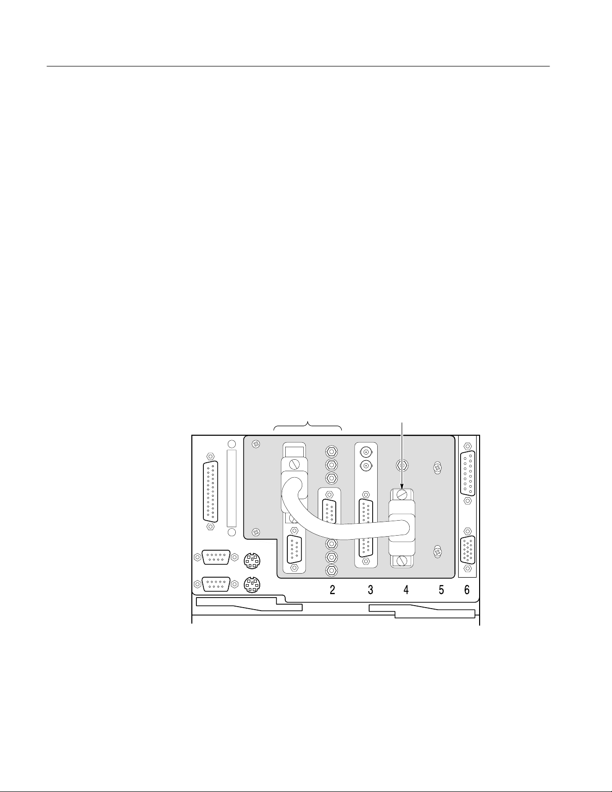
6. Verify that the Software Key is installed on the rear panel Parallel port. See
Figure 4 for port location. MTS 200 Series software applications will not run
without the Software Key installed; do not remove or misplace the Software
Key.
To use the Parallel port with the Software Key installed, attach any parallel
port cables directly to the Software Key. The Software Key does not interfere
with parallel communications.
NOTE. To run MTS 200 Series applications, you must install the Software Key on
the computer Parallel port. If you return the test system to a Tektronix Service
Center for upgrade or repair, include the Software Key.
Figure 3: Software Key
7. If you intend to connect the test system to a network, do so now. The
Proliant 1600 system computer has both AUI and RJ45 ethernet ports.
Neither ethernet port requires termination.
8. Connect the computer and monitor to a power source. Refer to Supplying
Power on page 7.
NOTE. Although the MTS 200 Series MPEG Test System is based on a standard
computer platform, do not install unauthorized expansion cards or use the test
system for purposes other than those recommended by Tektronix. Doing so can
cause your system to operate in an unexpected manner.
6
MTS 200 Series MPEG Test Systems Hardware Installation and Specifications

Parallel port
(Software Key
installed here)
Mouse port
Serial ports
Keyboard port
Getting Started
RTA I/OData Store I/O
VGA
graphics
card
Video
port
Supplying Power
SCSI
connector
RJ45 Ethernet
port
AUI Ethernet
port
Compaq video port
(Do not use)
Figure 4: Computer rear view showing input and output connectors. Option SS is
not installed.
The MTS 200 Series system computer and monitor are designed to operate from
a single-phase power source having one of its current carrying conductors at or
near earth ground (the neutral conductor). Power sources that have both current
carrying conductors live with respect to ground, such as phase-to-phase or
multiphase systems, are not recommended. A protective ground connection, by
way of the grounding conductor in the power cord, is essential for safe operation.
WARNING. The test system is designed for connection to an earth-grounded AC
outlet. To avoid risk of electrical shock or equipment damage, do not disable the
grounding plug.
Mains V oltage Range. You can power the test system computer and monitor from
mains that supply between 100 VAC and 230 VAC without setting a voltage
selection switch.
MTS 200 Series MPEG Test Systems Hardware Installation and Specifications
7

Getting Started
Mains Frequency . The test system computer and monitor operate on either 50 Hz
or 60 Hz line frequencies.
CAUTION. To prevent damage, protect the system computer from power fluctuations and temporary interruptions with a regulating noninterruptible power
supply. This device protects the hardware from damage caused by power surges
and voltage spikes. In addition, it allows the system to operate temporarily
during a power failure.
Power Cord Options. Unless a specific power cord option is ordered, the system
computer and monitor come standard with a power cord for North American
60 Hz, 115 VAC supplies. Table 2 lists the power cord options.
T able 2: Power cord identification
Plug configuration Normal usage Option number
North America
125 V/15A Plug
NEMA 5-15P
Europe
230 V
United Kingdom
230 V
Australia
230 V
Switzerland
230 V
Standard
A1
A2
A3
A5
8
MTS 200 Series MPEG Test Systems Hardware Installation and Specifications

Connecting the Data Store System Input and Outputs
The Data Store system is an integral part of the MTS 210 and MTS215 test
systems, enabling transport stream capture and output up to 60 Mbits/s.
Figure 5 shows the Data Store System input and output (I/O) connectors on the
computer rear panel. A detailed description of each connector follows the
illustration. For I/O port specifications, refer to the Specifications section
beginning on page 37.
Use the I/O ports that best suit your operating environment and signal sources.
To receive ASI input, use the optional D6002 DVB-PI adaptor. Contact your
Tektronix representative for ordering information.
Getting Started
ECL parallel/serial
I/O port
ECL control port
TTL 50 W serial
port (Clk I/O)
TTL 50 W serial
port (Data I/O)
External clock
input (Clk In)
10 Mbit serial
port (RS-422
levels I/O port)
G.703 input
G.703 output
(34.368 Mbits/s)
G.703 output
(8.448 Mbits/s)
Figure 5: Data Store inputs and outputs, computer rear. Option SS is not installed.
ECL Parallel/Serial I/O Port
The ECL Parallel/Serial I/O port receives and transmits MPEG-2 transport
streams at ECL levels. The port is differential, bidirectional, and operates
independently or in conjunction with the ECL Control port. The port transmits or
receives either parallel or serial data depending on the Data Store Administrator
application settings.
MTS 200 Series MPEG Test Systems Hardware Installation and Specifications
9

Getting Started
ECL Operating Modes. If the ECL Parallel/Serial I/O port is used independently
of the ECL Control port, there are three basic operating modes:
H Slave acquisition mode. Captures input signals using the ECL Parallel/Serial
I/O port clock signal as the timing source.
H Master generation mode. Outputs signals using the test system internal clock
as the timing source.
H Master generation with external clock mode. Outputs signals using the
external clock input (Clk In) as the timing source.
Using the ECL Parallel/Serial I/O port in conjunction with the ECL Control port
provides the following additional operating modes:
H Master acquisition mode. Captures input signals using control signals from
the ECL Control port to drive the signal source.
H Master acquisition with external clock mode. Same as above, but uses a
timing signal from the external clock input (Clk In) as the timing source.
ECL Control Port
G.703 Output
(8.448 and 34.368 Mbit/s)
and G.703 Input
H Slave generation mode. Outputs signals using the ECL Control port inputs as
the timing source.
NOTE. A“Master” generates the data transmission clock. A “Slave” returns an
external clock as the source.
Pinouts. For pinouts of the ECL Parallel/Serial I/O port, see Tables 8 and 9
beginning on page 43.
Using the ECL Control port is optional. This bidirectional differential control
port adds flexibility to the ECL Parallel and Serial Ports, providing three control
signals and two more operating modes. For a pinout of the ECL Control port, see
Table 10 on page 45.
The G.703 serial interface complies with the electrical characteristics of ITU-T
Recommendation G.703 (HDB3 code) for 8.448 Mbit/s and 34.368 Mbit/s.
The G.703 port operates in the following modes:
10
H Acquisition mode. Locks to the incoming signal and is self clocking.
H Generation (internal clock source) MODE. Uses an internal clock source.
The G.703 serial interface uses three Data Store circuit-board mounted SMB
connectors. One connector is a dedicated input for both bit rates. The other two
MTS 200 Series MPEG Test Systems Hardware Installation and Specifications

Getting Started
connectors are dedicated outputs, one for the 34.368 Mbit/s output and the other
for the 8.443 Mbit/s output. To reduce spurious emissions, connect only the
output being used.
10 Mbit Serial Port
(RS-422 Levels I/O Port)
Clock Input
The 10 Mbit Serial port transmits and receives MPEG transport signals and
includes bidirectional clocks and data pairs. The maximum operating frequency
is 10 Mbit/sec. The port uses RS-422 voltage levels with a line-to-line input
termination of 110 W. For a pinout of the 10MBit Serial port, see Table 14 on
page 47.
The 10 Mbit Serial port uses the following signals:
H Data In and Data Out (MPEG serial bit streams).
H Clock In and Clock Out (continuous data transmission).
The 10 Mbit Serial port operates in the following modes:
H Acquisition mode. Captures an input signal using an external timing
reference.
H Internal generation mode. Generates an output signal using the MTS 200
Series MPEG Test System internal clock as the timing reference.
H External generation mode. Generates an output signal using the Clock input
as the timing reference.
The Clk In connector provides an optional timing input for the ECL Serial, ECL
Parallel, TTL, and 10 Mbit Serial outputs. The input operates at a maximum
frequency of 45 MHz.
TTL 50 W Serial Port
(Data & Clock I/O)
MTS 200 Series MPEG Test Systems Hardware Installation and Specifications
The TTL 50 W Serial Port consists of dedicated clock and data inputs that
transmit and receive at TTL levels. The Data signal is a serial bitstream that uses
a continuous data transmission clock. The maximum operating frequency is
45 Mbits/s.
The
TTL 50 W Serial Port operates in the following modes:
H Acquire mode. Captures an input signal.
H Internal Generation mode. Generates a signal locked to the internal clock.
H External Generation mode. Generates a signal locked to an external reference
supplied by the Clock Input.
11

Getting Started
Data Store I/O Cables and
Mating Connectors
The MTS 200 Series MPEG Test System includes adapters to connect the Data
Store SMB connectors to standard BNC connectors. You may also need to
acquire or assemble other signal-connecting cables and adapters to install the test
system in your facility.
Cable Lengths. Maximum cable length is a function of data rate, cable type, and
ambient environment as summarized in Table 3. In general, low data rates
tolerate long cable lengths better than high data rates. Low loss coaxial cable and
low capacitance properly pair-twisted cable support longer transmission paths
than do miniature coaxial cable or ribbon cable. Induced RF noise can further
limit usable cable length.
The only test system ports designed for data transmission are the G.703 I/O
ports. All others ports are intended for short-range interconnects. With most
ports, you must control cable delay matching to maintain clock-to-data timing
margins or data integrity will suffer.
T able 3: Estimated maximum cable lengths
Port Rate (Mbits/s) Maximum length Cable type Comments
G.703 8.448 275 m Belden 8281 4 dB atten at
4.224 MHz
G.703 34.368 125 m Belden 8281 4 dB atten at
17.18 MHz
10 Mbit
(RS422)
10 Mbit
(RS422)
TTL 10 50 m RG58 type Calculated Value
TTL 50 25 m RG58 type Calculated Value
ECL Parallel 1 50 m Belden 81 12 Calculated Value
ECL Serial 45 5 m Belden 8112 Calculated Value
1 100 m 24 AWG
unshielded
twisted pair
10 15 m 24 AWG
unshielded
twisted pair
Ref. ANSI/TIA/
EIA-422-B-1994
Ref. ANSI/TIA/
EIA-422-B-1994
Adapters. The MTS 200 Series MPEG Test System includes six SMB-to-BNC
adapter cables. Three of the adapter cables match the impedance of the G.703
12
MTS 200 Series MPEG Test Systems Hardware Installation and Specifications

75 W inputs and outputs. The other three match the impedance of the TTL 50 W
Serial Port (CLK I/O, DATA I/O, and CLK IN).
NOTE. Do not leave SMB-to-BNC adapter cables on unused G.703 outputs.
Doing so can cause the test system to exceed EMC emission requirements.
Connecting the Real-Time Analyzer (RTA) Input and Outputs
MTS 205 and MTS215 test systems include the Real-Time Analyzer. Figure 6
shows the Real-Time Analyzer input and output (I/O) connectors on the
computer rear panel. A detailed description of each connector follows the
illustration. For I/O port specifications, refer to the Specifications section
beginning on page 49.
ASI outputASI input
Getting Started
Input
Trigger input
LVDS/ECL/RS422
Level input
LVDS/Mod ECL
output
Figure 6: Real-Time Analyzer inputs and outputs, computer rear. Option SS is not
installed.
You must provide input to the Real-Time Analyzer to monitor an MPEG-2,
DVB, or ATSC bitsream. The RTA accepts LVDS or ECL parallel input or ASI
serial input. In the standard configuration, either LVDS or ECL parallel input is
accepted as the default. If you provide serial input, you must change the software
configuration before monitoring an input data stream. To change the software
MTS 200 Series MPEG Test Systems Hardware Installation and Specifications
13

Getting Started
configuration, refer to Monitoring an Input Stream tutorial in the MTS200 Series
Real-Time Analyzer User Manual.
Output to the
Data Store System
(MTS215 only)
To capture and save portions of the input bitstream on the Data Store disks,
connect the parallel RTA output to the parallel Data Store input as shown in
Figure 7. Use the 25-conductor straight-through shielded cable provided with the
test system. From the Settings/Hardware Configuration menu, select Modified
ECL. For further details, refer to Capturing Input Streams (MTS 215 only)
tutorial in the MTS 200 Series Real-Time Analyzer User Manual.
RTA I/OData Store I/O
14
Output to Other
Equipment
Install RTA-to-Data
Store board cable
Figure 7: RTA output to Data Store input connection, computer rear
The Real-Time Analyzer can output all or part of the input stream through the
parallel and serial (ASI) connectors.
Parallel Output. Real-Time Analyzer parallel output is active only when the RTA
is running and analysis is occurring. The output level can be either LVDS or
modified ECL; refer to Table 18 on page 50 for parallel output characteristics.
Parallel output can be filtered by the Real-Time Analyzer software. For complete
information, refer to the MTS 200 Series Real-Time Analyzer User Manual.
MTS 200 Series MPEG Test Systems Hardware Installation and Specifications

Getting Started
Serial (ASI) Output. With data input through the ASI connector, the serial output
is continuously active. With a parallel input, the serial output is disabled when
data storage through the parallel output occurs.
The Serial output stream is always equivalent to the input stream and is not
affected by selections made on the Filtering Configuration tab of the Real-Time
Analyzer Settings window. Refer to Table 20 on page 50 for serial output
characteristics.
Trigger Input
The trigger input accepts a TTL level (0 to +5 V) signal you can use to control
capture of the Real-Time Analyzer input stream to the Data Store system
(MTS 215 only). You can configure the system to start/stop data capture on
either the rising edge (low to high transition) or the falling edge (high to low
transition) of the trigger signal. Refer to the MTS 200 Series Real-Time Analyzer
User Manual for further information.
Connecting the Synchronous Serial Interface Input and Outputs
The Option SS synchronous serial interface (SSI) converts MPEG-2 SMPTE
310M compliant synchronous serial transport streams at 19.39 and 38.78 Mbits/s
to synchronous parallel ECL output compatible with the the MTS 200 Series
Data Store and Real-Time Analyzer hardware. The interface also converts
DVB-compatible serial data streams to parallel output. The SSI data conversion
operates in both receiver and generator modes from 10 to 50 Mbits/s.
Figure 8 shows the SSI input and output connectors on the computer rear panel.
A detailed description of each connector follows the illustration.
SSI Input
Figure 8: SSI inputs and outputs, computer rear
MTS 200 Series MPEG Test Systems Hardware Installation and Specifications
SSI Output
ECL Parallel I/O
15

Getting Started
SSI Input
SSI Output
Parallel I/O
The SSI interface converts synchronous serial data from this input to synchronous parallel ECL output for the Data Store System or Real-Time Analyzer.
When an SSI signal is present at the SSI IN BNC connector, synchronous
parallel data is output through the ECL PARALLEL I/O connector and available
for input to Data Store System or Real-Time Analyzer ECL parallel inputs.
The SSI interface outputs synchronous serial data through the SSI OUT BNC
connector when a synchronous serial signal is present at the SSI IN BNC
connector. The SSI output bit rate is identical to the input bit rate. You must
terminate this output into 75 ohms.
Synchronous parallel signals input to the Parallel I/O connector (from the Data
Store System or Real-Time Analyzer ECL parallel outputs) are converted to
synchronous serial data if there is no signal present at the SSI IN BNC connector. The output is available at the SSI OUT connector. The SSI output bit rate is
identical to the parallel input bit rate. Synchronous parallel interface (SPI) output
is ECL-level compatible.
NOTE. Use the SSI Parallel I/O connector as an ECL bidirectional interface to
the Data Store System or Real-Time Analyzer.
Configuring the SSI
Circuit Board
A jumper on the SSI circuit board configures the SSI output for SMPTE 310M
(800 mV
is included.
For details on how to configure and adjust the SSI output, see the Tektronix
MPEG Test System Compaq Proliant Platform Service Manual, 071-0152-XX.
For I/O port specifications, refer to the Specifications section beginning on
page 52.
) or DVB (1 V
p-p
) compatible levels; a "10% calibration adjustment
p-p
16
MTS 200 Series MPEG Test Systems Hardware Installation and Specifications

First Time Operation
Getting Started
To power on the test system computer following installation, slide the power
switch cover plate to the right and press the power switch.
Slide power switch
cover plate
Power switch
Figure 9: Computer power switch
The Windows NT initialization process takes up to two minutes. Under normal
circumstances, no action is required until the Begin Logon message appears.
When the Begin Logon message appears, simultaneously press the
CTRL + ALT + DELETE keys to open the Logon Information dialog box. For further
information on the Windows NT initialization process, see the Windows NT
documentation included with the test system.
Logging On
To log on to the test system, enter MTS100 in the User name box, leave the
Password box blank, and press
ENTER (these are the default values set at the
factory). Use this logon for most of your work.
There are two other logons and passwords available. The first is guest with no
password. This level has only limited access to files and applications. The
second level is administrator with MPEG2 as the password. This user has
administrator privileges. You must use this logon when performing all software
upgrades.
MTS 200 Series MPEG Test Systems Hardware Installation and Specifications
17

Getting Started
CAUTION. The administrator user logon includes all privileges. If you are
connected to a network, you may have special privileges within the network. Do
not use this logon to perform normal operations.
Changing the Passwords. You can change passwords at this time. See the
Windows NT documentation for instructions. If you change any password, be
sure to create a new emergency repair disk as explained in the Software Repair
appendix of the MTS 200 Series Real-Time Analyzer User Manual.
Starting MTS200 Series
Applications
When logon is complete, the Tektronix MPEG Test System program group
window appears as shown below. Double-click the appropriate application icon
to begin your analysis.
NOTE. The above example shows the MTS 215 program group. The MTS205 and
MTS 210 test system program groups do not contain all application icons.
Exiting MTS200 Series
Applications
18
To exit an MTS 200 Series application, select Exit/Quit from the File menu or
click the close button in the upper-right corner of the application window.
Close
button
The current configuration is preserved and used the next time you run the
application.
MTS 200 Series MPEG Test Systems Hardware Installation and Specifications

Getting Started
Shutting Down the
Computer
To avoid loss of data and possible problems during subsequent Windows NT
initialization, always shut down Windows NT before switching the computer
power off. To shut down Windows NT, select Shut Down from the Start menu.
In the Shut Down Windows dialog box, select Shut down the computer? and
then click Yes. After a few seconds, the Shutdown Computer window appears
with the message It is now safe to turn off your computer. You can now power
off the computer.
CAUTION. Do not switch computer power off before the message It is now safe to
turn off your computer appears. Doing so can result in lost data and difficulty in
restarting Windows NT.
MTS 200 Series MPEG Test Systems Hardware Installation and Specifications
19

Getting Started
20
MTS 200 Series MPEG Test Systems Hardware Installation and Specifications

Functional Check
Data Store System
Use the procedures in this section to check the basic operation of the MTS 200
Series Data Store System and Real-Time Analyzer. These procedures check
instrument functionality only; specifications are not verified. To verify system
performance to warranted specifications, refer to the Performance Verification
section of the Tektronix MPEG Test System Compaq Proliant Platform Service
Manual, Tektronix part number 071-0152-XX.
Use the following procedure to verify the Data Store System basic function.
Procedures to verify Real-Time Analyzer basic function begin on page 28.
Test Equipment
Table 4 lists the test equipment you need to perform the Data Store System
functional check.
T able 4: Test equipment
Description
Oscilloscope Capable of measuring 6 V amplitude
Adapter cable, 50 W
Adapter cable, 75 W
Terminator, 50 W
Terminator, 75 W
Minimum requirements
and 1.4 ns rise time
SMB-to-BNC Tektronix part number
SMB-to-BNC Tektronix part number
BNC feedthrough Tektronix part number
BNC feedthrough Tektronix part number
Example
174-3578-XX
174-3579-XX
01 1–0049-XX
01 1–0103-XX
MTS 200 Series MPEG Test Systems Hardware Installation and Specifications
21

Functional Check
Procedure
1. Connect the test equipment as shown in Figure 10.
2. Power up and log on to the test system. Follow the instructions on page 17.
Computer
rear panel
G.703 output
(8.448 Mbits/s)
Test oscilloscope
Ch 1 input
75 W SMB-to-BNC
adapter cable
75 W feedthrough
terminator
Figure 10: Initial connections for the Data Store functional check
3. Once you have correctly logged on, double-click the Tektronix MPEG Test
System program group icon in the main window.
4. Double-click the Data Store Administrator icon in the Tektronix MPEG
Test System program window to start the application.
22
MTS 200 Series MPEG Test Systems Hardware Installation and Specifications

Functional Check
5. Set up the Data Store Administrator as follows:
a. Click the G (Generate) toolbar button.
b. In the resulting GENERATION dialog box, select any valid Data Store
file as the Source.
c. Select the Loop option.
d. In the Interface section of the dialog box, make the following selections:
H Protocol = Master
H Port = G703
H Output clock = 8.448 Mbits
e. Click Start.
6. Trigger the oscilloscope.
7. Verify a waveform frequency of approximately 4.224 MHz, an amplitude of
approximately 5 volts, and a rise time of approximately 4 ns. See Figure 11
for the location of the measurement points in the waveform.
8. Move the output cable to the G.703 34.368 M output as shown in Figure 11.
Computer rear panel
G.703 output
(34.368 Mbits/s)
T
R
10-90%
Ch 1 input
75 W SMB-to-BNC
adapter cable
Amplitude
Frequency
Test oscilloscope
75 W feedthrough
terminator
Figure 11: Setup for measuring the G.703 34.368 Mbit/s output
MTS 200 Series MPEG Test Systems Hardware Installation and Specifications
23

Functional Check
9. Set up the Data Store Administrator as follows:
a. Click the Stop (red hand) toolbar button.
b. Click the G (Generate) toolbar button.
c. In the resulting GENERATION dialog box, select any valid Data Store
file as the Source.
d. Select the Loop option.
e. In the Interface section of the dialog box, make the following selections:
H Protocol = Master
H Port = G703
H Output clock = 34.368 Mbits
f. Click Start.
10. Trigger the oscilloscope.
11. Verify a waveform frequency of approximately 17.2 MHz, a peak-to-peak
amplitude of approximately 2.3 volts, and a rise time of approximately 4 ns.
See Figure 11.
12. Remove the 75 W SMB-to-BNC adapter cable from the oscilloscope and the
test system G703 34.368 M Out connector.
13. Connect a 50 W SMB-to-BNC adapter cable from the TTL 50 W Clock I/O
Port, through a 50 W feedthrough terminator, to the oscilloscope input. See
Figure 12.
24
MTS 200 Series MPEG Test Systems Hardware Installation and Specifications

Functional Check
Computer rear panel
Clock I/O TTL
50 W serial port
T
R
10-90%
Ch 1 input
50 W SMB-to-BNC
adapter cable
Frequency
Test oscilloscope
Figure 12: Setup for measuring the TTL 50 ohm clock I/O port
Amplitude
50 W feedthrough
terminator
14. Set up the test system as follows:
a. Click the Stop (red hand) toolbar button.
b. Click the G (Generate) toolbar button.
c. In the resulting GENERATION dialog box, select any valid Data Store
file as the Source.
d. Select the Loop option.
e. In the Interface section of the dialog box, make the following selections:
H Protocol = Master
H Port = TTL
H Output clock = PLL
H Frequency = 1,000,000 Bits/s
f. Click Start.
MTS 200 Series MPEG Test Systems Hardware Installation and Specifications
25

Functional Check
15. Trigger the oscilloscope.
16. Verify a waveform frequency of approximately 1 MHz, an amplitude of
approximately 3.0 volts, and a rise time of approximately 2.0 ns. See
Figure 12.
17. Move the test system output cable to the TTL 50 W Data I/O Port. See
Figure 13.
Computer rear panel
Data I/O TTL
50 W serial port
T
R
10-90%
Ch 1 input
50 W SMB-to-BNC
adapter cable
Data rate
Test oscilloscope
Figure 13: Setup for measuring the TTL 50 ohm data I/O port
Amplitude
50 W feedthrough
terminator
26
18. Set up the test system as follows:
a. Click Start.
b. Click the Stop (red hand) toolbar button.
c. Click the G (Generate) toolbar button.
d. In the resulting GENERATION dialog box, select any valid Data Store
file as the Source.
e. Select the Loop option.
MTS 200 Series MPEG Test Systems Hardware Installation and Specifications

Functional Check
f. In the Interface section of the dialog box, make the following
selections:
H Protocol = Master
H Port = TTL
H Output clock = PLL
H Frequency = 45,000,000 Bits/s
g. Click Start.
19. Trigger the oscilloscope on the plus slope.
20. Verify a waveform amplitude of approximately 3.0 volts, a data rate of
45 MHz, and a rise time of approximately 2.0 ns. See Figure 13.
21. Move the test system output cable to the TTL 50 W Clock I/O Port as shown
in Figure 12.
22. Trigger the oscilloscope.
23. Verify a waveform amplitude of approximately 3.0 volts, frequency of
45 MHz, and rise time of approximately 2.0 ns. See Figure 12.
24. In the Data Store Administrator, click the Stop (red hand) toolbar button.
This completes the Data Store System functional check.
MTS 200 Series MPEG Test Systems Hardware Installation and Specifications
27
Functional Check
Real-Time Analyzer
Use the following procedure to verify the Real-Time Analyzer basic function. To
perform this procedure on an MTS 205, you need an additional test system such
as an MTS 210, MTS215, or another MPEG-2 signal source.
Overview and Preparation
To check the function of the Real-Time Analyzer, use the Multiplexer application
to create a transport stream file, output that file with the Data Store Administrator, and confirm that the Real-Time Analyzer shows a correct Program Allocation view of the stream.
To check a MTS 215 test system, connect the parallel Data Store output to the
parallel RTA input as shown in Figure 14. Use the 25-conductor straight-through
shielded cable provided with the test system (Tektronix part number
174-3799-XX). This connection allows you to generate and receive a test stream
with a single instrument.
To check an MTS 205 test system you need an external test stream source, such
as a Tektronix MPEG Test System MTS100, MTS 210, or MTS215, that can
multiplex and generate the appropriate output stream. Connect the source
machine Data Store output to the RTA input of the MTS 205 test system; then
use the source machine to create and output the test stream.
RTA InputData Store I/O
28
Figure 14: Connecting the MTS215 parallel Data Store output to the parallel
RT A input
MTS 200 Series MPEG Test Systems Hardware Installation and Specifications

Functional Check
Create a Transport Stream
Create a transport stream and save it on the Data Store disks with the following
procedure.
1. Power up and logon to the test system. See the instructions on page 17.
2. Once you have correctly logged on, double-click the Tektronix MPEG Test
System program group icon in the main window.
3. Double-click the Multiplexer icon in the Tektronix MPEG Test System
program group to start the application.
4. Choose New from the Multiplexer File menu to open the New configuration
file window.
5. Enter test in the File Name text box (the *.cfg extension is added
automatically) and click OK. The Multiplexer application displays the
default configuration hierarchy.
MTS 200 Series MPEG Test Systems Hardware Installation and Specifications
29

Functional Check
6. Click the Add (+) toolbar button to add a second program (PROG) icon to
the hierarchy.
7. Double-click the MUX (multiplex) icon and select Oscillator 34.368 MHz
in the resulting Multiplex Parameters window.
30
8. Click OK to close the Multiplex Parameters window.
9. Select (highlight) the Program1 icon and then click the Add (+) toolbar
button.
MTS 200 Series MPEG Test Systems Hardware Installation and Specifications

Functional Check
10. Click OK in the resulting Stream to add window to add a video stream icon
to the program hierarchy.
11. Click the Add button again and select Audio in the Stream to add window;
then click OK to add an audio stream icon to the first program hierarchy.
12. Double-click the program 1 VIDEO icon. A Video Stream window opens.
13. Click the Browse button and then enter 525\mobl_060.mp2 in the File
name box of the resulting Video Stream Selection window.
14. Click OK to select the file and close the selection window. Click OK again
to close the Video Stream window.
15. Double-click the program 1 AUDIO icon. An Audio Stream window opens.
16. Click the Browse button and select the file 15KZ_192.MP2 from the
resulting Audio Stream Selection window.
17. Click OK to first close the Audio Stream Selection window and then the
Audio Stream window. The program 1 hierarchy should now show the
selected video and audio files.
MTS 200 Series MPEG Test Systems Hardware Installation and Specifications
31

Functional Check
18. Use the preceding procedure (steps 9 through 17) to add a video stream and
audio stream to program 2. Attach the video stream 625\mobl_060.mp2 to
the VIDEO icon and attach the audio stream 15KZ_256.mp2 to the AUDIO
icon.
19. Select Go from the Multiplex menu and enter c:\test.trp in the File
name box of the resulting Multiplex Output File window. Click OK to begin
multiplexing the test.trp file.
20. When the process is complete, click OK in the resulting Information dialog
box and then exit the Multiplexer application (select Exit from the File
menu).
Output the Stream
Configure the Data Store system and output test.trp with the following
procedure.
1. Double-click the Data Store Administrator icon in the Tektronix MPEG
Test System program group to start the Data Store Administrator application.
2. Click the W command button to open the File Write to CARB dialog box.
3. Browse to and select c:\test.trp to write to the Data Store disks. By default,
the <CARB file name> is test.trp.
4. Click Start to copy the file from the system disk to the Data Store disks;
then click OK when prompted to acknowledge transfer completion.
32
5. Select (highlight) test.trp, which is the last file listed in the SINGLE SHOT
PARTITION portion of the File information list.
MTS 200 Series MPEG Test Systems Hardware Installation and Specifications

Functional Check
6. Click the G toolbar button to open the GENERATION window.
7. Make the following selections and settings as necessary:
H Loop selected
H Board file = test.trp
H Protocol = Master
H Port = // ECL
H Output clock = PLL
H Frequency = 34,368,000 Bits/s
H Control signals selected
H Nr useful bytes = 188
H Stuffing byte (hexa) = FF
H Synchro. signal size (bytes) = 1
8. Click Start to begin generating test.trp.
9. Minimize the Data Store Administrator application.
MTS 200 Series MPEG Test Systems Hardware Installation and Specifications
33

Functional Check
Analyze the Stream
Start the Real-Time Analyzer application and confirm it correctly identifies the
contents of test.trp.
1. Double-click the Real-Time Analyzer icon in the Tektronix MPEG Test
System program group to start the RTA.
2. Select Restore standard from the RTA Configuration menu; then click OK
in the resulting dialog box to confirm your choice.
3. Click the Start (green traffic light) toolbar button to begin analysis.
4. Press F10. After a second or two, the application window should resemble the
following screen capture.
34
MTS 200 Series MPEG Test Systems Hardware Installation and Specifications

Functional Check
5. Confirm that the Program Allocation pie chart correctly shows two program
slices. (The PSI slice is too small to display.)
6. Confirm that additional error messages appear when the end of the file is
reached, approximately once every 15 seconds.
7. Confirm, after the Data Store system completes at least one loop, that the
program 1 transport rate settles at approximately 6.78 Mbits/s, or almost
20% of the transmission rate.
If the analyzer successfully checks test.trp, proper function of the Real-Time
Analyzer is confirmed. If the program allocation display does not show the pie
chart or report transmission rates correctly, switch the test system off and verify
that the RTA board is firmly seated in the EISA bus connector (slot 4 of the
computer card cage).
After a successful functional check, exit the Real-Time Analyzer and the Data
Store Administrator, delete test.trp from the c:\ (root) directory, and shut down
the computer.
MTS 200 Series MPEG Test Systems Hardware Installation and Specifications
35

Functional Check
36
MTS 200 Series MPEG Test Systems Hardware Installation and Specifications

Specifications
Á
Á
Á
Á
Á
Á
Á
Á
Á
Á
Á
Á
Á
Á
Á
Á
Á
This section lists the electrical, environmental, and physical specifications of the
MTS 200 Series MPEG Test System. All specifications are guaranteed unless
labeled typical. Typical specifications are provided for your convenience and are
not guaranteed. Electrical characteristics apply to test systems operating within
the environmental conditions specified in Table 27 on page 55.
To verify performance of the Data Store system, use the procedures in the
performance verification section of the MPEG Test System Service Manual, an
optional accessory. Contact your Tekronix representative for ordering information.
Data Store System Electrical Characteristics
Tables 5 through 15 list the electrical characteristics of the Data Store I/O and
control ports.
T able 5: G.703 — 8.448 MHz
Characteristic Description Supplemental information
Standards conformance
Connector
Line encoding
Serial bit rate
Generation/acquisition test
ББББББББББ
Input voltage levels
ББББББББББ
Standard
ÁÁББББББББ
Return loss (75 W)
ÁÁББББББББ
Connector
Jitter tolerance
Á
Á
ББББББББ
ББББББББ
8.448 Mbits/s ±10 ppm
Error free
ББББББББББ
ББББББББББÁББББББББББ
ББББББББББÁББББББББББ
ББББББББББÁББББББББББ
ББББББББББ
ББББББББББ
ITU-CCITT G.703, G.823
SMB
HDB3
Tested with a 10 Mbyte file (within the
ББББББББББ
constraints of synchronization)
Standard level within 0 to 4 dB cable
attenuation at one-half clock
Mark from 2.033 V to 2.607 V
Space from –0.237 to +0.237 V
21 1 kHz to 422 kHz: 12 dB
422 kHz to 8.448 MHz: 18 dB
8.448 to 12.672 MHz: 14 dB
Male SMB shared with 34.36 Mbit input
20 Hz to 400 Hz: 177 ns peak to peak
ББББББББББ
3 kHz to 400 kHz: 23.6 ns peak to peak
ББББББББББ
400 Hz to 3 kHz: log prorated
Output
Pulse width
Pulse “mark” amplitude
2.37 V ±0.237 V
59 ns nominal
MTS 200 Series MPEG Test Systems Hardware Installation and Specifications
37

Specifications
Á
Á
Á
Á
Á
Á
Á
Á
Á
Á
Á
Á
Á
Á
Á
Á
Á
Á
Á
T able 5: G.703 — 8.448 MHz (cont.)
Characteristic Supplemental informationDescription
No-pulse “space” voltage
Pulse shape
ББББББББ
Required receiver termination
Jitter
ББББББББ
ББББББББ
ББББББББ
ББББББББ
ББББББББ
Connector
Return loss
ББББББББ
0 ±0.237 V
ББББББББББÁББББББББББ
Conforms to 8.448 MHz Pulse Mask G.703,
as shown in Figure 15.
75 W nominal resistive
15 ns peak to peak with a 20 Hz lower cutoff
ББББББББББ
ББББББББББ
ББББББББББ
ББББББББББ
ББББББББББ
ББББББББББ
and a 400 kHz upper cut-off filter
ББББББББББ
5 ns peak to peak with a 3 kHz lower cutoff
ББББББББББ
and a 400 kHz upper cut-off filter
ББББББББББ
Allows a cascade of ten different regenera-
ББББББББББ
tors before system limit is reached
Male SMB
21 1 kHz to 422 kHz: 12 dB
ББББББББББÁББББББББББ
422 kHz to 8.448 MHz: 18 dB
8.448 to 12.672 MHz: 14 dB
38
MTS 200 Series MPEG Test Systems Hardware Installation and Specifications

2.370 V
1.185 V
Specifications
69 ns
Nominal
pulse
0.237 V 0.237 V
35 ns
0 V
0.237 V 0.237 V
0.474 V 0.474 V 0.474 V
49 ns
59 ns
100 ns
118 ns
Figure 15: Pulse specification for G.703 8.448 MHz pulse
MTS 200 Series MPEG Test Systems Hardware Installation and Specifications
39

Specifications
Á
Á
Á
Á
Á
Á
Á
Á
Á
Á
Á
Á
Á
Á
Á
Á
Á
Á
Á
Á
Á
Á
Á
Á
Á
Á
Á
Á
Á
Á
Á
Á
Á
Á
T able 6: G.703 — 34.368 MHz
Characteristic Description Supplemental information
Standards conformance
Connector
Line encoding
Generation/acquisition test
БББББББББ
Serial bit rate
Input voltage levels
БББББББББ
Standard
ББББББББ
Return loss (75 W)
ББББББББ
Connector
Jitter tolerance
ББББББББ
ББББББББ
Output
Pulse width
Pulse mark amplitude
No-pulse space voltage
Pulse shape
ББББББББ
Required receiver termination
Jitter
ББББББББ
ББББББББ
ББББББББ
ББББББББ
ББББББББ
Return loss
ББББББББ
ITU-CCITT G.703, G.823
SMB
HDB3
Error free
ББББББББББ
Tested with a 10 MB file (within the
ББББББББББ
constraints of synchronization)
34.368 Mbits/s ±20 ppm
Standard level within 0 to 4 dB cable
ББББББББББÁББББББББББ
attenuation at 1/2 clock
Mark from 0.9 V to 1.1 V
ББББББББББÁББББББББББ
Space from –0.1 V to +0.1 V
860 kHz to 1.72 MHz: 12 dB
ББББББББББÁББББББББББ
1.72 MHz to 34.368 MHz: 18 dB
34.368 to 51.55 MHz: 14 dB
Male SMB (shared with the 8 Mbit input)
ББББББББББ
ББББББББББ
100 Hz to 1 kHz: 43.7 ns peak to peak
ББББББББББ
10 kHz to 800 kHz: 4.37 ns peak to peak
ББББББББББ
1 kHz to 10 kHz: log prorated
14.5 ns nominal
1.0 V ±0.1 V
0 ±0.1 V
Conforms to 34.368 MHz Pulse Mask
ББББББББББÁББББББББББ
G.703, as shown in Figure 16.
75 W nominal resistive
10 ns peak to peak with a 100 Hz lower
ББББББББББ
ББББББББББ
ББББББББББ
ББББББББББ
ББББББББББ
ББББББББББ
cutoff and a 800 kHz upper cut-off filter
ББББББББББ
2.45 ns peak to peak with a 10 kHz lower
cutoff and a 800 kHz upper cut-off filter
ББББББББББ
ББББББББББ
Allows a cascade of ten different regenerators before system limit is reached
ББББББББББ
860 kHz to 1.72 MHz: 12 dB
ББББББББББÁББББББББББ
1.72 MHz to 34.368 MHz: 18 dB
34.368 MHz to 51.55 MHz: 14 dB
40
MTS 200 Series MPEG Test Systems Hardware Installation and Specifications

1.0 V
0.5 V
Specifications
17 ns
Nominal
pulse
0.1 V 0.1 V
8.65 ns
0 V
0.1 V 0.1 V
0.2 V 0.2 V 0.2 V
12.1 ns
14.55 ns
24.5 ns
29.1 ns
Figure 16: Pulse specification for G.703 34.368 MHz
MTS 200 Series MPEG Test Systems Hardware Installation and Specifications
41

Specifications
Á
Á
Á
Á
Á
Á
Á
Á
Á
Á
Á
Á
Á
Á
Á
Á
Á
Á
Á
Á
Á
Á
T able 7: ECL parallel and serial I/O and control ports
Characteristic Description Supplemental information
Connectors
БББББББББ
БББББББББ
Generation/acquisition test
БББББББББ
Master/slave
Slave/master (w/control)
БББББББББ
Digital format
ББББББББББ
ББББББББББ
ББББББББББ
ББББББББББ
Parallel Data: D-25, see pinout Table 8.
ББББББББББ
Serial Data: D-25, see pinout Table 9.
Flow Control: D-9, see pinout Table 10.
ББББББББББ
Tested with a 10 MB file at maximum data
rates (within the constraints of synchroniza-
ББББББББББ
tion)
ББББББББББ
Binary , positive logic
Input
Maximum data rate
ББББББББ
ББББББББББÁББББББББББ
Serial: 55 Mbits/s
Parallel: 7.5 Mbyte/s
Minimum data rate Clock Rate: 1 MHz
Serial: 1 Mbits/s
Parallel: 125 Kbyte/s
Signal level amplitude
ББББББББ
Time reference
ББББББББББÁББББББББББ
Differential ECL compliant with the ECL
100K levels
Rising edge of the clock
Output
Maximum data rate
ББББББББ
Minimum data rate
ББББББББ
ББББББББББÁББББББББББ
ББББББББББÁББББББББББ
Serial: 55 Mbits/s
Parallel: 7.5 Mbytes/s
Clock rate: 1 MHz
Serial: 1 Mbits/s
Parallel: 125 Kbyte/s
Clock-to-data timing Data changes within 5 ns of falling clock
edge
Signal level amplitude
ББББББББ
Required receiver termination
ББББББББББÁББББББББББ
Differential ECL compliant with the ECL
100K levels
110 W line to line
42
MTS 200 Series MPEG Test Systems Hardware Installation and Specifications

T able 8: ECL parallel data pinout
4
5
4
5
9
9
4
5
ECL parallel pinout Pin Function Pin Function
1 DCLK 14 DCLK
1
2
3
6
7
8
10
11
12
13
Asserted Low differential signal.
2 Ground 15 Ground
1
3 DA TA 7 16 DA TA 7
1
4 DA TA 6 17 DA TA 6
16
17
5 DA TA 5 18 DA TA 5
18
6 DA TA 4 19 DA TA 4
1
7 DA TA 3 20 DA TA 3
20
8 DA TA 2 21 DA TA 2
21
21
9 DA TA 1 22 DA TA 1
22
23
10 DATA 0 23 DATA 0
2
11 DVALID 24 DVALID
2
12 PSYNC 25 PSYNC
13 Shield
Specifications
MTS 200 Series MPEG Test Systems Hardware Installation and Specifications
43

Specifications
4
5
4
5
9
9
5
T able 9: ECL serial data pinout
ECL serial pinout Pin Function
1 DCLK
1
2
3
6
7
8
10
11
12
13
Asserted Low differential signal.
2 Ground
1
3 thru 9 Not managed
1
10 DATA 0
16
17
11 DVALID
18
12 PSYNC
1
13 Shield
20
14 DCLK
21
21
15 Ground
22
23
16 thru 22 Not managed
24
23 DATA 0
2
24 DVALID
25 PSYNC
Active edge
data_clock
Data
data_valid
Figure 17: ECL serial timing
D0
44
MTS 200 Series MPEG Test Systems Hardware Installation and Specifications

T able 10: ECL control data pinout
5
9
ECL control pinout Pin Function
1 CHCLK (channel clock)
2 Ground
1
2
2
3
4
Asserted Low differential signal.
3 CHSYNC (channel sync)
6
4 CHCLKEN (channel clock enable)
7
5 Shield
8
6 CHCLK (channel clock)
7 Ground
8 CHSYNC (channel sync)
9 CHCLKEN (channel clock enable)
Specifications
demand_clock
CHCLK
demand_clock_enable
CHCLKEN
Data and stream
data_valid
data_clock
DCLK
Figure 18: ECL control timing
Active edge
Stuffing bytes
MTS 200 Series MPEG Test Systems Hardware Installation and Specifications
45

Specifications
Á
Á
Á
Á
Á
Á
Á
Á
Á
Á
Á
Á
Á
Á
Á
T able 11: TTL 50 ohm data and clock I/O ports
Characteristic Description Supplemental information
Connectors
Rise & fall times
Output signal swing into 50 W
БББББББББ
Digital format
Maximum data rate
Low: t0.3 V
ББББББББББ
High: u2.65 V
Male SMB
Between 2 ns and 6.5 ns
ББББББББББ
Binary , positive logic
45 Mbits/s
Minimum data rate 1 Mbits/s
Generation/acquisition test
БББББББББ
БББББББББ
Input termination
Timing diagram
БББББББББ
Error free
ББББББББББ
ББББББББББ
Tested with a 10 MB file at maximum data
ББББББББББ
rates (within the constraints of the stop/start
ББББББББББ
bits)
50 W nominal resistive
DA TA signal is stable on the leading edge of
ББББББББББÁББББББББББ
the clock signal. See Figure 19.
Clock-to-data timing Data changes within 5 ns of falling clock
edge
Input signal level amplitude
БББББББББ
ББББББББББÁББББББББББ
TTL Low: t0.8 V
TTL High: u2.0 V
T able 12: TTL 50 ohm clock in port
Characteristic Description Supplemental information
Clock port voltage levels
БББББББББ
Termination
Range
ББББББББББÁББББББББББ
Clock
Data
TTL Low: t0.8 V
TTL High: u2.0 V
50 W, nominally resistive
125 kHz to 45 MHz
Figure 19: Timing for TTL50 ohm and separate clock input
46
MTS 200 Series MPEG Test Systems Hardware Installation and Specifications

T able 13: 10 Mbit serial I/O RS422 level port
Á
Á
Á
Á
Á
Á
Á
Á
5
9
Characteristic Description Supplemental information
Specifications
Connector
10 Mbit serial voltage levels
БББББББББББ
Input
ÁÁБББББББББ
Output
ÁÁБББББББББ
ББББББББББÁБББББББББ
ББББББББББÁБББББББББ
ББББББББББÁБББББББББ
9-pin subminiature D-type (see Table 14).
Differential outputs measured single
ended
Low: t0.5 V differential
High: u2.5 V differential
Low: t0.5 V
High: u2.5 V
Common mode range ±5 Volts
10 Mbit serial rise and fall times
Maximum data rate
Between 2 ns and 12 ns
10 Mbits/s
Minimum data rate 1 Mbits/s
Clock-to-data timing Data changes within 10 ns of falling clock
edge
Generation/acquisition test
БББББББББББ
ББББББББББÁБББББББББ
Tested with a 10 MB file at maximum
data rates (within the constraints of the
stop/start bits)
T able 14: 10 Mbit serial data pinout
10 Mbit serial pinout Pin Function
1 DA TA IN
2 CLK IN
1
2
2
3
4
3 DA TA OUT
6
4 CLK OUT
7
5 Ground
8
6 DA TA IN
7 CLK IN
8 DA TA OUT
9 CLK OUT
Asserted Low differential signal.
MTS 200 Series MPEG Test Systems Hardware Installation and Specifications
47

Specifications
Clock
Data
Figure 20: 10 Mbit serial timing
T able 15: Phase lock loop (general)
Characteristic Description Supplemental information
Range
Resolution
Jitter
Settling time
Frequency Accuracy
125 kHz to 60 MHz
1 Hz
0.2 UI peak to peak over a 1000 UI delay
3 seconds after frequency change
10 ppm ±resolution
48
MTS 200 Series MPEG Test Systems Hardware Installation and Specifications

Real-Time Analyzer Electrical Characteristics
Á
Á
Á
Á
Á
Á
Á
Á
Á
4
5
4
5
9
9
4
5
Tables 16 through 20 list the electrical characteristics of the Real-Time Analyzer
I/O ports.
T able 16: LVDS/ECL/RS422 level in port
Specifications
Characteristic
ББББББББ
Connector
Input data rate
ББББББББ
Signal amplitude, typical
Signal common mode range,
ББББББББ
typical
Description
БББББББББББ
D-25
Maximum: 60 Mbits/s
Minimum: 1 Mbits/s
БББББББББББ
Maximum: 2.0 V
Minimum: 100 mV
–1.8 V to +2.5 V
БББББББББББ
p-p
p-p
Supplemental information
БББББББББББ
See pinout Table 17
БББББББББББ
БББББББББББ
T ermination, nominal 100 ohms resistive Line to line
Timing reference Rising edge of clock
Clock-to-data timing Data must be stable to ±5 ns of the rising clock
edge
T able 17: LVDS/ECL/RS422 parallel data pinout
Parallel input pinout Pin Function Pin Function
1 DCLK 14 DCLK
1
2
3
6
7
8
10
11
12
13
Asserted Low differential signal.
2 Ground 15 Ground
1
3 DA TA 7 16 DA TA 7
1
4 DA TA 6 17 DA TA 6
16
17
5 DA TA 5 18 DA TA 5
18
6 DA TA 4 19 DA TA 4
1
7 DA TA 3 20 DA TA 3
20
8 DA TA 2 21 DA TA 2
21
21
9 DA TA 1 22 DA TA 1
22
23
10 DATA 0 23 DATA 0
2
11 DVALID 24 DVALID
2
12 PSYNC 25 PSYNC
13 Shield
MTS 200 Series MPEG Test Systems Hardware Installation and Specifications
49

Specifications
Á
Á
Á
Á
Á
Á
Á
Á
Á
Á
Á
Á
ББББББББББББ
ББББББББББББ
ББББББББББББ
Á
ББББББББББББ
Á
Á
ББББББББББББ
ББББББББББББ
ББББББББББББ
ББББББББББББ
Á
ББББББББББББ
Á
Á
ББББББББББББ
T able 18: LVDS/MOD ECL out port (parallel)
Characteristic
Connector
Signal amplitude
ББББББББ
LVDS
БББББББ
Modified ECL
БББББББ
БББББББ
Description
D25
Selectable by software to LVDS or modified
БББББББББББ
ECL levels
Maximum: 454 mV
БББББББББББ
Minimum: 247 mV
Maximum: 454 mV
Minimum: 247 mV
БББББББББББ
БББББББББББ
p-p
p-p
p-p
p-p
Supplemental information
See pinout Table 17
ББББББББББ
100 ohm line-to-line termination
ББББББББББ
100 ohm line-to-line termination
ББББББББББ
Modified Differential ECL is less than the
ББББББББББ
typical 100K ECL level of [700 mV
Common mode voltage
LVDS output, typical
Modified ECL output
0.85 V
–1.80 V maximum, –1.50 V minimum
T able 19: ASI in port
Characteristic
Connector
Input bit rate 270Mbits/s ±100ppm
Description
BNC
Supplemental information
p-p
.
Transport stream
Signal amplitude, typical
ББББББББ
60 Mbits/s max
Maximum: 800 mV
Minimum:: 200 mV
БББББББББББ
p-p
p-p
Content of bit rate
БББББББББББ
T ermination, nominal 75 ohms
Return loss, typical
Data formats
–17 dB minimum
Accepts both burst and packet modes
27 MHz to 270 MHz
T able 20: ASI out port
Characteristic
Connector
Output bit rate 270 Mbits/s ±100 ppm
Signal amplitude
ББББББББ
Rise and fall times, typical
Description
BNC
Maximum: 880 mV
БББББББББББ
Minimum: 500 mV
p-p
p-p
1.2 ns maximum
Supplemental information
Into 75 W load
БББББББББББ
20% to 80%
50
MTS 200 Series MPEG Test Systems Hardware Installation and Specifications

T able 21: PCR analysis accuracy
Á
Á
Specifications
Characteristic
Frequency Offset readout
Accuracy
Drift, typical
Jitter readout and graphical display accuracy, typical
ББББББББББББ
Parallel input
ASI input
Description
±3.0 ppm
±1 ppm per year
БББББББББ
±30 ns peak
±60 ns peak
MTS 200 Series MPEG Test Systems Hardware Installation and Specifications
51

Specifications
Á
ББББББББББББ
Á
Á
ББББББББББББ
ББББББББББББ
ББББББББББББ
Á
ББББББББББББ
Á
ББББББББББББ
Synchronous Serial Interface Electrical Characteristics
Tables 22 through 24 list the electrical characteristics of the Synchronous Serial
Interface I/O ports.
T able 22:
Characteristic
Connector
Bit rate
Data format
Signal amplitude
Signal DC offset
SSI input
ББББББББ
ББББББББ
Description
БББББББББББ
Supplemental information
БББББББББББ
BNC, male
10 Mbits/s to 50 Mbits/s
SMPTE 310M and DVB SSI compliant
Minimum: 250 mV
БББББББББББÁБББББББББББ
Maximum: 1100 mV
p-p
p-p
±0.5 VDC, maximum
T ermination, nominal 75 W
Return loss, typical 100 kHz to 77.6 MHz: –30 db, typical
100 kHz to 105 MHz: –15 db, minimum
Synchronization Occurs under the following conditions:
1.) The sync byte is 47 hex and the packet
length is 188 bytes.
2.) The sync byte is 47 hex and the packet
length is 204 bytes; the condition when
the 16 Reed Solomon (RS) bytes are
dummies.
3.) The packet length is 204 bytes and the
following sequence occurs: for 7 packets
the sync byte is 47 hex and for 1 packet
the sync byte is B8 hex. This condition
sometimes occurs when the 16 RS bytes
are valid. In such a case, the DVALID line
in the SPI output is high for the 16
RS bytes.
Packet length 188 or 204 bytes
52
MTS 200 Series MPEG Test Systems Hardware Installation and Specifications

Specifications
Á
Á
Á
Á
Á
Á
Á
Á
Á
Á
Á
Á
Á
Á
Á
Á
Á
T able 23:
SSI output
Characteristic Description Supplemental information
Connector
Data format
Output Bit rate
ББББББББ
ББББББББ
ББББББББ
ББББББББ
Transport clock drift rate
BNC, male
SMPTE 310M, settable:
БББББББББББ
19,392,658.5 ±54 bits/s for 8 VSB
38,785,316.9 ±108 bits/s for 16 VSB
БББББББББББ
БББББББББББ
DVB, adjustable:
10 Mbits/s to 50 Mbits/s
БББББББББББ
19,392,685.5 Hz: ±.54 Hz/s 〈±0.028 ppm/s)
SMPTE 310M and DVB SSI compliant
БББББББББББ
БББББББББББ
БББББББББББ
БББББББББББ
Measured below 1 Hz
38,758,316.9 Hz: ±1.10 Hz/s
Interface clock jitter
Signal
ББББББББ
Amplitude
SMPTE 310M jumper
DVB jumper
Peak to peak: 2 ns
БББББББББББÁБББББББББББ
Minimum: Maximum:
720 mV
900 mV
p-p
p-p
880 mV
1100 mV
p-p
p-p
Measured at 19,392,658 and 38,758,317 Hz
Set by convertor board jumper
DC offset, maximum ±0.5 VDC
Rise and fall time
1
Minimum: 0.4 ns
Measured between 20% and 80%
Maximum: 5.0 ns
Overshoot 10% of signal amplitude maximum
Output impedance, nominal
Return loss, typical
ББББББББ
75 W
Minimum: –30 db 100 kHz to 77.6 MHz
БББББББББББ
–15 db 77.6 MHz to 105 MHz
БББББББББББ
1
Rise and fall times shall not differ by more than 1.6 ns.
T able 24: Parallel I/O port
Characteristic Description Supplemental information
Connector
Input
Bit rate
Data format Synchronous parallel interface ECL logic levels
Signal amplitude
Clock-to-data timing Data read on rising clock edge. Data
T ermination, nominal
MTS 200 Series MPEG Test Systems Hardware Installation and Specifications
D-25, female
10 Mbits/s to 50 Mbits/s
Differential ECL
100 W line to line
See pinout Table 25
Compliant with ECL 100 K-Series levels.
changes within 10 ns of clock falling edge.
53

Specifications
Á
Á
Á
4
5
4
5
9
9
4
5
T able 24: Parallel I/O port (Cont.)
Characteristic Supplemental informationDescription
Output
Input bit rate
Data format
Signal amplitude, typical
ББББББББ
10 Mbits/s to 50 Mbits/s
Synchronous parallel interface
Logic high: –0.9 V
ББББББББББ
Logic low: –1.7 V
ECL logic levels
Differential ECL. Compliant with ECL 100 k
ББББББББББ
levels.
Clock-to-data timing Data valid (stable) on rising clock edge.
Data changes within 10 ns of clock falling
edge.
Receiver termination, nominal
100 W line to line
With –2 V pull down
T able 25: SSI parallel I/O data pinout
ECL parallel pinout Pin Function Pin Function
1 DCLK 14 DCLK
1
2
3
6
7
8
10
11
12
13
2 Ground 15 Ground
1
3 DA TA 7 16 DA TA 7
1
4 DA TA 6 17 DA TA 6
16
17
5 DA TA 5 18 DA TA 5
18
6 DA TA 4 19 DA TA 4
1
7 DA TA 3 20 DA TA 3
20
8 DA TA 2 21 DA TA 2
21
21
9 DA TA 1 22 DA TA 1
22
23
10 DATA 0 23 DATA 0
2
11 DVALID 24 DVALID
2
12 PSYNC 25 PSYNC
13 Shield
Asserted Low differential signal.
54
MTS 200 Series MPEG Test Systems Hardware Installation and Specifications

Test System Characteristics
Tables 26 through 29 list general characteristics of the MTS 200 Series MPEG
Test System.
T able 26: Power requirements
Characteristic Description Supplemental information
Line voltage 100 VAC to 240 VAC
Line frequency 50 Hz / 60 Hz
Rated input current 6 A to 3 A
Power consumption
1
Without monitor.
T able 27: Environmental characteristics
1
160 W nominal
Specifications
Characteristic Supplemental information
Temperature
Nonoperating –20° C (–4° F) to +60° C (140°F), maximum rate of change 20°C (36°F) per hour
Operating +10° C (50° F) to +35° C (95° F), maximum rate of change 10°C (18°F) per hour
Altitude
Nonoperating 0 to 30,000 ft (9144 m)
Maximum operating 0 to 6,562 ft (2000 m)
Humidity
Maximum operating 80% for temperatures up to +31°C (88° F), decreasing linearly to 66% at +35°C (95° F)
Nonoperating 5% to 90% humidity, noncondensing
T able 28: Physical characteristics
Characteristic Supplemental information
Dimensions
Net weight 65 lb (29.54 kg) without accessories
Shipping weight 104 lb (47.17 kg) with all accessories except monitor.
1
1
Height 17.92 inch (45.52 cm)
Width 8.83 inch (22.43 cm)
Depth 22.67 inch (57.58 cm)
Monitor is shipped separately.
Does not include monitor, keyboard, mouse, or feet.
MTS 200 Series MPEG Test Systems Hardware Installation and Specifications
55

Specifications
T able 29: Certifications and compliances
Category Standard
EC declaration of conformity Meets the intent of Directive 89/336/EEC for Electromagnetic Compatibility and Low Voltage
Directive 73/23/EEC for Product Safety.
Compliances demonstrated to the following specifications as listed in the Official Journal of the
European Communities:
EN 50081-1 Emissions:
EN 55011 Class A Radiated and Conducted Emissions
EN 50082-1 Immunity:
IEC 801-2 Electrostatic Discharge Immunity
IEC 801-3 Radiated RF Electromagnetic Field Immunity
IEC 801-4 Electrical Fast Transient/Burst Immunity
Conditional Statements:
1) Using high quality shielded cables, including those supplied as standard accessories.
Low Voltage directive 73/23/EEC, amended by 93/68/EEC:
EN 60950 Safety of Information Technology Equipment, Including
Electrical Business Equipment
Australia declaration of conformity Complies with electromagnetic compatibility standards as required under the
Radio CommunicationsAct.
Compliance to:
AS/NZS 2064.1/2 Industrial, Scientific, and Medical Equipment: 1992
(demonstrated with compliance to EN55011 class A)
Safety class Class I grounded product
56
MTS 200 Series MPEG Test Systems Hardware Installation and Specifications

Repackaging
The original MTS 200 Series MPEG Test System packaging materials provide
maximum protection during shipping. If you return the test system to Tektronix
for upgrade or repair, use the original packaging materials to avoid damage.
NOTE. Use the original shipping containers to return test system components to
Tektronix service centers. Tektronix cannot honor warranties for components
damaged during shipping. To minimize the risk of shipping damage, purchase
replacement packaging materials if necessary.
Obtaining Replacement Packaging
You can order replacement packaging materials from Tektronix; Table 30 on
page 59 lists the available items. Contact your nearest Tektronix office or
representative to obtain new packaging materials.
Repackaging the Test System
Figure 21 provides repackaging details for the test system computer. To prevent
damage to the packaging materials, remove the computer front door panel and
feet before packing. Do not repackage the computer keyboard, mouse, feet, or
front door panel when shipping the test system to a Tektronix Service Center. For
the test system to function properly during servicing, remember to return the
Software Key.
NOTE. Include the Software Key when returning the test system to a Tektronix
service center.
Removing the Computer
Front Door
1. Open the computer front door completely.
2. Lift up the door to disengage the right-side hinge pins from the hinge-pin
holes in the computer chassis. Refer to Figure 2 on page 5 for additional
details.
3. Remove the door.
MTS 200 Series MPEG Test Systems Hardware Installation and Specifications
57

Repackaging
Removing the Computer
Feet
Packing the Computer
1. Carefully turn the computer over onto its top.
2. Use a T-15 TORX tip screwdriver to remove each computer foot mounting
screw. Refer to Figure 1 on page 4 for additional details.
3. Lift up and remove each foot.
Assemble the test system in the packaging materials as shown below.
1
2
Figure 21: Packing the test system computer
2
3
Note: Do not include the computer
keyboard, mouse, feet, front door panel,
or manual boxes when shipping the test
system.
58
MTS 200 Series MPEG Test Systems Hardware Installation and Specifications

T able 30: Packaging materials
Figure
index
1 1 004-4912-XX Top cushion
2 2 004-4913-XX Support inserts, top and bottom
3 1 004-4914-XX Shipping container
Quantity Tektronix part number Item description
Repackaging
Packing the Monitor
To repackage the monitor for servicing, follow the instructions in the monitor
user manual. Use the original shipping materials.
MTS 200 Series MPEG Test Systems Hardware Installation and Specifications
59

Repackaging
60
MTS 200 Series MPEG Test Systems Hardware Installation and Specifications

Index
Numbers
10 Mbit serial port, 11
operating modes, 11
specifications, 47
50 Ohm TTL Port
clock input, 46
specifications, 46
A
Adapters, cable, 12
Application, start up, 18
ASI port specifications
input port, 50
output port, 50
Assemble, test system, 4
C
Cable
adapters, 12
data store system, 12
length, 12
Certifications and compliances, 56
Check, performance, 21
Clock
input, 11
input frequency, 11
port, specifications, 50 ohm TTL, 46
Configure, SSI circuit board, 16
Connect
inputs and outputs, 7
monitor, 6
E
EC declaration, 56
ECL
control port, 10
parallel/serial port, 9
operating modes, 10
pinout, 10
specifications, 42
Environmental characteristics, 55
Ethernet port
AUI, 6
RJ45, 6
Exit
application, 18
computer, 19
F
Functional check
data store system, 21
real-time analyzer, 28
G
G.703
operating modes, 10
port, 10
serial interface, 10
specifications
34.368 MHz, 40
8.448 MHz, 37
Graphics card, connect to monitor, 6
Grounding, 7
D
Data Store
cable, 12
system, functional check, 21
Dimensions, physical, 55
Documentation, test system manuals, vii
DVB serial data input, 15
I
I/O ports, 9, 13
Input port, SSI, 16
Inputs and outputs, connect, 7
Install
power mains, 7
test system, 3
MTS 200 Series MPEG Test Systems Hardware Installation and Specifications
61

Index
L
Log
off, 19
on, 17
LVDS/ECL/RS422 input port, specifications, 49
LVDS/MOD ECL output port, specifications, 50
M
Maintenance, viii
Manuals, test system, vii
Monitor, connect, 6
O
Output
configure SSI, 16
port, SSI, 16
P
Packaging, test system, 57
Password, 17
changing, emergency repair disk, 18
PCR analysis, accuracy, 51
Performance verification, 21
PIA. See Processing interface adaptor
PLL, Specifications, 48
Port, Ethernet, 6
Power
cord options, 8
mains
frequency, 7
voltage range, 7
requirements, 7, 8, 55
switch, 17
Processing interface adaptor, 13
Q
Quit, application, 18
R
Repackaging, test system, 57
Run, application, 18
S
Service, viii
Set SSI output, 16
Shipping, test system, 57
Shut down, computer, 19
SMPTE 310M, data rates, 15
Software
key, connecting to the parallel port, 6
protection, 6
Specifications
data store system, 37
environmental, 55
real-time analyzer, 49
synchronous serial interface, 52
test system, 55
SSI
circuit board, 16
interface description, 15
parallel input and output, 16
serial
input, 16
output, 16
SSI port specifications
parallel input, 53
parallel output, 53
serial input, 52
serial output, 53
Start, Windows NT, 17
Synchronous serial input, 15
T
T est system
assembly, 4
characteristics, 55
components and accessories, 1
dimensions, 55
installation, 3
power requirements, 8, 55
weight, 55
Trigger input, real-time analyzer, 15
TTL 50 Ohm Serial Port, 11
Real-time analyzer
connect inputs and outputs, 13
functional check, 28
trigger input, 15
62
U
Unpacking the test system, 1
MTS 200 Series MPEG Test Systems Hardware Installation and Specifications

Index
V
Verify test system performance, 21
VGA, 6
W
Weight, test system, 55
Windows NT, initialization, 17
MTS 200 Series MPEG Test Systems Hardware Installation and Specifications
63

Index
64
MTS 200 Series MPEG Test Systems Hardware Installation and Specifications
 Loading...