

Page 1

User Manual
MTS200 Series MPEG Test System
Data Store Administrator
071-0536-00
This document supports MPEG Test System version 3.00 software.
Page 2

Copyright © T ektronix, Inc. All rights reserved. Licensed software products are owned by Tektronix or its suppliers and
are protected by United States copyright laws and international treaty provisions.
Use, duplication, or disclosure by the Government is subject to restrictions as set forth in subparagraph (c)(1)(ii) of the
Rights in T echnical Data and Computer Software clause at DFARS 252.227-7013, or subparagraphs (c)(1) and (2) of the
Commercial Computer Software – Restricted Rights clause at F AR 52.227-19, as applicable.
T ektronix products are covered by U.S. and foreign patents, issued and pending. Information in this publication supercedes
that in all previously published material. Specifications and price change privileges reserved.
Printed in the U.S.A.
T ektronix, Inc., P.O. Box 1000, Wilsonville, OR 97070–1000
TEKTRONIX and TEK are registered trademarks of T ektronix, Inc.
Page 3

HARDWARE WARRANTY
T ektronix warrants that the products that it manufactures and sells will be free from defects in materials and workmanship
for a period of one (1) year from the date of shipment. If a product proves defective during this warranty period, T ektronix,
at its option, either will repair the defective product without charge for parts and labor, or will provide a replacement in
exchange for the defective product.
In order to obtain service under this warranty, Customer must notify Tektronix of the defect before the expiration of the
warranty period and make suitable arrangements for the performance of service. Customer shall be responsible for
packaging and shipping the defective product to the service center designated by T ektronix, with shipping charges prepaid.
T ektronix shall pay for the return of the product to Customer if the shipment is to a location within the country in which the
T ektronix service center is located. Customer shall be responsible for paying all shipping charges, duties, taxes, and any
other charges for products returned to any other locations.
This warranty shall not apply to any defect, failure or damage caused by improper use or improper or inadequate
maintenance and care. T ektronix shall not be obligated to furnish service under this warranty a) to repair damage resulting
from attempts by personnel other than T ektronix representatives to install, repair or service the product; b) to repair
damage resulting from improper use or connection to incompatible equipment; c) to repair any damage or malfunction
caused by the use of non-T ektronix supplies; or d) to service a product that has been modified or integrated with other
products when the effect of such modification or integration increases the time or difficulty of servicing the product.
THIS WARRANTY IS GIVEN BY TEKTRONIX IN LIEU OF ANY OTHER WARRANTIES, EXPRESS OR
IMPLIED. TEKTRONIX AND ITS VENDORS DISCLAIM ANY IMPLIED WARRANTIES OF
MERCHANTABILITY OR FITNESS FOR A PARTICULAR PURPOSE. TEKTRONIX’ RESPONSIBILITY TO
REP AIR OR REPLACE DEFECTIVE PRODUCTS IS THE SOLE AND EXCLUSIVE REMEDY PROVIDED TO
THE CUSTOMER FOR BREACH OF THIS WARRANTY. TEKTRONIX AND ITS VENDORS WILL NOT BE
LIABLE FOR ANY INDIRECT , SPECIAL, INCIDENTAL, OR CONSEQUENTIAL DAMAGES IRRESPECTIVE
OF WHETHER TEKTRONIX OR THE VENDOR HAS ADVANCE NOTICE OF THE POSSIBILITY OF SUCH
DAMAGES.
Page 4

SOFTWARE WARRANTY
Tektronix warrants that the media on which this software product is furnished and the encoding of the programs on the
media will be free from defects in materials and workmanship for a period of three (3) months from the date of shipment.
If a medium or encoding proves defective during the warranty period, T ektronix will provide a replacement in exchange
for the defective medium. Except as to the media on which this software product is furnished, this software product is
provided “as is” without warranty of any kind, either express or implied. T ektronix does not warrant that the functions
contained in this software product will meet Customer’s requirements or that the operation of the programs will be
uninterrupted or error-free.
In order to obtain service under this warranty, Customer must notify Tektronix of the defect before the expiration of the
warranty period. If T ektronix is unable to provide a replacement that is free from defects in materials and workmanship
within a reasonable time thereafter, Customer may terminate the license for this software product and return this software
product and any associated materials for credit or refund.
THIS WARRANTY IS GIVEN BY TEKTRONIX IN LIEU OF ANY OTHER WARRANTIES, EXPRESS OR
IMPLIED. TEKTRONIX AND ITS VENDORS DISCLAIM ANY IMPLIED WARRANTIES OF
MERCHANTABILITY OR FITNESS FOR A PARTICULAR PURPOSE. TEKTRONIX’ RESPONSIBILITY TO
REPLACE DEFECTIVE MEDIA OR REFUND CUSTOMER’S PAYMENT IS THE SOLE AND EXCLUSIVE
REMEDY PROVIDED TO THE CUSTOMER FOR BREACH OF THIS WARRANTY. TEKTRONIX AND ITS
VENDORS WILL NOT BE LIABLE FOR ANY INDIRECT , SPECIAL, INCIDENTAL, OR CONSEQUENTIAL
DAMAGES IRRESPECTIVE OF WHETHER TEKTRONIX OR THE VENDOR HAS ADVANCE NOTICE OF
THE POSSIBILITY OF SUCH DAMAGES.
Page 5

Table of Contents
Getting Started
Operating Basics
Reference
General Safety Summary v. . . . . . . . . . . . . . . . . . . . . . . . . . . . . . . . . . . .
Preface vii. . . . . . . . . . . . . . . . . . . . . . . . . . . . . . . . . . . . . . . . . . . . . . . . . . .
Software Version xi. . . . . . . . . . . . . . . . . . . . . . . . . . . . . . . . . . . . . . . . . . . . . . . . .
Contacting T ektronix xi. . . . . . . . . . . . . . . . . . . . . . . . . . . . . . . . . . . . . . . . . . . . . .
Input and Output Connections 2. . . . . . . . . . . . . . . . . . . . . . . . . . . . . . . . . . . . . . .
First Time Operation 9. . . . . . . . . . . . . . . . . . . . . . . . . . . . . . . . . . . . . . . . . . . . . .
Software Repair 12. . . . . . . . . . . . . . . . . . . . . . . . . . . . . . . . . . . . . . . . . . . . . . . . . .
Terms 13. . . . . . . . . . . . . . . . . . . . . . . . . . . . . . . . . . . . . . . . . . . . . . . . . . . . . . . . . .
Special Features of the Data Store Disks 14. . . . . . . . . . . . . . . . . . . . . . . . . . . . . . .
Starting the Application 15. . . . . . . . . . . . . . . . . . . . . . . . . . . . . . . . . . . . . . . . . . . .
Acquiring Data 15. . . . . . . . . . . . . . . . . . . . . . . . . . . . . . . . . . . . . . . . . . . . . . . . . . .
Generating (Outputting) Data 17. . . . . . . . . . . . . . . . . . . . . . . . . . . . . . . . . . . . . . .
Disk Management 18. . . . . . . . . . . . . . . . . . . . . . . . . . . . . . . . . . . . . . . . . . . . . . . .
Index
The Application Window 26. . . . . . . . . . . . . . . . . . . . . . . . . . . . . . . . . . . . . . . . . . .
T oolbar Command Buttons 26. . . . . . . . . . . . . . . . . . . . . . . . . . . . . . . . . . . . . . . . .
File Menu Commands 27. . . . . . . . . . . . . . . . . . . . . . . . . . . . . . . . . . . . . . . . . . . . .
Acq/Gen Menu Commands 31. . . . . . . . . . . . . . . . . . . . . . . . . . . . . . . . . . . . . . . . .
Service Menu Commands 38. . . . . . . . . . . . . . . . . . . . . . . . . . . . . . . . . . . . . . . . . .
The Help Menu 43. . . . . . . . . . . . . . . . . . . . . . . . . . . . . . . . . . . . . . . . . . . . . . . . . .
Suppressing the Transfer is Finished Message 43. . . . . . . . . . . . . . . . . . . . . . . . . .
Data Store Transfers 44. . . . . . . . . . . . . . . . . . . . . . . . . . . . . . . . . . . . . . . . . . . . . . .
Problems and Troubleshooting 45. . . . . . . . . . . . . . . . . . . . . . . . . . . . . . . . . . . . . . .
Appendix A: I/O Specifications 49. . . . . . . . . . . . . . . . . . . . . . . . . . . . . . .
Appendix B: Functional Check 61. . . . . . . . . . . . . . . . . . . . . . . . . . . . . . .
Required Equipment 61. . . . . . . . . . . . . . . . . . . . . . . . . . . . . . . . . . . . . . . . . . . . . . .
Procedure 62. . . . . . . . . . . . . . . . . . . . . . . . . . . . . . . . . . . . . . . . . . . . . . . . . . . . . . .
MTS 200 Series MPEG Test System Data Store Administrator
i
Page 6

Table of Contents
List of Figures
Figure 1: Data Store inputs and outputs (Compaq Proliant) 2. . . . . . .
Figure 2: Data Store inputs and outputs (Compaq Prosignia) 3. . . . . .
Figure 3: Pulse specification for a G.703 8.448 MHz pulse 50. . . . . . . . .
Figure 4: Pulse specification for G.703 34.368 MHz 52. . . . . . . . . . . . . .
Figure 5: Parallel data timing, 188-byte packets 54. . . . . . . . . . . . . . . . .
Figure 6: Parallel data timing, 204-byte packets 55. . . . . . . . . . . . . . . . .
Figure 7: Timing diagram for the ECL serial port 56. . . . . . . . . . . . . . .
Figure 8: ECL Timing diagram with control port 57. . . . . . . . . . . . . . . .
Figure 9: Timing for the TTL port and the separate clock input 58. . . .
Figure 10: Timing diagram for the 10 Mbit Serial port 59. . . . . . . . . . .
Figure 11: Initial test system connections for the functional check 62. .
Figure 12: Starting the Data Store Administrator 63. . . . . . . . . . . . . . . .
Figure 13: Setup for measuring the G.703 34.368 Mbit/s output 64. . . .
Figure 14: Setup for measuring the TTL 50 ohm clock I/O port 65. . . .
Figure 15: Setup for measuring the TTL 50 ohm data I/O port 66. . . . .
ii
MTS 200 Series MPEG Test System Data Store Administrator
Page 7

List of Tables
Table of Contents
Table i: MPEG Test System version 3.0 applications ix. . . . . . . . . . . . . .
Table ii: MTS 200 MPEG Test System (V3.0) supported applications xi
Table 1: ECL Parallel data pinout 4. . . . . . . . . . . . . . . . . . . . . . . . . . . .
Table 2: ECL Serial data pinout 4. . . . . . . . . . . . . . . . . . . . . . . . . . . . . .
Table 3: ECL Control data pinout 5. . . . . . . . . . . . . . . . . . . . . . . . . . . .
Table 4: 10 Mbit Serial data pinout 6. . . . . . . . . . . . . . . . . . . . . . . . . . .
Table 5: Estimated maximum cable lengths 7. . . . . . . . . . . . . . . . . . . .
Table 6: Data Store generation settings 17. . . . . . . . . . . . . . . . . . . . . . . .
Table 7: Toolbar command buttons 26. . . . . . . . . . . . . . . . . . . . . . . . . . .
Table 8: File menu commands 27. . . . . . . . . . . . . . . . . . . . . . . . . . . . . . . .
Table 9: Acq/Gen menu commands 31. . . . . . . . . . . . . . . . . . . . . . . . . . .
Table 10: Frequencies available for each port 33. . . . . . . . . . . . . . . . . . .
Table 11: How synchronization works 34. . . . . . . . . . . . . . . . . . . . . . . . .
Table 12: Parameters available for each Port selection 37. . . . . . . . . . .
Table 13: Service menu commands 38. . . . . . . . . . . . . . . . . . . . . . . . . . . .
Table 14: Data Store resource parameters 39. . . . . . . . . . . . . . . . . . . . . .
Table 15: DefaultAlwaysdialogbox registry parameter values 43. . . . . .
Table 16: MTS to MTS transfer results 44. . . . . . . . . . . . . . . . . . . . . . . .
Table 17: G.703 — 8.448 MHz 49. . . . . . . . . . . . . . . . . . . . . . . . . . . . . . .
Table 18: G.703 — 34.368 MHz 51. . . . . . . . . . . . . . . . . . . . . . . . . . . . . .
Table 19: ECL parallel, serial, and control ports 53. . . . . . . . . . . . . . . .
Table 20: ECL parallel data pinout 54. . . . . . . . . . . . . . . . . . . . . . . . . . .
Table 21: ECL serial data pinout 56. . . . . . . . . . . . . . . . . . . . . . . . . . . . .
Table 22: ECL control port pinout 57. . . . . . . . . . . . . . . . . . . . . . . . . . . .
Table 23: 50 W TTL I/O 58. . . . . . . . . . . . . . . . . . . . . . . . . . . . . . . . . . . . .
Table 24: TTL 50 W Clock In port 58. . . . . . . . . . . . . . . . . . . . . . . . . . . .
Table 25: 10 Mbit serial port (RS-422 levels I/O Port) 59. . . . . . . . . . . .
Table 26: 10 Mbit serial port pinout 59. . . . . . . . . . . . . . . . . . . . . . . . . . .
Table 27: PLL 60. . . . . . . . . . . . . . . . . . . . . . . . . . . . . . . . . . . . . . . . . . . . .
MTS 200 Series MPEG Test System Data Store Administrator
iii
Page 8

Table of Contents
iv
MTS 200 Series MPEG Test System Data Store Administrator
Page 9

General Safety Summary
Review the following safety precautions to avoid injury and prevent damage to
this product or any products connected to it.
Only qualified personnel should perform service procedures.
While using this product, you may need to access other parts of the system. Read
the General Safety Summary in other system manuals for warnings and cautions
related to operating the system.
Injury Precautions
Use Proper Power Cord. To avoid fire hazard, use only the power cord specified
for this product.
Avoid Electric Overload. To avoid electric shock or fire hazard, do not apply a
voltage to a terminal that is outside the range specified for that terminal.
Avoid Overvoltage. To avoid electric shock or fire hazard, do not apply potential
to any terminal, including the common terminal, that varies from ground by
more than the maximum rating for that terminal.
Avoid Electric Shock. To avoid injury or loss of life, do not connect or disconnect
probes or test leads while they are connected to a voltage source.
Ground the Product. This product is grounded through the grounding conductor
of the power cord. To avoid electric shock, the grounding conductor must be
connected to earth ground. Before making connections to the input or output
terminals of the product, ensure that the product is properly grounded.
Do Not Operate Without Covers. To avoid electric shock or fire hazard, do not
operate this product with covers or panels removed.
Use Proper Fuse. To avoid fire hazard, use only the fuse type and rating specified
for this product.
Do Not Operate in Wet/Damp Conditions. To avoid electric shock, do not operate
this product in wet or damp conditions.
Do Not Operate in an Explosive Atmosphere. To avoid injury or fire hazard, do not
operate this product in an explosive atmosphere.
Product Damage
Precautions
MTS 200 Series MPEG Test System Data Store Administrator
Use Proper Power Source. Do not operate this product from a power source that
applies more than the voltage specified.
Provide Proper Ventilation. To prevent product overheating, provide proper
ventilation.
v
Page 10

General Safety Summary
Do Not Operate With Suspected Failures. If you suspect there is damage to this
product, have it inspected by qualified service personnel.
Symbols and Terms
T erms in this Manual. These terms may appear in this manual:
WARNING. Warning statements identify conditions or practices that could result
in injury or loss of life.
CAUTION. Caution statements identify conditions or practices that could result in
damage to this product or other property.
T erms on the Product. These terms may appear on the product:
DANGER indicates an injury hazard immediately accessible as you read the
marking.
WARNING indicates an injury hazard not immediately accessible as you read the
marking.
CAUTION indicates a hazard to property including the product.
Symbols on the Product. The following symbols may appear on the product:
DANGER
High Voltage
Certifications and
Compliances
Refer to the specifications section for a listing of certifications and compliances
that apply to this product.
vi
Protective Ground
(Earth) T erminal
MTS 200 Series MPEG Test System Data Store Administrator
ATTENTION
Refer to Manual
Double
Insulated
Page 11

Preface
Manual Structure
This document applies to the Tektronix MPEG Test System Data Store
Administrator software and hardware. The Data Store system is an integral part
of the Tektronix MTS 210 and MTS 215 MPEG Test Systems.
For the latest information about MTS200 Series Software features and bugs,
refer to the MPEG Test System Software Version 3.0 Read This First document,
Tektronix part number 071-0537-XX, that accompanied your test system,
software product, or upgrade.
This manual is divided into the following sections:
Getting Started. The Getting Started section contains all the information you will
need to get your Real-Time Analyzer up and running.
Operating Basics. The Operating Basics section contains a tutorial that new users
should use to familiarize themselves with the Data Store Administrator.
Experienced users can also consult the tutorial for detailed instructions for
unfamiliar tasks.
Terms
Reference. The Reference section contains in-depth descriptions of the analyzer
capabilities, the software interface, and configuration options.
Appendix A: Specifications. Appendix A contains hardware specifications for the
Tektronix MTS 200 Series MPEG Test System Data Store system.
Appendix B: Functional Check. Appendix B outlines a procedure for confirming
proper function of the Data Store system.
Glossary. Consult the glossary when you encounter an unfamiliar term.
Index.
This manual uses two terms as defined below. Refer to the Glossary for
additional definitions.
CARB (Carte d’Acquisition / Restitution Binaire)
French for Binary Acquisition/Restitution Board: The Data Store system,
which can capture, store, and output MPEG-2 compliant transport streams.
MTS 200 Series MPEG Test System Data Store Administrator
vii
Page 12

Preface
Related Documents
The acronym CARB is used in this manual only where necessary to reflect
usage in the user interface.
DSA
Data Store Administrator: the software application that controls the Data
Store system.
The Tektronix MPEG Test System consists of several different hardware and
software configurations, options, and stand-alone software products. Please refer
to the following documents for additional information about other test system
components.
The MTS200 Series Real-Time Analyzer User Manual, Tektronix part number
071-0076-XX, contains information about using the Real-Time Analyzer and
Private Syntax Interpreter applications.
The MTS200 Series MPEG-2 DVB/ATSC System Analyzer User Manual,
Tektronix part number 071-0532-XX, contains information about using the
Deferred-Time Analyzer and DVB Channel Coding and Decoding applications.
The MTS200 Series Stream Creation Applications User Manual, Tektronix part
number 071-0534-XX, contains information about using the Multiplexer, DVB
Table Editor, ATSC Table Editor, DVB Channel Coding and Decoding, Jitter
Adder, Error Injector, and Open Mux Controller applications.
The MTS200 Series Program Stream Analyzer User Manual, Tektronix part
number 071-0384-XX, contains information about using the deferred-time
Program Stream Analyzer application.
The MPEG Test System Dolby Digital Audio Stream Analyzer User Manual,
Tektronix part number 071-0535-XX, contains information about using the
deferred-time AC-3 Audio Stream Analyzer application.
The MTS200 Series MPEG Audio Stream Analyzer User Manual, Tektronix part
number 071-0192-XX, contains information about using the deferred-time
MPEG Audio Stream Analyzer application.
The MTS200 Series Video Stream Analyzer User Manual, Tektronix part number
071-0249-XX, contains information about using the deferred-time MPEG Video
Stream Analyzer application.
For information about the Windows NT Workstation operating system, refer to
the Microsoft documentation that accompanied your test system.
For information about the Compaq server, refer to the Compaq documentation
that accompanied your test system.
viii
MTS 200 Series MPEG Test System Data Store Administrator
Page 13

Related Applications
ime Analyzer User
Á
Á
Á
Á
Á
Á
Á
Á
Á
Á
Á
Á
Á
Á
Á
Á
Á
Á
Á
Á
Á
The applications that appear in your version 3.0 Tektronix MPEG Test System
program group and Start menu depend on the system configuration and its
installed options. Table i summarizes all test system applications available in
release 3.0.
For additional information about software options and licensing, see the version
3.0 Read This First document included with the test system.
T able i: MPEG Test System version 3.0 applications
Icon Application title Function User Document
Real-Time Analyzer Continuously monitor an input bitstream for
compliance with the MPEG-2, DVB SI, and
ATSC PSIP digital television standards.
Private Syntax Interpreter Create table definitions used by the Real-Time
Analyzer to interpret private syntax sections.
MTS200 Real-T
Manual 071-0076-XX
Preface
Data Store Administrator
ББББББ
ББББББ
MPEG-2 DVB/A TSC
System Analyzer
ББББББ
ББББББ
DVB Channel Coding
and Decoding
ББББББ
ББББББ
ББББББ
Manage the data store (CARB) disks and control
acquisition/generation of MPEG-2 transport
БББББББББББ
streams.
БББББББББББ
Analyze transport streams and packetized
elementary streams saved to system disk or
БББББББББББ
data store (CARB) files.
БББББББББББ
Code and decode transport stream files to DVB
specifications.
БББББББББББ
БББББББББББ
БББББББББББ
MTS200 MPEG Test System Data
Store Administrator User Manual
ББББББББ
071-0536-XX
ББББББББ
MTS200 MPEG-2 DVB/A TSC
System Analyzer User Manual
ББББББББ
071-0532-XX
ББББББББ
MTS200 Stream Creation Applications User Manual 071-0534-XX
ББББББББ
ББББББББ
(Information repeated in both
manuals)
ББББББББ
Program Stream Analyzer Analyze MPEG program stream files. MTS200 Series Program Stream
Analyzer User Manual 071-0384-XX
MPEG Video Stream
Analyzer
Analyze MPEG-1 and MPEG-2 video elementary
streams files or streams extracted from the
MPEG Test System Video Stream
Analyzer User Manual 071-0249-XX
MPEG-2 System Analyzer or Program Stream
Analyzer.
MPEG Audio Stream
Analyzer
Analyze MPEG-1 and MPEG-2 audio elementary
streams files or streams extracted from the
MPEG Test System Audio Stream
Analyzer User Manual 071-0192-XX
MPEG-2 System Analyzer or Program Stream
Analyzer.
MTS 200 Series MPEG Test System Data Store Administrator
ix
Page 14
Preface
Á
Á
Á
tream Creation Applica-
Á
Á
Á
Á
Á
Á
Á
Á
Á
Á
Á
Á
Á
Á
Á
Á
Á
Á
Á
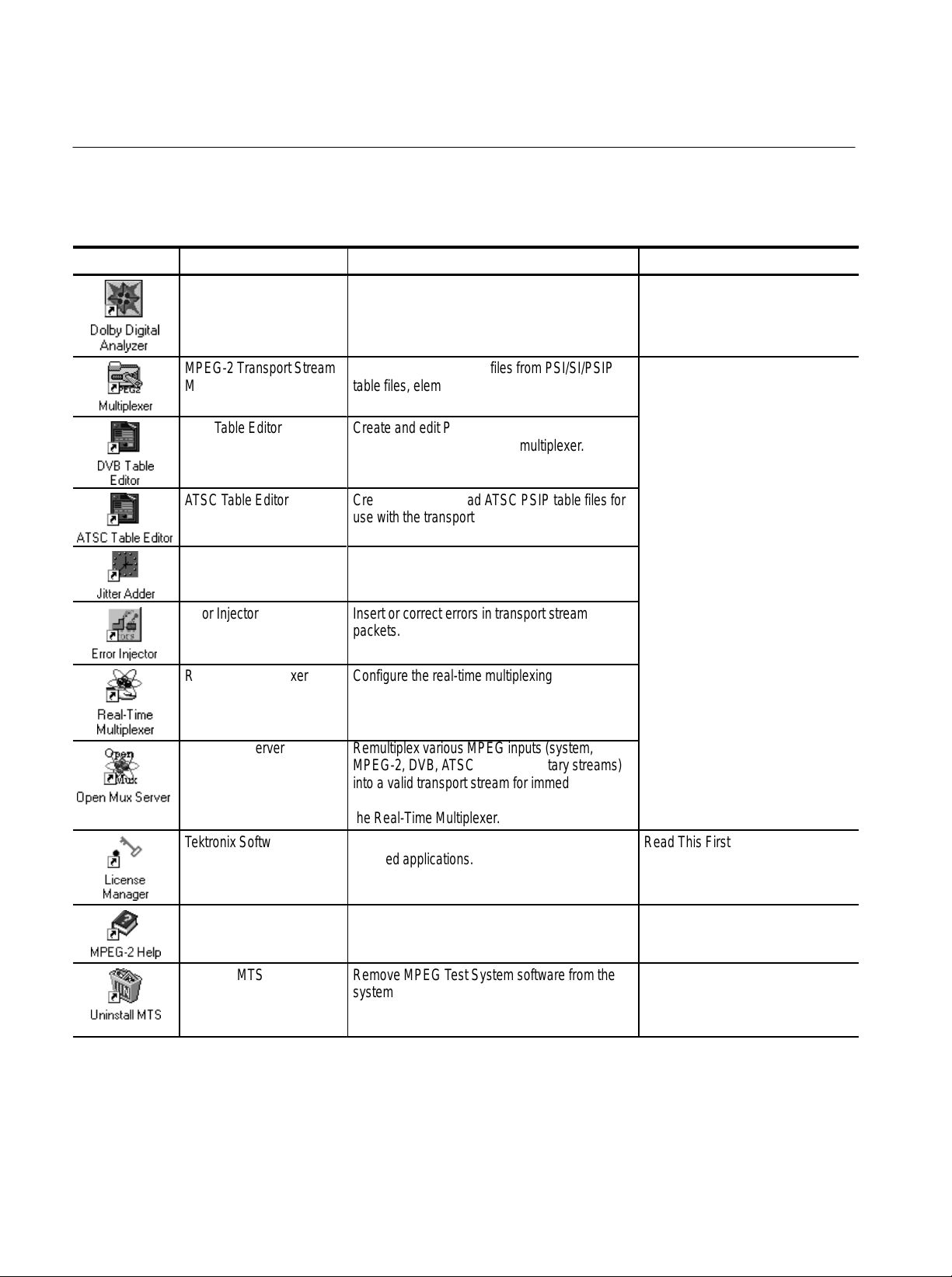
T able i: MPEG Test System version 3.0 applications (Cont.)
Icon User DocumentFunctionApplication title
Dolby Digital Audio Stream
Analyzer
Analyze Dolby Digital (AC-3) audio elementary
stream files or streams extracted from the
MPEG-2 DVB/A TSC System Analyzer.
MTS200 Dolby Digital Audio
Stream Analyzer User Manual
071-0535-XX
MPEG-2 Transport Stream
Multiplexer
ББББББ
DVB Table Editor
ББББББ
ББББББ
ATSC Table Editor
ББББББ
Jitter Adder
ББББББ
ББББББ
Create transport stream files from PSI/SI/PSIP
table files, elementary stream files, and data
БББББББББББ
files.
Create and edit PSI and DVB SAI table files for
БББББББББББ
use with the transport stream multiplexer.
БББББББББББ
Create and edit PSI ad ATSC PSIP table files for
БББББББББББ
use with the transport stream multiplexer.
Add jitter to PCR data in MPEG-2 transport
БББББББББББ
stream files.
БББББББББББ
Error Injector Insert or correct errors in transport stream
packets.
Real-Time Multiplexer Configure the real-time multiplexing application
to remultiplex system and or elementary streams
for immediate output.
Open Mux Server Remultiplex various MPEG inputs (system,
MPEG-2, DVB, ATSC, and elementary streams)
into a valid transport stream for immediate
output. The user interface for this application is
the Real-Time Multiplexer .
T ektronix Software
Protection
Enter or reenter the general password to enable
licensed applications.
MTS200 S
tions User Manual 071-0534-XX
ББББББББ
ББББББББ
ББББББББ
ББББББББ
ББББББББ
ББББББББ
ББББББББ
ББББББББ
ББББББББ
ББББББББ
Read This First, MTS200 Software
V3.0 071-0537-XX
MPEG2_Part1
(ISO/IEC13818-1)
Uninstall MTS Remove MPEG T est System software from the
x
The international MPEG-2 system standard in
Windows Help format.
system disk.
MTS 200 Series MPEG Test System Data Store Administrator
none
MTS200 User Manuals
Page 15

Software Version
Á
ÁÁÁÁ
Á
Á
Á
Á
Table ii lists the MTS 200 MPEG Test System application version numbers
supported by this manual. To verify an application version number, select Help
in the application menu bar; then select About from the Help menu.
Table ii: MTS200 MPEG Test System (V3.0) supported applications
Preface
Supported
Application
Data Store Administrator
БББББББ
version
V2.0 and
above
Contacting Tektronix
ÁÁ
Applicable document(s)
MTS200 Series MPEG Test System Data Store Administrator User Manual
ББББББББББББББББББ
Product
Support
For application-oriented questions about a Tektronix measurement product, call toll free in North America:
1-800-TEK-WIDE (1-800-835-9433 ext. 2400)
6:00 a.m. – 5:00 p.m. Pacific time
Or contact us by e-mail:
tm_app_supp@tektronix.com
For product support outside of North America, contact your
local Tektronix distributor or sales office.
Service
Support
Contact your local Tektronix distributor or sales office. Or visit
our web site for a listing of worldwide service locations.
Manual
part number
071-0536-XX
ÁÁ
www.tektronix.com
For other
information
In North America:
1-800-TEK-WIDE (1-800-835-9433)
An operator will direct your call.
To write us Tektronix, Inc.
P.O. Box 1000
Wilsonville, OR 97070-1000
MTS 200 Series MPEG Test System Data Store Administrator
xi
Page 16

Preface
xii
MTS 200 Series MPEG Test System Data Store Administrator
Page 17

Getting Started
All Tektronix MTS 210 and MTS 215 MPEG Test Systems contain the Data
Store system, which can acquire and output transport streams at rates from
1 Mbit/s to 60 Mbit/s (maximum) and store up to 18 Gbytes of data. At the
highest data rate, the Data Store system can store over 40 minutes of transport
stream data; you can also use end-to-start looping to continuously (and indefinitely) acquire or output transport stream data.
This section contains information to help you get started using the Data Store
Administrator, the application that controls and manages the Data Store system.
Refer to the following subsections as necessary:
H Input and Output Connections, page 2
H First Time Operation, page 9
H Software Repair, page 12
Refer to the Operating Basics section, beginning on page 13, for information
about using the Data Store Administrator.
MTS 200 Series MPEG Test System Data Store Administrator
1
Page 18

Getting Started
Input and Output Connections
Figure 1 shows the test system Data Store input and output (I/O) connectors on
the Compaq Proliant rear panel. Figure 2 shows the same connectors on the
Compaq Prosignia rear panel (MPEG Test Systems with serial numbers below
B040000). A detailed description of each connector follows the illustrations. Use
the I/O port(s) best suited to your signal sources and operating environment.
For I/O port specifications, refer to Specifications beginning on page 49.
ECL parallel/serial
I/O port
ECL control port
Figure 1: Data Store inputs and outputs (Compaq Proliant)
TTL 50 W serial
port (Clk I/O)
TTL 50 W serial
port (Data I/O)
External clock
input (Clk In)
10 Mbit serial I/O
port (RS-422
levels)
G.703 input
G.703 output
(34.368 Mbits/s)
G.703 output
(8.448 Mbits/s)
ECL Parallel/Serial I/O Port
2
The ECL Parallel/Serial I/O port receives and transmits MPEG-2 transport
streams at ECL levels. The port is differential, bidirectional, and operates
independently or in conjunction with the ECL Control port. The port transmits or
receives either parallel or serial data depending on the Data Store Administrator
application settings.
ECL Operating Modes. If the ECL Parallel/Serial I/O port is used independently
of the ECL Control port, there are three basic operating modes:
H Slave acquisition mode. Captures input signals using the ECL Parallel/Serial
I/O port clock signal as the timing source.
MTS 200 Series MPEG Test System Data Store Administrator
Page 19

Getting Started
H Master generation mode. Outputs signals using the test system internal clock
as the timing source.
H Master generation with external clock mode. Outputs signals using the
external clock input (Clk In) as the timing source.
Using the ECL Parallel/Serial I/O port in conjunction with the ECL Control port
provides the following additional operating modes:
H Master acquisition mode. Captures input signals using control signals from
the ECL Control port to drive the signal source.
H Master acquisition with external clock mode. Same as above but uses a
timing signal from the external clock input (Clk In) as the timing source.
H Slave generation mode. Outputs signals using the ECL Control port inputs as
the timing source.
NOTE. A Master generates the data transmission clock. A Slave returns an
external clock as the source.
ECL control port
G.703 input
G.703 output
(34.368 Mbits/s)
G.703 output
(8.448 Mbits/s)
Figure 2: Data Store inputs and outputs (Compaq Prosignia)
7
ECL parallel/serial
I/O port
6
10 Mbit serial I/O
port (RS-422
5
4
3
levels)
External clock
input (Clk In)
TTL 50 W serial
port (Data I/O)
TTL 50 W serial
port (Clk I/O)
2
1
MTS 200 Series MPEG Test System Data Store Administrator
3
Page 20

Getting Started
3
5
5
5
3
5
5
5
T able 1: ECL Parallel data pinout
ECL parallel pinout Pin Function Pin Function
1 DCLK 14 DCLK
1
2
4
6
7
8
9
10
11
12
13
Asserted Low differential signal.
2 Ground 15 Ground
14
3 DA TA 7 16 DATA 7
1
4 DA TA 6 17 DATA 6
16
17
5 DA TA 5 18 DATA 5
18
6 DA TA 4 19 DATA 4
19
7 DA TA 3 20 DATA 3
20
8 DA TA 2 21 DATA 2
21
21
9 DA TA 1 22 DATA 1
22
23
10 DA TA 0 23 DATA 0
24
11 DV ALID 24 DV ALID
2
12 PSYNC 25 PSYNC
13 Shield
T able 2: ECL Serial data pinout
ECL serial pinout Pin Function
1 DCLK
1
2
4
6
7
8
9
10
11
12
13
Asserted Low differential signal.
2 Ground
14
3 thru 9 Not managed
1
10 DA TA 0
16
17
11 DVALID
18
12 PSYNC
19
13 Shield
20
14 DCLK
21
21
15 Ground
22
23
16 thru 22 Not managed
24
23 DA TA 0
2
24 DVALID
25 PSYNC
4
MTS 200 Series MPEG Test System Data Store Administrator
Page 21

Getting Started
5
ECL Control Port
G.703 Output
(8.448 and 34.368 Mbit/s)
and G.703 Input
The ECL Control port is optional. This bidirectional differential control port
adds flexibility to the ECL Parallel and Serial Ports, providing three control
signals and two more operating modes.
T able 3: ECL Control data pinout
ECL control pinout Pin Function
1 CHCLK (channel clock)
2 Ground
1
2
2
3
4
Asserted Low differential signal.
3 CHSYNC (channel sync)
6
4 CHCLKEN (channel clock enable)
7
5 Shield
8
6 CHCLK (channel clock)
9
7 Ground
8 CHSYNC (channel sync)
9 CHCLKEN (channel clock enable)
The G.703 serial interface complies with the electrical characteristics of ITU-T
Recommendation G.703 (HDB3 code) for 8.448 Mbit/s and 34.368 Mbit/s.
The G.703 port operates in the following modes:
H Acquisition mode. Locks to the incoming signal and is self clocking.
H Generation (internal clock source) MODE. Uses an internal clock source.
The G.703 serial interface uses three Data Store circuit-board mounted SMB
connectors. One connector is a dedicated input for both bit rates. The other two
connectors are dedicated outputs, one for the 34.368 Mbit/s output and the other
for the 8.443 Mbit/s output. To reduce spurious emissions, connect only the
output in use.
NOTE. Do not leave SMB-to-BNC adapter cables on unused G.703 outputs.
Doing so will cause the test system to exceed EMC emission requirements.
MTS 200 Series MPEG Test System Data Store Administrator
5
Page 22

Getting Started
5
10 Mbit Serial Port
(RS-422 Levels I/O Port)
The 10 Mbit Serial port transmits and receives MPEG transport signals and
includes bidirectional clocks and data pairs. The maximum operating frequency
is 10 Mbit/s. The port uses RS-422 voltage levels with a line-to-line input
termination of 110 W.
T able 4: 10 Mbit Serial data pinout
10 Mbit serial pinout Pin Function
1 DA TA IN
2 CLK IN
1
2
2
3
4
Asserted Low differential signal.
3 DA TA OUT
6
4 CLK OUT
7
5 Ground
8
6 DA TA IN
9
7 CLK IN
8 DA TA OUT
9 CLK OUT
The 10 Mbit Serial port uses the following signals:
Clock Input
H Data In and Data Out (MPEG serial bit streams).
H Clock In and Clock Out (continuous data transmission).
The 10 Mbit Serial port operates in the following modes:
H Acquisition mode. Captures an input signal using an external timing
reference.
H Internal generation mode. Generates an output signal using the MPEG Test
System internal clock as the timing reference.
H External generation mode. Generates an output signal using the Clock input
as the timing reference.
The Clk In connector provides an optional timing input for the ECL Serial, ECL
Parallel, TTL, and 10 Mbit Serial outputs. The input operates at a maximum
frequency of 45 MHz.
For example, a 45 MHz clock input can generate a 45Mbit/s serial ECL signal. A
45 Mbit/s ECL output requires a 5.624 Mbit/s (byte-wide) clock input.
6
MTS 200 Series MPEG Test System Data Store Administrator
Page 23

Getting Started
TTL 50 W Serial Port
(Data & Clock I/O)
Data Store I/O Cables and
Mating Connectors
The TTL 50 W Serial Port consists of dedicated clock and data inputs that
transmit and receive at TTL levels. The Data signal is a serial bitstream that uses
a continuous data transmission clock. The maximum operating frequency is
45 Mbits/s.
The
TTL 50 W Serial Port operates in the following modes:
H Acquire mode. Captures an input signal.
H Internal Generation mode. Generates a signal locked to the internal clock.
H External Generation mode. Generates a signal locked to an external reference
supplied by the Clock Input.
The MPEG Test System includes adapters to connect the Data Store SMB
connectors to standard BNC connectors. You may also need to acquire or
assemble other signal-connecting cables and adapters to install the test system in
your facility.
Cable Lengths. Maximum cable length is a function of data rate, cable type, and
ambient environment as summarized in Table 5. In general, low data rates
tolerate longer cable lengths than do high data rates. Low-loss coaxial cable and
low capacitance properly pair-twisted cable support longer transmission paths
than do miniature coaxial cable or ribbon cable. Induced RF noise can further
limit usable cable length.
The only test system ports designed for data transmission are the G.703 I/O
ports. All other ports are intended for short-range interconnects. With most ports,
you must control cable delay matching to maintain clock-to-data timing margins
or data integrity will suffer.
T able 5: Estimated maximum cable lengths
Port Data Rate
(Mbits/s)
G.703 8.448 275 Belden 8281 4 dB atten at
G.703 34.368 125 Belden 8281 4 dB atten at
10 MBit
(RS422)
10 MBit
(RS422)
TTL 10 50 RG58 type Calculated Value
1 100 24 AWG
10 15 24 AWG
Maximum length
(meters)
Cable type Comments
4.224 MHz
17.18 MHz
Ref. ANSI/TIA/
unshielded
twisted pair
unshielded
twisted pair
EIA-422-B-1994
Ref. ANSI/TIA/
EIA-422-B-1994
MTS 200 Series MPEG Test System Data Store Administrator
7
Page 24

Getting Started
T able 5: Estimated maximum cable lengths (cont.)
Software Key
Port CommentsCable typeMaximum length
TTL 50 25 RG58 type Calculated Value
ECL Parallel 1 50 Belden 8112 Calculated Value
ECL Serial 45 5 Belden 8112 Calculated Value
Data Rate
(Mbits/s)
(meters)
Adapters. The MPEG Test System includes six SMB-to-BNC adapter cables.
Three of the adapter cables match the impedance of the G.703 75 W inputs and
outputs. The other three match the impedance of the TTL 50 W Serial Port
(CLK I/O, DATA I/O, and CLK IN).
The Rainbow Technologies software key, or Dongle, is not required to run the
Data Store Administrator; however, it must be installed on the computer parallel
port to start and run most other Tektronix MPEG Test System applications.
NOTE. The software key that matches your system must be installed on the
parallel port to start and run most MTS 200 Series software applications. Do not
remove or misplace the software key. Do not exchange the software key with the
key from another Tektronix MPEG Test System.
8
MTS 200 Series MPEG Test System Data Store Administrator
Page 25

First Time Operation
Getting Started
To power on the test system computer, slide the power switch cover plate to the
right and press the power switch.
Slide power switch
cover plate
Power switch
The Windows NT initialization process takes up to two minutes to complete.
Under normal circumstances, no action is required. (For further information on
the Windows NT initialization process, see the Windows NT documentation
included with the test system.) When the Begin Logon window appears,
simultaneously press the
CTRL + ALT + DELETE keys to open the Logon Informa-
tion dialog box.
Logging On
To log on to the test system, enter MTS100 in the User name box, leave the
Password box blank, and press
factory). Use this logon for most of your work.
There are two other logons and passwords available. The first is guest with no
password. This level has only limited access to files and applications. The
second level is administrator with MPEG2 as the password. This user has
MTS 200 Series MPEG Test System Data Store Administrator
ENTER (these are the default values set at the
9
Page 26

Getting Started
administrator privileges. You must use this logon when performing all software
upgrades.
CAUTION. The administrator user logon includes all privileges. If you are
connected to a network, you may have special privileges within the network. Do
not use this logon to perform normal operations.
Changing Passwords. You can change passwords at this time. See the Windows NT documentation for instructions. If you change any password, be sure to
create a new emergency repair disk. See page 12 for additional information.
Starting the
Data Store Administrator
When logon is complete, the Tektronix MPEG Test System program group
window appears as shown below. Double-click the Data Store Administrator
icon to start the program. Refer to the Operating Basics section, beginning on
page 13, for information about using the Data Store Administrator.
Refer to the appropriate User manual for information about other MPEG Test
System applications. Refer to Related Documents and Related Applications, both
in the Preface of this manual, for the correct manual title and part number.
NOTE. Although Windows NT permits several applications to run simultaneously,
hardware limitations prevent simultaneous use of the Deferred-Time Analyzer or
Multiplexer with the Data Store Administrator.
10
MTS 200 Series MPEG Test System Data Store Administrator
Page 27

Getting Started
Exiting the Data Store
Administrator
Shutting Down the
Computer
To exit Data Store Administrator, select Exit/Quit from the application File
menu or click the close button in the upper-right corner of the application
window.
Close
button
To avoid loss of data and possible problems during subsequent Windows NT
initialization, always shut down Windows NT before switching computer power
off. To shut down Windows NT, select Shut Down from the Start menu.
In the Shut Down Windows dialog box, select Shut down the computer? and
then click Yes. After a few seconds, the Shutdown Computer window appears
with the message “It is now safe to turn off your computer.” You can now power
off the computer.
CAUTION. Do not switch computer power off before the message “It is now safe
to turn off your computer” appears. Doing so may result in lost data and
difficulty in restarting Windows NT.
MTS 200 Series MPEG Test System Data Store Administrator
11
Page 28

Getting Started
Software Repair
If you experience operating problems and suspect that one or more MPEG Test
System files have been corrupted, refer to the Software Repair appendix in either
of the following manuals:
The MTS200 Series MPEG-2 DVB/ATSC System Analyzer User Manual,
Tektronix part number 071-0532-XX.
The MTS200 Series Stream Creation Applications User Manual, Tektronix part
number 071-0534-XX.
12
MTS 200 Series MPEG Test System Data Store Administrator
Page 29

Operating Basics
Terms
The Data Store Administrator application manages the Data Store disks and
MPEG-2 transport stream acquisition and generation to and from the disks.
Because Windows NT cannot manage the Data Store disks, the Data Store
Administrator performs all the low-level functions normally accomplished with
the Windows NT Explorer application.
The Data Store Administrator, the SCSI drivers, and the EISA card are optimized
to provide a continuous data acquisition or generation rate of up to 60 Mbits/s
(ECL) for a minimum of 40 minutes (18 Gbyte data store disk capacity) without
interruption or data loss. Looping acquisition and generation is also possible.
The terms Data Store disk and system disk are NOT interchangeable. CARB is a
French acronym that is synonymous with Data Store.
Data Store Disk. The Data Store disks are four hard drives totalling 18 Gbytes
that are physically connected to the Data Store circuit board. These disks are
used by the Data Store Administrator when generating and acquiring transport
streams. They can also be used by the following applications when dealing with
files that are too large for the system disk: Multiplexer, DVB/ATSC System
Analyzer, Audio stream Analyzer, Video stream Analyzer, Program Stream
Analyzer, and Dolby Digital Audio analyzer.
System Disk. The system disk is the fixed disk drive (hard disk) that contains the
Windows NT operating system files and the MTS200 Series application
software. You can access this disk using the Windows NT Explorer application.
The system disk is configured during manufacture as the C drive.
CARB. The term CARB, a French acronym referring to the Data Store disks or
the Data Store board, is used often in the Data Store Administrator user interface.
CARB appears in this manual when necessary to reflect on-screen nomenclature
and to avoid ambiguity.
MTS 200 Series MPEG Test System Data Store Administrator
13
Page 30

Operating Basics
Special Features of the Data Store Disks
In order to generate or acquire MPEG-2 transport streams, the Data Store disks
have these special features required to accommodate constant, high bit rate
input/output:
H The data store disks can be divided into single shot and looping partitions.
H The Single Shot partition can contain up to 255 files. File acquisition must
stop when the partition is full.
H The looping partition permits continuous capture of input, which is stored as
a single file. If you create a six Gbyte looping partition, you can fill the
partition and continue acquisition. The partition always contains the most
recently acquired data. After you stop acquisition you can analyze or replay
the last six Gbytes of input.
Each new acquisition to the looping partition overwrites any previously-acquired data. You can store only one file on the looping partition.
H You can output any file from either partition repeatedly in looping mode.
H You can partition the Data Store disks as entirely single shot, entirely
looping, or any combination between those two extremes (for example,
16 Gbytes single shot and 2 Gbytes looping).
H You can change the relative sizes of the partitions at any time; however,
repartitioning the Data Store disks erases all files on the disks. Refer to
Partitioning the Disks on page 19 for more information.
H In order to sustain extremely high rates of data transfer, the Single Shot
partition uses a rigid file structure. Unlike a normal computer disk, on which
file data can be fragmented and stored wherever there is free space, the Data
Store disks must store each file as a single data block immediately “below”
the last-acquired file. As a result, you cannot simply delete an arbitrary file
to free up disk space. This is explained further under Compress Disks on
page 40.
NOTE. Because of the rigid file structure, it is strongly advised that you use the
Data Store disks only for acquiring, storing, and generating transport stream
files. For best results, always transfer small files onto the MTS200 Series system
disk for long-term storage.
14
MTS 200 Series MPEG Test System Data Store Administrator
Page 31
Starting the Application
Acquiring Data
Operating Basics
There are two ways to start the application:
H Double-click the Data Store Administrator icon in the Tektronix MPEG
Test System program group window.
H Select Data Store Administrator from the Programs/Tektronix MPEG Test
System submenu of the Windows NT Start menu.
NOTE. You cannot start the Data Store Administrator application if either the
Deferred-Time Analyzer or the Multiplexer applications are running.
Follow this outline procedure to receive and save data on the Data Store disks.
1. Connect the data source to the appropriate Data Store system input. For
descriptions of the inputs, refer to Appendix A: Data Store I/O Specifications
or Getting Started in the MTS 200 Series Hardware Installation and
Specifications Compaq Proliant 1600 Platform Technical Reference,
Tektronix part number 071-0261-XX.
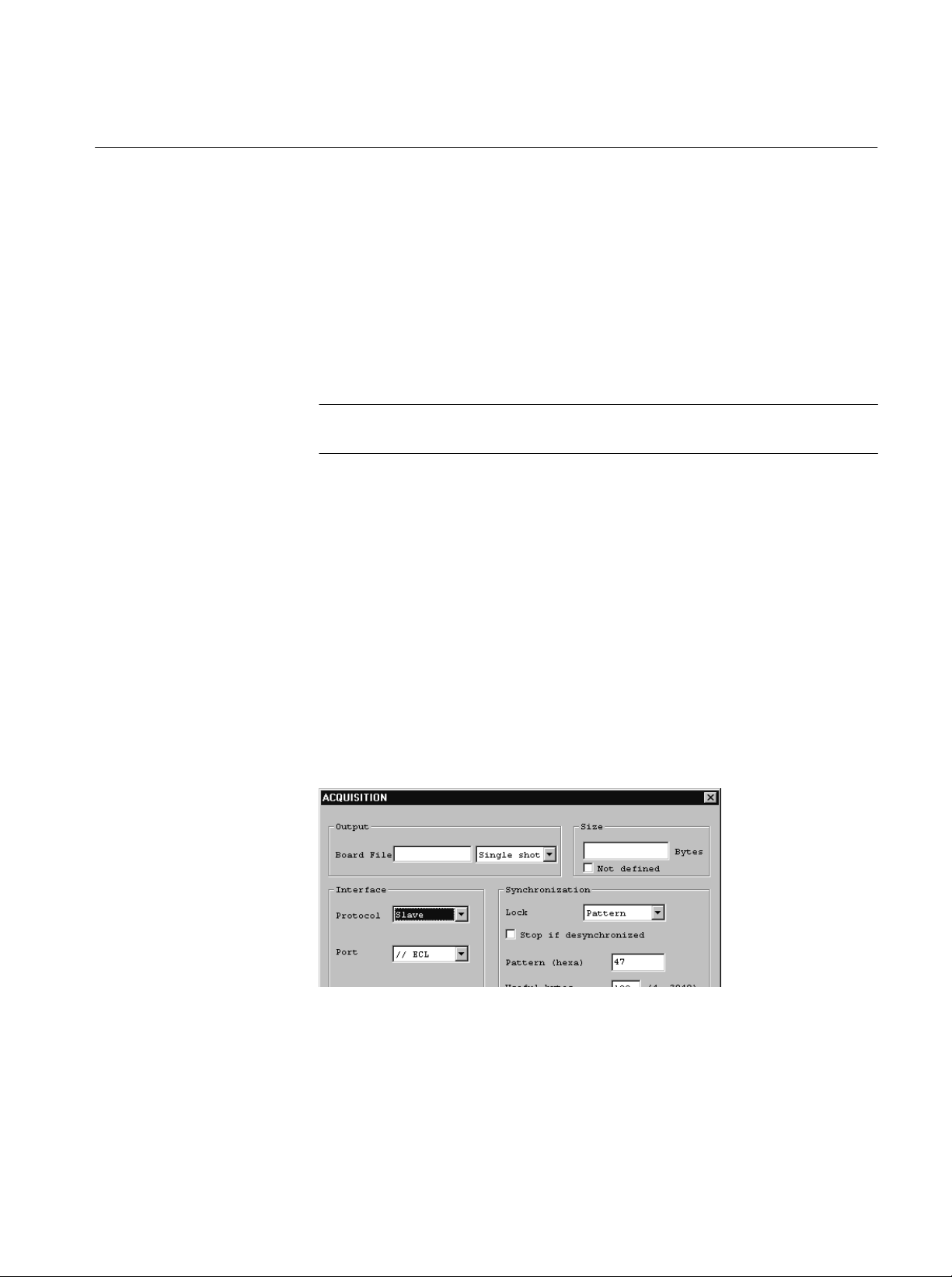
2. Click the A (acquisition) command button to open the ACQUISITION
settings window.
3. Enter a name for the file to be saved in the Board File text box. If you intend
to analyze the file with the Deferred-Time Analyzer, use an appropriate file
name extension (*.trp, for example).
4. If the Data Store disks have both a Single Shot and a Loop partition, select
the target partition.
MTS 200 Series MPEG Test System Data Store Administrator
15
Page 32

Operating Basics
5. Enter a size to specify how much of the input stream to capture; select Not
defined if you intend to stop acquisition manually (such as when capturing
indefinitely to the Loop partition).
6. Select Slave protocol to use the source clock; select Master protocol to use
the internal Data Store clock.
7. Select the input port. Choices depend on the following protocol selection:
H Inputs available with Slave protocol: //ECL, Serial ECL, G703, TTL,
and 10 Mbits.
H Inputs available with Master protocol: //ECL and Serial ECL.
8. Depending on the port selection, you may have additional Interface choices.
Refer to Acquisition on page 31 for further information.
9. Select the appropriate Synchronization settings. To acquire an MPEG-2
transport stream made up of 188 byte packets, use the settings (Pattern/47/188) shown in the example ACQUISITION window above. Refer to
Acquisition on page 31 for further information.
10. Click Start. If the settings are correct for the input, the Acquisition in
progress message appears in the application window.
11. If you defined a file size, acquisition ends when the specified amount of data
is received. Otherwise, select Interrupt Transfer from the Acq/Gen menu
or click the corresponding (red hand) command button to stop acquisition.
In the default configuration, the Data Store Administrator dialog box
containing the message “Transfer is finished” appears after each acquisition
of a specified size. Click OK to acknowledge the message. You can edit the
Windows NT registry to prevent appearance of this message; refer to
Suppressing the “Transfer is Finished” message on page 43 for instructions.
When acquisition ends, the new file is added to the File information list.
16
MTS 200 Series MPEG Test System Data Store Administrator
Page 33

Generating (Outputting) Data
Follow this outline procedure to output data from the Data Store disks. You can
refer to Generation, beginning on page 35, for additional information.
1. Select a file from the File information list and right-click to open the
shortcut menu.
2. Click Generation to open the GENERATION settings window.
Operating Basics
3. Make the following selections:
T able 6: Data Store generation settings
Settings parameter Choices/explanation
Loop Select to repeatedly output entire file
Size Portion of the file to output once. Not available when loop is selected
Offset Bytes at the beginning of file to ignore. Not available when loop is
selected.
Protocol Master or Slave
Port //ECL, Serial ECL, G703, TTL, 10 Mbits
MTS 200 Series MPEG Test System Data Store Administrator
17
Page 34
Operating Basics
T able 6: Data Store generation settings (Cont.)
Settings parameter Choices/explanation
Output clock Depends on Port; see Table 12 on page 37.
Frequency Depends on Port and clock; see Table 12 on page 37.
Msb first Available with serial ports only and if Data Store system is configured;
refer to Msb first on page 37 for additional information.
Control signals Available with ECL ports only, forces burst mode output
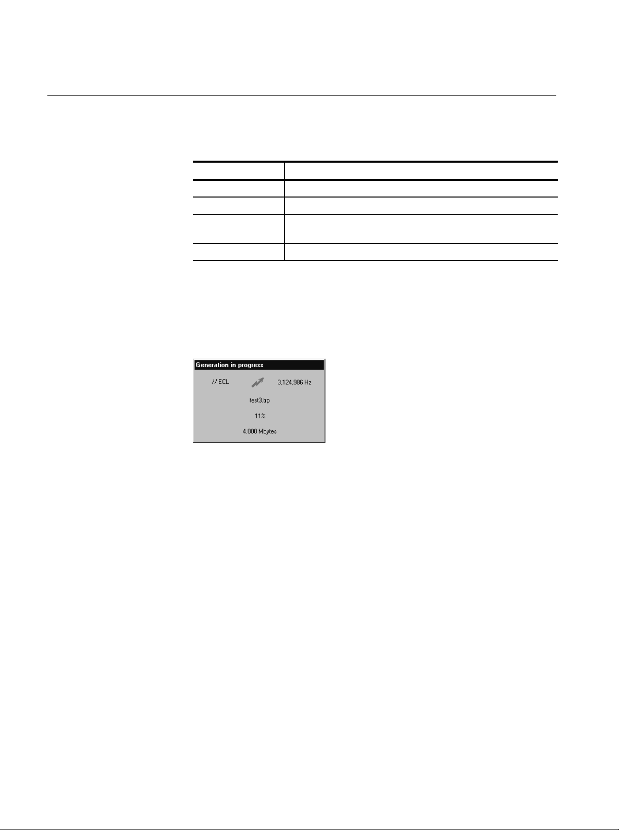
4. Click Start. The Generation in progress message appears and remains on the
Data Store Administrator application window as long as generation
continues. You can minimize the application window during generation, but
you cannot exit the Data Store Administrator.
Disk Management
5. If you selected Loop generation, select Interrupt Transfer from the
Acq/Gen menu or click the corresponding (red hand) command button to end
generation. Otherwise, generation ends when the end of the source file is
reached.
In the default configuration, the Data Store Administrator dialog box
containing the message “Transfer is finished” appears after each one-time
(not looping) generation. Click OK to acknowledge the message. You can
edit the Windows NT registry to prevent appearance of this message; refer to
Suppressing the “Transfer is Finished” message on page 43 for instructions.
The Data Store system hardware and software is specially designed for unusually
high rates of data transfer. As a result, you cannot use standard Windows NT file
management practices to manage the Data Store disks. Although the Data Store
system is visible as folder C:\Carb0 through the My Computer icon and the
18
MTS 200 Series MPEG Test System Data Store Administrator
Page 35

Operating Basics
Windows NT Explorer application, you can copy, output, and erase Data Store
files only through the Data Store Administrator application.
Partitioning the Disks
The Data Store disks can have two types of partition:
H Single Shot, for acquisition and storage of up to 255 individual files.
Acquisition can continue only until the partition is full.
H Looping, for continuous acquisition of a single file. When the partition is
full, new input data overwrites the oldest data on the partition.
You can partition the Data Store disks as entirely Single Shot, entirely Looping,
or any combination between the two extremes (for example, 16 Gbytes single
shot and 2 Gbytes looping).You can change the relative sizes of the partitions
whenever the Data Store system is not generating or acquiring; however,
repartitioning the Data Store disks erases all files on the disks.
CAUTION. Partitioning the Data Store disks erases all file directory information
and makes it impossible to read, retrieve, or use previously-stored data. Be sure
to transfer irreplaceable and important files to the system disk or other storage
media before partitioning the Data Store disks.
Use the following procedure to partition the Data Store disks:
1. Transfer all important Data Store files to the System Disk or to another
MPEG Test System. Refer to Copying Files to the Computer on page 20 or
Data Store Transfers on page 44 for instructions and additional information.
2. Select Partition Disks from the Service menu. The Partitionning window
opens.
3. Select the appropriate Partition type from the list.
MTS 200 Series MPEG Test System Data Store Administrator
19
Page 36

Operating Basics
4. If you selected only Single shot or only Loop partition type, click OK to
create the partition.
5. If you selected Single shot & loop, enter the desired size of the loop partition
and click OK to create the partitions.
6. Click Yes in the resulting Are you sure? message window to confirm your
choice (click No to abort partitioning).
When partitioning is complete, the Disk information reflects your partitioning choices and the File information list is empty.
Copying Files
from the Computer
You can copy files to the Single Shot partition from any drive that the computer
has access to, such as the system disk, the CD ROM drive, and any network
drives. Use the following procedure to copy files from MPEG Test System disks
to the Data Store disks:
1. Check the Single Shot partition Disk information to verify that the Available
size is large enough for the file.
2. Select PC to Board (Write) from the File menu or click the W command
button. The File Write to CARB window opens.
3. Click Browse to open a standard Windows Open dialog box.
4. Locate and select the appropriate file (double-click on the file name or click
OK to dismiss the Open dialog box).
By default, the PC file name is used as the name of the Data Store file. You
can edit the name in the Name of the CARB File text box.
20
Copying Files
to the Computer
5. Click Start to begin writing the file onto the Single Shot partition. A
message box appears to show the progress of the operation. Another box
appears when the transfer is complete; click OK to acknowledge. The file
name appears at the bottom of the Single Shot partition files list.
You can copy files from either Data Store partition to any drive that the computer
has access to, such as the system disk and network drives. Use the following
procedure to copy files from the Data Store disks to MPEG Test System disks:
1. Verify that there is enough room on the target drive to accept the file. (To
check disk free space, open the My Computer window and click on the target
MTS 200 Series MPEG Test System Data Store Administrator
Page 37

Operating Basics
drive icon; the disk free space is reported on the status bar at the bottom of
the window.)
NOTE. Due limitations of the File Allocation Table (FAT) file system, you cannot
copy files larger than four Gbytes onto the system disk.
2. Highlight the name of the source file on the Data Store Administrator File
information list.
3. Right-click to open the shortcut menu; then click Read.
The File Read from CARB window opens.
4. To copy the entire file under its original name in the C:\Mts200\Cfg-trp
directory, click Start.
5. To copy the file to a different directory and file name, enter the path and
name in the Name of the PC file text box or click Browse to access the
appropriate drive and directory and enter the file name.
6. To copy only a portion of the file, enter the desired size in the Size box. If
you enter 20000000 (or 20,000,000 or 20 000 000), for example, only the
first 20 Mbytes of the file will be written to the PC disk. To copy only
packets 11 through 110 from a stream of 188-byte packets, enter 1880 in the
Offset box and enter 18800 in the size box.
MTS 200 Series MPEG Test System Data Store Administrator
21
Page 38

Operating Basics
Erasing All Files
Erasing Files to Increase
Available Disk Space
To quickly erase all files from both partitions of the Data Store disks, choose Fat
Delete from the service menu. The “Are you sure?” message appears. To delete
all files from the Data Store disks, click Yes.
CAUTION. The Fat Delete command is irreversible. You cannot recover deleted
files. Never use the Fat Delete command before confirming that important Data
Store files have been backed up on the system disk or on other media.
In some circumstances, you may want to delete some files from the Data Store
disks in order to make room for additional acquisitions while preserving other
important files that may be too large to transfer to the system disk. Because Data
Store files must occupy contiguous regions of the disks, you must first mark the
unwanted files for deletion and then compress the disks to create the largest
possible segment for new acquisitions.
1. Delete unwanted files as follows:
a. Select the unwanted files on the File information list.
To select several files in a row, hold the
SHIFT key down while making
your selections; to select several files that are not listed consecutively,
hold the
CTRL key down while making your selections.)
b. Right-click to open the shortcut menu. If you have selected more than
one file, Delete is the only command available.
c. Click Delete. Click Yes or Yes to All in the resulting confirmation
window. Until you compress the disks, you can undelete all but the last
file on the list.
22
MTS 200 Series MPEG Test System Data Store Administrator
Page 39

Operating Basics
d. If you decide not to erase a file that is marked deleted, highlight the file
name and right-click; then click Undelete in the shortcut menu.
2. Compress the Data Store disks as follows:
a. To erase files that are marked deleted and to consolidate the remaining
files in contiguous regions of the data store disks, select Compress
Disks from the Service menu.
NOTE. The last file and files marked delete cannot be recovered following disk
compression.
b. One again the “Are you sure?” message appears. Click Yes to proceed.
NOTE. The Compress function requires approximately one second per megabyte
of disk space to compress the Data Store disks.
For example, 1 Gbyte = 1024 Mb; 1024 seconds is approximately 17 minutes.
c. When disk compression is complete, the File information list contains
only the names of the remaining files.
MTS 200 Series MPEG Test System Data Store Administrator
23
Page 40

Operating Basics
24
MTS 200 Series MPEG Test System Data Store Administrator
Page 41

Reference
This section contains detailed information about the Data Store Administrator.
The following subsections begin on the indicated pages:
H The Application Window, page 26
H Toolbar Command Buttons, page 26
H File Menu Commands, page 27
H Acq/Gen Menu Commands, page 31
H Service Menu Commands, page 38
H The Help Menu, page 43
H Suppressing the “Transfer is Finished” Message, page 43
H Data Store Transfers, page 44
H Problems/Troubleshooting, page 45
MTS 200 Series MPEG Test System Data Store Administrator
25
Page 42

Reference
The Application Window
Menu bar
Toolbar
When you open the Data Store Administrator, the application window shown
below occupies the screen.
Toolbar Command Buttons
The toolbar contains command buttons for several frequently used menu
commands. Click a button to select the corresponding menu command.
T able 7: Toolbar command buttons
Button Corresponding menu command
FAT Read (page 27)
Board to PC (Read) (page 28)
PC to Board (Write) (page 28)
Acquisition (page 31)
Generation (page 35)
Interrupt transfer (page 38)
26
MTS 200 Series MPEG Test System Data Store Administrator
Page 43

File Menu Commands
Á
Á
Á
Á
Reference
The File menu contains file management commands.
T able 8: File menu commands
Use To
FAT Read
FAT Read
Board to PC (Read)
List the files available on the Data Store disks
Copy a file from the Data Store disks to the system hard drive (or oth-
er disk)
PC to board (Write)
БББББ
Copy a file from the system hard drive or other media to the Data
ББББББББББББББББ
Store disks
Delete
БББББ
Undelete
Mark a Data Store file to be deleted (unless the file is at the bottom of
ББББББББББББББББ
the list, it can be undeleted any time before disk compression)
Remove the delete mark from a Data Store file
Exit Quit the Data Store Administrator application
FAT stands for File Allocation Table. The FAT Read command lists the files
available on the Data Store disks and shows their status. A FAT Read occurs
automatically when the Data Store Administrator is started and after most file
read and write operations.
MTS 200 Series MPEG Test System Data Store Administrator
27
Page 44

Reference
The FAT Information display occupies the application window and provides the
following information:
H Number of Disks detected on the Data Store board. There should be four
disks; any fewer indicates that you may have a malfunctioning disk. (The
MTS 200 Series can operate with fewer than four disks if one or more fails
and immediate replacements are not available.)
H Size of each disk (in bytes).
H Partition information.
H File name(s).
H File size(s) in bytes.
H Files marked as deleted (DEL). These files are deleted when the Compress
Disks command is next selected from the Service menu.
Board to PC (Read)
PC to Board (Write)
Use the Board to PC (Read) command to copy a file from the Data Store system
to the system disk (or another regular disk).
The most common reasons to copy a file to the system disk are as follows:
H To save an important file before repartitioning the Data Store disks.
H To save a file from the Loop partition before acquiring another file in
looping mode.
After selecting the name of the file to copy from the File information list, you
can invoke the read command in the following ways:
H Right-click in the File information box and then select Read from the
resulting shortcut menu.
H Press
CTRL+R.
H Click the R command button.
H Select Board to PC (Read) from the File menu.
Refer to Copying Files to the Computer on page 20 for step-by-step instructions.
The PC to board (Write) command copies a file from the system to the Data
Store disks. Use this command to move transport stream files created with the
Multiplexer application (or modified with the Packet Jitter or Coder/Decoder
applications) to the Data Store disks. After you move the files, you can use them
to generate transport streams.
28
MTS 200 Series MPEG Test System Data Store Administrator
Page 45

Reference
NOTE. It is not always necessary to use the PC to board (Write) command to
write files to the Data Store disks. You can write files directly to the Data Store
disks from the Multiplexer application using the c:\carb0\mono directory.
1. Select the PC to board (Write) command from the File menu, press
CTRL+W, or click the corresponding (W) toolbar button. The File Write to
CARB dialog box opens.
Delete
2. Enter the full path and file name or click Browse to select the file that you
want to transfer to the Data Store disks.
3. Enter an appropriate file name in the Name of the CARB File text box.
4. Click Start to copy the file onto the Data Store disks.
Use the Delete command to free up space on the Data Store disks.
To delete a file do the following:
1. Select the file(s) in the File information list.
2. Select Delete from the File menu or right-click to open the shortcut menu
and click Delete.
MTS 200 Series MPEG Test System Data Store Administrator
29
Page 46

Reference
3. The Confirm delete file warning message opens.
In most cases, you can undelete a file that is marked as deleted as long as
you have not compressed the Data Store disks (see page 40). However, if
you delete the last file (or files) in the FAT table, it (or they) will be removed
immediately. In this case, you are given a special warning that the file is not
recoverable.
Undelete
Use the Delete command to free up space on the Data Store disks. However, if
you remove files listed anywhere except at the end of the FAT, you must also
select the Compress Disks command from the Service menu (refer to Compress
Disks on page 40 for more information).
The Undelete command removes the (DELETED) mark from a file on the Data
Store disks. If you decide not to erase a file, use this command to return it to
normal status.
To undelete a file, highlight its name in the File information box. Select the
Undelete command from the File menu or right-click to open the shortcut menu
and click Undelete.
30
MTS 200 Series MPEG Test System Data Store Administrator
Page 47

Acq/Gen Menu Commands
Á
Á
Á
Á
The Acq/Gen menu gives you access to commands to acquire or generate
MPEG-2 transport streams.
T able 9: Acq/Gen menu commands
Use To
Reference
Acquisition
Acquisition
БББББ
Generation
БББББ
Interrupt transfer
Acquire a transport stream from the selected input port and save it as
ББББББББББББББББ
a Data Store file
Generate a transport stream from a transport stream file stored on the
ББББББББББББББББ
Data Store disks and outputs it from the selected output port
Stop the current Acquire or Generation process
Select the Acquisition command to open the ACQUISITION window. Use this
window to configure the Data Store system to acquire a transport stream and to
begin saving the stream to a file on the Data Store disks.
Some ACQUISITION window settings can affect the availability of other
settings and the appearance of the window can also change in response to your
choices.
MTS 200 Series MPEG Test System Data Store Administrator
31
Page 48

Reference
This section explains the following acquisition settings groups: Output, Size,
Interface, Synchronization, and Control Port (Master ECL Interface only).
Output. The Output group contains the Board File text box and a partition type
selection box. Enter a name for the file in which you will save the incoming
transport stream. If the Data Store disks have both a single shot and a loop
partition, then select the target partition from the list box.
NOTE. Use a Data Store File name that is not already in use or marked as
deleted.
Size. The Size group allows you to define the size of the file to be acquired. If
you want to leave the file size undefined, select the Not Defined check box. This
option allows the file to continue acquiring data until you select the Interrupt
transfer command (see page 38). If you do not select this check box, you must
enter a value in the text box. This number cannot be larger than the selected
partition size. When the MTS 200 Series has collected a file the same size as
defined in the text box, the acquisition process stops.
NOTE. The File Size must be greater than 1024 bytes.
Interface. The Interface group contains the Protocol, Port, Internal Clock, and
Frequency parameters.
The acquisition Protocol can be Slave or Master. If it is Slave, the input signal
supplies the clock; therefore, neither Internal Clock nor Frequency parameters
are available. If the Port is set to G.703, the clock frequency must be specified
however. If Protocol is set to Master, the Data Store board generates the clock.
Only the Parallel ECL and Serial ECL ports can have Master Protocol.
32
MTS 200 Series MPEG Test System Data Store Administrator
Page 49

Reference
The Port option selects the signal input port. The individual ports have their own
specifications. The following ports are available: //ECL (Parallel ECL), Serial
ECL, G.703, TTL (50 Ohm TTL), and 10 Mbit Serial Port (RS–422).
The Msb first option is available only when the Serial ECL port is selected.
Select Msb first to output each byte of data “most-significant bit” first.
The Internal Clock option, available with Master protocol, selects which of the
internal references is used as the clock. The following options are available:
PLL, Osc. 34.368 MHz, Osc. 8.448 MHz, and External Clock. If you select PLL,
the Frequency setting is available.
The Frequency setting should match the incoming signal rate. The available
frequency range is port dependent as specified in Table 10.
NOTE. Data rates for G.703 ports must be exact. Since PLL is unavailable, the
optional rates are 8.448 MHz or 34.368 MHz.
T able 10: Frequencies available for each port
Port Minimum frequency Maximum frequency
Parallel ECL
Serial ECL
G.703
TTL
10 Mbit Serial (RS422)
125 kHz
1 MHz
8.448 MHz
1 MHz
1 MHz
7.5 MHz
60 MHz
34.368 MHz
45 MHz
10 MHz
NOTE. Frequency step size is 1 Hz.
Synchronization. The Synchronization group determines how the incoming signal
locks. The options include: none, PSYNC signal, and Pattern. None and Pattern
are available to all ports. PSYNC is only available to the ECL ports.
If you are using a serial port and select None, synchronization is not guaranteed
to start at the beginning of a byte or packet. In this case, it is better to select the
pattern synchronization option.With Pattern synchronization, the first three
packets are lost however.
MTS 200 Series MPEG Test System Data Store Administrator
33
Page 50

Reference
If Pattern is selected as the lock mode, you must enter three additional parameters: Stop if Desynchronized, Pattern (hex), and Useful Bytes. If the Stop if
Desynchronized check box is selected, the acquisition stops with an error
message box after 8 bad synchronization bytes.
The Pattern is the actual synchronization signal in hexadecimal. For standard
transport packets, the sync byte is 47.
The Useful Bytes parameter is the size of the transport packet. The standard size
is 188.
The simultaneous presence of PSYNC and the synchronization pattern is not
verified. The PSYNC signal is only used to trigger the start of acquisition
(detection of the first leading edge). Thus no desynchronization criterion exists
in this case. After the start of acquisition, the presence of the PSYNC signal is
not verified.
The mechanisms of synchronization and loss of synchronization vary according
to the synchronization method used. See Table 11.
T able 11: How synchronization works
Synchronization method Acquisition begins with Loss of synchronization
None 1st clock received Never
By PSYNC signal 1 recognition Never
By pattern 3 exact recognitions Absence of exact recognition
during 8 cycles
34
MTS 200 Series MPEG Test System Data Store Administrator
Page 51
Reference
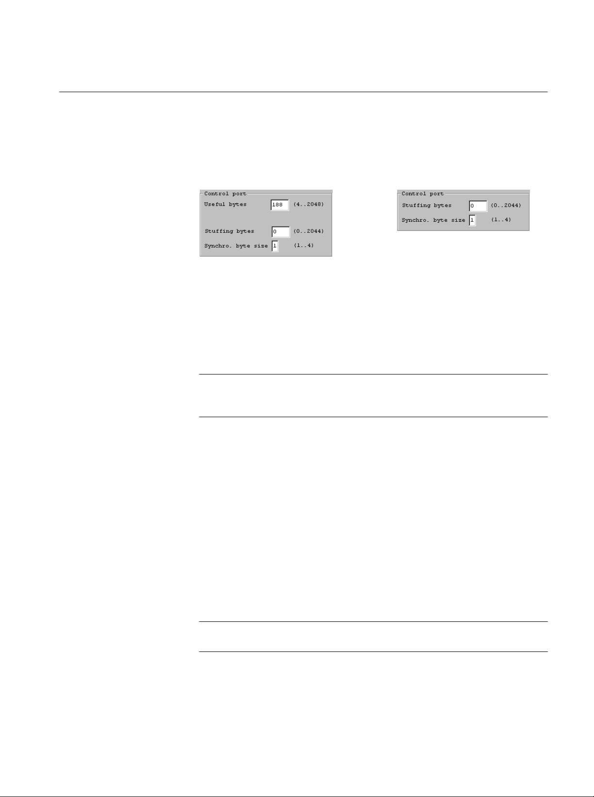
Control Port. If either of the ECL ports are in Master mode, an additional group,
Control Port, is presented. There are two or three parameters in this group,
depending on the Synchronization Lock type.
The Useful Bytes parameter is the number of useful bytes as validated by a
validation signal.
Stuffing Bytes is the number of bytes when the DEN (data enable) is off.
Synchro. Byte Size is the synchronization signal size, in bytes. It can range from
1 to 4 bytes.
Generation
NOTE. To prevent anomalous data, connect equipment only to those ports that
are in use. For example, for G.703 output, both G.703 ports are active at the
selected rate, but the voltage level is different on each port.
When a file name is selected in the File information list, the Generation
command opens the GENERATION settings window. You can configure the
Data Store system to generate a transport stream from the selected file and output
the stream through the specified port.
Use any of the following methods to open the GENERATION window:
H Right-click in the File information list; then click Generation on the
resulting shortcut menu.
H Click the G command button.
H Select Generation from the Data Store Administrator File menu.
NOTE. To open the GENERATION window, you must first select a Data Store file
from the File information list.
MTS 200 Series MPEG Test System Data Store Administrator
35
Page 52

Reference
The GENERATION settings window is dynamic in that the window contents
depend on some basic settings choices. The illustration above shows all possible
settings parameters. The parameters are discussed in the following paragraphs.
Source. The Board file is the file that you selected/highlighted on the File
information list before invoking the Generation command. If the correct file is
not selected, close the window and try again.
Loop. If Loop is checked, the Data Store system outputs the entire file continuously until you perform a manual interrupt. If it is not checked, the file is sent
only once. The Size and Offset settings are not available when Loop is selected.
NOTE. Minimum file size for looping generation is one Mbyte.
Size. Available only when Loop is not selected. By default, the Size text box
contains the size of the selected file. To output only a portion of the file, enter
the size in bytes. You can enter spaces or commas (example: 100 000 000 or
100,000,000) if desired. Unless you enter an Offset value, the Data Store system
begins output with the first byte of data in the file.
Offset. Available only when Loop is not selected. Enter the number of data bytes
to ignore at the beginning of the file. For example, to output the second 100 MB
of a 200 MB file, enter an Offset of 104 857 620.
36
MTS 200 Series MPEG Test System Data Store Administrator
Page 53

Reference
Protocol. The Protocol can be either Master (the Data Store board generates the
reference clock) or Slave (the clock is generated by an external source). Only the
ECL ports can use Slave protocol.
Port. Select the output port from the Port drop-down list. The choices are: //ECL
(Parallel ECL), Serial ECL, G.703, TTL (the TTL 50 Ohm port), and 10 Mbit
serial port (RS–422).
NOTE. Connect receiving equipment only to the selected output port. This will
prevent unexpected results.
All of the other parameters are based on the selected port. Table 12 summarizes
the availability of remaining settings parameters.
T able 12: Parameters available for each port selection
Port selection Osc. 8.448 MHz Osc. 34.368 MHz PLL Min – Max External clock Control signals
Parallel ECL
Serial ECL
G.703
TTL
10 Mbit Serial
N/A
Available
Available
Available
Available
N/A
Available
Available
Available
N/A
125 kHz – 7.5 MHz
1 MHz – 55 MHz
N/A
1 MHz – 45 MHz
1 MHz – 10 MHz
Available
Available
Available
Available
Available
Available
Available
N/A
N/A
N/A
Output clock. Depending on the port selection, the Output clock can be one of the
two internal oscillators (8.448 MHz or 34.368 MHz), the PLL, or an external
clock signal. If you select the PLL, the Frequency setting is available.
NOTE. The data rates for the G.703 ports must be exact. Therefore only the two
internal oscillators with the G.703 frequencies are available.
Frequency. Available only when PLL Output clock is selected. Enter the desired
frequency to the nearest Bit/s or Byte/s (select the appropriate units) within the
allowable range (see Table 12). Click the adjacent PCR button to have the Data
Store Administrator calculate the frequency from data in the output file.
Msb first. This option is available when the Serial ECL port is selected. Select the
Msb first option to output each byte of data “most-significant bit” first instead
of least-significant bit first, which is the default.
MTS 200 Series MPEG Test System Data Store Administrator
37
Page 54

Reference
Á
Á
Á
Á
Control signals. The Control signals option is available only with the ECL ports,
which have a DEN (data enable) signal. Selecting Control signals causes burst
mode output.
NOTE. If you select burst mode, be sure that the first byte(s) of the file are sync
bytes (SB), typically 0x47, because the SB signal is on during the first byte(s) of
the file.
The Nr useful bytes is the number of bytes when DEN is on.
The Nr stuffing bytes is the number of bytes when the DEN is off. All stuffing
bytes have the value entered in the Stuffing byte (hexa) text box.
The Synchro. signal size is the number of bytes when the SB (Sync Byte) signal
is on.
Interrupt Transfer
The Interrupt transfer command stops the current Acquisition or Generation
process.
Service Menu Commands
The Service menu contains housekeeping commands for the Data Store disks and
the Data Store board.
T able 13: Service menu commands
Use To
38
Board Reset
Resource Parameters
FAT Delete
БББББ
Partition Disks
БББББ
Perform a software reset on the Data Store board (use after an error)
View the Data Store resource parameters
Initialize the Data Store disks. The partitions are preserved, but all
ББББББББББББББББ
files are lost
Create disk partitions. Must be run each time Data Store disks are
ББББББББББББББББ
added, removed, or replaced
MTS 200 Series MPEG Test System Data Store Administrator
Page 55

T able 13: Service menu commands (Cont.)
Á
Á
Use To
Reference
Board Reset
Resource Parameters
Compress Disks
Disk Motor Control
БББББ
Free the disk space of all (DELETED) files
Stop and restart the Data Store disk motors or specify automatic stop
ББББББББББББББББ
and set the delay (available to Administrator only)
The Board Reset command performs a software reset on the Data Store board.
Use this command after an error occurs (such as locking the application) to reset
the software.
The Resource Parameters command opens the Resources Parameters dialog box.
You cannot change Data Store resource parameters, which are set for the
computer platform (as shown in Table 14) during software installation.
T able 14: Data Store resource parameters
Parameter Proliant Prosignia
Slot: the expansion slot occupied by the Data Store board 2 3
Dialog Interrupt: the interrupt used for the dialog between the
PC and the Data Store board
DMA Interrupt: the interrupt used for DMA exchange 9 10
DMA Channel: the channel used for DMA exchange 1 1
MTS 200 Series MPEG Test System Data Store Administrator
5 15
39
Page 56
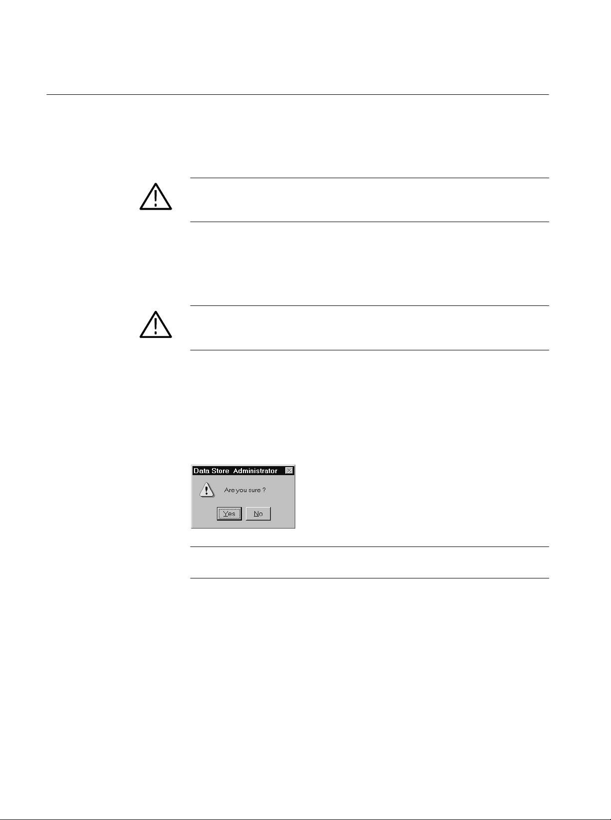
Reference
FAT Delete
Partition Disks
Compress Disks
Refer to Erasing All Files on page 22 for information about using the FAT
Delete command.
CAUTION. The Fat Delete command is irreversible. You cannot recover deleted
files. Never use the Fat Delete command before confirming that important Data
Store files have been backed up on the system disk or on other media.
Refer to Partitioning the Disks on page 19 for information about using the
Partition Disks command.
CAUTION. Partitioning erases all files from the Data Store disks; erased files
cannot be recovered. Be sure to transfer important files to the system disk or
another backup medium before partitioning the Data Store disks.
The Compress Disks command frees the disk space of all files marked for
deletion. This command performs the deletion and then optimizes the files on the
Data Store disks for maximum efficiency. You are given a message box to
confirm this operation.
40
NOTE. The Compress function requires approximately one second per megabyte
of disk space to compress the Data Store disks.
For more information on why compression is necessary, see Special Features of
the Data Store disks beginning on page 14. If you want to remove all files from
the Data Store disks, use the FAT Delete command, described on page 40.
In order to sustain extremely high rates of data transfer, the Single Shot partition
uses a rigid file structure. Unlike a normal computer disk, on which file data can
be fragmented and stored wherever there is free space, the Data Store disks must
store each file as a single data block immediately below the last-acquired file. As
a result, you cannot simply delete an arbitrary file to free up disk space.
MTS 200 Series MPEG Test System Data Store Administrator
Page 57

Reference
The following illustration and paragraphs explain data store file deletion and disk
compression.
File 1
File 2
File 3
File 4
File 5
Empty
(A)
File 1
File 2
File 3
marked
as deleted
File 4
File 5
Empty
Empty Empty
(B) (C)
File 1
File 2
File 4
File 5
Column (A) of the figure represents the data structure after five files have been
acquired. Any new file added to the Data Store disks is written to the top of the
empty section, immediately below file 5.
Column (B) shows what happens when you delete file 3. Because file 3 is
surrounded by other files it is only marked as deleted, but it is not actually
deleted and cannot be overwritten. Thus, the disk space is not free for storing
other files. To free the disk space, you must compress the Data Store disks. You
can undelete it any time before you invoke the Compress command. However,
you can delete the last file listed (File 5 in columns A and B) because it is
adjacent to the empty disk space and you can add directly to that space.
Column (C) shows what happens after a Compress command. File 3 is removed,
files 4 and 5 are moved so that they now follow file 2, and the space freed by
moving files 4 and 5 is added to the empty space. This is the only way to free
disk space after deleting a middle file (other than first deleting all files below it
until the file is the last listed).
NOTE. The Compress function requires approximately one second per megabyte
of disk space to compress the Data Store disks. (For example, 8 Gbyte =
8192 MB; 8192 seconds is 136.5 minutes.)
MTS 200 Series MPEG Test System Data Store Administrator
41
Page 58
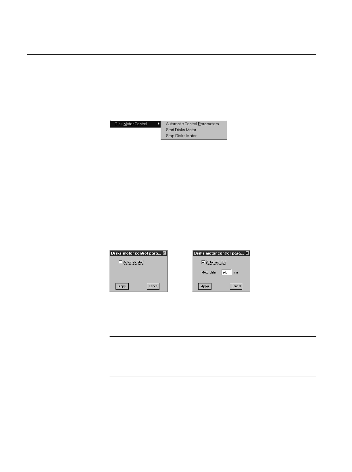
Reference
Disk Motor Control
The Disk Motor Control submenu contains three commands: Automatic Control
Parameters, Start Disks Motor, and Stop Disks Motor. You must log on to
Windows NT as the Administrator to use these commands; refer to Logging On
on page 9 for instructions.
Select Stop Disks Motor to stop the Data Store disk motors when you intend to
leave the test system running for an extended period but know that you will not
be using the Data Store system for some time. Stopping the Data Store disk
motors will extend their life. The motors restart automatically for generation or
acquisition and when you copy a file either to or from the system disk. Restarting the motors takes approximately 20 seconds.
Select Start Disks Motor to manually restart the Data Store disk motors.
Select Automatic Control Parameters to set a motor automatic stop delay.
Select Automatic stop in the resulting dialog box; the Motor delay entry box
appears. Enter the delay time and click Apply to initiate the delay.
42
The disk motors automatically stop after the specified delay period has passed
with no disk access. The default delay is 10 minutes; the recommended
minimum delay period is 240 minutes (four hours).
NOTE. The time required for disk startup can cause unexpected results during
data storage with the MTS 215 Real-Time Analyzer (RTA) application. Do not
stop the disk motors or select Automatic stop if you have an MTS 215 and intend
to capture data through the RTA. Refer to the Real-Time Analyzer User Manual
for information about RTA data storage.
MTS 200 Series MPEG Test System Data Store Administrator
Page 59

The Help Menu
The Help menu has a single command. No online help is available for the Data
Store Administrator.
Select the About command to open the software version information window.
Suppressing the Transfer is Finished Message
In the default configuration, the Data Store Administrator dialog box containing
the message Transfer is finished appears after each acquisition or generation. To
turn off the display of the dialog box after every transfer, change the DefaultAlwaysDialog Box registry parameter. The possible settings for the DefaultAlwaysDialogBox are shown in Table 15.
Reference
T able 15:
Value Description
0x1
0
To change to value of the DefaultAlwaysDialogBox registry parameter, exit the
Data Store Administrator and use the Registry Editor program, Regedt32.exe,
located in the C:\WINNT\system32 directory.
NOTE. You do not have to be logged in with System Administrator rights to
change the DefaultAlwaysDialogBox parameter.
Use the following path to access the DefaultAlwaysDialogBox registry
parameter.
CAUTION. To prevent file corruption, verify that the Data Store Administrator is
not running before editing the DefaultAlwaysDialogBox parameter. When the
Data Store Administrator quits, it writes to the registry file and may overwrite
the value of the DefaultAlwaysDialogBox you have set.
DefaultAlwaysdialogbox registry parameter values
A dialog box is displayed after all transfers (default)
A dialog box is not displayed after transfers
C:\HKEY_CURRENT_USER\SOFTWARE\CARB\CARB0
MTS 200 Series MPEG Test System Data Store Administrator
43
Page 60

Reference
Á
Á
Á
Á
Á
Á
Á
Á
Á
Á
Á
Á
Á
Á
Á
Á
Á
Á
Á
Á
Á
Á
Á
Á
Á
Á
Á
Á
Á
Á
Á
Á
Á
Á
Á
Á
Á
Á
Á
Á
Á
Á
Á
Á
Á
Á
Á
Á
Á
Á
Á
Á
Á
Á
Á
Á
Á
Á
Á
Á
Á
Á
Á
Á
Á
Á
Á
Á
Á
Á
Data Store Transfers
The easiest way to check the operation of an MPEG Test System is with another
MTS 200 Series system. The results of MTS-to-MTS transfers will vary
depending on generation, acquisition, and synchronization mode.
In either acquisition or generation, files can be processed in loop-back mode.
During read or write file loop back, the system must be configured to assure that
the data flow is never interrupted. The file loop back does not cause the insertion
of stuffing data. Refer to Table 16 for information on MTS-to-MTS data
transfers.
T able 16: MTS to MTS transfer results
Generation
Interface
mode
Acquisition mode Expected result
ECL
ББББББ
ББББББ
ECL
ББББББ
ББББББ
ECL
ББББББ
ECL
ББББББ
ББББББ
ББББББ
G.703, TTL, or
ББББББ
10 Mbit/s serial
ББББББ
G.703, TTL, or
10 Mbit/s serial
ББББББ
G.703, TTL, or
ББББББ
10 Mbit/s serial
ББББББ
ББББББ
Nonlooping
ÁÁÁÁ
ÁÁÁÁ
Nonlooping
ÁÁÁÁ
ÁÁÁÁ
Nonlooping
ÁÁÁÁ
Nonlooping
ÁÁÁÁ
ÁÁÁÁ
ÁÁÁÁ
Nonlooping
ÁÁÁÁ
ÁÁÁÁ
Nonlooping
ÁÁÁÁ
Nonlooping
ÁÁÁÁ
ÁÁÁÁ
ÁÁÁÁ
Size:
Á
Sync:
Á
Size:
Á
Sync:
Á
Size:
Á
Sync:
Size:
Á
Sync:
Á
Á
Size:
Á
Sync:
Á
Size:
Á
Sync:
Size:
Á
Sync:
Á
Á
Generator’s File size
ББББББББ
Sync Byte
ББББББББ
Generator’s file size minus three
packets
ББББББББ
Pattern
ББББББББ
Not defined
ББББББББ
None, Pattern, or Sync Byte
> Generator’s file size
ББББББББ
None, Pattern, or Sync Byte
ББББББББ
ББББББББ
Generator’s file size
ББББББББ
Pattern
ББББББББ
Not defined
ББББББББ
Pattern or None
> Generator’s file size
ББББББББ
No synchronization or synchroniza-
ББББББББ
tion on pattern with NO stop after
ББББББББ
desynchronization
Auto stop,
ББББББББ
files are identical
ББББББББ
Auto stop,
first three packets lost
ББББББББ
ББББББББ
No auto stop,
manual stop size is truncated in
ББББББББ
1 Mbyte (1024 Bytes)
No auto stop,
ББББББББ
manual stop size is not predictable
because the algorithm for smooth-
ББББББББ
ing the size of each internal trans-
ББББББББ
ferred block
Auto stop,
ББББББББ
first three packets lost and last
three packets are stuffed “FF”
ББББББББ
No Auto stop,
manual stop is truncated in
ББББББББ
1 Mbyte (1024 Bytes) increments
Auto stop,
ББББББББ
remaining packets to the end of the
file are stuffed “FF”
ББББББББ
ББББББББ
44
MTS 200 Series MPEG Test System Data Store Administrator
Page 61

T able 16: MTS to MTS transfer results (cont.)
Á
Á
Á
Á
Á
Á
Á
Á
Á
Á
Á
Á
Á
Á
Á
Á
Á
Á
Á
Á
Á
Á
Á
Á
Á
Á
Á
Á
Á
Á
Á
Á
Á
Á
Á
Á
Á
Á
Á
Á
Generation
Interface Expected resultAcquisition mode
mode
Reference
G.703, TTL, or
10 Mbit/s serial
БББББББ
БББББББ
БББББББ
БББББББ
Any
БББББББ
БББББББ
Any
БББББББ
БББББББ
Nonlooping
ÁÁÁÁ
ÁÁÁÁ
ÁÁÁÁ
ÁÁÁÁ
Looping
ÁÁÁÁ
ÁÁÁÁ
Looping
ÁÁÁÁ
ÁÁÁÁ
Problems and Troubleshooting
You may encounter problems while using the Data Store Administrator.
H If the Data Store board does not respond to commands, but the application
will respond to mouse or keyboard input, try selecting the Board Reset
command on the Service menu.
H Some problems result in on-screen error messages; refer to Error Messages,
below, for a brief explanation of the Data Store error messages.
Size:
Á
Sync:
Á
Á
Á
Size:
Á
Sync:
Á
Size:
Á
Sync:
Á
> Generator’s file size
ББББББББ
No synchronization and synchro-
ББББББББ
nization on pattern with AUTOMATIC stop after desynchronization
ББББББББ
ББББББББ
Acquisition file size, if defined
ББББББББ
None, Pattern, or Sync Byte (ECL
only)
ББББББББ
Not defined
ББББББББ
None, Pattern, or Sync Byte (ECL
only)
ББББББББ
Auto stop,
the requested size is not reached.
ББББББББ
The size of the stored file is not
ББББББББ
user predictable because of the
ББББББББ
algorithm for smoothing the size of
each internal transferred block
ББББББББ
Auto stop
ББББББББ
ББББББББ
No auto stop,
manual stop size is truncated in
ББББББББ
1 Mbyte (1024 Bytes) increments
ББББББББ
H You may be able to clear an error condition by logging off and shutting down
the test system (power off) for approximately five minutes; try doing so
before proceeding to When All Else Fails, on page 47.
Error Messages
The following is a list of error messages and their meanings. CARB is a French
acronym for the Data Store system.
CARB Time out Error (ERR_CARB_TIME_OUT)
Time–out in TEST mode (such as SCSI access or EISA access).
CARB0 Error (Generation is too fast. Disk <N> too slow)
Reduce the data rate. Refer to Tektronix Service Support for SCSI drive
repair if a problem persists.
Desynchronization (ERR_CARB_DESYNCHRONIZATION)
During an acquisition with stop on desynchronization option, the synchronization pattern has been lost.
MTS 200 Series MPEG Test System Data Store Administrator
45
Page 62

Reference
Disk error (ERR_CARB_DISK_ERROR)
Indicates a disk error on a check condition SCSI request.
Disk Initialization Error (ERR_CARB_DISK_INIT)
The first disk does not respond to the initialization sequence.
End of disk Error (ERR_CARB_END_OF_DISK)
Caused by an attempt to access outside the end of the disk or partition.
End of file Error (ERR_CARB_END_OF_FILE)
Caused by an attempt to access outside the end of the file.
Error busy card (ERR_CARB_DRIVER_BUSY)
There is already a command in progress.
Error : file not found (ERR_CARB_FILE_NOT_FOUND)
The file is not listed on the Data Store disks FAT (file allocation table).
Error : no partition (ERR_CARB_NO_PARTITION)
No partition exists on the Data Store disks; you must create a partition before
capturing or storing a file.
Error : unknown command code (ERR_CARB_CODE_UNKNOWN)
The CPU has received an unknown command.
FA T Error (ERR_CARB_FAT_ERROR)
No partition exists on the Data Store disks; you must create a partition before
capturing or storing a file.
FAT Full Error (ERR_CARB_FAT_FULL)
255 files (32 files, on early instruments) are present on the Data Store disks,
not able to create another one.
File already exist (ERR_CARB_FILE_ALREADY_EXIST)
Try to create a file that already exist.
Line Error (ERR_CARB_LIGNE_ERROR)
Overflow in acquisition mode (the line FIFO is full).
Parameter error (ERR_CARB_PARAM_ERROR)
A parameter of the command is incorrect (such as value out of range).
SCSI Error (ERR_CARB_SCSI_ERROR)
Disk error on non DMA operations.
SCSI Overflow Error (ERR_CARB_OVERFLOW_SCSI)
The SCSI memory bank is full, causing an overflow in acquisition mode.
46
SCSI Read Error (ERR_CARB_READ_SCSI)
Disk error on DMA read operations.
MTS 200 Series MPEG Test System Data Store Administrator
Page 63

Reference
SCSI Write Error (ERR_CARB_WRITE_SCSI)
Disk error on DMA write operations.
System Error (ERR_CARB_SYST_ERROR)
SCSI memory bank underflow or SCSI disks not responding.
Time-out Error (Not detected by CPU) (ERR_CARB_DRIVER_TIME_OUT)
The Data Store board does not respond to the NT driver request (the CPU
board has not received the NT driver request).
(Detected by CPU) (ERR_CARB_DRIVER_TIME_OUT_2)
The Data Store board does not respond to the NT driver request (the CPU
board has received the NT driver request but does not respond to it).
When All Else Fails
If an error message does not explain the problem sufficiently, or if restarting your
system does not clear the problem, contact your nearest Tektronix representative
or service facility.
MTS 200 Series MPEG Test System Data Store Administrator
47
Page 64

Reference
48
MTS 200 Series MPEG Test System Data Store Administrator
Page 65

Appendix A: Data Store I/O Specifications
Á
Á
Á
Á
Á
Á
Á
Á
Á
Á
Á
Á
Á
Á
Á
Á
Á
Á
Á
Á
Á
Á
Á
Á
Á
Á
Á
Á
Á
Á
Á
Á
Á
Á
Á
Á
Á
Á
Á
Á
Á
Á
Á
Á
Á
Á
Á
Á
Á
Á
Á
Á
Á
Á
Á
Á
Á
The tables in this appendix list the electrical characteristics of the MPEG Test
System, Data Store I/O and control ports.
T able 17: G.703 — 8.448 MHz
Characteristic Description Supplemental information
Standards Conformance
Line Encoding
Serial Bit Rate
Generation/Acquisition T est
ББББББББББ
8.448 Mbytes/s ± 10 ppm
Error free
ББББББББ
Input
Voltage Levels
Á
Á
Á
Á
Á
Á
ББББББББ
ББББББББ
ББББББББ
Return Loss (75 W)
ББББББББ
ББББББББ
ББББББББ
ББББББББ
ББББББББ
ББББББББ
ББББББББ
ББББББББ
ББББББББ
Connector
ÁÁББББББББ
ББББББББÁББББББББББББ
Jitter Tolerance
Á
Á
ББББББББ
ББББББББ
ББББББББ
ББББББББ
Output
Pulse Width, nominal
Pulse “Mark” Amplitude
No-Pulse “Space” Voltage
59 ns
2.37 V ± 0.237 V
0 ± 0.237 V
Pulse Shape
Required Receiver Termination
Jitter
Á
Á
Á
Á
Á
MTS 200 Series MPEG Test System Data Store Administrator
ББББББББ
ББББББББ
ББББББББ
ББББББББ
ББББББББ
Resistive, 75 W nominal
ББББББББ
ББББББББ
ББББББББ
ББББББББ
ББББББББ
ITU-CCITT G.703, G.823
HDB3
Tested with a 10 MB file (within the constraints of
ББББББББББББ
synchronization)
Standard level within 0 to 4 dB cable attenuation at
1/2 clock frequency
ББББББББББББ
ББББББББББББ
Standard Levels:
Mark from 2.033 V to 2.607 V
ББББББББББББ
Space from –0.237 to +0.237 V
12 dB, 211 kHz to 422 kHz
ББББББББББББ
18 dB, 422 kHz to 8.448 MHz
ББББББББББББ
14 dB, 8.448 to 12.672 MHz
ББББББББББББ
Male SMB
(shared with the 34.36 Mbit input)
177 ns peak-to-peak 20 Hz to 400 Hz
ББББББББББББ
23.6 ns peak-to-peak 3 kHz to 400 kHz
ББББББББББББ
Log prorated – 400 Hz to 3 kHz
Conforms to 8.448 MHz Pulse Mask, see Figure 3
15 ns peak-to-peak with a 20 Hz lower cut-off and a
ББББББББББББ
400 kHz upper cut-off filter
ББББББББББББ
5 ns peak-to-peak with a 3 kHz lower cut-off and a
ББББББББББББ
400 kHz upper cut-off filter
ББББББББББББ
Allows a cascade of ten different regenerators before
ББББББББББББ
system limit is reached
49
Page 66

Appendix A: Data Store I/O Specifications
Á
Á
Á
Á
Á
Á
Á
Á
Á
T able 17: G.703 — 8.448 MHz (cont.)
Characteristic Supplemental informationDescription
Connector
Return Loss
ББББББББ
ББББББББ
ББББББББ
ББББББББ
ББББББББ
ББББББББ
2.370 V
0.237 V 0.237 V
1.185 V
Male SMB
12 dB – 211 kHz to 422 kHz
ББББББББББББ
18 dB – 422 kHz to 8.448 MHz
ББББББББББББ
14 dB – 8.448 to 12.672 MHz
ББББББББББББ
69 ns
Nominal
pulse
35 ns
50
0 V
0.237 V 0.237 V
0.474 V 0.474 V 0.474 V
49 ns
59 ns
100 ns
118 ns
Figure 3: Pulse specification for a G.703 8.448 MHz pulse
MTS 200 Series MPEG Test System Data Store Administrator
Page 67

Appendix A: Data Store I/O Specifications
Á
Á
Á
Á
Á
Á
Á
Á
Á
Á
Á
Á
Á
Á
Á
Á
Á
Á
Á
Á
Á
Á
Á
Á
Á
Á
Á
Á
Á
Á
Á
Á
Á
Á
Á
Á
Á
Á
Á
Á
Á
Á
Á
Á
Á
Á
Á
Á
Á
Á
Á
Á
Á
Á
Á
Á
Á
Á
Á
Á
Á
Á
Á
Á
Á
Á
Á
Á
T able 18: G.703 — 34.368 MHz
Characteristic Description Supplemental information
Standards Conformance
Connector
Line Encoding
Generation/Acquisition T est
ББББББББББ
Serial Bit Rate
Input
Voltage Levels
Á
Á
Á
Á
ББББББББ
ББББББББ
ББББББББ
ББББББББ
Return Loss (75 W)
Á
Á
ББББББББ
ББББББББ
Connector
ÁÁББББББББ
Jitter Tolerance
Á
Á
ББББББББ
ББББББББ
Output
Pulse Width
Pulse Mark Amplitude
ÁÁББББББББ
No-Pulse Space Voltage
Pulse Shape
Required Receiver Termination
Jitter
Á
Á
Á
Á
Á
Á
Á
ББББББББ
ББББББББ
ББББББББ
ББББББББ
Return Loss
ББББББББ
ББББББББ
ББББББББ
ITU-CCITT G.703, G.823
Male SMB
HDB3
Error free
ББББББББ
Tested with a 10 MB file
ББББББББББББ
(within the constraints of synchronization)
34.368 Mbits/s ± 20 ppm
ББББББББ
ББББББББ
ББББББББ
ББББББББ
Standard level within 0 to 4 dB cable attenuation at
ББББББББББББ
1/2 clock frequency
ББББББББББББ
Standard level:
ББББББББББББ
Mark from 0.9 V to 1.1 V
Space from –0.1 V to +0.1 V
ББББББББББББ
12 dB 860 kHz to 1.72 MHz
ББББББББ
ББББББББ
ББББББББББББ
18 dB 1.72 MHz to 34.368 MHz
ББББББББББББ
14 dB 34.368 to 51.55 MHz
Male SMB
ББББББББÁББББББББББББ
(shared with the 8 Mbit input)
43.7 ns peak-to-peak – 100 Hz to 1 kHz
ББББББББ
ББББББББ
ББББББББББББ
4.37 ns peak-to-peak – 10 kHz to 800 kHz
ББББББББББББ
Log prorated – 1 kHz to 10 kHz
14.5 ns nominal
1.0 V ± 0.1 V
ББББББББ
ББББББББББББ
0 ± 0.1 V
Conforms to 34.368 MHz Pulse Mask (see Figure 4 )
75 W nominal resistive
10 ns peak-to-peak with a 100 Hz lower cut-off and a
ББББББББ
ББББББББ
ББББББББ
ББББББББ
800 kHz upper cut-off filter
ББББББББББББ
2.45 ns peak-to-peak with a 10 kHz lower cut-off and a
ББББББББББББ
800 kHz upper cut-off filter
ББББББББББББ
Allows a cascade of ten different regenerators before
ББББББББББББ
system limit is reached
ББББББББ
ББББББББ
ББББББББ
12 dB – 860 kHz to 1.72 MHz
ББББББББББББ
18 dB – 1.72 MHz to 34.368 MHz
ББББББББББББ
ББББББББББББ
14 dB – 34.368 MHz to 51.55 MHz
MTS 200 Series MPEG Test System Data Store Administrator
51
Page 68

Appendix A: Data Store I/O Specifications
1.0 V
0.5 V
17 ns
Nominal
pulse
0.1 V 0.1 V
8.65 ns
0 V
0.1 V 0.1 V
0.2 V 0.2 V 0.2 V
12.1 ns
14.55 ns
24.5 ns
29.1 ns
Figure 4: Pulse specification for G.703 34.368 MHz
52
MTS 200 Series MPEG Test System Data Store Administrator
Page 69

Appendix A: Data Store I/O Specifications
Á
Á
Á
Á
Á
Á
Á
Á
Á
Á
Á
Á
Á
Á
Á
Á
Á
Á
Á
Á
Á
Á
Á
Á
Á
Á
Á
Á
Á
Á
Á
Á
Á
Á
Á
T able 19: ECL parallel, serial, and control ports
Characteristic Description Supplemental information
Connector
ББББББББББ
ББББББББББ
ББББББББББ
ББББББББББ
ББББББББББ
Generation/Acquisition T est
ББББББББББ
Master/Slave
ББББББББББ
Slave/Master (w/control)
Digital Format
ББББББББ
ББББББББ
ББББББББ
ББББББББ
ББББББББ
ББББББББ
ББББББББ
Parallel Data: Female D25
ББББББББББББ
(pinout described in Table 20 )
ББББББББББББ
Serial Data: Female D25
ББББББББББББ
(pinout described in Table 21)
ББББББББББББ
Flow Control: Female D9
ББББББББББББ
(pinout described in Table 22)
Tested with a 10 MB file at maximum data rates
(within the constraints of synchronization)
ББББББББББББ
ББББББББББББ
Binary , positive logic
Input
Maximum Data Rate
ÁÁББББББББ
ББББББББÁББББББББББББ
Serial: 55 Mbits/s
Parallel: 60 Mbits/s (7.5 MB/s)
Minimum Data Rate Clock Rate: 1 MHz
Serial: 1 Mbits/s
Parallel: 1 Mbits/s (125 KB/s)
Signal Level Amplitude
Time Reference
Differential ECL, Compliant with the ECL 100K levels
Rising edge of the clock
Output
Maximum Data Rate
ÁÁББББББББ
Minimum Data Rate
Á
Á
ББББББББ
ББББББББ
ББББББББÁББББББББББББ
ББББББББ
ББББББББ
Serial: 55 Mbits/s
Parallel: 60 Mbits/s (7.5 MB/s)
Clock rate: 1 MHz
ББББББББББББ
Serial: 1 Mbits/s
ББББББББББББ
Parallel: 1 Mbits/s (125 KB/s)
Clock to Data Timing Data changes within 5 ns of falling clock edge
Signal Level Amplitude
ÁÁББББББББ
ББББББББÁББББББББББББ
Differential ECL,Compliant with the ECL 100K-Series
levels
Required Receiver Termination
110 W, line-to-line
MTS 200 Series MPEG Test System Data Store Administrator
53
Page 70

Appendix A: Data Store I/O Specifications
3
5
5
5
T able 20: ECL parallel data pinout
ECL parallel port Pin Function Pin Function
1
2
4
6
7
8
9
10
11
12
13
Asserted Low differential signal.
1 DCLK 14 DCLK
2 Ground 15 Ground
14
3 DA TA 7 16 DATA 7
1
4 DA TA 6 17 DATA 6
16
17
5 DA TA 5 18 DATA 5
18
6 DA TA 4 19 DATA 4
19
7 DA TA 3 20 DATA 3
20
8 DA TA 2 21 DATA 2
21
21
9 DA TA 1 22 DATA 1
22
23
10 DA TA 0 23 DATA 0
24
11 DV ALID 24 DV ALID
2
12 PSYNC 25 PSYNC
13 Shield
Clock
Data[0 . . 7]
Dvalid
Psync
187 SYNC 1 2 187 SYNC 1 2
Figure 5: Parallel data timing, 188-byte packets
54
MTS 200 Series MPEG Test System Data Store Administrator
Page 71

Packet length = 188 bytes + 16 dummy bytes
Clock
Appendix A: Data Store I/O Specifications
Data[0 . . 7]
Dvalid
Psync
(16) SYNC 1 2 187 SYNC 1 2(1) (16)
Packet length = 204 bytes (Reed-Solomon encoded)
Clock
Data[0 . . 7]
Dvalid
Psync
203 SYNC 1 2 203 SYNC 1 2
Figure 6: Parallel data timing, 204-byte packets
MTS 200 Series MPEG Test System Data Store Administrator
55
Page 72

Appendix A: Data Store I/O Specifications
3
5
5
5
T able 21: ECL serial data pinout
ECL serial port Pin Function
1
2
4
6
7
8
9
10
11
12
13
Asserted Low differential signal.
1 DCLK
2 Ground
14
3 - 9 Not Managed
1
10 DATA 0
16
17
11 DVALID
18
12 PSYNC
19
13 Shield
20
14 DCLK
21
21
15 Ground
22
23
16 – 22 Not Managed
24
23 DATA 0
2
24 DVALID
25 PSYNC
Active edge
data_clock
Data
data_valid
Figure 7: Timing diagram for the ECL serial port
D0
56
MTS 200 Series MPEG Test System Data Store Administrator
Page 73

T able 22: ECL control port pinout
5
ECL control port Pin Function
1 CHCLK (Channel Clock)
2 Ground
1
2
2
3
4
Asserted Low differential signal.
3 CHSYNC (Channel Sync)
6
4 CHCLKEN (Channel Clock Enable)
7
5 Shield
8
6 CHCLK (Channel Clock)
9
7 Ground
8 CHSYNC (Channel Sync)
9 CHCLKEN (Channel Clock Enable)
Appendix A: Data Store I/O Specifications
Active edge
demand_clock
CHCLK
demand_clock_enable
CHCLKEN
Data and stream
data_valid
data_clock
DCLK
Figure 8: ECL Timing diagram with control port
Stuffing bytes
MTS 200 Series MPEG Test System Data Store Administrator
57
Page 74
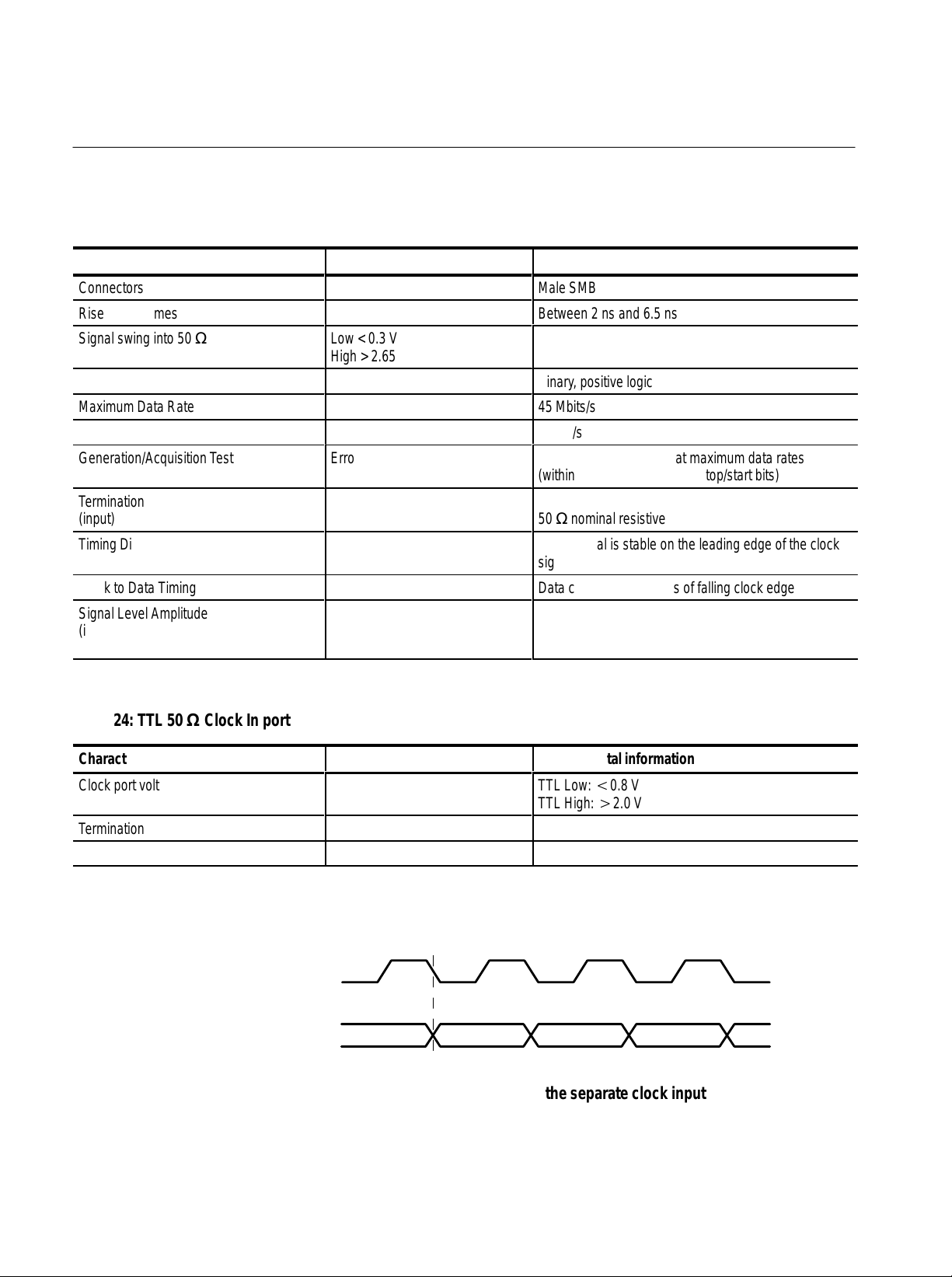
Appendix A: Data Store I/O Specifications
Á
Á
Á
Á
Á
Á
Á
Á
Á
Á
Á
Á
Á
Á
T able 23: 50 W TTL I/O
Characteristic Description Supplemental information
Connectors
Rise & Fall Times
Signal swing into 50 W (output)
БББББББББ
Digital Format
Maximum Data Rate
Low < 0.3 V
ББББББББ
High > 2.65 V
Male SMB
Between 2 ns and 6.5 ns
ББББББББББББ
Binary , positive logic
45 Mbits/s
Minimum Data Rate 1 Mbit/s
Generation/Acquisition T est
БББББББББ
Error free
ББББББББ
Tested with a 10 MB file at maximum data rates
ББББББББББББ
(within the constraints of the stop/start bits)
Termination
БББББББББ
(input)
Timing Diagram
БББББББББ
ББББББББÁББББББББББББ
50 W nominal resistive
DA TA signal is stable on the leading edge of the clock
ББББББББÁББББББББББББ
signal (see Figure 9)
Clock to Data Timing Data changes within 5 ns of falling clock edge
Signal Level Amplitude
(input)
БББББББББ
ББББББББÁББББББББББББ
TTL Low t0.8 V
High u2.0 V
T able 24: TTL 50 W Clock In port
Characteristic Description Supplemental information
Clock port voltage levels
БББББББББ
Termination
Range
ББББББББÁББББББББББББ
Clock
Data
TTL Low: t0.8 V
TTL High: u2.0 V
50 W, nominally resistive
125 kHz to 45 MHz
Figure 9: Timing for the TTL port and the separate clock input
58
MTS 200 Series MPEG Test System Data Store Administrator
Page 75

Appendix A: Data Store I/O Specifications
Á
Á
5
T able 25: 10 Mbit serial port (RS-422 levels I/O Port)
Characteristic Description Supplemental information
Connector
10 Mbit Serial Voltage Levels
9-pin sub-miniature D-type connector (see Table 26)
Differential outputs measured single-ended
Output Low <0.5 V
High >2.5 V
Input Low <–0.5 V differential
High >0.5 V differential
Common Mode Range ±5 Volts
10 Mbit Serial Rise and Fall Times
Maximum Data Rate
Between 2 ns and 12 ns
10 Mbit/s
Minimum Data Rate 1 Mbit/s
Clock to Data Timing Data changes within 10 ns of falling clock edge
Generation/Acquisition T est
ББББББББББ
ББББББББÁББББББББББББ
Tested with a 10 MB file at maximum data rates
(within the constraints of the stop/start bits)
T able 26: 10 Mbit serial port pinout
10 Mbit serial port Pin Function
1 DA TA IN
2 CLK IN
1
2
2
3
4
3 DA TA OUT
6
4 CLK OUT
7
5 Ground
8
6 DA TA IN
9
7 CLK IN
8 DA TA OUT
9 CLK OUT
Asserted Low differential signal.
Clock
Data
Figure 10: Timing diagram for the 10 Mbit Serial port
MTS 200 Series MPEG Test System Data Store Administrator
59
Page 76

Appendix A: Data Store I/O Specifications
T able 27: PLL
Characteristic Description Supplemental information
Range
Resolution
Jitter
Settling Time
Frequency Accuracy
125 kHz to 60 MHz
1 Hz
0.2 UI peak-to-peak over a 1000 UI delay
3 seconds after frequency change
10 ppm ±resolution
60
MTS 200 Series MPEG Test System Data Store Administrator
Page 77

Appendix B: Functional Check
Use the procedure in this section to check Data Store system basic operation.
The procedure checks instrument functionality only; see the optional Service
Manual, Tekronix part number 071-0152-XX (Compaq Proliant platform) or
071-0151-0X (Compaq Prosignia platform), for the complete performance
verification procedure.
Required Equipment
You need the following equipment to perform this check:
H Oscilloscope: capable of measuring 6 V amplitude and 1.4 ns rise time
H 50 W SMB to BNC adapter cable (Tektronix part number 174-3578-XX)
H 75 W SMB to BNC adapter cable (Tektronix part number 174-3579-XX)
H 50 W feed-through terminator (Tektronix part number 011-0049-XX)
H 75 W feed-through terminator (Tektronix part number 011-0103-XX)
The BNC terminators and adapter cables used to connect the test system to the
oscilloscope are standard accessories of the test system.
MTS 200 Series MPEG Test System Data Store Administrator
61
Page 78

Appendix B: Functional Check
Procedure
Perform the following steps to check Data Store system functionality.
1. Connect the equipment as shown in Figure 11.
MTSrear panel
G.703 output
(8.448 Mbits/s)
Test oscilloscope
Ch 1 input
75 W SMB-to-BNC
adapter cable
75 W feed-through
terminator
Figure 11: Initial test system connections for the functional check
2. Switch test system power on.
3. Allow the test system to complete the Windows NT initialization process.
No user intervention is required until initialization is complete.
4. When Windows NT initialization is finished, press
CTRL + ALT + DELETE, as
instructed by the message box.
5. Type MTS100 for Username; do not enter a password. Click OK. If the
default Username or Password have been changed, use the current valid
Username and Password.
62
MTS 200 Series MPEG Test System Data Store Administrator
Page 79

Appendix B: Functional Check
6. Double-click the Data Store Administrator icon in the Tektronix MPEG
Test System program window.
Figure 12: Starting the Data Store Administrator
7. Set up the Data Store Administrator as follows:
a. Click the G (Generate) toolbar button.
b. In the resulting GENERATION dialog box, select any valid Data Store
file as the Source.
c. Select the Loop option.
d. In the dialog box Interface section, make the following selections:
Protocol = Master.
Port = G703
Output clock = 8.448 Mbits.
e. Click Start.
8. Trigger the oscilloscope.
9. Check for a frequency of approximately 4.224 MHz, amplitude of approxi-
mately 5 volts, and rise time of approximately 4 ns. See Figure 13 for the
location of the measurement points on the waveform.
10. Move the output cable to the G703, 34 M output. See Figure 13.
MTS 200 Series MPEG Test System Data Store Administrator
63
Page 80

Appendix B: Functional Check
MTS rear panel
G.703 output
(34.368 Mbits/s)
T
R
10-90%
Ch 1 input
75 W SMB-to-BNC
adapter cable
Frequency
Test oscilloscope
Figure 13: Setup for measuring the G.703 34.368 Mbit/s output
Amplitude
75 W feed-through
terminator
11. Set up the Data Store Administrator as follows:
a. Click the Stop (red hand) toolbar button.
b. Click the G (Generate) toolbar button.
c. In the resulting GENERATION dialog box, select any valid Data Store
file as the Source.
d. Select the Loop option.
e. In the Interface section of the dialog box, make the following selections:
Protocol = Master.
Port = G703
Output clock = 34.368 Mbits
f. Click Start.
12. Trigger the oscilloscope.
13. Check for a frequency of approximately 17.2 MHz, peak-to-peak amplitude
of approximately 2.3 volts, and a rise time of approximately 3.8 ns. See
Figure 13.
64
MTS 200 Series MPEG Test System Data Store Administrator
Page 81

Appendix B: Functional Check
14. Remove the 75 W SMB-to-BNC adapter cable from the oscilloscope and the
MTS 200 Series G703 34 M Out connector.
15. Connect a 50 W SMB-to-BNC adapter cable from the TTL 50 W Clock I/O
Port, through a 50 W feed-through terminator, to the oscilloscope input. See
Figure 14.
MTS rear panel
Clock I/O TTL
50 W serial port
T
R
10-90%
Ch 1 input
50 W SMB-to-BNC
adapter cable
Frequency
Test oscilloscope
Figure 14: Setup for measuring the TTL 50 ohm clock I/O port
Amplitude
50 W feed-through
terminator
16. Set up the Test System as follows:
a. Click the Stop (red hand) toolbar button.
b. Click the G (Generate) toolbar button.
c. In the resulting GENERATION dialog box, select any valid Data Store
file as the Source.
d. Select the Loop option.
e. In the Interface section of the dialog box, make the following selections:
Protocol = Master.
Port = TTL
Output clock = PLL
Frequency = 1,000,000 Bits/s
MTS 200 Series MPEG Test System Data Store Administrator
65
Page 82

Appendix B: Functional Check
f. Click Start.
17. Trigger the oscilloscope.
18. Check for a frequency of approximately 1 MHz, amplitude of approximately
3.0 volts and a rise time of approximately 2.0 ns. See Figure 14.
19. Move the Test System output cable to the TTL 50 W Data I/O Port. See
Figure 15.
MTS rear panel
Data I/O TTL
50 W serial port
T
R
10-90%
Ch 1 input
50 W SMB-to-BNC
adapter cable
Data rate
Test oscilloscope
Figure 15: Setup for measuring the TTL 50 ohm data I/O port
Amplitude
50 W feed-through
terminator
66
MTS 200 Series MPEG Test System Data Store Administrator
Page 83

Appendix B: Functional Check
20. Set up the Test System as follows:
a. Click the Stop (red hand) toolbar button.
b. Click the G (Generate) toolbar button.
c. In the resulting GENERATION dialog box, select any valid Data Store
file as the Source.
d. Select the Loop option.
e. In the Interface section of the dialog box, make the following selections:
Protocol = Master.
Port = TTL
Output clock = PLL
Frequency = 45,000,000 Bits/s
f. Click Start.
21. Trigger the oscilloscope on the plus slope.
22. Check for an amplitude of approximately 3.0 volts, a data rate of 45 MHz
and a rise time of approximately 2.0 ns. See Figure 15.
23. Move the Test System output cable to the TTL 50 W Clock I/O Port. See
Figure 14.
24. Trigger the oscilloscope.
25. Check for an amplitude of approximately 3.0 volts, frequency of 45 MHz
and a rise time of approximately 2.0 ns. See Figure 14.
26. In the Data Store Administrator, click the Stop (red hand) toolbar button.
This completes the functional check.
MTS 200 Series MPEG Test System Data Store Administrator
67
Page 84

Appendix B: Functional Check
68
MTS 200 Series MPEG Test System Data Store Administrator
Page 85

Index
Numbers
10 Mbit serial port, 6
specifications, 59
50 Ohm TTL Port, 7
Specifications, 58
A
Acq/Gen menu
Data Store Administrator, 31
Disk Manager, 31
Acquisition, Data Store system, 15
Adapters, 8
B
Board Reset, 39
Board to PC (Read), 28
Burst mode, Transport Stream Generation, 38
C
Cables, 7
CARB, definition, 13
Change password, 10
Check function, 61
Clock Input, 6
Clock Port, Specifications, 58
Compress Disks, 40
Control Port, File Acquisition, 35
Control Signals, Transport Stream Generation, 38
Copying files
from Data Store disks to system disk, 28
from system to Data Store disks, 28
D
Deleted, files marked as, 28
Deleting, last file in FAT Table, 30
Deleting files, Data Store Administrator, 29
DEN, Transport Stream Generation, 38
Dialog Interrupt, Resource Parameter, 39
Disk, system, 13
Disk, Data Store, 13
motor control, 42
partitioning, 19
DMA Channel, Resource Parameter, 39
DMA Interrupt, Resource Parameter, 39
E
ECL Control port, 5
ECL Parallel/Serial port, 2
Specifications, 53
Error messages, 45
Exit, 11
F
FAT delete, 40
FAT Read, 27
File menu, Data Store Administrator, 27
File size
acquisition, 32
limitations, 21
File system, access data store files, 18
File transfer, MTS-to-MTS, 44
Free disk space, Data Store disks, 41
Freeing disk space, Data Store Disks, 40
Frequency Range
Data Store ports, 33
Transport Stream Generation, 37
Frequency Step Size, PLL, 33
Functional check, 61
Data Store acquisition, 15
Data Store Administrator, 13
Data Store disks
access file system, 18
defined, 13
motor control, 42
special features, 14
use, 14
Data Store generation, 17
MTS 200 Series MPEG Test System Data Store Administrator
G
G.703 data rates, 33
G.703 port, 5
G.703 Specifications
34.368 MHz, 51
8.448 MHz, 49
Generation, 35–36
Data Store system, 17
69
Page 86

Index
I
I/O, 2
Inputs and outputs, 2
Internal Clock, File Acquisition, 33
Interrupt, File Acquisition, 32
Interrupt Transfer, 38
L
Loggin on, 9
Login, 9
Loop, Transport Stream Generation, 36
Loop partition, 14
Loss of Synchronization, Acquisition, 34
M
Master
acquisition protocol, 32
generation protocol, 37
MSB first, 33
O
Output Clock, Transport Stream Generation, 37
P
Partition Data Store disks, 19
Password, 10
changing, emergency repair disk, 10
Pattern synchronization, file acquisition, 33
PC to Board (Write), 28
PLL
File Acquisition, 33
Specifications, 60
Transport Stream Generation, 37
Port
File Acquisition, 33
Transport Stream Generation, 37
Port Parameters, Transport Stream Generation, 37
Ports, input and output, 2
Power switch, 9
Protection, software key, 8
Protocol
File Acquisition, 32
Transport Stream Generation, 37
PSYNC, File Acquisition, 33
PSYNC Mode, Acquisition, Synchronization, 34
R
Registry , editing values, 43
Resource Parameters, 39
S
SB signal, generation, 38
Service menu, Data Store Administrator, 38–39
Shut down, 11
Single shot partition, 14
Size
File Acquisition, 32
Transport Stream Generation, 36
Slave
acquisition protocol, 32
generation protocol, 37
Slot, Resource Parameter, 39
Software description, Data Store Administrator, 1
Software protection key, connecting to parallel port, 8
Software version, xi
Specifications, 49
Stop if Desynchronized, File Acquisition, 34
Stuffing Bytes
File Acquisition, 35
Transport Stream Generation, 38
Sync Signal Size, Transport Stream Generation, 38
Synchro Byte Size, File Acquisition, 35
Synchronization, file acquisition, 33
System Disk, definition, 13
System disk, 13
file size limitations, 21
T
T est, function, 61
T oolbar, Data Store Administrator, 26
Troubleshooting, 45
TTL 50 Ohm Serial Port, 7
U
Undelete, 30
Useful Bytes
File Acquisition, 34
Transport Stream Generation, 38
V
Version, software, xi
W
Windows NT, initialization, 9
70
MTS 200 Series MPEG Test System Data Store Administrator
Page 87

Index
MTS 200 Series MPEG Test System Data Store Administrator
71
Page 88

Index
72
MTS 200 Series MPEG Test System Data Store Administrator
 Loading...