

Page 1

xx
MTM4UP Upgrades
MTM400 and MTM400A
ZZZ
DTV Monitors
Instructions
*P075097302*
075-0973-02
Page 2

Page 3

xx
MTM4UP Upgrades
MTM400 and MTM400A
ZZZ
DTV Monitors
Instructions
Warning
The servicing instructions are for use by qualified personnel
only. To avoid personal injury, do not perform any servicing
unless you are qualified to do so. Refer to all safety summaries
prior to performing service.
www.tektronix.com
075-0973-02
Page 4

Copyright © Tektronix. All rights reserved. Licensed software products are owned by Tektronix or its subsidiaries
or suppliers, and are protected by national copyright laws and international treaty provisions.
Tektronix products are covered by U.S. and foreign patents, issued and pending. Information in this publication
supersedes that in all previously published material. Specifications and price change privileges reserved.
TEKTRONIX and TEK are registered trademarks of Tektronix, Inc.
FlexVuPlus is a registered trademark of Tektronix, Inc.
Contacting Tektronix
Tektronix, Inc.
14200 SW Karl Braun Drive
P.O . Bo x 50 0
Beaverton, OR 97077
USA
For product information, sales, service, and technical support:
In North America, call 1-800-833-9200.
World wide, vi sit www.tektronix.com to find contacts in your area.
Page 5

Table of Contents
General Safety Summary .......................................................................................... ii
Service Safety Summary................................ .................................. ........................ iv
Kit Description............................. ................................ ................................ ......... 1
Minimum Too
Kit Parts Lists ........................... ................................ ................................ ....... 6
Application Firmware Upgrade ................................ ................................ .................. 13
Firmware Upgrade (RUI v2.6.1 and Below)............................................................... 15
Firmware Upgrade (RUI v3.0 and Above)......................... ................................ ........ 31
Command Line Firmware Upgrade....................... .................................. ................ 38
Softwar
Hardware Option Upgrade.......................................... ................................ .............. 57
We
e Option Upgrade......................................................................................... 41
Option Keys ... .................................. ................................ .............................. 41
RUI Versions .................................................................................................. 41
Software Option Upgrade (RUI v2.6.1 and Below)..................... .................................. 43
Software Option Upgrade (RUI v3.0 and Above)................................. ........................ 48
Troubleshooting....................... ................................ ................................ ........ 52
fying the Software Option Upgrade...................... ................................ .............. 52
Ver i
Preparation............. .................................. ................................ ...................... 58
Install the New Interface Card............................................................................... 58
Install the SFP Module (GbE interface Only) . ................................ ............................ 71
Verify the Hardware Upgrade ............................................................................... 72
bMSM Software Upgrade......... ................................ ................................ ............ 79
Upgrading the WebMSM Software ......................................................................... 79
Technical Support............................................................................................. 79
l and Equipment List ......................................................................... 3
MTM4UP Upgrade Instructions i
Page 6

General Safety Summary
General Safet
To Avoid Fi
re or Personal
Injury
ySummary
Review the fo
this product or any products connected to it.
To avoid pot
Only qualified personnel should perform service procedures.
Use Proper Power Cord. Use only the power cord specified for this product and
certified for the country of use.
Ground the Product. This product is grounded through the grounding conductor
of the power cord. To avoid electric shock, the grounding conductor must be
connected to earth ground. Before making connections to the input or output
terminals of the product, ensure that the product is properly grounded.
Observe All Terminal Ratings. To avoid fire or shock hazard, observe all ratings
and markings on the product. Consult the product manual for further ratings
information before making connections to the product.
The inputs are not rated for connection to mains or Category II, III, or IV circuits.
Power Disconnect. The power cord disconnects the product from the power source.
Donotblockthepowercord;itmustremain accessible to the user at all times.
llowing safety precautions to avoid injury and prevent damage to
ential hazards, use this product only as specified.
Do Not Operate Without Covers. Do not operate this product with covers or panels
removed.
Do Not Operate With Suspected Failures. If you suspect that there is damage to this
product, have it inspected by qualified service personnel.
Avoid Exposed Circuitry. Do not touch exposed connections and components
when power is present.
Use Proper Fuse. Useonlythefusetypeandratingspecified for this product.
Wear Eye Prote ction. Wear eye protection if exposure to high-intensity rays or
laser radiation exists.
Do Not Operate in Wet/Damp Conditions.
Do Not Operate in an Explosive Atmosphere.
Keep Product Surfaces Clean and Dry.
Provide Proper Ventilation. Refer to the manual’s installation instructions for
details on installing the product so it has proper ventilation.
ii MTM4UP Upgrade Instructions
Page 7

General Safety Summary
Terms in this Manual
Symbols and Terms on the
Product
These terms may
WAR N ING. Warning statements identify conditions or practices that could result
in injury or loss of life.
CAUTION. Caution statements identify conditions or practices that could result in
damage to this product or other p roperty.
These terms may appear on the product:
DANGER in
the marking.
WAR NI N G
read the marking.
CAUTIO
The following symbol(s) may appear on the product:
appear in this manual:
dicates an injury hazard immediately accessible as you read
indicates an injury hazard not immediately accessible as you
N indicates a hazard to property including the product.
MTM4UP Upgrade Instructions iii
Page 8

Service Safety Summary
Service Safet
y Summary
Only qualifie
Safety Summary and the General Safety Summary before performing any service
procedures.
Do Not Service Alone. Do not perform internal service or adjustments of this
product unless another person c apable of rendering first aid and resuscitation is
present.
Disconnect Power. To avoid electric shock, switch off the instrument power, then
disconnect the power cord from the mains power.
Use Care When Servicing With Power On. Dangerous voltages or currents may
exist in
disconnect test leads before removing protective panels, soldering, or replacing
components.
To avoid electric shock, do not touch exposed connections.
d personnel should perform service procedures. Read this Service
this product. Disconnect power, remove battery (if applicable), and
iv MTM4UP Upgrade Instructions
Page 9

Kit Description
This document provides instructions for installing MTM4UP software and
hardware upgrades into an existing MTM400 or MTM400A MPEG Transport
Stream Monitor. All MTM4UP upgrade kits include an application firmware
CD-ROM that enables you to update your monitor with the latest version of the
RUI (Remote
The following table lists the MTM4UP upgrades that are supported by this
document.
Table 1: Supported software and hardware upgrades
Product Option Description
MTM4UP
01
02
03
04
05
06
07
CF Hardware upgrade to add a COFDM interface card
EP
S2 Hardware upgrade to add a DVB-S2 interface
GE Hardware upgrade to add a IP Video G igabit Ethernet (GbE ) interface card
LX
QA Hardware upgrade to add a QAM (Annex A) interface card
QB2 Hardware upgrade to add a QAM (Annex B, Level 1 and 2) interface card
QC Hardware upgrade to add a QAM (Annex C) interface card
SX Hardware upgrade to add a 850nm SFP, optical gigabit Ethernet port to the GbE interface
VS Hardware upgrade to add a 8VSB interface card
ZX
Software upgrade to add recording capability
Software upgrade to add transport stream Service Information analysis (PSI/SI/PSIP/ARIB structure
view and repetition graphs)
Software upgrade to add template testing with template scheduling (for u ser-defined service plan testing)
Software upgrade to add PCR analysis with graphical results views
Software upgrade to add bit-rate testing including PID groups and PID variability
Software upgrade to add service logging
Software upgrade to add automatic channel changing for polling multiple streams
Hardware upgrade to add a 8PSK/QPSK interface card
Hardware upgrade to add a 1310nm SFP, optical gigabit Ethernet port to the GbE interface
Hardware upgrade to add a 1550nm SFP, optical gigabit Ethernet port to the GbE interface
User Interface).
The upgrade process contains these main steps:
Upgrade the application firmware version (all MTM4UP options)
Apply the new option key (MTM4UP options 01, 02, 03, 04, 05, 06, 07, and
QC only)
Install the new interface card (MTM4UP options CF, EP, S2, GE, QA, QB2,
QC, and VS only)
MTM4UP Upgrade Instructions 1
Page 10

Kit Description
Supported Products
Install the opt
ical gigabit Ethernet/Fibre Channel port on the GbE interface
(MTM4UP options LX, SX, and ZX only)
Reinstall the
We bMSM software (all MTM4UP options; only if you upgraded
the application firmware and use the WebMSM software)
The following products are supported by this upgrade kit (except as noted under
MTM400 Moni
tor Serial Number Versions below):
MTM400 MPEG Transport Stream Monitor
MTM400A MPEG Transport Stream Monitor
MTM400A DTV Monitor
NOTE. A fully licensed version of the WebMSM Monitoring System Manager is
available to users of MTM400 or MTM400A monitors with RUI v3.0 or above
ed. The WebMSM software enables you to monitor transport streams on
install
multiple MTM400 and MTM400A monitors from a single PC.
The Web
MSM s oftware package for RUI v3.0 and above is available on the
Tektronix Web site (www.tektronix.com/software) and on the application firmware
CD-ROM that was supplied with this upgrade kit.
MTM400 Monitor Serial
Number Formats
Two versions of the MTM400 monitor have been produced with different serial
number formats as shown below. These upgrade instructions do not apply to
MTM400 monitors that have the GB* serial number format. If your monitor
has a GB* serial number, you will be advised of the correct upgrade procedure
when you order an upgrade. The serial number of each monitor is printed on a
bel attached to the rear panel.
la
Serial number formats
GB400–xxxx (Example: GB400-1234)
Bxxxxxx (Example: B010100)
2 MTM4UP Upgrade Instructions
Page 11

Minimum Tool and Equipment List
This section lists the tools and equipment required to perform the MTM4UP
upgrades described in this document.
Kit Description
Firmware and Software
Option Upgrades
To perform a firmware or a software option upgrade, you must use a PC to access
the RUI (Remote User Interface) on the MTM400 or MTM400A monitor. The PC
and the monitor must be connected to the same Ethernet network.
The system requirements of the PC depend on which version of the RUI is
installed on your monitor. MTM400 monitors were shipped from the factory with
RUI version 2.6.1 or below. MTM400A monitors are shipped with RUI version
3.0 or above.
The MTM400 and MTM400A monitors can operate using either version of the
RUI. You will be able to determine if the factory–issued RUI version has been
changed
on your monitor when you attempt to log in:
If your monitor has RUI v2.6.1 or below installed, the login screen will
appear
as follows:
MTM4UP Upgrade Instructions 3
Page 12

Kit Description
If your monitor
has RUI v3.0 or above installed, the login screen will appear
as follows:
The foll
owing tables list the system requirements for monitors operating with RUI
v2.6.1 or below and RUI v3.0 or above.
Table 2: PC system requirements for RUI v2.6.1 or below
Characteristic
Minimum specification 1 GHz Intel Pentium Processor (Preferred: 2 GHz)
Operating system Microsoft Windows 2000 or Windows XP
Disk space
Ethernet
talled software
Ins
RAM
CD-ROM drive
Display 1024 x 768 pixel video monitor with 16 available c olors
Description
ommended: Windows XP Pro)
(Rec
ree disk space
2GBf
100-base T
10/
rosoft Internet Explorer, Version 6.0 minimum;
Mic
Microsoft Java Virtual Machine installed, Version
5.0 minimum
1GB
8x
4 MTM4UP Upgrade Instructions
Page 13

Kit Description
Signal Interface Hardware
Upgrades
Table 3: PC syst
Characteristic
Minimum specification 1.2 GHz Intel Pentium Processor (Preferred: 2 GHz)
Operating system Microsoft Windows 2000, Windows XP, and Windows
Disk space
Ethernet
Installed software Microsoft Internet Explorer, Version 7.0 m inimum;
RAM
CD–ROM drive
Display
em requirements for RUI v3.0 or above
Description
Vista (Recommended: Windows XP Pro)
2GBfreediskspace
10/100–base T
SunJavaRu
07 minimum (1.6.0_10 or later)
1GB
8x
1024 x 768 pixel v ideo monitor with 16 bit (65000)
available colors
ntime Environment Version 6 Update
You will need the equipment listed below to physically install the signal interface
hardware upgrades.
Required tools and equipment Part number
Anti-static wrist strap NA
A screwdriver with T-10, T-15, and T-20
TORX tips
NA
erify that the installed interface card is operating properly, you will need a PC
To v
meeting the minimum requirements and a suitable transport stream input for the
interface type that you received with this upgrade kit. (See Table 2 on page 4.)
(See Table 3 on page 5.)
MTM4UP Upgrade Instructions 5
Page 14

Kit Description
Kit Parts Lists
The following tables list the parts supplied with each of the upgrade kits.
Table 4: MTM4UP 01, 02, 03, 04, 05, 06, and 07 parts list (software options)
Quantity
1EA NA
1EA NA
1 EA 063-4135-xx MTM400A, IPM400A, and RFM300 Product Documentation
1 EA 063-4136-xx MTM400A, IPM400A, and RFM300 Application Firmware
1 EA 071-2492-xx
1 EA 075-0973-02 MTM4UP Upgrades Instructions
Table 5
Quantity
1EA NA
1EA 015-0
1EA 063-
1EA 063-
1EA 071
1EA 071
1 EA 075-0973-02 MTM4UP Upgrades Instructions
1 EA 174-4782-xx Power cable; 8 conductor, 15.9 L
EA
1
1 EA 174-5135-xx
8 EA 211-0722-xx
1 EA 672-1789-xx
Part number Description
Option key document for a specified MTM400 or MTM400A
monitor
Product Upgrade identification sticker
CD–ROM
CD–ROM
MTM400A Quick Start User Manual (English)
(071-2632-xx)
(071-2493-xx)
(German)
(Japanese)
: MTM4UP CF parts list (COFDM interface)
mber
Part nu
688-xx
4135-xx
4136-xx
-2191-xx
-2492-xx
(071-2632-xx)
(071-2493-xx)
74-5063-xx
1
ption
Descri
Product Upgrade identification sticker
Adapter, RF; BNC Jack to F Plug
00A, IPM400A, and RFM300 Product Documentation
MTM4
CD-ROM
00A, IPM400A, and RFM300 Application Firmware
MTM4
CD-ROM
China RoHS Supplemental Information Sheet
MTM400A Quick Start User Manual (English)
(German)
apanese)
(J
Serial cable; 1x5, 8.00 inches, Baseband to Processor
RF cable; BNC to BNC, 75 Ohm
Machine screw; 6-32 x 0.250, PNH, T-15 TORX
COFDM and Baseband circuit board assembly; tested set
6 MTM4UP Upgrade Instructions
Page 15

Kit Description
Table 6: MTM4UP
Quantity
1EA NA
1 EA 063-4135-xx MTM400A, IPM
1 EA 063-4136-x
1 EA 071-2191-x
1 EA 071-2492-
1 EA 075-0973-02 MTM4UP Upgrades Instructions
1 EA 174-4782-xx Power cable; 8 conductor, 15.9 L
1 EA 174-506
1 EA 174-513
8EA 211-07
1 EA 672-17
EP parts list (8PSK / QPSK interface)
Part number Description
Product Upgrade identification sticker
CD-ROM
x
x
xx
(071-2632-xx)
(071-2493-xx)
3-xx
5-xx
22-xx
90-xx
MTM400A, IP
CD-ROM
China RoHS Supplemental Information Sheet
MTM400A Quick Start User Manual (English)
(German)
(Japanes
Serial cable; 1x5, 8.00 inches, Baseband to Processor
RF cable; BNC to BNC, 75 Ohm
Machine screw; 6-32 x 0.250, PNH, T-15 TORX
8PSK / QPSK and Baseband circuit board assembly; tested
set
M400A, and RFM300 Application Firmware
e)
400A, and RFM300 Product Documentation
Table 7: MTM4UP S2 parts list (DVB-S2 interface)
Quantity
1EA NA
1 EA 063-4135-xx MTM400A, IPM400A, and RFM300 Product Documentation
1 EA 063-4136-xx MTM400A, IPM400A, and RFM300 Application Firmware
1 EA 071-2191-xx
1 EA 071-2492-xx
1 EA 075-0973-02 MTM4UP Upgrades Instructions
1 EA 174-4782-xx Power cable; 8 conductor, 15.9 L
1 EA 174-5063-xx
1 EA 174-5135-xx
8 EA 211-0722-xx
1 EA 672-1790-xx
Part number Description
Product Upgrade identification sticker
CD-ROM
CD-ROM
China RoHS Supplemental Information Sheet
MTM400A Quick Start User Manual (English)
(071-2632-xx)
(071-2493-xx)
(German)
(Japanese)
Serial cable; 1x5, 8.00 inches, Baseband to Processor
RF cable; BNC to BNC, 75 Ohm
Machine screw; 6-32 x 0.250, PNH, T-15 TORX
DVB-S2 and Baseband circuit board assembly; tested set
MTM4UP Upgrade Instructions 7
Page 16

Kit Description
Table 8: MTM4UP
Quantity
1EA NA
1 EA 063-4135-xx MTM400A, IPM
1 EA 063-4136-x
1 EA 071-2191-x
1 EA 071-2492-
1 EA 075-0973-02 MTM4UP Upgrades Instructions
1 EA 174-4782-xx Power cable; 8 conductor, 15.9 L
1 EA 174-506
1 EA 174-528
9 EA 211 -07
1EA 671-62
GE parts list (IP Video Gigabit Ethernet interface)
Part number Description
Product Upgrade identification sticker
400A, and RFM300 Product Documentation
CD-ROM
x
x
xx
(071-2632-xx)
(071-2493-xx)
3-xx
7-xx
22-xx
00-xx
MTM400A, IP
CD-ROM
China RoHS Supplemental Information Sheet
MTM400A Quick Start User Manual (English)
(German)
(Japanes
Serial cable; 1x5, 8.00 inches, Baseband to Processor
RF cable; BNC to BNC, 75 Ohm
Machine screw; 6-32 x 0.250, PNH, T-15 TORX
GbE circuit board assembly, ASI/SDI; tested
M400A, and RFM300 Application Firmware
e)
Table 9: MTM4UP LX parts list (1310nm SFP optical port for GbE interface)
Quantity
1EA NA
1 EA 063-4135-xx MTM400A, IPM400A, and RFM300 Product Documentation
1 EA 063-4136-xx MTM400A, IPM400A, and RFM300 Application Firmware
1 EA 131-7957-xx
1 EA 071-2191-xx
1 EA 071-2492-xx
1 EA 075-0973-02 MTM4UP Upgrades Instructions
Part number Description
Product Upgrade identification sticker
CD-ROM
CD-ROM
1310nm SFP optical gigabit Ethernet/Fibre Channel port
China RoHS Supplemental Information Sheet
MTM400A Quick Start User Manual (English)
(071-2632-xx)
(071-2493-xx)
(German)
(Japanese)
8 MTM4UP Upgrade Instructions
Page 17

Kit Description
Table 10: MTM4U
Quantity
1EA NA
1 EA 063-4135-xx MTM400A, IPM
1 EA 063-4136-x
1 EA 131-7834-x
1 EA 071-2191-
1 EA 071-2492-
1 EA 075-0973-02 MTM4UP Upgrades Instructions
P SX parts list (850nm SFP optical port for GbE interface)
Part number Description
Product Upgrade identification sticker
400A, and RFM300 Product Documentation
CD-ROM
x
x
xx
xx
(071-2632-xx)
(071-2493-xx)
MTM400A, IP
CD-ROM
850nm SFP optical gigabit Ethernet/Fibre Channel port
China RoHS Supplemental Information Sheet
MTM400A Quick Start User Manual (English)
(German)
(Japanes
M400A, and RFM300 Application Firmware
e)
Table 11: MTM4UP ZX parts list (1550nm SFP optical port for GbE interface)
Quantity
1EA NA
1 EA 063-4135-xx
1 EA 063-4136-xx
1 EA 131-7958-xx
1 EA 071-2191-xx
1 EA 071-2492-xx
1 EA 075-0973-02 MTM4UP Upgrades Instructions
Part number Description
Product Upgrade identification sticker
MTM400A Product Documentation CD-ROM
MTM400A Application Firmware CD-ROM
1550nm SFP optical gigabit Ethernet/Fibre Channel port
China RoHS Supplemental Information Sheet
MTM400A Quick Start User Manual (English)
(071-2632-xx)
(071-2493-xx)
(German)
(Japanese)
Table 12: MTM4UP QA parts list (QAM Annex A interface)
Quantity
1EA NA
1 EA 063-4135-xx
1 EA 063-4136-xx
1 EA 071-2191-xx
1 EA 071-2492-xx
1 EA 075-0973-02 MTM4UP Upgrades Instructions
1 EA 174-4782-xx Power cable; 8 conductor, 15.9 L
2 EA 174-4850-xx
7 EA 211-0722-xx
1 EA 671-5608-xx
Part number Description
Product Upgrade identification sticker
MTM400A Product Documentation CD-ROM
MTM400A Application Firmware CD-ROM
China RoHS Supplemental Information Sheet
MTM400A Quick Start User Manual (English)
(071-2632-xx)
(071-2493-xx)
(German)
(Japanese)
RF cable; coaxial, RFD, 50 Ohm, 16.00 inches
Machine screw; 6-32 x 0.250, PNH, T-15 TORX
QAM (Annex A) circuit board assembly; tested
MTM4UP Upgrade Instructions 9
Page 18

Kit Description
Table 13: MTM4U
Quantity
1EA NA
1 EA 063-4135-xx
1 EA 063-4136-x
1 EA 071-2191-x
1 EA 071-2492-
1 EA 075-0973-02 MTM4UP Upgrades Instructions
1 EA 174-4782-xx Power cable; 8 conductor, 15.9 L
1 EA 174-506
1 EA 174-513
8 EA 211 -07
1EA 672-17
P QB2 parts list (QAM Annex B interface)
Part number Description
Product Upgrade identification sticker
MTM400A Product Documentation CD-ROM
x
x
xx
(071-2632-xx)
(071-2493-xx)
3-xx
5-xx
22-xx
91-xx
MTM400A Application Firmware CD-ROM
China RoHS Supplemental Information Sheet
MTM400A Quick Start User Manual (English)
(German)
(Japanese
Serial cable; 1x5, 8.00 inches, Baseband to Processor
RF cable; BNC to BNC, 75 Ohm
Machine screw; 6-32 x 0.250, PNH, T-15 TORX
QAM (Annex B2) and Baseband circuit board assembly;
tested set
)
Table 14: MTM4UP QC parts list (QAM Annex C interface)
Quantity
1EA NA
1EA NA
1 EA 063-4135-xx
1 EA 063-4136-xx
1 EA 071-2191-xx
1 EA 071-2492-xx
1 EA 075-0973-02 MTM4UP Upgrades Instructions
1 EA 174-4782-xx Power cable; 8 conductor, 15.9 L
2 EA 174-4850-xx
7 EA 211-0722-xx
1 EA 671-5625-xx
Part number Description
Option key document for a specified MTM400 or MTM400A
monitor
Product Upgrade identification sticker
MTM400A Product Documentation CD-ROM
MTM400A Application Firmware CD-ROM
China RoHS Supplemental Information Sheet
MTM400A English Quick Start User Manual
(071-2632-xx)
(071-2493-xx)
(German)
(Japanese)
RF cable; coaxial, RFD, 50 Ohm, 16.00 inches
Machine screw; 6-32 x 0.250, PNH, T-15 TORX
QAM (Annex C) circuit board assembly; tested
10 MTM4UP Upgrade Instructions
Page 19

Kit Description
Table 15: MTM4U
Quantity
1EA NA
1 EA 015-0688-xx
1 EA 063-4135-x
1 EA 063-4136-x
1 EA 071-2191-
1 EA 071-2492-
1 EA 075-0973-02 MTM4UP Upgrades Instructions
1 EA 174-4782-xx Power cable; 8 conductor, 15.9 L
1 EA 174-506
1 EA 174-51
8EA 211-07
1 EA 672-1
P VS parts list (8VSB interface)
Part number Description
Product Upgrade identification sticker
ADAPTER, RF; BNC JACK TO F PLUG
x
x
xx
xx
(071-2632-xx)
(071-2493-xx)
3-xx
35-xx
22-xx
792-xx
MTM400A Product Documentation CD-ROM
MTM400A Application Firmware CD-ROM
China RoHS Supplemental Information Sheet
MTM400A English Quick Start User Manual
(German)
(Japanes
Serial cable; 1x5, 8.00 inches, Baseband to Processor
RF cable; BNC to BNC, 75 Ohm
Machine screw; 6-32 x 0.250, PNH, T-15 TORX
8VSB and Baseband circuit board assembly; tested set
e)
MTM4UP Upgrade Instructions 11
Page 20

Kit Description
12 MTM4UP Upgrade Instructions
Page 21

Application Firmware Upgrade
All MTM4UP upgrade kits include an application firmware CD-ROM that enables
you to update your MTM400 or MTM400A monitor with the latest version of the
RUI (Remote User Interface). Firmware upgrades are required when you install
one of the following signal interface hardware upgrades: MTM4UP options CF,
EP,S2,GE,Q
not require a firmware upgrade:
A, QB2, QC, and VS. The following MTM4UP upgrade options do
RUI Versions
MTM4UP Opt
software option upgrade and you do not want to upgrade the firmware version
on your monitor, proceed to Software Option Upgrade.(Seepage41.)
MTM4UP Options LX, SX, and ZX. If you purc hased only an SFP optical
port to add to your GbE interface card and you do not want to upgrade the
firmware version on your monitor, proceed to Install the SFP Module (GbE
Interface Only). (Seepage71.)
NOTE. Review and comply with the following paragrahs, RUI Versions, before
ding with a firmware upgrade.
procee
This section describes how to upgrade the firmware using the RUI or the
Comma
CAUTION. If you have the GE option (GbE interface) installed, you must use the
Command Line Firmware Upgrade process. (See page 38.) For other interface
options, you can use either upgrade process.
The version number of the firmware installed on your monitor corresponds to the
version number of the RUI. MTM400 monitors were shipped from the factory
with RUI v2.6.1 or below installed. MTM400A monitors are shipped with
RUI v3.0 or above installed.
nd Line Firmware Upgrade program.
ions 01, 02, 03, 04, 05, 06, and 07. If you purchased only a
Version 3.0 and above introduced new features and significant changes in the
operation of the user interface.
The MTM400 and MTM400A monitors can be modified to operate using either
version of the RUI. The following figure illustrates the MTM400 and MTM400A
upgrade paths.
MTM4UP Upgrade Instructions 13
Page 22

Application Firmware Upgrade
Figure 1: MTM400A upgrade path
14 MTM4UP Upgrade Instructions
Page 23

Application Firmware Upgrade
Firmwa
Use the firmware
is currently installed on your monitor:
If your MTM400
RUI v2.6.1 or below, perform the procedure described in Firmware Upgrade
(RUI v2.6.1 and Below) to upgrade to RUI v3.0. (See page 15.) Even if
you are upgrading to RUI v3.1 and above, you must upgrade to version 3.0
first. (See Figure 1.)
If your MTM400 or MTM400A monitor is currently operating with RUI v3.0
or above, perform the procedure described in Firmware Upgrade (RUI v3.0
and Above). (See page 31.)
NOTE. If y
complete the upgrade installation, use the instructions that are located in the
MTM400 and MTM400A RUI v3.x Upgrade Technical Reference (Tektronix part
number 077-0174-xx).
ou want to change the RUI version on your monitor to v2.6.1 after you
upgrade procedure that is appropriate for the RUI version that
or MTM400A monitor is currently operating with
re Upgrade (RUI v2.6.1 and Below)
If your MTM400 or MTM400A monitor has RUI v2.6.1 or below installed,
perform the following procedure to upgrade the application firmware installed
ur monitor.
on yo
If you are upgrading to RUI v3.1 and above, version 3.0 of the RUI must be
alled first. You can then proceed to the procedure described in Firmware
inst
Upgrade (RUI v3.0 and Above).(Seepage31.)
MTM4UP Upgrade Instructions 15
Page 24

Application Firmware Upgrade
Identify the Current BIOS
and Firmware Versions
Perform the fol
lowing steps to identify the BIOS and firmware versions that are
installed on your monitor:
1. Power on the mo
nitor and wait for it to initialize. When the initialization
process is complete, the monitor beeps and the front-panel LEDs illuminate.
2. Use a PC that meets the m inimum requirements and is connected to the
same Ethern
et network as the monitor. (See Table 2 on page 4.) Perform the
following steps to open the monitor RUI:
NOTE. This procedure uses Microsoft Internet Explorer to open the monitor
RUI. You can also access the RUI using the Tektronix Web Monitoring Systems
Manager (WebMSM). The instructions for using WebMSM are located in the
WebMSM User Manual (Tektronix part number 077-0116-xx).
a. Launch Microsoft Internet Explorer.
b. In the address bar of the Web browser, enter the network identity or
IP address of the monitor, for example:
http://111.222.333.444.
http://TSMonitor01 or
c. Press Enter. A Java applet is downloaded from the monitor and launched.
The file size is approximately 1.5 MB; the download time will depend
on the network speed and traffic.
ION. The Java applet will not run unless a temp directory is properly
CAUT
configured on the PC. A temp directory is set up by default in the Windows XP
operating system; previous operating systems may require operator action.
The Java applet will not run unless the Microsoft Java Virtual Machine is
installed. Type jview at the command prompt to verify that it is installed
and that the version is 5.00.3809 or greater. If it is not installed, obtain the
installation file from the Microsoft Web site.
If the Sun Virtual Machine has also b een installed, the Sun Virtual Machine
must not be set as the default in the Java control panel or Internet Explorer
options, advanced tab.
3. After the Java applet is downloaded, the monitor splash screen will appear,
and then be quickly overlaid by the Login Details dialog box. (See Figure 2.)
16 MTM4UP Upgrade Instructions
Page 25

Application Firmware Upgrade
Figure 2: Logging in to the monitor (RUI v2.6.1 and below)
4. In the Login Details dialog box, select Administrator from the User
drop-down list.
NOTE. Y
ou must log in to the monitor using the Administrator login type. The
User login type does not have sufficient permissions to perform software option
upgrades.
5. Enter the appropriate password, and then click OK to accept the login details.
The default password for the Administrator login type is
tek.
6. After you log on to the monitor, the Hotspot view is displayed. (See Figure 3.)
Click Device to open the Device view.
Figure 3: Hotspot view (RUI v2.6.1 and below)
7. In the D evice view, click Info to open the Device Information view.
NOTE. For firmware versions 2.1.0 to 2.6.1, the information shown in the Device
Information view differs from the previous firmware versions, as shown in the
following figures.
MTM4UP Upgrade Instructions 17
Page 26

Application Firmware Upgrade
Figure 4: Device Information view (RUI v2.0.7 and earlier)
Figure 5: Device Information view (RUI v2.1.0 to v2.6.1)
8. Note the version numbers displayed for the Processor Board Software (RUI
v2.07 and earlier) or the Application Firmware Version (RUI v2.1.0 to v2.6.1),
the BIOS Version shown in the Device Information view.
and
NOTE. The Device Information view details the software and hardware build state
of the monitor. The values shown in the preceding figures will differ from the
values shown for your monitor.
9. Identify which upgrade steps are required for your monitor. (See Figure 6.)
18 MTM4UP Upgrade Instructions
Page 27

Application Firmware Upgrade
Figure 6: Upgrade path (RUI v2.6.1 and below)
Install the Upgrade Files
on the PC
MTM4UP Upgrade Instructions 19
Perform the following steps to copy the upgrade files from the application
firmware CD-ROM to the hard drive of your PC:
CAUTION. For the firmware upgrade to be successful, the upgrade file(s) must
be copied from the application firmware CD-ROM to a writable location such
he hard drive on your PC.
as t
10. Insert the application firmware CD-ROM supplied with this kit into the
-ROM drive of your PC.
CD
11. If the BIOS installed on your monitor is version 2.07 or later (as noted in
tep 8), locate and copy the application firmware file from the CD-ROM to
s
the hard drive of your PC:
Page 28
Application Firmware Upgrade
Remove Signal Sources
Upgrade the BIOS Version
MTM400 <versio
For example: MTM400 v3.0.060 Build 702.zip
12. If the BIOS ins
copy the application firmware file listed above and the BIOS upgrade file
listed below from the CD-ROM to the hard drive of your PC:
MTM400 v2.0.6.1 BIOSLDR v2.07.zip.
13. Unzip the up
unzipped upgrade file(s) should be *.hex.
CAUTION. To prevent upgrade problems that might require that the monitor be
returned to Tektronix service for reprogramming, disconnect all transport stream
inputs and outputs from the monitor before performing the remaining portion of
the firmw
If the BIOS version installed on your monitor is earlier than v2.07, then perform
the fo
upgrade the monitor firmware. (See page 25, Upgrade the Monitor Firmware.)
are upgrade procedure.
llowing procedure to upgrade the BIOS version. Otherwise, proceed to
n number>.zip
talled on your monitor is earlier than version 2.07, locate and
grade file(s) that you copied to your PC. The name of the
IOS is upgraded by installing a program (BIOS Loader) which, when
The B
activated, a utomatically installs the new BIOS.
CAUTION. The BIOS upgrade is a critical process. If, for any reason, the BIOS
upgrade procedure fails, the monitor might need to be returned to Tektronix
service for reprogramming. Therefore, this procedure should only be carried out
when monitoring is not required or when alternative arrangements can be made
r system monitoring.
fo
Do not remove power or manually reboot the monitor during the following
rocedures, unless instructed to do so.
p
Perform this procedure only if the BIOS version of your monitor is earlier than
v2.07. (See Figure 6 on page 19.)
20 MTM4UP Upgrade Instructions
Page 29

Application Firmware Upgrade
Install the BIO
CAUTION. To prevent upgrade problems that might require that the monitor be
returned to Tektronix service for reprogramming, you must clear the Device Log
immediately before uploading the firmware.
1. In the Device view, click Log to display the Device Log view. (See Figure 7.)
2. In the Device Log view, click Clear Log to clear the device log. A message is
displayed in the Device Log view confirming that the log has been cleared.
S Loader. Perform the following steps to install the BIOS loader:
Figure 7: Device Log view (RUI v2.6.1 and below)
3. In the Device view, click Config to display the Device Configuration view.
Figure 8.)
(See
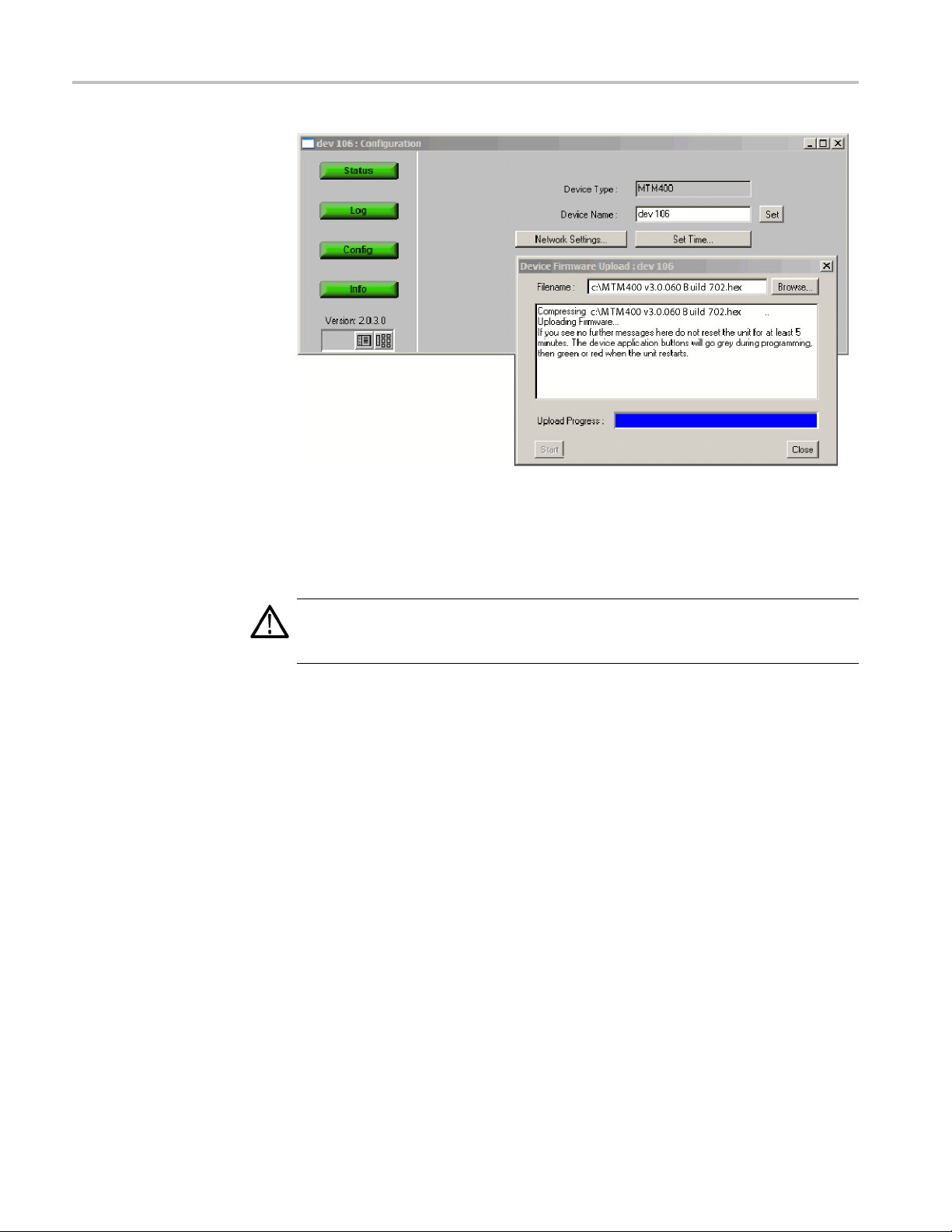
Figure 8: Device Configuration view (RUI v2.6.1 and below)
4. In the Device Configuration view, click Upload Device Firmware.This
opens the Device Firmware Upload window. (See Figure 9.)
MTM4UP Upgrade Instructions 21
Page 30

Application Firmware Upgrade
Figure 9: Device Firmware Upload window (RUI v2.6.1 and below)
5. Click Browse and navigate to the directory location where you copied the
upgrade files. Select the unzipped BIOS loader file:
MTM400 v2.0.6.1 BIOSLDR v2.07.hex.
6. After you select the BIOS upgrade file, click Start. The BIOS loading process
may take a few minutes. While the process completes, the four buttons in the
Device view will be grayed. The monitor will automatically restart when
the BIOS loading process completes.
7. When all four of the buttons in the Device view have been active (colored
red, green, or yellow) for longer than 20 seconds, and the progress bar in
the Device Firmware Upload dialog is full, the BIOS Loader is successfully
ed. (See Figure 10.)
load
CAUTION. To prevent upgrade problems that might require the monitor to be
returned to Tektronix service for reprogramming, do not proceed until all four
buttons in the Device view have been active (colored red, green, or yellow) for
more than 20 seconds.
22 MTM4UP Upgrade Instructions
Page 31

Application Firmware Upgrade
Figure 10
: Completed BIOS upload (RUI v2.6.1 and below)
Upgrade the BIOS. After the BIOS Loader is successfully loaded into the monitor,
perform the following steps to upgrade the BIOS:
CAUTION. To prevent damage to the monitor that will require the monitor to be
ed to Tektronix for repair, do not remove power or manually reboot the
return
MTM400 during the following procedures.
8. On the
PC, launch a second instance of Microsoft Internet Explorer Web
browser.
9. In th
e address bar of the Web browser, enter the following command and then
press the Enter key. (See Figure 11.)
address>/cgi−bin/biosupgrade
<IP
where <IP address> is the IP address of the monitor that you are upgrading.
Figure 11: Entering the BIOS upgrade command (RUI v2.6.1 and below)
10. After you press Enter, the BIOS upgrade process starts. The process should
take no longer than 15 seconds. After the BIOS upgrade process completes,
MTM4UP Upgrade Instructions 23
Page 32

Application Firmware Upgrade
a message is dis
Device view are active (colored red, green, or yellow).
CAUTION. Do not proceed until all four buttons in the Device view have been
active (either red, green, or yellow) for more than 20 seconds.
If the upgrade is unsuccessful, the original BIOS will be reinstated, if possible,
and the monitor will automatically restart.
11. Close the Internet Explorer, and then close the Device Firmware Upload
dialog box.
Perform the following step to verify that the BIOS version was upgraded:
Verify th
version was upgraded:
12. In the De
13. In the Device Information view, verify that the BIOS version matches the
e BIOS Upgrade. Perform the following step to verify that the BIOS
vice view, click Info to open the Information view. (See Figure 12.)
BIOS up
loader version.
played in the Web browser window and the buttons in the
Figure 12: Verifying the BIOS version (RUI v2.6.1 and below)
24 MTM4UP Upgrade Instructions
Page 33

Application Firmware Upgrade
Upgrade the Monitor
Firmware
After you verif
following steps to upgrade the application firmware installed on the monitor:
1. In the Device v
on page 21.)
CAUTION. To prevent upgrade problems that might require the monitor to be
returned to Tektronix service for reprogramming, you must clear the Device Log
immediately before uploading the firmware.
2. In the Device Log view, click Clear Log to clear the device log. A message is
displayed in the Device Log view confirming that the log has been cleared.
3. In the Device view, click Config to display the Device Configuration view.
(SeeFigure8onpage21.)
4. In the Device Configuration view, click Upload Device Firmware.This
opens the Device Firmware Upload window. (See Figure 9 on page 22.)
5. In the Device Firmware Upload window, click Browse and navigate to the
directory location where you copied the upgrade files. Select the unzipped
firmware file, for example:
MTM400 v3.0.060 Build 702.hex.
y the BIOS version and upgrade it if necessary, perform the
iew, click Log to display the Device Log view. (See Figure 7
6. After you select the firmware upgrade file, click Start.Thefirmware upgrade
process may take a few minutes. While the process completes, the four
buttons in the Device view will be grayed. The monitor will automatically
tart when the upgrade process completes.
res
7. When all four of the buttons in the Device view h ave been active (colored
d, green, or yellow) for longer than 20 seconds, and the progress bar in the
re
Device Firmware Upload dialog is full, the firmware is successfully loaded.
(See Figure 13.)
CAUTION. To prevent upgrade problems that might require the monitor to be
returned to Tektronix service for reprogramming, do not proceed until all four
buttons in the Device view have been active (colored red, green, or yellow) for
more than 20 seconds.
8. Click Close when the upgrade process is complete.
MTM4UP Upgrade Instructions 25
Page 34
Application Firmware Upgrade
Figure 13
9. If there
CAUTION. Programming of the interface card can take up to 20 minutes. Do not
remove power from or restart the monitor during that time. If the process fails,
programming will automatically restart.
: Completing the firmware upload (RUI v2.6.1 and below)
was an interface card installed in the monitor when you performed the
upgrade, the interface card will be automatically reprogrammed as soon as
the firmware has finished uploading.
The progress of the programming can be observed in the Device Log view.
The following messages will be displayed:
<Date> <Time> <Event ID> Interface card: CIP Firmware Programming
Started
<Date> <Time> <Event ID> Interface card: CIP Firmware Programming
Successful
<Date> <Time> <Event ID> Interface card: CIP Card Startup
The Input Card button on the Stream view bar will not be displayed until
programming of the interface card is complete.
26 MTM4UP Upgrade Instructions
Page 35

Application Firmware Upgrade
Enable Java Runtime
Environment
Before the firmw
Runtime Environment is available using the following steps:
1. Launch Micros
2. From the Internet Explorer menu bar, select Tool s > Internet Options...,
andthenselecttheAdvanced tab.
3. Locate the Java (Sun) node, and then select the Use JRE check box. (See
Figure 14.) Note that your version of the JRE may be later.
areupgradecanbeverified, you must ensure that the Java
oft Internet Explorer.
Figure 14: Internet Options dialog box
4. Close the Internet Options dialog box.
5. Close and restart Internet Explorer.
MTM4UP Upgrade Instructions 27
Page 36

Application Firmware Upgrade
Verify the Firmware
Upgrade
Perform the fol
NOTE. By performing the preceding firmware upgrade procedure, the RUI on
your monitor was upgraded to v3.0. To access the upgraded RUI, your PC must
meet the necessary requirements. (See Table 3.)
1. If necessary, close the Web browser window that you used to upgrade the
firmware on your monitor.
2. If necessary, reconfigure your PC to meet the requirements. (See Table 3.)
3. If necessary, p ower on the monitor and wait for it to initialize. When the
initialization process is complete, the monitor beeps and the front-panel
LEDs illuminate.
4. Using a PC connected to the same Ethernet network as the monitor, perform
the following steps to open the RUI:
NOTE. T
RUI. You can also access the RUI using the Tektronix Web Monitoring Systems
Manager (WebMSM). The instructions for using WebMSM are located in the
WebMSM User Manual (Tektronix part number 077-0116-xx).
lowing steps to verify the firmware upgrade:
his procedure uses Microsoft Internet Explorer to open the monitor
a. Launch Microsoft Internet Explorer.
b. In th
c. Press Enter. A Java applet is downloaded from the monitor and launched.
CAUTION. The Java applet will not run unless a temp directory is properly
configured on the PC. A temp directory is set up by default in the Windows XP
operating system; previous operating systems may require operator action.
The Java applet will not run unless the Sun Java Virtual Machine is installed.
Type java -version at the command prompt to verify that it is installed and that
the version is 1.6.0_03 or g reater. If it is not installed, you can download the
latest version from the Sun Web site, www.java.com.
If you have to update the Java version on the PC, you will need to restart
this procedure at step 4
e address bar of the Web browser, enter the network identity
or IP address of the monitor, for example: http://TSMonitor01 or
http://111.222.333.444.
The file size is approximately 1.5 MB; the download time will depend
on the network speed and traffic.
28 MTM4UP Upgrade Instructions
Page 37

Application Firmware Upgrade
5. After the Java a
box is displayed. (See Figure 15.)
Figure 15: Logging in to monitor (RUI v3.0 and above)
pplet is downloaded, the Connect to MTM Device dialog
6. In the Connect to MTM Device dialog box, select Administrator from
the Log
password for Administrator login type is tek.
7. Click
8. Click Device in the button bar of the RUI window to display the Device
Info
NOTE. The Device Information view details the software and hardware build
state of the monitor. The values shown in screenshots in this manual may differ
from the values shown on your display.
9. Verify that the Application Firmware Version shown in the Device Information
view matches the firmware version number listed in the file name of the *.hex
file that you copied from the application firmware CD-ROM supplied with
this kit.
in Type drop-down list, and then enter the p assword. The default
Connect to log in to the monitor and display the RUI window.
rmation view. (See Figure 17.)
MTM4UP Upgrade Instructions 29
Page 38

Application Firmware Upgrade
Figure 16: Device Information view (RUI v3.0 and above)
10. After you verify that the firmware upgrade was successful, proceed as follows:
If you are upgrading your monitor with software options or if you are
installing an MTM4UP QC (QAM Annex C) hardware upgrade, refer to
the Software Option Upgrade.(Seepage41.)
If you are not upgrading your m onitor with software options and are
installing hardware options, refer to the Hardware Option Upgrade.(See
page 57.)
If you are upgrading your monitor to firmware version 3.1 and above, refer
to the Firmware Upgrade (RUI v3.0 and Above).(Seepage31.)
NOTE. If you want to change the RUI version on your monitor to v2.6.1 after you
mpete the upgrade installation, use the instructions that are located in the
co
MTM400 and MTM400A RUI v3.x Upgrade Technical Reference (Tektronix part
number 077-0174-xx) that is supplied on the Tektronix Web site.
30 MTM4UP Upgrade Instructions
Page 39

Application Firmware Upgrade
Firmware Upgr
Identify the
Firmware Version
ade (RUI v3.0 and Above)
If your MTM400 or MTM400A monitor has RUI v3.0 or above installed, perform
the following steps to upgrade the application firmware installed on your monitor.
Current
Perform the following steps to identify the firmware version that is installed in
your monitor:
1. Power on the monitor and wait for it to initialize. When the initialization
process is complete, the monitor beeps and the front-panel LEDs illuminate.
2. Use a PC that meets the necessary requirements. (See Table 3 on page 5.)
Ensure that the PC is connected to the same Ethernet network as the monitor
and perform the following steps to open the RUI:
NOTE. This procedure uses Microsoft Internet Explorer to open the monitor
RUI. You can also access the RUI using the Tektronix Web Monitoring Systems
Manager (WebMSM). The instructions for using WebMSM are located in the
Web M SM
User Manual (Tektronix part number 077-0116-xx).
a. Launch Microsoft Internet Explorer.
b. In the address bar o f the Web browser, enter the network identity
or IP address of the monitor, for example: http://TSMonitor01 or
http://111.222.333.444.
c. Press Enter. A Java applet is downloaded from the monitor and launched.
The file size is approximately 1.5 MB; the download time will depend
the network speed and traffic.
on
CAUTION. The Java applet will not run unless a temp directory is properly
configured on the PC. A temp directory is set up by default in the Windows XP
operating system; previous operating systems may require operator action.
The Java applet will not run unless the Sun Java Virtual Machine is installed.
Type java -version at the command prompt to verify that it is installed and that
the version is 1.6.0_10 or greater. If it is not installed, you can download the
latest version from the Sun Web site, www.java.com.
If you have to update the Java version on the PC, you will need to restart
this procedure at step 2.
3. After the Java applet is downloaded, the Connect to MTM Device dialog
box is displayed. (See Figure 15.)
MTM4UP Upgrade Instructions 31
Page 40

Application Firmware Upgrade
4. In the Connect t
the Login Type drop-down list, and then enter the password. The default
password for Administrator login type is tek.
NOTE. You must log in to the monitor using the A dministrator login type. The
User login type does not have sufficient permissions to perform software option
upgrades.
5. Click Connect to log in to the monitor and display the RUI window.
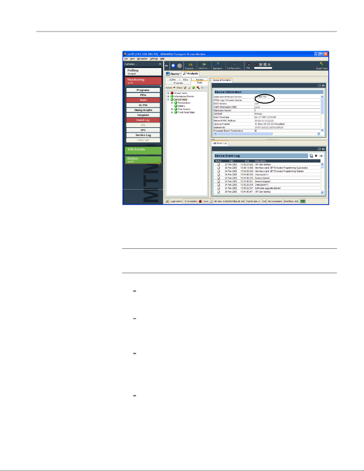
6. Click Device in the button bar of the RUI window to display the Device
Information view. (See Figure 17.)
o MTM Device dialog box, select Administrator from
32 MTM4UP Upgrade Instructions
Page 41
Application Firmware Upgrade
Figure 17: Device Information view (RUI v3.0 and above)
7. Note the Application Firmware Version value shown in the Device
Information view and proceed as follows:
NOTE. The Device Information view details the software and hardware build
state of the monitor. The values shown in screenshots in this manual may differ
he values shown on your display.
from t
If the displayed application firmware version is version 3.0 and the version
ed on the application firmware CD-ROM supplied with this kit is later,
list
refer to Install the Upgrade File on the PC.(Seepage34.)
he displayed application firmware version is earlier than version 3.0,
If t
version 3.0 must be installed before any later version is installed. Perform
the procedure described in Firmware Upgrade (RUI v2.6.1 and Below).
(See page 15.)
If the displayed application firmware version is the same version that
is listed on the application firmware CD-ROM supplied with this kit,
and you are upgrading your monitor with software options or if you are
installing an MTM4UP QC (QAM Annex C) hardware upgrade, proceed
to Software Option Upgrade. (Seepage41.)
If the displayed application firmware version is the same version that is
listed on the application firmware CD-ROM supplied with this kit, and
MTM4UP Upgrade Instructions 33
Page 42

Application Firmware Upgrade
Install the Upgrade File on
the PC
if you are not up
are installing hardware options, proceed to Hardware Option Upgrade.
(See page 57.)
Perform the following steps to copy the upgrade files from the application
firmware CD-ROM to the hard drive of your PC:
CAUTION. For the firmware upgrade to be successful, the upgrade file(s) must
be copied from the application firmware CD-ROM to a writable location such
as the hard drive on your PC.
1. Insert the application firmware CD-ROM supplied with this kit into the
CD-ROM drive of your PC.
2. Locate and copy the application firmware file from the CD-ROM to the hard
drive of your PC:
MTM400 <version number>.zip
For example: MTM400 v3.0.060 Build 702.zip
3. Unzip the upgrade file that you copied to your PC. The name of the unzipped
upgrade file should be MTM400 <version number>.hex.
grading your monitor with software options, and you
Remove Signal Sources
Upgrade the Monitor
Firmware
CAUTION. To prevent upgrade problems that might require the monitor to be
returned to Tektronix service for reprogramming, disconnect all transport stream
inputs and outputs from the monitor before performing the remaining portion of
the firmware upgrade procedure.
CAUTION. To prevent upgrade problems that might require the monitor to be
returned to Tektronix service for reprogramming, you must clear the Device Log
immediately before uploading the firmware.
1. In the Device Event Log view, click X to clear the log. (See Figure 17 on
page 33.)
2. Close the RUI browser window that you used to verify the firmware version
installed on your monitor and the opening browser window (if still open).
34 MTM4UP Upgrade Instructions
Page 43

Application Firmware Upgrade
3. Relaunch Micro
4. In the address bar of the Web browser, enter the network identity or IP address
of the monitor
5. Press Enter. A Java applet is downloaded from the monitor and launched.
The file size
the network speed and traffic.
6. After the Ja
is displayed. (See Figure 15 on page 29.)
7. In the Conn
the Login Type drop-down list, and then enter the password. The default
password for Administrator login type is tek.
NOTE. You must log in to the monitor using the Administrator login type. The
User login type does not have sufficient permissions to perform software option
upgrades.
8. In the Connect to MTM Device dialog box, click Upload Firmware to open
the Upload Device Firmware window. (See Figure 18.)
soft Internet Explorer.
, for example: http://TSMonitor01 or http://111.222.333.444.
is approximately 1.5 MB; the download time will depend on
va applet is downloaded, the Connect to MTM Device dialog box
ect to MTM Device dialog box, select Administrator from
Figure 18: Upload Device Firmware window (RUI v3.0 and above)
MTM4UP Upgrade Instructions 35
Page 44

Application Firmware Upgrade
9. In the Upload De
vice Firmware window, click Browse and navigate to the
directory location where you copied the upgrade file. Select the unzipped
firmware file, for example:
MTM400 v3.1.x.xx x Build x xx.hex
CAUTION. Do not remove power from the monitor during the reprogramming
process. If power is removed during reprogramming, the monitor might be
rendered unable to reboot, which will require that the monitor be returned to
Tektronix for repair.
10. Click Start to upload the firmware. The firmware upgrade process may take
a few minutes to complete.
NOTE. Al
though the order that firmware components are upgraded may differ
from version to version, you must allow at least 20 minutes for the process to
complete. (See Figure 1 on page 14.)
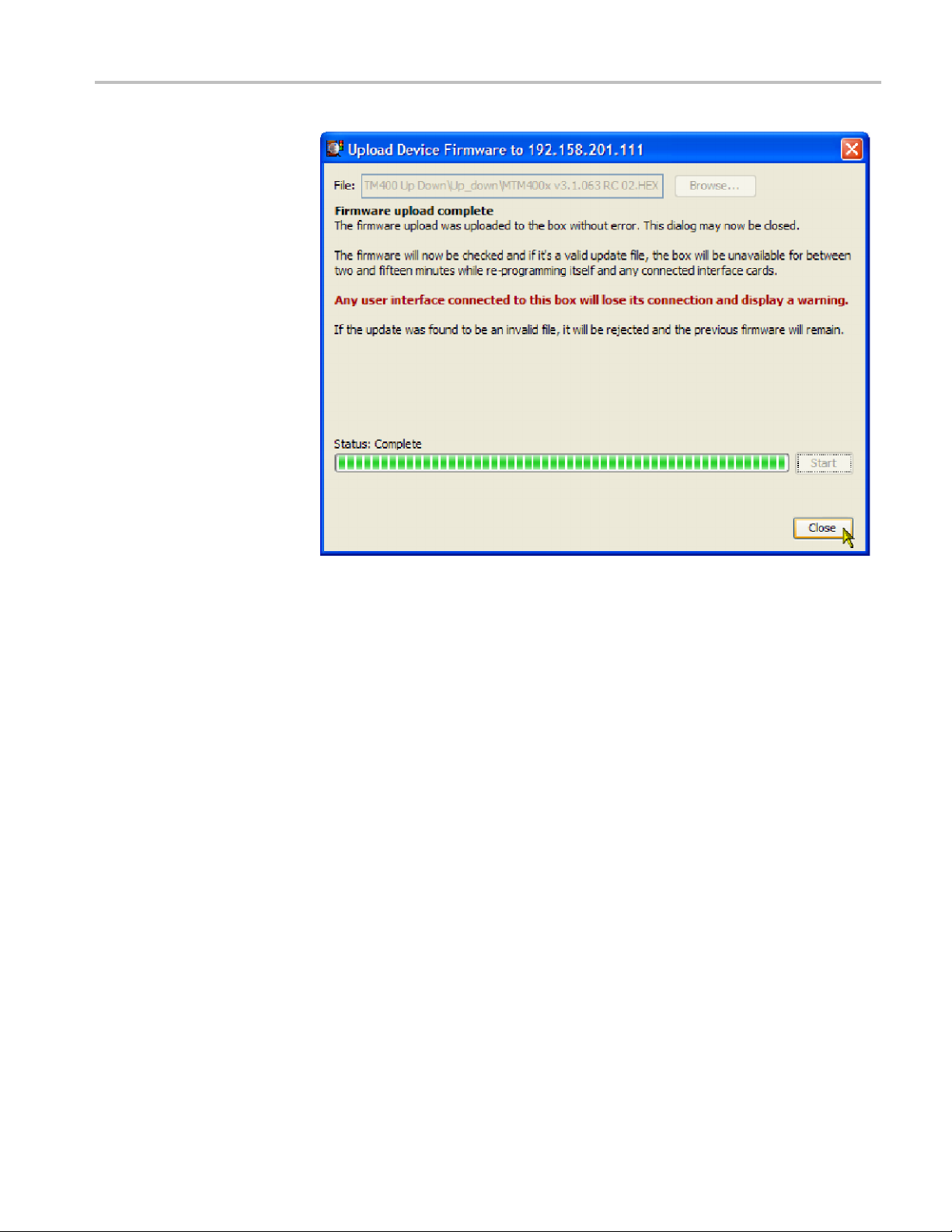
11. When the firmware upload is complete, the message Firmware upload
complete appears. (See Figure 19.)
As stated in the message, the uploaded firmware will be checked, and if valid,
reprogramming will start.
36 MTM4UP Upgrade Instructions
Page 45
Application Firmware Upgrade
Verify the Firmware
Upgrade
Figure 19: Completing the firmware upload (RUI v3.0 and above)
12. Close the Upload Device Firmware dialog box.
13. Click Connect in the Connect to MTM dialog box.
The Initializing progress window is displayed.
nterface card is installed in the monitor, it will be checked automatically
If an i
and reprogrammed if necessary. During this process, an interim progress
screen may be displayed before the RUI opens.
14. When the reprogramming process is complete, close the RUI, and if necessary,
close the associated Web browser window.
erify the firmware upgrade, perform the procedure described in Verify the
To v
Firmware Upgrade section. (See page 28.).
MTM4UP Upgrade Instructions 37
Page 46

Application Firmware Upgrade
Command Line F
irmware Upgrade
An alternative to upgrading the firmware using the MTM400A RUI is by using the
command line firmware upgrade program supplied on the MTM400A Application
Firmware CDMTM400A firmware.
CAUTION. Review and comply with the RUI Versions section before using the
command line upgrade. (See page 13.)
Use the following steps to upgrade the firmware from the command line:
1. Identify the current firmware version. (See page 13, Application Firmware
Upgrade.)
a. Power on the monitor and wait for it to initialize. When the initialization
process is complete, the monitor beeps and the front-panel LEDs
illuminate.
b. Using a PC that meets the requirements for the RUI version and is
connected to the same Ethernet network as the monitor, open the RUI as
previously described. (See Table 3 on page 5.)
c. From the RUI, identify the Application Firmware Version.
ROM. This program can be used to upgrade and downgrade the
d. Close the RUI.
Using this application firmware version information as a reference point,
identify and locate the firmware upgrade file to be used, for example,
“MTM400 v3.1.063.hex”.
2. At the PC, insert the MTM400A Application Firmware CD-ROM into the
CD-ROM drive.
3. From the Windows desktop, open the Command window, Start > Run > cmd.
4. In the command window, change to the CD-ROM directory containing the
program, mtmfwuploader.exe.
5. Enter the program command in the following format: mtmfwuploader.exe
<mtm address> <firmware file> for example,
mtmfwuploader.exe 10.0.0.1 "mtm400x v3.1.063.hex"
NOTE. When the firmware upload file name has spaces in it, enclose the name in
quotation marks, as shown in this example.
6. Execute the command by pressing the Enter key on your keyboard.
38 MTM4UP Upgrade Instructions
Page 47

Application Firmware Upgrade
Troubleshooting
The firmwa
7. The firmware upload is complete when the following message is displayed:
mtm400 a
The progress indicator following the “Waiting for interface programming to
complete” message, may go beyond 100%. If this happens, note the following
steps:
1. Ensure that the signal input is disconnected and retry the process.
2. Observe the SFP LINK LED on the GbE interface card rear panel.
CAUTION. If, with no input, the SFP LINK LED stays lit, rebooting the instrument
dresultinfirmware corruption.
coul
3. If the LED is still lit after 15 minutes, then a reboot, by removing and
nstating power, can be tried.
rei
4. If the upgrade is still unsuccessful, contact Tektronix support (www.tek.com).
re upload program will run.
nd interface card is programmed now.
rify the Firmware
Ve
Verify the firmware upgrade. (See page 28, Verify the Firmware Upgrade.)
Upgrade
MTM4UP Upgrade Instructions 39
Page 48

Application Firmware Upgrade
40 MTM4UP Upgrade Instructions
Page 49

Software Option Upgrade
The following MTM4UP upgrades require that you apply the new option key that
is supplied with the upgrade kit before the upgrade will be enabled:
All software option upgrades (MTM4UP 01, 02, 03, 04, 05, 06, and 07)
Hardware upgrade MTM4UP QC (QAM Annex C interface ca rd)
Option Keys
The option key is a unique string of alphanumeric characters of the form
nnnnn−nnnnn−nnnnn−nnnnn. A single option key can enable one or more
software options.
Each option key is unique and is generated for a specific MTM400 or MTM400A
monitor using the serial number and MAC address of that monitor. An option key
that is g
The serial number identifiesaspecific MTM400 or MTM400A monitor. The
MAC add
the monitor. If there is a hardware failure and the Transport Stream Processor
board is replaced, a new option key will need to be issued becaus e the monitor
will then have a different MAC address. The MAC address is printed on the label
on the top cover of the monitor and above the network port on the rear panel.
enerated for one monitor will not work when applied to another monitor.
ress identifies the Transport Stream Processor board that is installed in
RUI Versions
If you ordered a software option upgrade, this kit includes both a document and a
sticker with the new option key for your monitor. You will apply the sticker to the
top cover of the monitor after you verify the upgrade.
UTION. To avoid losing your software options, do not misplace the option key
CA
document or sticker that was included with this upgrade kit. If the battery-backed
RAM in your MTM400 or MTM400A monitor is reset, you must reapply the option
key to reenable any software options that were purchased for your monitor.
The version number of the firmware installed on your monitor corresponds to the
version number of the RUI. MTM400 monitors were shipped from the factory
with RUI v2.6.1 or below installed. MTM400A monitors are shipped with RUI
v3.0 or above installed. RUI v3.0 introduced new features and a significant
change in the operation of the user interface. The MTM400 and MTM400A
monitors can be modified to operate using either version of the RUI.
Use the software option upgrade procedure that is appropriate for the RUI version
that is currently installed on your monitor:
MTM4UP Upgrade Instructions 41
Page 50

Software Option Upgrade
If you did not pe
MTM400A monitor is currently operating with RUI v2.6.1 or below, perform
the procedure described in Software Option Upgrade (RUI v2.6.1 and Below).
(See page 43.)
If you performed a firmware upgrade or if your MTM400 or MTM400A
monitor is currently operating with RUI v3.0 or above, perform the procedure
described in Software Option Upgrade (RUI v3.0 and Above).(Seepage48.)
If you change the RUI version on your monitor to v2.6.1 after you install the
upgrade, you will not lose any of your software options. Instructions for changing
theRUIversionfromv3.0andabovetov2.6.1arelocatedintheMTM400and
MTM400A R
077-0174-xx) that is supplied on the Tektronix Web site.
UI v3.x Upgrade Technical Reference (Tektronix part number
rform a firmware upgrade and if your MTM400 or
42 MTM4UP Upgrade Instructions
Page 51

Software Option Upgrade
Software Opti
on Upgrade (RUI v2.6.1 and Below)
If your MTM400 or MTM400A monitor has RUI v2.6.1 or below installed,
perform the following procedure to apply the option key that was supplied with
this kit:
1. Power on the monitor and wait for it to initialize. When the initialization
process is c
2. Using a PC that meets the requirements for the RUI version and is connected
to the same
perform the following steps to open the monitor RUI:
NOTE. This procedure uses Microsoft Internet Explorer to open the monitor
RUI. You can also access the RUI using the Tektronix Web Monitoring Systems
Manager (WebMSM). The instructions for using WebMSM are located in the
WebMSM User Manual (Tektronix part n umber 077-0116-xx).
a. Launch Microsoft Internet Explorer.
b. In the address bar o f the Web browser, enter the network identity
or IP address of the monitor, for example: http://TSMonitor01 or
http://111.222.333.444.
omplete, the monitor beeps and the front-panel LEDs illuminate.
Ethernet network as the monitor, (See Table 2 on page 4.),
c. Press Enter. A Java applet is downloaded from the monitor and launched.
The file size is approximately 1.5 MB; the download time will depend
on the network speed and traffic.
TION. The Java applet will not run unless a temp directory is properly
CAU
configured on the PC. A temp directory is set up by default in the Windows XP
operating system; previous operating systems may require operator action.
The Java applet will not r un unless the Microsoft Java Virtual Machine is
installed. Type jview at the command prompt to verify that it is installed
and that the version is 5.00.3809 or greater. If it is not installed, obtain the
installation file from the Microsoft Web site.
If the Sun Virtual Machine has also been installed, the Sun Virtual Machine
must not be set as the default in the Java control panel or Internet Explorer
options, advanced tab.
3. After the Java applet is downloaded, the monitor splash screen will appear,
and then be quickly overlaid by the Login Details dialog box. (See Figure 20.)
MTM4UP Upgrade Instructions 43
Page 52

Software Option Upgrade
Figure 20: Logging in to the monitor (RUI v2.6.1 and below)
4. In the Login Details dialog box, select Administrator from the User
drop-down list.
NOTE. You must log in to the monitor using the A dministrator login type. The
User login type does not have sufficient permissions to perform software option
upgrades.
5. Enter the appropriate password, and then click OK to accept the login details.
The default password for the Administrator login type is tek.
6. After you log in to the monitor, the Hotspot view is displayed. (See
Figure 21.) Click Device to open the Device view.
Figure 21: Hotspot view (RUI v2.6.1 and below)
7. In the Device view, click Info to open the Information screen.
NOTE. For firmware versions 2.1.0 to 2.6.1, the information shown in the Device
Information view differs from the previous firmware versions.
Device Information view for firmware versions 2.0.7 and earlier - (See Figure 22.)
Device Information view for firmware versions 2.1.0 and later - (See Figure 23.)
44 MTM4UP Upgrade Instructions
Page 53

Software Option Upgrade
8. Verify that the
matches the Unique ID number listed on the option key document that was
shipped with the upgrade kit.
Figure 22: Device Information view (RUI v2.0.7 and earlier)
Network MAC Address shown in the Information screen
Figure 23: Device Information view (RUI v2.1.0 to v2.6.1)
9. Make a note of the software options that are currently enabled on the monitor.
(See Figure 23.)
NOTE. After you upgrade the monitor, you will verify the upgrade by checking
that all of the current software options are still enabled and that the new option(s)
you p urchased has been enabled.
10. In the Device view, click Config to open the Configuration screen. (See
Figure 24.)
MTM4UP Upgrade Instructions 45
Page 54

Software Option Upgrade
Figure 24: Device view Configuration screen (RUI v2.6.1 and below)
11. In the Configuration screen, click Upload License to open the License Upload
dialog box. ( See Figure 25.)
e 25: License Upload dialog box (RUI v2.6.1 and below)
Figur
CAUTION. The option key string is case-sensitive and must be entered exactly as it
appears on the option key document, including any dashes.
12. In the License Upload dialog box, enter the option key that was supplied with
the upgrade kit, and then click Upload.
13. Progress messages will be displayed in the License Upload dialog box as
the new option key is loaded into the monitor. When the message "License
upload ok" is displayed, click the Close button.
NOTE. If the option key is rejected, the message "License upload error -
invalid license" will appear in the License Upload dialog box. (See page 52,
Troubleshooting.)
46 MTM4UP Upgrade Instructions
Page 55

Software Option Upgrade
14. The License Cha
Click OK to restart the monitor.
Figure 26: L
If the opti
by the new option key will be implemented after the monitor restarts. If the
option key upload was rejected, the restart will reinstate the software options
(if any) that were enabled by the option key previously loaded in the monitor.
NOTE. During the monitor restart, all of the RUI screens will remain open, but
the buttons will be grayed out until the restart process is completed.
15. If the option key upload was accepted, verify the option upgrade after the
monitor restarts. (See page 52, Verifying the Software Option Upgrade.)
icense Changed dialog box (RUI v2.6.1 and below)
on key upload was accepted, the licensed software options enabled
nged dialog box is displayed. (See Figure 26.)
MTM4UP Upgrade Instructions 47
Page 56

Software Option Upgrade
Software Opti
on Upgrade (RUI v3.0 and Above)
If your MTM400 or MTM400A monitor has RUI v3.0 or above installed, perform
the following procedure to apply the option key that was supplied with this kit:
1. Power on the monitor and wait for it to initialize. When the initialization
process is complete, the monitor beeps and the front-panel LEDs illuminate.
2. Using a PC that meets the requirements for the RUI version and is connected
to the same Ethernet network as the monitor, perform the following steps to
open the RU
NOTE. This procedure uses Microsoft Internet Explorer to open the monitor
RUI. You can also access the RUI using the Tektronix Web Monitoring Systems
Manager (WebMSM). The instructions for using WebMSM are located in the
WebMSM User Manual (Tektronix part number 077-0116-xx).
a. Launch Microsoft Internet Explorer.
b. In the address bar of the Web browser, enter the network identity
or IP address of the monitor, for example: http://TSMonitor01 or
http://111.222.333.444.
c. Press Enter. A Java applet is downloaded from the monitor and launched.
The file size is approximately 1.5 MB; the download time will depend
on the network speed and traffic.
I. (See Table 3 on page 5.):
CAUTION. The Java applet will not run unless a temp directory is properly
figured on the PC. A temp directory is set up by default in the Windows XP
con
operating system; previous operating systems may require operator action.
e Java applet will not run unless the Sun Java Virtual Machine is installed.
Th
Type java -version at the command prompt to verify that it is installed and that
the version is 1.6.0_10 or g reater. If it is not installed, you can download the
latest version from the Sun Web site, www.java.com.
If you have to update the Java version on the PC, you will need to restart
this procedure at step 2.
3. After the Java applet is downloaded, the Connect to MTM Device dialog
box is displayed. (See Figure 27.)
48 MTM4UP Upgrade Instructions
Page 57

Software Option Upgrade
Figure 27: Logging on to MTM400A monitor (RUI v3.0 and above)
4. In the Connect to MTM Device dialog box, select Administrator from
the Login Type drop-down list, and then enter the password. The default
passwo
NOTE. You must log in to the monitor using the Administrator login type. The
User login type does not have sufficient permissions to perform software option
upgrades.
5. Click Connect to log on to the monitor and display the RUI window.
6. Click Device in the button bar of the RUI window to display the Device
Information view. (See Figure 28.)
7. Verify that the Network MAC Address shown in the Device Information view
matches the Unique ID number listed on the option key document that was
shipped with the upgrade kit.
8. Make a note of the software options that are currently enabled on the monitor.
The following illustration shows that the monitor has software options 01, 02,
and 03 enabled.
rd for Administrator login type is tek.
NOTE. After you upgrade the monitor, you will verify the upgrade by checking
that all of the current software options are still enabled and that the new option(s)
you p urchased has been enabled.
MTM4UP Upgrade Instructions 49
Page 58

Software Option Upgrade
Figure 28: Device Information view (RUI v3.0 and above)
9. After you verify the MAC address and note the installed s oftware options,
close the RUI window, repeat steps 2 through 10 to redisplay the Connect to
MTM Device dialog box, and then proceed to step 10.
NOTE.
to MTM Device dialog box that appears before the monitor RUI is launched.
Only advanced users should use the Connect to MTM Device dialog box that is
accessed from the Connect button in the monitor RUI toolbar.
10. In the Connect to MTM Device dialog box, click Upload License to open
CAUTION. The option key string is case-sensitive and must be entered exactly as it
appears on the option key document, including any dashes.
11. In the Upload License dialog box, enter the new option key that was supplied
12. Click Ye s to confirm the upload in the Upload License message box. (See
You should initiate the s oftware options upgrade process from the Connect
the Upload License dialog box. (See Figure 29.)
with this kit, and then click Upload.
Figure 30.)
50 MTM4UP Upgrade Instructions
Page 59

Figure 29: Upload license dialog box (RUI v3.0 and above)
Software Option Upgrade
Figure 30: Upload license message box (RUI v3.0 and above)
13. Progress messages will be displayed in the Upload License dialog b ox as the
new option key is loaded into the monitor:
If the option key is accepted, the message "License upload ok" appears,
and then the monitor automatically reboots. The reboot process
ements the software options enabled by the new option key. The
impl
message "Reboot complete" appears after the monitor reboots.
he option key is rejected, the message "License upload error - invalid
If t
license" appears in the Upload License dialog box. (See page 52,
Troubleshooting.)
14. If the option key was accepted, click Close to close the Upload License dialog
box, and verify the option upgrade. (See page 52, Verifying the Software
Option Upgrade.)
MTM4UP Upgrade Instructions 51
Page 60

Software Option Upgrade
Troubleshooting
If the option key upload is rejected, the message “License upload error - invalid
license” a ppears in the Upload License dialog box. Use the following steps
to correct the problem:
Reenter the option key in the Upload L icense dialog box. The option key
string is case-sensitive and must be entered exactly as it appears on the option
key document, including any dashes.
Inspect the option key documentation that was supplied with the upgrade kit
and verify that you are applying the option key to the MTM400 or MTM400A
monitor l
If you are upgrading a monitor that is connected to a network containing more
than one
correct monitor. Select Info in the Device view and verify that the MAC
Address of the monitor matches the Unique ID number listed on the option
key documentation supplied with the upgrade kit.
If the upgrade is still unsuccessful, contact Tektronix Technical Support with
the following information available to you:
isted in the documents.
MTM400 or MTM400A monitor, ensure that the RUI is viewing the
Serial Number of the MTM400 or MTM400A monitor
MAC Address of the TS processor board
on key string that was supplied with the upgrade kit
Opti
Option k ey string that was previously assigned to the monitor (should be
ted on the label attached to the top cover of the monitor)
lis
Verifying the Software Option Upgrade
e to differences in the RUI versions that were shipped on the MTM400 and
Du
MTM400A monitors, separate verification instructions for the RUI versions are
provided.
Upgrade Verification (RUI
v2.6.1 and below)
If RUI v2.6.1 or below is installed on your monitor, perform the following steps
to verify the software option upgrade:
1. If you logged off the monitor after you performed the upgrade, perform steps 1
through 7 starting on (See page 43.). Otherwise, in the Device view of the
upgraded monitor, click Info to open the Information screen. (See Figure 31.)
2. Verify that all of the software options that were enabled on the monitor prior
to the upgrade are still enabled.
3. Verify that the new software options you purchased with this upgrade are now
enabled. Those options are listed on the option key documentation.
52 MTM4UP Upgrade Instructions
Page 61

Software Option Upgrade
For example, op
are still enabled as they were prior to the upgrade. (See Figure 23.) and
(See Figure 31.)
CAUTION. When it is necessary after a repair, the Tektronix service center uses
the option key listed on the monitor label to reenable the software options for your
monitor. If you do not apply the new option key label supplied with the upgrade
kit to the to
the monitor might be returned to you without all of your software options enabled.
4. After you
option-key label from the sticker that was supplied with the upgrade kit to
the top cover of the monitor, covering over the previous option key listed
on the monitor label.
5. Apply the option-upgrade label from the sticker that was supplied with the
upgrade kit to the top cover of the monitor next to the options listed on the
monitor label.
p cover of the monitor and your monitor is sent to Tektronix for repair,
tions 04 and 05 were enabled, but options 01, 02, and 03
verify that the proper software options are enabled, apply the
Figure 31: Device view Information screen (RUI v2.6.1 and below)
MTM4UP Upgrade Instructions 53
Page 62

Software Option Upgrade
Upgrade Verification (RUI
v3.0 and above)
Figure 32: Device Information view (RUI v3.0 and above)
If RUI v3.0 or above is installed on your monitor, perform the following steps
to verify the software option upgrade:
1. Perform steps 1 through 6 to display the Device Information view. (See
Figure 32.)
2. Verify that all of the software options that were enabled on the monitor prior
to the upgrade are still enabled.
3. Verify that the new software options you purchased with this upgrade are now
enabled. Those options are listed on the option key documentation.
For example, options 04 and 05 were enabled, but options 01, 02, and 03
are still enabled as they were prior to the upgrade. (See Figure 23.) and
ee Figure 32.)
(S
CAUTION. Be sure to apply the option key label from the Product Upgrade sticker.
When it is necessary after a repair, the Tektronix service center uses the option key
listed on the monitor label to reenable the software options for your monitor. If
you do not apply the new option key label supplied with the upgrade kit to the top
cover of the monitor and your monitor is sent to Tektronix for repair, the monitor
might be returned to you without all of your software options enabled.
54 MTM4UP Upgrade Instructions
Page 63

Software Option Upgrade
4. After you verif
option-key label from the Product Upgrade sticker that was supplied with
the upgrade kit to the top cover of the monitor, covering over the previous
option k ey listed on the monitor label.
5. Apply the option-upgrade label from the Product Upgrade sticker to the top
cover of the monitor next to the options listed on the monitor label.
6. If your upgrade includes the installation of a hardware option, refer to the
hardware option upgrade section. (See page 57, Hardware Option Upgrade.)
Otherwise, proceed to WebMSM software upgrade section. (See page 79,
WebMSM So
y that the proper software options are enabled, apply the
ftware Upgrade.)
MTM4UP Upgrade Instructions 55
Page 64

Software Option Upgrade
56 MTM4UP Upgrade Instructions
Page 65

Hardware Option Upgrade
If you did not purchase a new interface card and only purchased an SFP module
for your GbE interface card (MTM4UP options LX, SX, or ZX), proceed to Install
the SFP Modul
The following instructions describe how to install the new interface card that
was supplie
disassembling or reassembling the product, contact your nearest Tektronix Service
Center or Tektronix Factory Service for assistance.
There are older version interface cards that were available with the MTM400
monitor, which have been replaced with newer versions that are available with
the MTM400A monitor. Those older version interface cards will continue to
operate properly if they are installed in the MTM400A monitor. The following
procedure includes instructions for replacing those older version interface cards.
In the pr
older version interface cards; QAM (Annex B2) and 8PSK/QPSK refe r to the
newer version interface cards.
Since only one signal-interface card can be installed at a time in the monitor,
the installation instructions describe how to remove the currently installed
signal-interface card if one exists in your monitor.
e (GbE Interface Only) section. (See page 71.)
d with your hardware upgrade. If you need further details for
ocedure, QAM (Annex B1) and QPSK (L-Band, old version) refer to the
The steps involved to install or replace the interface cards are similar between the
various cards; any differences are indicated in the procedure. You will perform
the following activities to install the new interface card:
If neces sary, remove the existing interface card
Install the new interface card
If required for your interface card, install the RF cable
f required for your GbE interface card, install the SFP optical-port module
I
Configure the monitor for the new interface card (this will verify the hardware
pgrade)
u
Configure the new interface card
MTM4UP Upgrade Instructions 57
Page 66

Hardware Option Upgrade
Preparation
1. Upgrade the monitor firmware. (See page 13, Application Firmware
Upgrade.)
CAUTION. For MTM400 monitors only, to pre vent installation failure of the GbE
interface card, install the application firmware provided in the upgrade kit before
you install
2. If necessary, disconnect any signal and power cables from the monitor,
remove the
on a static-free workbench.
WARNING. To prevent serious injury or loss of life from electrical shock, do not
operate the monitor with the top cover or panels removed. Disconnect power from
the monitor before removing the top cover or panels.
the GbE interface card.
monitor from the instrument rack, and then place the monitor
CAUTION. Only qualified personnel should perform the following procedure.
Read the Service Safety Summary and the General Safety Summary at the front of
this manual before performing this procedure.
To prevent static discharge damage, service the product only in a static-free
environment. Observe standard handling precautions for static-sensitive devices
e installing this kit. Always wear a grounded wrist strap, grounded foot strap,
whil
and static resistant apparel while installing this kit.
ot use unnecessary force to disconnect or insert connectors.
Do n
Install the New Interface Card
Complete the preparation procedure. (See page 58, Preparation.) Perform the
following steps to install the interface card that was supplied with your upgrade kit:
Remove the Mon itor Cover
1. Remove the 21 cover retaining screws and set them aside. (See Figure 33.)
2. Lift the cover clear of the monitor.
58 MTM4UP Upgrade Instructions
Page 67
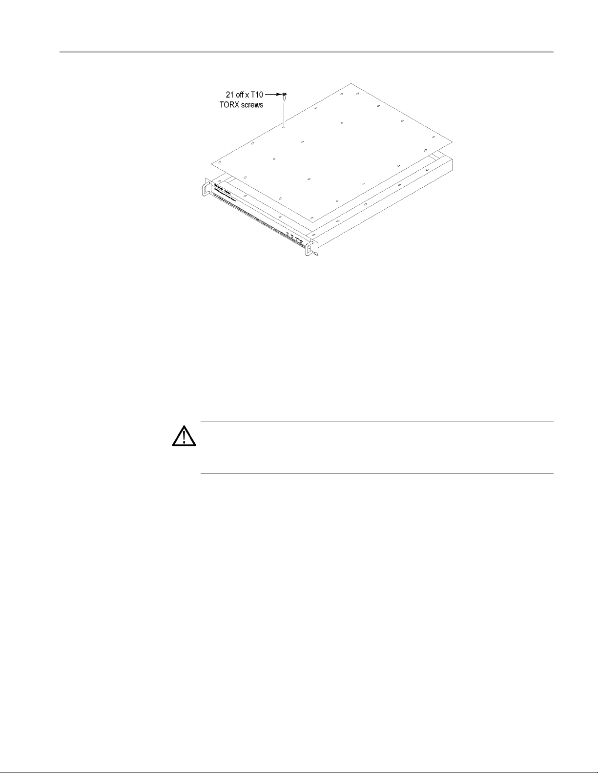
Figure 33: Removing the monitor cover
Hardware Option Upgrade
Remove the Installed
Interface Card
3. Locate the interface card in your monitor. (See Figure 34.) and (See
Figure 35.) The interface card is mounted on the right side of the monitor as
viewed from the rear.
4. If your monitor does not have an interface card already insta lled, proceed to
step 11.
5. If your monitor has an interface card already installed, determine which type
of card is installed. (See Figure 34.) (See Figure 35.) (See Figure 36.)
CAUTION. To avoid incorrectly installing the interface card, be sure to follow the
removal directions for the type of interface card that is installed in your monitor.
e are three types of interface cards. Each card type has different cable
Ther
connections. (See Figure 34.) (See Figure 35.) (See Figure 36.)
6. If a
QAM (Annex A), QAM (Annex B1), QAM (Annex C), or QPSK
(L-Band, old version) interface card is currently installed, perform the
following steps. The table describes the cable connections to these interface
cards. (See Table 16.) Otherwise, proceed to step 7.
a. Disconnect the two coaxial cables from the SMB connectors labeled I/P
and O/P. (See Figure 34.)These are push-fit connectors.
b. If you are going to install a QAM (Annex B2), 8PSK/QPSK, DVB-S2,
8VSB, or COFDM interface card, completely remove the two coaxial
MTM4UP Upgrade Instructions 59
Page 68

Hardware Option Upgrade
cables by remov
ing them from the connectors labeled I/P A and O/P A
on the TS Processor card.
NOTE. Leave the two coaxial cables connected to the TS Processor card if
you are going to install a QAM (Annex A), QAM (Annex B1), QAM (Annex
C), or QPSK (L-Band, old version) interface card.
c. Disconnect the eight-wire power cable from the connector labeled J7
on the interface card.
d. Proceedtostep9.
Table 16: QAM (Annex A), QAM (Annex B1), QAM (Annex C), and QPSK (L-Band, old version) card connectors
e card connection
Interfac
(See Figure 34.) Cable type Connects to location Function
P1 Eight wi
O/P
I/P
Miniature coaxial
Miniature coaxial
res
J7 on P ow
I/PAon
O/PAon
er Distribution car
TS Processor card
TS Processor card
Power
d control (serializer)
Data an
d control (serializer)
Data an
Figure 34: QAM (Annex A), QAM (Annex B1), QAM (Annex C), and QPSK
(L-Band, old version) interface card location
60 MTM4UP Upgrade Instructions
Page 69

Hardware Option Upgrade
Figure 35
card location
Figure 36: GbE interface card installation
: QAM (Annex B2), 8PSK/QPSK, DVB-S2, 8VSB, and COFDM interface
MTM4UP Upgrade Instructions 61
Page 70

Hardware Option Upgrade
7. If a QAM (Annex B
2), 8PSK/QPSK, DVB-S2, 8VSB, or COFDM interface
card is currently installed, perform the following steps. The cable connections
are described in the table. (See Table 17.)
a. Disconnect the ribbon cable from the connector labeled J14 on the
interface card. (See Figure 35.)
b. If you are going to install a QAM (Annex A), QAM (Annex B1), QAM
(Annex C), or QPSK (L-Band, old version) interface card, completely
remove the ribbon cable by removing it from the connector labeled J750
on the TS Processor card.
NOTE. Leave the ribbon cable connected to the TS Processor card if you are
going to i
nstall a QAM (Annex B2), 8PSK/QPSK, DVB-S2, 8VSB, or COFDM
interface card.
c. Disconn
ect the eight-wire power cable from the connector labeled JR1
on the interface card.
d. Procee
dtostep9.
Table 17: QAM (Annex B2), 8PSK/QPSK, DVB-S2, 8VSB, and COFDM i nterface card connectors
Interface card connection
(See Figure 35.) Cable type Connects to location Function
JR1 Eight wires J7 on Power Distribution card Power
J14 Ribbon
J750 on TS Processor card
Data and control
8. If a GbE interface card is currently installed, perform the following steps. The
cable connections are described in the table. (See Table 18.)
a. Disconnect the ribbon cable from the connector labeled J10 on the
interface card. (See Figure 36.)
b. If you are going to install a QAM (Annex A), QAM (Annex B1), QAM
(Annex C), or QPSK (L-Band, old version) interface card, completely
emove the ribbon cable by removing it from the connector labeled J750
r
on the TS Processor card.
NOTE. Leave the ribbon cable connected to the TS Processor card if you are
going to install a QAM (Annex B2), 8 PSK/QPSK, DVB-S2, 8VSB, or COFDM
interface card.
c. Disconnect the eight-wire power cable from the connector labeled J8
on the interface card.
62 MTM4UP Upgrade Instructions
Page 71

Hardware Option Upgrade
Table 18: GbE in
Interface card connection
(See Figure 36.) Cable type Connects to location Function
J8 Eight wires J7 on Power Distribution card Power
J10 Ribbon
terface card connectors
J750 on TS Processor card Control Data
9. Remove the retaining screws from the interface card as described below:
a. For QAM (Annex A), QAM (Annex B1), QAM (Annex C), and QPSK
(L-Band, old version) interface cards, remove the four retaining screws
from the card and remove the three retaining screws from the rear panel.
(See Figure 37.)
b. For QAM (Annex B2), 8PSK/QPSK, DVB-S2, 8VSB, and COFDM
interface cards, remove the six retaining screws from the card and remove
the thre
e retaining screws from the rear panel. (See Figure 38.)
c. For GbE interface cards, remove the six retaining screws from the card and
remove
the three retaining screws from the rear panel. (See Figure 39.)
Figure 37: Retaining screw locations for QAM (Annex A), QAM (Annex B1), QAM
(Annex C), and QPSK (L-Band, old version) interface cards
MTM4UP Upgrade Instructions 63
Page 72

Hardware Option Upgrade
Figure 38
8VSB, and COFDM interface cards
: Retaining screw locations for QAM (Annex B2), 8PSK/QPSK, DVB-S2,
64 MTM4UP Upgrade Instructions
Page 73

Hardware Option Upgrade
all the New Interface
Inst
Card
Figure 39
10. Lift the
surface.
CAUTION. To prevent static damage to the removed card, be sure to store the card
in static-free packaging. Failure to properly store the card may result in the card
needing repair before it will operate properly when reinstalled.
11. If an interface card was not previously installed in the monitor, a blank cover
is installed on the right side of the rear panel (as viewed from the rear of
the monitor). If your monitor has a blank cover, remove the three retaining
scr
12. Place the new interface card into the right side of the monitor (as viewed from
e rear of the monitor). (See Figure 34.) (See Figure 35.) (See Figure 36.)
th
13. Line up the mounting points and install the retaining screws as described
elow:
b
a. For QAM (Annex A), QAM (Annex B1), QAM (Annex C), and QPSK
: Retaining screw locations for GbE interface card
interface card clear of the monitor and place the card on a static-free
ews and remove the blank cover.
L-Band, old version) interface cards, install the four retaining screws
(
MTM4UP Upgrade Instructions 65
Page 74

Hardware Option Upgrade
in the card and i
Figure 37.)
b. For QAM (Annex
interface cards, install the six retaining screws in the card and install the
three retaining screws in the rear panel. (See Figure 38.)
c. For GbE interface cards, install the six retaining screws in the card and
install the three retaining screws in the rear panel. (See Figure 39.)
14. Connect the signal and power cables as follows:
CAUTION. To prevent damage to the interface card connectors, do not use
unnecessary force to connect the cables. All of the connectors are polarized and
they will only fit into their respective socket in one way.
a. For QAM (Annex A), QAM (Annex B1), QAM (Annex C), and
QPSK (L-Band, old version) interface cards, make the following cable
connections. (See Table 16 on page 60.)
Connect one coaxial cable from the connector labeled O/P on the
interface card to the connecter labeled I/P A on the TS Processor card.
This i
nstall the three retaining screws in the rear panel. (See
B2), 8PSK/QPSK, DVB-S2, 8VSB, and COFDM
s a push-fit connector. (See Figure 40.)
Connect the other coaxial cable from the connector labeled I/P on the
rface card to the connecter labeled O/P A on the TS Processor card.
inte
Connect the eight-wire power cable from P1 on the interface card to J7
he Power Distribution card.
on t
66 MTM4UP Upgrade Instructions
Page 75

Hardware Option Upgrade
Figure 40
(Annex C), and QPSK (L-Band, old version) interface cards
b. For QAM (Annex B2), 8PSK/QPSK, DVB-S2, 8VSB, and COFDM
interface cards, make the following cable connections. (See Table 17
on page 62.)
: Cable connections for QAM (Annex A), QAM (Annex B1), QAM
Connect the ribbon cable from the connector labeled J14 on the
interface card to the connecter labeled J750 on the TS Processor card.
(See Figure 41.)
Connect the eight-wire power cable from JR1 on the interface card to
J7 on the Power Distribution card.
Verify that the two coaxial cables on the interface card are firmly
attached to their connectors.
MTM4UP Upgrade Instructions 67
Page 76

Hardware Option Upgrade
Figure 41: Cable connections for QAM (Annex B2), 8PSK/QPSK, DVB-S2,
8VSB, and COFDM interface cards
c. For GbE interface cards, make the following cable connections. (See
Table 1
8onpage63.)
Connect the ribbon cable from the connector labeled J10 on the
face card to the connecter labeled J750 on the TS Processor card.
inter
(See Figure 42.)
ect the eight-wire power cable from J8 on the interface card to J7
Conn
on the Power Distribution card.
68 MTM4UP Upgrade Instructions
Page 77

Hardware Option Upgrade
Reinstall the Monitor Cover
Connect the ASI Cable
Figure 42: Cable connections for GbE interface card
15. Line up the monitor top cover and replace the 21 retaining screws. (See
Figure33onpage59.)
The GbE interface card is shipped with an ASI cable that enables you to monitor
ASI and IP signals. The QAM (Annex B2), 8PSK/QPSK, DVB-S2, 8VSB, and
COFDM interface cards are shipped with an ASI cable that enables you to monitor
ASI and RF signals (for example, both the input and output of a modulator).
NOTE. The QAM (Annex A) and QAM (Annex C) interface cards do not need
xternal cable connection since these interface cards are connected to the
an e
Transport Stream Processor card inside the monitor.
MTM4UP Upgrade Instructions 69
Page 78

Hardware Option Upgrade
16. For QAM (Annex A
Hardware Upgrade section. (See page 72.)
17. For GbE interf
a. Connect the ASI cable supplied with this kit between the
ASI/SMPTE3
connector on the TS Processor card. (See Figure 43.)
b. If you purch
options LX, SX or ZX), p roceed to Install the SFP Module (GbE Interface
Only). (Seepage71.)
c. If you did not purchase an SFP module, proceed to Verify the Hardware
Upgrade. (Seepage72.)
) and QAM (Annex C) interface cards only, Verify the
ace cards only:
10M Out connector on the interface card and the ASI In
ased an SFP module for the GbE interface card (MTM4UP
Figure 43: Connecting the ASI cable − GbE interfaces
18. For QAM (Annex B2), QPSK/8PSK, DVB-S2, 8VSB, and COFDM interface
cards only:
a. Connect the ASI cable supplied with this kit between the
ASI/SMPTE310M Out connector on the interface card and the ASI In
connector on the TS Processor card. (See Figure 44.)
b. Proceed to Verify the Hardware Upgrade. (Seepage72.)
Figure 44: Connecting the ASI cable − QAM (Annex B2), QPSK/8PSK, DVB-S2, 8VSB, and COFDM interfaces
70 MTM4UP Upgrade Instructions
Page 79

Hardware Option Upgrade
Install the SF
P Module (GbE interface Only)
If you purchased an SFP module for your GbE interface card (MTM4UP options
LX, SX, or ZX), perform the following steps to install the SFP module. (See
Figure 45.)
WAR N ING. To prevent possible exposure to hazardous laser radiation, use only
Class 1 lasers as defined in the USA Federal Regulations CDRH 21 CFR 1040
and IEC/EN 60825/A2:2001.
Figure 45: SFP module and optical port plug
CAUTION. To prevent damage to the SFP module, remove power from the monitor
before removing or inserting the SFP module.
1. If necessary, remove power from the monitor.
2. Insert the SFP module into the rear-panel SFP 1000 connector. (See
Figure 46.) When fully inserted, the SFP module is latched in position.
WAR N ING. To prevent possible exposure to hazardous laser radiation, be sure to
tall the optical port plug in the SFP module when no signal cable is connected
ins
to the SFP module.
3. Proceed to Verify the Hardware Upgrade.(Seepage72.)
Figure 46: SFP module − installed
MTM4UP Upgrade Instructions 71
Page 80

Hardware Option Upgrade
Verify the Har
Verifying
Interface Card
dware Upgrade
This section provides two procedures to verify the hardware upgrade:
If you installed an interface card, perform the steps described in Signal
Interface Card Upgrades.
If you installed an SFP module in your GbE interface card, perform the steps
described in Verifying SFP Module Upgrades (GbE Interface Only).(See
page 75.)
To verify that the new interface card you installed is functioning correctly,
Upgrades
perform the following procedure:
NOTE. This procedure assumes that you upgraded the monitor firmware to version
3.0 or ab
1. Power on the monitor and log in as described in Firmware Upgrade (RUI
v3.0 and Above) steps 1 through 5.
When the monitor is first powered on after an interface card is installed, the
firmware on the interface card will be checked, and if required, reprogramming
of the monitor will start. The reprogramming process can take up to
15 minutes.
ove before installing the new interface card.
CAUTION. Do not remove power from the monitor during the reprogramming
cess. If power is removed during reprogramming, the monitor might be
pro
rendered unable to reboot, which will require that the monitor be returned to
Tektronix for repair.
2. Connect a known good, transport stream input to the interface card in your
monitor that is suitable for the type of interface card that you installed.
3. Click the Interface button in the toolbar to open the Interface dialog box.
(See Figure 47.)
72 MTM4UP Upgrade Instructions
Page 81

Hardware Option Upgrade
4. Select the desi
shows the 8VSB interface being selected. (See Figure 47.)
NOTE. If the required interface type is not available in the drop-down list, one
of the following events has occurred:
Insufficient time was allowed for the interface card to be detected and
programmed. The reprogramming process must complete before the new interface
card will be recognized.
The start-up routine failed to detect the new interface card after 15 minutes.
Remedy: Power down the monitor and reapply power.
The interface card was not installed correctly in the monitor. Remedy: After
powering down and disconnecting any cables, remove the top cover and verify the
presence of the board and its connections. Replace the top cover, reconnect any
cables t
o the monitor, and apply power.
red interface from the Interface drop-down list. The illustration
igure 47: Interface dialog box (RUI v3.0 and above)
F
fter you select the desired interface card type, you can configure the
5.A
interface card for your specific monitoring application using the Interface
MTM4UP Upgrade Instructions 73
Page 82

Hardware Option Upgrade
Settings porti
column, and then click OK or Apply.
NOTE. Refer to the MTM400A MPEG Transport Stream M onitor Technical
Reference for detailed information about the configuration settings for the type of
interface card installed in your instrument.
Refer to the MTM400A MPEG Transport Stream Monitor Specifications
and Performance Verification Technical Reference for information about the
specifications for the type of interface card installed in your instrument.
6. When you successfully select the interface type that you installed from the
Interface drop-down list, you have verified the installation of the new interface
card. Ap
was supplied with the upgrade kit to the top cover of the monitor next to the
options listed on the monitor label.
NOTE. The following note applies only if you purchased a hardware option
upgrade and did not purchase a software option upgrade with this kit.
7. If you installed a GbE interface card and also purchased an SFP module
(MTM4UP option LX, SX, or ZX), proceed to Verifying SFP Module
Upgrades (GbE Interface Only). (Seepage75.)
on of the Interface dialog box. Make any changes in the Value
ply the Option Upgrade label from the Product Upgrade sticker that
8. Otherwise, proceed to WebMSM Software Upgrade. (See page 79.)
74 MTM4UP Upgrade Instructions
Page 83

Hardware Option Upgrade
Verifying SFP Module
Upgrades (GbE Interface
Only)
To verify that t
functioning correctly, perform the following procedure:
1. If necessary,
a. Remove the optical port plug from the SFP module. (See Figure 45 on
page 71.)
b. Insert the optical cable into the SFP module. When fully inserted, the
cable conne
Figure 48: Optical cable connected to SFP module
2. If necessary, power on the monitor and log in to open the RUI window as
described in Firmware Upgrade (RUI v3.0 and Above) steps 1 through 5.
he new SFP module you installed in the GbE interface card is
connect an IP over optical signal to the GbE interface card:
ctor is latched in position. (See Figure 48.)
3. After you open the RUI window, click the Interface toolbar icon to open the
Interface dialog box.
4. In the Interface dialog box, select GbE from the Interfaces drop-down list,
and then select Auto 1000(Optical) from the Select Speed drop-down list.
(See Figure 49.)
5. Close the Interface dialog box.
MTM4UP Upgrade Instructions 75
Page 84

Hardware Option Upgrade
Figure 49: Selecting the interface card speed in the Interface dialog box
6. In the RUI window, click the Analysis tab, and then click the Interface tab.
7. Click
Add Graph on the Graphs tab, and then select Traffic from the
Available Graphs drop-down list. (See Figure 50.)
76 MTM4UP Upgrade Instructions
Page 85

Hardware Option Upgrade
Figure
50: Selecting the Trafficgraph
8. Ver if
y that the monitor displays information about the program(s) contained
on the transport stream signal in the Traffic graph. (See Figure 51.) The
example transport stream in the illustration below contains one program.
MTM4UP Upgrade Instructions 77
Page 86

Hardware Option Upgrade
Figure
51: Viewing the Trafficgraph
9. If the
10. Proceed to WebMSM Software Upgrade.(Seepage79.)
monitor displays information about the IP over optical signal in the
Traffic graph, then the SFP module is installed and operating properly. Apply
the Option Upgrade label from the Product Upgrade sticker that was supplied
with the upgrade kit to the top cover of the monitor next to the options listed
on the monitor label.
78 MTM4UP Upgrade Instructions
Page 87

WebMSM Software Upgrade
NOTE. A fully licensed version of the WebMSM Monitoring System Manager is
available to
installed. The WebMSM software enables you to monitor transport streams on
multiple MTM400 and MTM400A monitors from a single PC.
If you use the WebMSM software, and you upgrade the firmware on your monitor,
you must reinstall WebMSM and the WebMSM Configuration Editor as part of
the upgrade. All configuration files and enabled options will be retained.
Upgrading the WebMSM Software
Perform the following steps to upgrade the WebMSM software:
users of MTM400 or MTM400A monitors with RUI v3.0 or above
Download the WebMSM
Software
Install the WebMSM
Software
Technical Support
1. On the PC that you use to connect to MTM400 or MTM400A monitors,
download the latest WebMSM software package for RUI v3.0 or above from
the Tektronix Web site: www.tektronix.com/software.
2. Run Setup for the WebMSM application.
If you have a version of the WebMSM application already installed on your
PC, it will be uninstalled automatically.
3. Follow the on-screen instructions and install the WebMSM application using
the upgrade files that you downloaded to your PC.
4. Run Setup for the WebMSM Configuration Editor application.
If you have a version of WebMSM Configuration Editor already installed on
your PC, it will be uninstalled automatically.
5. Follow the on-screen instructions and install the WebMSM Configuration
Editor using the upgrade files that you downloaded to your PC.
If you require further information regarding either WebMSM or the WebMSM
Configuration Editor, refer to the Web Monitoring System Manager User Manual
(Tektronix part number 077-0116-xx).
If the upgrade is unsuccessful, contact Tektronix Technical Support. Ensure that
the serial number for your MTM400 or MTM400A monitor is available.
End of document
MTM4UP Upgrade Instructions 79
 Loading...