


Tektronix MTM400A User manual

Technical Reference
MTM400A
MPEG Transport Stream Monitor
077-0175-00
This document applies to firmware version 3.1
and above.
Warning
The servicing instructions are for use by qualified
personnel only. To avoid personal injury, do not
perform any servicing unless you are qualified to
do so. Refer to all safety summaries prior to
performing service.
www.tektronix.com

Copyright © Tektronix. All rights reserved. Licensed software products are owned by Tektronix or its subsidiaries or
suppliers, and are protected by national copyright laws and international treaty provisions.
Tektronix products are covered by U.S. and foreign patents, issued and pending. Information in this publication supercedes
that in all previously published material. Specifications and price change privileges reserved.
TEKTRONIX, TEK and FlexVuPlus are registered trademarks of Tektronix, Inc.
Contacting Tektronix
Tektronix, Inc.
14200 SW Karl Braun Drive
P.O. Box 500
Beaverton, OR 97077
USA
For product information, sales, service, and technical support:
H In North America, call 1-800-833-9200.
H Worldwide, visit www.tektronix.com to find contacts in your area.

Warranty 2
Tektronix warrants that this product will be free from defects in materials and workmanship for a period of one (1)
year from the date of shipment. If any such product proves defective during this warranty period, Tektronix, at its
option, either will repair the defective product without charge for parts and labor, or will provide a replacement in
exchange for the defective product. Parts, modules and replacement products used by Tektronix for warranty work
may be new or reconditioned to like new performance. All replaced parts, modules and products become the
property of Tektronix.
In order to obtain service under this warranty, Customer must notify Tektronix of the defect before the expiration
of the warranty period and make suitable arrangements for the performance of service. Customer shall be
responsible for packaging and shipping the defective product to the service center designated by Tektronix, with
shipping charges prepaid. Tektronix shall pay for the return of the product to Customer if the shipment is to a
location within the country in which the Tektronix service center is located. Customer shall be responsible for
paying all shipping charges, duties, taxes, and any other charges for products returned to any other locations.
This warranty shall not apply to any defect, failure or damage caused by improper use or improper or inadequate
maintenance and care. Tektronix shall not be obligated to furnish service under this warranty a) to repair damage
resulting from attempts by personnel other than Tektronix representatives to install, repair or service the product;
b) to repair damage resulting from improper use or connection to incompatible equipment; c) to repair any
damage or malfunction caused by the use of non-Tektronix supplies; or d) to service a product that has been
modified or integrated with other products when the effect of such modification or integration increases the time
or difficulty of servicing the product.
THIS WARRANTY IS GIVEN BY TEKTRONIX WITH RESPECT TO THE PRODUCT IN LIEU OF ANY
OTHER WARRANTIES, EXPRESS OR IMPLIED. TEKTRONIX AND ITS VENDORS DISCLAIM ANY
IMPLIED WARRANTIES OF MERCHANTABILITY OR FITNESS FOR A PARTICULAR PURPOSE.
TEKTRONIX’ RESPONSIBILITY TO REPAIR OR REPLACE DEFECTIVE PRODUCTS IS THE SOLE AND
EXCLUSIVE REMEDY PROVIDED TO THE CUSTOMER FOR BREACH OF THIS WARRANTY.
TEKTRONIX AND ITS VENDORS WILL NOT BE LIABLE FOR ANY INDIRECT, SPECIAL, INCIDENTAL,
OR CONSEQUENTIAL DAMAGES IRRESPECTIVE OF WHETHER TEKTRONIX OR THE VENDOR HAS
ADVANCE NOTICE OF THE POSSIBILITY OF SUCH DAMAGES.


Warranty 9(b)
Tektronix warrants that the media on which this software product is furnished and the encoding of the programs on
the media will be free from defects in materials and workmanship for a period of three (3) months from the date of
shipment. If any such medium or encoding proves defective during the warranty period, Tektronix will provide a
replacement in exchange for the defective medium. Except as to the media on which this software product is
furnished, this software product is provided “as is” without warranty of any kind, either express or implied.
Tektronix does not warrant that the functions contained in this software product will meet Customer’s
requirements or that the operation of the programs will be uninterrupted or error-free.
In order to obtain service under this warranty, Customer must notify Tektronix of the defect before the expiration
of the warranty period. If Tektronix is unable to provide a replacement that is free from defects in materials and
workmanship within a reasonable time thereafter, Customer may terminate the license for this software product
and return this software product and any associated materials for credit or refund.
THIS WARRANTY IS GIVEN BY TEKTRONIX WITH RESPECT TO THE PRODUCT IN LIEU OF ANY
OTHER WARRANTIES, EXPRESS OR IMPLIED. TEKTRONIX AND ITS VENDORS DISCLAIM ANY
IMPLIED WARRANTIES OF MERCHANTABILITY OR FITNESS FOR A PARTICULAR PURPOSE.
TEKTRONIX’ RESPONSIBILITY TO REPLACE DEFECTIVE MEDIA OR REFUND CUSTOMER’S
PAYMENT IS THE SOLE AND EXCLUSIVE REMEDY PROVIDED TO THE CUSTOMER FOR BREACH OF
THIS WARRANTY. TEKTRONIX AND ITS VENDORS WILL NOT BE LIABLE FOR ANY INDIRECT,
SPECIAL, INCIDENTAL, OR CONSEQUENTIAL DAMAGES IRRESPECTIVE OF WHETHER TEKTRONIX
OR THE VENDOR HAS ADVANCE NOTICE OF THE POSSIBILITY OF SUCH DAMAGES.


Table of Contents
RUI Overview
Analysis Views
General Safety Summary ix. . . . . . . . . . . . . . . . . . . . . . . . . . . . . . . . . . . . . . . . . .
Service Safety Summary xi. . . . . . . . . . . . . . . . . . . . . . . . . . . . . . . . . . . . . . . . . .
Preface xiii. . . . . . . . . . . . . . . . . . . . . . . . . . . . . . . . . . . . . . . . . . . . . . . . . . . . . . . .
Product Documentation xiii. . . . . . . . . . . . . . . . . . . . . . . . . . . . . . . . . . . . . . . . . . .
RUI Overview 1−1. . . . . . . . . . . . . . . . . . . . . . . . . . . . . . . . . . . . . . . . . . . . .
RUI Components 1−2. . . . . . . . . . . . . . . . . . . . . . . . . . . . . . . . . . . . . . . . . . . . . . . .
FlexVuPlus Display 1−12. . . . . . . . . . . . . . . . . . . . . . . . . . . . . . . . . . . . . . . . . . . . . .
Analysis Views 2−1. . . . . . . . . . . . . . . . . . . . . . . . . . . . . . . . . . . . . . . . . . . .
Programs View 2−3. . . . . . . . . . . . . . . . . . . . . . . . . . . . . . . . . . . . . . . . . . . .
Transport Stream Node 2−5. . . . . . . . . . . . . . . . . . . . . . . . . . . . . . . . . . . . . . . . . . . .
Program Node 2−15. . . . . . . . . . . . . . . . . . . . . . . . . . . . . . . . . . . . . . . . . . . . . . . . . . .
Elementary Stream Node 2−16. . . . . . . . . . . . . . . . . . . . . . . . . . . . . . . . . . . . . . . . . .
Tests View 2−21. . . . . . . . . . . . . . . . . . . . . . . . . . . . . . . . . . . . . . . . . . . . . . . .
All Tests Node 2−24. . . . . . . . . . . . . . . . . . . . . . . . . . . . . . . . . . . . . . . . . . . . . . . . . .
Test Nodes 2−25. . . . . . . . . . . . . . . . . . . . . . . . . . . . . . . . . . . . . . . . . . . . . . . . . . . . .
PID Nodes 2−26. . . . . . . . . . . . . . . . . . . . . . . . . . . . . . . . . . . . . . . . . . . . . . . . . . . . . .
SI/PSI (Tables) View 2−27. . . . . . . . . . . . . . . . . . . . . . . . . . . . . . . . . . . . . . .
Table Summary Pane 2−28. . . . . . . . . . . . . . . . . . . . . . . . . . . . . . . . . . . . . . . . . . . . .
Section View 2−29. . . . . . . . . . . . . . . . . . . . . . . . . . . . . . . . . . . . . . . . . . . . . . . . . . . .
SI Repetition Graphs View 2−31. . . . . . . . . . . . . . . . . . . . . . . . . . . . . . . . . . . . . . . . .
EPG Views 2−31. . . . . . . . . . . . . . . . . . . . . . . . . . . . . . . . . . . . . . . . . . . . . . . . . . . . .
PIDs View 2−35. . . . . . . . . . . . . . . . . . . . . . . . . . . . . . . . . . . . . . . . . . . . . . . .
All PIDs Node 2−35. . . . . . . . . . . . . . . . . . . . . . . . . . . . . . . . . . . . . . . . . . . . . . . . . . .
Detail View (All PIDs and PID Group) 2−36. . . . . . . . . . . . . . . . . . . . . . . . . . . . . . .
Detail View (PIDs) 2−37. . . . . . . . . . . . . . . . . . . . . . . . . . . . . . . . . . . . . . . . . . . . . . .
Packets View 2−39. . . . . . . . . . . . . . . . . . . . . . . . . . . . . . . . . . . . . . . . . . . . . .
Interface View 2−41. . . . . . . . . . . . . . . . . . . . . . . . . . . . . . . . . . . . . . . . . . . .
GbE Interface 2−42. . . . . . . . . . . . . . . . . . . . . . . . . . . . . . . . . . . . . . . . . . . . . . . . . . .
COFDM Interface 2−51. . . . . . . . . . . . . . . . . . . . . . . . . . . . . . . . . . . . . . . . . . . . . . . .
8PSK Interface 2−52. . . . . . . . . . . . . . . . . . . . . . . . . . . . . . . . . . . . . . . . . . . . . . . . . .
QPSK (L-Band) Interface 2−53. . . . . . . . . . . . . . . . . . . . . . . . . . . . . . . . . . . . . . . . . .
QAM (Annex A and Annex C) Interface 2−53. . . . . . . . . . . . . . . . . . . . . . . . . . . . . .
QAM (Annex B II) Interface 2−54. . . . . . . . . . . . . . . . . . . . . . . . . . . . . . . . . . . . . . .
8VSB Interface 2−55. . . . . . . . . . . . . . . . . . . . . . . . . . . . . . . . . . . . . . . . . . . . . . . . . .
Version 00f
MTM400A MPEG Transport Stream Monitor Technical Reference
i

Table of Contents
Configuration
Stream Configuration 3−1. . . . . . . . . . . . . . . . . . . . . . . . . . . . . . . . . . . . . .
Stream Global Settings 3−2. . . . . . . . . . . . . . . . . . . . . . . . . . . . . . . . . . . . . . . . . . . .
Recording Settings 3−4. . . . . . . . . . . . . . . . . . . . . . . . . . . . . . . . . . . . . . . . . . . . . . .
Test Parameters 3−9. . . . . . . . . . . . . . . . . . . . . . . . . . . . . . . . . . . . . . . . . . . . . . . . . .
PCR Filters 3−10. . . . . . . . . . . . . . . . . . . . . . . . . . . . . . . . . . . . . . . . . . . . . . . . . . . . .
Slot Management 3−12. . . . . . . . . . . . . . . . . . . . . . . . . . . . . . . . . . . . . . . . . . . . . . . .
Schedule Management 3−16. . . . . . . . . . . . . . . . . . . . . . . . . . . . . . . . . . . . . . . . . . . .
Device Configuration 3−23. . . . . . . . . . . . . . . . . . . . . . . . . . . . . . . . . . . . . . .
Device Global Settings 3−24. . . . . . . . . . . . . . . . . . . . . . . . . . . . . . . . . . . . . . . . . . . .
Passwords Settings 3−24. . . . . . . . . . . . . . . . . . . . . . . . . . . . . . . . . . . . . . . . . . . . . . .
Network Settings 3−26. . . . . . . . . . . . . . . . . . . . . . . . . . . . . . . . . . . . . . . . . . . . . . . .
Time Settings 3−28. . . . . . . . . . . . . . . . . . . . . . . . . . . . . . . . . . . . . . . . . . . . . . . . . . .
Preferences Configuration 3−31. . . . . . . . . . . . . . . . . . . . . . . . . . . . . . . . . .
Preferences Global Settings 3−32. . . . . . . . . . . . . . . . . . . . . . . . . . . . . . . . . . . . . . . .
Font Settings 3−32. . . . . . . . . . . . . . . . . . . . . . . . . . . . . . . . . . . . . . . . . . . . . . . . . . . .
Decode 3−34. . . . . . . . . . . . . . . . . . . . . . . . . . . . . . . . . . . . . . . . . . . . . . . . . . . . . . . .
Interface Card Configuration 3−37. . . . . . . . . . . . . . . . . . . . . . . . . . . . . . . .
Configuring an Interface Card 3−38. . . . . . . . . . . . . . . . . . . . . . . . . . . . . . . . . . . . . .
IP Interface Configuration 3−41. . . . . . . . . . . . . . . . . . . . . . . . . . . . . . . . . .
RF Interface Configuration 3−49. . . . . . . . . . . . . . . . . . . . . . . . . . . . . . . . .
COFDM Interface Settings 3−49. . . . . . . . . . . . . . . . . . . . . . . . . . . . . . . . . . . . . . . . .
8PSK Interface Settings 3−51. . . . . . . . . . . . . . . . . . . . . . . . . . . . . . . . . . . . . . . . . . .
QPSK (L-Band) Settings 3−52. . . . . . . . . . . . . . . . . . . . . . . . . . . . . . . . . . . . . . . . . .
QAM (Annex A and C) Settings 3−53. . . . . . . . . . . . . . . . . . . . . . . . . . . . . . . . . . . .
QAM (Annex B2) Settings 3−55. . . . . . . . . . . . . . . . . . . . . . . . . . . . . . . . . . . . . . . . .
8VSB Settings 3−56. . . . . . . . . . . . . . . . . . . . . . . . . . . . . . . . . . . . . . . . . . . . . . . . . . .
Reference
ii
Event Log 4−1. . . . . . . . . . . . . . . . . . . . . . . . . . . . . . . . . . . . . . . . . . . . . . . .
Event Log Control 4−1. . . . . . . . . . . . . . . . . . . . . . . . . . . . . . . . . . . . . . . . . . . . . . .
Pinning the Event Log 4−2. . . . . . . . . . . . . . . . . . . . . . . . . . . . . . . . . . . . . . . . . . . .
Copying the Event Log 4−2. . . . . . . . . . . . . . . . . . . . . . . . . . . . . . . . . . . . . . . . . . . .
Exporting the Event Log 4−2. . . . . . . . . . . . . . . . . . . . . . . . . . . . . . . . . . . . . . . . . .
Color Coding Events 4−3. . . . . . . . . . . . . . . . . . . . . . . . . . . . . . . . . . . . . . . . . . . . .
Chart Views and Bit Rates 4−5. . . . . . . . . . . . . . . . . . . . . . . . . . . . . . . . . .
Bar Charts 4−5. . . . . . . . . . . . . . . . . . . . . . . . . . . . . . . . . . . . . . . . . . . . . . . . . . . . . .
Error Status 4−6. . . . . . . . . . . . . . . . . . . . . . . . . . . . . . . . . . . . . . . . . . . . . . . . . . . . .
Bit Rate Range Bar 4−7. . . . . . . . . . . . . . . . . . . . . . . . . . . . . . . . . . . . . . . . . . . . . . .
Bit Rate Limits 4−8. . . . . . . . . . . . . . . . . . . . . . . . . . . . . . . . . . . . . . . . . . . . . . . . . .
Pie Charts 4−10. . . . . . . . . . . . . . . . . . . . . . . . . . . . . . . . . . . . . . . . . . . . . . . . . . . . . .
Historical Multiplex Graph 4−11. . . . . . . . . . . . . . . . . . . . . . . . . . . . . . . . . . . . . . . .
Version 00f
MTM400A MPEG Transport Stream Monitor Technical Reference

Maintenance
Table of Contents
Graph Management 4−13. . . . . . . . . . . . . . . . . . . . . . . . . . . . . . . . . . . . . . . .
Measurement Background 4−14. . . . . . . . . . . . . . . . . . . . . . . . . . . . . . . . . . . . . . . . .
Cursor Data and Control 4−15. . . . . . . . . . . . . . . . . . . . . . . . . . . . . . . . . . . . . . . . . . .
Graph Menu and Toolbar 4−16. . . . . . . . . . . . . . . . . . . . . . . . . . . . . . . . . . . . . . . . . .
Adding and Removing Graphs 4−17. . . . . . . . . . . . . . . . . . . . . . . . . . . . . . . . . . . . . .
Out of Range Indicators 4−17. . . . . . . . . . . . . . . . . . . . . . . . . . . . . . . . . . . . . . . . . . .
Settling Time 4−17. . . . . . . . . . . . . . . . . . . . . . . . . . . . . . . . . . . . . . . . . . . . . . . . . . .
Zooming Graphs 4−17. . . . . . . . . . . . . . . . . . . . . . . . . . . . . . . . . . . . . . . . . . . . . . . . .
Graph Controls 4−18. . . . . . . . . . . . . . . . . . . . . . . . . . . . . . . . . . . . . . . . . . . . . . . . . .
Miscellaneous 4−19. . . . . . . . . . . . . . . . . . . . . . . . . . . . . . . . . . . . . . . . . . . . .
Table Filtering 4−19. . . . . . . . . . . . . . . . . . . . . . . . . . . . . . . . . . . . . . . . . . . . . . . . . .
Table Column Configuration 4−20. . . . . . . . . . . . . . . . . . . . . . . . . . . . . . . . . . . . . . .
Context Menus 4−21. . . . . . . . . . . . . . . . . . . . . . . . . . . . . . . . . . . . . . . . . . . .
Maintenance 5−1. . . . . . . . . . . . . . . . . . . . . . . . . . . . . . . . . . . . . . . . . . . . . .
Preventative Maintenance 5−1. . . . . . . . . . . . . . . . . . . . . . . . . . . . . . . . . . . . . . . . .
Removing or Replacing an Interface Card 5−2. . . . . . . . . . . . . . . . . . . . . . . . . . . . .
Battery Maintenance 5−14. . . . . . . . . . . . . . . . . . . . . . . . . . . . . . . . . . . . . . . . . . . . . .
Repacking for Shipment 5−16. . . . . . . . . . . . . . . . . . . . . . . . . . . . . . . . . . . . . . . . . . .
Index
Version 00f
MTM400A MPEG Transport Stream Monitor Technical Reference
iii

Table of Contents
List of Figures
Figure 1−1: RUI components 1−2. . . . . . . . . . . . . . . . . . . . . . . . . . . . . . . .
Figure 1−2: Toolbar controls 1−4. . . . . . . . . . . . . . . . . . . . . . . . . . . . . . . . .
Figure 1−3: Button bar 1−5. . . . . . . . . . . . . . . . . . . . . . . . . . . . . . . . . . . . .
Figure 1−4: Customize Button Bar dialog box 1−6. . . . . . . . . . . . . . . . . .
Figure 1−5: Panel slide controls 1−8. . . . . . . . . . . . . . . . . . . . . . . . . . . . . .
Figure 1−6: Tear-off view 1−9. . . . . . . . . . . . . . . . . . . . . . . . . . . . . . . . . . .
Figure 1−7: Status bar 1−9. . . . . . . . . . . . . . . . . . . . . . . . . . . . . . . . . . . . . .
Figure 1−8: Breadcrumb trail 1−11. . . . . . . . . . . . . . . . . . . . . . . . . . . . . . . .
Figure 1−9: FlexVuPlus display 1−12. . . . . . . . . . . . . . . . . . . . . . . . . . . . . .
Figure 1−10: FlexVuPlus select icon 1−12. . . . . . . . . . . . . . . . . . . . . . . . . . .
Figure 2−1: Analysis - Programs view 2−3. . . . . . . . . . . . . . . . . . . . . . . . .
Figure 2−2: Thumbnail display 2−6. . . . . . . . . . . . . . . . . . . . . . . . . . . . . .
Figure 2−3: Template view 2−9. . . . . . . . . . . . . . . . . . . . . . . . . . . . . . . . . .
Figure 2−4: Service logging - Data storage 2−12. . . . . . . . . . . . . . . . . . . . .
Figure 2−5: Stream view - Summary 2−13. . . . . . . . . . . . . . . . . . . . . . . . . .
Figure 2−6: Program node 2−15. . . . . . . . . . . . . . . . . . . . . . . . . . . . . . . . . .
Figure 2−7: Elementary stream node 2−16. . . . . . . . . . . . . . . . . . . . . . . . . .
Figure 2−8: PCR Graphs view 2−17. . . . . . . . . . . . . . . . . . . . . . . . . . . . . . .
Figure 2−9: Tests view 2−21. . . . . . . . . . . . . . . . . . . . . . . . . . . . . . . . . . . . . .
Figure 2−10: Test view nodes 2−22. . . . . . . . . . . . . . . . . . . . . . . . . . . . . . . .
Figure 2−11: Test filtering buttons 2−23. . . . . . . . . . . . . . . . . . . . . . . . . . . .
Figure 2−12: Test Failures view 2−24. . . . . . . . . . . . . . . . . . . . . . . . . . . . . .
Figure 2−13: Tests view - test nodes 2−25. . . . . . . . . . . . . . . . . . . . . . . . . . .
Figure 2−14: Test view - PID nodes 2−26. . . . . . . . . . . . . . . . . . . . . . . . . . .
Figure 2−15: SI/PSI (tables) view 2−27. . . . . . . . . . . . . . . . . . . . . . . . . . . . .
Figure 2−16: SI/PSI (tables) view - Programs (example) 2−28. . . . . . . . . .
Figure 2−17: SI/PSI (tables) view - Section view 2−29. . . . . . . . . . . . . . . .
Figure 2−18: Section payload 2−30. . . . . . . . . . . . . . . . . . . . . . . . . . . . . . . .
Figure 2−19: EPG Summary view (tear-off view) 2−32. . . . . . . . . . . . . . . .
Figure 2−20: EPG nodes 2−34. . . . . . . . . . . . . . . . . . . . . . . . . . . . . . . . . . . .
Figure 2−21: PIDs view 2−35. . . . . . . . . . . . . . . . . . . . . . . . . . . . . . . . . . . . .
Figure 2−22: All PIDs Summary view (tear-off view) 2−37. . . . . . . . . . . . .
Figure 2−23: PID detail view - timing graphs 2−38. . . . . . . . . . . . . . . . . . .
Figure 2−24: Packets view - ISDB-T, IIP detail example 2−39. . . . . . . . . .
Version 00f
iv
MTM400A MPEG Transport Stream Monitor Technical Reference

Table of Contents
Figure 2−25: Interface view (typical) 2−41. . . . . . . . . . . . . . . . . . . . . . . . . .
Figure 2−26: Interface view - GbE 2−42. . . . . . . . . . . . . . . . . . . . . . . . . . . .
Figure 2−27: IP Traffic view (tear-off view) 2−43. . . . . . . . . . . . . . . . . . . .
Figure 2−28: GbE interface Readings view (tear-off view) 2−45. . . . . . . .
Figure 2−29: GbE interface - Diagnostics 2−48. . . . . . . . . . . . . . . . . . . . . .
Figure 2−30: GbE interface graphs (tear-off view) 2−49. . . . . . . . . . . . . . .
Figure 3−1: Configuration dialog box 3−1. . . . . . . . . . . . . . . . . . . . . . . . .
Figure 3−2: Stream global settings configuration page 3−2. . . . . . . . . . .
Figure 3−3: Recording Settings configuration page 3−4. . . . . . . . . . . . . .
Figure 3−4: 25% pretrigger example 3−6. . . . . . . . . . . . . . . . . . . . . . . . . .
Figure 3−5: 15% pretrigger example 3−6. . . . . . . . . . . . . . . . . . . . . . . . . .
Figure 3−6: Record trigger set - example 3−7. . . . . . . . . . . . . . . . . . . . . .
Figure 3−7: Test Parameters configuration page 3−9. . . . . . . . . . . . . . . .
Figure 3−8: PCR Filters configuration page 3−10. . . . . . . . . . . . . . . . . . . .
Figure 3−9: PCR Filter parameters 3−11. . . . . . . . . . . . . . . . . . . . . . . . . . .
Figure 3−10: Configuration - Slot Management page 3−13. . . . . . . . . . . .
Figure 3−11: Configuration file handling 3
Figure 3−12: Schedule Management configuration page 3−18. . . . . . . . . .
Figure 3−13: Scheduling and time zones 3−21. . . . . . . . . . . . . . . . . . . . . . .
Figure 3−14: Device global configuration page 3−23. . . . . . . . . . . . . . . . . .
Figure 3−15: Passwords configuration page 3−25. . . . . . . . . . . . . . . . . . . .
Figure 3−16: Network Settings configuration page 3−26. . . . . . . . . . . . . .
Figure 3−17: Time zones example 3−28. . . . . . . . . . . . . . . . . . . . . . . . . . . .
Figure 3−18: Time Settings configuration page 3−29. . . . . . . . . . . . . . . . .
Figure 3−19: Preferences configuration page 3−31. . . . . . . . . . . . . . . . . . .
Figure 3−20: Configuration - Font page 3−33. . . . . . . . . . . . . . . . . . . . . . .
Figure 3−21: Configuration - Decode page 3−34. . . . . . . . . . . . . . . . . . . . .
Figure 3−22: Typical Interface dialog box 3−38. . . . . . . . . . . . . . . . . . . . . .
Figure 3−23: GbE Configure Interface dialog box 3−41. . . . . . . . . . . . . . .
Figure 3−24: Single subscription mode 3−45. . . . . . . . . . . . . . . . . . . . . . . .
Figure 3−25: Multicast subscription mode 3−46. . . . . . . . . . . . . . . . . . . . .
−13. . . . . . . . . . . . . . . . . . . . . .
Figure 4−1: Event log color coding 4−3. . . . . . . . . . . . . . . . . . . . . . . . . . .
Figure 4−2: Event log - Color dialog box 4−4. . . . . . . . . . . . . . . . . . . . . . .
Figure 4−3: Bit rate display selection 4−5. . . . . . . . . . . . . . . . . . . . . . . . . .
Figure 4−4: Bar chart 4−6. . . . . . . . . . . . . . . . . . . . . . . . . . . . . . . . . . . . . .
Figure 4−5: Bar chart range bar 4−7. . . . . . . . . . . . . . . . . . . . . . . . . . . . .
Version 00f
MTM400A MPEG Transport Stream Monitor Technical Reference
v

Table of Contents
Figure 4−6: Set Bit Rate Limits context menu 4−8. . . . . . . . . . . . . . . . . .
Figure 4−7: Set Bit Rate Limits dialog box 4−9. . . . . . . . . . . . . . . . . . . . .
Figure 4−8: Pie chart 4−10. . . . . . . . . . . . . . . . . . . . . . . . . . . . . . . . . . . . . . .
Figure 4−9: Historical multiplex graph 4−11. . . . . . . . . . . . . . . . . . . . . . . .
Figure 4−10: Typical timing graph display 4−14. . . . . . . . . . . . . . . . . . . . .
Figure 4−11: Graph cursors 4−15. . . . . . . . . . . . . . . . . . . . . . . . . . . . . . . . .
Figure 4−12: Graph toolbar 4−16. . . . . . . . . . . . . . . . . . . . . . . . . . . . . . . . .
Figure 5−1: Removing the instrument cover 5−3. . . . . . . . . . . . . . . . . . . .
Figure 5−2: QAM (Annex A), QAM (Annex B1), QAM (Annex C),
and QPSK (L-Band, old version) interface card location 5−5. . . . . .
Figure 5−3: QAM (Annex B2), 8PSK/QPSK, 8VSB,
and COFDM interface card location 5−5. . . . . . . . . . . . . . . . . . . . . . .
Figure 5−4: GigE interface card installation 5−6. . . . . . . . . . . . . . . . . . . .
Figure 5−5: Retaining screw locations for QAM (Annex A),
QAM (Annex B1), QAM (Annex C),
and QPSK (L-Band, old version) interface cards 5−8. . . . . . . . . . . .
Figure 5−6: Retaining screw locations for QAM (Annex B2),
8PSK/QPSK, 8VSB, and COFDM interface cards 5−8. . . . . . . . . . .
Figure 5−7: Retaining screw locations for GigE interface card 5−9. . . .
Figure 5−8: Cable connections for QAM (Annex A),
QAM (Annex B1), QAM (Annex C),
and QPSK (L-Band, old version) interface cards 5−11. . . . . . . . . . . .
Figure 5−9: Cable connections for QAM (Annex B2),
8PSK/QPSK, 8VSB, and COFDM interface cards 5−12. . . . . . . . . . .
Figure 5−10: Cable connections for GigE interface card 5−13. . . . . . . . . .
Version 00f
vi
MTM400A MPEG Transport Stream Monitor Technical Reference

List of Tables
Table of Contents
Table i: Product documentation xiii. . . . . . . . . . . . . . . . . . . . . . . . . . . . .
Table 1−1: Menu options 1−3. . . . . . . . . . . . . . . . . . . . . . . . . . . . . . . . . . .
Table 1−2: Toolbar controls 1−4. . . . . . . . . . . . . . . . . . . . . . . . . . . . . . . . .
Table 1−3: Status bar controls 1−10. . . . . . . . . . . . . . . . . . . . . . . . . . . . . . .
Table 2−1: Programs view nodes 2−4. . . . . . . . . . . . . . . . . . . . . . . . . . . . .
Table 2−2: Timing measurement graphs 2−18. . . . . . . . . . . . . . . . . . . . . .
Table 2−3: Color coding - Errors and Warnings 2−23. . . . . . . . . . . . . . . .
Table 2−4: GbE IP Traffic view column descriptions 2−44. . . . . . . . . . . .
Table 2−5: GbE interface readings 2−46. . . . . . . . . . . . . . . . . . . . . . . . . . .
Table 3−1: PCR settling times 3−12. . . . . . . . . . . . . . . . . . . . . . . . . . . . . . .
Table 4−1: Context menus 4−21. . . . . . . . . . . . . . . . . . . . . . . . . . . . . . . . . .
Table 5−1: QAM (Annex A), QAM (Annex B1), QAM (Annex C),
and QPSK (L-Band, old version) card connectors 5−4. . . . . . . . . . .
Table 5−2: QAM (Annex B2), 8PSK/QPSK, 8VSB,
and COFDM interface card connectors 5−6. . . . . . . . . . . . . . . . . . . .
Table 5−3: GigE interface card connectors 5−7. . . . . . . . . . . . . . . . . . . .
Version 00f
MTM400A MPEG Transport Stream Monitor Technical Reference
vii

Table of Contents
viii
Version 00f
MTM400A MPEG Transport Stream Monitor Technical Reference

General Safety Summary
Review the following safety precautions to avoid injury and prevent damage to
this product or any products connected to it.
To avoid potential hazards, use this product only as specified.
Only qualified personnel should perform service procedures.
To Avoid Fire or
Personal Injury
Use Proper Power Cord. Use only the power cord specified for this product and
certified for the country of use.
Ground the Product. This product is grounded through the grounding conductor
of the power cord. To avoid electric shock, the grounding conductor must be
connected to earth ground. Before making connections to the input or output
terminals of the product, ensure that the product is properly grounded.
Ground Equipment Connected to the Product. Ensure that any equipment
connected to this product is grounded and at the same potential.
Observe All Terminal Ratings. To avoid fire or shock hazard, observe all ratings
and markings on the product. Consult the product manual for further ratings
information before making connections to the product.
Do Not Operate Without Covers. Do not operate this product with covers or panels
removed.
Use Proper Fuse. Use only the fuse type and rating specified for this product.
Avoid Exposed Circuitry. Do not touch exposed connections and components
when power is present.
Do Not Operate With Suspected Failures. If you suspect there is damage to this
product, have it inspected by qualified service personnel.
Do Not Operate in Wet/Damp Conditions.
Do Not Operate in an Explosive Atmosphere.
Keep Product Surfaces Clean and Dry.
Provide Proper Ventilation. Refer to the installation instructions for details on
installing the product so it has proper ventilation.
Version 00f
MTM400A MPEG Transport Stream Monitor Technical Reference
ix

General Safety Summary
Terms in this Manual
Symbols and Terms
on the Product
These terms may appear in this manual:
WARNING. Warning statements identify conditions or practices that could result
in injury or loss of life.
CAUTION. Caution statements identify conditions or practices that could result in
damage to this product or other property.
These terms may appear on the product:
H DANGER indicates an injury hazard immediately accessible as you read the
marking.
H WARNING indicates an injury hazard not immediately accessible as you
read the marking.
H CAUTION indicates a hazard to property including the product.
The following symbol(s) may appear on the product:
CAUTION
Refer to Manual
Protective Ground
(Earth) Terminal
Version 00f
x
MTM400A MPEG Transport Stream Monitor Technical Reference

Service Safety Summary
Only qualified personnel should perform service procedures. Read this Service
Safety Summary and the General Safety Summary before performing any service
procedures.
Do Not Service Alone. Do not perform internal service or adjustments of this
product unless another person capable of rendering first aid and resuscitation is
present.
Disconnect Power. To avoid electric shock, switch off the instrument power, then
disconnect the power cord from the mains power.
Use Care When Servicing With Power On. Dangerous voltages or currents may
exist in this product. Disconnect power, remove battery (if applicable), and
disconnect test leads before removing protective panels, soldering, or replacing
components.
To avoid electric shock, do not touch exposed connections.
Use only Tektronix approved components when servicing the unit.
Version 00f
MTM400A MPEG Transport Stream Monitor Technical Reference
xi

Service Safety Summary
xii
Version 00f
MTM400A MPEG Transport Stream Monitor Technical Reference

Preface
This manual describes the MTM400A MPEG Transport Stream Monitor, which
provides a complete solution for transmission monitoring of MPEG transport
streams over RF, IP, and ASI interfaces. The MTM400A monitor uses a single
transport stream processor platform packaged in a 1 RU rackmount chassis to
provide monitoring of a transport stream at data rates up to 155 Mbps. The
platform is used to provide an extended confidence monitoring product that, with
the addition of software options, provides comprehensive diagnostic monitoring
capabilities.
The extended confidence monitor provides key MPEG tests; this basic level of
functionality and low cost enables widespread deployment throughout a
transmission network, facilitating rapid fault isolation. The diagnostic monitoring options provide more in-depth analysis of the MPEG transport stream
including recording capability, PSI/SI/PSIP/ARIB analysis and unique user-defined template tests to ensure that the right content is at the right place at the
right time. Deployed at key network nodes, the MTM400A monitor equipped as
a diagnostic monitor enables you to pinpoint the cause of faults.
Product Documentation
Table i lists the product documentation supporting the MTM400A monitor.
Table i: Product documentation
Item (Tektronix part number) Purpose Location
Quick Start User Manual
(071-2492-xx English,
071-2493-xx Japanese)
RUI v3.x Upgrade Technical
Reference
(077-0174-xx)
Release Notes
(077-0181-xx)
Technical Reference
(077-0175-xx)
Specifications and Performance
Verification Technical Reference
(077-0176-xx)
Provides installation and high-level
operational overviews
Describes the remote user interface (RUI)
changes introduced with the MTM400A
monitor
Describes late breaking product information and operational issues
Provides in-depth operating information
(this manual)
Provides complete product specifications
and a procedure for verifying the operation
of the instrument
++
++
+
+
Version 00f
MTM400A MPEG Transport Stream Monitor Technical Reference
xiii

Preface
Table i: Product documentation (Cont.)
Item (Tektronix part number) LocationPurpose
Test Parameter and Configuration
File Technical Reference
(077-0177-xx)
Programmer Manual
(077-0178-xx)
Declassification and Security Instructions
(077-0179-xx)
MTS4UP Upgrade Instructions
(075-0973-xx)
WebMSM Web Monitoring System
Manager User Manual
(077-0116-xx)
Key:
Provides information about using test
parameters and configuration files
Provides information about remote
command syntax
Provides instructions for removing your
proprietary information from the instrument
Provides instructions for installing software
and hardware upgrades
Provides instructions for using the
WebMSM software to monitor multiple
MTM400 and MTM400A monitors
Printed document
MTM400A product documentation CD - PDF format
Tektronix Web site - PDF format
+
+
xiv
Version 00f
MTM400A MPEG Transport Stream Monitor Technical Reference

RUI Overview


RUI Overview
The MTM400A monitor is a single-stream, extended-confidence, MPEG-2
protocol, monitoring device. It is used to monitor a single transport stream in
MPEG-2, DVB, ISDB and ATSC environments. The MTM400A monitor is
designed to be operated in a standard equipment rack.
The basic MTM400A monitor provides confidence monitoring by making key
measurements and comparing them with preset parameters; inconsistencies can
be reported as varying levels of error. Integrated flexibility allows the software to
be upgraded with diagnostic capabilities and to supply detailed information to
enable fault identification and analysis. Unencrypted MPEG-2 video content can
be monitored using the thumbnail feature.
The user interface is accessed through a Remote User Interface (RUI). The RUI
allows the status of the MTM400A monitor to be determined from anywhere in
the world and provides remote control of the measurements and configuration to
the administrator. The RUI is accessed through Microsoft Internet Explorer
(Version 6 SP 1 minimum).
The user interface can also be accessed by the Web Monitoring Systems Manager
(WebMSM). The WebMSM is a Java application that is installed on any personal
computer. The installation, configuration, and operation of the WebMSM are
described in the WebMSM User Manual (Tektronix part number 077-0116-xx).
NOTE. The WebMSM software package for RUI v3.0 and above is available on
the Tektronix Web site (www.tektronix.com/software) and on the application
firmware CD-ROM that was supplied with the MTM400A monitor.
The RUI and the WebMSM communicate with the MTM400A monitor through
the open standard Simple Network Management Protocol (SNMP) and Hypertext
Transfer Protocol (HTTP).
ASI (Asynchronous Serial Interface) and SMPTE 310M (Society of Motion
Picture and Television Engineers, 19.392 Mbps only) interfaces are provided as
standard. QAM Annexes A, B, and C, (Quadrature Amplitude Modulation),
COFDM (Coded Orthoganal Frequency Division Modulation), QPSK (Quadrature Phase Shift Keying) (L-Band), 8PSK (Eight level Phase Shift Keying) and
8VSB (Eight level Vestigial Side Band), and IP Video interfaces are available as
options.
Version 00f
MTM400A MPEG Transport Stream Monitor Technical Reference
1−1

RUI Overview
RUI Components
Figure 1−1 shows the main components of the RUI. They are described in the
following paragraphs.
1−2
Title Bar
Figure 1−1: RUI components
The title bar shows the stream name (defined in the Stream Configuration view),
the IP address of the connected MTM400A monitor, and the product title
(MTM400A Transport Stream Monitor).
Version 00f
MTM400A MPEG Transport Stream Monitor Technical Reference

RUI Overview
Menu Bar
The menu bar provides access to a selection of major system options using
drop-down menus. The menus and their options are described in Table 1−1.
Table 1−1: Menu options
Menu name Command Shortcut keys Function
File Connect... Alt + N Connect to new MTM400/MTM400A monitor.
Exit Alt + F4 Closes the remote user interface window and terminates the
connection with the MTM400A monitor.
View Show Main Window - Shows/hides the main window.
Show Button Bar - Shows/hides the button bar.
Tear-Offs " - Provides selection and control of tear-off windows.
Navigation Back / Forward Alt + Left /
Alt + Right
FlexVuPlus - Opens the FlexVuPlus display.
Select Tree " - Opens Analysis windows:
Allows navigation backward and forward through view
history.
1 Programs tree Ctrl + 1
2 Tests tree Ctrl + 2
3 SI/PSI tree Ctrl + 3
4 PIDs tree Ctrl + 4
5 Packets tree Ctrl + 5
6 Interface tree Ctrl + 6
Settings Configuration... Alt + C Opens the Configuration dialog box.
Interface... Alt + I Opens the Interface Configuration dialog box.
Standard... Alt + T Opens the DTV Standards Selection dialog box.
Help About... - Displays application and system information.
Version 00f
MTM400A MPEG Transport Stream Monitor Technical Reference
1−3

RUI Overview
Toolbar
1 432 65 7 8
Table 1−2 describes the toolbar controls shown in Figure 1−2.
Figure 1−2: Toolbar controls
Table 1−2: Toolbar controls
Figure 1−2 item Control name Description
1 Hide/Show button bar Hide or show the button bar.
2 Previous/Next Move to the previous/next view in the viewing history.
3 Connect Opens the Connect to MTM Device dialog box that you can use to reconnect to the
current MTM400A monitor or to connect to a different MTM400A monitor (see the
MTM400A Quick Start User Manual).
4 Interface Opens the Interface dialog box (see page 3−37). You can set up the RF or IP
interface.
5 Standard Opens the Standard Selection dialog box. You can select the DTV standard and
region: MPEG, DVB, ATSC, ISDB, Chinese, and DigiCiphereII.
6 Configuration Opens the Configuration dialog box (see page 3−1). You can configure stream and
device functions.
7 Recording controls Opens the Recording Settings dialog box. You can set up and initiate stream
recording (see page 3−4).
8 Reset Tests Resets all tests, including Stream, Device, and Interface tests and Informational
warnings.
1−4
Version 00f
MTM400A MPEG Transport Stream Monitor Technical Reference

RUI Overview
Button Bar
The button bar (see Figures 1−1 and 1−3) provides basic monitoring and
shortcuts to the views in the application window. The buttons are divided into
the following two groups:
H Primary buttons. The primary buttons include Polling, Monitoring, Interface,
Info Events, and Device.
H Monitoring buttons. All of the buttons associated with monitoring are
grouped under the Monitoring primary button. You can hide or show the
monitoring buttons by clicking on the Y or B symbols.
Figure 1−3: Button bar
Version 00f
MTM400A MPEG Transport Stream Monitor Technical Reference
1−5
RUI Overview
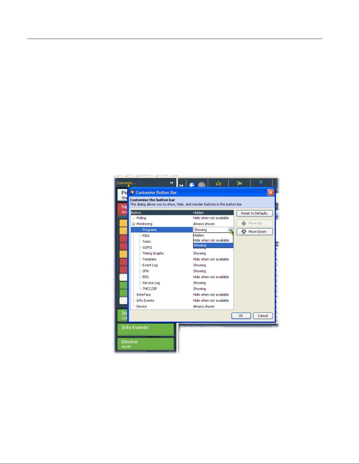
Customizing the Button Bar. To customize the button bar for your monitoring
requirements, select Customize from the top of the button bar or from the button
bar context menu to open the Customize Button Bar dialog box (see Figure 1−4).
The Device and Monitoring buttons are always shown. Other buttons can be
permanently shown, permanently hidden, or automatically hidden when the
function or feature is not available. Select the option from the drop-down list that
is available when the button name is highlighted.
You can change the position of buttons in the Monitoring group by highlighting
the button name and using the Move Up and Move Down buttons.
You can customize the display to show or hide the button bar depending on your
monitoring needs (see page 1−7).
mtm4a_bbar_customize.tif
1−6
Figure 1−4: Customize Button Bar dialog box
Version 00f
MTM400A MPEG Transport Stream Monitor Technical Reference

RUI Overview
Showing / Hiding the Button Bar and the Main Application View. By clicking on the
appropriate button, you can hide the button bar, leaving only the main application window displayed, or you can hide the main application window, leaving
only the button bar displayed.
Hide the button bar
Hide the main application view
Show the button bar / main application view
Main Application View
As shown in Figure 1−1 on page 1−2, the main application view contains the
following display elements:
H Top-level tabs. The top-level tabs provide access to the FlexVuPlus display
and the following Analysis views:
H Programs view
H Tests view
H SI/PSI (Tables) view
H PIDs view
H Packets view
H Interface view (where an interface card is installed)
H Summary tabs. The Summary tabs provide access to the individual analysis
views, which include the tree views and the detail views.
H Tree view. Each analysis view includes a tree view. This is a hierarchical
view of the related analysis information.
H Detail view(s). The detail views vary depending on which node is high-
lighted in the tree view. Detail views include summary views, error logs, and
thumbnail views.
Version 00f
MTM400A MPEG Transport Stream Monitor Technical Reference
1−7
RUI Overview
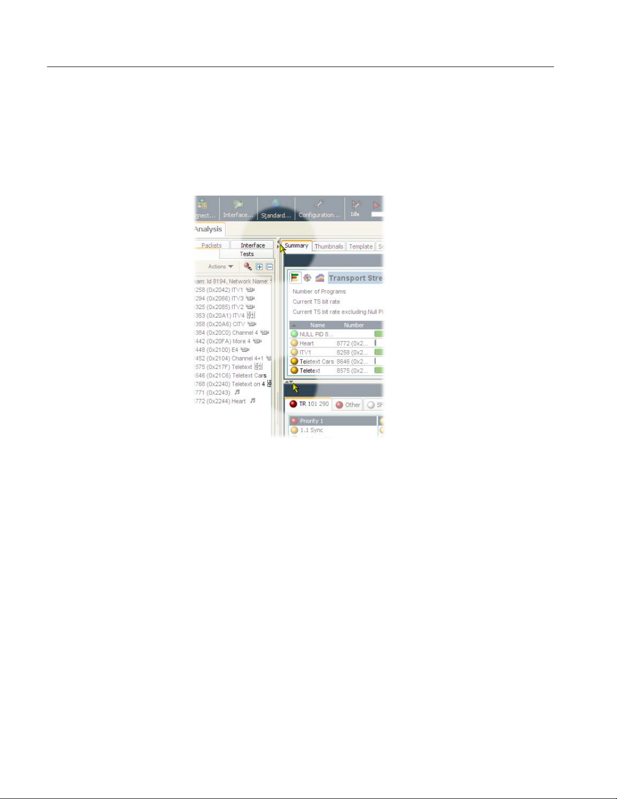
Horizontal and Vertical Panel Slides. Using the horizontal and vertical panel
controls (see Figure 1−5), you can cause a single pane in the main application
window to expand horizontally or vertically. The controls are displayed on the
divider bars that are between views and panels. The RUI window size and panel
boundaries can be dragged in the conventional Windows manner to resize them.
1−8
Figure 1−5: Panel slide controls
Version 00f
MTM400A MPEG Transport Stream Monitor Technical Reference