

Page 1

Programmer Manual
MTM400A
MPEG Transport Stream Monitor
071-2498-00
This document applies to firmware version 3.0
and above.
www.tektronix.com
Page 2

Copyright © Tektronix. All rights reserved. Licensed software products are owned by Tektronix or its subsidiaries or
suppliers, and are protected by national copyright laws and international treaty provisions.
Tektronix products are covered by U.S. and foreign patents, issued and pending. Information in this publication supercedes
that in all previously published material. Specifications and price change privileges reserved.
TEKTRONIX and TEK are registered trademarks of Tektronix, Inc.
Contacting Tektronix
Tektronix, Inc.
14200 SW Karl Braun Drive
P.O. Box 500
Beaverton, OR 97077
USA
For product information, sales, service, and technical support:
H In North America, call 1-800-833-9200.
H Worldwide, visit www.tektronix.com to find contacts in your area.
Page 3

Warranty 2
Tektronix warrants that this product will be free from defects in materials and workmanship for a period of one (1)
year from the date of shipment. If any such product proves defective during this warranty period, Tektronix, at its
option, either will repair the defective product without charge for parts and labor, or will provide a replacement in
exchange for the defective product. Parts, modules and replacement products used by Tektronix for warranty work
may be new or reconditioned to like new performance. All replaced parts, modules and products become the
property of Tektronix.
In order to obtain service under this warranty, Customer must notify Tektronix of the defect before the expiration
of the warranty period and make suitable arrangements for the performance of service. Customer shall be
responsible for packaging and shipping the defective product to the service center designated by Tektronix, with
shipping charges prepaid. Tektronix shall pay for the return of the product to Customer if the shipment is to a
location within the country in which the Tektronix service center is located. Customer shall be responsible for
paying all shipping charges, duties, taxes, and any other charges for products returned to any other locations.
This warranty shall not apply to any defect, failure or damage caused by improper use or improper or inadequate
maintenance and care. Tektronix shall not be obligated to furnish service under this warranty a) to repair damage
resulting from attempts by personnel other than Tektronix representatives to install, repair or service the product;
b) to repair damage resulting from improper use or connection to incompatible equipment; c) to repair any
damage or malfunction caused by the use of non-Tektronix supplies; or d) to service a product that has been
modified or integrated with other products when the effect of such modification or integration increases the time
or difficulty of servicing the product.
THIS WARRANTY IS GIVEN BY TEKTRONIX WITH RESPECT TO THE PRODUCT IN LIEU OF ANY
OTHER WARRANTIES, EXPRESS OR IMPLIED. TEKTRONIX AND ITS VENDORS DISCLAIM ANY
IMPLIED WARRANTIES OF MERCHANTABILITY OR FITNESS FOR A PARTICULAR PURPOSE.
TEKTRONIX’ RESPONSIBILITY TO REPAIR OR REPLACE DEFECTIVE PRODUCTS IS THE SOLE AND
EXCLUSIVE REMEDY PROVIDED TO THE CUSTOMER FOR BREACH OF THIS WARRANTY.
TEKTRONIX AND ITS VENDORS WILL NOT BE LIABLE FOR ANY INDIRECT, SPECIAL, INCIDENTAL,
OR CONSEQUENTIAL DAMAGES IRRESPECTIVE OF WHETHER TEKTRONIX OR THE VENDOR HAS
ADVANCE NOTICE OF THE POSSIBILITY OF SUCH DAMAGES.
Page 4

Warranty 9(b)
Tektronix warrants that the media on which this software product is furnished and the encoding of the programs on
the media will be free from defects in materials and workmanship for a period of three (3) months from the date of
shipment. If any such medium or encoding proves defective during the warranty period, Tektronix will provide a
replacement in exchange for the defective medium. Except as to the media on which this software product is
furnished, this software product is provided “as is” without warranty of any kind, either express or implied.
Tektronix does not warrant that the functions contained in this software product will meet Customer’s
requirements or that the operation of the programs will be uninterrupted or error-free.
In order to obtain service under this warranty, Customer must notify Tektronix of the defect before the expiration
of the warranty period. If Tektronix is unable to provide a replacement that is free from defects in materials and
workmanship within a reasonable time thereafter, Customer may terminate the license for this software product
and return this software product and any associated materials for credit or refund.
THIS WARRANTY IS GIVEN BY TEKTRONIX WITH RESPECT TO THE PRODUCT IN LIEU OF ANY
OTHER WARRANTIES, EXPRESS OR IMPLIED. TEKTRONIX AND ITS VENDORS DISCLAIM ANY
IMPLIED WARRANTIES OF MERCHANTABILITY OR FITNESS FOR A PARTICULAR PURPOSE.
TEKTRONIX’ RESPONSIBILITY TO REPLACE DEFECTIVE MEDIA OR REFUND CUSTOMER’S
PAYMENT IS THE SOLE AND EXCLUSIVE REMEDY PROVIDED TO THE CUSTOMER FOR BREACH OF
THIS WARRANTY. TEKTRONIX AND ITS VENDORS WILL NOT BE LIABLE FOR ANY INDIRECT,
SPECIAL, INCIDENTAL, OR CONSEQUENTIAL DAMAGES IRRESPECTIVE OF WHETHER TEKTRONIX
OR THE VENDOR HAS ADVANCE NOTICE OF THE POSSIBILITY OF SUCH DAMAGES.
Page 5

Table of Contents
Introduction
MTM400A MIB
MIB Group Overview
System Structure
Preface v. . . . . . . . . . . . . . . . . . . . . . . . . . . . . . . . . . . . . . . . . . . . . . . . . . .
Model Numbers vi. . . . . . . . . . . . . . . . . . . . . . . . . . . . . . . . . . . . . . . . . . . . . . . . .
Related Material vi. . . . . . . . . . . . . . . . . . . . . . . . . . . . . . . . . . . . . . . . . . . . . . . . .
SNMP and MIBs 1−1. . . . . . . . . . . . . . . . . . . . . . . . . . . . . . . . . . . . . . . . . . . . . . . . .
MTM400A SNMP Community 1−3. . . . . . . . . . . . . . . . . . . . . . . . . . . . . . . . . . . . .
MTM400A SNMP Traps 1−3. . . . . . . . . . . . . . . . . . . . . . . . . . . . . . . . . . . . . . . . . .
MTM400A Web Server 1−4. . . . . . . . . . . . . . . . . . . . . . . . . . . . . . . . . . . . . . . . . . .
MIB Types 2−1. . . . . . . . . . . . . . . . . . . . . . . . . . . . . . . . . . . . . . . . . . . . . . . . . . . . .
Accessing MIB Objects 2−3. . . . . . . . . . . . . . . . . . . . . . . . . . . . . . . . . . . . . . . . . . .
System Information Group 4−1. . . . . . . . . . . . . . . . . . . . . . . . . . . . . . . . . . . . . . . . .
Box Event Group 4−5. . . . . . . . . . . . . . . . . . . . . . . . . . . . . . . . . . . . . . . . . . . . . . . .
Box Log Group 4−7. . . . . . . . . . . . . . . . . . . . . . . . . . . . . . . . . . . . . . . . . . . . . . . . . .
Network Settings 4−9. . . . . . . . . . . . . . . . . . . . . . . . . . . . . . . . . . . . . . . . . . . . . . . .
License Table 4−10. . . . . . . . . . . . . . . . . . . . . . . . . . . . . . . . . . . . . . . . . . . . . . . . . . .
MPEG Structure
MPEG Interfaces Group 5−1. . . . . . . . . . . . . . . . . . . . . . . . . . . . . . . . . . . . . . . . . . .
MPEG Events Group 5−25. . . . . . . . . . . . . . . . . . . . . . . . . . . . . . . . . . . . . . . . . . . . .
MPEG PIDs Group 5−28. . . . . . . . . . . . . . . . . . . . . . . . . . . . . . . . . . . . . . . . . . . . . . .
MPEG Structure Group 2 5−35. . . . . . . . . . . . . . . . . . . . . . . . . . . . . . . . . . . . . . . . . .
MPEG Log Group 5−39. . . . . . . . . . . . . . . . . . . . . . . . . . . . . . . . . . . . . . . . . . . . . . . .
MPEG Trap Control 5−41. . . . . . . . . . . . . . . . . . . . . . . . . . . . . . . . . . . . . . . . . . . . . .
MPEG Configuration Group 5−43. . . . . . . . . . . . . . . . . . . . . . . . . . . . . . . . . . . . . . .
MPEG Parameters Group 5−45. . . . . . . . . . . . . . . . . . . . . . . . . . . . . . . . . . . . . . . . . .
MPEG Record Group 5−49. . . . . . . . . . . . . . . . . . . . . . . . . . . . . . . . . . . . . . . . . . . . .
Web Server URLs
Configuration 6−1. . . . . . . . . . . . . . . . . . . . . . . . . . . . . . . . . . . . . . . . . . . . . . . . . . .
Status 6−2. . . . . . . . . . . . . . . . . . . . . . . . . . . . . . . . . . . . . . . . . . . . . . . . . . . . . . . . . .
Schedules 6−2. . . . . . . . . . . . . . . . . . . . . . . . . . . . . . . . . . . . . . . . . . . . . . . . . . . . . .
Recording 6−3. . . . . . . . . . . . . . . . . . . . . . . . . . . . . . . . . . . . . . . . . . . . . . . . . . . . . .
Logging 6−3. . . . . . . . . . . . . . . . . . . . . . . . . . . . . . . . . . . . . . . . . . . . . . . . . . . . . . . .
Service Logs 6−4. . . . . . . . . . . . . . . . . . . . . . . . . . . . . . . . . . . . . . . . . . . . . . . . . . . .
TMCC Information 6−5. . . . . . . . . . . . . . . . . . . . . . . . . . . . . . . . . . . . . . . . . . . . . . .
MTM400A MPEG Transport Stream Monitor Programmer Manual
i
Page 6

Table of Contents
Templates 6−6. . . . . . . . . . . . . . . . . . . . . . . . . . . . . . . . . . . . . . . . . . . . . . . . . . . . . .
Licensing 6−7. . . . . . . . . . . . . . . . . . . . . . . . . . . . . . . . . . . . . . . . . . . . . . . . . . . . . .
Debug Information 6−8. . . . . . . . . . . . . . . . . . . . . . . . . . . . . . . . . . . . . . . . . . . . . . .
Controls 6−10. . . . . . . . . . . . . . . . . . . . . . . . . . . . . . . . . . . . . . . . . . . . . . . . . . . . . . . .
Table Information 6−11. . . . . . . . . . . . . . . . . . . . . . . . . . . . . . . . . . . . . . . . . . . . . . . .
PCR/PTS Information 6−12. . . . . . . . . . . . . . . . . . . . . . . . . . . . . . . . . . . . . . . . . . . . .
Repetition Information 6−13. . . . . . . . . . . . . . . . . . . . . . . . . . . . . . . . . . . . . . . . . . . .
RF Card Information 6−15. . . . . . . . . . . . . . . . . . . . . . . . . . . . . . . . . . . . . . . . . . . . .
Thumbnail Data Interface 6−20. . . . . . . . . . . . . . . . . . . . . . . . . . . . . . . . . . . . . . . . . .
Polling Interface 6−23. . . . . . . . . . . . . . . . . . . . . . . . . . . . . . . . . . . . . . . . . . . . . . . . .
ii
MTM400A MPEG Transport Stream Monitor Programmer Manual
Page 7

List of Figures
Table of Contents
Figure 2−1: Time stamp storage 2−2. . . . . . . . . . . . . . . . . . . . . . . . . . . . . .
Figure 3−1: Overall MIB structure 3−1. . . . . . . . . . . . . . . . . . . . . . . . . . .
Figure 3−2: System structure 3−2. . . . . . . . . . . . . . . . . . . . . . . . . . . . . . . .
Figure 3−3: MPEG structure 3−2. . . . . . . . . . . . . . . . . . . . . . . . . . . . . . . .
Figure 3−4: MTM400A structure 3−3. . . . . . . . . . . . . . . . . . . . . . . . . . . . .
Figure 4−1: System structure 4−1. . . . . . . . . . . . . . . . . . . . . . . . . . . . . . . .
Figure 4−2: System information group structure 4−1. . . . . . . . . . . . . . . .
Figure 4−3: Box event group structure 4−5. . . . . . . . . . . . . . . . . . . . . . . .
Figure 4−4: Box log group structure 4−7. . . . . . . . . . . . . . . . . . . . . . . . . .
Figure 5−1: MPEG structure 5−1. . . . . . . . . . . . . . . . . . . . . . . . . . . . . . . .
Figure 5−2: MPEG interfaces group structure 5−1. . . . . . . . . . . . . . . . . .
Figure 5−3: MPEG interfaces table structure 5−2. . . . . . . . . . . . . . . . . . .
Figure 5−4: L-Band information group structure 5−7. . . . . . . . . . . . . . .
Figure 5−5: QAM information group structure 5−12. . . . . . . . . . . . . . . . .
Figure 5−6: MPEG events group structure 5−25. . . . . . . . . . . . . . . . . . . . .
Figure 5−7: MPEG PIDs group structure 5−28. . . . . . . . . . . . . . . . . . . . . .
Figure 5−8: Structure group 2 structure 5−36. . . . . . . . . . . . . . . . . . . . . . .
Figure 5−9: MPEG log group structure 5−39. . . . . . . . . . . . . . . . . . . . . . . .
Figure 5−10: MPEG configuration group 5−43. . . . . . . . . . . . . . . . . . . . . .
Figure 5−11: MPEG parameters group structure 5−45. . . . . . . . . . . . . . . .
MTM400A MPEG Transport Stream Monitor Programmer Manual
iii
Page 8

Table of Contents
iv
MTM400A MPEG Transport Stream Monitor Programmer Manual
Page 9

Preface
This document specifies the MTM400A MPEG Transport Stream Monitor
remote control and status monitoring interfaces available to a Management
application. Two interfaces are provided; SNMP and an HTTP Web-based
interface.
The manual is organized into the following sections:
H Introduction
H MTM400A MIB (Management Information Base)
H MIB Group Overview
H System Structure
H MPEG Structure
H Web Server URLs
The following documents are available on the Tektronix Web site
(www.tektronix.com):
H MTM400A MPEG Transport Stream Monitor Quick Start User Manual
(Tektronix part number: 071-2492-xx)
H MTM400A MPEG Transport Stream Monitor Technical Reference
(Tektronix part number: 071-2495-xx)
These manuals provide operational information for the MTM400.
H MTM400A MPEG Transport Stream Monitor Test Parameter and Configura-
tion File Technical Reference (Tektronix part number: 071-2497-xx)
This manual describes test parameters and configuration file syntax.
The following standards documents are available from the ISO (International
Standards Organization), www.iso.org:
H STD-15 (RFC1157) Simple Network Management Protocol
H STD-16 (RFC1155 and RFC1212)
Structure and Identification of Management Information for TCP/IP-based
Internets
MTM400A MPEG Transport Stream Monitor Programmer Manual
v
Page 10

Preface
Model Numbers
Related Material
This document describes the MIB for both the MTM400A and the MTM400
instruments. The software is common to both instruments and care has been
taken to ensure that all the interfaces remain consistent. So that an MTM400A
returns “MTM400” as a model number through the MIB. This is to ensure that it
would be an exact replacement for the MTM400 in customer systems.
The following URLs access the Web sites for the standards organizations listed
(the URLs listed were valid at the time of writing):
H MPEG−2 standards (International Organization for Standards)
www.iso.org/
H DVB standards (European Technical Standards Institute)
www.etsi.org/
H ATSC standards (Advanced Television Systems Committee)
www.atsc.org/
H ISDB/ARIB standards (Association of Radio Industries and Businesses)
www.arib.or.jp/english/
H SCTE Society of Cable Television Engineers
www.scte.org/
vi
MTM400A MPEG Transport Stream Monitor Programmer Manual
Page 11

Introduction
Page 12

Page 13

Introduction
This document specifies the MTM400A MPEG Transport Stream Monitor
remote control and status monitoring interfaces available to a Management
application. Two interfaces are provided; SNMP and an HTTP Web-based
interface.
NOTE. The MTM400A Programmer Interface MIB file accompanying this
document contains entries not described in the manual. These entries should not
be used.
This document should be read in conjunction with the MTM400A Quick Start
User Manual and Technical Reference. The reader must be thoroughly familiar
with the operation of the MTM400A and have detailed knowledge of SNMP and
HTTP.
Do not use multiple variable binding SET requests. Only single variable binding
SET requests should be used.
SNMP and MIBs
This document specifies the facilities provided by the MTM400A Simple
Network Management Protocol (SNMP) agent, which allows various parameters
within the MTM400A monitor to be viewed and set. This will allow you to
develop management applications that can control the MTM400A instrument
across a network using SNMP.
The MTM400A SNMP agent has been implemented as an extensible agent under
Nucleus, and as such conforms to SNMP v1.
The Simple Network Management Protocol (SNMP) is an Internet standard
protocol for remote management of entities on a network. It is defined in Internet
documents STD-15 (RFC1157) and STD-16 (RFC1155 and RFC1212). STD-15
defines the protocol operations; STD-16 defines the way in which information is
structured under SNMP (SMI - Structure of Management Information).
SNMP defines a way of structuring information in a hierarchy of objects
supporting both single objects and tables of objects, and making the information
available through a network protocol.
Each object can be one of four types, namely:
H Integer. Represents numerical values.
MTM400A MPEG Transport Stream Monitor Programmer Manual
1−1
Page 14

Introduction
H OctetString. Represents byte streams.
H DisplayString. Represents printable strings.
H Object Identifier (OID). References other objects within SNMP.
There are essentially three types of operations that can be performed on each
object:
H Get. Retrieves the value of an object.
H GetNext. Retrieves the value of an object along with the OID of the next
object available.
H Set. Sets the value of an object.
The complete set of objects accessible through an SNMP agent is called the
Management Information Base (MIB). The MIB is a tree structure with MIB
objects at the leaves of the tree. Every branch and leaf of the tree is numbered
according to a scheme ultimately under the administration of either ISO or the
CCITT (or the ITU-T as they are now called). (The root of the tree has three
branches: branch 0 is owned by the CCITT, 1 by ISO and 2 is jointly owned by
ISO and the CCITT.) These organizations have delegated various branches of
this tree to other authorities. Everything of interest to SNMP is under the control
of the IANA (Internet Assigned Numbers Authority), which owns the branch
named:
iso (1).org (3).dod (6).internet (1)
The strings of numbers identifying parts of the MIB tree are called Object
Identifiers (OIDs).
The Internet standard management sub-trees are all under
iso (1).org (3).dod (6).internet (1).mgmt (2).
However the IANA also allocates numbers to other organizations. Companies
can obtain their own sub-trees under
iso (1).org (3).dod (6).internet (1).private (4).enterprises (1).
This entire tree structure is called the MIB. A MIB module is a set of sub-sections of this tree that form some coherent function or set of functions, usually
described in a single document and qualified with some other title, such as
RMON MIB.
NOTE. A MIB module is sometimes referred to as the MIB.
1−2
MTM400A MPEG Transport Stream Monitor Programmer Manual
Page 15

A MIB Module is defined in a text file using ASN.1 (Abstract Syntax Notation
One).
For more detailed explanations of network management using SNMP, you can
refer to The Simple Book: An Introduction to Internet Management (Marshall T.
Rose, Prentice Hall, ISBN 0-13-451659-1).
MTM400A SNMP Community
SNMP provides a simple mechanism for security, there are community strings to
govern read and write to the MIB; these function as passwords.
For the MTM400A, the community string “public” is used for read and write
access. It is possible to add a second community string. However, the “public“
access will still work.
MTM400A SNMP Traps
Introduction
SNMP provides a mechanism for a device to send a notification message to the
management system when an event occurs. This means that the management
system can poll the device less often and so reduce network traffic.
The important point to note here is that it does not mean that the management
system can stop polling the device. Traps are sent using the UDP network
protocol. This mechanism does not guarantee arrival of all packets; a trap
message can be lost.
Trap messages may be lost not only in the UDP transport layer, but inside the
device. The MTM400A takes steps to avoid flooding the network with traps; this
means some traps are discarded when there are a burst of errors in a stream. A
trap should be thought of as a prompt to visit the device to discover status rather
than a mechanism to completely know the status.
To prevent a flood of trap messages on a network, the MTM400A has a
throttling mechanism. A flood of trap messages is to be avoided since this could
hamper the operator’s ability to use the network to understand and contain an
error condition. In the extreme case a flood of trap messages could cause the
management system to fail.
On the MTM400A, a maximum number of trap messages per second is defined.
This is in total, so, if a limit of 10 per second is set, this will yield 5 per second
if two trap consumers are subscribed. Internally, there is a buffer for 100 traps so
a short burst can be accommodated without losing messages. If the buffer
overflows, trap messages are discarded.
The implication of the preceding information is that network bandwidth, or trap
handling capability, is treated as a limited resource. To avoid wasting this
MTM400A MPEG Transport Stream Monitor Programmer Manual
1−3
Page 16

Introduction
resource, steps are taken to ensure that any management system subscribed for
trap messages still requires these messages. So when a management system
subscribes to trap messages, this is only for a few minutes. The management
system must repeatedly subscribe in order to continue to receive trap messages.
This provides protection in the case of a management system exiting improperly.
Some users do not want to repeatedly subscribe. In this situation, the trap
timeout can be set to zero, in which case, subscription is suspended and trap
messages are sent indefinitely.
NOTE. If the trap timeout is set to zero, a central error in a network of
MTM400A instruments may cause every MTM400A to report its full rate of
traps, which can limit the user’s ability to control the network and correct the
error.
MTM400A Web Server
The MTM400A has a Web server interface on HTTP port 80. A number of
URL’s are supported and are used primarily for transferring bulk data, unsuited
to SNMP, to and from the MTM400A.
A full list of supported Web server URLs is given in this manual (see Web Server
URLs section).
1−4
MTM400A MPEG Transport Stream Monitor Programmer Manual
Page 17

MTM400 MIB
Page 18

Page 19

MTM400A MIB
MIB Types
Tektronix has been assigned the following root OID:
iso.org.dod.internet.private.enterprises.128
Under this OID Tektronix can define its own MIB for various products.
The MIB subtree for MTM400A is under the following OID:
iso.org.dod.internet.private.enterprises.tek(128).tvt(5).tvtproducts(1).
The tree is specified in the two ASN.1 text files: ADSYS.MIB defines the
structure of device specific elements and ADMPEG.MIB defines the structure of
the MPEG Interface specific elements.
The supplied MIB includes some items that do not apply to the MTM400A,
because the MIB is common to several products.
The MTM400A MIB defines the following extra MIB types.
EVID
EvState
This type defines events that can occur within the MTM400A. It is essentially a
WORD, where values 0x1xxx represent events that are generated by the
MTM400A instrument such as Clock and Battery errors. Values over and
including 0x2000 represent events that are generated by specific MPEG
Interfaces such as Sync Lock or Continuity errors. The full list of these events
can be found in the MTM400A Test Parameter and Configuration File Technical
Reference (Tektronix part number: 071-2497-xx).
This type represents the state of a given event which can be Green, Yellow or
Red. Green indicates that there is no error, yellow indicates that there has been
an error since this event was last reset, and red indicates that there is a persistent
error.
This is essentially a WORD. Green is defined as 0x1000, yellow as 0x2000 and
red as 0x3xxx, where
that the state is unknown (for example, during the settling time of a test), and
0x4000 means that the event is disabled. Two final values are also possible:
0x5000 is the maintenance state and 0x6000 is N/A (for example, SFN testing
when there is no SFN data).
xxx is the specific error number. A value of 0x0000 means
MTM400A MPEG Transport Stream Monitor Programmer Manual
2−1
Page 20

MTM400 MIB
ÏÏ
ÏÏ
ÏÏ
ÏÏ
AlmValue
Simple Boolean
Log Index
Time Stamp
This specifies which alarms are activated when an event occurs. It is an integer
type and can take combinations of the following values:
0x00000001 = Audible Alarm
0x00000100, 0x00000200, .. , 0x00001000= Relay1, Relay2, .., Relay 5
0x00010000, 0x00020000, .. , 0x00040000= TTL1, TTL2, TTL3
0x00100000, 0x00200000 = Send Trap on; Raise, Clear
This enumerated type is used to represent a Boolean value.
This type represents an integer index into a log.
Time stamps are used in several MIB items to specify the time of events. Each
time stamp is stored as an eight-byte structure, which consists of an 11-bit signed
integer representing the UTC offset and a 53 bit signed integer representing the
UTC time. The UTC offset is the number of minutes that must be added to UTC
time to obtain the local time on the MTM400A instrument. The UTC time is the
number of microseconds since midnight Greenwich Mean Time (GMT) January
1, 1970.
Figure 2−1 shows that the timestamp is actually stored with the UTC offset,
followed by the UTC Time in MSB format. However, the bytes are reversed
when the timestamp is presented as part of an Octet String through SNMP so
that the numbers are in LSB format. Care should be taken with byte 6 because it
contains both the UTC offset and UTC time.
2−2
UTC Offset
11 bits
Stored Format
SNMP Format
MSB LSB
76543210
01234567
LSB
Figure 2−1: Time stamp storage
MTM400A MPEG Transport Stream Monitor Programmer Manual
UTC Time
53 bits
MSB
Page 21

Accessing MIB Objects
MTM400 MIB
This section describes how to access objects within the MTM400A MIB.
SNMP Access
Operations
Single Leaf Objects
Tables
The MTM400A SNMP agent fully supports the standard SNMP GetRequest,
GetNextRequest, and SetRequest PDU operations. This document specifies the
access permissions for each object within the MTM400A MIB using the
following conventions:
H ‘Get’ indicates that the GetRequest and GetNextRequest can be used.
H ‘Set’ indicates that the SetRequest can be used.
Single Leaf Objects are single-value elements whose values can be accessed
using the standard SNMP access operations by appending ‘0’ to the appropriate
OID specified in the MIB. For example, in order to access the program name
within the System Information Group, use the following OID:
‘…adsysProductName.0’.
The MTM400A MIB defines a number of tables. Tables normally contain
objects that can have multiple values, each referenced by appending the required
row number to the OID of the object specified in the MIB. Management
applications typically access values of objects within tables by first performing a
GetNextRequest-PDU on the OID object that will return the OID of the first
value. Subsequent calls to the GetNextRequest operation will obtain the values
for this object within the table. When the operation returns the ‘No Such Name’
error, this indicates that the last value has been reached.
Some tables within the MTM400A MIB are indexed by two or more values, so
accessing object values becomes a little more complex. For example, the Event
State Table is indexed by stream number and event id, so in order to reference a
specific value, the OID should be created by appending the stream number and
the event id to the OID specified for this object in the MIB. Consequently, in
order to access the EventState for an event on a specific stream, use the
following OID:
‘…mivevtEventState.<interface_no>.<eventid>’.
The GetNextRequest-PDU operation will return the OID of the next eventid,
until they have all been exhausted for that stream. At this point it will return the
next interface_no, and the first event_id on that interface (or ‘No Such Error’ if
no more interfaces exist to indicate that the end of the table has been reached).
MTM400A MPEG Transport Stream Monitor Programmer Manual
2−3
Page 22

MTM400 MIB
When a table is defined within the MIB, each table leaf object is represented by
the following OID:
‘…<table_oid>.<table_entry_oid>.<table_leaf_object_oid>’.
The ‘table_entry_oid’s within the MTM400A MIB are always given the value 1,
and are not shown on the structure charts within this document because it would
complicate the diagrams. However, it should be recognized that these must be
included in the OIDs when referencing objects.
2−4
MTM400A MPEG Transport Stream Monitor Programmer Manual
Page 23

MIB Group Overview
Page 24

Page 25
MIB Group Overview
The following sections define the groups of the MIB modules that make up the
MTM400A SNMP interface. There is a split between MPEG-related and
non-MPEG-related objects, and so the groups have been separated into two MIB
modules. The System MIB module contains all non-MPEG-specific groups;
MPEG-specific groups are found in the MPEG MIB module. Figures 3−1 to 3−4
show the overall structure of the MTM400A MIB subtree.
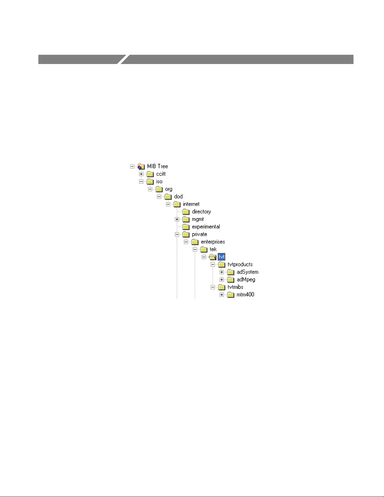
Figure 3−1: Overall MIB structure
MTM400A MPEG Transport Stream Monitor Programmer Manual
3−1
Page 26
MIB Group Overview
The system OID is:
iso(1).org(3).dod(6).internet(1).private(4).enterprises(1).tek(128).tvt(5).
tvtproducts(1).adSystem(16)
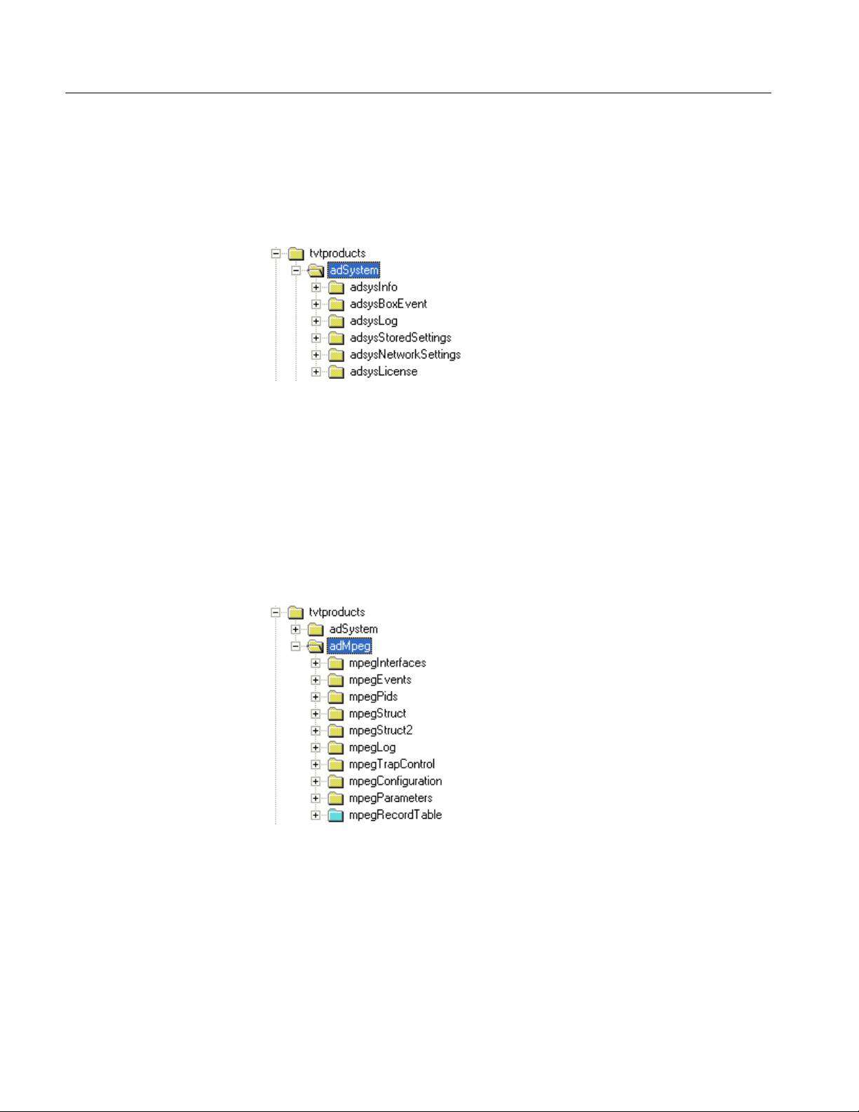
Figure 3−2: System structure
For a complete description of the system structure, refer to the System Structure
section of this manual.
The MPEG OID is:
iso(1).org(3).dod(6).internet(1).private(4).enterprises(1).tek(128).tvt(5).
tvtproducts(1).adMpeg(17)
Figure 3−3: MPEG structure
For a complete description of the MPEG structure, refer to the MPEG Structure
section of this manual (page 5−1).
3−2
MTM400A MPEG Transport Stream Monitor Programmer Manual
Page 27

MIB Group Overview
The MTM400 OID is:
iso(1).org(3).dod(6).internet(1).private(4).enterprises(1).tek(128).tvt(5).tvtmi
bs(2).mtm400(16)
Figure 3−4: MTM400A structure
This area has one entry: product. Reading this entry returns the value
“MTM400”. This section of the MIB is used to identify the product name.
The standard mib-2 sysObjectID leaf
(iso(1).org(3).dod(6).internet(1).mgmt(2).mib−2(1).system(1).sysObjectID(2))
returns the OID of this section (1.3.6.1.4.1.128.5.2.16) for identification.
MTM400A MPEG Transport Stream Monitor Programmer Manual
3−3
Page 28

MIB Group Overview
3−4
MTM400A MPEG Transport Stream Monitor Programmer Manual
Page 29

System Structure
Page 30

Page 31

System Structure
Figure 4−1: System structure
System Information Group
Figure 4−2 shows the structure of the System Information Group, which provides
access to attributes of the most general nature, such as the product name and the
installed software .
Figure 4−2: System information group structure
MTM400A MPEG Transport Stream Monitor Programmer Manual
4−1
Page 32

System Structure
Product Name
DVB Region
For the MTM400 and MTM400A, this is fixed as “MTM400”. This can be used
to positively identify an MTM instrument.
The format of this item is defined as:
Name: adsysProductName
OID: 1.3.6.1.4.1.128.5.1.16.1.1
Full path: iso(1).org(3).dod(6).internet(1).private(4).enterprises(1).
tek(128).tvt(5).tvtproducts(1).adSystem(16).adsysInfo(1).adsysProductNa
me(1)
Module: AD-SYSTEM-MIB
Parent: adsysInfo
Numerical syntax: Octets
Base syntax: OCTET STRING
Composed syntax: OCTET STRING
Status: mandatory
Max access: read-only
Description: A textual name unique to this product type
Obsolete - see MPEG Structure, MPEG Interfaces Table.
Screen Saver Timeout
Software Components
N/A
A list of software components and performance metrics is present on this entity.
The format of this item is defined as:
Variable Type Use Access
aswIndex(1) Integer Table index. Get
aswName(2) Octet string Component name. Get
aswVersion(3) Octet string Component version. Get
4−2
MTM400A MPEG Transport Stream Monitor Programmer Manual
Page 33

System Structure
Global Maintenance Mode
Standard
Config File Index
The format of this item is defined as:
Name: adsysGlobalMaintenanceMode
OID: 1.3.6.1.4.1.128.5.1.16.1.5
Full path: iso(1).org(3).dod(6).internet(1).private(4).enterprises(1).
tek(128).tvt(5).tvtproducts(1).adSystem(16).adsysInfo(1).adsysGlobalMai
ntenanceMode(5)
Module: AD-SYSTEM-MIB
Parent: adsysInfo
Numerical syntax: Integer (32 bit)
Base syntax: INTEGER
Composed syntax: SimpleBoolean
Status: mandatory
Max access: read-write
Description: Setting this variable to true sets the whole box into global maintenance
mode. In this state, processing of events continues, but no alarms are
raised.
Obsolete
N/A
Delete Config File
Download Config File
Box Name
N/A
N/A
This value contains a configurable name for the box.
Name: adsysBoxName
OID: 1.3.6.1.4.1.128.5.1.16.1.11
Full path: iso(1).org(3).dod(6).internet(1).private(4).enterprises(1).
tek(128).tvt(5).tvtproducts(1).adSystem(16).adsysInfo(1).adsysBoxName(
11)
Module: AD-SYSTEM-MIB
Parent: adsysInfo
Numerical syntax: Octets
Base syntax: OCTET STRING
Composed syntax: OCTET STRING
Status: mandatory
Max access: read-write
Description: The name of the box
MTM400A MPEG Transport Stream Monitor Programmer Manual
4−3
Page 34

System Structure
UTC Time
UTC Offset
Reset
The UTC time of the box; that is, the number of seconds since midnight 1st
January 1970.
Variable Type Use Access
adsysUTCTime (12) Integer The UTC time of the box. Get/Set
Number of minutes to add to UTC time to get to local time frame - this may be
negative.
Variable Type Use Access
adsysUTCOffset (13) Integer The UTC offset of the box. Get/Set
Setting this value to a hex value DE5B12A resets the device..
Variable Type Use Access
adsysReset (14) Integer Device reset.
Get has no meaning in this context.
Get/Set
Time Source
SNTP Service
Specifies the system time source.
Variable Type Use Access
adsysTimeSource (15) Integer 0 = RTC (Real Time Clock on the
device).
1 = LTC (Longitudinal Time Code).
2 = SNTP (Simple Network Time
Protocol).
Get/Set
The IP Address of an SNTP server.
Variable Type Use Access
adsysSNTPServer (16) IP Address SNTP server IP address. Get/Set
4−4
MTM400A MPEG Transport Stream Monitor Programmer Manual
Page 35
System Structure
MIB Version
Box Event Group
SNMP interface version.
Variable Type Use Access
adsysMIBVersion(17) Octet string SNMP interface version. Get
The MTM400A may generate several box-specific events. Normally, an event
may be in one of five states:
H ‘Red’ (0x3xxx) indicates that there is currently an error condition.
H ‘Yellow’ (0x2000) indicates that there is currently no error condition, but
that one has occurred since this event was last reset.
H ‘Green’ (0x1000) indicates that there is no error condition.
H ‘Gray’ (0x0000) indicates the state is unknown (or that the link is lost).
H ‘White’ (0x4000) indicates that the event is disabled.
Each event also has an alarm value associated with it, which indicates the type of
alarm that will be triggered (such as audible or relay), if the event goes into error.
The full list of box events is specified in the MTM400A Test Parameter and
Configuration File Technical Reference (Tektronix part number: 071-2497-xx).
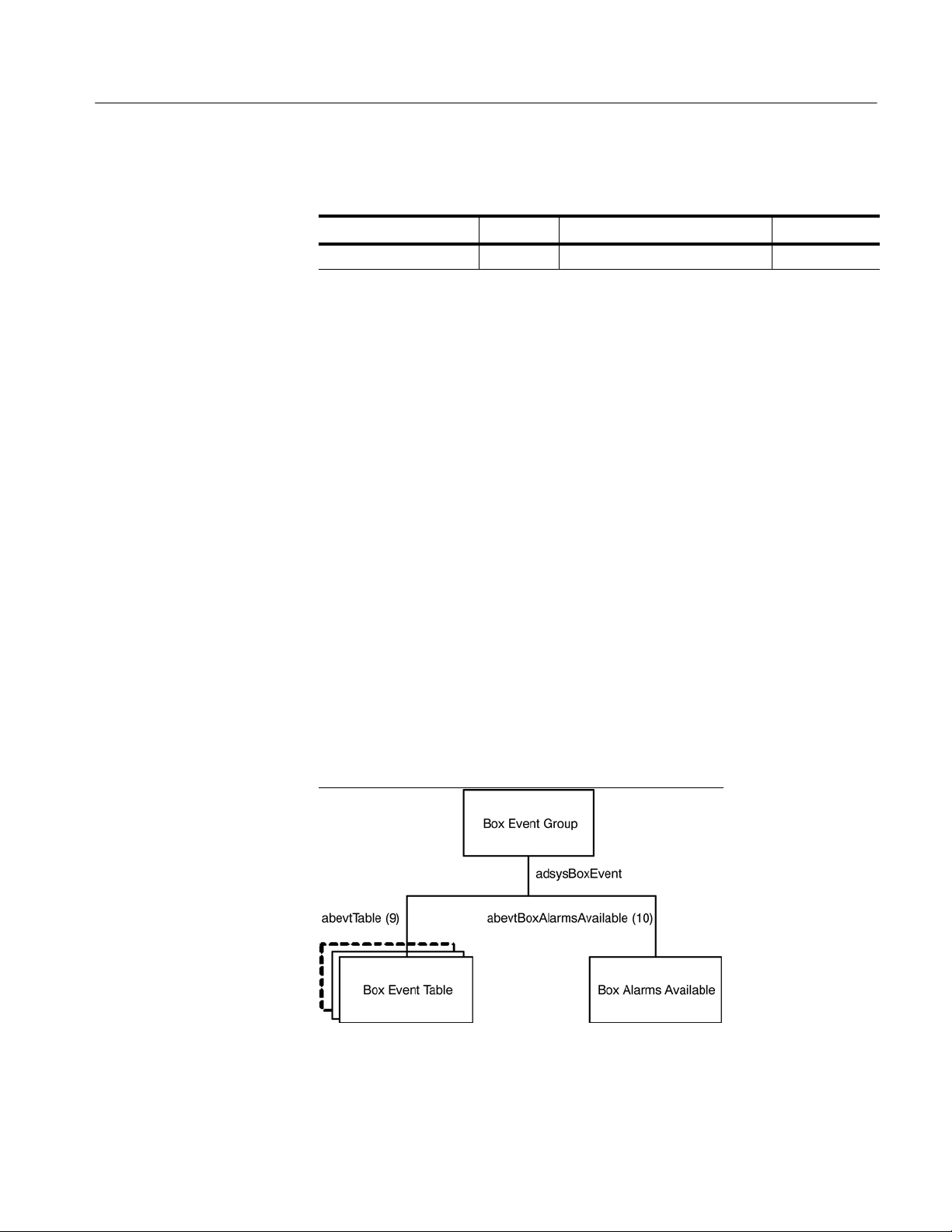
The following diagram shows the structure of the Box Event Group, which
contains information on the states and alarm values for all box events that can be
generated by the MTM400A.
Figure 4−3: Box event group structure
MTM400A MPEG Transport Stream Monitor Programmer Manual
4−5
Page 36

System Structure
The following table describes the objects within the Box Events Group.
Box Events
The Box Alarm table contains the state and alarm value for each box-wide event
as specified in the MTM400A Test Parameter and Configuration File Technical
Reference (Tektronix part number: 071-2497-xx).
Variable Type Use Access
abevtIndex(1) EvId An index identifying the event id as
defined in Appendix A.
abevtEventName(2) Octet string A short name for this event. Get
abevtEventDescription(3) Octet string A brief description of the meaning of
this alarm.
abevtEventState(4) EvState The state of this event. Get/Set
abevtAlarmValue(5) AlmValue The alarms that will be triggered for
this event.
abevtEventEnable(6) Simple
Boolean
Specifies whether the event is
enabled (0 = disabled, 1 = enabled).
N/A
Get
Get/Set
Get/Set
Indexing. The table is indexed by EvId; for example in order to reference the
name of event 0x1000 (4096), use the following OID:
‘…abevtEventName.4096’.
Name and Description. An event name and description are included in this table
so that management applications using this MIB can report all events. (This table
has been designed so that new event types can be added later. A management
application could display all of the event types it knows about in a predetermined
manner, but still be able to display events added after it was written.) These
textual MIB variables would typically be downloaded once when the management application starts, or not at all if you only want to display some particular
fixed set of events.
Unsupported Events. Box events that are not supported for the MTM400A unit
will have an event state of 0x0000.
Event States. Reading the event state returns the current event status as described
for the EvState type (see MTM400A MIB section). Writing any value will reset
the event. The effect of resetting is to change a ‘yellow’ event state to either
‘green’ or ‘unknown’.
4−6
MTM400A MPEG Transport Stream Monitor Programmer Manual
Page 37

Available Box Alarms
Box Log Group
System Structure
Alarm Values. An alarm value specifies which alarms will be triggered when the
corresponding event indicates an error. A value is a combination of those
specified AlmValue (see Box Events, page 4−6), for example, 0x00020401 will
set TTL2, Relay3, and Audible alarms to be triggered.
Variable Type Use Access
abevtBoxAlarmsAvailable(10) AlmValue The result of ‘ORing’ the types
of alarms that can be triggered
for box events. This is determined by the hardware available on the addressed box.
Get
Figure 4−4 shows the structure of the Box Log Group, which provides access to
the box specific log items.
Figure 4−4: Box log group structure
MTM400A MPEG Transport Stream Monitor Programmer Manual
4−7
Page 38

System Structure
The following table describes the single leaf objects within the Box Log Group.
It should be noted that some of these values also apply to the stream logs.
Variable Type Use Access
alogLastEntryTime(1) Time Ticks The value of sysUpTime at which the
most recent entry was added to a
box log or any stream log.
alogFirstEntryIndex(2) Log Index The index of the oldest box log entry. Get
Get
Log Table
alogLastEntryIndex(3) Log Index The index of the most recent box log
entry.
alogMaxRate(6) Integer This sets the maximum number of
entries that will be logged (per
second) for both box and stream
logs. A value of 0 disables logging,
and a value of 10000 specifies that
there is no maximum limit.
alogClear(7) Integer Setting this value clears the box and
stream logs.
Get
Get/Set
Get/Set
The first and last entry indices can be used to access the required elements from
the Log Table, which is shown in the following table.
The log entry table contains information on the event log generated by the
MTM400A, and is defined as:
Variable Type Use Access
alogIndex(1) Log Index Log entry index. N/A
alogText(2) Octet string Contains a coded representation of
the log entry.
Get
4−8
Indexing. The table index is an integer, so it may wrap around if the number of
entries in the log becomes very large. This implies that the element with the
largest index is not necessarily the latest log entry. The index of the last entry can
be obtained from the single leaf element alogLastEntryIndex. In order to obtain
the required log text from the table, use the following OID:
’…alogText.<index>’.
MTM400A MPEG Transport Stream Monitor Programmer Manual
Page 39

System Structure
Log Text Formatting. The alogText will be empty if the index requested is not
valid. This occurs if the management application requests an entry that no longer
exists, for example, if the log was full and the entry was deleted from the end of
the list to make room for new entries. If the log is being filled rapidly, the index
returned from alogFirstEntryIndex is likely to be invalid for a call to alogText.
If alogText is not empty, the format of the octet string is as follows:
Bytes 0..7 : Public timestamp structure.
Bytes 8..9: The ID of the event.
Bytes 10..11 : Extension ID.
Bytes 12..13 : The state of the event.
Bytes 14 - onwards : Text description (UTF8, not NULL terminated).
NOTE. All numeric values are coded with the LSB first.
Network Settings
The network settings table provides information on the device’s network settings.
The information available is defined as:
Variable Type Use Access
aNetIpAddress(1) IP
address
aNetGatewayAddress(2) IP
address
aNetSubnetMask(3) IP
address
aNetCommunityRead(4) Display
string
aNetCommunityWrite(5) Display
string
aNetCommunityTrap(6) Display
string
The IP address of the device. Get/Set
The IP address of the gateway
for the device.
The subnet mask. Get/Set
Alternate SNMP community
string used to read.
Alternate SNMP community
string used to write.
SNMP target community for all
traps.
Get/Set
Get/Set
Get/Set
Get/Set
The read and write community strings in this table are alternates to support
management systems with fixed communities. The default ‘public’ community
will always work.
Changing the network information will have no effect until the MTM400A is
reset.
MTM400A MPEG Transport Stream Monitor Programmer Manual
4−9
Page 40

System Structure
License Table
This field is an octet string containing a variable length bit field enumerating the
licensed capabilities of the unit.
Variable Type Use Access
alicCapabilities(1) Octet
string
The licensed capabilities of the
device.
Get
The current bit definitions are:
0 Structure View 22 Reserved
1 Repetition Graphs 23 Reserved
2 Bitrate Limits 24 Reserved
3 Pid Groups 25 Reserved
4 Templates 26 Reserved
5 Template Tree View 27 DPI
6 Recording 28 Reserved
7 PCR Graphs 29 RF Tests
8 SFN 30 RF Trends
9 Service Log 31 Reserved
10 Pid Variability 32 Reserved
11 Scheduling 33 Reserved
12 Reserved 34 Reserved
13 TMCC 35 Reserved
14 Reserved 36 Reserved
15 Full I/O card 37 Reserved
16 Reduced I/O card 38 Auto Learn
17 Reserved 39 Reserved
18 Reserved 40 Reserved
19 QAM C 41 Wide IP Tests
20 Reserved 42 PES Thumbnails
4−10
21 Reserved 43 JPG Thumbnails
MTM400A MPEG Transport Stream Monitor Programmer Manual
Page 41

System Structure
Each octet has bits numbered from zero for the least significant, to seven for the
most significant. The first octet contains the values 0..7, the second contains
8..15, and so on up to the number of required octets.
MTM400A MPEG Transport Stream Monitor Programmer Manual
4−11
Page 42

System Structure
4−12
MTM400A MPEG Transport Stream Monitor Programmer Manual
Page 43

MPEG Structure
Page 44

Page 45
MPEG Structure
MPEG Interfaces Group
Figure 5−1: MPEG structure
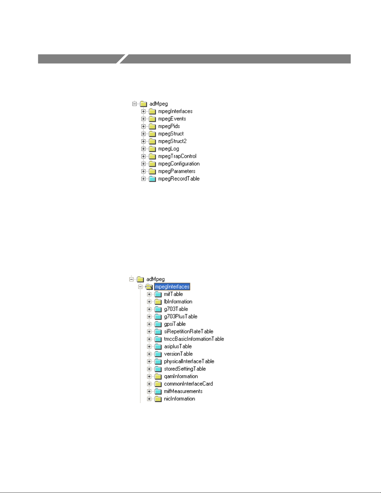
Figure 5−2 shows the structure of the MPEG Interfaces Group, which contains
information on each of the MPEG Interfaces connected to the MTM400A
instrument. The terms ‘Stream’ and ‘Interface’ are used interchangeably.
Figure 5−2: MPEG interfaces group structure
MTM400A MPEG Transport Stream Monitor Programmer Manual
5−1
Page 46
MPEG Structure
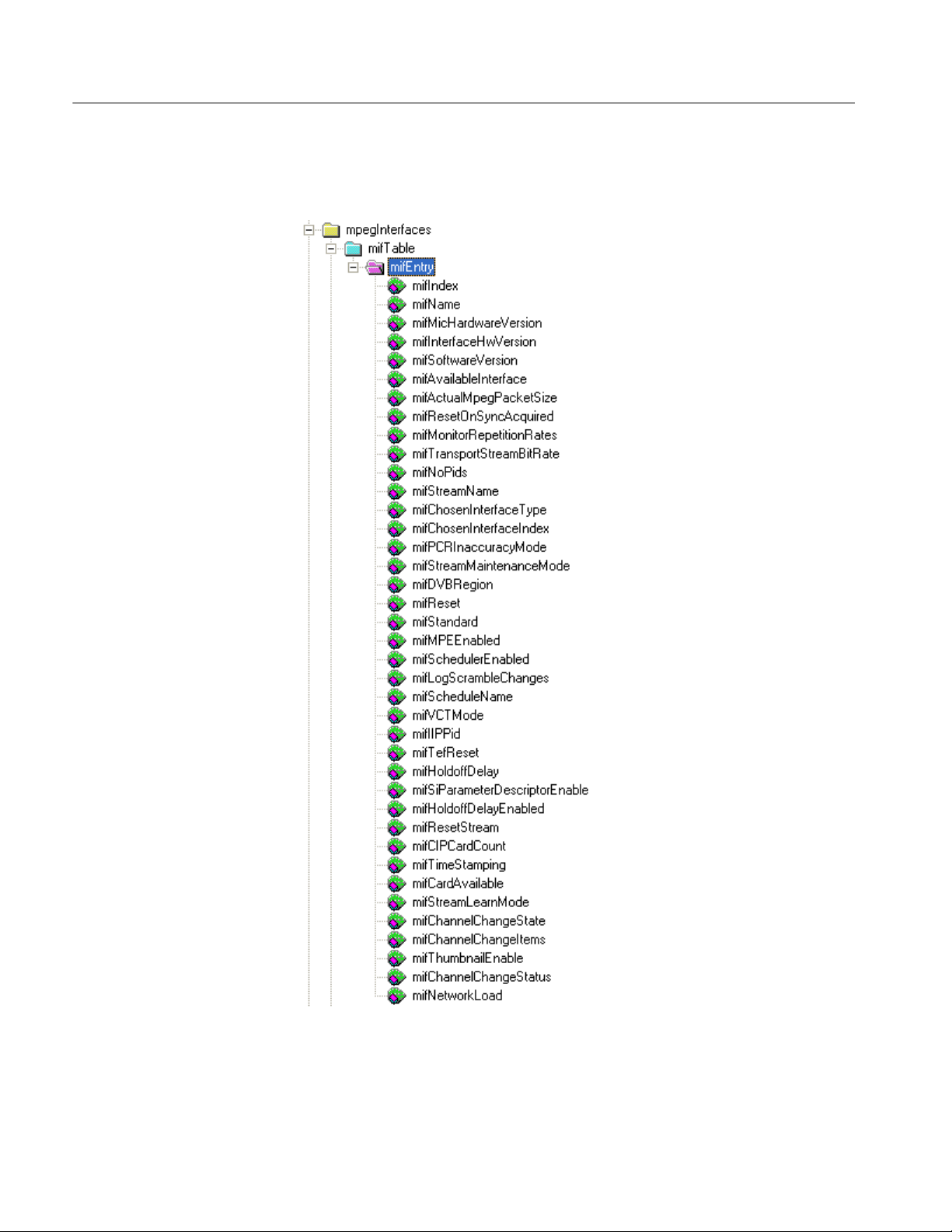
MPEG Interfaces Table
5−2
Figure 5−3: MPEG interfaces table structure
MTM400A MPEG Transport Stream Monitor Programmer Manual
Page 47

MPEG Structure
The MPEG Interfaces table is similar in concept to the Interfaces Group (ifTable)
defined in MIB-II (RFC1213), which provides a list of all network interfaces that
are installed in a device supporting network management. As with the ifTable, it
allows a common network management mechanism to be used to describe and
control MPEG interfaces regardless of the application. Also as with the ifTable,
the indices into the MPEG Interface table can be used as cross references from
other MIB modules, or even as indices for other tables, enabling these to extend
the MPEG Interface table with application-specific information.
The table is defined as:
Variable Type Use Access
mifIndex(1) Integer The MPEG Interface for which these
readings apply. These are used to
identify MPEG interfaces elsewhere
in the MIB.
mifName(2) N/A
mifMicHardwareVersion(3) N/A
N/A
mifInterfaceHwVersion(4) N/A
mifSoftwareVersion (5) N/A
mifAvailableInterface(6) Integer The available interface (see Avail-
able Interface following this table).
mifActualMpegPacketSize(7)
mifResetOnSyncAcquired(8)
mifMonitorRepetitionRates
(9)
mifTransportStreamBitRate(10)
mifNoPids(11) Integer Number of PIDs in the stream with
mifStreamName(12) Octet string Configurable name for the stream. Get/Set
Integer The actual MPEG Packet size
received on this interface. This will
be 0, 188, 204 or 208 where 0
indicates unknown.
N/A
N/A
Integer Transport rate of the stream in bps. Get
non-zero bit rate and those that have
had limits set.
Get
Get
Get
MTM400A MPEG Transport Stream Monitor Programmer Manual
5−3
Page 48

MPEG Structure
Variable AccessUseType
mifChosenInterfaceType(13)
Integer Interface type to use for this stream.
Get/Set
If more than one interface of this
type is available, the first one will be
chosen. To select an interface other
than the first one, use ‘mifChosenInterfaceIndex’ instead.
See ‘physicalInterfaceType’ in the
physical interfaces table for more
information. Any change to this
variable will also affect ‘mifChosenInterfaceIndex’.
mifChosenInterfaceIndex(14)
mifPCRInaccuracyMode(15)
mifStreamMaintenanceMode(16)
mifDVBRegion(17) Integer Specifies the DVB Region of the
Integer Interface index type to use for this
stream. The number selected
matches the ‘physicalInterfaceIndex’
in the physical interfaces table. This
variable must be used in preference
to ‘mifChosenInterfaceType’ to
select an interface other than the
first one of a given type. A change to
this variable may also affect ‘mifChosenInterfaceType’.
N/A
Integer Specifies whether the stream is in
maintenance mode.
0 = off, 1 = on.
stream.
0 = DVB
1 = DTG
2 = Nordic
3 = ISDB
4 = Aus
5 = Reserved
6 = DCII Hybrid
Get/Set
Get/Set
Get/Set
5−4
mifReset(18) Integer Resets the stream parameters to the
factory defaults.
mifStandard(19) Integer Specifies the MPEG Standard for
the stream.
0 = MPEG
1 = DVB
2 = ATSC
3 = ISDB
4 = China
5 = DigiCipher® II
mifMPEEnabled(20) N/A
MTM400A MPEG Transport Stream Monitor Programmer Manual
Get/Set
Get/Set
Page 49

Variable AccessUseType
mifSchedulerEnabled(21) Integer Specifies whether scheduler is
enabled.
0 = disabled
1 = enabled
MPEG Structure
Get/Set
mifLogScrambleChanges(22)
mifScheduleName (23) Octet String The name of the schedule file
mifIIPPid(25) Integer The pid on which the ISDB-T
mifTefReset(26) Integer Setting this to any value resets the
mifHoldoffDelay (27) Integer In ISDB mode there is an option to
mifSiParameterDescripto rEnable (28)
mifHoldoffDelayEnabled
(29)
mifResetStream (30) Integer Setting this to any value restarts the
Integer In ISDB mode some test parameters
Integer In ISDB mode there is an option to
N/A
currently loaded.
Information Packets (IIP) are transmitted.
TEF Count.
prevent alarms in the period following a PAT/PMT change; the length of
the period is set here.
can be taken from the stream;
setting this parameter enables this
mode.
prevent alarms in the period following a PAT/PMT change; setting this
parameter enables this option.
stream and clears all SI and tests.
Get
Get/Set
Get/Set
Get/Set
Get/Set
Get/Set
Get/Set
mifCIPCardCount (31) Integer Returns a count of detected CIP
mifTimeStamping(32) Integer MTS only Get/Set
mifCardAvailable(33) Boolean Indicates presence of interface card Get
mifStreamLearnMode(34) Integer Learn mode Get/Set
mifChannelChangeState(35)
mifChannelChangeItems(36)
mifThumbnailEnable(37) Boolean Global enable (1) or disable (0) of
mifChannelChangeStatus(38)
Integer Shows whether the unit is polling
Integer How many items are in the polling
Integer State of polling, 0=Not polling,
MTM400A MPEG Transport Stream Monitor Programmer Manual
Get
cards.
Get/Set
through configured channels: 0 =
stopped, 1 = running, 2 = paused
Get
script
Get/Set
the thumbnail collection process
Get
1=Acquisition, 2=Testing, 3=About to
poll
5−5
Page 50

MPEG Structure
Indexing. The table is indexed by interface number, for example to reference the
name for interface 1, use the following OID:
‘…mifName.1’.
Available Interface. This field indicates which, if any, of the supported interface
cards are connected to the MTM400A via the serializer port. The interpretation
of the mifAvailableInterface values is as follows:
0x0000 = Unknown
0x0800 = QAM_ANNEX_A
0x2800 = QAM_ANNEX_B
0x1800 = QAM_ANNEX_C
0x4800 = QAM_ANNEX_X (QAM_B unless license bit 19 is set)
0x3800 = LBAND
0x4000 = COFDM, 8PSK, 8VSB, QAMB2 or GbE
0x6800 = SMPTE
0xE000 = ASI
Standard and Region
There are a number of standards; the region field meaning depends on the
standard chosen. For DVB, this field denotes a region; in other cases it is a
specialization.
Standard Region
MPEG (0) Standard (0)
DVB (1) Std (0)
DTG (1)
Nordic (2)
Reserved (3) (was ARIB - see ISDB)
Aus (4)
Reserved (5)
DigiCipher® II Hybrid (6)
ATSC (2) Standard (0)
ISDB (3) ISDB-S (0) (Japanese standard)
ISDB-T (1) (Japanese standard)
ISDB-T (2) (Japanese single segment standard)
Chinese (4) GY/Z 174-2001 (0) (DVB with explicit GB2312 content)
5−6
GB2312 (1) (DVB with implicit GB2312 content)
DigiCipher® II (5) SCTE57 (0)
MTM400A MPEG Transport Stream Monitor Programmer Manual
Page 51

MPEG Structure
LBand Information Group
The following diagram shows the structure of the LBand Information Group,
which contains information on the LBand Settings where appropriate.
Figure 5−4: L-Band information group structure
Default Channels Table. The Default Channels table contains the name of the
stored LBand Settings to use for each interface, and is defined as:
Variable Type Use Access
LbDefaultChannelmifIndex(1) Integer The MPEG interface for which
LbDefaultChannelName(2) Octet
The table is indexed by MPEG Interface, so in order to determine the name of
the stored LBand settings for interface 1, use the following OID:
‘…lbDefaultChannelName.1’.
String
this default channel applies.
The name of the selected
stored settings channel. This is
used to reference the required
entry in the Stored Settings
table on page 5−8.
N/A
Get/Set
MTM400A MPEG Transport Stream Monitor Programmer Manual
5−7
Page 52

MPEG Structure
Stored Settings Table. The Stored Settings table contains the available stored
LBand settings that can be used for each interface, and is defined as:
Variable Type Use Access
LbStoredmifIndex(1) Integer The MPEG interface for which
these stored settings apply.
N/A
lbStoredChannelIndex(2) Integer Index to the stored channel
settings used for this interface.
lbStoredName(3) Octet
string
lbStoredLoFreq(5) Integer Local Oscillator Frequency
ldStoredTrFreq(6) Integer Transponder Frequency (kHz). Get/Set
lbStoredPolarization(7) Integer Polarization (Volts)
lbStoredSymRate(8) Integer Symbol Rate (kSps). Get/Set
lbStoredViterbiRate(9) Integer 0 = 1/2, 1 = 2/3, 2 = 3/4 ,
lbStoredViterbiRateAuto(10) Integer Sets ViterbiRateAuto
lbStoredTone22K(11) Integer Sets 22KHz tone
lbStoredInvertSpectrum(12) Integer Sets invert spectrum
The name given to these stored
settings.
(kHz).
0 = off, 1 = 13(V), 2 = 18(H).
3 = 4/5, 4 = 5/6, 5 = 6/7
0 = off, 1 = on.
0 = off, 1 = on.
0 = off, 1 = on.
N/A
Get
Get/Set
Get/Set
Get/Set
Get/Set
Get/Set
Get/Set
The table is indexed by MPEG Interface followed by Channel Index. The stored
LBand settings are persistent across all interfaces, so the Channel Index is used
to reference which settings should be used from this global list. This has the
consequence that if any of these values are changed on one interface, it will be
changed across all interfaces. As an example, in order to reference the Transponder Frequency for interface 1, channel 2, use the following OID:
5−8
‘….lbStoredTrFreq.1.2’.
MTM400A MPEG Transport Stream Monitor Programmer Manual
Page 53

MPEG Structure
Card Settings Table. The Card Settings table contains the current settings for the
LBand card, and is defined as:
Variable Type Use Access
lbCardmifIndex(1) Integer The MPEG interface for which
these card settings apply.
N/A
lbCardValidSettings(2) Integer Determines whether the LBand
settings for this interface are
valid (if this interface supports
an LBand card: 1 = true, 0 =
false).
lbCardLoFreq(4) Integer Local Oscillator Frequency
(kHz).
ldCardTrFreq(5) Integer Transponder Frequency (kHz). Get/Set
lbCardPolarization(6) Integer Polarization (Volts)
0 = off, 1 = 13(V), 2 = 18(H).
lbCardSymRate(7) Integer Symbol rate (kSps). Get/Set
lbCardViterbiRate(8) Integer 0 = 1/2 , 1 = 2/3, 2 = 3/4,
3 =5/6, 4 = 6/7, 5 = 7/8
lbCardViterbiRateAuto(9) Integer Sets ViterbiRateAuto
0 = off, 1 = on.
lbCardTone22K(10) Integer Sets 22kHz tone
0 = off, 1 = on.
lbCardFrontEndLock(11) Integer Determines whether Front End
Lock is on.
lbCardBER(12) Integer The BER. See below for specif-
ic values.
Get/Set
Get/Set
Get/Set
Get/Set
Get/Set
Get/Set
Get
Get
lbCardInvertSpectrum (13) Integer Sets Invert Spectrum
lbCardMER(14) Integer MER db * 10
lbCardActualBER(15) Integer BER Ratio * 10
lbCardEVM(16) Integer EVM % * 10
lbCardTEFCount(17) Integer TEF count. Get
lbCardSignal(18) Integer Signal Strength % * 10
The table is indexed on MPEG Interface. As an example, in order to reference
the Viterbi Rate for interface 1, use the following OID:
‘….lbCardViterbiRate.1’.
MTM400A MPEG Transport Stream Monitor Programmer Manual
0 = off, 1 = on.
6.
Get/Set
6.
9.
6.
Get
Get
Get
Get
5−9
Page 54

MPEG Structure
The BER values returned have the following meanings:
{1.0e-1, 1},
{9.0e-2, 2},
{8.0e-2, 3},
{7.0e-2, 4},
{6.0e-2, 5},
{5.0e-2, 6},
{4.0e-2, 7},
{3.0e-2, 8},
{2.5e-2, 9},
{1.7e-2, 10},
g703Table. N/A
g703PlusTable. N/A
GPSITable. N/A
{1.3e-2, 11},
{1.0e-2, 12},
{7.0e-3, 13},
{5.5e-3, 14},
{3.0e-3, 15},
{1.5e-3, 16},
{1.0e-3, 17},
{5.5e-4, 18},
{3.0e-4, 19},
{1.5e-4, 20},
{6.0e-5, 21},
{3.0e-5, 22},
{1.0e-5, 23},
{4.0e-6, 24},
{1.0e-6, 25},
{1.0e-7, 26},
{1.0e-8, 27},
{1.0e-9, 28}
SI Repetition Rate Table. N/A
TMCC Basic Information Table. The TMCC Basic Information table contains the
information stored in the first eight bytes of TMCC blocks for each interface. In
order for the MTM400A to process the TMCC information, tmccAcquisition
must be set to 1 for the appropriate stream.
Variable Type Use Access
tmccmifIndex(1) Integer Index N/A
tmccAcquisition(2) Integer Specifies whether to extract
TMCC information.
tmccBufferReset(3) Integer Determines whether the buffer
is reset.
tmccEmergencySignal(4) Integer Determines whether the emer-
gency signal is on.
tmccChangeIndication(5) Integer Determines whether the change
indication is set.
Get/Set
Get
Get
Get
5−10
MTM400A MPEG Transport Stream Monitor Programmer Manual
Page 55

Variable AccessUseType
tmccBeginningOfFrame(6) Integer Determines whether it is the
beginning of a frame.
MPEG Structure
Get
tmccBeginningOfSuperFrame(7)
tmccTransmissionMode1(8) Octet
tmccSlotAllocation1(9) Integer The first slot allocation. Get
tmccTransmissionMode2(10) Octet
tmccSlotAllocation2(11) Integer The second slot allocation. Get
tmccTransmissionMode3(12) Octet
tmccSlotAllocation3(13) Integer The third slot allocation. Get
tmccTransmissionMode4(14) Octet
tmccSlotAllocation4(15) Integer The fourth slot allocation. Get
tmccTransportID(16) Integer The transport ID. Get
tmccRawBytes(17) Octet
Integer Determines whether it is the
beginning of a superframe.
The first transmission mode. Get
string
The second transmission mode. Get
string
The third transmission mode. Get
string
The fourth transmission mode. Get
string
Raw eight bytes of TMCC data. Get
string
ASI Plus Information Table. N/A
Get
Version Table. N/A
Physical Information Table. N/A
Stored Settings Table. N/A
MTM400A MPEG Transport Stream Monitor Programmer Manual
5−11
Page 56

MPEG Structure
QAM Information Group. Figure 5−5 shows the structure of the QAM
Information Group, which contains information on the QAM Settings where
appropriate.
Figure 5−5: QAM information group structure
Status Table. The Status table contains the name of the selected channel settings
and the status of the QAM card. The table is defined as:
Variable Type Use Access
qamStatusmifIndex (1) Integer The MPEG interface for
which this channel applies.
qamCurrentChannelName
(2)
qamFrontEndLock(3) Integer Boolean indicating the
qamSignalStrength (4) Integer The signal strength
Octet
string
The name of the selected
stored channel. This is
used to reference the
required entry in the QAM
Channel Settings table,
see page 5−14.
state of the front end lock
0 - no lock, 1 - in lock.
1 to 5.
N/A
Get/Set
Get
Get
5−12
MTM400A MPEG Transport Stream Monitor Programmer Manual
Page 57

MPEG Structure
Variable AccessUseType
qamBER (5) Integer The BER (0 to 255).
(See BER values below for
specific values.)
qamCardMER(6) Integer MER db * 106. Get
qamCardActualBER(7) Integer BER Ratio * 109. Get
qamCardEVM(8) Integer EVM % * 106. Get
qamCardTEFCount(9) Integer TEF count. Get
qamCardSignal(10) Integer Signal Strength % * 106. Get
Get
The table is indexed by MPEG Interface, so in order to determine the name of
the stored QAM channel settings for interface 1, use the following OID:
‘…qamCurrentChannelName.1’.
The BER values returned have the following meanings:
{1.0e-1, 1},
{9.0e-2, 2},
{8.0e-2, 3},
{7.0e-2, 4},
{6.0e-2, 5},
{5.0e-2, 6},
{4.0e-2, 7},
{3.0e-2, 8},
{2.5e-2, 9},
{1.7e-2, 10},
{1.3e-2, 11},
{1.0e-2, 12},
{7.0e-3, 13},
{5.5e-3, 14},
{3.0e-3, 15},
{1.5e-3, 16},
{1.0e-3, 17},
{5.5e-4, 18},
{3.0e-4, 19},
{1.5e-4, 20},
{6.0e-5, 21},
{3.0e-5, 22},
{1.0e-5, 23},
{4.0e-6, 24},
{1.0e-6, 25},
{1.0e-7, 26},
{1.0e-8, 27},
{1.0e-9, 28}
MTM400A MPEG Transport Stream Monitor Programmer Manual
5−13
Page 58

MPEG Structure
QAM Channel Settings Table. The QAM Channel Settings table contains the
stored QAM settings that can be used for each interface, and is defined as:
Variable Type Use Access
qamChannelSettingsmifIndex
(1)
Integer The MPEG interface for which
these channel settings apply.
N/A
qamChannelIndex (2) Integer Index to the stored channel
settings used for this interface.
qamChannelName (3) Octet
string
qamChannelRxFreq (4) Integer The rx frequency of the channel
qamChannelSymRate (5) Integer The symbol rate of the channel. Get/Set
qamChannel2LoFreq (6) Integer The 2nd Local Oscillator fre-
qamChannelConstellation (7) Integer The constellation (trellis pat-
qamChannelInversion (8) Integer Specifies inversion for the
qamChannelVControl (9) Integer Specifies V Control for the
qamChannelUncorrectable
PacketMode(10)
Integer Specifies the uncorrectable
The name given to these channel settings.
in Hz.
quency of the channel in Hz.
ters) of the channel. The MIB
value is mapped to the constellation as follows:
0 = 4, 1 = 16, 2 = 64, 3 = 256.
channel.
0= not inverted,
1= inverted.
channel.
0 = off, 1 = on.
packet mode. The values have
the following meanings:
N/A
Get
Get/Set
Get/Set
Get/Set
Get/Set
Get/Set
Get/Set
5−14
QamChannelLockConfidence
(11)
QamChannelCorrection
Confidence (12)
qamChannelCarrierReceiverLoopBandwidth(13)
MTM400A MPEG Transport Stream Monitor Programmer Manual
0 = Do not filter bad packets,
1 = Filter bad packets,
2 = Do not send uncorrupted
event status messages,
3 = Send uncorrupted event
status messages.
Integer Reserved. Get/Set
Integer Reserved. Get/Set
Integer 0 = Normal, 1 = Wide. Get/Set
Page 59

MPEG Structure
Variable AccessUseType
qamChannelCarrier
AcquisitionRange(14)
qamChannelTroubleShoot(15) Integer 0 = off, 1 = on. Get/Set
Integer 0 = Normal, 1 = Wide. Get/Set
The table is indexed by the MPEG Interface followed by the Channel Index. The
QAM channel settings are persistent across all interfaces, so the Channel Index is
used to reference which settings should be used from this global list. This has the
consequence that if any of these values are changed on one interface, it will be
changed across all interfaces.
Common Interface Cards
This group is used to control the common interface (CIP) cards, the CIP platform
carries a number of demodulators so the settings change according to card type.
Card Selection Table. This table allows the required Common Interface Card to be
selected. It contains the following elements.
Variable Type Use Access
MifIndex (0) Table
index
currentCard (1) Integer The index of the required card,
corresponding to the CardNumber in the configuration file and
the CardDetails HTTP query.
N/A
N/A
MTM400A MPEG Transport Stream Monitor Programmer Manual
Get this value to determine the
current card selected.
Set this value to change the
card.
5−15
Page 60

MPEG Structure
Control Table
Input Settings Table
This table allows a card to be reset, and the input to be selected, and contains the
following elements:
Variable Type Use Access
MifIndex (0) Table
index
cardIndex Table
index
resetCard Integer Setting this to any value resets
the card.
currentInput Integer The index of the required input.
Get this value to determine the
current input selected. Set this
value to change the input.
N/A
N/A
Set
Get/Set
This table allows the settings to be applied to an input of the card, and will
contain the following elements:
Variable Type Use Access
MifIndex (0) Table index N/A
cardIndex Table index N/A
inputIndex Table index N/A
inputSettingsName Octet String The name of the settings
applied to the input and the
configuration file. Get this
value to determine the name
of the setting currently being
used. Set this value to change
the settings used.
Get/Set
5−16
MTM400A MPEG Transport Stream Monitor Programmer Manual
Page 61

MPEG Structure
Input Settings Control
Table
This table allows settings to be added and deleted, and contains the following
elements.
Variable Type Use Access
MifIndex (0) Table
index
cardIndex Table
index
inputIndex Table
index
addSettings Octet
String
deleteSetting Octet
String
Set this value to add settings
with the specified name to the
list of settings for the input.
Set this value to delete the
settings with the specified
name from the list of settings
for the input. This operation will
fail if the settings specified are
currently set as the inputSettingsName in the Input Settings
Table.
N/A
N/A
N/A
Set
Set
Input Settings Description
Table
This table contains the descriptions of the settings that can be applied to the
input of a card, and contains the following elements.
Variable Type Use Access
MifIndex (0) Table index N/A
cardIndex Table index N/A
inputIndex Table index N/A
settingsIndex Table index N/A
settingsName Octet String The name of the settings for
the settings index. Get this
value to determine the current
name of the settings. Set this
value to change the name of
the settings - this will fail if the
settings are currently being
used.
Get/Set
MTM400A MPEG Transport Stream Monitor Programmer Manual
5−17
Page 62

MPEG Structure
Parameters Table
Gating Value Table
This contains the parameter values for the input of a card, and consists of the
following elements
Variable Type Use Access
MifIndex (0) Table index N/A
cardIndex Table index N/A
inputIndex Table index N/A
settingsIndex Table index N/A
parameterIndex Table index N/A
parameterValue Octet String The value of the parameter.
Get this value to determine the
current value. Set this value to
change the value.
Get/Set
This contains the gating value for the input of a card, and consists of the
following elements:
Variable Type Use Access
MifIndex (0) Table index N/A
cardIndex Table index N/A
inputIndex Table index N/A
settingsIndex Table index N/A
gatingValue Integer The gating value for the input.
0 = off,
1 = on,
2 = auto.
Get this value to determine the
current value.
Set this value to change the
value.
Get/Set
5−18
MTM400A MPEG Transport Stream Monitor Programmer Manual
Page 63

MPEG Structure
Measurements
This section returns the metrics from CIP cards. The cards vary, so not all
measurements are appropriate to all cards.
The following metrics apply to various interface cards, see the section on
retrieving the card details to determine which applies to which.
Index
Name: rfmIndex
OID: 1.3.6.1.4.1.128.5.1.17.1.14.1.1
Full path: iso(1).org(3).dod(6).internet(1).private(4).enterprises(1).
tek(128).tvt(5).tvtproducts(1).adMpeg(17).mpegInterfaces(1).
mifMeasurements(14).mifMetric(1).rfmIndex(1)
Module: AD-MPEG-MIB
Parent: mifMetric
Numerical syntax: Integer (32 bit)
Max access: read-only
Description: A unique value identifying a particular MPEG interface metric. The index
for this table.
MTM400A MPEG Transport Stream Monitor Programmer Manual
5−19
Page 64

MPEG Structure
Lock
Name: rfmLock
OID: 1.3.6.1.4.1.128.5.1.17.1.14.1.2
Full path: iso(1).org(3).dod(6).internet(1).private(4).enterprises(1).
tek(128).tvt(5).tvtproducts(1).adMpeg(17).mpegInterfaces(1).
mifMeasurements(14).mifMetric(1).rfmLock(2)
Module: AD-MPEG-MIB
Parent: mifMetric
Numerical syntax: Integer (32 bit)
Max access: read-only
Description: Lock status of the interface, 0=unlocked 1=locked
Power
Name: rfmPower
OID: 1.3.6.1.4.1.128.5.1.17.1.14.1.3
Full path: iso(1).org(3).dod(6).internet(1).private(4).enterprises(1).
tek(128).tvt(5).tvtproducts(1).adMpeg(17).mpegInterfaces(1).
mifMeasurements(14).mifMetric(1).rfmPower(3)
Module: AD-MPEG-MIB
Parent: mifMetric
Numerical syntax: Integer (32 bit)
Max access: read-only
Description: Input power in dBm * 100
5−20
AGC
Name: rfmAGC
OID: 1.3.6.1.4.1.128.5.1.17.1.14.1.4
Full path: iso(1).org(3).dod(6).internet(1).private(4).enterprises(1).
tek(128).tvt(5).tvtproducts(1).adMpeg(17).mpegInterfaces(1).
mifMeasurements(14).mifMetric(1).rfmAGC(4)
Module: AD-MPEG-MIB
Parent: mifMetric
Numerical syntax: Integer (32 bit)
Max access: read-only
Description: AGC in % * 100
MTM400A MPEG Transport Stream Monitor Programmer Manual
Page 65

SNR
Name: rfmSNR
OID: 1.3.6.1.4.1.128.5.1.17.1.14.1.5
Full path: iso(1).org(3).dod(6).internet(1).private(4).enterprises(1).
tek(128).tvt(5).tvtproducts(1).adMpeg(17).mpegInterfaces(1).
mifMeasurements(14).mifMetric(1).rfmSNR(5)
Module: AD-MPEG-MIB
Parent: mifMetric
Numerical syntax: Integer (32 bit)
Max access: read-only
Description: SNR in dBm * 100
BER Pre RS error correction
Name: rfmBERPRERS
OID: 1.3.6.1.4.1.128.5.1.17.1.14.1.6
Full path: iso(1).org(3).dod(6).internet(1).private(4).enterprises(1).
tek(128).tvt(5).tvtproducts(1).adMpeg(17).mpegInterfaces(1).
mifMeasurements(14).mifMetric(1).rfmBERPRERS(6)
Module: AD-MPEG-MIB
Parent: mifMetric
Numerical syntax: Integer (32 bit)
Max access: read-only
Description: BER pre reed-solomon correction * 1e9
MPEG Structure
BER Pre Viterbi correction
Name: rfmBERPREVIT
OID: 1.3.6.1.4.1.128.5.1.17.1.14.1.7
Full path: iso(1).org(3).dod(6).internet(1).private(4).enterprises(1).
tek(128).tvt(5).tvtproducts(1).adMpeg(17).mpegInterfaces(1).mifMeasure
ments(14).mifMetric(1).rfmBERPREVIT(7)
Module: AD-MPEG-MIB
Parent: mifMetric
Numerical syntax: Integer (32 bit)
Max access: read-only
Description: BER pre viterbi error correction * 1e9
MTM400A MPEG Transport Stream Monitor Programmer Manual
5−21
Page 66

MPEG Structure
BER Post RS error correction
Name: rfmBERPOSTRS
OID: 1.3.6.1.4.1.128.5.1.17.1.14.1.8
Full path: iso(1).org(3).dod(6).internet(1).private(4).enterprises(1).
tek(128).tvt(5).tvtproducts(1).adMpeg(17).mpegInterfaces(1).
mifMeasurements(14).mifMetric(1).rfmBERPOSTRS(8)
Module: AD-MPEG-MIB
Parent: mifMetric
Numerical syntax: Integer (32 bit)
Max access: read-only
Description: BER post reed-solomon correction * 1e9
CNR
Name: rfmCNR
OID: 1.3.6.1.4.1.128.5.1.17.1.14.1.9
Full path: iso(1).org(3).dod(6).internet(1).private(4).enterprises(1).
tek(128).tvt(5).tvtproducts(1).adMpeg(17).mpegInterfaces(1).
mifMeasurements(14).mifMetric(1).rfmCNR(9)
Module: AD-MPEG-MIB
Parent: mifMetric
Numerical syntax: Integer (32 bit)
Max access: read-only
Description: CNR in dBm * 100
5−22
Carrier Offset
Name: rfmCAROFS
OID: 1.3.6.1.4.1.128.5.1.17.1.14.1.10
Full path: iso(1).org(3).dod(6).internet(1).private(4).enterprises(1).
tek(128).tvt(5).tvtproducts(1).adMpeg(17).mpegInterfaces(1).
mifMeasurements(14).mifMetric(1).rfmCAROFS(10)
Module: AD-MPEG-MIB
Parent: mifMetric
Numerical syntax: Integer (32 bit)
Max access: read-only
Description: Carrier offset in Hz
MTM400A MPEG Transport Stream Monitor Programmer Manual
Page 67

MER
Name: rfmMER
OID: 1.3.6.1.4.1.128.5.1.17.1.14.1.11
Full path: iso(1).org(3).dod(6).internet(1).private(4).enterprises(1).
tek(128).tvt(5).tvtproducts(1).adMpeg(17).mpegInterfaces(1).
mifMeasurements(14).mifMetric(1).rfmMER(1 1)
Module: AD-MPEG-MIB
Parent: mifMetric
Numerical syntax: Integer (32 bit)
Max access: read-only
Description: MER in dBm * 100
EVM
Name: rfmEVM
OID: 1.3.6.1.4.1.128.5.1.17.1.14.1.12
Full path: iso(1).org(3).dod(6).internet(1).private(4).enterprises(1).
tek(128).tvt(5).tvtproducts(1).adMpeg(17).mpegInterfaces(1).
mifMeasurements(14).mifMetric(1).rfmEVM(12)
Module: AD-MPEG-MIB
Parent: mifMetric
Numerical syntax: Integer (32 bit)
Max access: read-only
Description: EVM in % * 100
MPEG Structure
The following items are restricted to the Gbe interface card.
Corrupted Packer Rate (CPR)
Name: rfmCPR
OID: 1.3.6.1.4.1.128.5.1.17.1.14.1.13
Full path: iso(1).org(3).dod(6).internet(1).private(4).enterprises(1).
tek(128).tvt(5).tvtproducts(1).adMpeg(17).mpegInterfaces(1).
mifMeasurements(14).mifMetric(1).rfmCPR(13)
Module: AD-MPEG-MIB
Parent: mifMetric
Numerical syntax: Integer (32 bit)
Max access: read-only
Description: Corrupted packets per second
MTM400A MPEG Transport Stream Monitor Programmer Manual
5−23
Page 68

MPEG Structure
Dropped Packet Rate (DPR)
Name: rfmDPR
OID: 1.3.6.1.4.1.128.5.1.17.1.14.1.14
Full path: iso(1).org(3).dod(6).internet(1).private(4).enterprises(1).
tek(128).tvt(5).tvtproducts(1).adMpeg(17).mpegInterfaces(1).
mifMeasurements(14).mifMetric(1).rfmDPR(14)
Module: AD-MPEG-MIB
Parent: mifMetric
Numerical syntax: Integer (32 bit)
Max access: read-only
Description: Dropped packets per second
Packet Interarrival Time (PIT)
Name: rfmPIT
OID: 1.3.6.1.4.1.128.5.1.17.1.14.1.15
Full path: iso(1).org(3).dod(6).internet(1).private(4).enterprises(1).
tek(128).tvt(5).tvtproducts(1).adMpeg(17).mpegInterfaces(1).
mifMeasurements(14).mifMetric(1).rfmPIT(15)
Module: AD-MPEG-MIB
Parent: mifMetric
Numerical syntax: Integer (32 bit)
Max access: read-only
Description: Inter packet interval time
5−24
Out of Order Packet Rate (OOO)
Name: rfmOOO
OID: 1.3.6.1.4.1.128.5.1.17.1.14.1.16
Full path: iso(1).org(3).dod(6).internet(1).private(4).enterprises(1).
tek(128).tvt(5).tvtproducts(1).adMpeg(17).mpegInterfaces(1).
mifMeasurements(14).mifMetric(1).rfmOOO(16)
Module: AD-MPEG-MIB
Parent: mifMetric
Numerical syntax: Integer (32 bit)
Max access: read-only
Description: Out of order packets per second
MTM400A MPEG Transport Stream Monitor Programmer Manual
Page 69
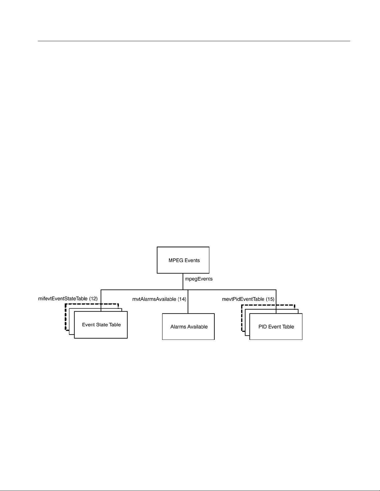
MPEG Events Group
MPEG Structure
The MTM400A may generate several events for each MPEG interface. Normally, an event may be in one of five states:
H ‘Red’ (0x3xxx) indicates that there is currently an error condition.
H ‘Yellow’ (0x2000) indicates that there is currently no error condition, but
that one has occurred since this event was last reset.
H ‘Green’ (0x1000) indicates that there is no error condition.
H ‘Gray’ (0x0000) indicates the state is unknown (or link lost).
H ‘White’ (0x4000) indicates that the event is disabled.
Each event also has an alarm value associated with it, which indicates the type of
alarm that will be triggered (for example, audible or relay), if an error occurs.
The full list of box events is specified in the MTM400A Test Parameters and
Configuration File Technical Reference (Tektronix part number: 071-2497-xx).
Figure 5−6 shows the structure of the MPEG Events Group, which contains
information on the states and alarm values of events on each MPEG Interface.
Figure 5−6: MPEG events group structure
MTM400A MPEG Transport Stream Monitor Programmer Manual
5−25
Page 70

MPEG Structure
Event State Table
The Event State table contains the state of each MPEG Interface event on every
interface, and is defined as:
Variable Type Use Access
mifevtMifIndex (1) Integer The MPEG interface for which
these events apply.
mifevtEventIndex (2) EvId An index uniquely identifying
the event.
mifevtEventName (3) Octet
String
mifevtEventDescription (4) Octet
String
mifevtEventState (5) EvState The state of this event. Writing
mifevtAlarmValue (6) AlmValue The alarms that will be trig-
mifevtEventEnable (7) Simple
Boolean
A short textual title for this
event.
A brief description of this event. Get
any value will reset the event.
The effect of resetting is to
change a ‘yellow’ event state to
either ‘green’ or ‘unknown’.
gered for this event.
Specifies whether this event is
enabled (0 = disabled, 1 =
enabled).
N/A
N/A
Get
Get/Set
Get/Set
Get/Set
mifevtEventExtendedInfo(8) Octet
String
mifevtEventFailureCount(9) Integer Count of failures since reset.
N/A for MTM400A Get
Get
For the MTM400A only: Continuity count error [0x3014]
counter is valid.
Indexing. The table is indexed by MPEG Interface followed by EvId. As an
example, in order to reference the alarm value of event 0x2000 (8192) on
interface 1, use the following OID ‘…mifevtAlarmValue.1.8192’.
Unsupported Events. Events that are not supported on an interface will have an
event state of 0x0000.
Setting Event States. Setting an event that is in the ‘Yellow’ (0x2000), to any
value, resets the event. Setting an event with a ‘Red’ state has no effect, because
this indicates that there is a persistent error.
Setting Alarm Values. An alarm value specifies which alarms will be triggered
when an error occurs in the corresponding event. The value is a combination of
those specified in AlmValue, (for example, 0x00020401 will set TTL2, Relay3,
and Audible alarms to be triggered).
5−26
MTM400A MPEG Transport Stream Monitor Programmer Manual
Page 71

Alarms Available
MPEG Structure
Variable Type Use Access
mevtAlarmsAvailable (14) AlmValue Indicates the types of alarms
that can be triggered for stream
events.
Get
The value returned is a bitfield that shows which alarm action can be enabled/
disabled.
Buzzer = 0x00000001
Recorder = 0x00000020
Relay1 = 0x00000100
Relay2 = 0x00000200
Relay3 = 0x00000400
Relay4 = 0x00000800
Relay5 = 0x00001000
TTL1 = 0x00010000
TTL2 = 0x00020000
TTL3 = 0x00040000
TrapRaise = 0x00100000
TrapClear = 0x00200000
Logging = 0x01000000
PID Event Table
The PID Event table contains a table of MPEG PID specific events on every
interface, and is defined as:
Variable Type Use Access
mevtPidMifIndex (1) Integer The MPEG interface for which
mevtPidEventIndex (2) Evid A unique index identifying a
mevtPidPidIndex (3) Integer The PID number + 1. N/A
MTM400A MPEG Transport Stream Monitor Programmer Manual
N/A
these events apply.
N/A
particular type of PID event.
The values for this index are
prescribed, and can be found
in Appendix A of the MIB
Specification.
5−27
Page 72

MPEG Structure
Variable AccessUseType
mevtPidEventState (4) Evstate Reading this returns the cur-
rent event status for the PID
as described for the EvState
type. Writing any value will
reset the event. The effect of
resetting is to change a ‘yellow’ event state to either
‘green’ or ‘unknown’.
Get/Set
MPEG PIDs Group
mevtPidEventEnable (5) Simple
Boolean
If a per PID event is disabled,
the EvState will always be
reported as ‘disabled’, no
alarms will be generated for
the event and the system does
not need to perform any processing associated with the
event.
Get/Set
Figure 5−7 shows the structure of the PIDs Group, which contains PID, PID
Group and Program limit and rate information:
Figure 5−7: MPEG PIDs group structure
5−28
MTM400A MPEG Transport Stream Monitor Programmer Manual
Page 73

MPEG Structure
PID Status Table
The PID Status table contains PID and Program status information for each
interface, and is defined as:
Variable Type Use Access
pidstMifIndex (1) Integer MPEG interface for which these
elements apply.
pidstClearLimits (2) Integer Setting this clears all the PID
rate limits for this interface.
Reading this value has no meaning.
progstClearLimits (3) Integer As above, but for programs. Get/Set
pidstResetRates (4) Integer Setting this resets all PID mini-
mum and maximum rate measurements for this interface.
Reading this value has no meaning.
progstResetRates (5) Integer As above, but for programs. Get/Set
pidgroupstClearLimits (10) Integer Setting this clears all the PID
group rate limits for this interface.
Reading this value has no meaning.
N/A
Get/Set
Get/Set
Get/Set
pidgroupstResetRates (11) Integer Writing any value to this object
will reset the currently latched
minimum and maximum bit rates
for all PID groups. Reading this
value has no meaning.
pidgroupstNewPidGroupIndex
(12)
pidgroupstDeletePidGroupIndex
(13)
Integer Reading this will create a new
pid group on the MTM400A
instrument. The value returned is
the group index. This is used to
index this group in the pidGroupTable and pidGroupPidsTable.
Integer Writing a value will delete the
group with the index specified by
the value set.
Get/Set
Set
Get/Set
The table is indexed by MPEG Interface. As an example, in order to reference
pidsResetRates for interface 1, use the following OID:
‘…pidstResetRates.1’.
MTM400A MPEG Transport Stream Monitor Programmer Manual
5−29
Page 74

MPEG Structure
PID Table
The PID table contains information for each PID on each interface, and is
defined as:
Variable Type Use Access
pidsMifIndex (1) Integer The MPEG interface for which
these readings apply.
pidsPidIndex (2) Integer The PID index - this is the PID
number + 1 to avoid a 0 index.
pidsRate (3) Integer The most recently measured
rate for this PID.
pidsMinRate (4) Integer The minimum rate latched for
this PID since last reset.
pidsMaxRate (5) Integer The maximum rate latched for
this PID since last reset.
pidsMinLimit (6) Integer The minimum limit for this PID. Get/Set
pidsMaxLimit (7) Integer The maximum limit for this PID. Get/Set
pidsState (8) Evstate The state of this PID. Get/Set
pidsScrambled (11) Simple
boolean
pidsUnreferenced (13) Simple
boolean
0 = PID not scrambled, 1 = PID
scrambled.
Indicates whether the PID is
un-referenced. 1 = un-referenced, 0 = referenced.
N/A
N/A
Get
Get
Get
Get
Get
pidsForceListPresence (15) Simple
boolean
pidsVariability (16) Octet
string
pidsISDBTLayer (18) Integer Indicates which ISDB-T layer
Specifies whether the PID must
exist in this list, event if it does
not appear in the transport
stream. 0 = PID not present, 1
= PID present.
Textual representation of variability (floating point number).
the PID is transmitted on. (1=A,
2=B, 3=C)
Get/Set
Get
Get
H Indexing. The table is indexed by the MPEG Interface, followed by the PID
Index. As an index of 0 is not allowed in SNMP tables, the PID Index is
actually PID+1. Therefore, in order to reference the required PID item, for
example pidsMinLimit, use the following OID:
‘…pidsMinLimit.<interface>.<pid+1>’.
H Reading PID Information. The list of PIDs for which readings are available
can change fairly rapidly, so the management application must be notified
5−30
MTM400A MPEG Transport Stream Monitor Programmer Manual
Page 75

MPEG Structure
that subsequent requests for PID elements may result in values for a different
set of PIDs. Consequently, if a client application requests all of the pidsMinRates followed by pidsMaxRates, it is not guaranteed that the values
obtained will be for exactly the same set of PIDs. Therefore, in order to force
the agent to include a PID in its list, the management application should set
the corresponding Min and Max limits.
H PID Limits. By default, the limits for each PID are not defined; this is
represented by the pidsMinLimit and pidsMaxLimit values being set to 0
and -1 respectively. When setting a limit, the management application must
ensure that the value of pidsMaxLimit is always greater than pidsMinLimit,
otherwise the new setting will not be accepted by the MTM400A. The new
and current values of pidsMinLimit and pidsMaxLimit will therefore affect
the order in which the management application sets these limits.
The limits for a PID can be cancelled at a later date by setting the pidsMinLimit to 0 and then setting pidsMaxLimit to -1. Although -1 is less than 0,
this is a special case, which is accepted by the MTM400A.
H PID Occupancy Events. The MPEG Interface event 0x2001 will be
generated whenever any PID occupancy exceeds its limits. The management
application can choose to poll this at the required interval.
Program Table
The following are the objects in the program table in the PID group:
Variable Type Use Access
progsMifIndex (1) Integer The MPEG interface for which
these readings apply.
progsProgIndex (2) Integer The program index - this is the
program number + 1 to avoid a
0 index.
progsRate (3) Integer The most recently measured
rate for this program.
progsMinRate (4) Integer The minimum rate latched for
this program since last reset.
progsMaxRate (5) Integer The maximum rate latched for
this program since last reset.
progsMinLimit (6) Integer The minimum limit for this
program.
progsMaxLimit (7) Integer The maximum limit for this
program.
progsState (8) Evstate The state of this program. Get
N/A
N/A
Get
Get
Get
Get/Set
Get/Set
MTM400A MPEG Transport Stream Monitor Programmer Manual
5−31
Page 76

MPEG Structure
Variable AccessUseType
progsPMTTestEnabled (9) Simple
boolean
Determines whether PMT Test
is enabled for this program. 0 =
disabled, 1 = enabled.
Get/Set
progsPMTTestState (11) Evstate Reading this returns the current
state of the PMT Test for the
program.
Writing any value will reset the
PMT Test for the program. The
effect of resetting is to change
a ‘yellow’ event state to either
‘green’ or ‘unknown’.
Get/Set
H Indexing. The table is indexed by MPEG Interface, followed by Program
Index. An index of 0 is not allowed in SNMP tables, so the Program Index is
actually Program + 1. Therefore, in order to reference the required Program
item, for example progsMinLimit, use the following OID:
‘…pidsMinLimit.<interface>.<prog+1>’.
H Program Limits. By default, the limits for each Program are not defined;
this is represented by the progsMinLimit and progsMaxLimit values being
set to 0 and -1 respectively. When setting a limit, the management application must ensure that the value of progsMaxLimit is always greater than
progsMinLimit, otherwise the new setting will not be accepted by the
MTM400A. The new and current values of progsMinLimit and progsMaxLimit will therefore affect the order in which the management application sets
these limits.
5−32
The limits for a Program can be cancelled at a later date by setting progsMinLimit to 0, and then setting progsMaxLimit to -1. Although -1 is less
than 0, this is a special case, which is accepted by the MTM400A.
H Program Occupancy Events. The MPEG Interface event 0x2002 will be
generated whenever any Program occupancy limit is exceeded. The
management application can choose to poll this at the required interval.
MTM400A MPEG Transport Stream Monitor Programmer Manual
Page 77

MPEG Structure
SFN Table
The SFN table contains the Single Frequency Network Information for each
interface, and is defined as:
Variable Type Use Access
sfnMifIndex (1) Integer MPEG interface for which these
elements apply.
sfnSynchronisation (2) Integer The SFN Synchronization
Scheme (usually 0).
sfnSectionLength (3) Integer Number of bytes following the
section_length field.
sfnPointer (4) Integer Number of transport packets
between the MIP and the first
packet of the succeeding Mega
Frame.
sfnPeriodicFlag (5) Integer 0 = aperiodic, 1 = periodic
insertion of the MIP.
sfnSynchronisationTimeStamp
(6)
Integer Time difference between the
latest pulse of the ‘one pulse
per second’ reference and the
actual start of this Mega Frame
in units of 100 ns.
N/A
Get
Get
Get
Get
Get
sfnMaximumDelay (7) Integer Delay between start of Mega
Frame at the antenna, and the
start of it at the SFN adapter in
units of 100 ns.
sfnTPSMip (8) Octet
string
SfnIndividualAddressingLength
(9)
sfnMegaFrameSize (10) Integer Calculated Mega Frame Size. Get
sfnDelay (11) Integer Calculated Delay. Get
sfnInaccuracy (12) Integer Calculated Inaccuracy. Get
sfnFunctionBytes (13) Octet
sfnExists (14) Integer Indicates whether the SFN PID
Integer Total length of the individual
string
Four bytes containing bitstream P0-P31 of the Transport
Parameter Signaling (TPS)
information defined in TS 101
191 V1.2.1.
addressing field in bytes.
The bytes immediately following the individual_addressing_length field of the MIP up
to the crc_32, which contains
the function descriptors.
(0x15) exists in the transport
stream. 0 = false, 1= true.
Get
Get
Get
Get
Get
MTM400A MPEG Transport Stream Monitor Programmer Manual
5−33
Page 78

MPEG Structure
The table is indexed by MPEG Interface. As an example, in order to reference
sfnTPSMip for interface 1, use the following OID:
‘…sfnTPSMip.1’.
PID Group Table
The PID Group table provides access to PID group related information for each
interface, and is defined as:
Variable Type Use Access
pidGroupMifIndex (1) Integer MPEG interface for which these
PID groups apply.
pidGroupIndex (2) Integer The index of this group. N/A
pidGroupName (3) Octet
string
pidGroupRate (4) Integer The most recently measured bit
pidGroupMinRate (5) Integer The lowest measured bit rate of
pidGroupMaxRate (6) Integer The highest measured bit rate
pidGroupMinLimit (7) Integer The lower bit rate limit on this
The PID group name. Get/Set
rate of this PID group. Units are
bit/s.
this PID group since the minimum measured rate was last
reset. Units are bit/s.
of this PID group since the
maximum measured rate was
last reset. Units are bit/s.
PID group. Units are bit/s.
N/A
Get
Get
Get
Get/Set
5−34
pidGroupMaxLimit (8) Integer The upper bit rate limit on this
PID group. Units are bit/s.
pidGroupState (9) Evstate Reading this returns the current
event status with respect to
whether the PID group’s bit rate
has gone outside the bit rate
limits. See the EvState type.
Writing any value will reset the
‘PID Group Occupancy’ event.
pidGroupNewPid (11) Integer Setting this value adds the PID
specified to the group. Reading
this field has no meaning.
pidGroupDeletePid (12) Integer Setting this value deletes the
PID specified from the group.
Reading this field has no meaning.
MTM400A MPEG Transport Stream Monitor Programmer Manual
Get/Set
Get
Get/Set
Get/Set
Page 79

MPEG Structure
PID Group PIDs Table
The PID Group PIDs table provides access to the lists of PIDS defined for each
group. It is defined as follows:
Variable Type Use Access
pidGroupPidsMifIndex (1) Integer MPEG interface for which these
pidGroupPidsGroupIndex (2) Integer The index of the group of
pidGroupPidsPidIndex (3) Integer The PID plus 1. This index is
pidGroupPidsInGroup (4) Simple
MPEG Structure Group 2
Boolean
PID group PIDs apply.
interest.
one greater than the number of
the PID because PID 0 is valid,
but an index of 0 into an SNMP
table is not.
Specifies whether the PID (as
specified by pidGroupPidsPidIndex - 1) belongs to the
group. Setting this to 0 will
remove the PID from the group.
N/A
N/A
N/A
Get
This provides access to the unformatted raw byte stream information stored in
the MPEG Tables that describe the structure of MPEG transport streams.
There are two main problems with attempting to provide MPEG structure
information through an SNMP interface. Firstly, the amount of information
stored in MPEG Tables can grow to an arbitrarily large size, certainly more than
the 484 bytes SNMP systems are required to support, and potentially larger than
the maximum UDP packet size. Secondly, this information can change fairly
rapidly.
In order to solve the first problem, the information for each MPEG Table is split
up into manageable ‘chunks’ with a maximum size of 128 bytes. However, the
second problem of potential rapid updates means that the MPEG table information can change between reading the separate chunks. Consequently, serial
numbers are used to represent versions of MPEG Tables at particular times.
Figure 5−8 shows the way in which the MPEG transport stream information is
represented within the MTM400A MIB. SNMP tables have been used to
represent the data stored in MPEG Tables, and it is possible that some confusion
may arise over terminology, consequently specific reference has been made as to
whether MPEG or SNMP tables are being discussed in the descriptions below.
In the MPEG standard, each MPEG Table has an identifier, which is represented
as a single byte value. For example, the Program Association Table has a table id
MTM400A MPEG Transport Stream Monitor Programmer Manual
5−35
Page 80

MPEG Structure
of 0x00. The use of these MPEG Table identifiers within the Structure Group is
consistent with this standard.
Figure 5−8: Structure group 2 structure
Serial Number Table
The SNMP Serial Number table contains the serial numbers that should be used
to index the SNMP Size and Data tables in order to obtain the most up-to-date
information for each MPEG Table. Each serial number is incremented every time
its MPEG Table changes. Management applications attempting to use out-of-date
serial numbers to read the Size and Data SNMP tables will receive SNMP ‘No
Such Name’ errors. If this happens, they should attempt to obtain the new serial
number for this table and start again. (MPEG Tables can also disappear
completely without being replaced by a more up to date version, in which case,
the management application will need to abort the operation.)
The Serial Number table is defined as follows:
Variable Type Use Access
strctserMifIndex2 (1) Integer The MPEG interface for which
these readings apply.
strctserTableIndex2 (2) Integer The MPEG Table Id (+1). N/A
strctserMajorExtensionIndex2
(3)
strctsetMinorExtensionIndex2
(4)
strctserNumber2 (5) Integer The serial number of the most
Integer Top 32 bits of the sub-table
unique identifier (+ 1).
Integer Bottom 32 bits of the sub-table
unique identifier (+ 1).
up to date version of this
MPEG Table.
N/A
N/A
N/A
Get
5−36
MTM400A MPEG Transport Stream Monitor Programmer Manual
Page 81

MPEG Structure
???As an example, the OID ‘…strctserNumber2.1.67.1081.54’ would return the
most recent serial number for the DVB table id 66 (Service Description Table)
where:
.1. = Stream 1 (default)
.67. = table id + 1
.1081.54 = unique identifier of the subtable
Info Table
This contains the total number of bytes stored for a specified version (referenced
by serial number) of each MPEG Table on each interface. The size should be
used to check that the correct numbers of bytes are read from the SNMP Data
table. The table also contains the PID number on which the table was transmitted.
The table is defined as follows:
Variable Type Use Access
strctInfoMifIndex2 (1) Integer The MPEG interface for
which these readings apply.
strctInfoTableIndex2 (2) Integer The MPEG Table Id (+1). N/A
strctInfoMajorExtensionIndex2 (3) Integer Top 32 bits of the table
unique identifier (+ 1).
strctInfoMinorExtensionIndex2 (4) Integer Bottom 32 bits of the table
unique identifier (+ 1).
stcrtInfoSerialIndex2 (5) Integer The serial number of this
table.
strctInfoSize2 (6) Integer The number of bytes in this
table.
strctInfoPid2 (7) Integer The PID this table was trans-
mitted on.
N/A
N/A
N/A
N/A
Get
Get
As an example, the OID ‘…strctInfoSize2.1.67.1081.54.2’ would return the size
of the table id 66 (SDT) with the serial number 2.
MTM400A MPEG Transport Stream Monitor Programmer Manual
5−37
Page 82

MPEG Structure
Data Table
This table contains the data from each version (referenced by serial number) of
each MPEG Table on each interface split which has been split into ‘chunks’.
Variable Type Use Access
strctMifIndex (1) Integer The MPEG interface for which
these readings apply.
strctTableIndex2 (2) Integer The MPEG Table Id (+1). N/A
strctExtensionIndex2 (3) Integer Top 32 bits of the table unique
identifier (+ 1)
strctMinorExtensionIndex2 (4) Integer Bottom 32 bits of the table
unique identifier (+ 1)
stcrtSerialIndex2 (5) Integer The serial number of this
table.
strctChunkIndex2 (6) Integer The chunk index of this table. Get
strctTableData2 (7) Octet string The raw bytes in this chunk. Get
N/A
N/A
N/A
N/A
The data from the MPEG Table is split into sequential ‘chunks’ of up to 128
bytes, and the Chunk Index is the ‘chunk’ number that this TableData item
represents. Management applications must concatenate the appropriate ‘chunks’
together in order to reconstruct the data contained in the corresponding MPEG
Table.
As an example, the following OIDs would return all of the data for serial number
2 of MPEG Table 66 (SDT) , assuming it was split into 3 ‘chunks’:
‘…strctTableData2.1.67.1081.54.2.1’,
‘…strctTableData2.1.67.1081.54.2.2’
and ‘…strctTableData2.1.67.1081.54.2.3’
strctChunkIndex2(6) To download the entire table, each successive chunk must
be read and the resulting chunks appended. Using get next operations on this
index is the way to work through all of the chunks.
It is important to check the returned OID to make sure you are still downloading
chunks for the table you thought you were - tables can go away, and a get next
operation will simply start with the next table, or even some other bit of MIB
tree entirely if there are no more tables.
strctTableData2(7) The MPEG structure table data itself. The size of this object
is determined by the strctChunkSize object, unless this is the last chunk in a
table, in which case it may be smaller than the current chunk size.
5−38
MTM400A MPEG Transport Stream Monitor Programmer Manual
Page 83

MPEG Log Group
MPEG Structure
The complete MPEG structure table for interface i, table number t, serial number
s is formed by concatenating all of the instances of this object of the form:
strctTableData.i.t+1.s.*
where ‘*’ indicates all values of strctChunkIndex. The chunks should be
reassembled with these final index values in ascending order. The contents of
these tables is determined by the way in which they are being used on a given
MPEG stream. This part of the MIB module makes no attempt to interpret these
structure tables in any way, it just makes them available for download as raw
byte streams.
Figure 5−9 shows the structure of the MPEG Log Group, which provides access
to the stream specific log items.
Figure 5−9: MPEG log group structure
Indices Table
MTM400A MPEG Transport Stream Monitor Programmer Manual
The Indices table contains the most recent and oldest indices of the log entries
for each stream, and is defined as:
Variable Type Use Access
mlogIndecesMifIndex (1) Integer The MPEG Interface. N/A
mlogRecentIndex (2) LogIndex The index of the most recent
Get
log entry on this interface.
5−39
Page 84

MPEG Structure
Variable AccessUseType
mlogOldestIndex (3) LogIndex The index of the most oldest
log entry on this interface.
Get
Item Table
mlogClear (4) Integer Writing any value to this vari-
able will clear the stream log.
Reading this field has no meaning.
Get/Set
H Indexing. As the table index is an integer, this may wrap around if the
number of entries in the log becomes significantly large. This means that the
element with the largest index is not necessarily the latest log entry.
The Item table contains the log entries for each interface, and is defined as:
Variable Type Use Access
mlogItemMifIndex (1) Integer The MPEG Interface. N/A
mlogItemIndex (2) LogIndex The log item index. N/A
mlogItem (3) Octet
string
Byte stream containing the log
entry (see below for details).
Get
H Log Entry. The mlogItem entry will be empty if the index requested is not
valid. This occurs if the management application requests an entry that no
longer exists, for example, if the log was full and the entry was deleted from
the end of the list to make room for new entries. If mlogItem is not empty,
the format of the octet string is as follows:
5−40
All numeric values are coded L.S.B. first:
Bytes 0..7: Public Timestamp Structure as defined in 2.1.5
Bytes 8..9: Stream number (1 for MTM400A)
Bytes 10..11: EvId event id for the event
Bytes 12..13: Event id extension (zero if not applicable)
Bytes 14 onwards: Log text coded as UTF-8.
MTM400A MPEG Transport Stream Monitor Programmer Manual
Page 85

MPEG Trap Control
MPEG Structure
The trap control group provides the variables to support the traps sent and the
configuration items to control trap generation.
Clients subscribe to traps by writing their IP address into trapSink; they are
automatically deleted from the notification list after trapSinkTimeout minutes.
So a client should subscribe every few minutes. TrapSinkTimeout may be 0,
which means infinite.
TrapThrottle limits how many Traps per second may be generated, this is to stop
the network being overloaded with traps. The limit is across the network, not per
client, so if this is set to 10 and there are 2 clients, each will see up to 5 traps per
second.
There is a single trap type, this has a payload that defines the event and
associated data.
There is no mechanism to remove trap sinks, this is automatically achieved by
the timeout. When the sink timeout has been set to 0, subscribers can be deleted
by setting the timeout to a value > 0, subscribing and rebooting.
The timeout value is applied as the subscription takes place, so if one client set
the timeout to 30 and subscribed, it would not be affected if a second client
reduced the value to 5 and subscribed.
Name Type Access Comment
TrapSink IpAddress WO Clients write their IP address into this
variable to register that they want to
receive traps.
Multiple subscribers may be active at
any one time.
TrapThrottle Integer RW Specify the maximum number of traps
issued per second (traps * clients =
constant).
TrapEventID EvId RO Data for last trap fired.
TrapStatus Trap status RO
TrapTransportID Integer RO
TrapNetworkID Integer RO
TrapServiceID Integer RO
TrapServiceType Integer RO
TrapPID Integer RO
TrapTimeStamp Octet string RO
TrapThresholdValue String RO
MTM400A MPEG Transport Stream Monitor Programmer Manual
5−41
Page 86

MPEG Structure
Name CommentAccessType
TrapActualValue String RO
TrapDuration Integer RO
TrapStream Integer RO Stream number, set to 1 in MTM400A.
TrapSinkTimeout Integer RW Minutes before unsubscribing trap client,
0 is infinite.
trapRemoveSink IpAddress WO Removes IP Address of Client to be sent
traps.
trapSinkTable Table n/a A table containing the trap sinks
1: trapSinkIndex - integer
2: trapSinkAddress - IpAddress
trapSequenceNumber Integer RO The sequence number of the last trap
sent.
trapSourceIP IpAddress RO Data for last trap fired (multi session IP
trapDestIP IpAddress RO
trapDestPort Integer RO
specific tests).
trapVLANID Integer RO
trapAux Integer RO
trapPort Integer RW Alternate destination for trap messages,
defaults to 162.
5−42
MTM400A MPEG Transport Stream Monitor Programmer Manual
Page 87

MPEG Configuration Group
Table 5−10 shows the structure of the MPEG Configuration Group that manages
the stream configuration slots.
MPEG Structure
Configuration Slot Table
Figure 5−10: MPEG configuration group
The Configuration Slot table contains items for copying and storing stream
configuration slots, and is defined as:
Variable Type Use Access
configurationSlotMifIndex (1) Integer The MPEG interface for which
these items apply.
copyStoredSlot (2) Integer Setting this copies the speci-
fied stored configuration slot to
the active slot. Reading this
returns the stored configuration slot last copied to the
active slot. Valid values to
read and set are 1-8. Reading
a value of 0 implies that no
stored slot has been copied to
the active slot.
storeActiveSlot (3) Integer Setting this copies the current
settings (held in the active
slot) to the specified stored
configuration slot.
N/A
Get/Set
Get/Set
slotCopyTime (4) Octet string The time at which a stored
MTM400A MPEG Transport Stream Monitor Programmer Manual
Get
configuration was last copied
to the active slot, or the active
slot was copied to a stored
slot. Time in time stamp format.
5−43
Page 88

MPEG Structure
Variable AccessUseType
currentConfigurationSlotName
(5)
Octet string This returns the name of the
Get
configuration last copied to the
active slot.
Configuration Slot Name
Table
Selecting a Configuration
Slot
clearStoredSlot (6) Integer Setting this clears the contents
of the specified stored configuration slot. Reading this value
has no meaning.
Get/Set
The Configuration Slot Name table contains the name of the configuration stored
in each slot, and is defined as:
Variable Type Use Access
configurationSlotNameMifIndex (1) Integer The MPEG interface for
which these slot names
apply.
configurationSlotNameIndex (2) Integer The slot number of interest
1..8.
configurationSlotName (3) Octet string The name of the slot. Get
N/A
N/A
We get a number of support requests asking how to load a slot. The process to
select a slot is easy to do but can be hidden in the detail of the configuration
tables.
5−44
If the available configuration slot names are ‘walked’, the result will be similar
to this:
1: configurationSlotName.1.1 (octet string) FreeviewCamb
2: configurationSlotName.1.2 (octet string) SandyHeath 650MHz
3: configurationSlotName.1.8 (octet string) AutoTemplate
To select “SandyHeath 650 MHz”, the value 2 must be written into CopyStoredSlot
1: copyStoredSlot.1 (integer) 2
‘Walking’ the configurationSlotTable shows that the change has been made:
1: copyStoredSlot.1 (integer) 0
2: storeActiveSlot.1 (integer) 0
3: slotCopyTime.1 (octet string) 8D.EB.4D.E7.44.FD.83.07 (hex)
4: currentConfigurationSlotName.1 (octet string) SandyHeath 650MHz
5: clearStoredSlot.1 (integer) 0
MTM400A MPEG Transport Stream Monitor Programmer Manual
Page 89
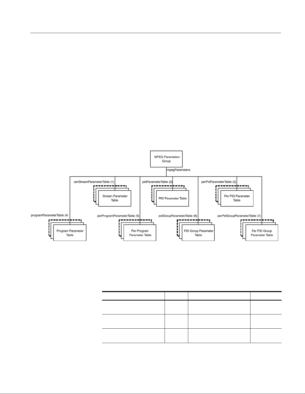
If you are using windows and have the cygwin utilities [http://www.netsnmp.org/] this can be done from the command line:
snmpset -v 1 -c public MTM400AAddress 1.3.6.1.4.1.128.5.1.17.8.1.1.2.1 i 2
Uploading the configuration slots to begin with requires an HTTP post command, which is not so easy from the command line and would require a utility
program.
MPEG Parameters Group
Figure 5−11 shows the structure of the MPEG Parameters Group, which manages
the Stream, PID, Program and PID Group parameters.
MPEG Structure
Figure 5−11: MPEG parameters group structure
Stream Parameter Table
The Stream Parameter table provides access to the stream parameters, and is
defined as:
Variable Type Use Access
perStreamParameterMifIndex
(1)
perStreamParameterIndex (2) Integer The unique Id of the required
perStreamParameterValue (3) Octet
Integer The MPEG interface associated
string
MTM400A MPEG Transport Stream Monitor Programmer Manual
with these parameters.
parameter.
The value of this parameter as
a string.
N/A
N/A
Get/Set
5−45
Page 90

MPEG Structure
PID Parameter Table
Per PID Parameter Table
The PID Parameter table provides access to the default PID parameter values,
and is defined as:
Variable Type Use Access
pidParameterMifIndex (1) Integer The MPEG interface asso-
ciated with these parameters.
pidParameterIndex (2) Integer The unique Id of the re-
quired PID parameter.
pidParameterDefaultValue (3) Octet string The default value of this
PID parameter as a string.
N/A
N/A
Get/Set
PID tests and events will inherit these values by default. Individual PID
parameters can be customized using the Per PID Parameter table.
The Per PID Parameter table provides access to individual PID parameters, and
is defined as:
Variable Type Use Access
perPidParameterMifIndex (1) Integer The MPEG interface asso-
ciated with these PID
specific parameters.
N/A
perPidParameterIndex (2) Integer The unique Id of the re-
quired PID parameter.
perPidParameterPidIndex (3) Integer The PID of interest (Pid
Number + 1).
perPidParameterValue (4) Octet string The value of this specific
PID parameter as a string.
N/A
N/A
Get/Set
5−46
MTM400A MPEG Transport Stream Monitor Programmer Manual
Page 91

MPEG Structure
Program Parameter Table
Per Program Parameter
Table
The Program Parameter table provides access to the default Program parameter
values, and is defined as:
Variable Type Use Access
programParameterMifIndex (1) Integer The MPEG interface asso-
ciated with these parameters.
programParameterIndex (2) Integer The unique Id of the re-
quired Program parameter.
programParameterDefaultValue (3) Octet string The default value of this
Program parameter as a
string.
N/A
N/A
Get/Set
Program tests and events will inherit these values by default. Individual program
parameters can be customized using the Per Program Parameter table.
The Per Program Parameter table provides access to individual Program
parameters, and is defined as:
Variable Type Use Access
perProgramParameterMifIndex (1) Integer The MPEG interface asso-
ciated with these Program
specific parameters.
N/A
perProgramParameterIndex (2) Integer The unique Id of the re-
quired Program parameter.
perProgramParameterProgramIn dex (3)
perProgramParameterValue (4) Octet string The value of this specific
Integer The Program (program
number +1) of interest.
Programs parameter as a
string.
N/A
N/A
Get/Set
MTM400A MPEG Transport Stream Monitor Programmer Manual
5−47
Page 92

MPEG Structure
PID Group Parameter
Table
Per PID Group Parameter
Table
The PID Group Parameter table provides access to the default PID group
parameter values, and is defined as:
Variable Type Use Access
pidGroupParameterMifIndex (1) Integer The MPEG interface asso-
ciated with these parameters.
pidGroupParameterIndex (2) Integer The unique Id of the re-
quired PID Group parameter.
pidGroupParameterDefaultValue (3) Octet string The default value of this
PID Group parameter as a
string.
N/A
N/A
Get/Set
PID Group tests will inherit these values by default. Individual PID group
parameters can be customized using the Per PID Group Parameter table.
The Per PID Group Parameter table provides access to individual PID group
parameters, and is defined as:
Variable Type Use Access
perPidGroupParameterMifIndex (1) Integer The MPEG interface asso-
ciated with these PID
specific parameters.
perPidGroupParameterIndex (2) Integer The unique Id of the re-
quired PID Group parameter.
perPidGroupParameterPidGroup
Index (3)
perPidGroupParameterValue (4) Octet string The value of this specific
Integer The PID Group of interest
(Group Number).
PID Groups parameter as
a string.
N/A
N/A
N/A
Get/Set
5−48
MTM400A MPEG Transport Stream Monitor Programmer Manual
Page 93

MPEG Record Group
MPEG Structure
The MPEG Record table provides the control and monitoring interface for the
MTM400A triggered recording function, and is defined as follows:
Variable Type Use Access
mpegRecordMifIndex (1) Integer The MPEG interface. N/A
mpegRecordState (2) Integer State of recording:
0 = Idle
1 = Waiting for Trigger
2 = Recording in Progress
3 = Recording Complete
mpegRecordTriggerType (3) Integer Type of recording trigger:
0 = Immediate (default)
1 = External Rising Edge
2 = External Falling Edge
3 = Event Alarm
mpegRecordLargestAllowed (4) Integer Largest number of packets
allowed to record.
mpegRecordPreTrigger (5) Integer Percentage of stream pre-
pended to the recording before
the trigger set off.
mpegRecordActualSize (6) Integer Actual size of recording in
packets.
mpegRecordTotalMemorySize
(7)
mpegRecordActivate (8) Integer Setting this to 1 arms the
Integer Total system memory size (in
Megabytes) available for
recording.
trigger, setting to 0 aborts the
arming, or stops the recording
at the current position.
Get
Get/Set
Get
Get/Set
Get
Get
Get/Set
mpegRecordClear (9) Integer Setting this clears the record-
mpegRecordTimestampAvailable
(10)
mpegRecordUseTimestamp (11) Simple
mpegRecordProgress (12) Integer The percentage of the record-
Integer Specifies whether device is
Boolean
MTM400A MPEG Transport Stream Monitor Programmer Manual
ing.
capable of time-stamping
recorded packets.
Specifies whether to timestamp packets.
ing completed.
Get/Set
Get
Get/Set
Get
5−49
Page 94

MPEG Structure
Variable AccessUseType
mpegRecordDesiredSize (13) Integer Desired size of recording in
packets.
Get/Set
mpegRecordTriggerTime (14) Octet string This returns the time at which
the trigger for the current
recording occurred, or zero if
not currently meaningful.
Get
5−50
MTM400A MPEG Transport Stream Monitor Programmer Manual
Page 95

Web Server URLs
Page 96

Page 97

Web Server URLs
Configuration
The following sections define the URLs supported by the MTM400 Web Server.
Note that using the Web interface will not enable access to option dependent
data, for example schedules or service logging.
Upload Configuration
Download Configuration
Configuration Schema
Parameter Definitions
http:://<MTM IP Address>/cgi-bin/uploadconfiguration?stream=x&slot=y
The ‘stream’ parameter is always 1 for MTM400. The slot corresponds to the
configuration slot into which the new configuration parameters will be loaded.
This is in the range 1…8.
http:://<MTM IP Address>/cgi-bin/
downloadconfiguration?stream=x&slot=y
The ‘stream’ parameter is always 1 for MTM400. The slot corresponds to the
configuration slot from which the parameters will be downloaded. This is in the
range 1…8.
http:://<MTM IP Address>/config.xsd
Editing configuration files can be difficult, however with an advanced XML
editor the process can be made easier with an XSD file. This file will allow smart
content completion and error checking.
http:://<MTM IP Address>/wmsm/configuration/parameters.xml
All the parameters in the configuration files are defined in this XML file.
http:://<MTM IP Address>/wmsm/configuration/parametermap.xml
This XML file defines the linkage between each test and the settable parameters.
MTM400A MPEG Transport Stream Monitor Programmer Manual
6−1
Page 98

Web Server URLs
Status
Stream Events
Box Events
Event Hierarchy
http:://<MTM IP Address>/cgi−bin/eventstates?start=x&end=y
http:://<MTM IP Address>/cgi−bin/boxeventstates?start=x&end=y
These URLs have optional start and end event identities; if not specified, the
MTM400A will return the status of all events.
The optimal solution is controlled status polling through SNMP. If this cannot be
implemented, then collecting all statuses through HTTP is more efficient than
polling all the events through SNMP. Collecting the statuses is intensive for the
MTM400A; the frequency of calls to this URL should be limited.
As a help to efficient event polling, you can use the test hierarchy to work out
what you need to read. The test hierarchy is exposed through XML.
http:://<MTM IP Address>/cgi−bin/rfteststructure
http:://<MTM IP Address>/cgi−bin/teststructure
http:://<MTM IP Address>/cgi−bin/infostructure
http:://<MTM IP Address>/cgi−bin/warningstructure
http:://<MTM IP Address>/cgi−bin/boxteststructure
Schedules
Upload Schedule
Download Schedule
http:://<MTM IP Address>/cgi-bin/uploadschedule?stream=x
This URL is used to upload a schedule file for the specified stream interface. The
‘stream’ parameter is always 1 for MTM400.
http:://<MTM IP Address>/cgi-bin/downloadschedule?stream=x
This URL is used to download a schedule file from the specified stream
interface. The ‘stream’ parameter is always 1 for MTM400.
6−2
MTM400A MPEG Transport Stream Monitor Programmer Manual
Page 99

Recording
Web Server URLs
Download Recording
Contolling Recording
Logging
Download Stream Log
http:://<MTM IP Address>/data/recording.mpg?start=x&end=y
This URL is used to download a stream recording. The ‘start’ and ‘end’
parameters define the range of packets of interest.
http:://<MTM IP Address>/recording/status.xml
Returns the current status of recording in XML format.
http:://<MTM IP Address>/control?arm=1&clear=1
This URL allows you to clear and/or initiate a recording.
http:://<MTM IP Address>/cgi−bin/streamlog?start=x&end=y&limit=z
This URL is used to download the stream log. The ‘start’ and ‘end’ parameters
define the range of log entries of interest. The available range of log entries can
be determined from the SNMP MIB table ‘mpegLog’.
The stream log may be very large, so the URL allows for sections of the log to
be downloaded. An XML format log file is downloaded in response to the
invocation of this URL. There is no acknowledgement required because the log
entries are only destroyed by the wrapping of its circular buffer.
You may use the limit parameter to download the last 1000 entries, for example,
without knowing the indices.
Download Device Log
MTM400A MPEG Transport Stream Monitor Programmer Manual
http:://<MTM IP Address>/cgi-bin/ devicelog?start=x&end=y
This URL is used to download the device log. The ‘start’ and ‘end’ parameters
define the range of log entries of interest. The range of log entries available can
be determined from the SNMP MIB table ‘adsysLog’.
An XML format log file is downloaded in response to the invocation of this
URL. There is no acknowledgement required because the log entries are only
destroyed by the wrapping of its circular buffer.
6−3
Page 100

Web Server URLs
The Stream and Device Log downloads can also take a language parameter.
For example,
http://<MTM IP Address>/cgi-bin/devicelog?start=x&end=y&lang=x
where x=24 (English), 52 (Japanese) or 134 (Chinese).
Log Indices
Service Logs
Download Service Log
http:://<MTM IP Address>/cgi−bin/eventlogindices
http:://<MTM IP Address>/cgi−bin/devicelogindices
Where it is not convenient to use SNMP to get the current indices, it is possible
to get this information via HTTP.
http:://<Despina IP Address>/service/log?reqid=ID
This URL results in a CSV file of service Log results being downloaded. Each
request has a unique user-defined ID that is used in the acknowledge phase.
It must be acknowledged that data has been processed fully before it can be
destroyed, so the client must make a request with a matching ‘reqid’ to clear the
data as follows:
http:://<Despina IP Address>/service/logack?reqid=ID
The PIDs involved in the service log can be specified in the configuration file or
configured by HTTP requests. The following two URLs will introduce or
remove a PID from the service log.
6−4
http:://<Despina IP Address>/service/addpid?pid=1234
http:://<Despina IP Address>/service/delpid?pid=1234
Use the following URL to return a list of current PIDs in XML format.
http://<Despina IP Address>//service/current.xml
MTM400A MPEG Transport Stream Monitor Programmer Manual
 Loading...