

Page 1
Limit and Mask Test Application Software
Option LT, MTH, MTM Data Sheet
Option MTM – Mask Test Application Software
Perform Pass/Fail Testing against Telecommunication and Computer
Standards
Customized Mask Tests allow for M ultiple Actions upon Test Failures
Detailed Test Statistics provide Insight into True Signal Behavior
Designed for use on MSO/DPO5000 Series and DPO7000 Series
Oscilloscopes
Applications
Pass/Fail Testing
ITU-T
ANSI T1.102
SONET/SDH
Features & Benefits
Option LT – Limit Test Application Software
Conduct Limit Test Pass/Fail Testing against a “Golden” Waveform with
Tolerances
Customized Limit Tests allow for Multiple Actions upon Test Failures
Designed for use on MSO/DPO5000, DPO7000, and
A/MSO70000 Series Oscilloscopes
DPO/DS
100BASE-TX, 1000BASE-CX/SX Ethernet
CPRI
USB 1.1/2.0
Fibre Channel
OBSAI
InfiniBand
MTH – Mask Test Application Software
Option
Perform Pass/Fail Testing against Telecommunication and Computer
Standards
Customized Mask Tests allow for Multiple Actions upon Test Failures
Detailed Test Statistics pro vide Insight into True Signal Behavior
Designed for use on DPO/DSA/MSO70000 Series Oscilloscopes (comes
standard on D SA70 000 Series)
Serial ATA
SAS
IEEE1394b
Rapid IO
OIF
Video Standards
Page 2
Data Sheet
Automated Pass/Fail Testing
Validating signal quality is an important part of any embedded system
design. One way to determine how well your signals conform to expected
signal quality is to use mask testing. A mask de fines a portion, or portions,
of the oscillo
The Limit Test Application Software (Option LT) makes it easier to validate
how your sign
The Mask Test Application Software (Options MTH and MTM) en ables
testing aga
providing automated statistical analysis of signal quality.
Option LT – Limit Test Application Soft ware
A common method for understanding your signal quality is to compare
against a known good or “golden” waveform. You can apply horizontal and
vertical t
used for quick, accurate Pass/Fail testing. This method is also a great way
to perform go/no-go testing on a manufacturing line by enabling repeatable,
fast decisions on the quality of a component or system. The Limit Test
Application Software allows you to save your limit test template for use later
across multiple oscilloscopes in a lab or on a production line.
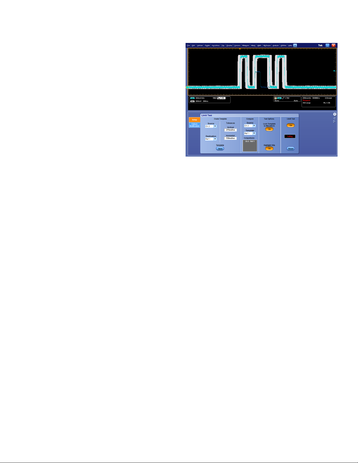
The Limit Test Application Software will highlight any waveform samples
that fall outside of the limit test template, providing you with quick visual
evidenc
scope display that a signal must not enter.
als are performing compared to a known good condition.
inst a well-defi ned telecommunication or computer standard
olerances to the golden waveform to create a template that can be
e of a failure.
finds infrequent glitches and runt signals using a mask created by adding vertical
Limit test
and horizo
waveform a
ntal tolerances around a golden waveform. Test your signals against a golden
nd quickly gain insight into anomalous behavior.
When a test failure is detected, the o scilloscope can perform a number of
actions in parallel. These actions include stopping the a cquisition, e-mailing
a message indicating the test has failed, saving a waveform to a file, logging
the date and time to a file, printing the waveform, and sending a GPIB SRQ
command.
2 www.tektronix.com
Page 3
Limit and Mask Test Application Software — Option LT, MTH, MTM
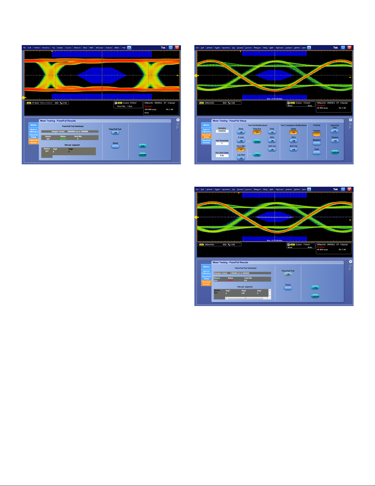
OC12 (622.
telecommu
quick and a
5 Mb/s) standard mask showing results from a mask test. A robust set of
nications and computer industry standard masks make testing to standards
ccurate.
Option MTH, MTM – Mask Test Application Software
When it is necessary to measure performance of your signals against
telecommunications or computer standard s to verify compliance and
interoperability, the Mask Test Application Software, with more than 100
standard masks, makes it easy. Each standard mask is easily loaded
from the oscilloscope internal memory and can be immediately used to
conduct P
ass/Fail testing. Adherence to a standard mask is determined
pixel-by-pixel throughout the display.
When a sta
ndard mask is loaded, the oscilloscope makes use of the
integrated Communication Trigger. Each standard mask is associated
with a communication standard and the m ask you select automatically
determines which communication trigger is used. Some models include
integrated clock recovery circuitry up to 6 Gb/s for NRZ eye patterns. Clock
recovery allows you to perform more reliable and accurate ma sk testing.
The oscilloscope can reduce setup time for making a mask test
measurement by performing an Autoset for vertical, horizontal, and trigger
ers on the source signal. Additionally, to reduce the chance of
paramet
failures, the oscilloscope can Autofit the waveform to the mask to minimize
hits within the m ask. It can do this a single time following an Autoset or it
can perform an Autofit after every triggered acquisition.
The Mask Test Application Software provides flexible test definitions
enabling you to tailor the test to your needs. You can run a test for a
user-defined number of waveforms (up to 2.14×10
9
). The Repeat Test
and Pretest Delay capability enables swapping of test locations before
ding with a test over multiple cycles of the test. You can set the
procee
number of violations that can occur before a test status is considered failed.
The oscilloscope can also perform a number of actions when a test fails or
completes. Actions the oscilloscope can perform when a test fails include
stopping the acquisition, e-mailing a message indicating the test has failed,
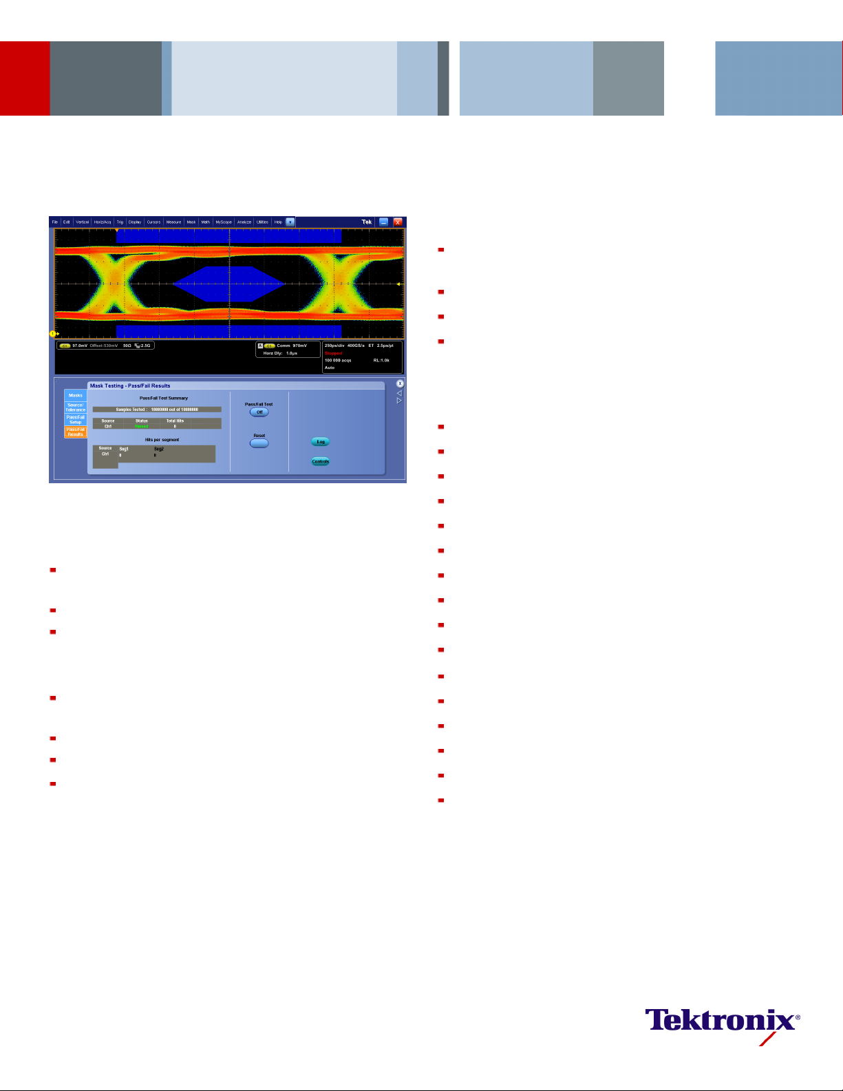
The Mask Test Application Software enables multiple actions upon a test failure or the
completion of a test, tailoring the test to your specific needs.
d mask test results show statistical information for the test. The results include
Detaile
tion on test sample size, failures, total number of hits, and the number of hits in
informa
k segment.
each mas
saving a waveform to file, logg ing the date and time of the fa ilure, printing a
waveform, sending a GPIB SRQ, and sending a trigger out pulse. Actions
the oscilloscope can perform when a test completes include sending a GPIB
SRQ and sending a trigger out pulse.
The Mask Test Application Software provides statistical results from each
ducted. The results include Pass/Fail status of the test, number
test con
of waveforms/samples tested, number of violations found, and the total
number of hits within the mask. A secondary display shows the total number
of hits in each segment of the mask providing further insight into any mask
violations.
www.tektronix.com 3
Page 4

Data Sheet
Characteristics
Option LT – Lim
Characteristic
Test Source Any Ch1 – Ch4, Math1 – Math4, R1 – R4
Template Storage
Template Creation
Margins
Lock Template to
Waveform
Highlight Hits
Limit Test Status Passed: No samples from the test source have fallen
Limit Test Control ON: Limit test is active and hits are being tracked
Reset
Actions on Limit Test
Failure
1
Not available on MSO/DPO5000 Series.
*
it Test Characteristics
Description
Limit test template can be saved into any R1 – R4
location or to a file
Vertical tolerance from 0 to 5 divisions in 0.1m
(1/10,000th) division increments
Horizontal tolerance from 0 to 5 divisions in 0.1m
(1/10,000th) division increments
Note: Use Average acquisition mode to help create a
smoother limit test template
Lock ON: Template automatically re-scales with source
channel settings changes
Lock OFF: Template does not re-scale with source
channel settings changes
Highlight Hits ON: Visually highlight any samples that fall
outside of the limit test template
Highlight Hits OFF: Samples that fall outside of the limit
test template are not visually highlighted
outside of the limit test template
Failed: At least one sample from the test source has
fallen outside of the limit test template
OFF: Limit test is not active and hits are not being
tracked
Clears all violations in preparation for another test
Stop Acq: When Stop Acq is ON, the instrument stops
acquiring if a limit test fails
1
Beep*
: When Beep is ON, the instrument beeps if a limit
test fails
E-mail: When E-mail is ON, the instrument sends an
e-mail if the limit test fails
Save Waveform: When Save Wfm is ON, failed
waveform data is saved to a file
Log Date: When Log Date is ON, the date and time for
each failed limit test is recorded to a file
Print: When Print is ON, the instrument sends the
waveform to a printer if a limit test fails
SRQ: When SRQ is ON, the instrument sends a GPIB
SRQ command if a limit test fails
Option MTH, MTM – Mask Test Characteristics
Characteristic
Description
TestSource AnyCh1–Ch4,M1–M4,R1–R4
Mask Creation Select standard mask from internal memory
Load custom mask from text file with up to 16 mask
segments
Copy a standard m ask to user mask and edit
Included Standard M ask
Types
ITU-T
The standards available vary by model depending on the
bandwidth and configuration of the instrument
DS0 Single (64 kb/s)
DS0 Double (64 kb/s)
DS0DataContra(64kb/s)
DS0 Timing (64 kb/s)
DS1 Rate (1.544 Mb/s)
E1 Sym Pair (2.048 Mb/s)
E1 Coax Pair (2.048 Mb/s)
Clk Intf. Sym (2.048 Mb/s)
Clk Intf. Coax (2.048 Mb/s)
DS2RateSym(6.312Mb/s)
DS2 Rate Coax (6.312 Mb/s)
E2 (8.448 Mb/s)
32Mb (32.064 Mb/s)
E3 (34.368 Mb/s)
DS3 Rate (44.736 Mb/s)
97Mb (97.728 Mb/s)
E4 Binary 0 (139.26 Mb/s)
E4 Binary 1 (139.26 Mb/s)
STM1E Binary 0 (155.52 Mb/s)
STM1E Binary 1 (155.52 Mb/s)
STM-0 HDBx (51.84 Mb/s)
STM-0CMI0(51.84Mb/s)
STM-0CMI1(51.84Mb/s)
ANSI T1.102 DS1 (1.544 Mb/s)
DS1A (2.048 Mb/s)
DS1C (3.152 Mb/s)
DS2 (6.312 Mb/s)
DS3 (44.736 Mb/s)
DS4NA (139.26 Mb/s)
DS4NA Max Output (139.26 Mb/s)
STS-1 Pulse (51.84 Mb/s)
STS-1 Eye (51.84 Mb/s)
STS-3 (155.52 Mb/s)
STS-3 Max Output (155.52 Mb/s)
SONET/SDH OC1/STM0 (51.84 Mb/s)
OC3/STM1 (155.52 Mb/s)
OC12/STM4 (622.08 Mb/s)
OC48/STM16 (2.4883 Gb/s)
OC48/STM16 FEC (2.666 Gb/s)
Ethernet
100BASE-TX STP (125 Mb/s)
100BASE-TX UTP (125 Mb/s)
1000B-SX/LX/PX (1.25 Gb/s)
1000B-CX Norm, TP2 (1.25 Gb/s)
1000B-CX Abs, TP2 (1.25 Gb/s)
1000B-CX Abs, TP3 (1.25 Gb/s)
XAUI, Near (3.125 Gb/s)
XAUI, Far (3.125 Gb/s)
CPRI (Common
Public Radio
Interface)
CPRI1228 (1.228 Gb/s)
CPRI2457 (2.457 Gb/s)
CPRI3072 (3.072 Gb/s)
USB 1.1/2.0 FS (12 Mb/s)
HS:T1(480Mb/s)
HS:T2(480Mb/s)
HS:T3(480Mb/s)
HS:T4(480Mb/s)
HS:T5(480Mb/s)
HS:T6(480Mb/s)
4 www.tektronix.com
Page 5

Limit and Mask Test Application Software — Option LT, MTH, MTM
Characteristic
Fibre Channel FC133 Optical (132.8 Mb/s)
Fibre Channel
Electrical
OBSAI (Open Base
Station Architecture
Initiative)
iBand
Infin
Serial ATA G1 Tx 5-Cycle (1.5 Gb/s)
AS
S
Description
FC266 Optical (265.62 Mb/s)
FC531 Optical (531.25 Mb/s)
FC1063 Optical (1.0625 Gb/s)
FC1063 Optical Draft Rev 11
FC2125 Optical (2.125 Gb/s)
FC133E Elec. (132.8 Mb/s)
FC266E Elec. (265.62 Mb/s)
FC531E Elec. (531.25 Mb/s)
FC1063E Elec. (1.0625 Gb/s)
FC1063E Norm, Beta, Transm
FC1063E Norm, Delta, Transm
FC1063E Norm, Gamma, Transm
FC1063E Abs, Beta, Transm
FC1063E Abs, Delta, Transm
FC1063E Abs, Gamma, Transm
FC1063E Abs, Beta, Recv
FC1063E Abs, Delta, Recv
FC1063E Abs, Gamma, Recv
FC2125E Norm, Beta, Transm
FC2125E Norm, Delta, Transm
FC2125E Norm, Gamma, Transm
FC2125E Abs, Beta, Transm
FC2125E Abs, Delta, Transm
FC2125E Abs, Gamma, Transm
FC2125E Abs, Beta, Recv
FC2125E Abs, Delta, Recv
FC2125E Abs, Gamma, Transm
FC4250E Norm, Beta, Transm
FC4250E Norm, Delta, Transm
FC4250E Norm, Gamma, Transm
FC4250E Abs, Beta, Transm
FC4250E Abs, Delta, Transm
FC4250E Abs, Gamma, Transm
FC4250E Abs, Beta, Recv
FC4250E Abs, Delta, Recv
FC4250E Abs, Gamma, Recv
OBSAI3072_Tx (3.072 Gb/s)
OBSAI3072_Rx (3.072 Gb/s)
OBSAI6144_Tx (6.144 Gb/s)
OBSAI6144_Rx (6.144 Gb/s)
ptical (2.5 Gb/s)
2.5 O
Electrical (2.5 Gb/s)
2.5
G1 Rx 5-Cycle (1.5 Gb/s)
G2 Tx 5-Cycle (3.0 Gb/s)
G2 Rx 5-Cycle (3.0 Gb/s)
G3 Tx 5-Cycle (6.0 Gb/s)
G3 Rx 5-Cycle (6.0 Gb/s)
AS IR (1.5 Gb/s)
S
AS CR (1.5 Gb/s)
S
AS XR (1.5 Gb/s)
S
SAS IR, AASJ (1.5 Gb/s)
SAS CR, AASJ (1.5 Gb/s)
SAS XR, AASJ (1.5 Gb/s)
SAS, SATA (1.5 Gb/s)
SAS IR (3.0 Gb/s)
SAS CR (3.0 Gb/s)
SAS XR (3.0 Gb/s)
SAS IR, AASJ (3.0 Gb/s)
SAS CR, AASJ (3.0 Gb/s)
SAS XR, AASJ (3.0 Gb/s)
SAS, SATA (3.0 Gb/s)
Characteristic
IEEE 1394b
Rapid IO LP-LVDS Drv (500 Mb/s)
Rapid IO Serial RIO Serial (1.25 Gb/s)
OIF Standards SFI/SPI-5 TA Data (2.488 Gb/s)
PCI Express PCI-Express Transm (2.5 Gb/s)
Video
Mask Polarity
Mask Display
Lock Mask to Waveform Lock to Waveform ON: Mask automatically re-scales with
Hit Counts ON: Any hit in any mask segment will be counted and
Highlight Hits
Description
S400b T1 (491.5 Mb/s)
S400b T2 (491.5 Mb/s)
S400ß Optical (491.5 Mb/s)
S800b T1 (983.0 Mb/s)
S800b T2 (983.0 Mb/s)
S800 ß Optical (983.0 Mb/s)
S1600b T1 (1.966 Gb/s)
S1600b T2 (1.966 Gb/s)
S1600ß Optical (1.966 Gb/s)
Drv (750 Mb/s)
Drv (1.0 Gb/s)
Drv (1.5 Gb/s)
Drv (2.0 Gb/s)
Ext Drv (500 Mb/s)
Ext Drv (750 Mb/s)
Ext Drv (1.0 Gb/s)
Ext Drv (1.5 Gb/s)
Ext Drv (2.0 Gb/s)
Rcv (500 Mb/s)
Rcv (750 Mb/s)
Rcv (1.0 Gb/s)
Rcv (1.5 Gb/s)
Rcv (2.0 Gb/s)
RIO Serial (2.5 Gb/s)
RIO Serial (3.125 Gb/s)
SFI/SPI-5TCData(2.488Gb/s)
SFI/SPI-5 TA Clk (2.488 Gb/s)
SFI/SPI-5 TC Clk (2.488 Gb/s)
SFI/SPI-5 RB Data (2.488 Gb/s)
SFI/SPI-5 RD Data (2.488 Gb/s)
SFI/SPI-5 RB Clk (2.488 Gb/s)
SFI/SPI-5 RD Clk (2.488 Gb/s)
SFI/SPI-5 TA Data (3.125 Gb/s)
SFI/SPI-5TCData(3.125Gb/s)
SFI/SPI-5 TA Clk (3.125 Gb/s)
SFI/SPI-5 TC Clk (3.125 Gb/s)
SFI/SPI-5 RB Data (3.125 Gb/s)
SFI/SPI-5 RD Data (3.125 Gb/s)
SFI/SPI-5 RB Clk (3.125 Gb/s)
SFI/SPI-5 RD Clk (3.125 Gb/s)
VSR OC192/STM64 (1.24416 Gb/s)
TFI-5 (2.488 Gb/s)
TFI-5 (3.1104 Gb/s)
PCI-Express Recv (2.5 Gb/s)
4FSC NTSC "D2" (143.18 Mb/s)
4:4:2 "D1" (270Mb/s)
DVB ASI (270 Mb/s)
4:2:2 SMPTE 259M-D (360 Mb/s)
SMPTE 292M (1.485 Gb/s)
This control is only displayed for certain mask types. Use
this control to select Positive or Negative polarity for the
mask
ON: Mask display is on
OFF: Mask will not be displayed
source channel settings changes
Lock to Waveform OFF: Mask does no t re-scale with
source channel settings changes
displayed in the Pass/Fail Test Summary
OFF: Hits in mask segments will not be counted
Highlight Hits ON: Visually highlight any samples that fall
within a mask segment
Highlight Hits OFF: Samples that fall inside of a mask
segment are not visually highlighted
www.tektronix.com 5
Page 6

Data Sheet
Characteristic
Mask Alignment:
Autoset
Description
Use Mask Autoset to automatically align the source
signal within the mask
Parameters that can be used in the Mask Autoset
procedure include: Vertical (Scale, Position, DC
Compensation), Horizontal (Scale, Position), and Trigger
Autoset Mode: Select Auto to have Autoset performed
after a standard mask has been selected. Select Manual
to make adjustments manually
Autofit Once: The waveform is autofit once following an
autoset
Mask Alignment: Autofit ON: The waveform is autofittothemaskandwill
minimize hits within the mask on each acquisition
OFF: The waveform will not be autofit to the mask on
each acquisition
Controls for setting the vertical and horizontal maximum
levels of adjustment are available
Mask Margin Tolerance
ON: The percentage of margin used in the mask test is
user-controllable
OFF: The percentage of margin used in the mask test is
not user-controllable
Range: –50% to +50% in 1% increments; A margin of
<0% moves mask segments further apart, making a
mask test easier to pass. A margin of >0% moves mask
segments closer together, demonstrating that the signal
passes the test with margin for further error
Test Criteria Run Until Minimum number of samples (from 5,000 to 2.14×10⁹)
when in WfmDB acquisition mode. Minimum number of
waveforms (from 1 to 2.14×10
9
) in all other acquisition
modes
User Mask Edit
Modify a User Mask through an intuitive graphical user
interface
Select a mask segment and vertex to edit, and then set
the horizontal and vertical values
Addordeletesegmentsinanexistingmaskorverticesin
an existing mask segment
Saveamasktoafile, or recall a mask from a file
Pretest Delay From 0 s to 60 s
Fail Threshold From 1 to 2.14×10
9
Pass/Fail Test Control ON: Test is started and runs until completed or manually
stopped
OFF: Test is not running
Repeat on Completion ON: Test will repeat when the minimum number of
waveforms or minimum amount of time is reached
OFF: Test will run a single time and will not repeat
Mask Polarity Positive, Negative, or Both. Test will complete with the
selected mask polarity. When Both is selected the test
will run with Positive polarity and with Negative polarity
Actions on Mask Test
Failure
Stop Acq: When Stop Acq is ON, the instrument stops
acquiring if a mask test fails
1
Beep*
: When Beep is ON, the instrument beeps if a limit
test fails
E-mail: When E-mail is ON, the instrument sends an
e-mail if the limit test fails
Save Waveform: When Save Wfm is ON, failed
waveform data is saved to a file
Log Date: When Log Date is ON, the date and time for
each failed limit test is recorded to a file
Print: When Print is ON, the instrument sends the
waveform to a printer if a limit test fails
SRQ: When SRQ is ON, the instrument sends a GPIB
SRQ command if a limit test fails
AUX Out: When AUX Out is ON, the instrument sends a
trigger to the Auxiliary Out connector when a mask test
fails
Characteristic
Actions on Mask Test
Complete
Description
1
Beep*
: W hen Beep is ON, the instrument beeps when
the mask test is complete
SRQ: When SRQ is ON, the instrument sends a GPIB
SRQ command when the mask test is complete
AUX Out: When AUX Out is ON, the instrument sends a
trigger to the Auxiliary Out connector when a mask test
is complete
Pass/Fail Results
Display
Pass/Fail Test Summary: Includes information on the
outcome of a test
Samples Tested: Shows the current number of
samples tested out of the total number to be tested
Source: Indicates what signal source was used for the
test
Status: Indicates whether the test has Passed, Failed,
or is Passing
Total Hits: The total number of data points that
violated the mask
Failed Wfms: The total number of waveforms that
failed during the test
Hits per Segment: The number of hits that have violated
each segment in the mask
*1Not available on MSO/DPO5000 Series.
Ordering Information
Limit Test Application Software
Model New Instrument
MSO/DPO5000
Orders
Opt. LT DPO-UP Opt. LT DPOFL-LT
Series
DPO7000 Series Opt. LT DPO-UP Opt. LT DPOFL-LT
DPO/DSA/MSO70000
Opt. LT DPO-UP Opt. LT DPOFL-LT
Series
Mask Test Application Software
Model New Instrument
MSO/DPO5000
Orders
Opt. MTM DPO-UP Opt. MTM DPOFL-MTM
Series
DPO7000 Series Opt. MTM DPO-UP Opt. MTM DPOFL-MTM
DPO/MSO70000
Opt. MTH DPO-UP Opt. MTH DPOFL-MTH
Series
DSA70000 Series Standard Standard Standard
Recommended Probes
Please refer to www.tek.com/probes for further information on the
recommended models of probes and any necessary probe adapters.
t(s) are manufactured in ISO registered facilities.
Produc
Product
Upgrades
Product
Upgrades
Floating
Licenses
Floating
Licenses
6 www.tektronix.com
Page 7

Limit and Mask Test Application Software — Option LT, MTH, MTM
www.tektronix.com 7
Page 8

Data Sheet
Contact Tektronix:
ASEAN / Australa
Balkans, Israel, South Africa and other ISE Countries +41 52 675 3777
Central East Eu
Mexico, Central/South America & Caribbean (52) 56 04 50 90
* European toll-free number. If not accessible, call: +41 52 675 3777
rope, Ukraine, and the Baltics +41 52 675 3777
Central Europe & Greece +41 52 675 3777
Middle E ast,
Asia, and North Africa +41 52 675 3777
The Netherlands 00800 2255 4835*
People’s Rep
Republic of
United K ingdom & Ireland 00800 2255 4835*
sia (65) 6356 3900
Austria 00800 2255 4835*
Belgium 00800 22
Brazil +55(11)37597600
Canada 1 800 833 9200
Denmark +4580881401
Finland +41526
France 00800 2255 4835*
Germany 00800 2255 4835*
Hong Kong 400 8
India 000 800 650 1835
Italy 00800 2255 4835*
Japan 81 (3) 67
Luxembourg +41526753777
ublic of China 400 820 5835
Poland +41 52 675 3777
Korea 001 800 8255 2835
Russia & CIS +7 (495) 7484900
South Africa +41526753777
Spain 00800
Sweden 00800 2255 4835*
Switzerland 00800 2255 4835*
Tai wa n 886 (
55 4835*
75 3777
20 5835
14 3010
Norway 800 16098
Portugal 80 08 12370
2255 4835*
2) 2722 9622
USA 1 800 833 9200
Updated 25 May 2010
www.tektronix.com
For Further Information. Tektronix maintains a comprehensive, constantly expanding
collection of application notes, technical briefs and other resources to help engineers working
on the cutting edge of technology. Please visit www.tektronix.com
t © Tektronix, Inc. All rights reserved. Tektronix products are covered by U.S. and foreign patents,
Copyrigh
d pending. Information in this publication supersedes that in all previously published material.
issued an
tion and price change privileges reserved. TEKTRONIX and TEK are registered trademarks of
Specifica
x, Inc. All other trade names referenced are the service marks, trademarks, or registered trademarks
Tek t ro n i
espective companies.
of their r
11 Nov 2010 61W-26237-0
 Loading...