

Tektronix MTG100,MTG300 Rackmount Field Install Instructions

Instructions
040-1665-00
MTG100 & MTG300
Rackmount (Option 1R) Upgrade Kit
061-A020-50
Warning
The servicing instructions are for use by qualified
personnel only. To avoid personal injury, do not
perform any servicing unless you are qualified to
do so. Refer to all safety summaries prior to
performing service.
www.tektronix.com
*P061A02050*
061A02050

Copyright © Tektronix Japan, Ltd. All rights reserved.
Copyright © Tektronix, Inc. All rights reserved.
Tektronix products are covered by U.S. and foreign patents, issued and pending. Information in this publication supercedes
that in all previously published material. Specifications and price change privileges reserved.
Tektronix Japan, Ltd., 5 --9--31 Kitashinagawa, Shinagawa--ku, Tokyo 141--0001 Japan
Tektronix, Inc., P.O. Box 500, Beaverton, OR 97077
TEKTRONIX and TEK are registered trademarks of Tektronix, Inc.

Service Safety Summary
Only qualified personnel should perform service procedures. Read this Service
Safety Summary and the General Safety Summary in the product service manual
or the instruction manual.
Do Not Service Alone. Do not perform internal service or adjustments of this
product unless another person capable of rendering first aid and resuscitation is
present.
Disconnect Power. To avoid electric shock, switch off the instrument power, then
disconnect the power cord from the mains power.
Use Care When Servicing With Power On. Dangerous voltages or currents may
exist in this product. Disconnect power, remove battery (if applicable), and
disconnect test leads before removing protective panels, soldering, or replacing
components.
To avoid electric shock, do not touch exposed connections.
MTG100 and MTG300 Rackmount Upgrade Instructions
1

Service Safety Summary
2
MTG100 and MTG300 Rackmount Upgrade Instructions
Kit Description
NOTE. The following conventions apply throughout this document:
H The MTG100 and MTG300 MPEG Generator is simply referred to as the
“MPEG generator.”
H The MPEG generator is referred to as being either a “standard” or
“Option 1R” version. The “standard” MPEG generator does not include
rackmounting hardware. The “Option 1R” MPEG generators have
rackmounting hardware on the sides of the instrument’s cabinet.
The MTG100 and MTG300 Rackmount (Option 1R) Upgrade Kit provides parts
and instructions for you to perform the following tasks:
H Replace the standard cabinet on your MPEG generator with an Option 1R
(rackmount ready) cabinet
H Install the MPEG generator into a standard 19-inch equipment rack
If your MPEG generator was ordered with Option 1R, Tektronix shipped the
MPEG generator with the rackmount cabinet already installed. If this is your
case, you will need to perform only the instructions for mounting your MPEG
generator into an equipment rack.
Products
NOTE. A standard equipment rack has rails with universal hole spacing. If your
equipment rack uses hole spacing that is different than universal hole spacing,
you may have to drill additional mounting holes in the rack to accommodate the
mounting hardware included in this kit.
CAUTION. Mounting the MPEG generator into an equipment rack requires
certain minimum clearances around the instrument. Be sure to read the
information in Environmental Requirements before you install the MPEG
generator into an equipment rack.
If you rackmount the MPEG generator using methods that are different than
those described in these instructions, the MPEG generator may not meet its
warranted specifications.
MTG100 and MTG 300 MPEG Generators All Instruments
MTG100 and MTG300 Rackmount Upgrade Instructions
3

Kit Description
Environmental Requirements
Mounting the MPEG generator into an equipment rack requires certain minimum
clearances around the instrument. When the MPEG generator is installed in an
equipment rack according to the instructions in this document, the rackmounted
MPEG generator m eets all warranted specifications.
The rack into which the rack-adapted MPEG generator is mounted must provide
the following clearance requirements:
CAUTION. If you adhere to these clearance requirements when you rackmount the
MPEG generator, the instrument will have sufficient air circulation and room to
accommodate the power cord and mounting hardware. Failure to provide t hese
clearances can result in overheating and can cause the MPEG generator to not
operate properly and/or fail.
H A minimum of 50 mm (2 inches) of vertical space above the instrument.
H A minimum of 75 mm (3 inches) of rear space.
H A minimum width of 455 mm (17.9 inches) between the left- and right-front
rails in the rack.
H A minimum inside height depth of at least 635 mm (25 inches).
Figure 1 shows the dimensions of the MPEG generator after the rackmount
cabinet is installed.
4
MTG100 and MTG300 Rackmount Upgrade Instructions
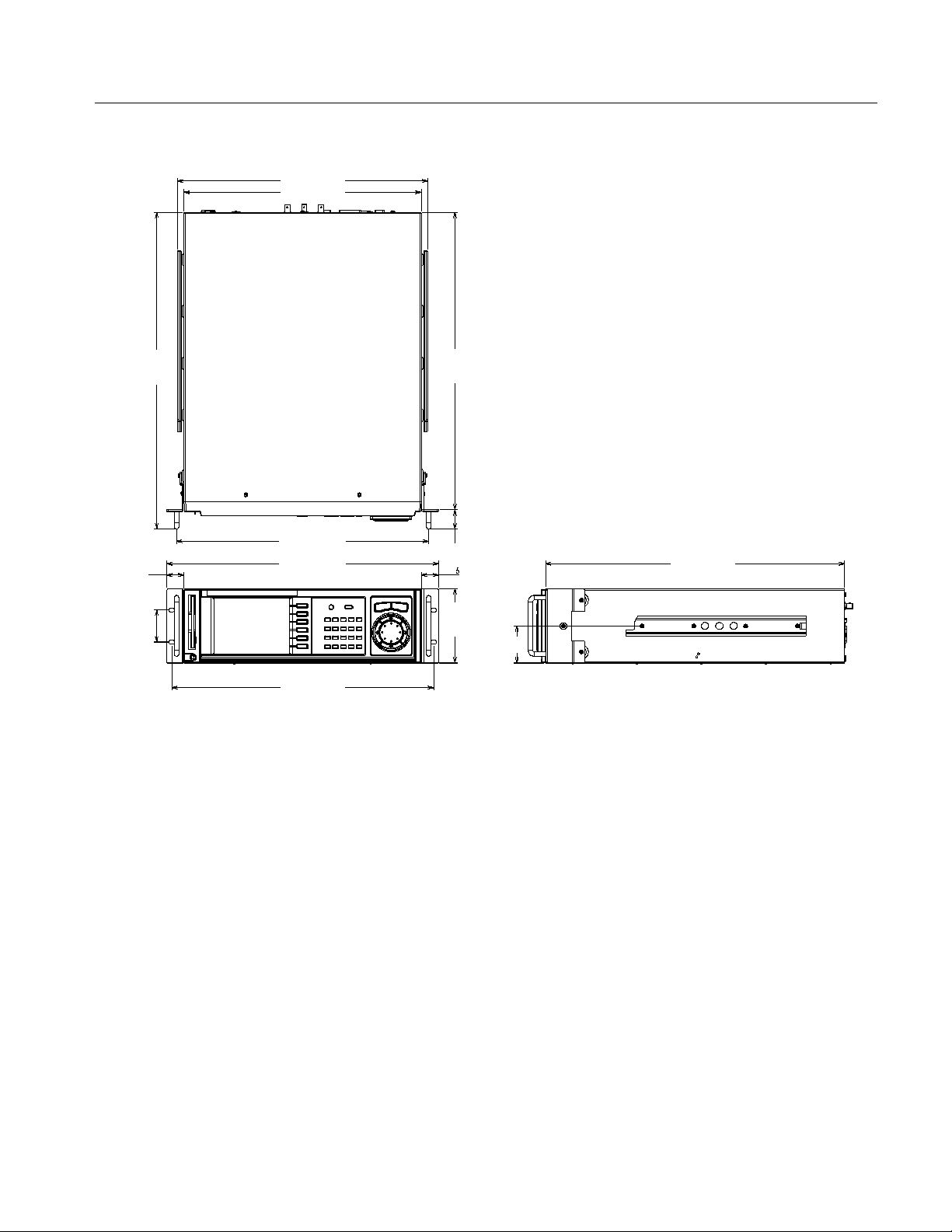
444.6 (17.5)
421.6 (16.6)
Kit Description
528.4
(20.8)
34.0 (1.3)
30.5 (1.2)
132.0
(5.2)
30.5 (1.2)
57.2 (2.3)
562.4
(22.1)
448.4 (17.7)
482.6 (19.0)
465.2 (18.3)
Figure 1: The MPEG Generator with Rack Adapter Installed
531.4 (20.9)
66.0 (2.6)
MTG100 and MTG300 Rackmount Upgrade Instructions
5
Kit Description
Required Tool and Equipment List
Table 1 lists the tools required to install the rack-adapter hardware,and to mount
the rack-adapted MPEG generator into a standard 19-inch equipment rack. All
tools are standard tools that are readily available. Depending on the type of
installation you are doing, you may not need every item in this list.
Table 1: Tools required for rackmount installation
Item
no.
Name Description
1 Screwdriver handle
(magnetic)
2 #2 Phillips tip PhillipsR-driver tip for M3 size screw heads
3 No. 2 Pozidrive tip PozidriveR-driver tip for number 2 size screw heads
Accepts
1
@
inch hex-head driver tips
4
Kit Parts List
Table 2 lists the parts included in the MTG100 and MTG300 Rackmount
(Option 1R) Upgrade Kit. See Figure 2.
Table 2: Rackmount kit parts list
Part number Quantity Description
NS 1 MTG100 and MTG300 rackmount cabinet, assembled
Replaceable Mechanical Parts on page 21 lists the part
numbers for the replaceable parts of the rackmount cabinet.
351-0623-00 1 Slide--out Tracks kit
(both side tracks and mounting hardware are included)
211-0785-00 4 Screws, M3 X 6 mm
211-0945-00 6 Screws, M3 X 8 mm
NS 1 Marker, Ident, 040-1665-XX
061-A020-50 1 Rackmount kit instructions
NS -- Not Saleable
6
MTG100 and MTG300 Rackmount Upgrade Instructions
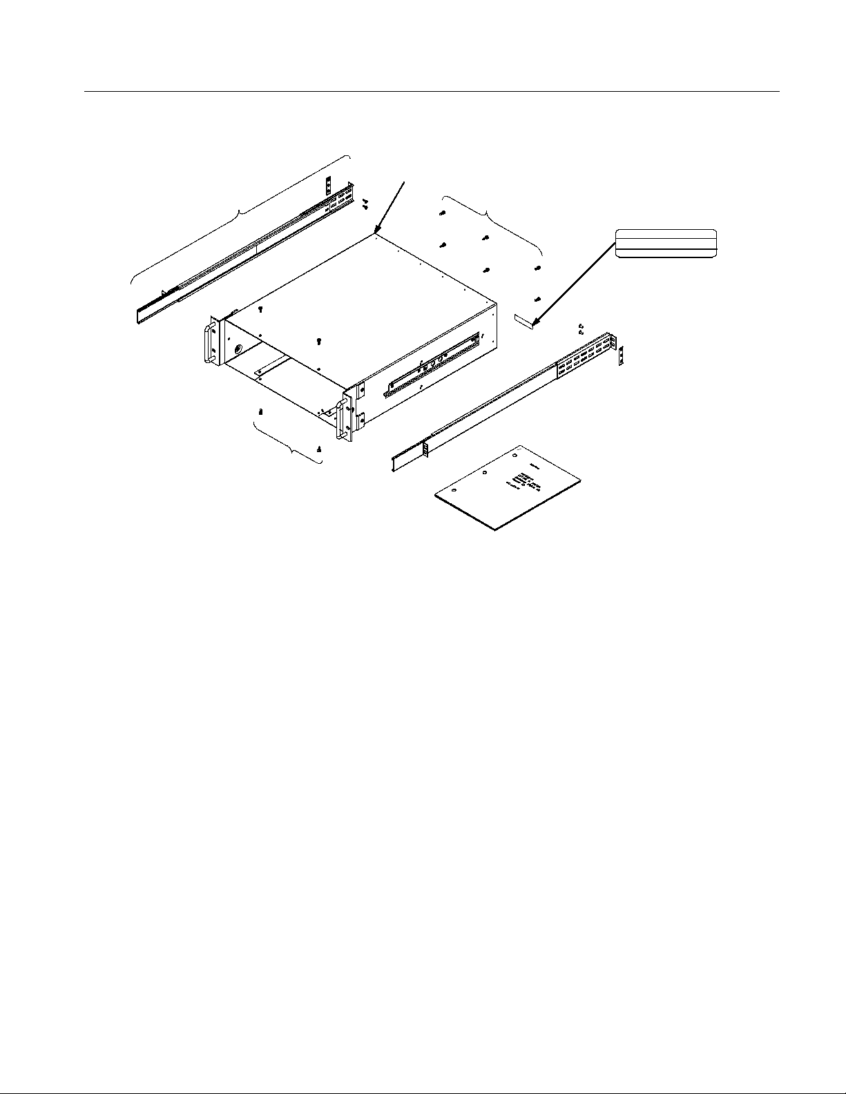
Slide--out
tracks kit
Screws,
M3 X 6 mm
MTG100 and MTG300 rackmount
cabinet, assembled
Screws, M3 X 8 mm
Marker, Ident
Tektronix Japan, Ltd. Made in JAPAN
Rackmount kit
instructions
IDENT NO.
040---1665 --- 00
Kit Description
Figure 2: Included parts of the MTG100 & MTG300 Rackmount (Option 1R) Upgrade Kit
MTG100 and MTG300 Rackmount Upgrade Instructions
7
 Loading...