

Page 1

Instructions
040-1665-00
MTG100 & MTG300
Rackmount (Option 1R) Upgrade Kit
061-A020-50
Warning
The servicing instructions are for use by qualified
personnel only. To avoid personal injury, do not
perform any servicing unless you are qualified to
do so. Refer to all safety summaries prior to
performing service.
www.tektronix.com
*P061A02050*
061A02050
Page 2

Copyright © Tektronix Japan, Ltd. All rights reserved.
Copyright © Tektronix, Inc. All rights reserved.
Tektronix products are covered by U.S. and foreign patents, issued and pending. Information in this publication supercedes
that in all previously published material. Specifications and price change privileges reserved.
Tektronix Japan, Ltd., 5 --9--31 Kitashinagawa, Shinagawa--ku, Tokyo 141--0001 Japan
Tektronix, Inc., P.O. Box 500, Beaverton, OR 97077
TEKTRONIX and TEK are registered trademarks of Tektronix, Inc.
Page 3

Service Safety Summary
Only qualified personnel should perform service procedures. Read this Service
Safety Summary and the General Safety Summary in the product service manual
or the instruction manual.
Do Not Service Alone. Do not perform internal service or adjustments of this
product unless another person capable of rendering first aid and resuscitation is
present.
Disconnect Power. To avoid electric shock, switch off the instrument power, then
disconnect the power cord from the mains power.
Use Care When Servicing With Power On. Dangerous voltages or currents may
exist in this product. Disconnect power, remove battery (if applicable), and
disconnect test leads before removing protective panels, soldering, or replacing
components.
To avoid electric shock, do not touch exposed connections.
MTG100 and MTG300 Rackmount Upgrade Instructions
1
Page 4

Service Safety Summary
2
MTG100 and MTG300 Rackmount Upgrade Instructions
Page 5
Kit Description
NOTE. The following conventions apply throughout this document:
H The MTG100 and MTG300 MPEG Generator is simply referred to as the
“MPEG generator.”
H The MPEG generator is referred to as being either a “standard” or
“Option 1R” version. The “standard” MPEG generator does not include
rackmounting hardware. The “Option 1R” MPEG generators have
rackmounting hardware on the sides of the instrument’s cabinet.
The MTG100 and MTG300 Rackmount (Option 1R) Upgrade Kit provides parts
and instructions for you to perform the following tasks:
H Replace the standard cabinet on your MPEG generator with an Option 1R
(rackmount ready) cabinet
H Install the MPEG generator into a standard 19-inch equipment rack
If your MPEG generator was ordered with Option 1R, Tektronix shipped the
MPEG generator with the rackmount cabinet already installed. If this is your
case, you will need to perform only the instructions for mounting your MPEG
generator into an equipment rack.
Products
NOTE. A standard equipment rack has rails with universal hole spacing. If your
equipment rack uses hole spacing that is different than universal hole spacing,
you may have to drill additional mounting holes in the rack to accommodate the
mounting hardware included in this kit.
CAUTION. Mounting the MPEG generator into an equipment rack requires
certain minimum clearances around the instrument. Be sure to read the
information in Environmental Requirements before you install the MPEG
generator into an equipment rack.
If you rackmount the MPEG generator using methods that are different than
those described in these instructions, the MPEG generator may not meet its
warranted specifications.
MTG100 and MTG 300 MPEG Generators All Instruments
MTG100 and MTG300 Rackmount Upgrade Instructions
3
Page 6

Kit Description
Environmental Requirements
Mounting the MPEG generator into an equipment rack requires certain minimum
clearances around the instrument. When the MPEG generator is installed in an
equipment rack according to the instructions in this document, the rackmounted
MPEG generator m eets all warranted specifications.
The rack into which the rack-adapted MPEG generator is mounted must provide
the following clearance requirements:
CAUTION. If you adhere to these clearance requirements when you rackmount the
MPEG generator, the instrument will have sufficient air circulation and room to
accommodate the power cord and mounting hardware. Failure to provide t hese
clearances can result in overheating and can cause the MPEG generator to not
operate properly and/or fail.
H A minimum of 50 mm (2 inches) of vertical space above the instrument.
H A minimum of 75 mm (3 inches) of rear space.
H A minimum width of 455 mm (17.9 inches) between the left- and right-front
rails in the rack.
H A minimum inside height depth of at least 635 mm (25 inches).
Figure 1 shows the dimensions of the MPEG generator after the rackmount
cabinet is installed.
4
MTG100 and MTG300 Rackmount Upgrade Instructions
Page 7
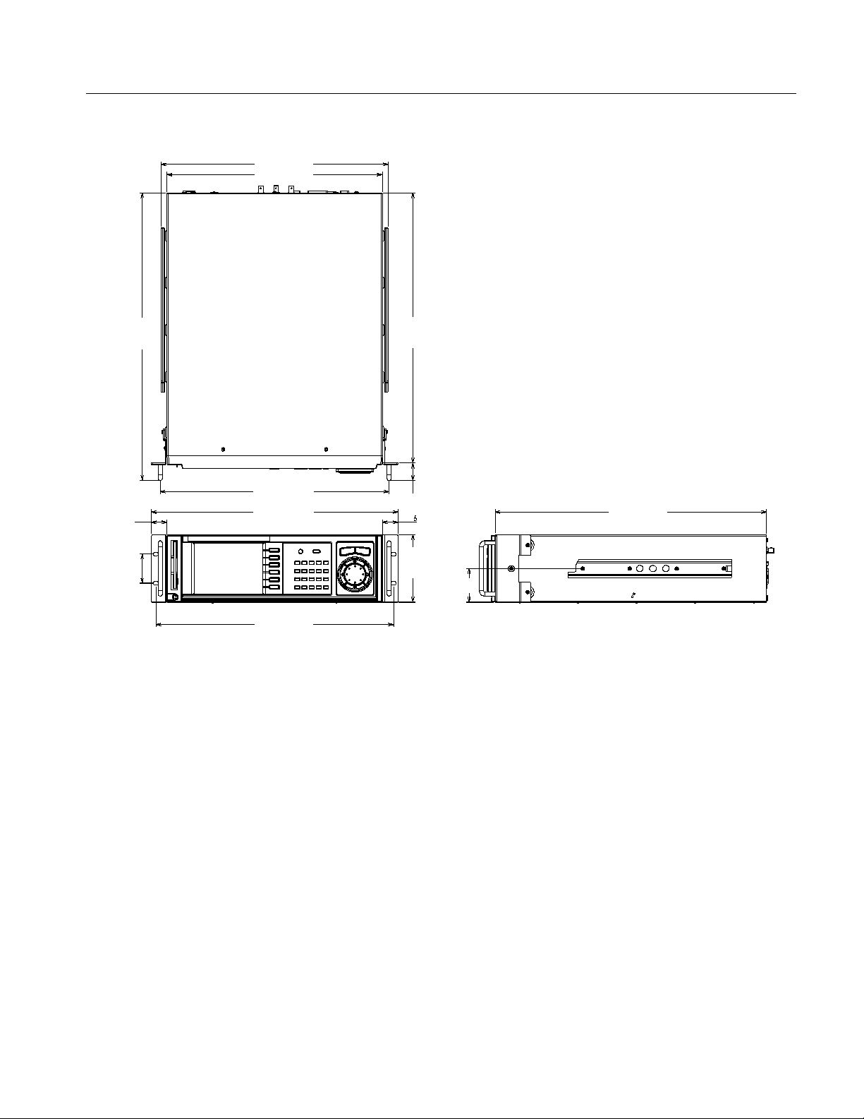
444.6 (17.5)
421.6 (16.6)
Kit Description
528.4
(20.8)
34.0 (1.3)
30.5 (1.2)
132.0
(5.2)
30.5 (1.2)
57.2 (2.3)
562.4
(22.1)
448.4 (17.7)
482.6 (19.0)
465.2 (18.3)
Figure 1: The MPEG Generator with Rack Adapter Installed
531.4 (20.9)
66.0 (2.6)
MTG100 and MTG300 Rackmount Upgrade Instructions
5
Page 8
Kit Description
Required Tool and Equipment List
Table 1 lists the tools required to install the rack-adapter hardware,and to mount
the rack-adapted MPEG generator into a standard 19-inch equipment rack. All
tools are standard tools that are readily available. Depending on the type of
installation you are doing, you may not need every item in this list.
Table 1: Tools required for rackmount installation
Item
no.
Name Description
1 Screwdriver handle
(magnetic)
2 #2 Phillips tip PhillipsR-driver tip for M3 size screw heads
3 No. 2 Pozidrive tip PozidriveR-driver tip for number 2 size screw heads
Accepts
1
@
inch hex-head driver tips
4
Kit Parts List
Table 2 lists the parts included in the MTG100 and MTG300 Rackmount
(Option 1R) Upgrade Kit. See Figure 2.
Table 2: Rackmount kit parts list
Part number Quantity Description
NS 1 MTG100 and MTG300 rackmount cabinet, assembled
Replaceable Mechanical Parts on page 21 lists the part
numbers for the replaceable parts of the rackmount cabinet.
351-0623-00 1 Slide--out Tracks kit
(both side tracks and mounting hardware are included)
211-0785-00 4 Screws, M3 X 6 mm
211-0945-00 6 Screws, M3 X 8 mm
NS 1 Marker, Ident, 040-1665-XX
061-A020-50 1 Rackmount kit instructions
NS -- Not Saleable
6
MTG100 and MTG300 Rackmount Upgrade Instructions
Page 9
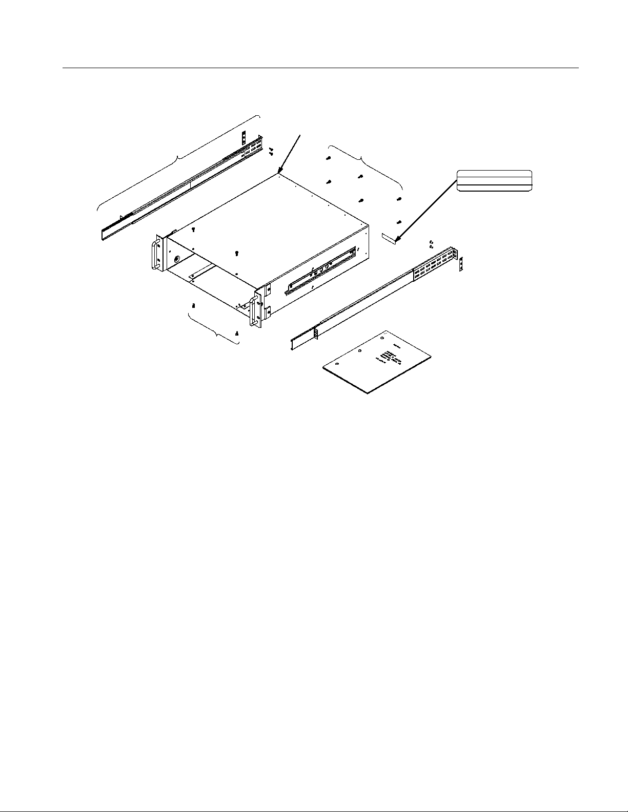
Slide--out
tracks kit
Screws,
M3 X 6 mm
MTG100 and MTG300 rackmount
cabinet, assembled
Screws, M3 X 8 mm
Marker, Ident
Tektronix Japan, Ltd. Made in JAPAN
Rackmount kit
instructions
IDENT NO.
040---1665 --- 00
Kit Description
Figure 2: Included parts of the MTG100 & MTG300 Rackmount (Option 1R) Upgrade Kit
MTG100 and MTG300 Rackmount Upgrade Instructions
7
Page 10

Kit Description
8
MTG100 and MTG300 Rackmount Upgrade Instructions
Page 11

Installation Instructions
These instructions are written for personnel who are familiar with servicing the
MPEG generator. If you need further details for disassembling or reassembling
the instrument, refer to the MTG100 and MTG300 MPEG Generator Service
Manual (Tektronix, Inc. part number 071-0616-50). Contact your nearest
Tektronix, Inc., Service Center or Tektronix Factory Service if you need
installation assistance.
The installation instructions include the following procedures:
H Installing the Rackmount Cabinet on the MPEG Generator page 9
H Rackmounting the MPEG Generator page 13
Before You Begin
CAUTION. To prevent static discharge damage, service the product only in a
static-free environment. Observe standard handling precautions for static-sensitive devices while installing this kit. Always wear a grounded wrist strap,
grounded foot strap, and static resistant apparel while installing this kit.
Read the Service Safety Summary starting on page 1 before you perform these
installation instructions.
The procedures in these installation instructions refer t o the “front,” “back,”
“top,” etc. of the MPEG generator as shown in Figure 3.
Installing the Rackmount Cabinet on the MPEG Generator
Perform this procedure if you are replacing the standard cabinet on your MPEG
generator with a rackmount cabinet.
NOTE. Keep all of the parts that you remove from the MPEG generator during
this procedure. Some of the removed parts will be needed to complete the
rackmount installation. The remaining parts will be needed if you want to
reconfigure your MPEG generator to a standard cabinet at a later time.
MTG100 and MTG300 Rackmount Upgrade Instructions
9
Page 12

Installation Instructions
Figure 3: MPEG generator orientation
Removing the Standard
Cabinet
Perform the following procedure to remove the standard cabinet from the MPEG
generator:
1. Remove the power cord and disconnect any cables from the rear of the
MPEG generator.
2. Using the screwdriver with a #2 Phillips tip, remove the four screws securing
the front of the cabinet to the MPEG generator. See Figure 4.
3. Using the screwdriver with a #2 Phillips tip, remove the six screws securing
the rear of the cabinet to the MPEG generator. See Figure 4.
4. Position the MPEG generator so its bottom is on the work surface and its
front is facing you.
CAUTION. To prevent damage to internal instrument cabling, be careful not to
bind or snag the cabinet on internal cabling as you remove the cabinet.
5. Grasp the right and left edges of the cabinet near the back of the MPEG
generator, and then carefully slide the cabinet towards the back of the MPEG
generator to remove the cabinet. See Figure 4. Some force may be necessary
to get the cabinet to start sliding.
10
MTG100 and MTG300 Rackmount Upgrade Instructions
Page 13

Slide the cabinet
backward to
remove.
Installation Instructions
Remove the
line cord.
Figure 4: Removing the standard cabinet
MTG100 and MTG300 Rackmount Upgrade Instructions
11
Page 14

Installation Instructions
Installing the Rackmount
Cabinet
Perform the following procedure to install the rackmount cabinet onto your
MPEG generator:
1. Position the MPEG generator so its bottom is on the work surface and its
front is facing you.
CAUTION. To prevent damage to internal instrument cabling, be careful not to
bind or snag the cabinet on internal cabling as you install the cabinet.
2. To install the cabinet, grasp the right and left edges of the cabinet, and then
carefully slide the cabinet towards the front of the MPEG generator. See
Figure 5.
3. Using the screwdriver with a #2 Phillips tip, install the six screws securing
the rear of the cabinet to the MPEG generator. See Figure 5.
4. Using the screwdriver with a #2 Phillips tip, install the four screws securing
the front of the cabinet to the MPEG generator. See Figure 5.
Slide the cabinet
forward to
install.
12
Figure 5: Installing the rackmount cabinet
MTG100 and MTG300 Rackmount Upgrade Instructions
Page 15

Rackmounting the MPEG Generator
Use the procedures in this section to install your rackmount-ready MPEG
generator into an equipment rack.
NOTE. This kit contains extra hardware that allows you to mount the MPEG
generator into several different rack configurations. Depending on your specific
application, you will not need all of the hardware in this kit to rackmount your
MPEG generator.
The cabinet of the MPEG generator must be equipped with rackmount hardware
(Option 1R or from the hardware in this kit) before you can install the instrument
into an equipment rack.
This section contains the following procedures:
H Assembling t he slide-out tracks
H Installing the slide-out track assemblies
Installation Instructions
Assembling the
Slide-out Tracks
H Rackmounting the MPEG generator
The slide-out tracks permit the rackmounted MPEG generator to be extended out
of the equipment rack for rear-panel and connector maintenance without
removing the MPEG generator from the rack.
WARNING. To prevent personal injury and equipment damage, if you disassemble
the slide-out track assemblies for maintenance, do not interchange the inner left
and right tracks when you reinstall them into the outer left and right tracks.
If you interchange the inner left and right tracks, you will defeat the extension
stop (safety latch) feature of the tracks. The MPEG generator could, when
extended, come out of the slides and fall from the equipment rack, possibly
causing personal injury and equipment damage.
NOTE. The slide-out track assemblies included in the rackmount kit come
partially assembled with the inner tracks attached inside of the outer tracks.
Leave the track assemblies partially assembled to simplify their installation and
to avoid accidentally swapping their inner tracks. (See WARNING above.)
When the left and right slide -out tracks are correctly assembled and oriented as
shown in Figure 6 on page 15, the round cutout is below the square cutout at the
end of the both inner tracks.
MTG100 and MTG300 Rackmount Upgrade Instructions
13
Page 16

Installation Instructions
Perform the following procedure to assemble the slide-out tracks:
1. Identify the right and left slide-out track assemblies:
a. Find the date code label on each track assembly.
b. The track assembly to be mounted on the left side of the equipment rack
(the side of the rack nearest the left side of the MPEG generator (see
Figure 3 on page 10)) has a date code that ends with “LH,” for left hand.
c. The track assembly to be mounted on the right side of the equipment
rack has a date code ending with “RH,” for right hand.
2. Measure the distance between the front and rear rails of the equipment rack.
3. Align one of the rear brackets to the right slide-out track assembly as shown
in Figure 6.
NOTE. The rear brackets have multiple pairs of mounting holes. When you align
the rear bracket and the slide-out track, be sure to select a pair of holes that
mount the rear bracket so that the flange-to-flange distance (see Figure 6)
matches the front to rear rail measurement from step 2.
4. Use a screwdriver with a #2 Pozidrive tip to secure the rear bracket to the
right slide-out track using two screws (10-32) and a bar nut as shown in
Figure 6. Leave the screws loose so that the overall length of the slide-out
track assembly can be adjusted when you install it in the rack (refer to step 4
on page 17).
5. Repeat steps 3 and 4 to assemble the left slide-out track assembly.
14
MTG100 and MTG300 Rackmount Upgrade Instructions
Page 17

Rear flange
(mounts to the
rear rail of the
equipment rack )
Installation Instructions
Right Slide-Out Track Assembly
10--32 screw
Button latch is
closest to the top
of the track
Outer track
Left Slide-Out Track Assembly
Front flange
(mounts to the
front rail of the
equipment rack )
Bar nut
Inner track
Flange-to flange: 20.25 in.
(514.4 mm) min to 26.50 in.
(673.1 mm) max
Rear bracket
Round cutout
must be below
square cutout
Figure 6: Assembling the slide-out tracks
MTG100 and MTG300 Rackmount Upgrade Instructions
15
Page 18

Installation Instructions
Installing the Slide-out
Track Assemblies
Perform the following procedure to i nstall the slide-out track assemblies into the
equipment rack:
NOTE. The slide-out tracks must be properly assembled before you install the
tracks into your equipment rack. Refer to Assembling the Slide-out Tracks on
page 13 for more information.
1. Select the mounting position in the equipment rack.
a. Select two ½ inch spaced holes in the front rail of the equipment rack.
b. Verify that the 5 inch and 10.5 inch clearances exist relative to those
mounting holes. See Figure 7.
Front rail of the
equipment rack
(left-front rail shown)
Securing holes for the
MPEG generator (must be
tapped for 10--32 screws)
7.5 in.
(190.5 mm)
10.5 in.
(266 mm)
5in.
(127 mm)
5in.
(127 mm)
0.50 in. (12.7 mm)
(required for the
correct position of the
MPEG generator’s
securing holes)
Figure 7: Required vertical clearances for rack installation
16
MTG100 and MTG300 Rackmount Upgrade Instructions
Page 19

Installation Instructions
2. Select the method for mounting the slide-out track assemblies according to
the type of equipment rack.
a. To mount the slide-out tracks with their front and rear flanges outside of
the front and rear rails of the equipment rack, use mounting method A
(as shown in Figure 8) when you perform step 3. Add a bar nut to the
installation only if the rails have untapped mounting holes.
b. To mount the slide-out tracks with their front and rear flanges inside of
rails, use the mounting method B outlined in Figure 8. (This mounting
method assumes untapped mounting holes in the rail of the rack.)
3. Install the slide-out track a ssemblies into the equipment rack.
a. Using the method and hardware determined from step 2, secure the right
slide-out track assembly to the front and rear rails of the equipment rack.
b. The screws should be fully, but lightly, seated so that the mounting can
be adjusted later (refer to step 2 on page 19).
c. Repeat substeps a and b for the left slide-out track assembly.
4. Fix the front-to-rear length of the slide-out track assemblies.
a. Locate the screws securing the rear mounting bracket to the right
slide-out track assembly that were intentionally left loose in step 4 on
page 14.
b. Tighten the screws to fix the front-to-rear flange spacing of the right
slide-out track assembly.
c. Repeat substeps a and b for the left slide-out track assembly.
MTG100 and MTG300 Rackmount Upgrade Instructions
17
Page 20

Installation Instructions
Mounting Method A Mounting Method B
Use a bar nut if the front
rails are not tapped
Left-front rail of
equipment rack
Left s lide-out
track assembly
10-32 pan head
screws (4)
Secure the track assemblies using flat-head
screws if the rack rails have countersunk
mounting holes; otherwise use pan-head screws.
Bar nut
10-32 flat head
screws (4)
Figure 8: Installing the slide-out track assemblies into the equipment rack (top view)
Rackmounting the
MPEG Generator
Perform the following procedure to mount the MPEG generator into the
equipment rack:
10-32 pan head
screws (4)
18
WARNING. To prevent personal injury and equipment damage, the slide-out
tracks must be properly assembled and installed before you mount the MPEG
generator into the equipment rack. Refer to Assembling the Slide-out Tracks on
page 13 and Installing the Slide-out Track Assemblies on page 16 for more
information.
1. Install the MPEG generator into the equipment rack.
a. Working from the front of the equipment rack, slide out the inner track
of each slide-out track assembly until it extends from the front of the
rack. Continue to slide the inner tracks out from the rack until they lock
into place.
b. With the front of the MPEG generator facing away from the equipment
rack, insert the left and right rackmount tracks that extend from the
cabinet of the MPEG generator into the ends of the slide-out tracks you
just extended from the equipment rack. Make sure the rackmount tracks
on the MPEG generator slip inside the extended slide-out tracks.
MTG100 and MTG300 Rackmount Upgrade Instructions
Page 21

Installation Instructions
c. Slide the MPEG generator back into the extended slide-out tracks until
the instrument stops.
d. Press in on the button latch located on both slide-out tracks (see Figure 6
on page 15), and then continue to slide the MPEG generator all the way
into the equipment rack.
2. Level the rackmounted MPEG generator.
a. With the MPEG generator all of the way back in the the rack, tighten the
two rear mounting screws on each slide-out track assembly that you
intentionally left loose when you performed step 3b on page 17. Tighten
the four 10-32 screws using 28 inch-lbs of torque.
b. Pull the MPEG generator part of the way out of the rack.
c. Be sure the front mounting screws on each slide-out track assembly are
loose enough to allow the slide-out track assemblies to seek their normal
positions when the MPEG generator ’s weight is resting on them. (These
screws were intentionally left loose when you performed step 3b on
page 17.)
d. Tighten the four front mounting screws on the slide-out tracks
(10-32 screws), and then push the MPEG generator all the way back into
the rack. If the instrument does not slide smoothly on the tracks, readjust
the level of the slide-out tracks using the method just detailed.
e. When you complete the leveling of the slide-out tracks (the instrument
slides smoothly in the tracks), tighten the four front mounting screws on
the slide-out tracks using 28 inch-lbs of torque.
3. Secure the MPEG generator in the rack.
a. Locate four 10-32 screws and four recessed washers. Insert each screw
through its recessed washer.
b. Use a #2 Pozidrive screwdriver to install two of the screw/washer
assemblies in the two mounting holes in the right front bracket of the
MPEG generator. Repeat for the left front bracket.
c. Tighten all four screws using 28 inch-lbs of torque.
d. Reinstall the power cord on the rear of the MPEG generator.
MTG100 and MTG300 Rackmount Upgrade Instructions
19
Page 22

Installation Instructions
20
MTG100 and MTG300 Rackmount Upgrade Instructions
Page 23

Replaceable Mechanical Parts
This section contains a list of the replaceable components and accessories that
are used to adapt the MPEG generator for mounting in a standard 19-inch
(48.3 mm) rack. Use the parts list, as described below, to identify and order
replacement rackmounting hardware. Refer to the MTG100 and MTG300 MPEG
Generator Service Manual (Tektronix, Inc. part number 071-0616-50) for a
comoplete list of all replaceable mechanical parts for the MPEG generator.
Parts Ordering Information
Replacement parts are available from or through your local Tektronix, Inc.
service center or representative.
Changes to Tektronix products are sometimes made to accommodate improved
components as they become available and to give you the benefit of the latest
circuit improvements. Therefore, when ordering parts, it is important to include
the following information in your order:
H Part number
H Instrument type or model number
H Instrument serial number
H Instrument modification number, if applicable
If a part you order has been replaced with a different or improved part, your local
Tektronix service center or representative will contact you concerning any
change in the part number.
MTG100 and MTG300 Rackmount Upgrade Instructions
21
Page 24

Replaceable Mechanical Parts
Using the Replaceable Parts List
The tabular information in the Replaceable Parts List is arranged for quick
retrieval. Understanding the structure and features of the list will help you find
the all the information you need for ordering replacement parts.
Item Names
Indentation System
In the Replaceable Parts List, an Item Name is separated from the description by
a colon (:). Because of space limitations, an Item Name may sometimes appear
as incomplete. For further Item Name identification, U.S. Federal Cataloging
Handbook H6-1 can be used where possible.
This parts list is indented to show the relationship between items. The following
example is of the indentation system used in the Description column:
12345 Name&Description
Assembly and/or Component
Attaching parts for Assembly and/or Component
(END ATTACHING PARTS)
Detail Part of Assembly and/or Component
Attaching parts for Detail Part
(END ATTACHING PARTS)
Parts of Detail Part
Attaching parts for Parts of Detail Part
(END ATTACHING PARTS)
Attaching parts always appear at the same indentation as the item it mounts,
while the detail parts are indented to the right. Indented items are part of, and
included with, the next higher indentation. Attaching parts must be purchased
separately, unless otherwise specified.
22
Abbreviations
Abbreviations conform to American National Standards Institute (ANSI)
standard Y1.1
MTG100 and MTG300 Rackmount Upgrade Instructions
Page 25

Replaceable Mechanical Parts
Cross index -- mfr. code number to manufacturer
Mfr. code Manufacturer Address City, state, zip code
TK0435 LEWIS SCREW CO 4300 S RACINE AVE CHICAGO IL 60609 --3320
TK1163 POLYCAST INC 9898 SW TIGARD ST TIGARD OR 97223
TK1321 BERGFORD & ASSOCIATES 2705 WESTWIND DR NW OLYMPIA WA 98502
TK1465 BEAVERTON PARTS MFG CO 1800 NW 216TH AVE HILLSBORO OR 97124--6629
TK1719 NEDELCO BV (THOMAS & BETTS) POSTBUS 6431 3002 AK ROTTERDAM THE NETHERLANDS
0J9P9 GEROME MFG CO INC PO BOX 737
0KB01 STAUFFER SUPPLY 810 SE SHERMAN PORTLAND OR 97214
06383 PANDUIT CORP 17301 RIDGELAND TINLEY PARK IL 07094--2917
06666 GENERAL DEVICES CO INC 1410 S POST RD
28520 HEYCO MOLDED PRODUCTS 750 BOULEVARD
74868 AMPHENOL CORP
R F CONNECTORS (OPNS)
76814 NORTHERN ENGRAVING CORP 803 S BLACK RIVER ST SPARTA WI 54656 --2221
80009 TEKTRONIX INC 14150 SW KARL BRAUN DR
403 NORTH MAIN
PO BOX 39100
P O BOX 160
1 KENNEDY AVE DANBURY CT 06810--5803
PO BOX 500
NEWBERG OR 97132
INDIANAPOLIS IN 46239--9632
KENILWORTH NJ 07033--1721
BEAVERTON OR 97077--0001
MTG100 and MTG300 Rackmount Upgrade Instructions
23
Page 26

Replaceable Mechanical Parts
Replaceable parts list
Fig. &
index
number
9--1 351--0623--00 1 SLIDE,DWR,EXT:22.0X1.54,STEELSAFETY CONTROLLED 80009
--2 211--0945 --00 6 SCREW,MACHINE:M4X8MM L,STL,MFZN--C,CROSS REC 80009
--3 367--0520--00 2 HANDLE,BOW:100MM L,BLACK,BRASS 80009
--4 407--4760--01 2 BRACKET,ANGLE:SIDE,RACKMOUNT ,AL 80009
--5 212--A009--00 4 SCREW,MACHINE:M5X10MM L,FLH,STL,NI PL,CROSS REC 80009
--6 211--0945 --00 8 SCREW,MACHINE:M4X8MM L,STL,MFZN--C,CROSS REC 80009
--7 351--0104--03 1 SL SECT,DWR EXT:12.625 L,W/OHARDWARESAFETY
--8 390--1203--01 1 CABINET,ASSY:RACKMOUNT,AL 80009
--9 211--0785 --00 4 SCREW,MACHINE:M3X6MM L,FLH,STL,BLK ZN PL,CROSS
--10 211--0945--00 6 SCREW,MACHINE:M4X8MM L,STL,MFZN--C,CROSS REC 80009
--11 334 --1377 --50 1
Tektronix part
number
Serial no.
effective
Serial no.
discont’d
Qty Name & description
CONTROLLED
REC
MARKER,IDENT:MKD
Tektronix Japan, Ltd. Made in JA PAN
Mfr.
code
80009
80009
80009
Mfr. part number
ACCESSORY
061--A020--50 1 MANUAL,TECH: RACKMOUNTING INSTRUCTIONS 80009 061A02000
24
MTG100 and MTG300 Rackmount Upgrade Instructions
Page 27

Replaceable Mechanical Parts
1
6
8
7
2
5
4
3
9
3
10
11
7
6
5
1
2
4
Figure 9: Rackmount hardware exploded view
g End of document g
MTG100 and MTG300 Rackmount Upgrade Instructions
25
Page 28

 Loading...