

Page 1

User Manual
MTD200
MPEG Test Decoder
070-9951-00
Page 2

Copyright T ektronix, Inc. All rights reserved.
T ektronix products are covered by U.S. and foreign patents, issued and pending. Information in this publication supercedes
that in all previously published material. Specifications and price change privileges reserved.
Printed in the U.S.A.
T ektronix, Inc., P.O. Box 1000, Wilsonville, OR 97070–1000
TEKTRONIX and TEK are registered trademarks of T ektronix, Inc.
Page 3

WARRANTY
T ektronix warrants that the products that it manufactures and sells will be free from defects in materials and
workmanship for a period of one (1) year from the date of shipment. If a product proves defective during this
warranty period, T ektronix, at its option, either will repair the defective product without charge for parts and labor,
or will provide a replacement in exchange for the defective product.
In order to obtain service under this warranty, Customer must notify Tektronix of the defect before the expiration
of the warranty period and make suitable arrangements for the performance of service. Customer shall be
responsible for packaging and shipping the defective product to the service center designated by T ektronix, with
shipping charges prepaid. Tektronix shall pay for the return of the product to Customer if the shipment is to a
location within the country in which the T ektronix service center is located. Customer shall be responsible for
paying all shipping charges, duties, taxes, and any other charges for products returned to any other locations.
This warranty shall not apply to any defect, failure or damage caused by improper use or improper or inadequate
maintenance and care. T ektronix shall not be obligated to furnish service under this warranty a) to repair damage
resulting from attempts by personnel other than T ektronix representatives to install, repair or service the product;
b) to repair damage resulting from improper use or connection to incompatible equipment; c) to repair any
damage or malfunction caused by the use of non-T ektronix supplies; or d) to service a product that has been
modified or integrated with other products when the effect of such modification or integration increases the time
or difficulty of servicing the product.
THIS WARRANTY IS GIVEN BY TEKTRONIX IN LIEU OF ANY OTHER WARRANTIES, EXPRESS
OR IMPLIED. TEKTRONIX AND ITS VENDORS DISCLAIM ANY IMPLIED WARRANTIES OF
MERCHANTABILITY OR FITNESS FOR A PARTICULAR PURPOSE. TEKTRONIX’
RESPONSIBILITY TO REPAIR OR REPLACE DEFECTIVE PRODUCTS IS THE SOLE AND
EXCLUSIVE REMEDY PROVIDED TO THE CUST OMER FOR BREACH OF THIS WARRANTY.
TEKTRONIX AND ITS VENDORS WILL NOT BE LIABLE FOR ANY INDIRECT , SPECIAL,
INCIDENTAL, OR CONSEQUENTIAL DAMAGES IRRESPECTIVE OF WHETHER TEKTRONIX OR
THE VENDOR HAS ADVANCE NOTICE OF THE POSSIBILITY OF SUCH DAMAGES.
Page 4

Page 5

Table of Contents
General Safety Summary vii. . . . . . . . . . . . . . . . . . . . . . . . . . . . . . . . . . . . . . . . .
Preface ix. . . . . . . . . . . . . . . . . . . . . . . . . . . . . . . . . . . . . . . . . . . . . . . . . . . . . . . . .
Introduction to Digital TV Transmission Technique
Definitions and Standards 1–1. . . . . . . . . . . . . . . . . . . . . . . . . . . . . . . . . . . . . . . . . .
Transmission Scenario for DVB 1–4. . . . . . . . . . . . . . . . . . . . . . . . . . . . . . . . . . . . .
MPEG-2 Systems 1–5. . . . . . . . . . . . . . . . . . . . . . . . . . . . . . . . . . . . . . . . . . . . . . . . .
Measurement Functions
Elements of Transport Stream Syntax 2–2. . . . . . . . . . . . . . . . . . . . . . . . . . . . . . . . .
Overview of All Measurement Functions 2–3. . . . . . . . . . . . . . . . . . . . . . . . . . . . . .
TS_Sync_Loss (1st priority) 2–5. . . . . . . . . . . . . . . . . . . . . . . . . . . . . . . . . . . . . . . .
Sync_byte_error (1st priority) 2–6. . . . . . . . . . . . . . . . . . . . . . . . . . . . . . . . . . . . . . .
PAT_error (1st priority) 2–7. . . . . . . . . . . . . . . . . . . . . . . . . . . . . . . . . . . . . . . . . . . .
PMT_error (1st priority) 2–8. . . . . . . . . . . . . . . . . . . . . . . . . . . . . . . . . . . . . . . . . . .
Continuity_count_error (1st priority) 2–9. . . . . . . . . . . . . . . . . . . . . . . . . . . . . . . . . .
PID_error (1st priority) 2–10. . . . . . . . . . . . . . . . . . . . . . . . . . . . . . . . . . . . . . . . . . . .
Transport_error (2nd priority) 2–11. . . . . . . . . . . . . . . . . . . . . . . . . . . . . . . . . . . . . . .
CRC_error (2nd priority) 2–12. . . . . . . . . . . . . . . . . . . . . . . . . . . . . . . . . . . . . . . . . . .
PCR_error, PCR_accuracy_error (2nd priority) 2–13. . . . . . . . . . . . . . . . . . . . . . . . .
PTS_error (2nd priority) 2–15. . . . . . . . . . . . . . . . . . . . . . . . . . . . . . . . . . . . . . . . . . .
CAT_error (2nd priority) 2–16. . . . . . . . . . . . . . . . . . . . . . . . . . . . . . . . . . . . . . . . . . .
SI_repetition_error (3rd priority) 2–17. . . . . . . . . . . . . . . . . . . . . . . . . . . . . . . . . . . . .
NIT, SDT, EIT, RST and TDT_error (3rd priority) 2–18. . . . . . . . . . . . . . . . . . . . . . .
Unreferenced PID (3rd priority) 2–20. . . . . . . . . . . . . . . . . . . . . . . . . . . . . . . . . . . . .
Preparation for Use
Legend for Front and Rear View 3–1. . . . . . . . . . . . . . . . . . . . . . . . . . . . . . . . . . . . .
Front Panel 3–2. . . . . . . . . . . . . . . . . . . . . . . . . . . . . . . . . . . . . . . . . . . . . . . . . . . . . .
Rear Panel 3–4. . . . . . . . . . . . . . . . . . . . . . . . . . . . . . . . . . . . . . . . . . . . . . . . . . . . . .
Installation 3–5. . . . . . . . . . . . . . . . . . . . . . . . . . . . . . . . . . . . . . . . . . . . . . . . . . . . . .
Function T est (Power-on Test) 3–9. . . . . . . . . . . . . . . . . . . . . . . . . . . . . . . . . . . . . . .
Manual Operation
Control Elements 4–1. . . . . . . . . . . . . . . . . . . . . . . . . . . . . . . . . . . . . . . . . . . . . . . . .
Basic Operating Procedures 4–4. . . . . . . . . . . . . . . . . . . . . . . . . . . . . . . . . . . . . . . . .
Overview of Menus 4–9. . . . . . . . . . . . . . . . . . . . . . . . . . . . . . . . . . . . . . . . . . . . . . .
Remote Control
Brief Instructions 5–1. . . . . . . . . . . . . . . . . . . . . . . . . . . . . . . . . . . . . . . . . . . . . . . . .
Starting Remote Control 5–2. . . . . . . . . . . . . . . . . . . . . . . . . . . . . . . . . . . . . . . . . . .
Device-Dependent Messages (Commands and Responses) 5–3. . . . . . . . . . . . . . . . .
Structure and Syntax of Device-Dependent Messages 5–4. . . . . . . . . . . . . . . . . . . .
Description of Commands 5–12. . . . . . . . . . . . . . . . . . . . . . . . . . . . . . . . . . . . . . . . . .
MTD200 MPEG Test Decoder User Manual
i
Page 6

Table of Contents
Measurement Parameters 5–42. . . . . . . . . . . . . . . . . . . . . . . . . . . . . . . . . . . . . . . . . . .
Instrument Model and Command Processing 5–47. . . . . . . . . . . . . . . . . . . . . . . . . . .
Status Reporting System 5–49. . . . . . . . . . . . . . . . . . . . . . . . . . . . . . . . . . . . . . . . . . .
Set of Commands 5–60. . . . . . . . . . . . . . . . . . . . . . . . . . . . . . . . . . . . . . . . . . . . . . . . .
Error Messages of Remote-Control Interface 5–63. . . . . . . . . . . . . . . . . . . . . . . . . . .
Program Example 5–68. . . . . . . . . . . . . . . . . . . . . . . . . . . . . . . . . . . . . . . . . . . . . . . . .
Maintenance and Checking
Maintenance 6–1. . . . . . . . . . . . . . . . . . . . . . . . . . . . . . . . . . . . . . . . . . . . . . . . . . . . .
Checking 6–5. . . . . . . . . . . . . . . . . . . . . . . . . . . . . . . . . . . . . . . . . . . . . . . . . . . . . . .
Appendix A: Interfaces
Synchronous Parallel Transport Stream Input – TS Parallel (LVDS) A–1. . . . . . . . .
Asynchronous Serial Transport Stream Input – TS ASI A–3. . . . . . . . . . . . . . . . . . .
Video Outputs A–3. . . . . . . . . . . . . . . . . . . . . . . . . . . . . . . . . . . . . . . . . . . . . . . . . . . .
Audio Outputs A–4. . . . . . . . . . . . . . . . . . . . . . . . . . . . . . . . . . . . . . . . . . . . . . . . . . .
RS232 Interface – COM1 A–5. . . . . . . . . . . . . . . . . . . . . . . . . . . . . . . . . . . . . . . . . . .
Interfaces for Descrambling and Flash ROM card A–10. . . . . . . . . . . . . . . . . . . . . . .
Appendix B: Specifications Glossary Index
ii
MTD200 MPEG Test Decoder User Manual
Page 7

List of Figures
Table of Contents
Figure 1–1: Scenario for a DVB distribution network 1–4. . . . . . . . . . . .
Figure 1–2: Functions of a transport stream demultiplexer 1–5. . . . . . . .
Figure 1–3: PAT and PMT describe the contents
of a transport stream 1–7. . . . . . . . . . . . . . . . . . . . . . . . . . . . . . . . . . . .
Figure 1–4: Transport packet 1–11. . . . . . . . . . . . . . . . . . . . . . . . . . . . . . . . .
Figure 1–5: Adaptation field 1–11. . . . . . . . . . . . . . . . . . . . . . . . . . . . . . . . . .
Figure 1–6: PES header 1–12. . . . . . . . . . . . . . . . . . . . . . . . . . . . . . . . . . . . .
Figure 1–7: Program association section 1–12. . . . . . . . . . . . . . . . . . . . . . . .
Figure 1–8: Program map section 1–13. . . . . . . . . . . . . . . . . . . . . . . . . . . . .
Figure 1–9: Conditional access section 1–13. . . . . . . . . . . . . . . . . . . . . . . . .
Figure 1–10: Private section 1–13. . . . . . . . . . . . . . . . . . . . . . . . . . . . . . . . . .
Figure 2–1: Elements of the transport stream syntax 2–2. . . . . . . . . . . . .
Figure 3–1: Slot for key card 3–7. . . . . . . . . . . . . . . . . . . . . . . . . . . . . . . . .
Figure 3–2: Setting the audio level 3–8. . . . . . . . . . . . . . . . . . . . . . . . . . . . .
Figure 4–1: Overview of control elements 4–1. . . . . . . . . . . . . . . . . . . . . . .
Figure 4–2: Keypad 4–2. . . . . . . . . . . . . . . . . . . . . . . . . . . . . . . . . . . . . . . . .
Figure 4–3: LC display 4–2. . . . . . . . . . . . . . . . . . . . . . . . . . . . . . . . . . . . . .
Figure 4–4: On screen display 4–3. . . . . . . . . . . . . . . . . . . . . . . . . . . . . . . .
Figure 4–5: Menu selection 4–4. . . . . . . . . . . . . . . . . . . . . . . . . . . . . . . . . . .
Figure 4–6: 1-out-of-N selection 4–5. . . . . . . . . . . . . . . . . . . . . . . . . . . . . . .
Figure 4–7: M-out-of-N selection 4–6. . . . . . . . . . . . . . . . . . . . . . . . . . . . . .
Figure 4–8: Entering numerals 4–7. . . . . . . . . . . . . . . . . . . . . . . . . . . . . . .
Figure 4–9: Entering text 4–8. . . . . . . . . . . . . . . . . . . . . . . . . . . . . . . . . . . .
Figure 4–10: STATUS menu 4–9. . . . . . . . . . . . . . . . . . . . . . . . . . . . . . . . . .
Figure 4–11: MAIN menu 4–10. . . . . . . . . . . . . . . . . . . . . . . . . . . . . . . . . . . .
Figure 4–12: Overview of MAIN menu 4–10. . . . . . . . . . . . . . . . . . . . . . . . .
Figure 4–13: Functions of MONITORING menu 4–11. . . . . . . . . . . . . . . .
Figure 4–14: Front-panel LEDs indicating parameters 4–11. . . . . . . . . . . .
Figure 4–15: MONITORING/STATISTICS Menu 4–12. . . . . . . . . . . . . . .
Figure 4–16: MONITORING/REPORT Menu 4–13. . . . . . . . . . . . . . . . . .
Figure 4–17: MONITORING/CONTROL menu 4–14. . . . . . . . . . . . . . . . .
Figure 4–18: MONITORING/PARAMETER GROUP menu 4–15. . . . . .
Figure 4–19: MONITORING/LIMITS menu 4–16. . . . . . . . . . . . . . . . . . . .
MTD200 MPEG Test Decoder User Manual
iii
Page 8

Table of Contents
Figure 4–20: MONITORING/DEFAULT LIMITS menu 4–17. . . . . . . . . .
Figure 4–21: MONITORING/SELECT PROGRAM Menu 4–18. . . . . . . .
Figure 4–22: MONITORING/SELECTED PROGRAMS Menu 4–19. . . .
Figure 4–23: Interaction of DECODER functions 4–20. . . . . . . . . . . . . . . .
Figure 4–24: DECODER/SELECT PROGRAM menu:
Selecting a program via its name 4–21. . . . . . . . . . . . . . . . . . . . . . . . . . .
Figure 4–25: DECODER/SELECT PROGRAM
ELEMENT menu 4–23. . . . . . . . . . . . . . . . . . . . . . . . . . . . . . . . . . . . . . .
Figure 4–26: DECODER/VIDEO OUTPUT menu 4–25. . . . . . . . . . . . . . .
Figure 4–27: DECODER/AUDIO OUTPUT menu 4–26. . . . . . . . . . . . . . .
Figure 4–28: DECODER/MONITOR TYPE menu 4–26. . . . . . . . . . . . . . .
Figure 4–29: Interaction of functions in the TS INPUT menu 4–27. . . . . .
Figure 4–30: TS INPUT/ROUTE menu 4–27. . . . . . . . . . . . . . . . . . . . . . . .
Figure 4–31: TS INPUT/SYNC CONDITION menu 4–28. . . . . . . . . . . . . .
Figure 4–32: PRINT menu 4–29. . . . . . . . . . . . . . . . . . . . . . . . . . . . . . . . . . .
Figure 4–33: STORE CONFIG and RECALL CONFIG menu 4–31. . . . .
Figure 4–34: SETUP/ON SCREEN DISPLAY menu 4–32. . . . . . . . . . . . .
Figure 4–35: SETUP/RS-232 menu 4–33. . . . . . . . . . . . . . . . . . . . . . . . . . . .
Figure 4–36: SETUP/DATE+TIME menu 4–34. . . . . . . . . . . . . . . . . . . . . .
Figure 5–1: Tree structure of SCPI command systems
(SYSTem shown as an example) 5–6. . . . . . . . . . . . . . . . . . . . . . . . . . .
Figure 5–2: Instrument model with remote control
via RS-232 interface 5–47. . . . . . . . . . . . . . . . . . . . . . . . . . . . . . . . . . . . .
Figure 5–3: Status Register model 5–49. . . . . . . . . . . . . . . . . . . . . . . . . . . . .
Figure 5–4: Overview of Status Registers 5–52. . . . . . . . . . . . . . . . . . . . . . .
Figure 6–1: Removing covers 6–2. . . . . . . . . . . . . . . . . . . . . . . . . . . . . . . . .
Figure 6–2: Front–panel screws 6–3. . . . . . . . . . . . . . . . . . . . . . . . . . . . . . .
Figure 6–3: Withdrawing the module (Decoder board) 6–3. . . . . . . . . . .
Figure 6–4: Fixing RF cover 6–4. . . . . . . . . . . . . . . . . . . . . . . . . . . . . . . . . .
Figure 6–5: Location and poles of battery 6–4. . . . . . . . . . . . . . . . . . . . . .
Figure A–1: Wiring diagram for software handshake A–8. . . . . . . . . . . . .
Figure A–2: Wiring diagram for hardware handshake A–9. . . . . . . . . . . .
iv
MTD200 MPEG Test Decoder User Manual
Page 9

List of Tables
Table of Contents
Table 1–1: PID and Table_ID for PSI / SI 1–10. . . . . . . . . . . . . . . . . . . . . .
Table 2–1: Overview of measurement functions 2–3. . . . . . . . . . . . . . . . .
Table 2–2: Repetition rates for service information
according to DVB 2–17. . . . . . . . . . . . . . . . . . . . . . . . . . . . . . . . . . . . . . .
Table 2–3: Overview of service information according to DVB guideline
ETS 300468 2–18. . . . . . . . . . . . . . . . . . . . . . . . . . . . . . . . . . . . . . . . . . . .
Table 3–1: Legend for front view 3–2. . . . . . . . . . . . . . . . . . . . . . . . . . . . .
Table 3–2: Legend for rear view 3–4. . . . . . . . . . . . . . . . . . . . . . . . . . . . . .
Table 3–3: LED-Codes during booting of equipment 3–9. . . . . . . . . . . .
Table 4–1: Limit values for parameters 4–16. . . . . . . . . . . . . . . . . . . . . . . .
Table 4–2: Selectable video standards 4–25. . . . . . . . . . . . . . . . . . . . . . . . .
Table 5–1: Parameter Names of 1st Priority 5–42. . . . . . . . . . . . . . . . . . . .
Table 5–2: Parameter Names of 2nd Priority 5–43. . . . . . . . . . . . . . . . . . .
Table 5–3: Parameter Names of 3rd Priority 5–44. . . . . . . . . . . . . . . . . . . .
Table 5–4: Error Numbers for Device-Internal Actions 5–45. . . . . . . . . . .
Table 5–5: Parameter Names for Monitor Limits 5–46. . . . . . . . . . . . . . . .
Table 5–6: Synchronization with *OPC and *OPC? 5–48. . . . . . . . . . . . .
Table 5–7: Definition of bits in the Status Byte Register 5–53. . . . . . . . . .
Table 5–8: Definition of bits used in the Event Status Register 5–54. . . . .
Table 5–9: Definition of bits used in the
STATus:OPERation Register 5–55. . . . . . . . . . . . . . . . . . . . . . . . . . . . .
Table 5–10: Definition of bits used in the
STATus:QUEStionable Register 5–56. . . . . . . . . . . . . . . . . . . . . . . . . . .
Table 5–11: Definition of bits used in the
STATus:QUEStionable:DVMD Register 5–56. . . . . . . . . . . . . . . . . . . .
Table 5–12: Resetting the device functions 5–59. . . . . . . . . . . . . . . . . . . . .
Table 5–13: Set of commands 5–60. . . . . . . . . . . . . . . . . . . . . . . . . . . . . . . .
Table 5–14: No error 5–63. . . . . . . . . . . . . . . . . . . . . . . . . . . . . . . . . . . . . . .
Table 5–15: Command errors 5–63. . . . . . . . . . . . . . . . . . . . . . . . . . . . . . . .
Table 5–16: Execution error 5–65. . . . . . . . . . . . . . . . . . . . . . . . . . . . . . . . .
Table 5–17: Device-Specific error 5–66. . . . . . . . . . . . . . . . . . . . . . . . . . . . .
Table 5–18: Query error 5–67. . . . . . . . . . . . . . . . . . . . . . . . . . . . . . . . . . . .
Table 5–19: Definitions of Library Calls 5–68. . . . . . . . . . . . . . . . . . . . . . .
MTD200 MPEG Test Decoder User Manual
v
Page 10

Table of Contents
Table A–1: Pin assignment of TS PARALLEL connector
(corresponding to DVB Document A010) A–1. . . . . . . . . . . . . . . . . . .
Table A–2: Pin assignment COM1 A–5. . . . . . . . . . . . . . . . . . . . . . . . . . . .
Table A–3: Transmission speed settings COM1 A–5. . . . . . . . . . . . . . . . .
Table A–4: Parity settings COM1 A–6. . . . . . . . . . . . . . . . . . . . . . . . . . . . .
Table A–5: Data bit setting COM1 (fixed) A–6. . . . . . . . . . . . . . . . . . . . . .
Table A–6: Stop bit setting COM1 (fixed) A–6. . . . . . . . . . . . . . . . . . . . . .
Table A–7: Pace settings COM1 A–6. . . . . . . . . . . . . . . . . . . . . . . . . . . . . .
Table A–8: Control characters of the RS-232 interface A–7. . . . . . . . . . .
Table A–9: Pin assignment of flash ROM card A–10. . . . . . . . . . . . . . . . . .
Table A–10: Pin assignment of Descrambling card A–12. . . . . . . . . . . . . . .
Table B–1: Input Signals B–1. . . . . . . . . . . . . . . . . . . . . . . . . . . . . . . . . . . .
Table B–2: Signal Inputs B–1. . . . . . . . . . . . . . . . . . . . . . . . . . . . . . . . . . . .
Table B–3: Signal Outputs B–1. . . . . . . . . . . . . . . . . . . . . . . . . . . . . . . . . . .
Table B–4: Environmental Characteristics B–2. . . . . . . . . . . . . . . . . . . . .
Table B–5: Certifications and compliances B–3. . . . . . . . . . . . . . . . . . . . .
Table B–6: Power Characteristics B–4. . . . . . . . . . . . . . . . . . . . . . . . . . . . .
Table B–7: Physical Characteristics B–4. . . . . . . . . . . . . . . . . . . . . . . . . . .
vi
MTD200 MPEG Test Decoder User Manual
Page 11

General Safety Summary
Review the following safety precautions to avoid injury and prevent damage to
this product or any products connected to it. To avoid potential hazards, use this
product only as specified.
Only qualified personnel should perform service procedures.
To Avoid Fire or
Personal Injury
Use Proper Power Cord. Use only the power cord specified for this product and
certified for the country of use.
Use Proper V oltage Setting. Before applying power, ensure that the line selector is
in the proper position for the power source being used.
Connect and Disconnect Properly . Do not connect or disconnect probes or test
leads while they are connected to a voltage source.
Ground the Product. This product is grounded through the grounding conductor
of the power cord. To avoid electric shock, the grounding conductor must be
connected to earth ground. Before making connections to the input or output
terminals of the product, ensure that the product is properly grounded.
Observe All Terminal Ratings. To avoid fire or shock hazard, observe all ratings
and markings on the product. Consult the product manual for further ratings
information before making connections to the product.
Do not apply a potential to any terminal, including the common terminal, that
exceeds the maximum rating of that terminal.
Replace Batteries Properly. Replace batteries only with the proper type and rating
specified.
Do Not Operate Without Covers. Do not operate this product with covers or panels
removed.
Use Proper Fuse. Use only the fuse type and rating specified for this product.
Avoid Exposed Circuitry. Do not touch exposed connections and components
when power is present.
Wear Eye Protection. Wear eye protection if exposure to high-intensity rays or
laser radiation exists.
Do Not Operate With Suspected Failures. If you suspect there is damage to this
product, have it inspected by qualified service personnel.
Do Not Operate in Wet/Damp Conditions.
Do Not Operate in an Explosive Atmosphere.
Keep Product Surfaces Clean and Dry .
MTD200 MPEG Test Decoder User Manual
vii
Page 12

General Safety Summary
Provide Proper Ventilation. Refer to the manual’s installation instructions for
details on installing the product so it has proper ventilation.
Symbols and Terms
T erms in this Manual. These terms may appear in this manual:
WARNING. Warning statements identify conditions or practices that could result
in injury or loss of life.
CAUTION. Caution statements identify conditions or practices that could result in
damage to this product or other property.
T erms on the Product. These terms may appear on the product:
DANGER indicates an injury hazard immediately accessible as you read the
marking.
WARNING indicates an injury hazard not immediately accessible as you read the
marking.
CAUTION indicates a hazard to property including the product.
Symbols on the Product. The following symbols may appear on the product:
viii
WARNING
High Voltage
Protective Ground
(Earth) T erminal
CAUTION
Refer to Manual
Double
Insulated
MTD200 MPEG Test Decoder User Manual
Page 13

Preface
This manual provides operating information for the MTD200 MPEG Test
Decoder and supports firmware version 2.02 and up. The manual is divided into
nine sections, containing the following information:
Section 1 contains introductory information about the digital TV transmis-
sion technique. It discusses definitions and standards pertinent to using the
MTD200 MPEG Test Decoder.
Section 2 contains comprehensive descriptions of the measurement functions
available with the MPEG test decoder. Also discussed is using the lightemitting diodes (LEDs), the liquid crystal display (LCD), and an external,
on-screen display to view detected transport stream errors.
Section 3 discusses preparing the MPEG test decoder for use. This section
provides information about the front- and rear-panel controls and connectors.
It also contains information, such as setting up the unit, connecting a
monitor, configuring the unit, and a functional check.
Section 4 describes the basic functions of MPEG test decoder. The section
provides explanations of the controls in the cursor block and the menus.
Section 5 provides the information you need to remotely control the MPEG
test decoder. This section discusses topics such as the RS-232 interface and
the command set, switching between manual and remote operation, and
measurement parameters. The section also provides a sample program.
Section 6 lists the basic maintenance procedures that an operator can perform
and describes how to replace the battery.
Section 7 contains the following appendices:
Appendix A, additional information about interfaces.
Appendix B, specifications, compliances, and certifications for the
MPEG test decoder.
Section 8 is the glossary.
Section 9 is the index.
MTD200 MPEG Test Decoder User Manual
ix
Page 14

Preface
Contacting Tektronix
Product
Support
Service
Support
For other
information
To write us Tektronix, Inc.
For application-oriented questions about a Tektronix measurement product, call toll free in North America:
1-800-TEK-WIDE (1-800-835-9433 ext. 2400)
6:00 a.m. – 5:00 p.m. Pacific time
Or contact us by e-mail:
tm_app_supp@tek.com
For product support outside of North America, contact your
local Tektronix distributor or sales office.
Contact your local Tektronix distributor or sales office. Or visit
our web site for a listing of worldwide service locations.
http://www.tek.com
In North America:
1-800-TEK-WIDE (1-800-835-9433)
An operator will direct your call.
P.O. Box 1000
Wilsonville, OR 97070-1000
x
MTD200 MPEG Test Decoder User Manual
Page 15

Page 16

Introduction to Digital TV Transmission Technique
The MTD200 MPEG Test Decoder and the MTG200 MPEG Test Generator are
based on a completely new transmission technique that is currently being phased
in and has become known as the digital TV transmission technique. Not many
users of the above units will have sufficient knowledge about this new technique.
Therefore, this introductory chapter preceding the other sections of the manual is
provided to give an outline of the subject matter and to inform in detail about the
aspects relevant to the MPEG test generator and the MPEG test decoder.
The first section gives an overview of the relevant definitions and standards. The
keywords MPEG and DVB are focused upon.
The second section presents a possible transmission scenario. The fields of
application of the MPEG test generator and the MPEG test decoder are considered in particular.
The third section provides information about a special aspect of MPEG-2 (Part 1
/ Systems), which is of special interest with regard to the operation of MPEG test
generator and the MPEG test decoder.
Definitions and Standards
Digital TV transmission is understood to mean the transmission of moving
pictures, sound and data from the source to the destination using digital methods.
The goal is essentially to multiply the transmission capacity by minimizing the
redundancy as well as to obtain flexibility in quality (transmission standards) and
contents (any combination of vision, sound, and data).
Implementation is made in two steps: source coding and channel coding.
Source coding and multiplexing: First, data reduction for vision and sound is
performed. Next, compressed data streams together with additional data (for
example, teletext) have to be coded to a multiplex stream. Such multiplex
streams are generated by the MPEG test generator and evaluated by the MPEG
test decoder. The required methods are defined by MPEG-2. As for additional
data, MPEG only defines the basic syntax. The European DVB project stipulates
the additional data to be integrated into the multiplex stream and their form.
MTD200 MPEG Test Decoder User Manual
1–1
Page 17

Introduction to Digital TV Transmission Technique
Channel coding and transmission: The transmission of compressed, almost
redundancy-free data streams, requires a high transmission quality or a bit error
rate approaching zero to ensure decoding. That is why a channel coding is
performed before the digital modulation methods QPSK (Quadrature Phase Shift
Keying for satellite transmission) and QAM (Quadrature Amplitude Modulation
for transmission via cable). A certain number of bit errors can then be corrected
at the end of the transmission link. The methods for channel coding and
transmission are defined by the European DVB project.
MPEG-2
MPEG stands for Moving Pictures Experts Group. This standard committee
works on the coding of moving pictures and the associated sound. MPEG-2
(ISO/IEC 13818) defines a corresponding standard documentation describing the
compression of vision and sound data. Moreover, there is MPEG-1, which
describes the recording of video on CD, or MPEG-4 for the transmission of
pictures by means of very narrow band transmission channels. MPEG-3, which
was to define the distribution of high-resolution TV pictures, has finally become
a part of MPEG-2.
MPEG-2, which is subdivided into many sections, is exclusively relevant for this
manual. The following MPEG-2 sections are applicable to the MPEG test
generator and MPEG test decoder:
Part 1 / Systems
ISO/IEC 13818–1
Part 2 / Video
ISO/IEC 13818–2
Part 3 / Audio
ISO/IEC 13818–3
Part 4 / Conformance
ISO/IEC 13818–4
Multiplexing of several compressed vision and sound data
streams as well as of additional data streams to a transport
multiplex
Compression of vision data
Compression of sound data
Test procedure for compressed streams (encoder) and decoder
1–2
Part 9 / Real-Time Interface
Specification for Low Jitter
Applications
Elucidation regarding system-clock jitter during the distribution
of transport streams
The interface for the MPEG test generator and the MPEG test decoder is the
Transport Stream (TS). The composition and structure of this multiplex stream is
described in MPEG-2 Systems on page 1–5.
MTD200 MPEG Test Decoder User Manual
Page 18

Introduction to Digital TV Transmission Technique
DVB
In addition to transmission methods based on the MPEG results, the European
DVB project (Digital Video Broadcast) established a number of additional
definitions that were stipulated as a standard by ETSI / CENELEC for standardization. The following standards are relevant for the MPEG test generator and
the MPEG test decoder:
ETS 300 468: Specification for Service Information (SI) in Digital Video Broadcast (DVB)
Systems
ETS 300 472: Specification for conveying ITU-R System B Teletext in Digital Video
Broadcasting (DVB) Bit Streams
ETR 162: Allocation of Service Information (SI) codes for Digital Video Broadcasting
(DVB) Systems
ETR 211: Guidelines on implementation and usage of service information
ETR 290: Measurement Guidelines for DVB-Systems
DVB Technical Module:
Document A010: Interfaces for CATV / SMATV Headends and similar Professional Equipment
TM 1341 Common Interface Specification for Conditional Access and other Digital
Video Broadcasting Decoder Applications
MTD200 MPEG Test Decoder User Manual
1–3
Page 19

Introduction to Digital TV Transmission Technique
Transmission Scenario for DVB
Figure 1–1 illustrates a possible transmission scenario for DVB. ‘TS’ indicates
the interfaces for the transport stream. The transport stream is the output and
input interface of the MPEG test generator and the MPEG test decoder. At any of
these interfaces, signals from the MPEG test generator can be fed in or applied to
the MPEG test decoder for analysis and decoding. A TS analysis is of vital
importance after every TS multiplexer. A program can run through several
multiplexers if, for example, programs from different transmission paths are
combined and sent on a new path.
Feed of terrestrial
transmitter
Programs
Video
Audio
Data
Video
Audio
Data
Transport
stream
multiplexer
TS = Transport stream interface
TS
Modulator
Receiver
TS
Transmultiplexer
TS Data
Video on
demand
server
Figure 1–1: Scenario for a DVB distribution network
Receiver
TS
Data
services
Processing
similar to
cable head
station
Cable head station
TS
Modulator
Terrestrial
reception
Direct satellite
reception
Broadband
cable (BK)
1–4
MTD200 MPEG Test Decoder User Manual
Page 20
MPEG-2 Systems
Introduction to Digital TV Transmission Technique
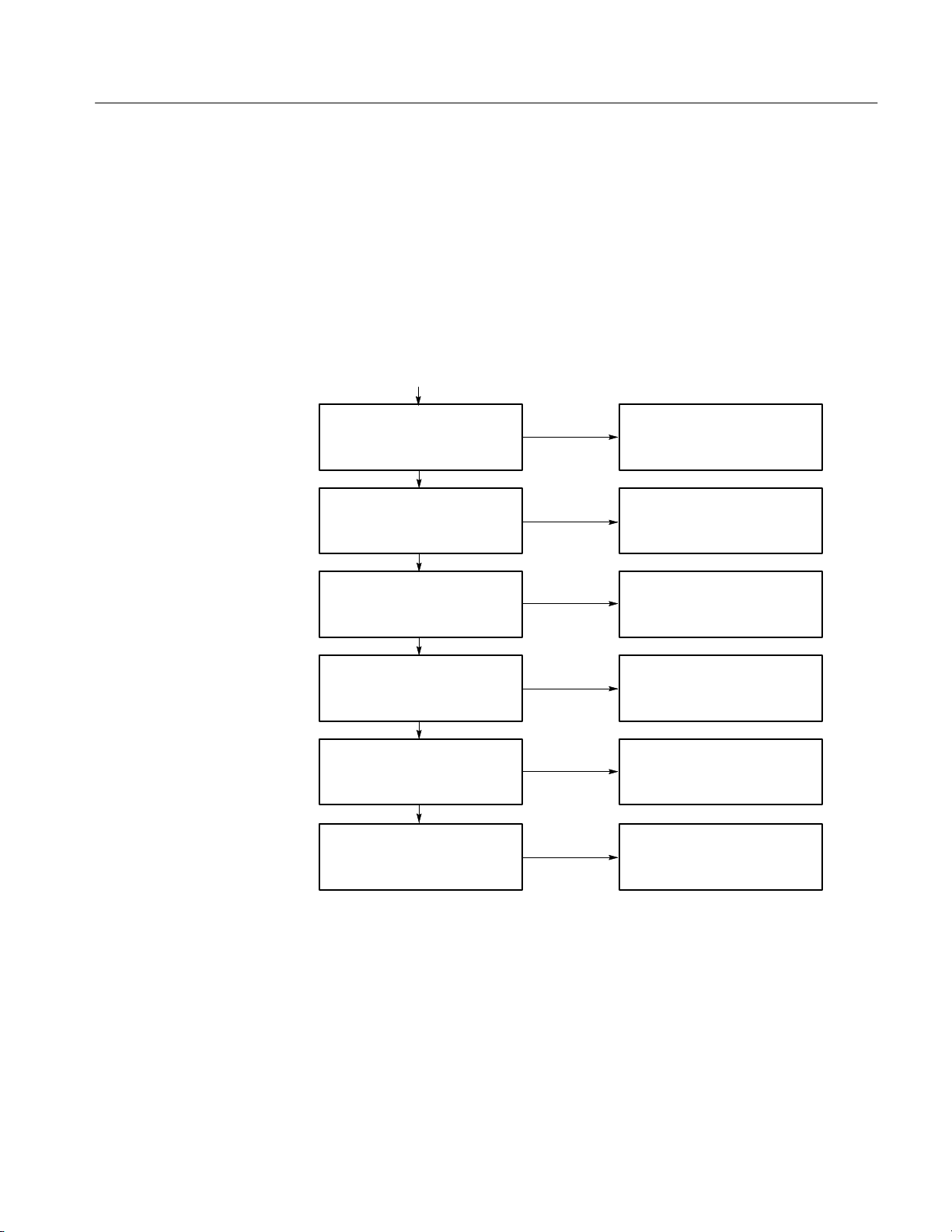
This section describes the structure of a transport stream starting with decoding.
The individual steps required for decoding a program are illustrated and the
relevant elements of the data stream required are explained. Figure 1–2 presents
an overview of the steps involved. The following subsections describe the
decoding steps. The most important syntax elements are given in Figure 1–4
through Figure 1–10 starting on page 1–11.
Procedure
Transport stream
synchronization
Read-out of transport stream
contents
Accessing a program
Descrambling, if required
Synchronization
of a program
Required elements
of the data stream
Sync Byte 0x47
Program Specific Information (PSI)
(PAT + PMTs)
Packet IDentification
(PID)
transport_scrambling_control,
Conditional Access Table
(CAT)
Program Clock Reference (PCR),
time stamps of elementary streams
(PTS + DTS)
Decoding additional data
Figure 1–2: Functions of a transport stream demultiplexer
MTD200 MPEG Test Decoder User Manual
Service Information (SI)
1–5
Page 21

Introduction to Digital TV Transmission Technique
Transport Stream
Synchronization and
Packet Identification
The transport stream as a multiplex stream has to receive data from different
elementary streams. The beginning of a new packet is marked by a sync byte
0x47. The packets of a transport stream have a fixed length of 188 bytes. The
value 0x47 is not exclusively reserved for the beginning of a packet. Thus, this
value does not always indicate a packet start.
To ensure stable synchronization, however, the repetitive occurrence of a sync
byte at 188-byte intervals must be checked. The hysteresis parameters define
how often the value 0x47 must occur at 188-byte intervals for the packet
synchronization to be considered locked or how often the sync byte must be
missing or the wrong for the packet synchronization to be declared lost.
The sync byte interval can also be 204 bytes (188 + 16 bytes). In this case, the
last 16 bytes originate from the channel coding (Reed-Solomon error protection).
Channel decoding has already taken place at the transport stream level so that the
16 bytes at the end of each packet do not carry any useful information. Only the
clock conversion from 204 to 188 bytes per packet duration has not been
performed.
A header with a length of four bytes precedes each transport stream packet. The
first byte of the header is the sync byte, as described above. If not all the bit
errors caused by transmission can be eliminated during channel decoding, the
Transport Error Indicator is set in the header of the packet concerned.
Contents of the Transport
Stream
Critical information for identifying a packet is the PID (Packet IDentification).
The PID is a field of 13 bits. It can thus have 8196 different values. A PID is
assigned to each substream such as a video or audio stream (not to a program).
Some PID values are fixed, such as value 0x000 for the PAT (see Contents of the
Transport Stream on page 1–6), value 0x0001 for the CAT (see Descrambling
on page 1–8), and value 0x1FFF for the so-called zero packets that do not
contain useful data but only dummy bytes.
The transport stream normally contains several programs consisting of several
elementary streams. The contents of the transport stream is described in the
Program Specific Information (PSI). Each transport stream contains a Program
Association Table (PAT) as well as one or several Program Map Tables (PMTs).
The PAT is contained in the transport stream packets with the PID 0x0000. It
refers to all the programs contained in the transport stream. The PAT indicates
the program number and the corresponding PID for the Program Map
Table (PMT).
The elementary streams (vision, sound, data) that belong to the individual
programs are described in a PMT. A PMT consists of one or several sections,
each describing a program.
1–6
MTD200 MPEG Test Decoder User Manual
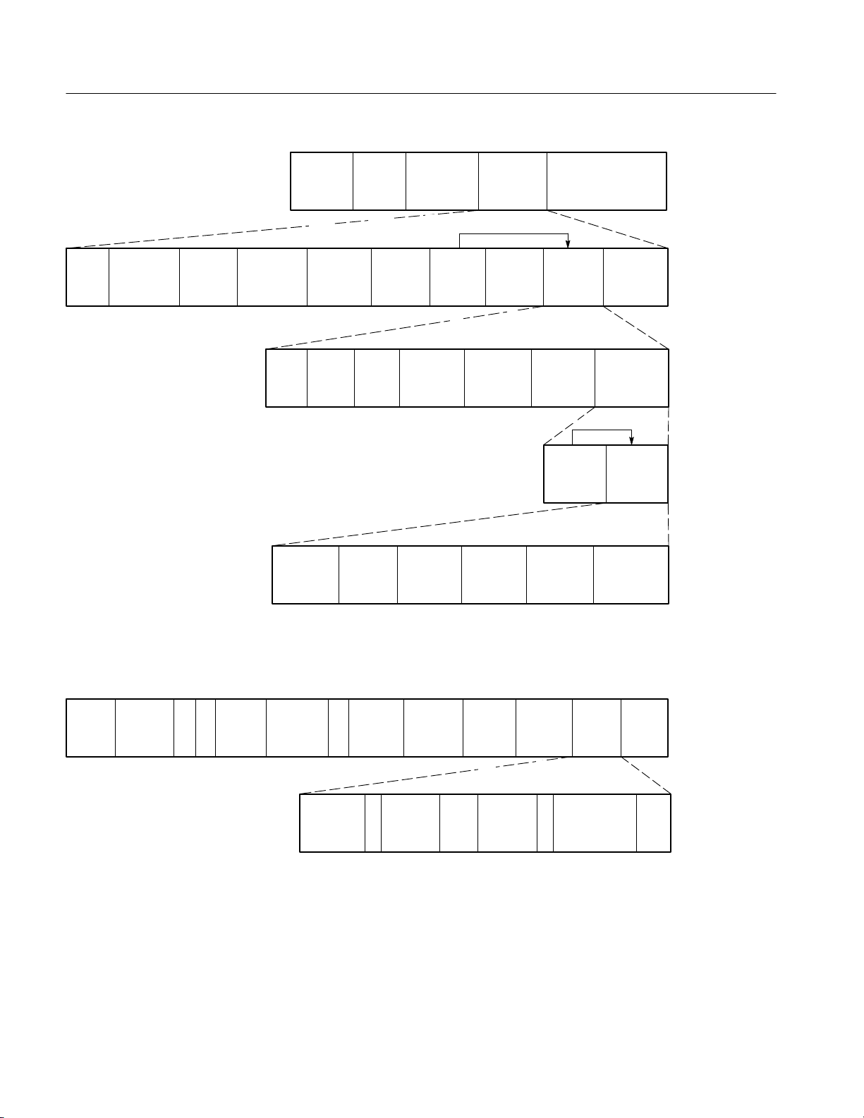
Page 22

Introduction to Digital TV Transmission Technique
TS
Header
TS Packet
PID 0x0000
Program
Association
Table
Program Number
program_map_PID
Program Number
program_map_PID
TS
Header
TS
Header
TS Packet
program_map_PID
Program
Map
Table
elementary_PID
elementary_PID
TS Packet
program_map_PID
Program
Map
Table
TS
Header
TS
Header
TS Packet
elementary_PID
Payload
elementary
stream
TS Packet
elementary_PID
Payload
elementary
stream
Access to a Program
elementary_PID
elementary_PID
Figure 1–3: PAT and PMT describe the contents of a transport stream
If the programs contain contending elementary streams, such as several audio
streams, a selection must be made. The packets of the selected elementary
streams identified by PID now must be conveyed from the demultiplexer to the
associated decoders.
Analyzing the Continuity Counter in the packet header permits checking whether
individual packets belonging to an elementary stream arrive completely and in
the correct order. The Continuity Counter is represented by the four least
significant bits of the last header bytes (bit 29 to bit 32 of each packet). The
value (0–15) is incremented with each new packet. Value 15 is followed by
a zero.
MTD200 MPEG Test Decoder User Manual
1–7
Page 23

Introduction to Digital TV Transmission Technique
Two exceptions are permissible:
The Discontinuity Indicator is set in the Adaptation Field (for example,
during a program step). See Figure 1–5 on page 1–11. The Continuity
Counter can then have any value.
A packet may be transferred twice. The Continuity Counter must not be
incremented.
Descrambling
The received data can be scrambled. Scrambling is performed at the level of the
transport stream (TS) or of the packetized elementary stream (PES).
The corresponding header information (PES header or TS header) remains
unscrambled. If scrambling is required at the transport stream level, this also
includes the PES header, whereas the TS headers remain unscrambled in all
cases.
If a packet (TS packet or PES packet) is scrambled, this is indicated by the first
bit of the scrambling control field of the associated header (TS header or PES
header). The second bit in the scrambling control field is required, since the
scrambling code changes from time to time. This bit is set if a new scrambling
code is valid for the packet in question.
To be able to perform descrambling, the decoder requires specific control data
that are transmitted with the entitlement control messages (ECM) and the
entitlement management messages (EMM). The ECM contain the scrambling
codes and the EMM distribute the access authorizations for the receivers. ECM
and EMM are included and referred to in the program specific information (CAT
or PMT).
Descrambling is performed in a supplier-specific hardware, which can be
connected to the decoder via a DVB-defined interface.
Program Synchronization
1–8
In general, a program comprises several elementary streams. A common clock
reference is required to synchronize the decoding and display (or output) of the
individual elementary streams. This clock reference for each program comes as
Program Clock Reference (PCR) and is carried along in an elementary stream of
the program. To this effect, every 40 ms at maximum, the 4-byte header of a
transport packet is extended by an Adaptation Field (see Figure 1–5 on
page 1–11) which contains not only a variety of other signaling information that
cannot be dealt with here, but also the PCR. The Adaptation Field is always
unscrambled.
The PCR value (42 bits long) corresponds to the state of a counter with a
27 MHz clock at the time of arrival of the first TS-packet byte containing the
PCR value. It is used in the decoder for controlling the 27 MHz system clock
PLL. Thus, the synchronization of the multiplexer at the transmitter end and of
the demultiplexer at the receiver end is ensured.
MTD200 MPEG Test Decoder User Manual
Page 24

Introduction to Digital TV Transmission Technique
The individual elementary streams contain time stamps, such as the Decoding
Time Stamps (DTS) and the Presentation Time Stamps (PTS), for synchronizing
the decoding and display of the individual elementary streams. The Packetized
Elementary streams (PES) are transmitted in packets with up to a length of
64 kBytes (more for video streams), which define a certain display length (e.g., a
picture in case of video streams). A header precedes each packet of an elementary stream (PES). The header also contains the DTS and PTS. If a transport
packet contains the beginning of a PES packet, the 10th bit (Payload Unit Start
Indicator) is set in the header of the transport packet.
The PTS / DTS value (33 bit) corresponds to the state of a 90 kHz counter and
refers to the 33 most significant bits of the PCR. The ratio of 27 MHz (PCR) to
90 kHz (PTS / DTS) is 300 and is attained by the fact that the 9 least significant
bits of PCR only count to 300 (instead of 512).
Two different time stamps (DTS and PTS) are provided, since the order of arrival
of the PES packets and their decoding does not always correspond to the order of
display (for instance during the transmission of difference pictures in video
streams). In many cases, only one PTS is available.
Service Information
The tables defined by the DVB project (see ETS 300 468) are to be seen as
service information. The information contained in these tables is not required for
decoding, but provides convenient access for the end user: it might be program
information for the viewer or control information for the decoder and units
connected to it.
In many cases, PSI (Program Specific Information) is also mentioned in
connection with SI (Service Information). PSI is already defined in MPEG-2 and
contains the above-mentioned tables PAT (Program Association Table), PMT
(Program Map Table), CAT (Conditional Access Table), and NIT (Network
Information Table). The latter contains data provided by the network operator for
tuning the receivers (for example, orbit positions or transponder numbers). The
CAT and NIT contents are specified by the DVB project (and not by MPEG).
Tables additionally defined by the DVB project are as follows:
BAT (Bouquet Association Table) contains information about the different
programs of a broadcaster irrespective of their propagation paths.
SDT (Service Description Table) describes the programs offered.
EIT (Event Information table) supplies the data base for an electronic TV
guide with information about the type of program and age classification for
the viewer.
RST (Running Status Table) contains status information about the individual
programs and especially serves for controlling video recorders.
MTD200 MPEG Test Decoder User Manual
1–9
Page 25

Introduction to Digital TV Transmission Technique
TDT (Time and Date Table) provides information about date and current
time (UTC).
TOT (Time Offset Table) provides information about the local time offset in
addition to date and time.
ST (Stuffing Table) has no relevant contents. It is generated when invalid
tables are overwritten during transmission (for example, at cable headends).
The PIDs for the tables are predefined. The PMTs whose PIDs are defined in the
PAT are an exception. Each table has a table_id at the beginning of each table.
This table_id is required to transmit different tables with a single PID. The
interrelation of table type, PID and table_id is shown in Table 1–1.
T able 1–1: PID and Table_ID for PSI / SI
Table PID Table_ID
PAT 0x0000 0x00
PMT 0x0020 to 0x1FFE 0x02
CA T 0x0001 0x01
NIT 0x0010 0x40 to 0x41
BA T 0x0011 0x4A
SDT 0x0011 0x42, 0x46
EIT 0x0012 0x4E to 0x6F
RST 0x0013 0x71
TDT 0x0014 0x70
TOT 0x0014 0x73
ST 0x0010 to 0x0014 0x72
1–10
MTD200 MPEG Test Decoder User Manual
Page 26

Syntax Diagrams
Transport packets
188 bytes
Introduction to Digital TV Transmission Technique
transport
priority
header
payload
PID transport
scrambling
control
header
sync
transport
byte
error
indicator
8 1 1 1 13 2 2 4
payload
payload
unit start
indicator
header
adaptation
field
control
Figure 1–4: Transport packet
adaptation
field
length
811
PCR
42 8 8 8
OPCR
42
discontinuity
indicator
splice
countdown
random
access
indicator
transport
private
data
length
elementary
stream
priority
indicator
1
transport
private
data
5 flags optional
5
adaptation
field
extension
length
fields
3 flags optional
payload
continuity
counter
3
adaptation
field
to Figure 1-5
stuffing
bytes
fields
ltw_valid
flag
1
Figure 1–5: Adaptation field
MTD200 MPEG Test Decoder User Manual
ltw
offset
15 2
piecewise
rate
22 33
splice
type
4
DTS_next_au
1–11
Page 27
Introduction to Digital TV Transmission Technique
packet
start
code
prefix
’10’
scrambling
control
211
2 m*8
PES
priority
data
alignment
indicator
copyright original
ESCR
PTS
DTS
33
33
PES
private
data
128 8 16 7
stream
id
1
ES
rate
42
pack
header
field
8
PES
packet
length
824 16
7 flagsPES
or copy
1
DMS trick
mode
22 8 7
program
packer
seq cntr
optional
PES
HEADER
8 8
additional
copy info
P-STD
buffer
PES
header
data
length
PES packet data bytes
optional
fields
previous
PES
CRC
16
5 flags
PES
extension
field
length
PES
extension
PES
extension
field data
stuffing
bytes
(0xFF)
optional
fields
Figure 1–6: PES header
table
id
section
syntax
indicator
81 16
’0’
1 12
section
length
2
transport
stream
id
program
number 0
Figure 1–7: Program association section
1–12
version
number
2
16 16
current
next
indicator
5 32
network
PID
813
section
number
1
progrm
... ...
number i
last
section
number
88
313
N
loop
program
map
PID_i
CRC
32
MTD200 MPEG Test Decoder User Manual
Page 28

Introduction to Digital TV Transmission Technique
table
section
id
syntax
indicator
81 16
1 12
section
’0’
length
2
program
number
2
Figure 1–8: Program map section
table
section
id
syntax
indicator
81 16
1 12
section
’0’
length
2
Figure 1–9: Conditional access section
version
number
version
number
5 8 32
current
next
indicator
5 8 13
current
next
indicator
1
section
number
1
section
number
last
section
number
8 4
last
section
number
8
PCR
PID
stream
type
812
N
loop
descriptors
program
info
length
elementary
PID
3
CRC
32
N loop
descriptorsNloop
ES info
length
413
CRC_32
32
N
loop
descriptors
table
section
id
syntax
indicator
81
table
id
extensions
private
indicator
1122
N private data bytes
version
number
16 1
288
532
Figure 1–10: Private section
private
section
length
current
next
indicator
section
number
last
section
number
N
private
data
CRC
32
MTD200 MPEG Test Decoder User Manual
1–13
Page 29

Introduction to Digital TV Transmission Technique
1–14
MTD200 MPEG Test Decoder User Manual
Page 30

Page 31

Measurement Functions
In this section you will find a comprehensive description of all measurement
functions and error LEDs provided on the MTD200 MPEG Test Decoder to
monitor an MPEG-2 transport stream. These measurement functions fully
comply with the DVB guidelines for monitoring MPEG-2 transport stream
syntax (DVB Measurement Guidelines ETR 290). Moreover, the MPEG test
decoder calculates the total transport stream data rate as well as the data rates of
all programs contained in the transport stream and their elementary streams.
There are ten LEDs on the front panel for displaying detected transport stream
errors. A liquid crystal display (LCD) on the front panel and an on screen display
(OSD) on an external video screen are also available for more informative error
indication. The OSD information is overlaid on the decoded video signal at the
video outputs as a measurement window (refer to On Screen Display (OSD) on
page 4–32). All information on the display of the measurement parameters given
in this section apply to the LCD as well as to the OSD.
MTD200 MPEG Test Decoder User Manual
2–1
Page 32

Measurement Functions
Elements of Transport Stream Syntax
Figure 2–1 shows an overview of the basic structure of a transport stream.
Elements of the transport stream syntax that are relevant for monitoring, such as
packet header, adaptation field or PES (Packetized Elementary Stream) header,
are shown in detail.
PTS
value
“10” PES
Optional
pointer
field
1 Byte
Transport stream
Header Payload Header Payload
Sync
Transport
byte
error
indicator
1 Byte 1 Bit 1 Bit 1 Bit 13 Bit 2 Bit 2 Bit 4 Bit
Payload
unit start
indicator
Transport
priority
Header Payload: PES
4 Byte
Transport
PID
scramble
control
DTS
value
33 Bit
33 Bit 42 Bit 22 Bit 8 Bit 7 Bit 16 Bit
scrambling
control
Packet
startcode
Iprefix
Adaption
field
(optional)
Adaption
field
control
ESCR ES
2 Bit
Stream ID Optional
1 Byte24 Bit
PES
header
Continuity
counter
rate
11 flagsPES
12 Bit
field
length
DSM
trick
mode
Optional
header
data
length
1 Byte2 Bit
PES
packet
length
16 Bit
ES-Start-Packet
1 Byte 1 Bit
fields
PES
header
Discontinuity
indicator
Additional
copy info
Previous
PES CRC
Stuffing
bytes
Random
access
indicator
1 Bit 1 Bit 5 Bit up to 182 Bytes
PES
extension
188 Byte
Elementary
stream
priority
indicator
FlagsAdaption
Optional
field
Suffing
bytes
Program
clock
reference
flag
1 Bit 1 Bit 1 Bit 1 Bit
Figure 2–1: Elements of the transport stream syntax
2–2
Org
program
clock ref
flag
1 Bit
Splicing
point
flag
Transport
private
data flag
Adaption
field
extension
flag
PCR
value
42 Bit
OPCR
value
42 Bit
Other
n Bit
MTD200 MPEG Test Decoder User Manual
Page 33

Overview of All Measurement Functions
Measureme
Priority
PID I
Trigger
The measurement functions of the MPEG test decoder fully comply with the
recommendations contained in the DVB Measurement Guidelines (ETR 290) for
the analysis of MPEG-2 transport stream syntax.
Table 2–1 shows an overview of all measurement functions of the MPEG test
decoder and information on error indication, either as a cumulative message
(LED) or as a detailed error message in the Monitoring Statistic or the Monitoring Report menu on the LCD or OSD. Refer to MONITORING / STATISTICS
Menu on page 4–12 and MONITORING / REPORT Menu on page 4–13.
In addition to the measurement functions shown in Table 2–1, the MPEG test
decoder also calculates the following values from the transport stream multiplex:
Total transport stream data rate [MBit/s]
Data rates of all individual programs in the TS multiplex [Mbit/s]
Data rates of all elementary streams of the individual programs in the TS
multiplex [Mbit/s]
Measurement Functions
Data rate for null packets
Data rate for PSI/SI table
NOTE. The data rates of programs and single streams calculated by the MTD200
are the gross rates of the programs and single streams. Packet headers and
possible adaptation fields are considered in the measured value.
The transport stream data rates measured are displayed on the LCD or OSD in
the DECODER / SELECT PROGRAM menu (see page 4–21).
T able 2–1: Overview of measurement functions
Error display
nt
TS_sync_loss 1 TS TS-Sync Loss
Sync_byte_error 1 SYNC Sync. Byte Single
PAT_error 1 PAT PAT Upper Distance
Continuity_count_error 1 COUNT Cont. Cnt. Packet Order
(ETR 290)
LED LCD / OSD Error condition
OK
Burst
Table ID
Scrambled
More Than Twice
Lost Packet
—
—
no
no
yes
yes
yes
yes
yes
yes
nfo
error?
yes
yes
yes
yes
no
yes
yes
yes
yes
yes
on
Error no.
(ETR 290)
1.1
1.2
1.3
1.4
MTD200 MPEG Test Decoder User Manual
2–3
Page 34

Measurement Functions
T able 2–1: Overview of measurement functions (cont.)
Priority
Priority
(ETR 290)
Measurement
Measurement
PMT_error 1 PMT PMT Upper Distance
PID_error 1 PID PID Missing yes no 1.6
Transport_error 2 TRANS Transport yes yes 2.1
CRC_error 2 CRC CRC PAT
PCR_error
and
PCR_accuracy_error22
PTS_error 2 OTHER PTS yes no 2.5
CA T_error 2 OTHER CAT Table ID
SI_repetition_error 3 OTHER SI REP. PAT Upp/Low Dist.
NIT_error 3 OTHER NIT T able ID
SDT_error 3 OTHER SDT Table ID
EIT_error 3 OTHER EIT Table ID
RST_error 3 OTHER RST Table ID yes yes 3.7
TDT_error 3 OTHER TDT Table ID
unreferenced_PID 3 OTHER Unref. PID yes yes 3.4
(ETR 290)
Error display
Scrambled
CA T
PMT
NIT
EIT
BA T
SDT
TOT
OTHER PCR Discontinuity
Upper Distance
Missing
CA T Upp/Low Dist.
PMT Upp/Low Dist.
NIT Upp/Low Dist.
SDT Upp/Low Dist.
BA T Upp/Low Dist.
EIT Upp/Low Dist.
RST Upp Dist.
TDT Upp/Low Dist.
TOT Upp/Low Dist.
NIT Upper Dist.
SDT Upper Dist.
EIT Upper Dist.
TDT Upper Dist.
PID Info
PID InfoError conditionLCD / OSDLED
yes
yes
yes
yes
yes
yes
yes
yes
yes
yes
yes
yes
yes
yes
yes
yes
yes
yes
yes
yes
yes
yes
yes
yes
yes
yes
yes
yes
yes
yes
yes
yes
yes
Trigger on
Trigger on
error?
error?
no
yes
yes
yes
yes
yes
yes
yes
yes
yes
yes
no
no
yes
yes
no
no
no
no
no
no
no
no
no
no
yes
no
yes
no
yes
no
yes
no
Error no.
Error no.
(ETR 290)
(ETR 290)
1.5
2.2
2.3
and
2.4
2.6
3.2
3.1
3.5
3.6
3.8
2–4
MTD200 MPEG Test Decoder User Manual
Page 35

TS_Sync_Loss (1st priority)
Each packet of the transport stream is preceded by a header consisting of four
bytes. The first byte of the header is the synchronization byte (SyncByte), whose
content is always the hexadecimal value 0x47. In the MPEG-2 decoder, the
SyncByte serves for synchronization with the packetized transport stream. DVB
recommendations define synchronism such that a sequence of at least five
SyncBytes has to be detected by the MPEG-2 decoder. Synchronism is lost if the
SyncBytes in a sequence of at least three TS packets are not detected according
to the DVB recommendations. This status is referred to as TS_Sync_Loss. The
synchronization hysteresis of 5/3 SyncBytes recommended in the DVB
guidelines is also a basic setting in the MPEG test decoder, although it may be
modified for synchronization tests (refer to TS INPUT / SYNC CONDITION
Menu on page 4–28).
In the DVB Measurement Guidelines (ETR290), the preconditions for a
TS_Sync_Loss message are set as follows:
Measurement Functions
TS_Sync_Loss is signaled if
the content of the synchronization bytes in a sequence of three TS packets does not equal
0×47 (hexadecimal)
Two LEDs labeled TS and located one above the other at the very left of the
front panel serve to display the synchronization status. An error (no synchronism) is indicated by the yellow LED (top); synchronism is indicated by the
green LED (bottom) lighting.
MTD200 MPEG Test Decoder User Manual
2–5
Page 36

Measurement Functions
Sync_byte_error (1st priority)
Each packet of the transport stream is preceded by a header consisting of four
bytes. The first byte of the header is the synchronization byte (SyncByte), whose
content is always the hexadecimal value 0x47. In the MPEG-2 decoder the
SyncByte serves for synchronization with the packetized transport stream. If the
SyncByte is missing or contains errors too often, the decoder will not be able to
synchronize to the transport stream.
The MPEG test decoder checks the SyncByte of every packet in the transport
stream for correct contents.
In the DVB Measurement Guidelines (ETR290), the preconditions for a
SyncByte_Error message are set as follows:
SyncByte ERROR is signaled if
the content of the synchronization byte in the TS header does not equal 0x47 (hexade-
cimal)
An error of this type is indicated by the LED labeled SYNC lighting (line of
LEDs at front panel). Additional information on the fault triggering the
SyncByte error message (SINGLE = single error or BURST = Burst error) can
be obtained from the monitoring report.
2–6
MTD200 MPEG Test Decoder User Manual
Page 37

PAT_error (1st priority)
Measurement Functions
The Program Association Table (PAT) contains a list of all programs and PIDs
contained in the transport stream and of associated PMTs (Program Map Tables),
which contain detailed program descriptions. The PAT is of key importance for
decoding TV and audio programs. If the PAT is not available or contains an
error, the MPEG-2 decoder will not be able to select and decode a program from
the transport stream multiplex.
The syntactic structure of a PAT is comprehensively defined in MPEG-2 systems
(ISO/IEC 13818–1). The PAT is exclusively transmitted in packets with 0x0000
as PID. The table may be divided into a maximum of 256 sections with the table
index (table_id) of each section being 0x00.
In the DVB Measurement Guidelines (ETR290), the preconditions for a
PAT_Error message are set as follows (abbreviated designations in parentheses
are the text displayed in the monitoring report):
PAT ERROR is signaled if
PAT table index does not equal 0x00 (TABLE ID) or
PAT is transmitted in encrypted form (SCRAMBLED) or
PAT is not transmitted at least every 0.5 second (UPPER DISTANCE)
An error of this type (cumulative message) is indicated by the LED labeled PAT
lighting (line of LEDs at front panel). Detailed information on the type of PAT
error as defined in the above table can be obtained from the monitoring report.
MTD200 MPEG Test Decoder User Manual
2–7
Page 38

Measurement Functions
PMT_error (1st priority)
The PMT (Program Map Table) is a table for detailed program descriptions
referenced in the PAT. As essential information for the MPEG-2 decoder, it
contains the PIDs of all packets of the individual TV, audio, and data streams
(elementary-stream PIDs) as well as the PIDs of packets serving for the
transmission of PCR values associated with the program. Like the PAT, the PMT
is of key importance for decoding TV and audio programs. If PMT is not
available or contains an error, the MPEG-2 decoder will not be able to select and
decode a program from the transport stream multiplex.
The syntactic structure of a PMT is defined in MPEG-2 systems (ISO/IEC
13818-1). In contrast to the PAT, the PIDs of the individual PMTs are variable;
MPEG-2 permits values ranging from 0x0010 to 0x1 FFE (compare to DVB
ETS 300468: 0x0020 to 0x1 FFE). The table may be divided into a maximum of
256 sections with one section for each program. The table index (table_id) of
each section must be 0x02.
In the DVB Measurement Guidelines (ETR290), the preconditions for a
PMT_Error message are set as follows (abbreviated designations in parentheses
are as text displayed in the monitoring report):
PMT ERROR is signaled if
PMT table index does not equal 0x02 (TABLE ID) or
PMT is transmitted in encrypted form (SCRAMBLED) or
PMT is not transmitted at least every 0.5 second (UPPER DISTANCE)
An error of this type (cumulative message) is indicated by the LED labeled PMT
lighting (line of LEDs at front panel). Detailed information on the type of PMT
error as defined in the above table can be obtained from the monitoring report.
2–8
MTD200 MPEG Test Decoder User Manual
Page 39

Continuity_count_error (1st priority)
Each packet of the transport stream is preceded by a header consisting of four
bytes. The fourth byte of the header contains the count of a four-bit continuity
counter. The count must be increased by one for every packet of the transport
stream that has the same PID. The count may consist of values ranging from 0 to
15; beyond 15, it will start from 0 again (modulo-16 counter). The continuity
counter serves to recognize packets of a TV or audio program that are either
missing or repeated more than once.
The MPEG-2 standard also tolerates counter discontinuity, provided this is
indicated by a discontinuity indicator in the optional adaptation field (AF) of the
same packet. This method is primarily used for the suppression of error messages
when changing programs preceded by remultiplexing of the transport stream.
In the case of null packets (packets that do not contain any useful data but have a
PID of 0x1FFF), continuity is not checked, since the value of the continuity
counter in zero packets is not defined in the MPEG-2 standard.
In the DVB Measurement Guidelines (ETR 290), the preconditions for a
Continuity_Count_Error message are set as follows (abbreviated designations in
parentheses are the text displayed in the monitoring report):
Measurement Functions
Continuity Count ERROR is signaled if
the same packet has been transmitted more than twice without discontinuity indicator or
(MORE THAN TWICE)
a packet is missing, (new count = old count + 2 without discontinuity indicator or
(LOST PACKET))
there is a wrong sequence of packets (discontinuity without discontinuity indicator, without
any of the above conditions present (PACKET ORDER))
An error of this type (cumulative fault) is indicated by the LED labeled CONT
lighting (line of LEDs at front panel). More detailed information on the type of
Continuity_Count Errors as listed in the above table can be obtained from the
monitoring report.
MTD200 MPEG Test Decoder User Manual
2–9
Page 40

Measurement Functions
PID_error (1st priority)
The PMT (Program Map Table) entries reveal the elementary-stream PIDs that
are contained in the transport-stream multiplex. To decode a program with the
corresponding PID, these packets must be contained in the transport stream, and
for the MPEG-2 decoder to function error-free these packets also need to be
transmitted at certain intervals. The DVB Measurement Guidelines (ETR 290)
speak of a user specified period, which means that it can be freely selected by the
user. The preset value for the MPEG test decoder is 0.5 s, but it can be modified
in the MONITORING / LIMITS menu according to individual requirements
(refer to MONITORING / LIMITS Menu on page 4–15).
In the DVB Measurement Guidelines (ETR 290), the preconditions for a
PID_Error message are set as follows:
PID ERROR is signaled if
the interval between two elementary-stream packets of the same PID is > 0.5 seconds
An error of this type (cumulative message) is indicated by the LED labeled PID
lighting (line of LEDs at front panel). More detailed information on the type of
PID error as listed in the above table can be obtained from the monitoring report.
2–10
MTD200 MPEG Test Decoder User Manual
Page 41

Transport_error (2nd priority)
The second byte of every packet header in the transport stream contains the
transport_error_indicator, which is a flag that serves to indicate bit errors in the
following packet. This flag is generated and inserted by the Viterbi or Reed-Solomon decoder at the receiver end if the decoder is no longer capable of correcting all bit and byte errors in the transport stream.
Because it is not possible in case of a set transport_error_indicator to predict
which bit or byte contains an error, this packet must not be evaluated by an
MPEG-2 decoder. For this reason, the MPEG test decoder only indicates the
Transport_Error, which means that the packet is not checked for further transport
stream errors.
In the DVB Measurement Guidelines (ETR 290) the preconditions for a
Transport_Error message are set as follows:
Transport ERROR is signaled if
a transport_error_indicator bit is set in the packet header
Measurement Functions
An error of this type (cumulative message) is indicated by the LED labeled
TRANS lighting (line of LEDs at the front panel). As additional information, the
PID of the packet containing the error can be obtained from the monitoring
report.
NOTE. The PID information contained in the monitoring report may be wrong if
a transport error is indicated and if the bit error concerns the PID information
of the packet header.
MTD200 MPEG Test Decoder User Manual
2–11
Page 42

Measurement Functions
CRC_error (2nd priority)
If program-specific information (PSI tables), such as PAT, CAT, PMT, NIT, EIT,
SDT, BAT and TOT, is transmitted, a value for checking the check sum of this
section is inserted at the end of each table section. The so-called CRC (C
R
edundancy Check) is used for calculating the check sum at the transmitter and
receiver end. Combined with the additionally transmitted CRC value, the check
sum for each table section must be zero.
If the resulting check sum does not equal zero, the MPEG-2 decoder must reject
the information contained in this table.
If a CRC_error is detected, it cannot be predicted which part of the information
contained in the table is not correct. In this case, the MPEG test decoder signals
the CRC_error, but the transport stream is not checked for further errors which
are derived from the faulty content of this table (for example, a search for PMT
PIDs from a PAT or ES PIDs from a PMT).
In the DVB Measurement Guidelines (ETR 290), the preconditions for a
CRC_Error message are set as follows:
yclic
CRC ERROR is signaled if
a packet with PAT, CAT, PMT, NIT, EIT, BAT, SDT or TOT and CR check of a section does
not equal zero
An error of this type (cumulative message) is indicated by the LED labeled CRC
lighting (line of LEDs at front panel). As additional information, the PID of the
packet containing the error can be obtained from the monitoring report.
2–12
MTD200 MPEG Test Decoder User Manual
Page 43

PCR_error, PCR_accuracy_error (2nd priority)
In every transport stream, coded time values obtained from the system time are
transmitted to enable the MPEG-2 decoder to link its own timing to the system
timing of the coder to allow decoding (PLL). Each program contained in the
transport stream may have its own independent program system timing
(referenced in PMT). The program map table (PMT) reveals for all programs
contained in the transport stream in which packets (PIDs) the PCR (P
Cl
ock Reference) values are transmitted.
PCR values are transferred in the optional Adaptation Field with a width of 42
bits. The 42 bits contain two parts: a PCR base with 33 bits and the PCR
extension with 9 bits. The following formulae hold for the bit structure :
Measurement Functions
rogram
PCR base (i) = ( system clock frequency * t(i) DIV 300 ) % 2
33
PCR extension (i) = ( system clock frequency * t(i) DIV 1 ) % 300
PCR (i) = ( PCR base (i) * 300 ) + PCR extension (i)
A 42-bit PCR value coded this way starts again from count 0 after the elapse of
33
* 300 clocks (corresponds to a time period of approximately 26.5 hours at
2
27 MHz).
The MPEG-2 standard also tolerates discontinuity of PCR values following one
another, provided this is indicated by the discontinuity indicator in the optional
adaptation field (AF) of the same packet. This method is primarily used for the
suppression of PCR error messages when changing programs preceded by
remultiplexing of the transport stream.
In the DVB Measurement Guidelines (ETR 290) the preconditions for a
PCR_Error message are set as follows (abbreviated designations in parentheses
are the text displayed in the monitoring report):
PCR ERROR is signaled if
the difference of two consecutive PCR values of a program is > 100 ms and no
discontinuity is indicated in the optional adaptation field (DISCONTINUITY) or
the interval between two packets with PCR values of a program is > 40 ms
(UPPER DISTANCE)
The above mentioned intervals are given in the DVB Measurement Guidelines
(ETR 290) and are preset in the MPEG test decoder, but they can also be
modified according to individual requirements in the MONITORING / LIMITS
menu (refer to MONITORING / LIMITS Menu on page 4–15).
MTD200 MPEG Test Decoder User Manual
2–13
Page 44

Measurement Functions
The DVB Measurement Guidelines also recommend additional monitoring of the
accuracy of the PCR values transmitted. Accuracy of PCR values may be
impaired by inaccurate calculation of the 42-bit PCR word width or by errors
during modification of PCR values in a remultiplex.
NOTE. The term accuracy in this case does not refer to absolute frequency
accuracy of the 27 MHz system timing, but to the fluctuation width of the PCR
values of a program, which is caused by the above mentioned errors.
The MPEG-2 standard (ISO/IEC 13818–1) as well as the DVB Measurement
Guidelines (ETR 290) prescribe a maximum tolerance of ± 500 ns for PCR
values. The MPEG-2 standard (ISO/IEC 13818–4) also describes a method to be
used for testing the so-called timing accuracy, which serves to monitor the
compliance of these PCR tolerances. The description of this method contains an
inequation, which must be fulfilled for all PCR values of a program. This
inequation is as follows:
(i–i”–1)
PCR(i)–PCR(i”) )
v k v
(
i–i” ) 1
PCR(i)–PCR(i”)–
)
i being index of the byte in which the current PCR value was
transmitted
i’’ being index of the byte in which the previous PCR value was
transmitted
d being 27 + 810 * (PCR(i)–PCR(i’’)) / 27E6;
If the above inequation is not fulfilled for any consecutive two pairs of PCR
values, (maximum value of the left side and minimum values of the right side are
stored) the precondition for a PCR_accuracy_error is fulfilled.
PCR Accuracy ERROR is signaled if
the PCR tolerance within a program is > ± 500 ns
A PCR_error and a PCR_accuracy_error are indicated in a cumulative message
signaling several single errors by the LED labeled OTHER lighting (line of
LEDs at front panel). More detailed information on the type of PCR error as
listed in the above tables can be obtained from the monitoring report.
2–14
MTD200 MPEG Test Decoder User Manual
Page 45

PTS_error (2nd priority)
Measurement Functions
Presentation Time Stamps (PTS values) in the PES headers are transmitted by
transport stream packets of a program. They enable the MPEG-2 decoder to
identify the exact time when a transmitted data block (TV picture for video
streams and beginning of an audio sequence for audio streams) is to be presented. The time stamps are transmitted with a word width of 33 bits and relate to
the 27 MHz system timing sequence transmitted in the transport stream together
with the PCR values.
In the DVB Measurement Guidelines (ETR 290), the preconditions for a
PTS_Error message are set as follows:
PTS ERROR is signaled if
magnitude of the difference of two consecutive PTS values following one another is > 700
ms
The above mentioned interval is given in the DVB Measurement Guidelines
(ETR 290) and is preset in the MPEG test decoder, but it can also be modified
according to individual requirements in the MONITORING / LIMITS menu
(refer to MONITORING / LIMITS Menu on page 4–15).
An error of this type is indicated in a cumulative message signaling several
single errors by the LED labeled OTHER lighting (line of LEDs at front panel).
As additional information, the PID of the program containing the faulty PTS
values can be obtained from the monitoring report.
MTD200 MPEG Test Decoder User Manual
2–15
Page 46

Measurement Functions
CAT_error (2nd priority)
If encrypted data are contained in a packet of the transport stream, this must be
indicated in the packet header (2nd byte) within the field that is two bits wide
and is labeled transport_scrambling_control. The individual values indicate the
following:
Value (binary) Description
00 No encrypted data contained in the
packet
01, 10, 11 Defined by user
If encrypted data are to be transmitted, the MPEG-2 standard recommends the
additional transmission of the tables containing the encryption data (Conditional
Access Table, CAT) in separate packets with (0x0001) as PID and 0x01 as table
index.
The MPEG-2 standard prescribes that packet header including the optional
adaptation fields must not be transmitted in encrypted form. According to DVB
specifications (ETS 300 468), the same applies to tables containing service
information (SI tables PAT, PMT, NIT, EIT, BAT, TDT, TOT and SDT). The
only exception to this rule is the EIT (Event Information Table) when program
overviews are transmitted.
In the DVB Measurement Guidelines (ETR 290) the preconditions for a
CAT_Error message are set as follows (abbreviated designations in parentheses
are the text displayed in the monitoring report):
CA T ERROR is signaled if
a packet contains encrypted data, but no CAT is found (MISSING) or
a packet with CAT-PID (0x0001) is found, but table index does not equal
0x01 (TABLE ID)
An error of this type is indicated in a cumulative message indicating several
single errors by the LED labeled OTHER lighting (line of LEDs at front panel).
Additional information on the type of error as listed in the above table can be
obtained from the monitoring report.
2–16
MTD200 MPEG Test Decoder User Manual
Page 47

SI_repetition_error (3rd priority)
The DVB standard (ETR211) prescribes minimum and maximum intervals for
the repetition of individual packets and has complete tables containing service
information (SI). See Table 2–2. These values are preset in the MPEG test
decoder, but each value can be modified according to individual requirements in
the Monitoring/Limits menu. Refer to MONITORING / LIMITS Menu on
page 4–15.
T able 2–2: Repetition rates for service information according to DVB
Measurement Functions
Maximum interval
Service information
PAT 0.5 s 25 ms
CA T 0.5 s
PMT 0.5 s 25 ms
NIT 10 s 25 ms
SDT 2 s
BA T 10 s
EIT 2 s
RST — 25 ms
TDT 30 s 25 ms
TOT 30 s 25 ms
1
If present.
2
For current transport stream multiplex.
(complete table)
1
2
1
2
Minimum interval
(individual sections)
1
25 ms
25 ms
1
25 ms
25 ms
In the DVB Measurement Guidelines (ETS 300 468), the preconditions for a
SI_repetition_error are set as follows:
SI_repetition_error is signaled if
time difference between SI tables is too long (*** UPPER DIST ANCE) or
time difference between SI sections is too short (*** LOWER DIST ANCE)
The abbreviated designations in parentheses are the text displayed in the
monitoring report. The series of asterisks (***) is replaced by the abbreviation
used in the appropriate SI table (for example, NIT).
MTD200 MPEG Test Decoder User Manual
2–17
Page 48

Measurement Functions
An error of this type is indicated in a cumulative message signaling several
single errors by the LED labeled OTHER lighting (in the line of LEDs on the
front panel). Additional information on the PID of the table, in which a repetition
rate error was found, can be obtained from the monitoring report.
NIT, SDT, EIT, RST and TDT_error (3rd priority)
These types of service information (SI) are also inserted into the transport stream
as additional data (multiplex) and contain items such as the current date, time,
and description of the TV program. Each of these tables is transmitted in the
form of packets with a given packet number (PID) and must be contained in the
transport stream at certain intervals according to the DVB specification.
However, not every SI has a different PID; packets for TDT and TOT as well as
SDT and BAT have identical PIDs. These tables are differentiated by an entry in
the table header, the so-called table index (table_id). This table_id enables an
MPEG-2 decoder working in compliance with the DVB standard to identify the
type of service information with which it is dealing.
Table 2–3 gives an overview of the service information according to the DVB
guideline ETS 300 468.
T able 2–3: Overview of service information according to DVB guideline ETS
300468
Service Information PID [hex] Table_id [hex] Max. interval [sec]
NIT 0x0010 0x40, 0x41, 0x42 10
SDT 0x0011 0x42, 0x46 2
BA T 0x0011 0x4A 10
EIT 0x0012 0x4E to 0x4F,
0x50 to 0x6F
RST 0x0013 0x71 —
TDT 0x0014 0x70 30
TOT 0x0014 0x73 30
Stuffing Table 0x0010 to 0x0013 0x72 —
1
Only if present.
2
For the current transport stream multiplexer.
1
2
2
2–18
MTD200 MPEG Test Decoder User Manual
Page 49

Measurement Functions
In the DVB Measurement Guidelines (ETR 290), the preconditions for NIT_error, SDT_error, EIT_error, RST_error, or TDT_error messages are set as follows:
NIT_error, SDT_error, EIT_error, RST_error or TDT_error are signaled if
a packet with the PID of an SI packet NIT, SDT, EIT, RST, TDT or TOT, but or
wrong table index is contained in the transport stream (TABLE ID)
time difference between SI sections of NIT, SDT, EIT, TDT or TOT is too long
(*** UPPER DISTANCE)
The abbreviated designations in parentheses are the text displayed in the
monitoring report. The series of asterisks (***) is replaced by the abbreviation
used in the appropriate SI table (for example, NIT).
An error of this type is indicated in a cumulative message signaling several
single errors by the LED labeled OTHER lighting (in the line of LEDs at front
panel). As additional information, the table_id of the packet containing the error
or a possible repetition rate error can be obtained from the monitoring report.
MTD200 MPEG Test Decoder User Manual
2–19
Page 50

Measurement Functions
Unreferenced PID (3rd priority)
The Program Map Table (PMT) contains a complete list of all program
definitions contained in the transport stream. In turn, each program definition
contains the information on all PIDs of the elementary stream packets of this
program. This means that by evaluating the PMT one obtains the PIDs of all
transport stream packets which are permitted to convey the useful data of the
program. Besides these referenced packets, the transport stream multiplex is only
permitted to contain packets with program-specific information (PSI tables) such
as PAT, CAT, CA-PID, PMT, NIT, BAT, SDT, TDT, TOT, EIT, RST or having
packet numbers reserved by the MPEG-2 standard.
If the program is changed (a new PMT), a nonreferenced PID may be contained
in the transport stream during 0.5 s according to the DVB Measurement
Guidelines (ETR 290). This interval of 0.5 s is preset in the MPEG test decoder
to comply with DVB, but it can be modified according to individual requirements in the MONITORING / LIMITS menu (refer to MONITORING / LIMITS
Menu on page 4–15).
In the DVB Measurement Guidelines (ETR 290) the preconditions for an
Unreferenced_PID_Error message are set as follows:
Unreferenced PID ERROR is signaled if
the transport stream contains a packet with a PID which is not the PID of PAT, CAT,
CA-PID, PMT, NIT, BAT, SDT, TDT, TOT , EIT or RST and which is not referenced in a PMT
that is at least 0.5 second old (ES-PID or PCR-PID)
An error of this type is indicated in a cumulative message signaling several
single errors by the LED labeled OTHER lighting (line of LEDs at front panel).
As additional information, the PID of the packet containing the error can be
obtained from the monitoring report.
2–20
MTD200 MPEG Test Decoder User Manual
Page 51

Page 52

Preparation for Use
This section discusses general instructions on the preparation for use and the
operation of the MTD200 MPEG Test Decoder. It contains brief explanations of
the controls and connectors on the front and rear panels. This chapter also
provides step-by-step guidance to put the unit into operation.
Legend for Front and Rear View
The control elements of the unit are grouped together and color-coded according
to their respective functions. The individual groups of control elements are
described in Table 3–1 (front panel) on page 3–2 and Table 3–2 (rear panel) on
page 3–4.
MTD200 MPEG Test Decoder User Manual
3–1
Page 53

Preparation for Use
Front Panel
Front view of MTD200
T able 3–1: Legend for front view
Control/Connector Description
POWER
KEYP AD The keypad comprises four CURSOR keys, the ENTER and the
LC DISPLA Y Backlighted liquid crystal display (2 lines x 20 characters).
CCVS Analog video output. The decoded picture of a program in the MPEG
SND 1 / L, SND 2 / R Analog audio outputs. A sound signal of a program in the MPEG
After the unit has been connected to the AC supply and powered on,
the green LED lights signalling that the unit functions properly.
The red LED signals a defect. The unit must be powered off and
disconnected from AC supply to undergo repair.
Quick flashing of the red LED when the unit is powered on or off does
not indicate a defect.
ESCAPE key . The CURSOR keys are used to select the desired menu
item and for varying entered values. Pressing the ENTER key calls up
a submenu or confirms the entered value. ESCAPE is used to quit a
menu or to abort an entry procedure.
The green LED lights when a value can be varied (CURSOR keys) or
an entry made (ENTER).
transport stream is output. The output may be in PAL, SECAM or
NTSC (refer to DECODER/VIDEO OUTPUT Menu on page 4–25).
Depending on the instrument setting, measured data are inserted in the
picture (refer to SETUP/ON SCREEN DISPLAY Menu page 4–32.).
transport stream is output.
3–2
MTD200 MPEG Test Decoder User Manual
Page 54

T able 3–1: Legend for front view (cont.)
Control/Connector Description
TS ASI Input for an MPEG transport stream to DVB DOCUMENT A010:
TS PARALLEL Input for an MPEG transport stream to conforming to DVB DOC-
Preparation for Use
ASYNCHRONOUS SERIAL INTERFACE
Another input of this type is provided at the rear of the unit. If one of
the two inputs is selected, the respective LED lights.
UMENT A010: SYNCHRONOUS PARALLEL INTERFACE
If this input is selected, the LED is on.
ERROR INDICATION
The two TS LEDs indicate whether the instrument identifies an MPEG
transport stream at the selected input. The user-selectable hysteresis
parameters are decisive (refer to TS INPUT/SYNC CONDITION Menu
on page 4–28). If a transport stream is identified, the green LED
(bottom) lights up, otherwise the yellow LED (top) is on.
The other eight LEDs signal protocol errors in the transport stream in
line with ETR 290. The following errors are signaled:
SYNC Sync_byte_error
PAT PAT_error
CONT Continuity_count_error
PMT PMT_error
PID PID_error
TRANS Transport_error
CRC CRC_error
OTHER PCR_error, PCR_accuracy_error, PTS_error,
CA T_error , SI_repetition_error , NIT_error , SDT_error ,
EIT_error, RST_error, TDT_error,
unreferenced PID
The error messages are indicated at intervals of one second.
MTD200 MPEG Test Decoder User Manual
3–3
Page 55

Preparation for Use
Rear Panel
Rear view of MTD200
T able 3–2: Legend for rear view
Connector Description
POWER Power supply
RS 232 The serial interface is for remote control.
The attached flap may be used to prevent the power cable from
becoming disconnected.
Audio outputs In addition to the analog outputs L and R, a digital AES/EBU interface
is provided at the rear.
Video outputs The following outputs are available:
SER 75 : Digital serial interface to CCIR601
C : Chrominance signal, analog
Y : Luminance signal, analog
CCVS : CCVS signal, analog
Depending on the instrument setup, measured data may be inserted in
the picture (see SETUP/ONSCREEN DISPLAY Menu on page 4–32).
TS ASI Input for an MPEG transport stream to DVB DOCUMENT 010:
ASYNCHRONOUS SERIAL INTERFACE
When this input is selected, the front-panel LED marked TS ASI REAR
lights.
3–4
MTD200 MPEG Test Decoder User Manual
Page 56

Unpacking the Unit
Accessories
Preparation for Use
After unpacking the unit check that the equipment supplied is complete as listed
in Standard Accessories.
Check the unit carefully for any mechanical damage. If damage is found,
immediately inform the carrier in charge of the delivery. Keep the cardboard box
and the packing material in case you need to return the instrument.
The MTD200 MPEG Test Decoder is shipped with several standard accessories.
These accessories and any optional accessories are described below.
Standard Accessories
Optional Accessories
The following accessories are included with this product.
MTD200 MPEG Test Decoder
Power cable
Dual LEMO/dual XLR adapter cable
Null modem cable (RS-232)
Locking device (used to prevent the power cable from being disconnected)
This manual
You can order the following accessories for the MTD200 MPEG Test Decoder.
LEMO/open adapter cable (part number 2067.7415.00)
Dual LEMO/dual XLR cable (part number 2068.9187.00)
MTD200 MPEG Test Decoder User Manual
3–5
Page 57

Preparation for Use
Installation
CAUTION. To prevent damage to the instrument, ensure that the following
conditions are met prior to operating the MPEG test decode:
The earthing contact is connected to protective earth.
The ventilation openings are not obstructed.
The signal levels applied to the inputs are not above the permissible limits.
The outputs of the instrument are not overloaded or improperly connected.
Setting up the Unit
EMC Safety Precautions
Desktop Model. The measurement decoder is intended for indoor use. The
following site requirements must be met:
The ambient temperature should be between + 5 and + 45 °C.
The ventilation openings and the air outlet on top of the unit must be
unobstructed.
For use in the lab or on a desk, fold down the feet at the bottom of the unit.
Accommodation in a 19-inch Rack.
CAUTION. When mounting the unit in the rack, make sure that the air flow (air
inlet and outlet at perforations) is not obstructed.
To install a standard MPEG test decoder in a 19-inch rack, you can use Rack
Adapter (part number ZZA91 or Option 1R). Mounting instructions are supplied
with the adapter.
To avoid electromagnetic interference, the unit should be closed when in use.
Only suitable shielded signal and control cables may be used.
AC Supply Voltage
Connecting a Monitor
3–6
The MPEG test decoder can be operated on an AC supply from 100 to 240 V at
frequencies of 47 to 63 Hz. The power connector is located at the rear of the unit
(see Table 3–2 on page 3–4).
When a monitor is connected to one of the analog or digital video outputs, the
MPEG test decoder can display characteristics and errors of the applied transport
MTD200 MPEG Test Decoder User Manual
Page 58

Preparation for Use
stream clearly and in full detail. In this case, measurement results are displayed
in the decoded video picture by means of the OSD (on screen display) function.
If the MPEG test decoder is used as an operational decoder, the OSD function
can be switched off.
Fitting a Key Card
Programs or elementary streams of a transport stream can be encrypted. When a
key card valid for these programs is fitted in the unit, even encrypted programs
can be decoded. A precondition is, however, that the descrambling method
complies with DVB/TM1341. and that the key card has an interface compatible
with the common interface (CI). The key card has to be bought from the
broadcaster.
The data required for protocol analysis of a transport stream may not be
encrypted, but encrypted program contents will not impair the measurement
functions.
Open the unit to fit a key card.
Tools required Phillips screwdriver, size 0 and 2
CAUTION. The unit contains components that might be damaged by electrostatic
discharges. Therefore, adequate measures for EMC protection have to be taken
when work is carried out on the open unit.
1. Opening the unit:
a. Disconnect power plug.
b. Loosen four screws in feet at rear panel.
c. Remove feet.
d. Withdraw top plate of enclosure towards rear.
e. Undo four screws at corner of front panel and screw in front panel.
f. Withdraw decoder board towards front.
2. Inserting or replacing the key card (see Figure 3–1):
a. If a key card is fitted already, remove it by pressing the ejection lever on
the right.
b. Insert key card in the upper PCMCIA slot.
3. Closing the unit:
a. Proceed in the reverse order as for opening the unit.
MTD200 MPEG Test Decoder User Manual
3–7
Page 59

Preparation for Use
MPEG 2 decoder
Key card
Key card
ejection lever
Flash memory card
ejection lever
Figure 3–1: Slot for key card
Flash
memory card
3–8
MTD200 MPEG Test Decoder User Manual
Page 60

Preparation for Use
Setting the Level of
Analog Audio Outputs
The level is set with the aid of links on the MPEG decoder board.
The following output levels may be set:
+ 6 dBu
+ 9 dBu
+12 dBu
+15 dBu
The unit is factory-set to +6 dBu. To set another level the unit must be opened as
described in Fitting a Key Card on page 3–7. In addition, the upper screen
cover must be removed. To do so, loosen the 8 Phillips screws. The level can
now be set for both “left” and “right” by positioning the links as shown on the
screen cover (see Figure 3–2).
+6 dBu +9 dBu +12 dBu +15 dBu
Front Rear
Figure 3–2: Setting the audio level
MTD200 MPEG Test Decoder User Manual
3–9
Page 61

Preparation for Use
Á
Á
Function Test (Power-on Test)
The unit is powered on by pressing the POWER switch (see Power in Table 3–1
on page 3–2). The MPEG test decoder then performs a built-in test which is
completed after a few seconds. When the boot phase is started, all LEDs on the
front panel light up and a memory test is carried out. If a memory error occurs,
all LEDs will be blinking. If there is no error, the LEDs are switched off and the
boot phase is continued.
The individual steps of the boot phase are indicated by LEDs. The SYNC LED
corresponds to the least significant bit, the PAT LED to the next higher bit, etc. If
an error occurs during the boot phase, the current status indicated by the LED
will be retained (see Table 3–3). Otherwise, the instrument is set to the previously used instrument status and the status menu is displayed.
T able 3–3: LED-Codes during booting of equipment
LED-Code boot phase
0x01
Check Update
0x02
0x03
0x32
0x35, 0x36, 0x37
0x38
БББББББ
0x39
0x3A
0x3B
0x3C
0x3D
0x3F
Loading of main program
Starting of main program
Reset of MPEG-2-Chipset
Setting-up loading of MPEG-2-Demultiplexer
Loading of MPEG-2-Audio Decoder
ББББББББББББББ
Loading of MPEG-2-Video Decoder
Loading of Video-DAC
Starting of MPEG-2-Demultiplexer and MPEG-2-Video Decoder
Setting-up of ON Screen Display function
Loading of FPGA for protocol analysis
Loading of DSP for protocol analysis
The green LEDs next to the front-panel inputs indicate at which input the
instrument expects a signal. See Error Indication in Table 3–1 on page 3–3. If a
valid MPEG-2 signal is applied to the respective input, the instrument must
synchronize to it. When synchronization is completed, the lower (below TS)
green LED lights.
3–10
MTD200 MPEG Test Decoder User Manual
Page 62

Page 63

Manual Operation
This section describes the main operating functions of the MTD200 MPEG Test
Decoder and familiarizes the user with the operation of the instrument.
When powered on for the first time, the new instrument is in a factory-set default
state. Each change of instrument settings is permanently stored (even after
instrument power-off) and available when the unit is powered on again.
Control Elements
This section describes the parts of the MTD200 that are used to control the
instrument. A typical configuration is shown in Figure 4–1.
SER 75, Y, C or CCVS output
MTD200 (rear view)
AC
line in
Figure 4–1: Overview of control elements
MTD200 (front view)
CCVS output
Video Monitor
MTD200 MPEG Test Decoder User Manual
4–1
Page 64

Manual Operation
Keypad
Manual operation is performed by means of keys. See Figure 4–1 for the
locations of the keys. Figure 4–2 shows the keypad itself.
Figure 4–2: Keypad
The functions of the keys are as follows:
ESC Use the ESCAPE key to quit a submenu
ENTER Use the ENTER key to do one of the following:
H Call a submenu
H Start an entry
H Confirm an entry
LC Display
LED The yellow LED lights when a parameter can be varied using the
cursor keys, a selection can be made using ENTER, or a value
can be entered using ENTER.
y b a ' Use the cursor keys to select the desired menu item and to vary
values to be entered.
Operating steps and measurement results are displayed on a two-line liquid
crystal display (LCD) with 20 characters per line. Depending on the entry and
selection mode in use, the cursor is displayed in different ways (refer to Basic
Operating Procedures on page 4–4).
‘ ’ indicates a 1-out-of-N selection
Menu name
‘ ’ indicates an active setting
Figure 4–3: LC display
4–2
MTD200 MPEG Test Decoder User Manual
Page 65

Manual Operation
On Screen Display (OSD)
In addition to the information displayed on the LCD, a large menu picture (see
Figure 4–4) is inserted into the decoded video signal and displayed on an
external monitor. The menu in this on screen display (OSD) is displayed in
parallel with the information in the LCD. In addition to the different cursor
characters used (see Basic Operating Procedures on page 4–4), the cursor-se-
lected menu item or field in the OSD is in reverse video.
Status line top:
Menu name
Status line bottom:
Indicates key
Cursor
assignment
Figure 4–4: On screen display
MTD200 MPEG Test Decoder User Manual
4–3
Page 66

Manual Operation
Basic Operating Procedures
In this section, commonly used basic operating procedures are described. In the
subsequent menu descriptions, these procedures are assumed to be known. In the
menu descriptions, only operating procedures differing from basic operations
will be explained.
Menu Selection
Menu selection is used to call up submenus in the MAIN menu. The possibility
for a selection is indicated by the character ‘ → ’. The cursor ‘ ← ’ is set to the
desired menu with the aid of the cursor keys (y b a ' ). The selected menu is
called up with ENTER.
y b a '
Enter Calls up the submenu
ESC Returns to next higher menu
Cursor for menu selection
Set cursor to desired submenu
DECODER submenu
Figure 4–5: Menu selection
4–4
MTD200 MPEG Test Decoder User Manual
Page 67

Manual Operation
1-out-of-N Selection
The 1-out-of-N selection is used to switch the transport stream inputs in the TS
INPUT/ROUTE menu. The user may select a setting from a list of N items. The
selection mode is identified by the character → . Selection is made by moving
the cursor → to the desired item (for example, PARALLEL) using the cursor
keys y b a ' . The selected setting is activated with ENTER. In the LCD,
active settings are marked with an asterisk (*).
y b a '
ENTER Activates the selected setting which is marked with an asterisk (*)
ESC Returns to the next higher menu
Cursor for 1-out-of-N selection
Set cursor to desired item
IRNOPUUTT
E*PSAERR.IALFFRROONNTT
Active setting
Figure 4–6: 1-out-of-N selection
MTD200 MPEG Test Decoder User Manual
4–5
Page 68
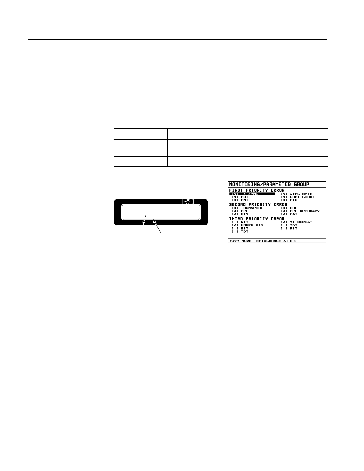
Manual Operation
M-out-of-N Selection
The M-out-of-N selection is explained using the MONITORING/PARAMETER
GROUP menu as an example. The user may activate several items in a list of N
items. The selection mode is identified by the cursor character →. Using the
cursor keys (y b a '), the cursor → is set to the item to be changed (for
example, TS_SYNC). The setting status is switched with ENTER (ON → OFF
or OFF → ON). An active setting is marked with [X] (ON); an inactive setting is
marked with [ ] (OFF).
y b a '
ENTER Switches the status of the selected item. Active items are marked with
ESC Returns to next higher menu.
Set cursor to desired item.
[X] for (ON); inactive items are marked with [ ] for (OFF).
Cursor for
M-out-of-N
selection
Identifies an
active setting
Figure 4–7: M-out-of-N selection
4–6
MTD200 MPEG Test Decoder User Manual
Page 69
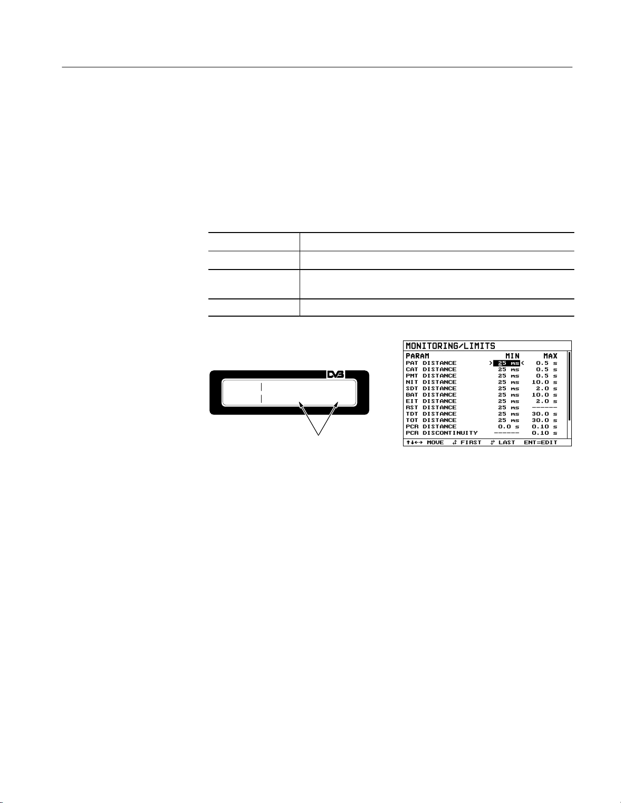
Manual Operation
Entering Numerals
Numeric values must be entered for limit values in the MONITORING/LIMITS
menu. Using the cursor keys (y b a '), the cursor → is positioned on the
value to be changed (for example, the minimum PAT distance). ENTER activates
the entry mode. This is indicated by > before and by < after the value to be
changed. Set the cursor to the desired number or unit using keys a ' . The
number or unit can be varied with keys y b . After the entry, confirm and
terminate with ENTER. The entry can be aborted with ESC. In the latter case,
the previously set value is retained.
a '
y b
ENTER Starts the entry, the value to be changed is marked with > ... <, or
ESC Aborts the entry
Set cursor to desired numeral
Increments/decrements the selected numeral
terminates the entry and sets the new value
MLOINMIITPMAITNDI>ST2A5NCmE
s<
Identifies the entry mode
Figure 4–8: Entering numerals
MTD200 MPEG Test Decoder User Manual
4–7
Page 70
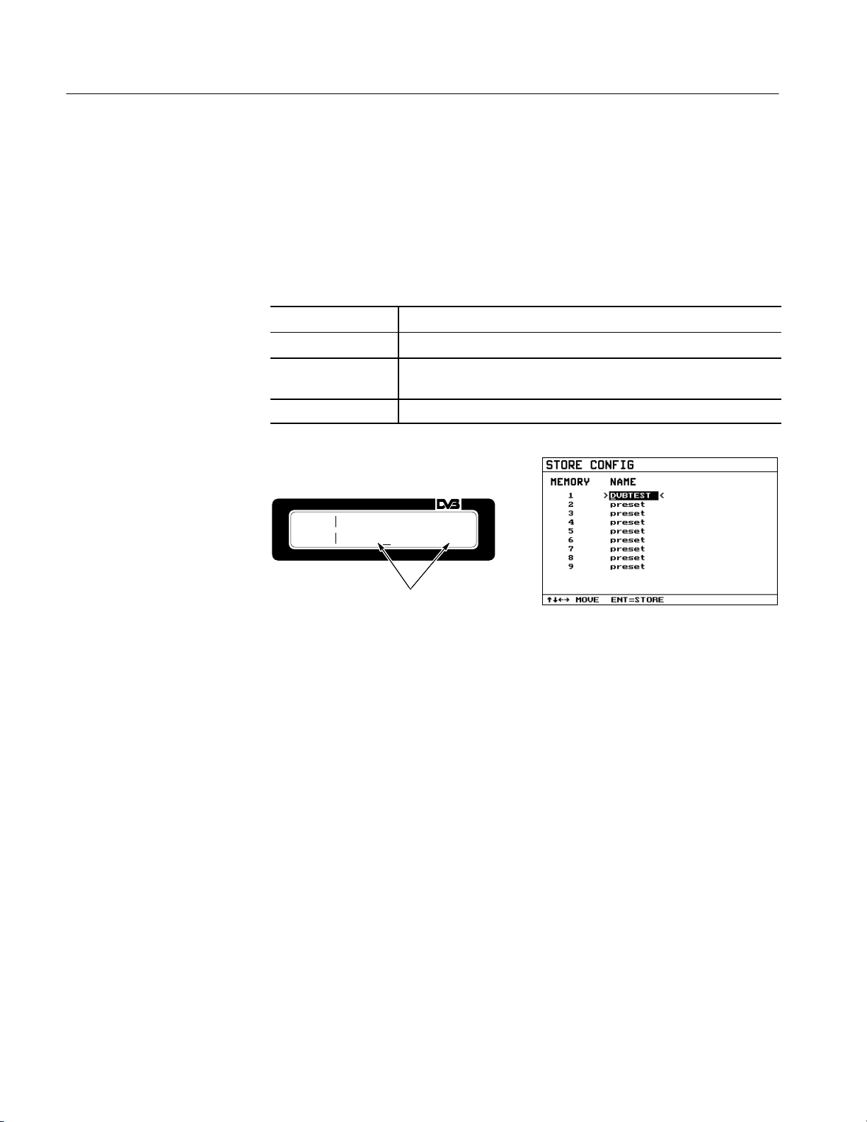
Manual Operation
Entering Text
The name and configuration in the STORE CONFIG and RECALL CONFIG
menus must be entered in the form of text. Set the cursor to the text to be
changed with the aid of keys y b a ' . ENTER activates the entry mode which
is indicated by ‘ > ’ before and by ‘ < ’ after the text to be modified. Set the
cursor to the desired character using keys a ' . The selected character can now
be changed with keys y b . ENTER confirms and terminates the entry. The
entry can be aborted with ESC. In this case, the previous text is retained.
a '
y b
ENTER Starts the entry for the item marked with > ... <, or terminates the entry
ESC Aborts the entered text
Set cursor to the character to be changed
Change the selected character
and takes over the new text
SCTOONFM1EM>NDAVMBE
TEST <
Identifies the entry mode
Figure 4–9: Entering text
4–8
MTD200 MPEG Test Decoder User Manual
Page 71

Overview of Menus
Manual Operation
This section describes the MPEG test decoder operating menus. Abbreviations or
MPEG2-specific expressions are explained in the Glossary. A description of
measurement parameters, measurements, and respective settings are given in
Measurement Functions on page 2–3.
STATUS Menu
The STATUS menu provides information on the transport stream and the
currently decoded program. It indicates the data rate and the ID of the transport
stream, the number, name, and number of lines on program as well as information on encryption. On the OSD, the STATUS menu is displayed in the lower
half of the screen.
y b a '
ENTER Call up MAIN menu
ESC Switches the STA TUS menu display in the OSD on and of f (see
Data rate of applied
transport stream
Call up MAIN menu
SETUP/ON SCREEN DISPLAY Menu on page 4–32).
Program coded
with 625 lines
TS:1328.W1D2R33Mbs 625CL
A
Program
number
Program
name
Program
encrypted
Figure 4–10: STATUS menu
If no transport stream is present at the selected input or if the MPEG test decoder
is in the TS_SYNC LOSS state, an indication is made in the TS data rate field
with “––––––––” and using front–panel LEDs. If the name of the selected
program is not in the transport stream, “––––––––” is displayed in the field of
the program name.
MTD200 MPEG Test Decoder User Manual
4–9
Page 72
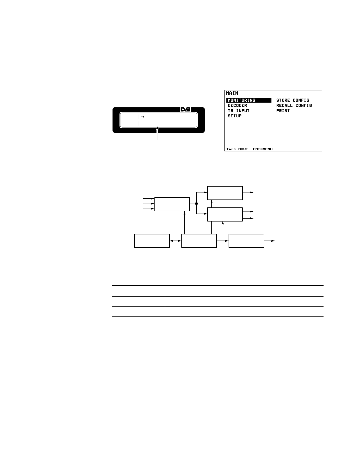
Manual Operation
MAIN Menu
The MAIN menu (see Figure 4–11) contains all top-level operating functions.
The relationship between functions is shown in Figure 4–12.
Submenus
(for example, DECODER)
Figure 4–11: MAIN menu
Measurement results
Video
Audio
Parallel
Serial front
Serial rear
Monitoring
TS Input
Decoder
Store/Recall
Setup
Figure 4–12: Overview of MAIN menu
y b a '
ENTER Calls up the selected submenu
ESC Returns to the STA TUS menu
Set cursor to desired submenu
Print
RS-232
4–10
MTD200 MPEG Test Decoder User Manual
Page 73
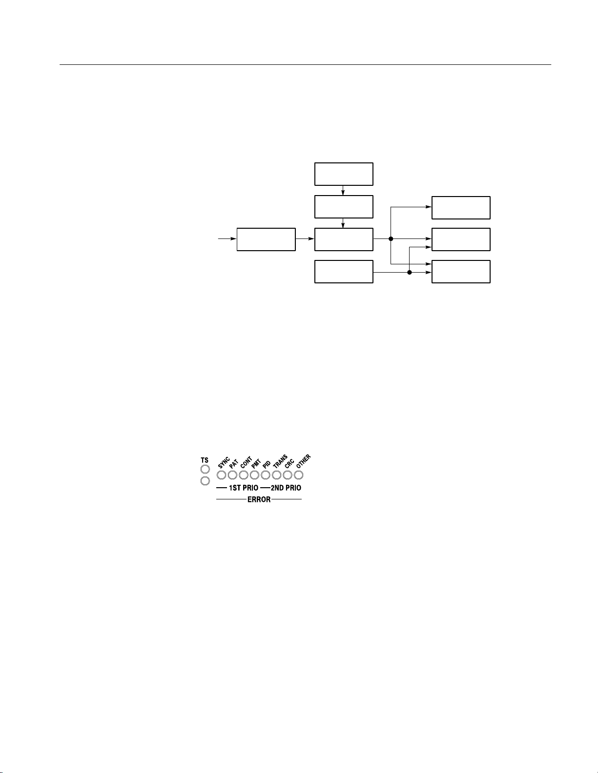
Manual Operation
MONITORING Menu
The MONITORING menu provides the functions required for configuration of
measurements on the MPEG2 transport stream and for presentation of the
measurement results. See Figure 4–13.
Default limits
Front panel
LEDs
Statistics
Reports
TS
Select
program
Limits
Parameter
group
Start Stop Clear
Figure 4–13: Functions of MONITORING menu
For monitoring the syntax of the transport stream, measurements are performed
in line with the ‘Measurement guidelines for DVB systems (ETR 290). Refer to
Measurement Functions.
All first-priority parameters and two second-priority parameters (Transport_error
and CRC_error) are assigned an LED on the front panel. See Figure 4–14. All
other second-priority and third-priority parameters are indicated by the OTHER
LED. See Table 2–1 on page 2–3.
Figure 4–14: Front-panel LEDs indicating parameters
The parameters are cyclically checked. Any error detected is signaled by the
respective LED on the front panel or indicated in the MONITORING/STATISTICS Menu or MONITORING/REPORT Menu. Individual parameters can
be selected and deselected for monitoring in the MONITORING/PARAMETER
GROUP menu. Limits for the PCR values and PSI and SI tables can be specified
in the MONITORING/LIMITS menu. The limits with the standardized values
for DVB and MPEG can be predefined in the MONITORING/DEFAULT menu.
MTD200 MPEG Test Decoder User Manual
4–11
Page 74

Manual Operation
MONITORING/STATISTICS Menu. Errors in the MPEG2 transport stream are
indicated in the MONITORING/STATISTICS menu as specified by (ETR 290)
(refer to Measurement Functions).
Set cursor to parameter (for example, SECOND PRIORITY ERROR :
y b a '
PTS)
a '
ENTER Displays the content of MONITORING/REPORT for this parameter
ESC Returns to MONITORING menu
Call up the MONITORING/CONTROL menu
MSOTNAIT2[.2P1R]I*OPRTISTY
Error counter
error status
ParameterCurrent
Figure 4–15: MONITORING/STATISTICS Menu
In the menu, a distinction is made between first-, second- and third-priority
errors. The pertaining parameters are listed under the respective priority. Each
parameter is preceded by an error counter.
Errors are indicated in error seconds; the counter is incremented by 1 for each
second in which an error of the respective parameter occurs at least once. At a
maximum of 99 error seconds, the counter stops until the monitoring is cleared
(refer to MONITORING/CONTROL Menu on page 4–14).
4–12
If the monitoring of a parameter is switched off (see MONITORING/REPORT
Menu on page 4–13), the respective error counter in the LCD indicates [––]. In
the OSD, the deactivated parameter is marked in a darker color (for example,
gray instead of white).
If an error occurs for a monitored parameter, the pertaining front-panel LED
comes on for 1 second and an asterisk (*) is displayed in front of the parameter
name. In the OSD the error counter is displayed in red. If error conditions are no
longer met after one second has expired, the counter is displayed in yellow and
the asterisk in front of the parameter name is cleared.
In the ‘ELAPSED TIME’ field of the OSD, the monitoring time is displayed in
days, hours, minutes, and seconds.
MTD200 MPEG Test Decoder User Manual
Page 75

Manual Operation
After selecting a parameter by means of the cursor key, the content of
MONITORING/STATISTICS menu for the respective parameter only is
displayed when the ENTER key is pressed.
MONITORING/REPORT Menu. The MPEG test decoder is able to record errors that
occurred in the transport stream. A nonvolatile memory that accepts 1000 entries
is provided for this purpose. If all 1000 memory locations are occupied, the next
entry clears the first one, and the other 999 entries are shifted by one position.
Entry No. 1 becomes No. 0, No. 2 becomes No. 1, etc. The new entry is written
into the now empty position 999. The data in this report memory is retained even
after instrument power-off.
Time Date
R0E0P41C9R:C2:7P:A0T0 15-OCT
0
Current number
in report
Error type:
CRC error
Description of
error source:
PAT with PID 0
Figure 4–16: MONITORING/REPORT Menu
y b a '
b '
a b
a '
ENTER Displays a detailed description of error conditions for this report entry in
ESC Returns to MONITORING menu
Set cursor to desired entry in the report
Set cursor to last entry in the report
Set cursor to first entry in the report
Call up the MONITORING/CONTROL menu
the OSD
The report in the OSD is divided into four columns. The column ‘NO’ lists the
current numbers of report entries. Under ‘TIME’ the time when the error or
operating event occurred is recorded. Under ‘EVENT’ the type of the event, (for
example, CRC error of PAT), is indicated. If the event refers to a specific PID,
this is indicated in the column ‘PID’.
In the ‘ELAPSED TIME’ field of the MONITORING/STATISTICS Menu, the
monitoring time is displayed in days, hours, minutes and seconds.
MTD200 MPEG Test Decoder User Manual
4–13
Page 76

Manual Operation
MONITORING/CONTROL Menu. In the MONITORING/CONTROL menu,
monitoring of the transport stream can be controlled. This control influences the
display in the MONITORING/STATISTICS Menu and in the MONITORING/
REPORT Menu.
MCOONNITTROORLING *SCTLOEP
AR
Display with monitoring stopped
MCOONNITTROORLING *SSTTAORPT
Display with ongoing monitoring
Figure 4–17: MONITORING/CONTROL menu
y b a '
ENTER Executes the selected action (for example, starts monitoring)
ESC Returns to the MONITORING menu
Set cursor to desired action (for example, ST AR T)
Actions available for monitoring:
START Starts monitoring of transport stream. The error seconds are
determined and the detected errors recorded in the report. The
START action is entered in the report.
STOP Stops monitoring of transport stream. Error seconds are no
longer determined nor the report updated. The STOP action is
entered in the report and only available during an ongoing
measurement. An interrupted measurement can be continued
with START.
CLEAR Resets the display of error seconds in the MONITORING/STA-
TISTICS Menu to 0, and clears the content of the report.
Clearing does not affect the status of an ongoing measurement;
the measurement is not stopped nor is an interrupted measurement restarted. The error seconds counters are reset. The content
of the report is cleared and the time in the ‘ELAPSED TIME’
field is reset to 0:00:00.
4–14
MTD200 MPEG Test Decoder User Manual
Page 77

Manual Operation
MONITORING/PARAMETER GROUP Menu. For monitoring the transport stream, the
measurement parameters (see Table 2–1 on page 2–3) can be activated individually in an M-out-of-N selection. Only error seconds for active parameters are
signaled to LEDs, indicated in the MONITORING/STATISTICS Menu and
entered in the report (refer to MONITORING/REPORT Menu on page 4–13).
ParameterActivated for
monitoring
Figure 4–18: MONITORING/PARAMETER GROUP menu
y b a '
ENTER Switches monitoring for the selected parameter on ‘[X]’ or off ‘[ ]’
ESC Returns to the MONITORING menu
Set cursor to desired parameter (for example, FIRST PRIORITY
ERROR: TS SYNC)
The structure of this menu is identical to that of the MONITORING/STATISTICS Menu. Instead of the error counter, the marker for parameter monitoring on ‘[X]’ or off ‘[ ]’ is displayed in front of each parameter.
MONITORING/LIMITS Menu. In addition to active state of individual parameters,
the limits for the distances of PCR values and PSI and SI tables can be indicated
(see Table 4–1). When a limit is exceeded, the error condition is considered
fulfilled and an error is entered in the report and error seconds in the statistics for
active parameters.
MTD200 MPEG Test Decoder User Manual
4–15
Page 78

Manual Operation
Parameter name
Á
Á
Á
Á
Á
Á
Á
Á
Á
Á
Á
Á
Á
Á
T able 4–1: Limit values for parameters
Adjustable limits According to DVB According to MPEG
MIN MAX MIN MAX MIN MAX
PAT Distance 0 ms – 100 ms 0.1 s – 60.0 s 25 ms 0.5 s 25 ms 0.5 s
CA T Distance
PMT Distance
БББББ
NIT Distance
БББББ
SDT Distance
BA T Distance
EIT Distance
RST Distance
TDT Distance
TOT Distance
PCR Distance
PCR Discontinuity
PTS Distance
PID Distance
PID unref. Duration
0 ms – 100 ms
0 ms – 100 ms
ÁÁÁ
0 ms – 100 ms
ÁÁÁ
0 ms – 100 ms
0 ms – 100 ms
0 ms – 100 ms
0 ms – 100 ms
0 ms – 100 ms
0 ms – 100 ms
0 ms – 10 ms
–––
–––
–––
–––
0.1 s – 60.0 s
0.1 s – 60.0 s
ÁÁÁÁ
0.1 s – 60.0 s
ÁÁÁÁ
0.1 s – 60.0 s
0.1 s – 60.0 s
0.1 s – 60.0 s
–––
0.1 s – 60.0 s
0.1 s – 60.0 s
0.01 s – 1.00 s
0.01 s – 1.00 s
0.1 s – 60.0 s
0.1 s – 60.0 s
0.1 s – 60.0 s
25 ms
25 ms
ÁÁÁ
25 ms
ÁÁÁ
25 ms
25 ms
25 ms
25 ms
25 ms
25 ms
0 ms
–––
–––
–––
–––
0.5 s
0.5 s
ÁÁÁ
10 s
ÁÁÁ
2 s
10 s
2 s
–––
30 s
30 s
0.04 s
0.1 s
0.7 s
0.5 s
0.5 s
25 ms
25 ms
ÁÁÁÁ
–––
ÁÁÁÁ
–––
–––
–––
–––
–––
–––
0 ms
–––
–––
–––
–––
0.5 s
0.5 s
–––
–––
–––
–––
–––
–––
–––
0.1 s
–––
–––
–––
–––
ÁÁÁ
ÁÁÁ
Parameter
MLOINMIITPAMTINDIST2A5NCmE
s
Upper limit
of repetition rate
UnitTime value
Figure 4–19: MONITORING/LIMITS menu
y b
a '
ENTER Starts entry of numerals and enters value (refer to Entering Numerals
ESC Returns to MONITORING menu
Set cursor to desired parameter (for example, P AT DISTANCE)
Switch between MIN and MAX value of parameter
on page 4–7)
4–16
MTD200 MPEG Test Decoder User Manual
Page 79

Manual Operation
MONITORING/DEFAULT LIMITS Menu. In this menu the limits with the values
stipulated for DVB or MPEG can be predefined.
The two following standards are provided:
H MPEG ISO/IEC 13818-1, dated 13 November 1994
H DVB ETR 290, dated 28 June 1996
Only the limit values stipulated in the corresponding standard are predefined.
The values marked with ‘–––’ in Table 4–1 on page 4–16 are not influenced by
this setting.
MDOLNIIMMDPVEBGIESTOR/I2E9C
0
Figure 4–20: MONITORING/DEFAULT LIMITS menu
y b a '
ENTER
ESC Returns to the MONITORING menu
Set cursor to desired standard
Predefines limit values with the standard values (see Table Table 4–1
on page 4–16
)
MTD200 MPEG Test Decoder User Manual
4–17
Page 80

Manual Operation
MONITORING/SELECT PROGRAM Menu. In this menu, you can be define whether
the programs to be monitored are to be selected manually or automatically by the
decoder.
Monitored programs are
selected automatically
MSOPNRI
G*AMUATNOUASLELSEECLTEC
Monitored programs are
selected manually
Figure 4–21: MONITORING/SELECT PROGRAM Menu
y b a '
ENTER Cursor is set to:
ESC Returns to the MONITORING menu
Set cursor to the desired function
AUTO SELECT ALL PROGRAMS:
The programs to be monitored are selected automatically.
MANUAL SELECTION:
The programs to be monitored can be selected in MONITORING/
SELECTED PROGRAMS
EDIT / VIEW SELECTED PROGRAMS
Calls up the MONITORING/SELECTED PROGRAMS menu
AUTO SELECT ALL PROGRAMS:
After creating a new transport stream, all the programs are selected for moni-
toring, if possible. If more than 10 PMTs or more than 64 programs are in the
stream, only the first 10 PMTs and a maximum of 64 programs referenced in the
tables are monitored.
MANUAL SELECTION:
After applying a new transport stream, it is first checked to see if at least one of
the programs selected in the MONITORING/SELECTED PROGRAMS menu
for monitoring is contained in the transport stream. If not, the AUTO SELECT
ALL PROGRAMS mode is enabled and the programs are selected automatically.
4–18
MTD200 MPEG Test Decoder User Manual
Page 81

Manual Operation
MONITORING/SELECTED PROGRAMS Menu. In the MANUAL SELECTION
mode, the programs to be monitored can be selected in this menu. Up to 64
programs, referenced in a maximum of 10 PMTs, can be monitored.
Number of PMT’s
used by monitored
programs
PID of PMT by
which this program
is referenced
Program is
monitored
Figure 4–22: MONITORING/SELECTED PROGRAMS Menu
y b a '
a '
ENTER In MANUAL SELECTION mode: switching monitoring for the desired
ESC Returns to the MONITORING/SELECT PROGRAM Menu
Set cursor to the desired program
In MANUAL SELECTION mode: switching monitoring of all programs
off.
program on [X] or off [ ]
On the OSD, a list with all the programs available in the transport stream is
output. Field ‘SEL.PROGRAMS’ indicates how many programs are currently
monitored. Display ‘USED PMTS’ indicates in how many different PMTs the
programs are referenced.
There are some restrictions when monitoring single programs:
PMT ERROR only determined for the PMTs used by the monitored
PID ERROR only determined for the PIDs used by the monitored
CRC ERROR only determined for the PMTs used by the monitored
PCR ERROR only determined for the PCR values of the monitored
PCR ACCURACY only determined for the PCR values of the monitored
MTD200 MPEG Test Decoder User Manual
programs
programs
programs for the PMTs
programs
programs
4–19
Page 82

Manual Operation
PTS ERROR only determined for the PCR values of the monitored
programs
SI REPEAT ERROR only determined for the PMTs used by the monitored
programs for the PMTs
UNREF PID no longer determined
DECODER Menu
With the decoder section of the MPEG test decoder, a program can be decoded
independently and in parallel to the monitoring functions selected in the
MONITORING menu. See Figure 4–23.
Video output
Video output
TS
Select
program
Select
program
element
Monitor type
Figure 4–23: Interaction of DECODER functions
The program to be decoded is selected from the programs of the applied data
stream in the DECODER/SELECT PROGRAM menu.
If the selected program consists of more than one video, audio and data stream, a
detailed selection of program elements can be made in the DECODER/SELECT
PROGRAM ELEMENT menu.
The video standard for the analog video output is set in the DECODER/VIDEO
OUTPUT menu. The audio output can be muted in the DECODER/AUDIO
OUTPUT menu.
4–20
The aspect ratio of the connected monitor can be selected in the DECODER/
MONITOR TYPE menu.
MTD200 MPEG Test Decoder User Manual
Page 83
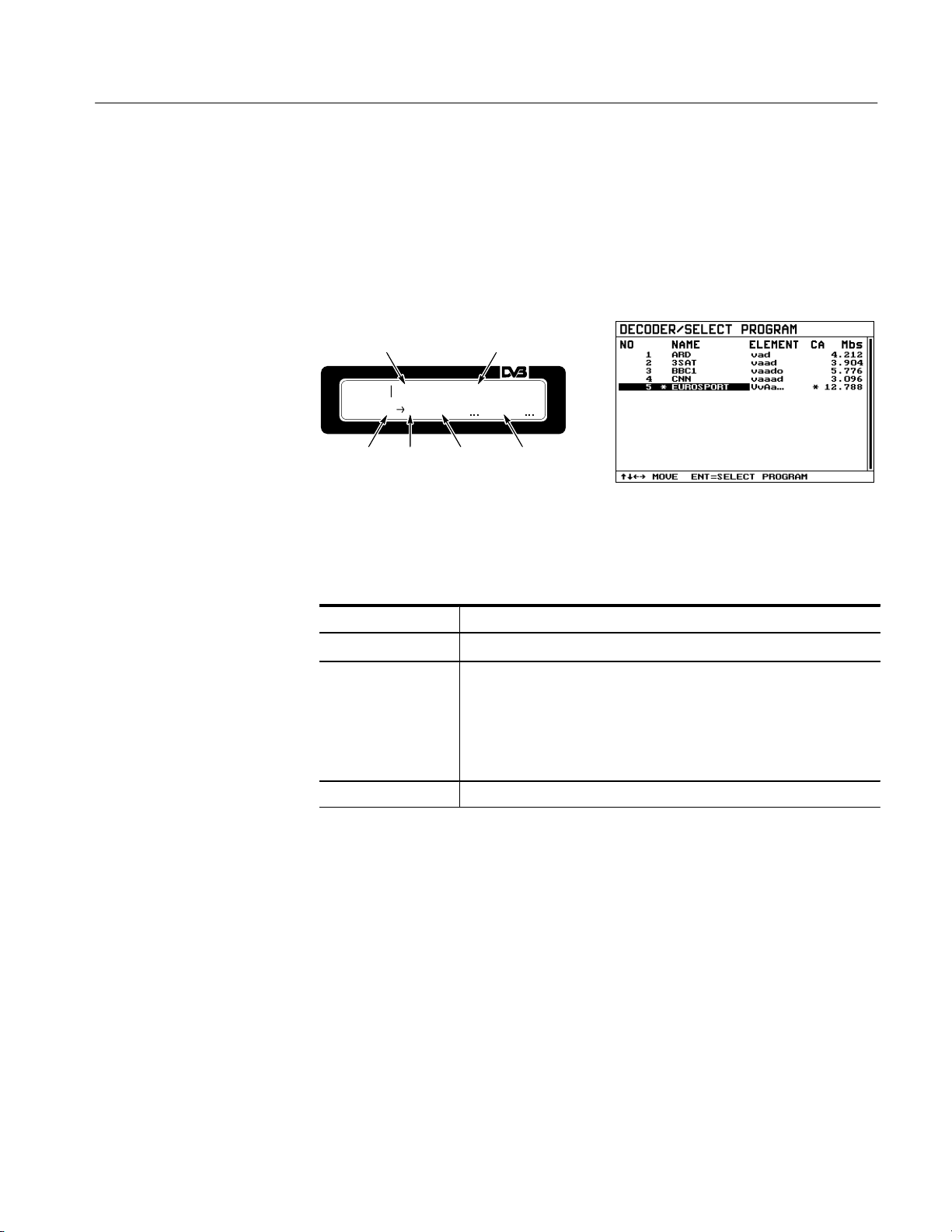
Manual Operation
DECODER/SELECT PROGRAM Menu. In the DECODER/SELECT PROGRAM
menu, a decoding program can be selected. For the selection, the PAT, PMT, and
SDT tables in the MPEG2 data stream are evaluated and the programs in the
transport stream displayed on the LDC and the OSD (see Figure 4–24). Also, the
total data rate of the SI tables as well as the data rate of the null packets are
displayed.
Conditional access Data rate of program
PROG5C*A
.78V8vMAbas
EURO1S2P
Program
number
Decoded
program
Program
name
Program
elements
Figure 4–24: DECODER/SELECT PROGRAM menu: Selecting a program via its
name
a '
y b
ENTER With the cursor in the column
ESC Returns to the DECODER menu
Set cursor to column containing program name or program elements
Set cursor to the desired entry in the respective column
Program name: Decodes the selected program and marks it with
an asterisk (*).
Program element: Calls up the DECODER/SELECT PROGRAM
ELEMENT menu.
The menu in the OSD has five columns. The first three can be selected with
cursor keys a ' . The two last columns contain only program-specific informa-
tion and cannot be selected.
MTD200 MPEG Test Decoder User Manual
4–21
Page 84

Manual Operation
NO Program number
NAME Program name
ELEMENT Program elements indicated in the following form:
V = video A = audio D = data O = others
The currently decoded elements are represented by capital letters,
for example, ‘VaAad’ means that the program consists of a video, three
audio, and one data stream.
The video stream and the second audio stream are decoded.
CA Conditional access
An asterisk (*) indicates that at least one program element is encrypted
Mbs Data rate of program in MBits/s,
specified for monitored programs only (see MONITORING/SELECT
PROGRAM Menu on page 4–18)
The program to be decoded is selected via the name in the program list.
Program selection via name:
1. Set the cursor to the name of the desired program
2. Activate decoding of this program with ENTER.
Take care that the program list is displayed after the MPEG2 data stream has
been applied.
If the transport stream does not contain a description of the program names
(for example, there is no SDT-table or service descriptor), “––––––––” is
output for the name.
4–22
MTD200 MPEG Test Decoder User Manual
Page 85

Manual Operation
DECODER/SELECT PROGRAM ELEMENT Menu. For selecting program elements,
set the cursor to the element display of the desired program in the DECODER/
SELECT PROGRAM menu and press ENTER. The program elements are
displayed with PID, type, code, conditional access, and data rate in the subsequently opened DECODER/SELECT PROGRAM ELEMENT menu.
Conditional access Data rate of program
P*REOUG
ROSCPA5060.000*0VIMDbEsO
Program
name
PID of
program
element
Selected
element
Program
element
Figure 4–25: DECODER/SELECT PROGRAM ELEMENT menu
a '
y
b
ENTER Selects the desired program element to be decoded.
ESC Returns to the DECODER/SELECT PROGRAM menu
Set cursor to the desired program element
Sets cursor to the first program element
Sets cursor to last program element
The selected element is marked with an asterisk (*).
A selection is only possible if more than one element of a type are
available
The program with number, name and brief information on elements, conditional
access, and total data rate is displayed in the first line of the OSD. Below this
line, the respective program elements are listed.
MTD200 MPEG Test Decoder User Manual
4–23
Page 86

Manual Operation
The five columns of the list provide the following information:
PID PID of program element
TYPE Type of program element (for example, VIDEO).
The first element is the PMT providing detailed program information;
the second element is the PID of the PCR values
CODE Type of program element as number as stipulated in standard IEC/ISO
13818
CA Conditional access,
an asterisk (*) indicates that the program is encrypted
Mbs Data rate of program element in MBit/s,
specified for elements of monitored programs only (refer to MONITOR-
ING/SELECT PROGRAM Menu on page 4–18)
A video and an audio stream can be selected from this list. If the selected
program is being decoded, element settings immediately affect the decoding
procedure. If the program is not decoded at present, settings of the program
elements become effective when the program is selected in the DECODER/SELECT PROGRAM menu.
Settings of program elements are assigned to the transport stream currently
applied to the MPEG test decoder and remain in the memory until either the
content of the transport stream changes, another transport stream is applied or
another input is selected.
DECODER/SI TABLES Menu. The data rates of the SI tables are displayed in
detail in this menu.
yba'
ESC Returns to DECODER/SELECT PROGRAM menu
Sets cursor in the list
The complete data rate of the SI tables is displayed in the first line of OSD. The
individual tables are listed below. The three columns have the following
meaning:
PID PID of SI table
TABLE Name of SI table
Kbs Indication of data rate of an SI table in KBit/s,
for PMT s only indicated for those tables whose programs are monitored
(see section 4.3.3.7)
4–24
MTD200 MPEG Test Decoder User Manual
Page 87
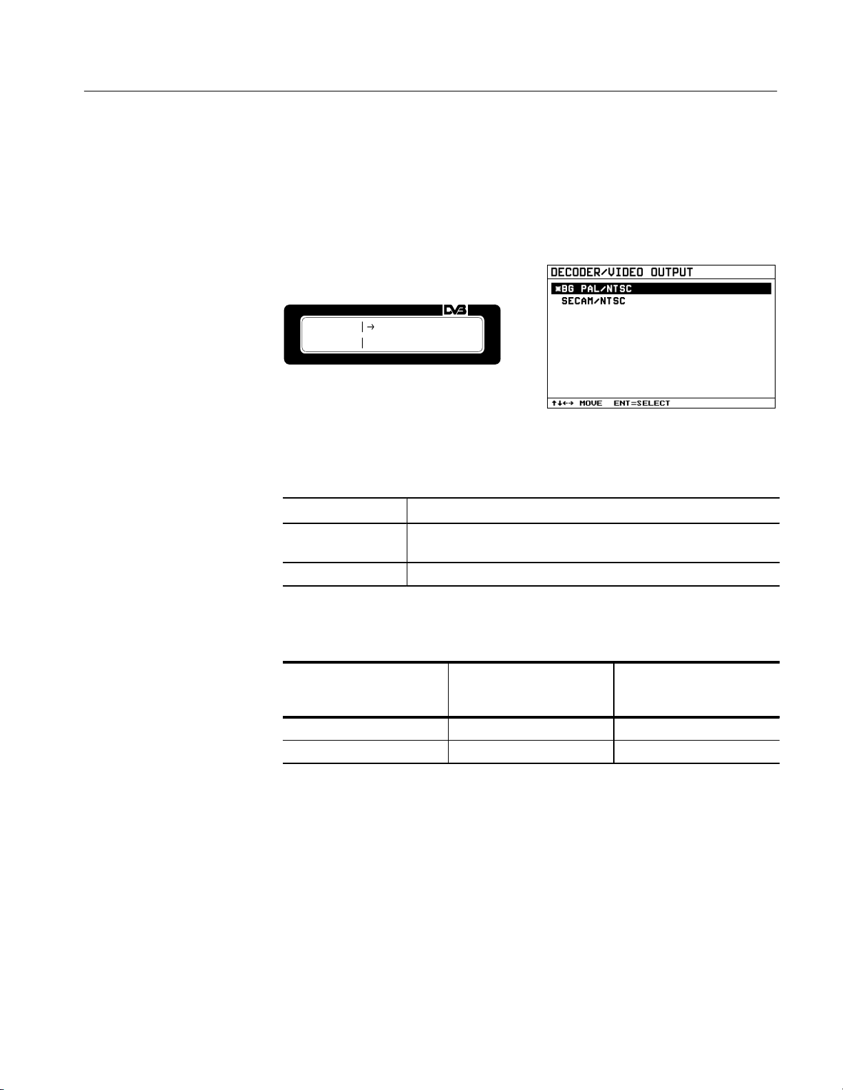
Manual Operation
DECODER/VIDEO OUTPUT
Menu. For a program coded with 525 lines, the MPEG
test decoder provides the video standard M/NTSC at the analog video outputs
CCVS and Y/C. If the program is coded with 625 lines, a selection can be made
between standards B/G PAL and SECAM. Switchover between 625 and 525
lines depends on the decoded program and is automatic.
VOIUDTEPOUT*BSGECPAAML//NNTTSSCC
Figure 4–26: DECODER/VIDEO OUTPUT menu
y b a '
ENTER Selects the desired video standard.
Set cursor to desired video standard for 625 lines
The selected standard is marked with an asterisk (*).
ESC Returns to DECODER menu
T able 4–2: Selectable video standards
Setting in
DECODER/VIDEO OUTPUT
menu
PAL/NTSC B/G PAL M/NTSC
SECAM/NTSC SECAM M/NTSC
Video standard for
program with 625 lines
Video standard for
program with 525 lines
MTD200 MPEG Test Decoder User Manual
4–25
Page 88
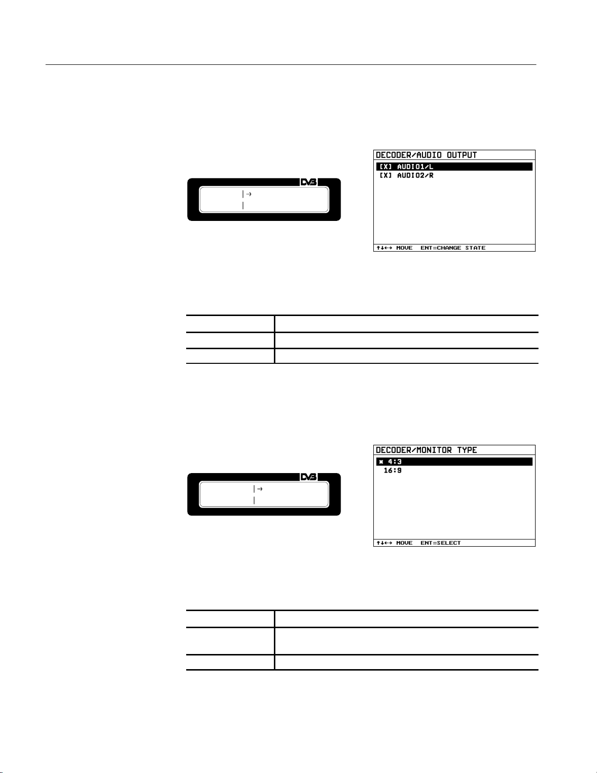
Manual Operation
DECODER/AUDIO OUTPUT Menu. In this menu, the two audio channels can be
switched on and off.
AOUUDTIPOUT[[XX]]AAUUDDIIOO12//L
R
Figure 4–27: DECODER/AUDIO OUTPUT menu
y b a '
ENTER Switches AUDIO1/L or AUDIO2/R on-[X] or off [ ]
ESC Returns to DECODER menu
Set cursor to desired item
DECODER/MONITOR TYPE Menu. In this menu, the aspect ratio of the connected
monitor can be selected. The output format of the program to be decoded is
adapted to the set aspect ratio.
DMEOCNO.DTEYRPE*146::3
9
Figure 4–28: DECODER/MONITOR TYPE menu
4–26
y b a '
ENTER Selection of desired aspect ratio,
ESC Returns to the DECODER menu
Set cursor to desired aspect ratio
the selected aspect ratio is marked with an asterisk (*)
MTD200 MPEG Test Decoder User Manual
Page 89

Manual Operation
TS INPUT ROUTE Menu
The TS INPUT menu provides the functions required for selecting the input for
the MPEG2 transport stream and for configuring synchronization to the transport
stream.
Parallel
Serial front
Serial rear
Root
TSSync condition
Figure 4–29: Interaction of functions in the TS INPUT menu
TS INPUT/ROUTE Menu. In the TS INPUT/ROUTE menu, the input for the
transport stream can be selected.
IRNOPUUTT
E*PSAERR.IALFFRROONNTT
Figure 4–30: TS INPUT/ROUTE menu
y b a '
ENTER Selects the desired input, and marks it with an asterisk (*).
ESC Returns to the TS INPUT menu
Set cursor to desired transport stream input
The following three inputs are provided on the MPEG test decoder for the
MPEG2 data stream:
H PARALLEL parallel input (LVDS) at front panel
H SERIAL FRONT serial, asynchronous input (BNC) on front panel
H SERIAL REAR serial, asynchronous input (BNC) at the rear.
CAUTION. The maximum data rate may be 54 Mbit/s. A packet may have a length
of 188 Byte or 204 Byte (188 data bytes + 16 error-correction bytes).
MTD200 MPEG Test Decoder User Manual
4–27
Page 90

Manual Operation
TS INPUT/SYNC CONDITION Menu. The sync lock and sync loss is monitored from
the TS INPUT/SYNC CONDITION menu.
SCYONNCDLLOOCSKS52PPAACCKKEET
T
Figure 4–31: TS INPUT/SYNC CONDITION menu
yba'
ENTER Calls up the entry of numerals (refer to Entering Numerals on
ESC Returns to TS INPUT menu
Set cursor to LOCK or LOSS
page 4–7) and enters the number of sync bytes.
For monitoring synchronization to the MPEG2 transport stream, a sync
hysteresis can be generated separately for sync lock and sync loss. The sync
hysteresis specifies the number of successive valid/invalid sync words received
before the measurement decoder identifies a sync lock (TS SYNC LOCK) or
sync loss (TS SYNC LOSS).
LOCK Number of valid sync words before TS SYNC LOCK is
recognized, selectable between 1 and 31
LOSS Number of invalid sync words before a TS SYNC LOSS is
recognized, selectable between 1 and 7
4–28
MTD200 MPEG Test Decoder User Manual
Page 91

Manual Operation
PRINT Menu. The PRINT menu provides all functions required for the output
of test reports, program contents and device settings to a printer. The output is in
the form of ASCII text via the RS–232 interface (see Set up RS232 Menu on
page 4–33). Only common control characters are used. The page length is fixed
to 60 lines. At the end of each line a <carriage return> (0Dhex) and a <line feed
> (0Ahex) is sent, and at the end of the page <form feed> (0Chex). With this
configuration any printer equipped with a serial interface can be used.
Figure 4–32: PRINT menu
yba'
ENTER The submenu for starting or stopping the desired printout is called up.
ESC Returns to MAIN menu
Set cursor to required item
The following information can be printed:
STATISTICS Hardcopy of currently displayed MONITORING/STATISTICS menu
REPORT Content of MONIT ORING/REPORT Menu. The range to be printed is
selectable. The range added to the report since the last printout is
preset.
PROGRAM INFO List of detailed contents of applied data stream.
CONFIG Current settings of MPEG2 Measurement Decoder DVMD.
MTD200 MPEG Test Decoder User Manual
4–29
Page 92

Manual Operation
PRINT/STATISTICS, REPORT, PROGRAM INFO, CONFIG Menu. The
submenus for starting the printing for the four different contents are identical.
The PRINT/REPORT menu is given as an example. This menu allows the
selection of the range to be printed.
yba'
ENTER Cursor is set to:
ESC Returns to PRINT menu
Set cursor to required function
SELECT LINES:
Calls up the menu for selecting the report entries to be
printed. This entry is only available in PRINT/REPORT
menu.
ST ART PRINTING:
Starts printing
CANCEL PRINTING:
Cancels the current printing process
PRINT/REPORT/SELECT LINE Menu. This menu allows the selection of
the range of the report to be printed. The selected range on OSD is displayed in
white. The entries that are not selected are displayed in a darker color. On the LC
display, the selected entries are marked with an asterisk (*).
When these menus are displayed, the report entries added since the last report
printout are preselected.
yba'
b'
ay
ENTER Switch on/off marker mode
Marker mode on:
The range to be printed can be marked by means of the
cursor.
Marker mode off:
Moving through the report is possible with the cursor.
Set cursor to last entry in report
Set cursor to first entry of report
4–30
When switching on the marker mode an existing marking is deleted.
ESC Returns to PRINT/REPORT menu
MTD200 MPEG Test Decoder User Manual
Page 93

Manual Operation
STORE CONFIG and
RECALL CONFIG Menu
The MPEG test decoder has nine memory locations for storing complete
instrument setups. When setups are stored, a name is assigned to each of the nine
configurations. One of the nine stored setups (or a 10th setup) can be called up
again. Memory location 10 (PRESET) holds the factory-set configuration and
cannot be changed.
SCTOONFME1MNDAVMBE
TEST
SCTOONFME1M>NDAVMBE
TEST <
Figure 4–33: STORE CONFIG and RECALL CONFIG menu
y b a '
ENTER RECALL CONFIG:
Set cursor to desired memory location
Loads the selected instrument setup.
STORE CONFIG:
Stores current settings in the selected memory. First the text editor is
called up for entering a name. When the entry is confirmed with
ENTER the settings are stored.
ESC Returns to the MAIN menu
CAUTION. The following settings and data are not stored with the STORE
CONFIG function and are reloaded unvaried when a stored setup is called up:
H Content of error counter in the MONITORING/STATISTICS menu
H Content of report in the MONITORING/REPORT menu
H Content of program list in the DECODER/SELECT PROGRAM menu
H Settings of program elements in the DECODER/SELECT PROGRAM
ELEMENT menu, except those for the currently decoded program
MTD200 MPEG Test Decoder User Manual
4–31
Page 94

Manual Operation
SETUP Menu
The SETUP menu provides all general functions for configuring the OSD, the
serial interface, and the internal clock.
SETUP/ON SCREEN DISPLAY Menu. In the menu, the OSD can be switched on and
off.
Figure 4–34: SETUP/ON SCREEN DISPLAY menu
y b a '
ENTER Switches the OSD on or off
Set cursor to ‘ON’ or ‘OFF’
ESC Returns to SETUP menu
DISPLAY OFF Menus are displayed on LCD only.
DISPLAY ON Menus are displayed on LCD and OSD simultaneously.
In the STATUS menu, the OSD can be switched off with
ESC. The OSD is switched on again by pressing any
key.
4–32
MTD200 MPEG Test Decoder User Manual
Page 95

Manual Operation
SETUP/RS-232 Menu. In this menu, the operating parameters of the serial interface
can be configured.
SREST2U3P2BPAAURD
ITY9N6O0N0E
Figure 4–35: SETUP/RS-232 menu
y b
ENTER Calls up the entry mode:
ESC Returns to SETUP menu
Set cursor to the item to be changed (for example, P ARITY)
Select setting (for example, parity NONE, with cursor keys
The new setting is stored with ENTER or cleared with ESC.
BAUD Selectable baud rates for data transmission:
1200, 2400, 4800, 9600, 19200
PARITY Selectable parity for data transmission:
NONE No parity
EVEN Even parity
ODD Uneven parity
PACE Selectable handshake for data transmission:
NONE No handshake used.
XON/XOFF Handshake with XON and XOFF.
RTS/CTS Handshake with RTS and CTS.
Data transmission uses 8 data bits and one stop bit.
y b).
NOTE. Hardware handshake must be used for transmitting block data via the
RS-232 interface, since control characters (XON / XOFF) are not recognized.
The latter may be part of the block data stream.
MTD200 MPEG Test Decoder User Manual
4–33
Page 96

Manual Operation
SETUP/DATE+TIME Menu
. In this menu, the date and time for the clock is set.
DTAITMEE0118-:O2C8T:-318996
Figure 4–36: SETUP/DA TE+TIME menu
y b
ENTER Calls up the entry mode:
ESC Returns to SETUP menu
Set cursor to date or time
The new date or time are entered in the same way as numerals. Set
the cursor to the digit or month to be varied using keys a ' . The
selected digit is varied with cursor keys
stored with ENTER. The entry is aborted with ESC.
y b and the entered value is
4–34
MTD200 MPEG Test Decoder User Manual
Page 97

Page 98

Remote Control
The MTD200 MPEG Test Decoder is fitted with an RS-232-C interface as
standard. The connector is located at the rear of the instrument and permits an
external controller to be connected. The instrument supports the Standard
Commands for Programmable Instruments (SCPI), version 1995.0. The SCPI
standard is based on the IEEE 488.2 standard and aims at a standardization of
device-specific commands, error handling, and status registers (refer to SCPI
Introduction on page 5–4).
Basic knowledge of SCPI programming and operation of the controller is
required for a clear understanding of this chapter.
The requirements of the SCPI standard on the command syntax, error handling
and configuration of the status registers are described in detail in the relevant
sections. Tables provide a quick overview of the commands implemented in the
instrument and the assignment of the bits in the status registers. The tables are
supplemented by a detailed description of commands and status registers. For the
description of the commands, a basic knowledge of the MPEG test decoder
manual operation is assumed.
All program examples for control via RS-232 are written in C for the program
package V24.Tools Plus from Langner.
Brief Instructions
The following brief operating instructions allow you to quickly put the instrument into operation and to set the basic functions:
1. Connect the MPEG test decoder to the controller via a null-modem cable.
2. Set the MPEG test decoder (menu item SETUP/RS232) to 9600 baud, 8 bits,
parity NONE, 1 stop bit, and the protocol PACE.
3. Start a terminal program on the controller, and set it to the same protocol as
the MPEG test decoder.
4. Enter the following command sequence:
a. DISP:OSD:MODE ON
b. SYST:DISP:CONT STAT
c. CONF:MON:CONT CLEA
d. CONF:MON:CONT START
MTD200 MPEG Test Decoder User Manual
5–1
Page 99

Remote Control
Starting Remote Control
The MONITORING REPORT is cleared and monitoring restarted. On the
OSD (On Screen Display), the MONITORING/STATISTICS menu is
displayed.
5. To return to manual operation:
a. Press any key on the front panel.
The menu for switchover to LOCAL is opened on the display.
b. Set the cursor to LOCAL and confirm with ENTER.
On power up, the MPEG test decoder is automatically set to in the manual mode
(LOCAL) and can be operated from the front panel. Starting remote control
(REMOTE) is made as soon as a character is received via the RS-232 interface.
The MPEG test decoder remains in the REMOTE state until it is switched back
to the manual mode, either manually or via the RS-232 interface (refer to Return
to Manual Operation on page 5–3). Switching from the manual mode to remote
control and vice versa has no effect on the instrument settings.
Setting the Transmission
Parameters
Indications in Remote
Control
To ensure error-free data transmission, the same transmission parameters must be
set on the MPEG test decoder and the controller. The parameters can be varied
either manually in the SETUP/RS232 menu or via remote control using the
SYSTem:COMMunicate:SERial:... commands.
The following transmission parameters are the factory default settings:
Baud rate = 9600
Bits = 8, stop bits = 1
Parity = NONE
Protocol = NONE
In remote control, REMOTE is indicated in the STATUS menu. The MPEG test
decoder features four different display modes for the OSD which must be
switched on with command DISPlay:OSD:MODE ON. The display modes are
selected my means of command SYSTem:DISPlay:CONTents STATistic | ... and
are as follows:
STATistic MONITORING\STATISTICS menu displayed on the OSD
REPort MONITORING\REPORT menu displayed on the OSD
5–2
MTD200 MPEG Test Decoder User Manual
Page 100

Remote Control
PROGram DECODER/PROGRAM menu displayed on the OSD
INFO STATUS menu displayed on the OSD
Return to Manual
Operation
If the MPEG test decoder is in the remote-control mode, press any key on the
front panel to call up the menu for switchover to LOCAL mode. Set the cursor to
LOCAL, and confirm with ENTER.
NOTE. Prior to the switchover all commands must have been fully processed;
otherwise, remote control is immediately switched on again.
Switchover to LOCAL mode lockout can be disabled by the command
SYSTem:KLOC ON. This command prevents inadvertent switchover.
Cancel LOCAL switchover lockout by using the command SYSTem:KLOC OFF.
Device-Dependent Messages (Commands and Responses)
Device-dependent messages are transmitted on the data lines of the remote-control interface using the ASCII/ISO code. Device-dependent messages are
differentiated according to the direction in which they are sent via the interface:
Commands are messages sent by the controller to the device. They control the
device functions and request information. The commands are differentiated by
two criteria:
1. The effect they have on the device.
Setting commands trigger device settings (for example, resetting of the
instrument).
Queries cause data to be provided for output via the IEC/IEEE bus (for
example, for device identification or query of the active input).
2. Their definition in the IEEE 488.2 standard.
Common commands are precisely defined in their function and notation in
the IEEE 488.2 standard. They concern functions, such as the management
of the standardized status registers, resetting, and self test.
Device-specific commands relate to functions that depend on device
characteristics, such as the frequency setting. Part of these commands are
standardized by the SCPI Consortium (refer to SCPI Introduction
page 5–4).
MTD200 MPEG Test Decoder User Manual
5–3
 Loading...