


Digital and Mixed Signal Oscilloscopes
MSO/DPO70000 Series Datasheet
Four-channel Simultaneous Performance
Up to 23 GHz Bandwidth
Up to 50 GS/s Real-time Sample Rate
Up to 500 Megasample Record Length with MultiView Zoom™ for
quick navigation
Fastest Waveform Capture Rate with >300,000 wfms/s maximum
per channel
16 Logic Channels with 80 ps Timing Resolution for Debug of digital
and analog signals (MSO70000 Series only)
Unique iCapture® capability enables viewing analog characteristics of
digital channels with single probe connection
6.25 Gb/s Real-time Serial Trigger – Assures triggering on the first
instance of a specified NRZ or 8b/10b pattern to allow isolation of
pattern-dependent effects
Application Support for High-speed Serial Industry Standards,
wideband RF, Power supplies, and memory – Enables standardspecific certification, measurement automation, and ease of use
Engineers rely on an oscilloscope throughout their design cycle, from
prototype turn-on to production testing. The MSO/DPO70000 Series
oscilloscopes' unique capabilities combined with exceptional signal
acquisition performance and analysis accelerate your measurement tasks.
Key performance specifications
Up to 33 GHz analog bandwidth and rise time as fast as 9 ps. Enables
measurement on the latest high-speed serial standards
True 33 GHz Real-time Analog Bandwidth on 2 Channels with 33 GHz
models
Industry-leading sample rate and timing resolution
100 GS/s on 2 Channels (33, 25, 23, 20, 16, and 12.5 GHz
models)
Key features
Superior signal integrity and excellent signal-to-noise ratio – observe
the truest representation of your waveform
Pinpoint® triggering – minimize time spent trying to acquire problem
signals for efficient troubleshooting and shortened debug time
Visual Trigger – precisely qualify triggers and find unique events in
complex waveforms
Search and Mark – provides waveform or serial bus pattern matching
and software triggers for signals of interest
Automated Serial Analysis options for PCI Express, 8b/10b encoded
serial data, I2C, SPI, CAN, LIN, FlexRay, RS-232/422/485/UART, USB
2.0, HSIC, MIL-STD-1553B, and MIPI® C-PHY, D-PHY and M-PHY
P7600 and P7500 TriMode™ probing system – perfectly matched
signal connectivity
P6780, P6750, and P6717A high-performance 17-channel logic probes
with bandwidths up to 2.5 GHz for connections to today's fast digital
signals (MSO70000 Series only)
Connectivity
USB 2.0 host port on both the front panel and rear panel for quick and
easy data storage, printing, and connecting a USB keyboard
Integrated 10/100 Ethernet port for network connection and Video Out
port to export the oscilloscope display to a monitor or projector
www.tek.com 1

Datasheet
Quick selection guide
Model Analog Bandwidth Analog Sample Rate –
2/4 Channels
DPO70404C 4 GHz 25 GS/s 31 MS 4 —
MSO70404C 4 GHz 25 GS/s 62 MS 4 16
DPO70604C 6 GHz 25 GS/s 31 MS 4 —
MSO70604C 6 GHz 25 GS/s 62 MS 4 16
DPO70804C 8 GHz 25 GS/s 31 MS 4 —
MSO70804C 8 GHz 25 GS/s 62 MS 4 16
DPO71254C 12.5 GHz 100 GS/s / 50 GS/s 31 MS 4 —
MSO71254C 12.5 GHz 100 GS/s / 50 GS/s 62 MS 4 16
DPO71604C 16 GHz 100 GS/s / 50 GS/s 31 MS 4 —
MSO71604C 16 GHz 100 GS/s / 50 GS/s 62 MS 4 16
DPO72004C 20 GHz 100 GS/s / 50 GS/s 31 MS 4 —
MSO72004C 20 GHz 100 GS/s / 50 GS/s 62 MS 4 16
DPO72304DX 23 GHz 100 GS/s / 50 GS/s 31 MS 4 —
MSO72304DX 23 GHz 100 GS/s / 50 GS/s 62 MS 4 16
DPO72504DX 25 GHz 100 GS/s / 50 GS/s 31 MS 4 —
MSO72504DX 25 GHz 100 GS/s / 50 GS/s 62 MS 4 16
DPO73304DX 33 GHz 100 GS/s / 50 GS/s 31 MS 4 —
MSO73304DX 33 GHz 100 GS/s / 50 GS/s 62 MS 4 16
Standard Memory –
Analog + Digital
Analog Channels Logic Channels
Application support
High-speed serial industry standards compliance
SignalVu® RF and vector signal analysis
DDR memory bus analysis
Applications
Design verification including signal integrity, jitter, and timing analysis
Design characterization for high-speed, sophisticated designs
Certification testing of serial data streams for industry standards
Memory bus analysis and debug
Prototype turn-on and power supply verification
Research and investigation of transient phenomena
Production testing of complex systems
Spectral analysis of transient or wide-bandwidth RF signals
System turn-on and verification
From the time a design is first powered up through the initial operational
checks, the MSO/DPO70000 Series provide the features you need.
Uncompromised four-channel acquisition
With very low noise and up to 50 GS/s sample rate on all four channels the
DPO70000 Series ensures that signal integrity checks and timing analysis
can be done without worrying about noise and jitter in the scope distorting
the measurements. Single-shot bandwidths up to 23 GHz on all four
channels ensure that you'll capture your signals of interest without worrying
about undersampling when using more than 1 or 2 channels.
For applications requiring the lowest internal noise and jitter, 100 GS/s
performance further reduces noise and jitter and provides additional
measurement headroom.
2 www.tek.com

Digital and Mixed Signal Oscilloscopes – MSO/DPO70000 Series
Unmatched acquisition and signal-to-noise
performance
The superior signal integrity and excellent signal-to-noise ratio of the MSO/
DPO70000 Series ensures confidence in your measurement results.
Up to 33 GHz, matched across 4 channels
Bandwidth enhancement eliminates imperfections in frequency
response all the way to the probe tip. User-selectable filters for each
channel provide magnitude and phase correction for more accurate
representation of extremely fast signals. In addition, only Tektronix
allows the user to disable the bandwidth enhancement for applications
needing the highest measurement throughput.
Simultaneous high sample rate on all channels captures more signal
details (transients, imperfections, fast edges)
100 GS/s on 2 channels and 50 GS/s on all analog channels for
the 12.5 through 33 GHz models
25 GS/s on all analog channels for the 4, 6, and 8 GHz models
12.5 GS/s on all logic channels in the MSO70000 Series
Low jitter noise floor and high vertical accuracy provide additional
margin in your measurements
Long record length provides high resolution and extended-duration
waveform capture
Standard 31 MS per channel on the DPO70000 Series and 62 MS
on the MSO70000 Series
Optional up to 125 MS on all four channels (4, 6, and 8 GHz
models) and 250 MS (12.5 through 20 GHz models) on all four
channels; up to 500 MS on four channels/1 GS on two channels for
23, 25, and 33 GHz models.
On the MSO70000 Series, the record length of logic channels
matches the analog record lengths for uncompromised analog and
digital acquisition
MultiView Zoom helps you manage long records, compare and
analyze multiple waveform segments
Widest range of probing solutions
Whether you need to measure 8 Gb/s serial data, fast digital logic, or
switching currents from your new power supply design, Tektronix offers a
vast array of probing solutions, including active single-ended, differential,
logic, high voltage, current, optical, and a wide range of probe and
oscilloscope accessories.
P7633 Low Noise TriMode probes simplify complex measurement setups.
With high signal-to-noise ratio and low internal noise floor, the MSO/
DPO70000 Series enable you to perform precise characterization
measurements. When debugging a DUT, a low noise floor and
maximum signal fidelity of the measurement instrument allows you to
find the smallest anomalies affecting the DUT's performance. For RF
signals, a lower noise floor translates into a higher dynamic range,
opening the MSO/DPO70000 Series to a wider range of applications.
P6780 Differential Logic probes provide high-bandwidth connections for up to 16 digital
signals.
www.tek.com 3

Datasheet
16-channel digital acquisition (MSO70000 Series)
When you have many interfaces to verify, the MSO70000 Series with
4 analog and 16 logic channels enables efficient channel-to-channel timing
checks. With timing resolution of 80 ps, the MSO70000 Series' digital
acquisition system enables you to make precise timing measurements on
as many as 20 channels simultaneously.
iCapture™ – One connection for analog and digital
(MSO70000 Series)
The number of signals that must be verified can often make the checkout of
a design long and involved. By using the iCapture™ digital-to-analog
multiplexer feature, you can easily verify the analog characteristics of any
of the 16 signals connected to the MSO70000 Series' digital channels
without changing probes or connections. Using iCapture™, you can quickly
view the analog characteristics of any input channel. If the signal is working
as expected, relegate it to a digital-only view and continue testing other
lines.
Bus decoding and triggering
Verifying your system operation often requires the ability to see specific
system states on a key bus such as the DDR SDRAM interface. The MSO/
DPO70000 Series includes parallel and serial bus decoding that provides
deeper insight into the system's behavior. Using the bus triggering
capability of the MSO/DPO70000 Series to isolate the exact state needed
or find invalid bus sequences is as easy as defining the bus and choosing
the bit pattern or symbolic word that describes the desired state. In
addition, serial bus decoding for 8b/10b encoded data, I2C, SPI,
RS-232/422/485/UART, USB, and MIPI® DSI and CSI2 buses enables you
to identify where control and data packets begin and end as well as identify
subpacket components such as address, data, CRC, etc.
Deep record length available on all channels
Longer duration events such as power supply sequencing and system
status words can be analyzed without sacrificing timing resolution using the
long memory depths available on all four analog channels in the DPO70000
Series as well as the 16 logic channels of the MSO70000 Series. Optional
memory depths up to 125 MS (Option 10XL) on the 4, 6, and 8 GHz
models, 250 MS (Option 20XL) on the 12.5 through 20 GHz models and
500 MS (4 channels)/1 GS (2 channels) with option 50XL on the 23 through
33 GHz models are available.
10 ms duration capture of synchronous high-speed and low-speed signals at 25 GS/s.
Power supplies can be a critical failure point in any system. Careful testing
of the power delivery system's power on sequence can be time consuming.
The MSO70000 Series provides independent logic thresholds for each logic
channel enabling multiple logic voltages to be set up and observed
simultaneously for quick verification of the system's power rails.
Symbolic bus formats simplify identifying system states and setting up bus triggers.
Protocol and serial pattern triggering
To verify serial architectures, the serial pattern triggering for NRZ serial
data streams with built-in clock recovery in the MSO/DPO70000 Series
allows correlating events across physical and link layers. The instruments
can recover the clock signal, identify transitions, and allow you to set the
desired encoded words for the serial pattern trigger to capture. This feature
comes standard on the MSO70000 Series and is available on the
DPO70000 Series as Option ST6G. For higher bit rate standards like USB
3.0, the 8b/10b serial pattern trigger and decode covers data rates up to
6.25 Gb/s.
Pattern lock triggering adds an extra dimension to NRZ serial pattern
triggering by enabling the oscilloscope to take synchronized acquisitions of
a long serial test pattern with outstanding time base accuracy. Pattern lock
triggering can be used to remove random jitter from long serial data
patterns. Effects of specific bit transitions can be investigated, and
averaging can be used with mask testing. Pattern lock triggering supports
up to 6.25 Gb/s NRZ serial data streams and is standard on the MSO70000
Series instruments, or is included as part of Option ST6G on the
DPO70000 Series.
4 www.tek.com

Digital and Mixed Signal Oscilloscopes – MSO/DPO70000 Series
Visual Trigger – Find the signal of interest quickly
Finding the right cycle of a complex bus can require hours of collecting and
sorting through thousands of acquisitions for an event of interest. Defining a
trigger that isolates the desired event speeds up debug and analysis
efforts.
Visual Trigger qualifies the Tektronix Pinpoint Triggers by scanning through
all waveform acquisitions and comparing them to on-screen areas
(geometric shapes). Up to eight areas can be created using a mouse or
touchscreen, and a variety of shapes (triangles, rectangles, hexagons, or
trapezoids) can be used to specify the desired trigger behavior. Once
shapes are created, they can be edited interactively to create ideal trigger
conditions
Visual Trigger extends the Tektronix oscilloscope's triggering capabilities
for a wide variety of complex signals as illustrated by the examples shown
here.
By triggering only on the most important signal events, Visual Trigger can
save hours of capturing and manually searching through acquisitions. In
seconds or minutes, you can find the critical events and complete your
debug and analysis efforts. Using the Mark All Trigger Events feature, once
your Visual Trigger is set, your oscilloscope can automatically search the
entire acquired waveform for all events with the same characteristics and
mark them for you - a great time-saving feature.
DDR memory bus events involve clocks, strobes and data channels as well
as multiple amplitudes and bursts of data.
Customized serial triggering. Visual Trigger set to find a serial data pattern of 1101 0101.
Multiple channel triggering. Visual Trigger areas can be associated with events spanning
multiple channels such as packets transmitted on two USB2.0 buses simultaneously.
DDR memory. Visual Trigger used to isolate a rare occurrence of a write burst on a
specific bit pattern in DDR3. The trigger event is a Write DQ burst of 11000000, when the
DQ launch starts from a non-tri-state voltage value. DDR memory bus events involve
clocks, strobes and data channels as well as multiple amplitudes and bursts of data.
Boolean logic trigger qualification. Boolean logic using logical OR allows the user to
simultaneously monitor each bit and capture the occurrence of an anomaly at any point
in the acquisition.
www.tek.com 5

Datasheet
Trigger on the width of a burst of 10 pulses. By drawing a "Must be outside" area before
the first clock pulse and a second "Must be outside" area after the tenth pulse, as shown,
you can define a Visual Trigger setup that captures the desired burst width.
With deep acquisition memory, margin testing can be done over many
cycles and long duration trends in the data can be observed. Plus, data
from the oscilloscope can be captured into Microsoft Excel using the unique
Excel toolbar, and formatted into custom reports using the Word toolbar
provided with the MSO/DPO70000 Series.
Automated tools to increase measurement throughput
Ease of use and measurement throughput are key when a large number of
measurements must be completed with a performance oscilloscope.
MSO70000 Series come standard with the DPOJET Advanced Jitter and
Eye Diagram measurement application, providing the tools you need to
quickly perform a high volume of measurements and collect statistics.
DPOJET Essentials is standard on the DPO70000 Series with the DPOJET
advanced version available as an option. Application-specific measurement
packages are also available that extend DPOJET and perform the
extensive set of tests required by industry standard groups. User-defined
measurements can be added to DPOJET using the Application Developers
Kit (ADK) that comes standard with the oscilloscope.
System characterization and margin testing
When a design is working correctly and the next task is to fully characterize
its performance, the MSO/DPO70000 Series offers the industry's most
comprehensive set of analysis and certification tools, such as math
expressions, waveform mask testing, pass/fail testing, event searching, and
event marking. Tools for automation reduce the tedium, increase reliability,
and speed up the process of making hundreds of characterization
measurements.
Advanced waveform analysis
Full analysis of the power, voltage, and temperature corners of your system
under test can be very time consuming. The MSO/DPO70000 Series offer a
wide range of built-in advanced waveform analysis tools.
Waveform cursors make it easy to measure trace-to-trace timing
characteristics, while cursors that link between YT and XY display modes
make it easy to investigate phase relationships and Safe Operating Area
violations. Select from 53 automatic measurements using a graphical
palette that logically organizes measurements into Amplitude, Time,
Histogram, and Communications categories. Gather further insight into your
measurement results with statistical data such as mean, min, max,
standard deviation, and population.
Define and apply math expressions to waveform data for on-screen results
in terms that you can use. Access common waveform math functions with
the touch of a button. Or, for advanced applications, create algebraic
expressions consisting of live waveforms, reference waveforms, math
functions, measurement values, scalars, and user-adjustable variables with
an easy-to-use calculator-style editor.
DPOJET Jitter and Eye Diagram Analysis – Simplify identifying signal integrity concerns,
jitter, and their related sources with DPOJET software. DPOJET provides the highest
sensitivity and accuracy available for real-time oscilloscopes.
To support the DPO7OE1 optical probe, DPOJET now also provides optical
measurements, such as Extinction Ratio (ER), Average Optical Power
(AOP), Optical Modulation Amplitude (OMA), Optical High value, and
Optical Low value.
6 www.tek.com

Digital and Mixed Signal Oscilloscopes – MSO/DPO70000 Series
Error detector
When performing receiver testing on a serial transceiver, a BER
measurement is often required. The MSO/DPO70000 series offer an
optional built-in error detector function for 8b/10b-encoded signals. The
built-in error detector comes with presets for testing PCIe, USB3.0, and
SATA signals up to 6 Gb/s. The error detector settings can be customized
to work with a generic 8b/10b-encoded signal and can be set to detect bit,
character, or frame errors. When an error is detected, the scope will trigger
and display the waveform bits where the error occurred.
RF and vector signal analysis
When vector signal analysis of RF or baseband signals is needed, the
optional SignalVu® application enables measurements in multiple domains
(frequency, time, phase, modulation) simultaneously. SignalVu
®
measurements are fully correlated with the scope's time domain acquisition
and triggering. Time domain events, such as commands to an RF
subsystem, can be used as trigger events, while the subsystem's RF signal
can be seen in the frequency domain. SignalVu also provides wireless
standards measurements such as IEEE 802.11 a/b/g/j/p/n/ac that can be
correlated in the time domain 1.
TekExpress® software automation framework
The TekExpress® software automation framework has been developed for
automated one-button testing of high-speed serial data standards.
TekExpress® efficiently executes the required tests for many serial
standards such as SATA, SAS, MIPI® C-PHY, MIPI® D-PHY, MHL, MIPI
M-PHY, PCI Express®, USB 3.0, DisplayPort, and 10GBASE-T Ethernet.
Run on an external Windows PC, the TekExpress® software orchestrates
the instrument setup and control sequences to provide complete test
results for complete design validation.
Beyond using the TekExpress® framework, custom applications that you
develop yourself using application development environments such as
MATLAB® can further extend the tool set of the MSO/DPO70000 Series.
Characterization measurements depend upon accuracy and repeatability.
The wide bandwidth and unmatched signal fidelity of the MSO/DPO70000
analog front end ensures that your signal quality measurements such as
rise times are faithful and amplitude correct with flatness of ±0.5 dB.
®
SignalVu® Vector Signal Analysis – Easily verify wide-bandwidth designs such as
wideband radar, high data-rate satellite links, WLAN 802.11, or frequency-hopping radios
and characterize wideband spectral events. SignalVu® combines the functionality of a
vector signal analyzer, a spectrum analyzer, and the powerful triggering capabilities of
the MSO/DPO70000 Series – all in a single package.
1
Also check http://www.tek.com/signalvu for the latest information.
TekExpress® USB 3.0 Automated Test Software (Option USB-TX) – TekExpress
USB 3.0 provides an automated, simple, and efficient way to test USB 3.0 transmitter
and receiver hosts and devices consistent with the requirements of the SuperSpeed
Universal Serial Bus Electrical Compliance Test Specification. The application automates
selection of appropriate fixture de-embed, CTLE and reference channel emulation filters
and measurement selections based on device type, test type, test points, and selected
probes. In addition, USB-TX leverages DPOJET allowing debug and advanced
characterization of USB 3.0 solutions.
®
www.tek.com 7

Datasheet
TekExpress® SATA Automated Compliance Test Software – Complete support for
SATA Gen1/2/3 defined test suites for transmitters and receivers. Reduce your
compliance test time by approximately 70% with simple, efficient automation of all
required test suites with TekExpress® software. Also included is auto-recognition of all
required test equipment, precise DUT/Host control, and one-button testing.
TekExpress® MHL Advanced Analysis and Compliance Software (Option MHD) Provides the most comprehensive solution for MHL 1.0/2.0/1.3/2.1 compliance testing as
well as debug and validation of MHL devices against the latest MHL specifications. The
application automates Transmitter, Sink and Dongle Electrical tests. Results are
presented in a comprehensive HTML format for engineering test documentation
TekExpress® PCI Express Gen 1/2/3 Automated Test Software (Option PCE3) Provides the most comprehensive solution for PCI Express Gen 1/2/3 transmitter
compliance testing as well as debug and validation of PCI Express devices against the
PCI-SIG specifications. The application automates selection of appropriate fixture deembed and reference channel emulation filters and measurement selections based on
test type, device data rate, transmitter equalization, link width, and selected probes. In
addition, the Option PCE3 application includes a TekExpress compliance automation
solution that integrates the PCI-SIG's Sigtest test software with Tektronix' DPOJETbased PCI Express Jitter and Eye Diagram & SDLA Serial Data Link Analysis Visualizer
analysis tools for debug. Results are presented in a comprehensive HTML format for
engineering test documentation.
Custom filter and de-embed capability
Create your own filters or use the filters provided as standard with the
MSO/DPO70000 Series to enhance your ability to isolate or remove a
component of your signal (noise or specific harmonics of the signal). These
customizable FIR filters can be used to implement signal-processing
techniques, such as removing signal pre-emphasis or minimizing the
effects of fixtures and cables connected to the device under test. Using the
optional Serial Data Link Analysis Visualizer (SDLA64) application, you can
gain further insight into serial data links with the capability to emulate the
serial data channel from its S-parameters, remove reflections, crosscoupling, and loss caused by fixtures, cables, or probes, and open closed
eyes caused by channel effects using receiver equalization techniques,
such as CTLE, DFE, FFE. IBIS-AMI models for silicon-specific receiver
equalization can used to observe on-chip behavior.
8 www.tek.com

Digital and Mixed Signal Oscilloscopes – MSO/DPO70000 Series
SDLA - Serial Data Link Analysis Visualizer (Option SDLA64) – Offers the capability
to emulate the serial data channel, de-embed fixtures, cables, or probes, and add or
remove equalization. Option SDLA64 also provides processing of waveforms with IBISAMI Receiver Equalization, or CTLE, FFE and/or DFE equalization. DPOJET provides
advanced measurement and jitter analysis of the resulting waveforms.
Application-specific solutions – enable
standard-specific certification, measurement
automation, and extended signal analysis
Accurate, Simple, and Customizable Physical Layer Certification Testing –
For designers with industry-standard certification needs, standard-specific
compliance and analysis modules that configure the pass/fail waveform
mask and measurement limit testing are available as options on the MSO/
DPO70000 Series. Modules are available for PCI Express®, DDR Memory,
Serial ATA, SAS, HDMI, Ethernet, DisplayPort, MIPI® C-PHY, MIPI® DPHY and M-PHY, Power Supplies, and USB.
See the following list for highlights of the available application-specific
solutions:
DDR Memory Bus Analysis (Option DDRA) – Automatically identify DDR1, LPDDR,
LPDDR2, LPDDR3, DDR2, DDR3, DDR4, and GDDR3 Reads and Writes and makes
JEDEC conformance measurements with pass/fail results on all edges in every Read
and Write burst. DDRA provides capabilities for measurements of clock, address, and
control signals. In addition to enabling conformance testing DDRA with DPOJET is the
fastest way to debug complex memory signaling issues. DDRA can also use the
Command/Address lines to trigger on specific read/write states when running on the
MSO70000 Series Mixed Signal Oscilloscope, which offers 16 channels of digital logic
probing.
USB 3.0 Transmitter Test Solution (Option USB3) – Perform verification,
characterization, and debug of USB 3.0 devices. Measurements are implemented in
DPOJET and are compliant to the USB 3.0 specification. For compliance and
automation, USB-TX is available.
www.tek.com 9

Datasheet
PCI Express® Transmitter Compliance and Debug (Option PCE3) – Analyze the
performance of your PCI Express® Rev 1.0, 2.0, or 3.0 (draft spec) design with
comprehensive test support. Using DPOJET, Option PCE3 enables tests that conform to
PCI-SIG standards.
NRZ and PAM4 measurements-The throughput of Datacom networks continues to
increase. Tek's DPO72504DX and DPO73304DX support up to 10GBASE KRn data
rates. The powerful combination of the DPO70000, DPOJET Jitter and Noise Analysis,
and the SDLA Serial Data Link Analysis tool performs accurate de-embedding and eye
diagram analysis for Datacom standards.
For more information on PAM4 testing, please refer to the DPO70000SX
datasheet and related PAM4 documents.
Ethernet Compliance Test Solution (Option ET3)
Ethernet variants 10BASE-T, 100BASE-TX, and 1000BASE-T with the comprehensive,
integrated Tektronix® Ethernet tool set. Analog verification, automated compliance
software, and device characterization solutions are all included.
C-PHY uses a unique mechanism for clock recovery. C-PHY 1.0 implements a custom
clock recovery algorithm referred to as triggered eye. In this model, the first zero crossing
of the four differential signals is used as a trigger point for clock recovery and rendering
the eye diagram. The eye mask is optimally placed for maximum eye opening where the
eye height is measured. Because of the triggered eye mechanism, all the jitter at the
trigger point (zero crossing) is swallowed and reflected on the other side. Jitter and eye
diagram rendering performed over the entire record length helps designers better
characterize devices by displaying anomalies of the device over an extended period. The
software allows you to run the eye diagram analysis for 3M UI and overnight runs for a
detailed characterization.
– Receive full PHY layer support for
10 www.tek.com

Digital and Mixed Signal Oscilloscopes – MSO/DPO70000 Series
MIPI® D-PHY Characterization and Analysis Solution (Option D-PHY) – Verify to the
D-PHY specification by rapidly characterizing and discovering sources of jitter and signal
integrity concerns using the fully flexible and customizable test setup. Using DPOJET,
Option D-PHY enables transmitter high-speed data-clock timing measurements, along
with a full range of electrical characteristics in high-speed or low-power modes.
MIPI® M-PHY Debug, Analysis, Characterization and Conformance Test Solution
(Option M-PHY) – Verify to the M-PHY specification by rapidly characterizing and
discovering sources of jitter and signal integrity concerns. Using DPOJET, Option M-PHY
enables transmitter signaling and timing measurements such as differential transmit eye
diagrams, rise and fall times, slew rate, amplitude parameters, common mode voltages
on each lane for both the large and small amplitude configurations, as well as the
terminated and unterminated cases.
XGbT 10GBASE-T Automated Compliance Software – Quickly perform 10GBASE-T
measurements per the IEEE 802.3an-2006 standard including Power Spectral Density
(PSD), Power Level, and Linearity, with a simplified instrument configuration. XGbT
provides flexible control over test configurations and analysis parameters, enabling more
in-depth device characterization.
10GBASE-KR/KR4 Compliance and Debug Solution (Option 10G-KR) - Automated
compliance measurements for IEEE 802.3ap-2007 specifications. This option includes an
automated compliance solution and debugging with DPOJET. The automated test setup
measures transmitter equalization levels generating 12 results for each tap and
120 results for 9 different measurements in approximately 15 minutes.
www.tek.com 11

Datasheet
Tektronix SFP+ QSFP+ Tx is developed on a Real Time Oscilloscope platform, which is
the platform of choice for engineers designing their products around SFF-8431 &
SFF-8634 technology. Option SFP-TX and SFP-WDP enable both an Automation
Solution (for Compliance) and DPOJET Option (for Debug), Users can save up to 80%
on testing time compared to manual testing. TWDPc - Transmitter Waveform Distortion
Penalty for Copper Measurements are available with Option SFP-WDP. SFF-8431 SFP+
TWDPc based Matlab code is integrated into the SFP-WDP option to make sure
Engineers can use this measurement in the automated setup.
DisplayPort Compliance Test Solution (Option DP12) – Supports DisplayPort
Compliance Test Standard (CTS) source test with four-line simultaneous testing using
the Tektronix® P7300SMA Series probes and DisplayPort software. Detailed test reports
with waveform plots, pass/fail results, and margin analysis are included.
HDMI Compliance Test Solution (Option HT3) – A fast, efficient solution for HDMI
compliance measurement challenges, no matter if you are working on a Source, Cable,
or Sink solution. This application provides all the HDMI compliance test solutions you
need to ensure quality and interoperability.
12 www.tek.com
Power Measurement and Analysis Software (Option PWR) – DPOPWR, Advanced
Power Measurement and Analysis software allows the user to configure multiple
measurements with custom defined settings, measure and analyze power dissipation in
switching devices, and magnetic parameters in a single acquisition. The Trajectory plot
computes turn-on loss, turn-off loss and Conduction loss parameters for each cycle.
Measurements such as Phase, Conduction loss, amplitude, and Voltage harmonics
provide more insight to Input/Output characterization of power supplies. A single mht
format file with append feature provides an easy way of generating reports which include
measurements, test results, and plot images.

Certification
This is the start of your concept. Before a product can go to market, you
often need to complete a series of certification tests on the industrystandard high-speed serial buses in your design. These tests can involve
many hours of wrestling with test fixtures, reading certification documents,
and collecting sufficient data to validate that your system passes the
required tests.
MSO70000 – A dedicated solution configured for
today's high-speed serial design challenges
The MSO70000 Mixed Signal Oscilloscopes are specially configured to
address high-speed serial data designs by encapsulating many of the serial
domain features needed for high-speed serial verification and
characterization. These standard features on the MSO70000 Series are
options on the DPO70000 Series.
Digital and Mixed Signal Oscilloscopes – MSO/DPO70000 Series
Serial pattern triggering – Real-time serial pattern triggering and protocol
decode with built-in clock recovery recovers the clock signal, identifies the
transitions, and decodes characters and other protocol data. You can see
the 8b/10b bit sequences decoded into their words for convenient analysis,
and set the desired encoded words for the serial pattern trigger to capture.
With pattern lock triggering, the MSO70000 Series can synchronize to long
serial test patterns with data rates up to 6.25 Gb/s and remove random
jitter.
DPOJET jitter, timing, and eye diagram analysis – The MSO70000
Series features the highest-accuracy jitter and timing measurements as
well as comprehensive analysis algorithms. Tight timing margins demand
stable, low-jitter designs. You can make jitter measurements over
contiguous clock cycles on every valid pulse in a single-shot acquisition.
Multiple measurements and trend plots quickly show system timing under
variable conditions, including Random, Deterministic, and Bounded
Uncorrelated Jitter separation.
Communications mask testing – Provides a complete portfolio of masks
for verifying compliance to serial communications standards. Over
150 masks including the following standards are supported – PCI
Express®, ITU-T/ANSI T1.102, Ethernet IEEE 802.3, ANSI X3.263, Sonet/
SDH, Fibre Channel, InfiniBand, USB, Serial ATA, Serial Attached SCSI,
IEEE 1394b, RapidIO, OIF Standards, Open Base Station Architecture
Initiative (OBSAI), Common Public Radio Interface (CPRI).
Communications mask testing.
62 MS record length – 62 MS on all four channels provides a longer time
sequence at high resolution. Optional record lengths up to 125 MS for the
4, 6, and 8 GHz models, 250 MS for the 12.5 through 20 GHz models and
500 MS (4 channels)/1 GS (2 channels) on 23 to 33GHz models extend the
acquisition time sequence.
With standard features that extend the functionality of the Tektronix
DPO70000 Series to address high-speed serial signal analysis and
certification, the MSO70000 Series offers a specialized instrument that
efficiently addresses your design challenges.
Protocol Decode for High Speed Serial buses
The MSO/DPO70000 Series oscilloscopes provide optional protocol
analysis for HSS buses such as PCI Express gen 1/2/3, MIPI D-PHY (CSI,
DSI) and 8b/10b-encoded buses. With these capabilities, bit sequences
can be decoded into familiar commands and data packets for faster
analysis. With the PCI Express decoder, the data is displayed in a protocolaware view using characters and terms from the standard, such as the
ordered sets: SKP, Electrical Idle, and EIEOS
Table View of the Bus Protocol. The results table provides a protocol view of the bus and
with a mouse click allows correlation of what is happening in the physical layer to what is
happening in the protocol layers.
www.tek.com 13

Datasheet
Protocol and Electrical Views of an HSS Bus. The data in the results table and the
acquired waveform are time correlated, enhancing the ability to identify possible causes
of protocol errors due to electrical signaling.
Both the 8b/10b serial bus trigger and the advanced search and mark
feature on the oscilloscope are integrated with the HSS protocol decode to
quickly isolate events of interest in a HSS data stream.
User-selectable bandwidth limit filters
While wide bandwidth is needed to characterize your high-speed serial
designs, certification testing can require a specific instrument bandwidth
appropriate for the signal's data rate in order to correlate test results
between different test labs. The MSO/DPO70000 Series feature userselectable bandwidth limiting filters. Using these bandwidth limit filters
which range from 500 MHz to 32 GHz, you will ensure that your
measurement is done using the bandwidth specified by the industry
standard.
Debugging
Throughout the design cycle, MSO/DPO70000 Series oscilloscopes
provide the ability to debug malfunctioning subsystems and isolate the
cause. With the high waveform capture rate of FastAcq® you can quickly
identify signal anomalies that occur intermittently – saving minutes, hours,
or even days by quickly revealing the nature of faults so sophisticated
trigger modes can be applied to isolate them. Using Pinpoint® triggers,
infrequent events such as glitches or signal runts caused by bus contention
or signal integrity issues can be captured, analyzed, and then eliminated.
FastAcq® – Expedites debugging by clearly showing
imperfections
More than just color grading or event scanning, the FastAcq® proprietary
DPX® acquisition technology captures signals at more than
300,000 waveforms per second on all four channels simultaneously,
dramatically increasing the probability of discovering infrequent fault
events. And with a simple turn of the intensity knob you can clearly “see a
world others don't see”, displaying the complete picture of your circuit's
operation. Some oscilloscope vendors claim high waveform capture rates
for short bursts of time, but only MSO/DPO70000 Series oscilloscopes,
enabled by DPX® technology, can deliver these fast waveform capture
rates on a sustained basis.
Pinpoint® trigger
Whether you're trying to find a problem signal or need to isolate a section of
a complex signal for further analysis, like a DDR Read or Write burst,
Tektronix Pinpoint® triggering provides the solution. Pinpoint® triggering
allows selection of virtually all trigger types on both A and B trigger events
delivering the full suite of advanced trigger types for finding sequential
trigger events. Pinpoint® triggers provide trigger reset capabilities that
begin the trigger sequence again after a specified time, state, or transition
so that even events in the most complex signals can be captured. Other
oscilloscopes typically offer less than 20 trigger combinations; Pinpoint
®
triggering offers over 1400 combinations, all at full performance. Visual
Trigger extends the Pinpoint Triggering's capabilities, adding another level
of trigger qualification to find important events in a wide variety of complex
signals.
With Enhanced Triggering, trigger jitter is reduced to <100 fs. With this
stability at the trigger point, the trigger point can be used as a measurement
reference.
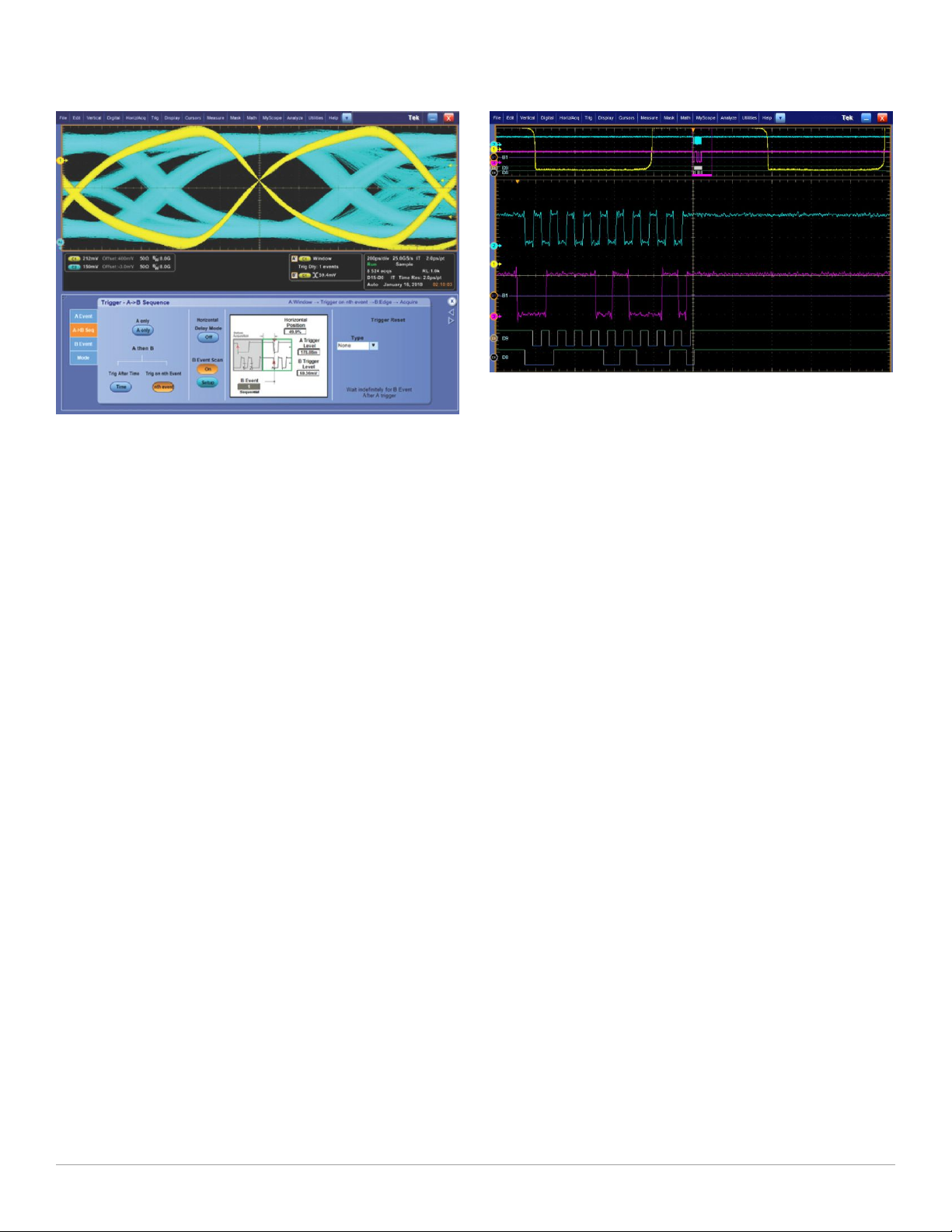
B scan event trigger
Users who wish to create eye diagrams from data bursts synchronized or
initiated by an A event will find the B Event Scan trigger function especially
useful. B Event Scan is an A to B trigger sequence that will trigger and
capture burst event data of interest defined by the B Event setup menu.
Captured bits can be scanned in a sequential or randomized fashion,
alternatively the trigger can toggle between two successive B trigger
events.
14 www.tek.com
B Event Scan identifies specific events to build an eye diagram.
Digital and Mixed Signal Oscilloscopes – MSO/DPO70000 Series
Integrated Logic Channels – Provide time-correlated analog and digital visibility for
system debugging.
Use B Event Scan trigger on DDR DQS edges used to construct an eye diagram of all
bits in a burst.
Logic pattern triggering
Logic pattern triggering allows logic qualification that controls when to look
for faults and ignore events that do not occur during the desired state. On
the MSO70000 Series, up to 20-bit wide logic pattern triggering enhances
the Pinpoint® trigger capabilities by helping you isolate the specific system
state and analog events that are causing system failure.
Digital A then analog B triggering (MSO70000 Series
only)
Advanced triggering capabilities include Digital A then Analog B to help you
to identify a specific digital pattern or system state and then wait for an
analog event such as a runt pulse to trigger the acquisition.
Integrated logic channels (MSO70000 Series only)
The MSO70000 Series extends the debug capabilities of a 4-channel
oscilloscope with an additional 16 logic channels that can be used to
provide system level context when the fault occurs. This context, such as
an illegal system state or error, may be the clue that leads to the root
cause. When other oscilloscopes require you to use a logic analyzer to see
the digital data you need to solve your debugging challenge, the
MSO70000 Series can effectively debug and verify many digital timing
issues in the system more quickly and easily. With 80 ps timing resolution
and channel-to-channel skews of as little as 160 ps, the integrated logic
channels allow you to view and measure time-correlated digital and analog
data in the same display window.
FastFrame
™
When the key events you are interested in are widely spaced in time, such
as bursts of activity on a bus, the FastFrame™ segmented memory feature
on the MSO/DPO70000 Series enables you to capture the events of
interest while conserving acquisition memory. Using multiple trigger events,
FastFrame™ captures and stores short bursts of signals and saves them as
frames for later viewing and analysis. On the MSO70000 Series,
FastFrame™ and bus or logic triggering enable you to capture your fastest,
bursty signals on the analog channels at the highest sample rate while the
logic channel trigger recognizes the bus cycle of interest. Capturing
thousands of frames is possible, so long-term trends and changes in the
bursting signal can be analyzed. Signals captured with FastFrame™ can
also be post-processed using waveform averaging or envelope mode.
iCapture™ (MSO70000 Series only)
When an anomaly is seen on digital lines, iCapture™ delivers new insight
into the analog behavior of the digital signals. With iCapture™, you can
route any 4 of the 16 logic channels to the MSO70000 Series' analog
acquisition system so that these signals can be viewed in finer detail. The
unique multiplexer circuitry of iCapture™ provides simultaneous digital and
analog views of signals without needing to move the logic probe or double
probe the circuit.
Advanced search and mark
Isolating the key event causing your system failure can often be a tedious
task. With the Advanced Event Search and Mark feature standard on the
MSO/DPO70000 Series, examining data and highlighting important events,
skipping the unimportant ones, and enhancing the comprehension of event
relationships is made easy. With ASM, you'll be able to navigate through
long record length acquisitions effortlessly and quickly locate the event you
have been trying to find. Advanced searches can be defined individually or
using the scope's trigger settings as the definition for the search. Even
Visual Trigger areas can be used as part of the ASM criteria.
www.tek.com 15

Datasheet
Advanced Search and Mark – Highlights important events and provides convenient
previous and next buttons and mouse clicks to navigate between events of interest
effortlessly.
Embedded serial bus (I2C, SPI, RS-232/422/485, UART,
USB) decoding and triggering
The low-cost solder tips available for the P7500 TriMode™ probes allow quick connection
so moving the probe to various solder points is fast and easy.
On the MSO70000 Series, the P6780 differential, P6750 high-density DMax®, and P6717A general-purpose logic probes provide connectivity to
low-speed and high-speed digital signals with low loading, small size, and a
range of accessories for soldering or browsing.
The MSO/DPO70000 Series instruments provide integrated support for a
broad range of serial buses – I2C, SPI, RS-232/422/485/UART, and USB.
This support for up to 16 separate serial buses enables you to monitor or
debug subsystems and components, such as frequency synthesizers, D/A
converters, and Flash Memory that are controlled or monitored through
serial control buses. While monitoring or debugging these serial buses
alone is relatively easy, decoding events on the serial bus can also enable
more complex system-level debugging. When you experience an issue with
a higher-speed serial interface, the clue to what is going wrong may be
found by using the serial bus decode feature to observe the data on your
I2C, SPI, RS-232/422/485/UART, or USB interface.
Probing – analog and digital
Often the biggest challenge in debugging a system is getting access to the
required signals. Tektronix offers a wide array of probing solutions,
including the P7600 and P7500 TriMode™ probing system with bandwidths
that are perfectly matched to the MSO/DPO70000 Series. The P7600 and
P7500 TriMode™ probes allow you to switch among differential, single
ended, and common-mode measurements without moving the probe from
its connection points. The P7600 series combines low noise, 33 GHz
bandwidth and the convenience of Trimode probing. The P7500 Series
offers probes with performance from 4 GHz to 25 GHz and offers several
low-cost solder tips with quick connection features that allow moving the
probe to various solder points fast and easy.
Solder tip accessories designed for the P6780 differential logic probes provide access to
signals on tightly spaced vias and fine-pitched components.
DPO7OE1 33 GHz Optical Probe
The DPO7OE1 Optical probe can be used as an Optical Reference
Receiver for high speed serial data signals (using selectable BesselThomson ORR filters), or can be used as a conventional O/E converter for
general wide-bandwidth optical signal acquisition. The DPO7OE1 is
compatible with DPO/MSO70000 C/DX/SX models. It can be connected to
TekConnect channels for up to 33 GHz bandwidth, or connected to ATI
channels to provide up to 44 GHz ORR response.
16 www.tek.com

Digital and Mixed Signal Oscilloscopes – MSO/DPO70000 Series
DPO7OE1 33 GHz Optical Probe
Production testing
In addition to assisting engineers with design tasks, the MSO/DPO70000
Series allow test engineers to test analog and digital signals with a wide
range of clock speeds and data rates. Rackmount options are available for
mounting the MSO/DPO70000 Series into an EIA standard 19 inch
(487 mm) rack. An IEEE 488.2 standard GPIB interface is standard on all
models.
LXI Class C
Using the LXI Web Interface, you can connect to the MSO/DPO70000
Series through a standard web browser by simply entering the
oscilloscope’s IP address in the address bar of the browser. The web
interface enables viewing of instrument status and configuration, as well as
status and modification of network settings. All web interaction conforms to
the LXI Class C specification.
The Application Development Kit (ADK) extends the OpenChoice
framework to support custom end-user and third-party application
development. ADK documentation describes how to implement the Data
Store Public Interface to speed internal transfer of waveform data through
user-created data processing algorithms and display the results in real time
on the oscilloscope screen. The Data Store Public Interface is >2X faster
than traditional GPIB-based data transfer techniques. The Data Store
Public Interface is accessible through MathWorks MATLAB® or .NET
languages such as C# or Visual Basic. Other features of the ADK include a
DPOJET plug-in that enables users to add custom measurements to this
market-leading timing and jitter analysis tool. The ADK provides
comprehensive documentation and coding examples to aid the user in
developing their own unique analysis tool kit to quickly capture and analyze
their signals.
®
Research
With industry-leading acquisition speed and signal-to-noise ratio
performance, the MSO/DPO70000 Series can provide researchers with
tools that allow them to capture, display, and analyze high-speed and
transient signals with unmatched precision.
Full control of acquisition and display parameters
You have full control of the instrument's acquisition modes. Choose the
mode you need to do your job the fastest: Automatic, Constant Sample
Rate, or Manual settings. When you are doing signal exploration and want
a lively signal, the default Automatic mode provides you with the liveliest
display update rate. If you want the highest real-time sample rate that will
give you the most measurement accuracy, then the Constant Sample Rate
mode is for you. It will maintain the highest sample rate and provide the
best real-time resolution. Finally, the Manual mode ensures direct and
independent control of the sample rate and record length for applications
requiring specific settings.
Document tools
OpenChoice® analysis tools
The OpenChoice® Software allows you to customize your test and
measurement system with familiar analysis tools. The analysis and
networking features of the OpenChoice® software add more flexibility to
Tektronix MSO/DPO70000 Series oscilloscopes: Using the fast embedded
bus, waveform data can be moved directly from acquisition to analysis
applications on the Windows® desktop at much faster speeds than
conventional GPIB transfers.
Implementation by Tektronix of industry-standard protocols, such as
TekVISA™ interface and ActiveX controls, are included for using and
enhancing Windows® applications for data analysis and documentation. IVI
instrument drivers are included to enable easy communication with the
oscilloscope using GPIB, RS-232, and LAN connections from programs
running on the instrument or an external PC.
The OpenChoice® architecture provides a comprehensive software
infrastructure for faster, more versatile operations. Data transfer utilities,
such as the Excel or Word toolbar plug-ins can be used to simplify analysis
and documentation on the Windows® desktop or on an external PC.
www.tek.com 17

Datasheet
Unmatched usability
The MSO/DPO70000 Series instruments excel in usability with a suite of
productivity features, such as a touch screen, flat menu structures, intuitive
graphical icons, knob-per-channel vertical controls, right clicks, mouse
wheel operation, and familiar Windows-based controls.
Remote Desktop
When your oscilloscope is connected to a network, use the Windows
Remote Desktop utility to access your oscilloscope from across the lab or
across the globe.
MyScope® – Create your own control windows
®
Easily create your own personalized "toolbox" of oscilloscope features in a
matter of minutes using a simple, visual, drag-and-drop process. Once
created, these custom control windows are easily accessed through a
dedicated MyScope® button and menu selection on the oscilloscope
button/menu bar, just like any other control window. You can make an
unlimited number of custom control windows, enabling each person who
uses the oscilloscope in a shared environment to have their own unique
control window. MyScope® control windows will benefit all oscilloscope
users, eliminating the ramp-up time that many face when returning to the
lab after not using an oscilloscope for a while, and enables the power user
to be far more efficient. Everything you need is found in one control window
rather than navigating through multiple menus to repeat similar tasks.
Option asset management: floating or fixed
Many Tektronix application solutions and hardware options are enabled
with an encrypted license key that is entered through the oscilloscope's
Utilities menu. You now have two options. The first option is a fixed license
applied to a specific scope serial number and is permanently enabled. A
fixed license cannot be moved from one oscilloscope to another.
The second option is a floating license. Floating licenses provide the
capability to move a license-key enabled option from one oscilloscope to
another. This capability helps users with distributed teams and several
Tektronix MSO/DPO70000, or DPO7000, and MSO/DPO5000 Series
oscilloscopes to better manage their assets and deploy applications or
other options such as extended memory to the oscilloscope where it is
needed.
This view in the floating license system identifies the license's current user and location
allowing you to easily manage your floating license inventory.
Managing and deploying floating licenses uses an easy online licensing
management system. All floating license management functions are
maintained on Tektronix secure servers and no infrastructure or your
company IT department involvement is necessary. Simply utilize your
myTek account to access, track, and deploy your oscilloscope floatinglicense enabled options.
Performance you can count on
Depend on Tektronix® to provide you with performance you can count on.
All Tektronix® products are backed with industry-leading service and
support.
18 www.tek.com

Digital and Mixed Signal Oscilloscopes – MSO/DPO70000 Series
Specifications
All specifications are guaranteed unless noted otherwise. All specifications apply to all models unless noted otherwise.
Model overview
DPO70404C,
MSO70404C
Analog channels 4 4 4 4 4 4 4 4 4
Digital channels
(MSO70000 Series
only)
Analog bandwidth
(user-selectable DSP
enhance) (–3 dB)
Hardware Analog
Bandwidth (-3 dB)
Rise time (typical) 10% to 90%:
Sample rate (1, 2 ch)
(maximum sample rate
is 50 GS/s on digital
channels routed to an
analog channel through
the iCapture™ analog
mux)
Sample rate (3, 4 ch) 25 GS/s 25 GS/s 25 GS/s 50 GS/s 50 GS/s 50 GS/s 50 GS/s 50 GS/s 50 GS/s
Sample rate (ET/IT
mode)
Record length, points
(each channel,
standard)
Record length (each
channel, Opt. 5XL,
DPO70000 series)
Record length (each
channel, Opt. 10XL)
Record length (each
channel, Opt. 20XL)
Record length (each
channel, Opt. 50XL)
Timing resolution 40 ps
Duration at highest
sample rate (standard)
Duration at highest
sample rate (Opt. 5XL,
DPO70000 series)
Duration at highest
sample rate (Opt. 10XL)
16 16 16 16 16 16 16 16 16
4 GHz 6 GHz 8 GHz 12.5 GHz 16 GHz 20 GHz 23 GHz (2 Ch)
4 GHz 6 GHz 8 GHz 12.5 GHz 16 GHz
98 ps
20% to 80%:
68 ps
25 GS/s 25 GS/s 25 GS/s 100 GS/s 100 GS/s 100 GS/s 100 GS/s 100 GS/s 100 GS/s
5 TS/s 5 TS/s 5 TS/s 10 TS/s 10 TS/s 10 TS/s 10 TS/s 10 TS/s 10 TS/s
31.25 M
62.5 M
(MSO70000
Series)
62.5 M 62.5 M 62.5 M 62.5 M 62.5 M 62.5 M 62.5 M 62.5 M 62.5 M
125 M 125 M 125 M 125 M 125 M 125 M 125 M 125 M 125 M
N/A N/A N/A 250 M 250 M 250 M 250 M 250 M 250 M
N/A N/A N/A N/A N/A N/A 500 M each
(25 GS/s)
1.25 ms
2.5 ms
(MSO70000
Series)
2.5 ms 2.5 ms 2.5 ms 0.63 ms 0.63 ms 0.63 ms 0.63 ms 0.63 ms 0.63 ms
5.0 ms 5.0 ms 5.0 ms 1.3 ms 1.3 ms 1.3 ms 1.3 ms 1.3 ms 1.3 ms
DPO70604C,
MSO70604C
10% to 90%:
65 ps
20% to 80%:
45 ps
31.25 M
62.5 M
(MSO70000
Series)
40 ps
(25 GS/s)
1.25 ms
2.5 ms
(MSO70000
Series)
DPO70804C,
MSO70804C
10% to 90%:
49 ps
20% to 80%:
34 ps
31.25 M
62.5 M
(MSO70000
Series)
40 ps
(25 GS/s)
1.25 ms
2.5 ms
(MSO70000
Series)
DPO71254C,
MSO71254C
10% to 90%:
32 ps
20% to 80%:
22 ps
31.25 M
62.5 M
(MSO70000
Series)
10 ps
(100 GS/s)
0.31 ms
0.61 ms
(MSO70000
Series)
DPO71604C,
MSO71604C
(typical)
10% to 90%:
24.5 ps
20% to 80%:
17 ps
31.25 M
62.5 M
(MSO70000
Series)
10 ps
(100 GS/s)
0.31 ms
0.61 ms
(MSO70000
Series)
DPO72004C,
MSO72004C
16 GHz
(typical)
10% to 90%:
18 ps
20% to 80%:
14 ps
31.25 M
62.5 M
(MSO70000
Series)
10 ps
(100 GS/s)
0.31 ms
0.61 ms
(MSO70000
Series)
DPO72304DX,
MSO72304DX
23 GHz (4 Ch)
23 GHz 25 GHz 33 GHz
10% to 90%:
17 ps
20% to 80%:
13 ps
31.25 M
62.5 M
(MSO70000
Series)
channel, 1G on
2 channels
10 ps
(100 GS/s)
0.31 ms
0.61 ms
(MSO70000
Series)
DPO72504DX,
MSO72504DX
25 GHz (2 Ch)
23 GHz (4 Ch)
10% to 90%:
16 ps
20% to 80%:
12 ps
31.25 M
62.5 M
(MSO70000
Series)
500 M each
channel, 1G on
2 channels
10 ps
(100 GS/s)
0.31 ms
0.61 ms
(MSO70000
Series)
DPO73304DX,
MSO73304DX
33 GHz (2 Ch)
23 GHz (4 Ch)
10% to 90%:
13 ps
20% to 80%:
9 ps
31.25 M
62.5 M
(MSO70000
Series)
500 M each
channel, 1 G on
2 channels
10 ps
(100 GS/s)
0.31 ms
0.61 ms
(MSO70000
Series)
www.tek.com 19

Datasheet
Model overview
Duration at highest
sample rate (Opt. 20XL)
Duration at highest
sample rate (Opt. 50XL)
Vertical noise (% of full
scale) (50 mV/div,
bandwidth filter on, max
sample rate) (typical)
Time base range (Auto
mode)
Timing resolution (ET/IT
mode)
Delta time
measurement accuracy
(RMS over <100 ns
Duration; Single Shot;
Signal Rise Time =
1.2 × Scope Rise Time;
100 mV/div, bandwidth
filter on, max sample
rate)
Jitter noise floor (with
BWE enabled) (typical)
DPO70404C,
MSO70404C
— — — 2.5 ms 2.5 ms 2.5 ms 2.5 ms 2.5 ms 2.5 ms
— — — — — — 5 ms each
0.28% 0.32% 0.35% 0.36% 0.36% 0.56% 0.58% 0.58% 0.58%
20 ps/div to
1000 s/div
200 fs 200 fs 200 fs 100 fs 100 fs 100 fs 100 fs 100 fs 100 fs
1.48 ps 1.33 ps 1.24 ps 1.23 ps 1.15 ps 1.43 ps 639 fs 639 fs 555 fs
340 fs 300 fs 300 fs 270 fs 270 fs 290 fs <380 fs <365 fs <325 fs
DPO70604C,
MSO70604C
20 ps/div to
1000 s/div
DPO70804C,
MSO70804C
20 ps/div to
1000 s/div
DPO71254C,
MSO71254C
10 ps/div to
1000 s/div
DPO71604C,
MSO71604C
10 ps/div to
1000 s/div
DPO72004C,
MSO72004C
10 ps/div to
1000 s/div
DPO72304DX,
MSO72304DX
channel, 10 ms
2 channels
10 ps/div to
1000 s/div
DPO72504DX,
MSO72504DX
5 ms each
channel, 10 ms
2 channels
10 ps/div to
1000 s/div
DPO73304DX,
MSO73304DX
5 ms each
channel, 10 ms
2 channels
10 ps/div to
1000 s/div
Vertical system – Analog channels
Bandwidth limit Depending on instrument model: 33 GHz to 1 GHz in 1 GHz steps, or 500 MHz
Depending on instrument model, hardware-only bandwidth settings at 33, 25, 23, 20, 16, 12.5, 8, 6, and 4 GHz
Channel-to-Channel isolation Any two channels at equal vertical scale
0 GHz to 10 GHz: ≥120:1
>10 GHz to 12 GHz: ≥80:1
>12 GHz to 15 GHz: ≥50:1
>15 GHz to 20 GHz: ≥25:1
>20 GHz to 33 GHz: ≥20:1
DC gain accuracy ±2% (of reading)
Channel delay (typical) ≤10 ps for any two channels at equal V/div and coupling on C models
≤1 ps for any two channels at equal V/div and coupling on DX models
Effective number of bits (typical) 5.5 bits at 50 mV/div, bandwidth filter on, max bandwidth up to 13 GHz, max sample rate
Signal-to-Noise ratio (typical) 34 dB
Input coupling DC (50 Ω), GND
Input resistance selection 50 Ω ±3%, 1 MΩ with TCA-1MEG adapter
20 www.tek.com

Vertical system – Analog channels
Input sensitivity range
23 GHz, 25 GHz, and 33 GHz
models
20 GHz models 20 to 500 mV/div (200 mV to 5 V full scale)
All other models 10 mV/div to 500 mV/div (100 mV to 5 V full scale)
Maximum input voltage, 50 Ω Also determined by TekConnect® accessory.
23 GHz, 25 GHz, and 33 GHz
models
All other models <5.0 V
Termination voltage range
23 GHz, 25 GHz, and 33 GHz
models
All other models 0 V only
Offset accuracy
10 mV/div to 99.5 mV/div ±(0.35% (offset value-position) + 1.5 mV + 1% of full scale)
100 mV/div to 500 mV/div ±(0.35% (offset value-position) + 7.5 mV + 1% of full scale)
6.25 mV/div to 600 mV/div (62.5 mV to 6 V full scale)
10 mV/div at 18 GHz (100 mV full scale)
≤1.2 VFS: ±1.5 V relative to the termination bias (30 mA maximum), ±5 V absolute maximum input.
>1.2 VFS: 8.0 V.
for ≥100 mV/div; 1.0 V
RMS
≤1.2 VFS: -3.5 V to +3.5 V
>1.2 VFS: 0 V.
for <100 mV/div
RMS
Digital and Mixed Signal Oscilloscopes – MSO/DPO70000 Series
Offset range
23 GHz, 25 GHz, and 33 GHz
models
All other models 10 mV/div: ±450 mV
Passband flatness (20, 50, 100,
250 mV/div) (typical)
Position range ±5 div
Vertical resolution 8 bit (11 bit with averaging)
+3.4 V to ‒3.4 V
20 mV/div: ±400 mV
50 mV/div: ±250 mV
100 mV/div: ±2.0 V
200 mV/div: ±1.5 V
500 mV/div: ±0.0 V
±0.5 dB to 50% of nominal bandwidth
www.tek.com 21

Datasheet
Vertical system – Digital channels
Digital bandwidth
With P6780 logic probe 2.5 GHz
With P6750 or P6717A logic
probe
Input resistance selection
With P6780 logic probe 20 kΩ to ground per side or 40 kΩ differential mode ± 2.0%, 0.5 pF
With P6750 or P6717A logic
probe
Trigger clock/qualifier input 1
Vertical resolution 1 bit
Thresholds One per channel, independently set
Threshold accuracy ±75 mV + 3% of threshold setting
Threshold resolution 5 mV
Threshold voltage range
With P6780 logic probe –2 to +4.5 V
With P6750 or P6717A logic
probe
1 GHz
20 kΩ ± 1.0%, 3 pF
–1.5 to +4.0 V
Minimum voltage swing 300 mV
p-p
Maximum input voltage ±15 V nondestruct
Horizontal system
Channel-to-Channel deskew range ±75 ns
Time base accuracy ±1.5 ppm initial accuracy, aging <1 ppm per year
Time base delay time range –5.0 ks to 1.0 ks
Trigger jitter <100 fs
RMS
(1 ps
[typical] with enhanced triggering off)
RMS
Acquisition system - Analog channels
Acquisition modes
Sample Acquires and displays sampled values
Average From 2 to 10,000 waveforms can be included in an average waveform
Envelope From 1 to 2×10⁹ waveforms included in min-max envelope
Hi-Res Real-time boxcar averaging reduces random noise and increases resolution
Peak detect Capture and display narrow glitches at all real-time sampling rates. Glitch widths: 1 ns at ≤125 MS/s; 1/sample rate at ≥250 MS/s
®
FastAcq
FastFrame
™
FastAcq® optimizes the instrument for analysis of dynamic signals and capture of infrequent events, capturing >300,000 wfms/s on
all TekConnect channels simultaneously, standalone configuration only
Acquisition memory divided into segments; maximum trigger rate >310,000 waveforms per second. Time of arrival recorded with
each event. Frame finder tool helps to visually identify transients. TekConnect channels only, standalone configuration only
22 www.tek.com

Digital and Mixed Signal Oscilloscopes – MSO/DPO70000 Series
Acquisition system - Analog channels
Roll mode Scrolls sequential waveform points across the display in a right-to-left rolling motion. Works at sample rates up to 10 MS/s with a
maximum record length of 40 MS. TekConnect channels only, standalone configuration only
Waveform database Accumulates waveform data providing a three-dimensional array of amplitude, time, and counts. TekConnect channels only,
standalone configuration only
Acquisition system – Digital channels
Maximum sample rate (all
channels)
Timing resolution 80 ps
Channel-to-Channel timing
uncertainty
Minimum detectable pulse width <400 ps
Maximum number of buses 16
Number of channels per bus Up to 24 (16 logic, 4 analog, 4 math)
12.5 GS/s
<160 ps
Pinpoint® trigger system
Trigger sensitivity
Internal DC coupled 4% of full scale from DC to 50 MHz
10% of full scale at 4 GHz
20% of full scale at 8 GHz
50% of full scale at 11 GHz
Aux input 50 Ω (external
trigger)
250 mV from DC to 50 MHz, increasing to 350 mV at 1.0 GHz
A event and delayed B event
trigger types
Main trigger modes Auto, Normal, and Single
Trigger sequences Main, Delayed by Time, Delayed by Events, Reset by Time, Reset by State, Reset by Transition. All sequences can include a
Trigger coupling DC, AC (attenuates <100 Hz)
Trigger holdoff range 250 ns min to 12 s max
Trigger level range
Any channel ±120% of full scale from center of screen
Auxiliary input ±5 V
Line 0 V, not settable
Edge, glitch, width, runt, timeout, transition time, logic pattern, logic state, setup/hold, window - all except edge, pattern, and state
can be logic state qualified by up to two channels
separate horizontal delay after the trigger event to position the acquisition window in time
HF Rej (attenuates >20 kHz)
LF Rej (attenuates <200 kHz)
Noise Reject (reduces sensitivity)
RF coupling (increases trigger sensitivity and bandwidth at the highest operating frequencies)
www.tek.com 23

Datasheet
Pinpoint® trigger system
Clock recovery system
DPO Models Requires Option ST6G or Option MTH
MSO Models Standard
Clock recovery phase locked loop
Fixed at FBaud/1600
bandwidth
Clock recovery jitter (RMS) <0.25% bit period + 2 ps
<0.25% bit period + 1.5 ps
Minimum signal amplitude needed
for clock recovery
1 div
up to 1.25 Gbaud
p-p
1.5 div
p-p
above 1.25 Gbaud
for PRBS data patterns
RMS
for repeating "0011” data pattern
RMS
Tracking/Acquisition range ±2% of requested baud
Clock recovery frequency range 1.5 MBaud to 3.125 GBaud. Recovered clock and regenerated data available for use with a BERT.
Serial pattern trigger
DPO Models Requires Option ST6G
MSO Models Standard
NRZ-Encoded Data Up to 64 bit serial word recognizer, bits specified in binary (high, low, don't care) or hex format
Trigger on NRZ-encoded data up to 1.25 GBaud
8b/10b-Encoded Data Trigger on 8b/10b-encoded data at the following rates: 1.25 to 1.65, 2.1 to 3.2, 3.8 to 5.1, and 5.4 to 6.25 GBaud.
Pattern length up to 40 bits (1 to 4 valid 10-bit characters)
Alignment character is K28.5 (either disparity)
Communications-related triggers Support for AMI, HDB3, BnZS, CMI, MLT3, and NRZ encoded communications signals. Select among isolated positive or negative
one, zero pulse form, or eye patterns as applicable to the standard.
DPO Models Requires Option MTH
MSO Models Standard
Bus triggers maximum toggle rate I2C, SPI, RS-232/422/485/UART: 10 Mb/s
USB: low-speed, full-speed
CAN: 1 Mb/s
LIN: 100 kb/s
MIL-STD-1553B: 2 Mb/s
Logic pattern trigger (MSO
Models)
Threshold range P6780: –2 to +4.5 V
P6717A/P6750: –1.5 to +4 V
Threshold accuracy ±100 mV + 3% of threshold setting
Enhanced triggering Enhanced triggering corrects the difference in timing between the trigger path and the acquired data path (supports all Pinpoint
trigger types on both A- and B-Events except pattern trigger); Default On (user-selectable); Not available in FastAcq mode.
Line trigger Trigger on power line signal. Level fixed at 0 V.
24 www.tek.com

Digital and Mixed Signal Oscilloscopes – MSO/DPO70000 Series
Pinpoint® trigger system
Visual Trigger Requires Option VET
Max number of areas 8
Area shapes Rectangle, Triangle, Trapezoid, Hexagon, user defined shapes (can have >40 vertices)
Compatibility Visual Trigger qualification is compatible with all trigger types and all trigger sequences
www.tek.com 25

Datasheet
Pinpoint® trigger system
Trigger Types
Trigger Analog
Channels
2
Comm
X Support for AMI, HDB3, BnZS, CMI, MLT3, and
MSO Logic
Channels
Description
NRZ encoded signals.
Bus X X Trigger on a parallel or serial bus when the
specific bus value is found.
2
I2C
X X Trigger on Start, Repeated Start, Stop, Missing
ACK, Address (7 or 10 bit), Data, or Address and
Data.
2
SPI
CAN
3
X X Trigger on SS or data.
X X Trigger on Start of Frame, Frame Type, Identifier,
Data, End of Frame, Missing Ack, Bit Stuff Error.
3
LIN
X X Trigger on Sync, Identifier, Data, Ident and Data,
Wakeup Frame, Sleep Frame, Error.
3
FlexRay
X X Trigger on Start of Frame, Indicator Bits, Cycle
Count, Header Fields, Identifier, Data, End of
Frame, Error.
RS-232/422/485/UART
3
X X Trigger on Start Bit, End of Packet, Data, and
Parity Error.
3
USB
X X Low-speed or Full-speed: Trigger on Sync, Reset,
Suspend, Resume, End of Packet, Token
(Address) Packet, Data Packet, Handshake
Packet, Special Packet, Error.
MIL-STD-1553B
3
X X Trigger on Sync, Command Word, Status Word,
Data, RT/IMG Time, Error.
PCI Express
3
X X Trigger on Patterns (including ordered sets),
Character/Symbol, Error, Control Characters (gen
1 and gen 2 rates only)
Edge X X Positive or negative slope on any channel or
front-panel auxiliary input. Coupling includes DC,
AC, noise reject, HF reject, and LF reject.
B Event Scan X B Event Scan is an A to B trigger sequence that
will trigger and capture burst event data of
interest as defined in the B Event Scan setup
menu. Captured bits can be scanned in a
sequential or randomized fashion, and
alternatively the trigger can toggle between two
successive B trigger events. Eye diagrams can
be constructed with burst data acquired as a
result of scanning B Event.
Glitch X X Trigger on or reject glitches of positive, negative,
or either polarity. Minimum glitch width is 150 ps
(typical) with rearm time of 300 ps.
Pattern X X Trigger when pattern goes false or stays true for
specified period of time. Pattern (AND, OR,
NAND, NOR) specified for four input channels
(and 16 logic channels on the MSO70000 Series)
defined as high, low, or don't care.
Runt X Trigger on a pulse that crosses one threshold but
fails to cross a second threshold before crossing
the first again. Event can be time- or logicqualified.
2
Included on MSO models, optional on DPO models
3
Optional on all models
26 www.tek.com

Pinpoint® trigger system
Digital and Mixed Signal Oscilloscopes – MSO/DPO70000 Series
Trigger Analog
Channels
Serial Pattern
Setup/Hold X Trigger on violations of both setup time and hold
State X X Any logical pattern of channels (1, 2, 3) (and
Timeout X X Trigger on an event which remains high, low, or
Transition X Trigger on pulse edge rates that are faster or
Trigger Delay by Events X X 1 to 2 billion events.
Trigger Delay by Time X X 3.2 ns to 3 million seconds.
Visual Trigger
Width X X Trigger on width of positive or negative pulse
Window X Trigger on an event that enters or exits a window
2
3
X Trigger on NRZ-encoded data up to 6.25 Gbaud;
X Trigger when the Visual Trigger expression is
MSO Logic
Channels
Description
above 1.25 Gbaud requires 8b/10b encoded data.
Includes pattern lock triggering to capture
repeated acquisitions of long serial test patterns
up to 6.25 Gb/s.
time between clock and data present on any two
input channels.
16 logic channels on the MSO70000 Series)
clocked by edge on channel 4. Trigger on rising
or falling clock edge.
either, for a specified time period. Selectable from
300 ps.
slower than specified. Slope may be positive,
negative, or either.
satisfied.
either within or out of selectable time limits (down
to 150 ps).
defined by two user-adjustable thresholds. Event
can be time or logic qualified.
Waveform analysis
Search and Mark Events Search for edges, glitches, or pulses of specified width. Any events found matching the search criteria are marked and placed in
the Event table. The search can use positive/negative slopes or both on any channels.
When an event of interest is found, other similar events can be found using "Mark All Trigger Events in Record" in the Pinpoint
trigger control windows.
The Event table summarizes all found events. All events are time stamped in reference to trigger position. Users can choose to
stop acquisitions when an event is found.
Waveform measurements
Automatic measurements 53, of which 8 can be displayed on-screen at any one time; measurement statistics, user-definable reference levels, measurement
within gates isolating the specific occurrence within an acquisition to measure
The DPOJET Jitter and Eye Analysis application offers additional automated and advanced measurements such as jitter.
Amplitude related Amplitude, High, Low, Maximum, Minimum, Peak-to-Peak, Mean, Cycle Mean, RMS, Cycle RMS, Positive Overshoot, Negative
Overshoot
Time related Rise Time, Fall Time, Positive Width, Negative Width, Positive Duty Cycle, Negative Duty Cycle, Period, Frequency, Delay
Combination Area, Cycle Area, Phase, Burst Width
Histogram related Waveform Count, Hits in Box, Peak Hits, Median, Maximum, Minimum, Peak-to-Peak, Mean (μ), Standard Deviation (sigma),
μ +1sigma, μ +2sigma, μ +3sigma
www.tek.com 27

Datasheet
Waveform analysis
Bus decoding
Parallel Data from selected channels is grouped as a parallel, multichannel bus and displayed as a single bus value. Display can be binary,
hexadecimal, or symbolic formats
2
I2C
2
SPI
3
CAN
3
LIN
3
FlexRay
3
HSIC
RS-232/422/485/UART
3
USB
MIL-STD-1553B
PCI Express
3
MIPI® D-PHY
8b/10b Encoded
3
3
3
2
Waveform processing/math
Algebraic expressions Define extensive algebraic expressions including Waveforms, Scalars, User-adjustable Variables, and Results of Parametric
Arithmetic Add, Subtract, Multiply, Divide Waveforms and Scalars
Filtering function User-definable filters. Users specify a file containing the coefficients of the filter. Several example filter files are provided
Frequency domain functions Spectral Magnitude and Phase, Real and Imaginary Spectra
Mask function Generates a Waveform Database pixel map from a sample waveform. Sample count can be defined
Math functions Average, Invert, Integrate, Differentiate, Square Root, Exponential, Log 10, Log e, Abs, Ceiling, Floor, Min, Max, Sin, Cos, Tan,
Relational Boolean result of comparison >, <, ≥, ≤, ==, !=
Vertical units Magnitude: Linear, dB, dBm Phase: Degrees, radians, group delay IRE and mV units
Window functions Rectangular, Hamming, Hanning, Kaiser-Bessel, Blackman-Harris, Gaussian, Flattop2, Tek Exponential
Customized Functions using
Math Plug-in Interface
SCLK and SDA channels are displayed as a bus per the Inter-Integrated Circuit specification
MOSI, MISO, SCLK, and SS channels are displayed as a bus per the Serial Peripheral Interface specification
CAN_H, CAN_L, TX, or RX channels are displayed as a bus
Data is displayed as a bus in accordance with the LIN Version 1 or Version 2 standards
BP, BM, TX, or RX signals are displayed as a bus
Data is displayed as a bus according to the USB2.0 HSIC standard
Channel is displayed as a bus
Channels are displayed as a bus per the USB specification
Data is displayed as a bus
Gen 1, 2, or 3 data rates are automatically detected and displayed as a bus in accordance with the PCIe standard
DSI or CSI2 channels are displayed as a bus per the MIPI standard
Control and data characters are displayed as a bus
Measurements e.g. (Integral (CH1 ‒ Mean(CH1)) × 1.414 × VAR1)
ASin, ACos, ATan, Sinh, Cosh, Tanh
An interface is provided to allow users to create their own custom math functions in MATLAB or Visual Studio
Display system
Color palettes Normal, Green, Gray, Temperature, Spectral, and User-defined
Format YT, XY, XYZ
Display resolution 1024 horizontal × 768 vertical pixels (XGA)
Display type 307.3 mm (12.1 in.) liquid-crystal active-matrix color display
Horizontal divisions 10
Vertical divisions 10
Waveform styles Vectors, Dots, Variable Persistence, Infinite Persistence
28 www.tek.com

Digital and Mixed Signal Oscilloscopes – MSO/DPO70000 Series
Computer system and peripherals
Operating system Microsoft Windows 10 Enterprise IoT Edition
CPU Intel i7-2600 processor, quad core, 3.4 GHz
System memory 8 GB (16 GB on DX models)
Solid state drive Removable, 512 GB capacity
CD/DVD drive Front-panel CD-R/W, DVD-R drive
Mouse Optical wheel mouse, USB interface
Keyboard USB interface
Input/Output ports
Auxiliary input Front panel. See trigger specifications
Auxiliary output Rear panel. BNC connector, 0 to 3 V; default output is A-Event Trigger low true
Probe calibration output Front panel. BNC connector, ±10 V DC for DC probe calibration (signal available only during probe calibration)
Fast edge output Front panel. SMA connector provides fast edge signal. 1 kHz ±20%; 810 mV (base to top) ±20% into ≥10 kΩ load; 440 mV ±20%
into a 50 Ω load
Recovered clock output Front panel. SMA connector, ≤1.25 Gb/s, Output swing ≥130 mV
into 50 Ω at 1.25 Gb/s. Requires Option ST6G or Option MTH
p-p
to enable on DPO70000 Series, standard on MSO70000 Series
Recovered data output Front panel. SMA connector, ≤1.25 Gb/s, Output swing of 1010 repeating pattern 200 mV into 50 Ω at 1.25 Gb/s. Requires Option
ST6G or Option MTH to enable on DPO70000 Series, standard on MSO70000 Series
USB interface Front panel: Two USB 2.0 ports on 23, 25, and 33 GHz models, one on all others. Allows connection of USB keyboard, mouse, or
storage device
Rear panel: Four USB ports, two are USB 3.0. Allows connection of USB keyboard, mouse, or storage devices
LXI web interface (LAN eXtensions
Class: LXI Class C Version: 1.3
for instrumentation)
Audio input/output Rear panel. Miniature phone jacks for stereo microphone input and stereo line output
External time base reference in Rear panel. BNC connector; allows time base system to phase lock to external 10/100 MHz reference. Optimized (by using a
software switch) for either a highly stable clock or tracking mode
GPIB interface Rear panel. IEEE 488.2 standard
Keyboard port Rear panel. PS/2 compatible
LAN port Rear panel. RJ-45 connector, supports 10BASE-T, 100BASE-T, and 1000BASE-T
Mouse port Rear panel. PS/2 compatible
eSATA port Rear panel. External SATA interface for eSATA storage devices
Power 100 to 240 V
, ±10%, 50/60 Hz; 115 V
RMS
±10%, <870 W, 400 Hz; CAT II, <1100 VA typical
RMS
www.tek.com 29

Datasheet
Input/Output ports
Video out port Connect to show the oscilloscope display, including live waveforms on an external monitor or projector. The primary Windows
desktop can also be displayed on an external monitor using these ports.
Alternatively, the ports can be configured to show the secondary Windows® desktop (also called extended desktop or dual-monitor
display)
Both VGA and DVI-D connectors.
Serial port Rear panel. Two DB-9 COM1 ports
Time base reference out BNC connector; provides TTL-compatible output of internal 10 MHz reference oscillator
Physical characteristics
®
Dimensions
Rackmount dimensions
Weight
Rackmount weight
Cooling – Required clearance
mm
Height 298 11.74
Width 451 17.75
Depth 489.97 19.29
mm
Height 311 12.25
Width 480.1 18.9
Depth (from rack mounting ear to back of
instrument)
Net 24 53
Shipping 34 67
Net 22 59
Kit 2.7 6
Top 0 0
Bottom 0 0
Left Side 76 3
Right Side 76 3
Front 0 0
Rear 0 0
546.1 21.5
kg
kg
mm
in.
in.
lb.
lb.
in.
30 www.tek.com

Digital and Mixed Signal Oscilloscopes – MSO/DPO70000 Series
Environmental
Temperature
Operating 5 °C to +45 °C
Nonoperating –20 °C to +60 °C
Humidity
Operating 8% to 80% relative humidity (RH) at up to 32 °C Above +32 °C up to +45 °C; as limited by a 29.4 °C wet bulb temperature
Nonoperating 5% to 95% relative humidity (RH) Above +32 °C up to +60 °C; as limited by a 29.4 °C wet bulb temperature
Altitude
Operating 3,000 m (9,843 ft.)
Nonoperating 12,000 m (39,370 ft.)
Regulatory
Electromagnetic compatibility 2004/108/EC; EN 61326-2-1:2006
Certifications UL 61010-1, CSA 61010-1-04, LVD 2006/95/EC, EN61010-1, IEC 61010-1
www.tek.com 31

Datasheet
Ordering information
MSO/DPO70000 models
MSO70404C 4 GHz Mixed Signal Oscilloscope
MSO70604C 6 GHz Mixed Signal Oscilloscope
MSO70804C 8 GHz Mixed Signal Oscilloscope
MSO71254C 12.5 GHz Mixed Signal Oscilloscope
MSO71604C 16 GHz Mixed Signal Oscilloscope
MSO72004C 20 GHz Mixed Signal Oscilloscope
MSO72304DX 23 GHz Mixed Signal Oscilloscope
MSO72504DX 25 GHz Mixed Signal Oscilloscope
MSO73304DX 33 GHz Mixed Signal Oscilloscope
DPO70404C 4 GHz Digital Phosphor Oscilloscope
DPO70604C 6 GHz Digital Phosphor Oscilloscope
DPO70804C 8 GHz Digital Phosphor Oscilloscope
DPO71254C 12.5 GHz Digital Phosphor Oscilloscope
DPO71604C 16 GHz Digital Phosphor Oscilloscope
DPO72004C 20 GHz Digital Phosphor Oscilloscope
DPO72304DX 23 GHz Digital Phosphor Oscilloscope
DPO72504DX 25 GHz Digital Phosphor Oscilloscope
DPO73304DX 33 GHz Digital Phosphor Oscilloscope
Standard accessories
Accessories
071-2980-xx User Manual (please specify language when ordering)
TCA-292MM (4 included) TekConnect® to 2.92 mm Adapter (C models)
TCA-292D (4 included) TekConnect® to 2.92 mm Adapter (DX models)
TCA-BNC TekConnect® to BNC Adapter
— Accessory Pouch
— Front Cover
— Mouse
— Keyboard
— Power Cord (please specify power plug option when ordering)
— Static Protection Wrist Strap
— GPIB Programmer's Reference (on product SSD)
32 www.tek.com

Digital and Mixed Signal Oscilloscopes – MSO/DPO70000 Series
— Performance Verification Procedure PDF File
— Calibration Certificate Documenting NIST Traceability
— Z 540-1 Compliance and ISO9001
--- P6717A General Purpose Logic Probe (MSO models)
--- Logic Probe Deskew Fixture (MSO models)
Instrument options
Record length options
Storage options
Trigger and search options
Option Description
Opt. 5XL Extended record length - 62.5 M/Ch
Opt. 10XL Extended record length - 125M/Ch
Opt. 20XL Extended record length - 250M/Ch
Opt. 50XL Extended record length - 500M/Ch
Opt. 510XL Extended record length - 125M/Ch for DPO units w/ option DSA
Opt. 520XL Extended record length - 250M/Ch for DPO units w/ option DSA
Opt. 550XL Extended record length - 500M/Ch for DPO DX units w/ option DSA
Option
Opt. SSD Solid State Drive assembly -- additional customer-installable removable drive with Microsoft Windows
Option
Opt. LT Waveform Limit Testing
Opt. MTH Mask Testing, Includes Hardware Clock Recovery
Opt. ST6G 8b/10b Serial Protocol Trigger and Decode up to 6.25Gb/s
Description
10 OS, TekScope and applications software installed
Description
www.tek.com 33

Datasheet
Advanced analysis options
Option Description
Opt. BRR BroadR-Reach/100BASE-T1 Automated Compliance Solution
Opt. C-PHY Manual C-PHY Essentials Transmitter Solution
Opt. DDRA DDR Memory Bus Analysis (Requires DJA)
Opt. DDR-LP4 LPDDR4 Memory Bus Electrical Validation and Analysis Oscilloscope Software
Opt. DJA Jitter and Eye Analysis Tools - Advanced (DPOJET)
Opt. DJAN DPOJET NOISE, JITTER AND EYE ANALYSIS TOOLS
Opt. DP12 DisplayPort 1.2 Source Test Automation Software
Opt. DP14 DisplayPort 1.4 Source Test Automation Software
Opt. D-PHY MIPI D-PHY Transmitter Debug, Characterization and Compliance Test Solution (Requires DJA)
Opt. DSA Digital Serial Analysis Bundle (includes 5XL, DJA, MTH, ST6G)
Opt. EDP Embedded DisplayPort 1.3 Essentials
Opt. EDP14 Embedded Display Port 1.4 Essentials
Opt. ERRDT Frame and Bit Error Rate Detector for High Speed Serial Stds (requires ST6G)
Opt. ET3 Ethernet Compliance Testing
Opt. FC-16G Fiber Channel - 16G DPOJET Essentials
Opt. HDM HDMI 2.0 Advanced Analysis and Compliance Software for Tx tests
Opt. HDM-DS HDMI 2.0 Advanced Analysis and Compliance Software for Rx tests Upgrade Option Software for Tx tests
Opt. HDM-DSM HDMI 2.0 Advanced Analysis and Characterization Software for Rx tests
Opt. HSIC HSIC Essentials - Electrical Validation and Protocol Decode Solution (Optionally Requires DJA for
measurements)
Opt. HT3 HDMI Compliance Testing
Opt. HT3DS HDMI Direct Synthesis for HDMI 1.4 (Requires HT3)
Opt. MHD MHL Advanced Analysis and Compliance Software (Requires DJA and 2XL on DPO models)
Opt. MHD3 MHL 3.0 Advanced Analysis and Compliance Software for Tx,Rx,Dongle and Cable tests(requires Opt
MHD)
Opt. MOST MOST Essentials- Electrical Compliance and Debug Test Solution for MOST50 and MOST150 (Requires
DJA)
Opt. M-PHY MIPI® M-PHY Transmitter Debug, Characterization and Compliance Test Solution (Requires DJA)
Opt. M-PHYTX M-PHY Automated Transmitter Solution
Opt. M-PHYRX M-PHY Automated Receiver Solution
Opt. NBASET NBASE-T TekExpress Conformance and Debug Solution
Opt. PAM4 PAM4 Transmitter Analysis Software
Opt. PCE PCI Express® Gen1/2 DPOJet Measurements Software Only [no TekExpress] (Requires Opt DJA)
Opt. PCE3 PCI Express® Gen1/2/3 TekExpress Compliance/Debug Automation with DPOJet Measurements
Software (Requires Opt DJA)
Opt. PCE4 PCI Express® Gen1/2/3 TekExpress Compliance/Debug Automation with DPOJet and SigTest
Measurements Software, Gen 4 Debug with DPOJET Measurement Library (Requires Opt DJA and Opt
SDLA64)
Opt. PWR Power Measurement and Analysis
Opt. QPI QPI 1.1 Test Automation Software
Opt. SC SignalCorrect Cable and Channel Compensation Software
Opt. SDLA64 Serial Data Link Analysis Visualizer
Opt. SFP-TX SFP+ Compliance and Debug Solution (Requires Opt. DJA)
Opt. SFP-WDP SFP+ Compliance and Debug Solution – WDP Measurement (Requires Opt. DJA)
Opt. SR-810B 8b/10b Serial Analysis
Opt. SR-AERO Aerospace Serial Triggering and Analysis (MIL-STD-1553B)
34 www.tek.com

Digital and Mixed Signal Oscilloscopes – MSO/DPO70000 Series
Option Description
Opt. SR-AUTO Automotive Serial Triggering and Analysis (CAN/LIN/FlexRay)
Opt. SR-COMP Computer Serial Triggering and Analysis (RS-232/422/485/UART)
Opt. SR-CUST Custom Serial Analysis Kit for Developers
Opt. SR-DPHY MIPI® D-PHY (DSI / CSI2) Serial Analysis
Opt. SR-EMBD Embedded Serial Triggering and Analysis (I2C, SPI)
Opt. SR-ENET Ethernet Serial Analysis (10BASE-T and 100BASE-TX)
Opt. SR-PCIE PCI Express Serial Analysis
Opt. SR-USB USB Serial Triggering and Analysis
Opt. SSIC SSIC Protocol Decoder
Opt. SVA AM/FM/PM Audio Signal Analysis (Requires Opt. SVE)
Opt. SVE SignalVu® Essentials – Vector Signal Analysis Software for oscilloscopes
Opt. SVM General Purpose Digital Modulation Analysis (Requires Opt. SVE)
Opt. SVO Flexible OFDM Analysis (Requires Opt. SVE)
Opt. SVP Advanced Signal Analysis (including pulse measurements) (Requires Opt. SVE)
Opt. SVT Settling Time, Frequency, and Phase (Requires Opt. SVE)
Opt. SV23 WLAN 802.11a/b/g/j/p measurements (Requires Opt. SVE)
Opt. SV24 WLAN 802.11n measurement application (Requires Opt. SV23)
Opt. SV25 WLAN 802.11ac measurement application (Requires Opt. SV24)
Opt. SV26 APCO P25 measurement application
Opt. SV27 SignalVu Bluetooth Basic LE TX SIG measurements (Requires Opt. SVE)
Opt. SV28 SignalVu LTE DownLink RF measurements (Requires Opt. SVE)
Opt. SV30 IEEE 802.11AD SC Wideband Waveform Analysis (Requires Opt. SVE)
Opt. SWX-DP Switch Matrix option for DisplayPort testing
Opt. TBT-TX Thunderbolt TX Compliance Test Application
Opt. VET Visual Trigger and Search
Opt. 100G-TXE IEEE-802.3bm: CAUI4 and IEEE-802.3bj: KR4/CR4 100Gbps Transmitter Compliance. Requires DJA or
DSA and DJAN
Opt. 10G-KR 10GBASE-KR/KR4 Compliance and Debug Solution
Opt. 400G-TXE IEEE-802.3bs/cd: 50-400GAUI, 50-200G-KR, 50-200G-CR, OIF-CEI (VSR,MR,LR) Electrical Transmitter
Compliance. Requires DJA, DJAN, PAM4, SDLA64.
Opt. 40G-CR4 40GBASE-CR4 Debug and Automated Compliance Solution
www.tek.com 35

Datasheet
Floating license options Floating licenses offer an alternative method to manage your Tektronix asset. Floating licenses allow license-key enabled options
to be easily moved among all your MSO/DPO70000, DPO7000, and MSO/DPO5000 Series oscilloscopes. Floating licenses are
available for the license-key enabled options listed below.
Check www.tek.com/products/oscilloscopes/floating-licenses for additional information about floating license options.
Option Description
DPOFL-10G-KR License, floating; 10GBASE-KR/KR4 Compliance and Debug Solution (requires Option DJA and Option
SR-CUST; for models of bandwidth ≥16 GHz only)
DPOFL-100G-TXE License, floating; IEEE-802.3bm: CAUI4 and IEEE-802.3bj: KR4/CR4 100 Gbps Transmitter Compliance
(requires Option DJA)
DPOFL-40G-CR4 License, floating; 40GBASE-CR4 Debug and Automated Compliance Solution
DPOFL-400G-TXE License, floating; 400G Electrical Transmitter Compliance (requires Options DJA, DJAN, PAM4, and
SDLA64)
DPOFL-BRR License, floating; BroadR-Reach/100BASE-T1 Automated Compliance Solution
DPOFL-C-PHY License, floating; MIPI® C-PHY Essentials Transmitter Solution (requires Option DJA)
DPOFL-C-PHYTX License, floating; MIPI® C-PHY TekExpress 3.0 Automation Software for Transmitter (requires Option
DJA)
DPOFL-D-PHY License, floating; MIPI® D-PHY Transmitter Debug, Characterization and Compliance Test Solution
(requires Option DJA)
DPOFL-DDR-LP4 License, floating; LPDDR4 Memory Bus Electrical Validation and Analysis Oscilloscope Software
DPOFL-DDRA License, floating; DDR Memory Technology Analysis Package (requires Option DJA)
DPOFL-DJA License, floating; Advanced Jitter Analysis for use with TekScope Anywhere; DPO/DSA/MSO70000C/D/
DX; DPO7000C or DPO/MSO5000 Oscilloscopes (DPOJET)
DPOFL-DJAN License, floating; DPOJET Noise, Jitter and Eye Analysis Tools
DPOFL-DP12 License, floating; DisplayPort 1.2 Test Automation Software
DPOFL-DP14 License, floating; DisplayPort 1.4 Source Test Automation Software
DPOFL-DSA License, floating; MSO Digital Serial Analysis Bundle
DPOFL-DSPT License, floating; DisplayPort Transmitter Compliance Test Software
DPOFL-EDP License, floating; Embedded Display Port Essentials
DPOFL-EDP14 License, floating; Embedded Display Port 1.4 Essentials
DPOFL-ERRDT License, floating; Frame and Bit Error Rate Detector for High-speed Serial Standards (requires Option
ST6G)
DPOFL-ET3 License, floating; Ethernet Compliance Testing (requires Ethernet Test Fixture)
DPOFL-FC-16G License, floating; Fiber Channel - 16G DPOJET Essentials
DPOFL-HDM License, floating; Advanced Analysis and Compliance Software for HDMI 2.0 TX
DPOFL-HDM-DS License, floating; Advanced Analysis and Compliance Software for HDMI 2.0 RX
DPOFL-HDM-DSM License, floating; HDMI 2.0 Advanced Analysis and Characterization Software for RX Tests
DPOFL-HSIC License, floating; HSIC Essentials - Electrical Validation and Protocol Decode Solution (optionally requires
Option DJA for measurements)
DPOFL-HT3 License, floating; Floating license; HDMI Compliance Testing
DPOFL-HT3DS License, floating; HDMI Direct Synthesis for HDMI 1.4 (requires Option HT3)
DPOFL-LT License, floating; Waveform Limit Testing
DPOFL-M-PHY License, floating; MIPI® M-PHY Essentials
DPOFL-M-PHYRX License, floating; M-PHY Automated Receiver Solution (requires Option ST6G and Option ERRDT)
DPOFL-M-PHYTX License, floating; M-PHY Automated Transmitter Solution (requires Option DJA)
DPOFL-MHD License, floating; Advanced Analysis and Compliance software for MHL
DPOFL-MOST License, floating; MOST Essentials (requires Option DJA)
DPOFL-MTH License, floating; Mask Testing with Hardware Clock Recovery
DPOFL-MTM License, floating; Communication Mask Testing
36 www.tek.com

Digital and Mixed Signal Oscilloscopes – MSO/DPO70000 Series
Option Description
DPOFL-NBASET License, floating; TekExpress Automated NBASET Solution
DPOFL-PAM4 License, floating; PAM4 Transmitter Analysis Software
DPOFL-PCE License, floating; PCI Express® Gen1/2 DPOJET Measurements Software Only - no TekExpress
(requires Option DJA)
DPOFL-PCE3 License, floating; PCI Express® Gen1/2/3 TekExpress Compliance/Debug Automation with DPOJET
Measurements Software (requires Option DJA; for models of bandwidth ≥6 GHz only)
DPOFL-PCE4 License, floating; PCI Express® Gen1/2/3 TekExpress Compliance/Debug Automation with DPOJET and
SigTest Measurements Software, Gen 4 Debug with DPOJET Measurement Library (requires Option DJA
and Option SDLA64)
DPOFL-PTD License, floating; Serial Protocol Trigger and Decode
DPOFL-PWR License, floating; Power Measurement and Analysis Software
DPOFL-SAS3 License, floating; SAS-3 TX Compliance Test Application (requires Option DJA and Option 2XL or higher,
for models of bandwidth ≥20 GHz only)
DPOFL-SAS3-TSG License, floating; SAS-3 Automated TX Compliance Test Application
DPOFL-SAS3-TSGW License, floating; SAS-3 WDP Transmitter Measurements
DPOFL-SATA-DHB License, floating; SATA TSG/RSG Bundle for TekExpress
DPOFL-SATA-RSG License, floating; SATA RSG/RMT Receiver Tests for TekExpress
DPOFL-SATA-TSG License, floating; SATA PHY/TSG/OOB Transmitter Tests for TekExpress
DPOFL-SC License, floating; SignalCorrect Cable, Channel, and Probe Compensation Software
DPOFL-SDLA64 License, floating; Serial Data Link Analysis
DPOFL-SFP-TX License, floating; Ethernet SFP+/QSFP+ Compliance and Debug Solution (requires Option DJA)
DPOFL-SFP-WDP License, floating; Ethernet SFP+/QSFP+ Compliance and Debug Solution (requires Option DJA)
DPOFL-SR-810B License, floating; 8b/10b Serial Analysis
DPOFL-SR-AERO License, floating; Aerospace Serial Triggering and Analysis (MIL-STD-1553B)
DPOFL-SR-AUTO License, floating; Automotive Serial Triggering and Analysis (CAN/LIN/FlexRay)
DPOFL-SR-COMP License, floating; Computer Serial Triggering and Analysis (RS-232/422/485/UART)
DPOFL-SR-DPHY License, floating; MIPI® D-PHY (DSI / CSI2) Serial Analysis
DPOFL-SR-EMBD License, floating; Embedded Serial Triggering and Analysis (I2C, SPI)
DPOFL-SR-ENET License, floating; Ethernet Serial Analysis (10BASE-T and 100BASE-TX)
DPOFL-SR-PCIE License, floating; PCI Express Serial Analysis (requires Option ST6G for triggering)
DPOFL-SR-USB License, floating; USB Serial Triggering and Analysis
DPOFL-SSIC License, floating; SSIC Protocol Decoder
DPOFL-ST6G License, floating; 8b/10b Serial Protocol Trigger and Decode up to 6.25 Gb/s
DPOFL-STU License, floating; Upgrade from 3.125 Gb/s to 6.25 Gb/s 8b/10b Serial Protocol Trigger and Decode
DPOFL-SV23 License, floating; WLAN 802.11a/b/g Measurements (requires Option SVE)
DPOFL-SV24 License, floating; WLAN 802.11n Measurements (requires Option SV23)
DPOFL-SV25 License, floating; WLAN 802.11ac Measurements (requires Option SV24, for models of bandwidth
≥6 GHz only)
DPOFL-SV26 License, floating; APCO P25 Measurement Application(requires Option SVE)
DPOFL-SV27 License, floating; SignalVu Bluetooth Basic LE TX SIG Measurements (requires Option SVE)
DPOFL-SV28 License, floating; SignalVu LTE Downlink RF Measurements (requires Option SVE)
DPOFL-SVA License, floating; AM/FM/PM/Direct Audio Analysis (requires Option SVE)
DPOFL-SVE License, floating; SignalVu® Essentials – Vector Signal Analysis Software
DPOFL-SVM License, floating; SignalVu® General Purpose Modulation Analysis (requires Option SVE)
DPOFL-SVO License, floating; Flexible OFDM Analysis (requires Option SVE)
DPOFL-SVP License, floating; SignalVu® Pulse Measurements (requires Option SVE)
www.tek.com 37

Datasheet
Option Description
DPOFL-SVT License, floating; Frequency and Phase Settling Time Measurements (requires Option SVE)
DPOFL-TBT-TX License, floating; Thunderbolt Transmitter Characterization, Debug, and Compliance Testing (requires
Option DJA and Option 2XL or higher, for models of bandwidth ≥16 GHz only)
DPOFL-UHS-2 License, floating; UHS-2 - UHS-II Automated Compliance and Margin Test Solution for Host and Device -
transmitter and receiver (for models of bandwidth ≥6 GHz only)
DPOFL-USB-TX License, floating; USB 3.0 Automated TX Compliance Test Application (requires Option DJA, for models
of bandwidth ≥8 GHz only)
DPOFL-USB-TX-UP Floating License Upgrade from TEKEXP USB-TX (dongle-based licensing) to DPOFL-USB-TX
DPOFL-USB2 License, floating; USB 2.0 Automated Compliance Test Application
DPOFL-USBPWR License, floating; USB Power Adapter/EPS Compliance Automated Test Solution (not supported on
70000D models)
DPOFL-USBSSP-TX License, floating; USB 3.1 Automated TX Compliance Test Application
DPOFL-USBSSP-UP Floating License Upgrade from Floating USB TX to Floating USB SSP TX
DPOFL-VET License, floating; Visual Trigger
DPOFL-XGBT2 License, floating; TekExpress Automated 10GBASE-T Solution
DPOFL-XL02 License, floating; Extended record length – 31.25 M Samples/Ch
DPOFL-XL05 License, floating; Extended record length – 62.5 M Samples/Ch
DPOFL-XL010 License, floating; Extended record length – 125 M Samples/Ch
DPOFL-XL020 License, floating; Extended record length – 250 M Samples/Ch (for models of bandwidth ≥12.5 GHz only)
DPOFL-XL050 License, floating; Extended record length - 500 M Samples each Ch, 1 G Samples on 2 Ch (DX models
only)
TekExpress application framework
options
Option
TEKEXP TekExpress® Automation Framework
Opt. D-PHYTX D-PHY Automated Solution
Opt. DIIVA DiiVA Automation Solution
Opt. DP-SINK DisplayPort Sink Compliance Automation Software
Opt. HEAC HEAC Automated Solution
Opt. SAS3 SAS-3 TX Compliance Test Application
Opt. SAS3-TSG SAS-3 Automated Tx Compliance Test Application
Opt. SAS3-TSGW SAS Transmitter Measurements includes a licensed set of WDP measurements
Opt. SATA-DHB SATA TekExpress SATA SW Bundle (TSG and RSG for Hosts or Devices)
Opt. SATA-TSG SATA PHY/TSG/OOB Transmitter Tests for TekExpress
Opt. SATA-RSG SATA RSG/RMT Receiver Tests for TekExpress
Opt. SFP-TX Ethernet SFP+/QSFP+ Compliance and Debug Solution
Opt. SFP-WDP Ethernet SFP+/QSFP+ Compliance and Debug Solution
Opt. USB2 USB 2.0 Automated Compliance Test Application
Opt. USBPWR USB Power Adapter/ EPS Compliance Automated Test Solution
Opt. USBSSP-TX USB 3.1 Automated TX Compliance Test Application
Opt. USB-TX TekExpress® Automated USB 3.0 Solution
Opt. USB-TX-UP TEKEXP USB-TX to USB-TX Upgrade
Opt. XGBT2 10GBASE-TekExpress® Conformance and Debug Solution
Description
®
®
Upgrade options The MSO/DPO70000 Series instruments can be easily upgraded after initial time of purchase. To upgrade an existing MSO/
DPO70000, order DPO-UP and an option listed below. For example, to add option DDRA, DDR Memory Technology Analysis
Package, order DPO-UP DDRA.
38 www.tek.com

Digital and Mixed Signal Oscilloscopes – MSO/DPO70000 Series
Memory upgrades for DPO70000
Series
XL02 From standard record length to Opt. 2XL Configuration
XL05 From standard record length to Opt. 5XL Configuration
XL010 From standard record length to Opt. 10XL Configuration
XL020 From standard record length to Opt. 20XL Configuration
Memory upgrades for MSO/
DPO70000 Series
XL25 From Opt. 2XL record length to Opt. 5XL
XL210 From Opt. 2XL record length to Opt. 10XL
XL220 From Opt. 2XL record length to Opt. 20XL
XL250 From Opt. 2XL record length to Opt. 50XL
XL510 From Opt. 5XL record length to Opt. 10XL
XL520 From Opt. 5XL record length to Opt. 20XL
XL550 From Opt. 5XL record length to Opt. 50XL
XL1020 From Opt. 10XL record length to Opt. 20XL
XL1050 From Opt. 10XL record length to Opt. 50XL
XL2050 From Opt. 20XL record length to Opt. 50XL
Trigger and search upgrades for
MSO/DPO70000 Series
LT Waveform Limit Testing
MTH Mask Testing, Includes Hardware Clock Recovery
ST6G 8b/10b Serial Protocol Trigger and Decode up to 6.25Gb/s
STU Serial Pattern triggering up to 6.25Gb/s (Requires Opt. PTH)
Advanced analysis upgrades for
MSO/DPO70000 Series
BRR BroadR-Reach/100BASE-T1 Automated Compliance Solution
C-PHY Manual C-PHY Essentials Transmitter Solution
D-PHY MIPI® D-PHY ESSENTIALS
DDR-LP4 LPDDR4 Memory Bus Electrical Validation and Analysis Oscilloscope Software (Requires Option DJA, ASM and DDRA)
DDRA DDR Memory Bus Analysis (Requires DJA)
DJAH Jitter and Eye Analysis Tools - Advanced (DPOJET) for 70k Series <12 GHz
DJAN DPOJET Noise and BER Analysis
DJAU Jitter and Eye Analysis Tools - Advanced (DPOJET) for 70k Series >12 GHz
DP12 DisplayPort 1.2 Source Test Automation Software
DP14 DisplayPort 1.4 Source Test Automation Software
DSAH Digital Serial Analysis Bundle for 4GHz to 8GHz Models (Includes 5XL, DJA, MTH, ST6G)
DSAU Digital Serial Analysis Bundle for 12.5GHz to 20GHz Models (Includes 5XL, DJA, MTH, ST6G)
DSAX Digital Serial Analysis Bundle for DPO70KDX Models (Includes 5XL, DJA, MTH, ST6G)
EDP Embedded Display Port Essentials
EDP14 Embedded Display Port 1.4 Essentials
ERRDTH Frame and Bit Error Rate Detector for High Speed Serial Stds for 70k Series <12 GHz (Requires option ST6G)
ERRDTU Frame and Bit Error Rate Detector for High Speed Serial Stds for 70k Series >12 GHz (Requires option ST6G)
ET3 Ethernet Compliance Testing
FC-16G Fiber Channel - 16G DPOJET Essentials
www.tek.com 39

Datasheet
HDD7 Hard Disk Drive for 7000C and 70000C series with at least 500GB (removable, Windows 7 OS, TekScope software and
applications installed.)
HDM HDMI 2.0 Advanced Analysis and Compliance Software for Tx tests
HDM-DS HDMI 2.0 Advanced Analysis and Compliance Software for Rx tests
HDM-DSM HDMI 2.0 Advanced Analysis and Characterization Software for Rx tests ( requires Opt HDM-DS)
HSIC HSIC Essentials - Electrical Validation and Protocol Decode Solution (includes SR-CUST, Optionally requires DJA for
measurements)
HT3 HDMI Compliance Testing
HT3DS HDMI Direct Synthesis for HDMI 1.4
M-PHY MIPI® M-PHY Transmitter Debug, Characterization and Compliance Test Solution (requires DJA)
M-PHYTX M-PHY Automated Transmitter Solution
MBDRAM DRAM update from 4 GB to 8 GB for Advantech AIMB-566 Motherboard
MHD MHL Advanced Analysis and Compliance Software (Requires Opt. DJA and Opt. 2XL)
MHD3 MHL 3.0 Advanced Analysis and Compliance Software for Tx,Rx,Dongle and Cable tests Upgrade Option ( Requires Opt MHD)
MOST MOST Essentials - Electrical Compliance and Debug Test Solution for MOST50 and MOST150 (Requires DJA)
MSOX Adds MSO features to DPO70KDX models
NBASET NBASE-T TekExpress Conformance and Debug Solution
PAM4 PAM4 Transmitter Analysis Software
PCE PCI Express Gen1/2 DPOJet Measurements Software Only [no TekExpress] (Requires Opt DJA)
PCE3 PCI Express® Gen1/2/3 TekExpress Compliance/Debug Automation with DPOJet Measurements Software (Requires Opt DJA)
PCE4 PCI Express Gen1/2/3/4 TekExpress Compliance/Debug Automation with DPOJet & SigTest Measurements Software (Requires
Opt DJA and Opt SDLA64)
PWR Power Measurement and Analysis
SAS3 Upgrade to SAS-3 TX Compliance Test Application
SAS3-TSG SAS-3 Automated Tx Compliance Test Application
SAS3-TSGW SAS Transmitter Measurements includes a licensed set of WDP measurements
SATA-DHB SATA TSG/RSG Bundle for TekExpress
SATA-R-UP TEKEXP Upgrade for SATA RSG/RMT Receiver Tests for TekExpress
SATA-RSG SATA RSG/RMT Receiver Tests for TekExpress
SATA-T-UP TEKEXP Upgrade to SATA PHY/TSG/OOB Transmitter Tests for TekExpress
SATA-TSG SATA PHY/TSG/OOB Transmitter Tests for TekExpress
SC SignalCorrect Cable and Channel Compensation Software
SDLA64 Serial Data Link Analysis for Win7 (64 bit) Scopes
SFP-TX Ethernet SFP+/QSFP+ Compliance and Debug Solution
SFP-WDP Ethernet SFP+/QSFP+ Compliance and Debug Solution
SR-810B 8b/10b Serial Analysis
SR-AERO Aerospace Serial Triggering and Analysis (MIL-STD-1553B)
SR-AUTO Automotive Serial Triggering and Analysis (CAN/LIN/FlexRay)
SR-COMP Computer Serial Triggering and Analysis (RS-232/422/485/UART)
SR-DPHY MIPI® D-PHY (DSI / CSI2) Serial Analysis
SR-EMBD Embedded Serial Triggering and Analysis (I2C, SPI)
SR-ENET Ethernet Serial Analysis (10BASE-T and 100BASE-TX)
SR-PCIE PCI Express Serial Analysis
SR-USB USB Serial Triggering and Analysis
SSD Solid State Drive assembly; additional customer-installable removable drive with Microsoft Windows 7 OS, TekScope, and
applications software installed.
SSP USB 3.1 SuperSpeedPlus Transmitter Test Software
®
®
®
®
®
40 www.tek.com

Digital and Mixed Signal Oscilloscopes – MSO/DPO70000 Series
SV23 Add WLAN 802.11a/b/g/j/p measurements
SV24 Add WLAN 802.11n measurements (Requires Opt. SV23)
SV25 Add WLAN 802.11ac measurements (Requires Opt. SV24)
SV26 APCO P25 measurement application
SV27 SignalVu Bluetooth Basic LE TX SIG measurements (Requires Opt. SVE)
SV28 SignalVu LTE DownLink RF measurements (Requires Opt. SVE)
SV30 IEEE 802.11AD SC Wideband Waveform Analysis (Requires Opt. SVE)
SVA AM/FM/PM/Direct Audio Analysis (Requires Opt. SVE)
SVEH SignalVu® Essentials - Vector Signal Analysis Software for 70k Series <12 GHz
SVEU SignalVu® Essentials - Vector Signal Analysis Software for 70k Series >12 GHz
SVM SignalVu General Purpose Modulation Analysis (Requires Opt.SVE)
SVO Flexible OFDM Analysis (Requires Opt. SVE)
SVP SignalVu Pulse Advanced Signal Analysis Software (Requires Opt.SVE)
SVT Settling Time Measurements (Frequency and Phase) (Requires Opt. SVE)
SWX-DP Switch Matrix option for DisplayPort testing
SWX-PCE Switch Matrix for PCIE - Multi Lane Automation
TBT-TX Upgrade to Thunderbolt TX Compliance Test Application
USB-TX TekExpress® Automated USB 3.0 Solution
USB-TX-UP TEKEXP USB-TX to USB-TX Upgrade
USB2 USB 2.0 Automated Compliance Test Application
USB3 USB 3.0 Essentials (Requires DJA)
USBPWR USB Power Adapter/ EPS Compliance Automated Test Solution
USBSSP-TX USB 3.1 Automated TX Compliance Test Application
USBSSP-UP USB-TX to USBSSP-TX Upgrade
VETH Visual Trigger and Search for 70K Series <12 GHz
VETU Visual Trigger and Search for 70K Series >12 GHz
VNM CAN/LIN Protocol Analysis Software
XGBT2 10GBASE-TekExpress Conformance and Debug Solution
100G-TXE Upgrade existing instrument to support IEEE-802.3bm: CAUI4 and IEEE-802.3bj: KR4/CR4 100Gbps Transmitter Compliance.
Requires DJA or DSA and DJAN
10G-KR 10GBASE-KR/KR4 Compliance and Debug Solution
40G-CR4 40GBASE-CR4 Debug and Automated Compliance Solution
Other upgrades for MSO/
DPO70000 Series
DPO7SSD-W10 Additional Windows 10 SSD drive. For units shipped with Windows 10, or to upgrade from Windows 7 to Windows 10. Microsoft
Windows 10 OS, TekScope, and applications software installed.
Note: Order DPO7SSD-W10, do not order DPO-UP for this SSD.
Investment protection options As signals get faster and new standards are developed, your investment in an MSO/DPO70000 Series instrument can evolve with
your needs. You can upgrade the bandwidth of the unit you own today. You can take advantage of MSO/DPO70000 series
performance improvements by upgrading your existing unit to a new series, or adding MSO features to your current DPO model.
Contact your local Tektronix representative to discuss the full range of options available to ensure your MSO/DPO70000 series
oscilloscope has the tools you need for your next project.
www.tek.com 41

Datasheet
Language options
Opt. L0 English manual
Opt. L1 French manual
Opt. L3 German manual
Opt. L5 Japanese manual
Opt. L7 Simplified Chinese manual
Opt. L8 Traditional Chinese manual
Opt. L9 Korean manual
Opt. L10 Russian manual
Opt. L99 No manual
Power plug options
Opt. A0 North America power plug (115 V, 60 Hz)
Opt. A1 Universal Euro power plug (220 V, 50 Hz)
Opt. A2 United Kingdom power plug (240 V, 50 Hz)
Opt. A3 Australia power plug (240 V, 50 Hz)
Opt. A5 Switzerland power plug (220 V, 50 Hz)
Opt. A6 Japan power plug (100 V, 50/60 Hz)
Opt. A10 China power plug (50 Hz)
Opt. A11 India power plug (50 Hz)
Opt. A12 Brazil power plug (60 Hz)
Opt. A99 No power cord
Service options
Opt. C3 Calibration Service 3 Years
Opt. C5 Calibration Service 5 Years
Opt. D1 Calibration Data Report
Opt. D3 Calibration Data Report 3 Years (with Opt. C3)
Opt. D5 Calibration Data Report 5 Years (with Opt. C5)
Opt. G3 Complete Care 3 Years (includes loaner, scheduled calibration, and more)
Opt. G5 Complete Care 5 Years (includes loaner, scheduled calibration, and more)
Opt. IF Upgrade Installation Service
Opt. R3 Repair Service 3 Years (including warranty)
Opt. R5 Repair Service 5 Years (including warranty)
42 www.tek.com

Digital and Mixed Signal Oscilloscopes – MSO/DPO70000 Series
Recommended accessories
Probes
DPO7OE1 33 GHz optical probe
P7633 33 GHz Low Noise TriMode™ Probe
P7630 30 GHz Low Noise TriMode™ Probe
P7625 25 GHz Low Noise TriMode™ Probe
P7720 20 GHz TriMode Probe
P7716 16 GHz TriMode Probe
P7713 13 GHz TriMode Probe
P7708 8 GHz TriMode Probe
P7520A 25 GHz TriMode™ probe
P7516 16 GHz TriMode™ probe
P7513A 13 GHz TriMode™ differential probe
P7313SMA 13 GHz TriMode® differential SMA probe
P7508 8 GHz TriMode™ probe
P7506 6 GHz TriMode™ probe
P7504 4 GHz TriMode™ probe
P6780 Differential Input Logic probe
P6750 D-Max® Technology Logic Probe
P6717A General-purpose Logic probe
P6251 DC to 1 GHz, 42 V, differential probe (requires TCA-BNC adapter)
TCPA300/TCPA400 Series Current measurement systems
P5200/P5205/P5210 High-voltage differential probes
P77DESKEW P7700 Probe Deskew Fixture for SMA, solder-down, and browser connections
067-2431-xx Probe Deskew Fixture for SMA or solder-down connections (up to 30 GHz)
067-0484-xx Analog Probe Calibration and Deskew Fixture (4 GHz)
067-1586-xx Analog Probe Deskew Fixture (>4 GHz)
067-1686-xx Power Deskew Fixture
Adapters
TCA-1MEG TekConnect® high-impedance buffer amplifier. Includes P6139A passive probe
TCA-292MM TekConnect® to 2.92 mm adapter (20 GHz bandwidth)
TCA-292D TekConnect® to 2.92 mm adapter (33 GHz bandwidth)
TCA-BNC TekConnect® to BNC adapter
TCA-N TekConnect® to N adapter
TCA-SMA TekConnect® to SMA adapter
TCA-VPI50 50 Ω TekVPI to TekConnect adapter
TCA75 23 GHz precision TekConnect® 75 Ω to 50 Ω adapter with 75 Ω BNC input connector
Cables
DPOACQSYNC Multi-scope synchronization kit (includes fast edge source, cables, power splitters, carrying case)
012-0991-xx GPIB Cable (1 m)
012-0991-xx GPIB Cable (2 m)
P6780 Logic Probe standard
accessories
067-2298-xx Deskew Fixture, logic probes
020-3035-xx Standard adapter
www.tek.com 43

Datasheet
020-3036-xx Wide Body adapter
020-3032-00 25°/55° holder
020-3021-00 Heat Strip wire (4.57 m)
020-3031-xx Hand Browsing adapter
020-3033-xx Flex adapter
020-3038-xx Lead set ground
020-3042-xx Probe grouper (including header pins)
020-3034-xx Ferrite beads
020-3037-xx Wire tubing (4.57 m)
P6717A Logic Probe standard
accessories
HEX-P6960PIN D-MAX Probe footprint to square pin header
NEX-HD2HEADER
067-2298-xx Deskew Fixture, logic probes
206-0559-xx Extension ground tip
131-5638-xx Probe tip
206-0569-xx IC grabber
352-1115-xx Probe grouper
196-3501-xx Lead sets
196-3497-xx Ground lead sets
4
Mictor to square pin header adapter
Memory testing
NEX-DDR3MP78BSC DDR3 ×4/×8 Solder Chip Interposer
NEX-DDR3MP78BSCSK DDR3 ×4/×8 Socket Chip Interposer
NEX-DDR3MP96BSC DDR3 ×16 Solder Chip Interposer
NEX-DDR3MP96BSCSK DDR3 ×16 Socket Chip Interposer
NEX-DDR2MP60BSC DDR2 ×4/×8 Solder Chip Interposer
NEX-DDR2MP60BSCSK DDR2 ×4/×8 Socket Chip Interposer
NEX-DDR2MP84BSC DDR2 ×16 Solder Chip Interposer
NEX-DDR2MP84BSCSK DDR2 ×16 Socket Chip Interposer
Instrumented DIMM for DDR3 4Order Scope NEXVu card for UDIMM Raw Card E. (Contact http://www.nexustechnology.com)
System Test
TDSUSBF Test Fixture for use with Opt. USB
4
TF-XGbT
10GBASE-T Fixture for use with Option XGbT Software
— Ethernet Test Fixture. Order through Crescent Heart Software (http://www.c-h-s.com)
TF-HEAC-TPA-KIT HEAC TPA-KIT consists of: Main Board; Plug A-type board; Plug C-type board; 2 × TDR board with A Receptacle; 2 × TDR board
with C Receptacle
TF-HDMI-TPA-S/STX HDMI Type C fixture set for Tx/Rx
TF-HDMIC-TPA-S/STX TF-HDMIC-TPA-S/STX
TF-HDMIE-TPA-KIT HDMI Type E Fixture set
TF-HDMID-TPA-P/R HDMI Type D Fixtures
TF-MHL-TPA-TEK MHL Fixture set
S46-6666-A-AMER Keithley Instruments RF/Microwave switch system, 32 channel, unterminated, Americas power cord
S46-6666-A-ASIAP Keithley Instruments RF/Microwave switch system, 32 channel, unterminated, Asia-Pacific power cord
4
Notice to EU customers: This product is not updated to comply with the RoHS 2 Directive 2011/65/EU and will not be shipped to the EU. Customers may be able to purchase products from
inventory that were placed on the EU market prior to July 22, 2017 until supplies are depleted. Tektronix is committed to helping you with your solution needs. Please contact your local sales
representative for further assistance or to determine if alternative product(s) are available. Tektronix will continue service to the end of worldwide support life.
44 www.tek.com

Digital and Mixed Signal Oscilloscopes – MSO/DPO70000 Series
S46-6666-A-EURAF Keithley Instruments RF/Microwave switch system, 32 channel, unterminated, Europe/Africa power cords
TF-USB3-AB-KIT
TF-USB3-A-P USB 3.0 A Plug Fixture
TF-USB3-A-R
TF-USB3-B-R USB 3.0 B Receptacle Fixture Kit
TF-GBE-ATP 10/100/1000BASE-T Advanced Test Package (consists of test fixture PCB set, RJ45 interconnect cable, and 1000BASE-T jitter
TF-GBE-BTP 10/100/1000BASE-T Basic Test Package (consists of test fixture PCB set and RJ45 interconnect cable)
TF-GBE-JTC 103 meter 1000BASE-T jitter test channel cable
TF-GBE-SIC Short (4 inch (0.1 meter)) RJ45 interconnect cable
TF-XGbT
5
5
USB 3.0 A/B Fixture/Cable Kit
USB 3.0 A Receptacle Fixture Kit
test channel cable)
5
Test fixtures that complement the use of the TekEXP-XGbT solution
Transit Case (carbon fiber).
Other
K4000 Oscilloscope Cart
016-1985-xx Rackmount Kit
077-0076-xx Service Manual, pdf on hard drive
016-2039-00 Transit Case (metal frame, wood panels)
5
Notice to EU customers: This product is not updated to comply with the RoHS 2 Directive 2011/65/EU and will not be shipped to the EU. Customers may be able to purchase products from
inventory that were placed on the EU market prior to July 22, 2017 until supplies are depleted. Tektronix is committed to helping you with your solution needs. Please contact your local sales
representative for further assistance or to determine if alternative product(s) are available. Tektronix will continue service to the end of worldwide support life.
www.tek.com 45

Datasheet
016-2043-00 Transit Case (carbon fiber)
TF-TEKPROTECT ESD
Protection Tester:
MSO/DPO70000C instruments include TekProtect circuitry designed to stop EOS/ESD events from reaching analog channel
preamp inputs, while still allowing normal signals to pass. TekProtect should be checked regularly with the TF-TEKPROTECT ESD
Protection Tester to ensure the device is still working.
Warranty
One-year warranty covering all parts and labor.
Tektronix is registered to ISO 9001 and ISO 14001 by SRI Quality System Registrar.
Product(s) complies with IEEE Standard 488.1-1987, RS-232-C, and with Tektronix Standard Codes and Formats.
ASEAN / Australasia (65) 6356 3900 Austria 00800 2255 4835* Balkans, Israel, South Africa and other ISE Countries +41 52 675 3777
Belgium 00800 2255 4835* Brazil +55 (11) 3759 7627 Canada 1 800 833 9200
Central East Europe and the Baltics +41 52 675 3777 Central Europe & Greece +41 52 675 3777 Denmark +45 80 88 1401
Finland +41 52 675 3777 France 00800 2255 4835* Germany 00800 2255 4835*
Hong Kong 400 820 5835 India 000 800 650 1835 Italy 00800 2255 4835*
Japan 81 (3) 6714 3086 Luxembourg +41 52 675 3777 Mexico, Central/South America & Caribbean 52 (55) 56 04 50 90
Middle East, Asia, and North Africa +41 52 675 3777 The Netherlands 00800 2255 4835* Norway 800 16098
People's Republic of China 400 820 5835 Poland +41 52 675 3777 Portugal 80 08 12370
Republic of Korea +822 6917 5084, 822 6917 5080 Russia & CIS +7 (495) 6647564 South Africa +41 52 675 3777
Spain 00800 2255 4835* Sweden 00800 2255 4835* Switzerland 00800 2255 4835*
Taiwan 886 (2) 2656 6688 United Kingdom & Ireland 00800 2255 4835* USA 1 800 833 9200
* European toll-free number. If not accessible, call: +41 52 675 3777
For Further Information. Tektronix maintains a comprehensive, constantly expanding collection of application notes, technical briefs and other resources to help engineers working on the cutting edge of technology. Please visit www.tek.com.
Copyright © Tektronix, Inc. All rights reserved. Tektronix products are covered by U.S. and foreign patents, issued and pending. Information in this publication supersedes that in all previously published material. Specification and
price change privileges reserved. TEKTRONIX and TEK are registered trademarks of Tektronix, Inc. All other trade names referenced are the service marks, trademarks, or registered trademarks of their respective companies.
02 Jan 2018 55W-23446-29
www.tek.com
 Loading...