

Page 1

Tektronix DPO5204 Manual
Get Pricing & Availability at
ApexWaves.com
Call Today: 1-800-915-6216
Email: sales@apexwaves.com
https://www.apexwaves.com/oscilloscopes/tektronix-inc/dpo5000/DPO5204
Page 2

x
MSO70000/C Series Mixed Signal Oscilloscopes
DSA70000B/C Series Digital Signal Analyzers
DPO70000B/C Series Digital Phosphor Oscilloscopes
DPO7000 Series Digital Phosphor Oscilloscopes
MSO5000 and DPO5000 Series Oscilloscopes
ZZZ
User Manual
*P071279000*
071-2790-00
Page 3

Page 4

xx
MSO70000/C Series Mixed Signal Oscilloscopes
DSA70000B/C Series Digital Signal Analyzers
DPO70000B/C Series Digital Phosphor Oscilloscopes
DPO7000 Series Digital Phosphor Oscilloscopes
MSO5000 and DPO5000 Series Oscilloscopes
ZZZ
User Manual
This document supports firmware version 6.0
www.tektronix.com
071-2790-00
Page 5

Copyright © Tektronix. All rights reserved. Licensed software products are owned by Tektronixoritssubsidiariesor suppliers, and are
protected by na
tional copyright laws and international treaty provisions.
Tektronix pro
previously published material. Specifications and price change privileges reserved.
TEKTRONIX and TEK are registered trademarks of Tektronix,Inc.
FastFrame, OpenChoice, iCapture, Pinpoint, RT-Eye, MyScope, TekLink, TekVPI, TekSecure, Wave Inspector, MagniVu, and
MultiView Zoom are trademarks of Tektronix, Inc.
Contacting
Tektronix, Inc.
14150 SW Karl Braun Drive
P.O. Box 500
Beaverton, O R 97077
USA
For product information, sales, service, and technical support:
In North America, call 1-800-833-9200.
Worldwide, visit www.tektronix.com to find contacts in your area.
ducts are covered by U.S. and foreign patents, issued and pending. Informationinthispublication supersedes that in all
Tektronix
Page 6

Warranty
Tektronix warrants that this product will be free from defects in materials and workmanship for a period of one (1) year from the date of
shipment. If any such product proves defective during this warranty period, Tektronix, at its option, either will repair the defective
product without charge for parts and labor,orwill provide a replacement in exchange for the defective product. Parts, modules and
replacement products used by Tektronixfor warranty work may be new or reconditioned to like new performance. All replaced
parts, modules and products become the property of Tektronix.
In order to obtain service under this warranty,CustomermustnotifyTektronixofthedefectbeforetheexpirationofthewarranty period
and make suitable arrangements for the performance of service. Customer shall be responsible for packaging and shipping the
defective product to the service center designated by Tektronix,withshippingchargesprepaid. Tektronixshallpayforthereturnofthe
product to Customer if the shipment is to a location within the country in which the Tektronixservicecenterislocated. Customer shall
be responsible for paying all shipping charges, duties, taxes, and any other charges for products returned to any other locations.
This warranty shall not apply to any defect, failure or damage caused by improper use or improper or inadequate maintenance and
care. Tektronix shall not be obligated to furnish service under this warranty a) to repair damage resulting from attempts by personnel
other than Tektronix representatives to install, repair or service the product; b) to repair damage resulting from improper use or
connection to incompatible equipment; c) to repair any damage or malfunction caused by the use of non-Tektronixsupplies; or
d) to service a product that has been modified or integrated with other products when the effect of such modification or integration
increases the time or difficulty of servicing the product.
THIS WARRANTY IS GIVEN BY TEKTRONIX WITH RESPECT TO THE PRODUCT IN LIEU OF ANY OTHER WARRANTIES,
EXPRESS OR IMPLIED. TEKTRONIX AND ITS VENDORS DISCLAIM ANY IMPLIED WARRANTIES OF MERCHANTABILITYOR
FITNESS FOR A PARTICULAR PURPOSE. TEKTRONIX’ RESPONSIBILITY TO REPAIROR REPLACE DEFECTIVE PRODUCTS
IS THE SOLE A N D EXCLUSIVE REMEDY PROVIDED TO THE CUSTOMER FOR BREACH OF THIS WARRANTY.TEKTRONIX
AND ITS VENDORS WILL NOT BE LIABLE FOR ANY INDIRECT, SPECIAL, INCIDENTAL,OR CONSEQUENTIAL DAMAGES
IRRESPECTIVE OF WHE THER TEKTRONIX OR THE VENDOR HAS ADVANCE NOTICE OF THE POSSIBILITY OF SUCH
DAMAGES.
[W2 – 15AUG04]
Page 7

Page 8

Table of Contents
General Safety Summary ............................................................................................................. v
Compliance Information.............................................................................................................. vii
EMC Compliance................................................................................................................ vii
Safety Compliance ............................................................................................................... ix
Environmental Considerations................................................................................................... xi
Preface................................................................................................................................ xii
Key Features .................................................................................................................... xii
Documentation ................................................................................................................. xiv
Conventions Used in This Manual............................................................................................. xiv
Install YourInstrument................................................................................................................. 1
Standard Accessories............................................................................................................ 1
Operating Requirements.................................................................................................... ..... 2
PreventingESD .................................................................................................................. 5
Powering On the Instrument..................................................................................................... 5
Powering Off the Instrument..................................................................................................... 7
Removing the Power............................................................................................................. 7
Securing the Oscilloscope....................................................................................................... 8
Connecting to a Network......................................................................................................... 9
Adding a SecondMonitor....................................................................................................... 10
Operating System Restore...................................................................................................... 15
Installing the MSO5000 and DPO5000 Hard Drive............................................................................ 15
Getting Acquainted with YourInstrument............................................................................................ 16
Front Panel ......................................................................................................................16
Side and Rear Panels........................................... ................................................................ 17
Interface and Display ........................................................................................................... 21
Control Panel....................................................................................................................23
Accessing OnlineHelp.......................................................................................................... 25
Accessing Menus and Control Windows....................................................................................... 26
InspectYour Instrument .............................................................................................................. 28
VerifyInternal Diagnostics Pass................................................................................................ 28
isition............................................................................................................................ 29
Acqu
Signal Path Compensation ..................................................................................................... 29
Setting Up Analog Signal Input................................................................................................. 31
UsingDefaultSetup............................................................................................................. 33
UsingAutoset ................................................................................................................... 34
Probe Compensation, Calibration, and Deskew............................................................................... 35
AcquisitionConcepts............................................................................................................ 35
How the Acquisition Modes Work .............................................................................................. 38
Changing the Acquisition Mode ................................................................................................ 39
Starting and Stopping an Acquisition........................................................................................... 40
Selecting the HorizontalMode.................................................................................................. 40
UsingFastAcq................................................................................................................... 43
Table of Content
s
MSO70000/C, DPO/DSA70000B/C, DPO7000, and MSO/DPO5000 Series User Manual i
Page 9

Table of Content
Pinpoint Triggers...................................................................................................................... 67
Display a Waveform .................................................................................................................. 89
Analyzing Waveforms ..............................................................................................................113
s
Using DSP Enhanced Bandwidth ............................................................... ............................... 45
UsingRoll Mode................................................................................................................. 47
Setting Up Digital Signal Input.................................................................................................. 48
Setting Up Digital Channels .................................................................................................... 48
Setting Up a Bus ................................................................................................................ 50
When and Why to TurnOn MagniVu.............................. ................................. ............................ 56
Using MagniVu.................................................................................................................. 56
Viewing Analog Characteristics of Digital Wave
UsingFastFrame Mode......................................................................................................... 59
Using FastFrame Frame Finder................................................................................................ 61
Using TekLink and MultiScope Trigger......................................................................................... 63
TriggeringConcepts............................................................................................................. 67
Choosing a TriggerType........................................................................................................ 69
TriggerSelections...............................................................................................................71
Checking TriggerStatus ........................................................................................................ 73
Using A (Main) and B (Delayed) Triggers...................................................................................... 74
Triggeringwith B-EventScan................................................................................................... 77
Triggeringon a Parallel Bus .................................................................................................... 80
Triggeringon a Serial Bus ...................................................................................................... 83
Sending E-Mail on Trigger...................................................................................................... 85
Setting Up E-Mail on Event..................................................................................................... 86
UsingHorizontalDelay.......................................................................................................... 87
Setting the Display Style........................................................................................................ 89
Setting the Display Persistence ................................................................................................ 90
Setting the Display Format...................................................................................................... 91
Selecting the Waveform Interpolation.......................................................................................... 92
Adding Screen Text ............................................................................................................. 93
Setting the GraticuleStyle ...................................................................................................... 94
Setting the TriggerLevel Marker ............................................................................................... 95
Displayingthe DateandTime .................................................................................................. 95
UsingtheColor Palettes ........................................................................................................ 96
Setting Reference Waveform Colors ........................................................................................... 97
Setting MathWaveformColors................................................................................................. 97
UsingMultiViewZoom.......................................................................................................... 97
Zooming in Multiple Areas...................................................................................................... 99
Lock andScrollZoomedWaveforms......................................................................................... 101
Hide Waveformsin the Zoomed Window ................ .................................................................... 102
Using WaveInspector to Manage Long Record Length Waveforms........................................................ 103
Searching and Marking Waveforms.......................................................................................... 105
Taking Automatic Measurements............................................................................................. 113
AutomatedMeasurement Selections......................................................................................... 115
Customizing an AutomaticMeasurement.................................................................................... 118
forms......................................................................... 57
ii MSO70000/C, DPO/DSA70000B/C, DPO7000, and MSO/DPO5000 Series User Manual
Page 10

Table of Content
Taking Cursor Measurements ................................................................................................ 121
Setting Up a Histogram ....................................................................................................... 123
UsingMath Waveforms ....................................................................................................... 125
Using Spectral Analysis.......................... ................................................... .......................... 128
UsingMask Testing ........................................................................................................... 131
UsingLimit Testing............................................................................................................ 135
MyScope
Saving and Recalling Information.................................................................................................. 143
Run ApplicationSoftware .......................................................................................................... 157
Application Examples............................................................................................................... 159
Appendix............................................................................................................................ 169
Appendix............................................................................................................................ 170
Appendix............................................................................................................................ 171
............................................................................................................................ 137
Creating a New MyScope Control Window .................................................................................. 137
Using MyScope Control Windows............................................................................................ 141
Saving Screen Captures...................................................................................................... 143
Saving Waveforms ............................................................................................................ 144
Recalling Waveforms ......................................................................................................... 146
Saving Digital Waveforms .................................................................................................... 147
Saving Instrument Setups.................................................................................................... 148
Recalling Instrument Setups.................................................................................................. 149
Saving Measurements ........................................................................................................ 150
Saving User Masks........................................................................................................... 151
Saving Histogram Data ....................................................................................................... 152
Saving Timestamps ........................................................................................................... 153
Copying Your Results to the Clipboard....................................................................................... 154
Printinga Hard Copy.......................................................................................................... 155
Capturing Intermittent Anomalies............................................................................................. 159
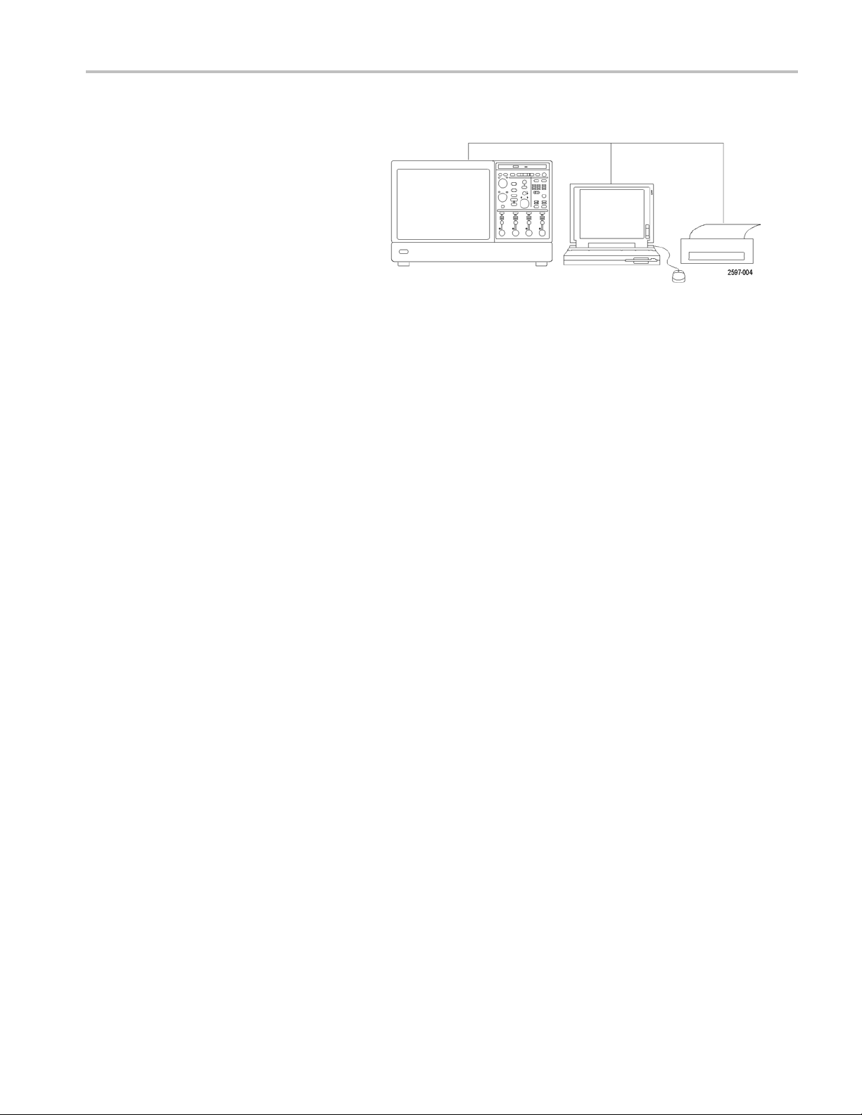
Using the Extended Desktop and OpenChoice Architecture for EfficientDocumentation ................................. 163
Triggeringon Buses........................................................................................................... 165
Triggeringon a Video Signal.................................................................................................. 166
Correlating Data Between a Tektronix Oscilloscope and Logic Analyzer................................................... 168
Cleaning....................................................................................................................... 169
Obtaining the Latest Oscilloscope Application andVersionReleases...................................................... 170
TPP0500 and TPP1000 500 MHz and 1 GHz 10X Passive Probes Instructions........................................... 171
Operating Information......................................................................................................... 171
Connecting the Probe to the Oscilloscope................................................................................... 171
Compensating the Probe ..................................................................................................... 172
Standard Accessories......................................................................................................... 172
Optional Accessories ......................................................................................................... 174
Replacing the Probe Tip...................................................................................................... 174
Specifications.................................................................................................................. 174
Performance Graphs.......................................................................................................... 175
Safety Summary .............................................................................................................. 176
s
MSO70000/C, DPO/DSA70000B/C, DPO7000, and MSO/DPO5000 Series User Manual iii
Page 11

Table of Content
Appendix............................................................................................................................ 178
Index
s
P6616 General-
Product Description ........................................................................................................... 178
Connecting the Probe to the Oscilloscope................................................................................... 179
Connecting th
Functional Check.............................................................................................................. 180
TypicalApplication ............................................................................................................ 181
Accessories
Specifications.................................................................................................................. 182
Safety Summary .............................................................................................................. 183
Safety Term
ContactingTektronix .......................................................................................................... 184
Warranty Information.......................................................................................................... 184
Purpose Logic Probe Instructions .......................................................................... 178
e Probe to Your Circuit ........................................................................................ 180
................................................................................................................... 181
s andSymbols in ThisManual................................................................................... 183
iv MSO70000/C, DPO/DSA70000B/C, DPO7000, and MSO/DPO5000 Series User Manual
Page 12

General Safety S
ummary
General Safet
Review the following safety precautions to avoid injury and prevent damage to this product or any products connected to it.
To avoid potential hazards, use this product only as specified.
Only qualified personnel should perform service procedures.
While using this product, you may need to access other parts of a larger system. Read the safety sections of the other
component manuals for warnings and cautions related to operating the system.
To Avoid Fire or Personal Injury
Use proper power cord. Use only the power cord specified for this product and certified for the country of use.
Connect and disconnect properly. Do not connect or disconnect probes or test leads while they are connected
to a voltag
Ground th
shock, the grounding conductor must be connected to earth ground. Before making connections to the input or output
terminals of the product, ensure that the product is properly grounded.
Observe all terminal ratings. Toavoid fire or shock hazard, observe all ratings and markings on the product. Consult the
product
Connect
e source.
e product.
manual for further ratings information before making connections to the product.
the probe reference lead to earth ground only.
y Summary
This product is grounded through the grounding conductor of the power cord. To avoid electric
Power di
must remain accessible to the user at all times.
sconnect.
The power cord disconnects the product from the power source. Donot block the power cord; it
Do not operate without covers. Do not operate this product with covers or panels removed.
Do not operate with suspected failures. If you suspect that there is damage to this product, have it inspected by
qualified service personnel.
Avoid exposed circuitry. Do not touch exposed connections and components when power is present.
Do not operate in wet/damp conditions.
Do not operate in an explosive atmosphere.
Keep product surfaces clean and dry.
Provide proper ventilation.
per ventilation.
pro
Refer to the manual’s installation instructions for details on installing the product so it has
MSO70000/C, DPO/DSA70000B/C, DPO7000, and MSO/DPO5000 Series User Manual v
Page 13
General Safety S
Terms in This Manual
These terms may appear in this manual:
WARNING. Warning statements identify conditions or practices that could result in injury or loss of life.
CAUTION. Caution statements identify conditions or practices that could result in damage to this product or other property.
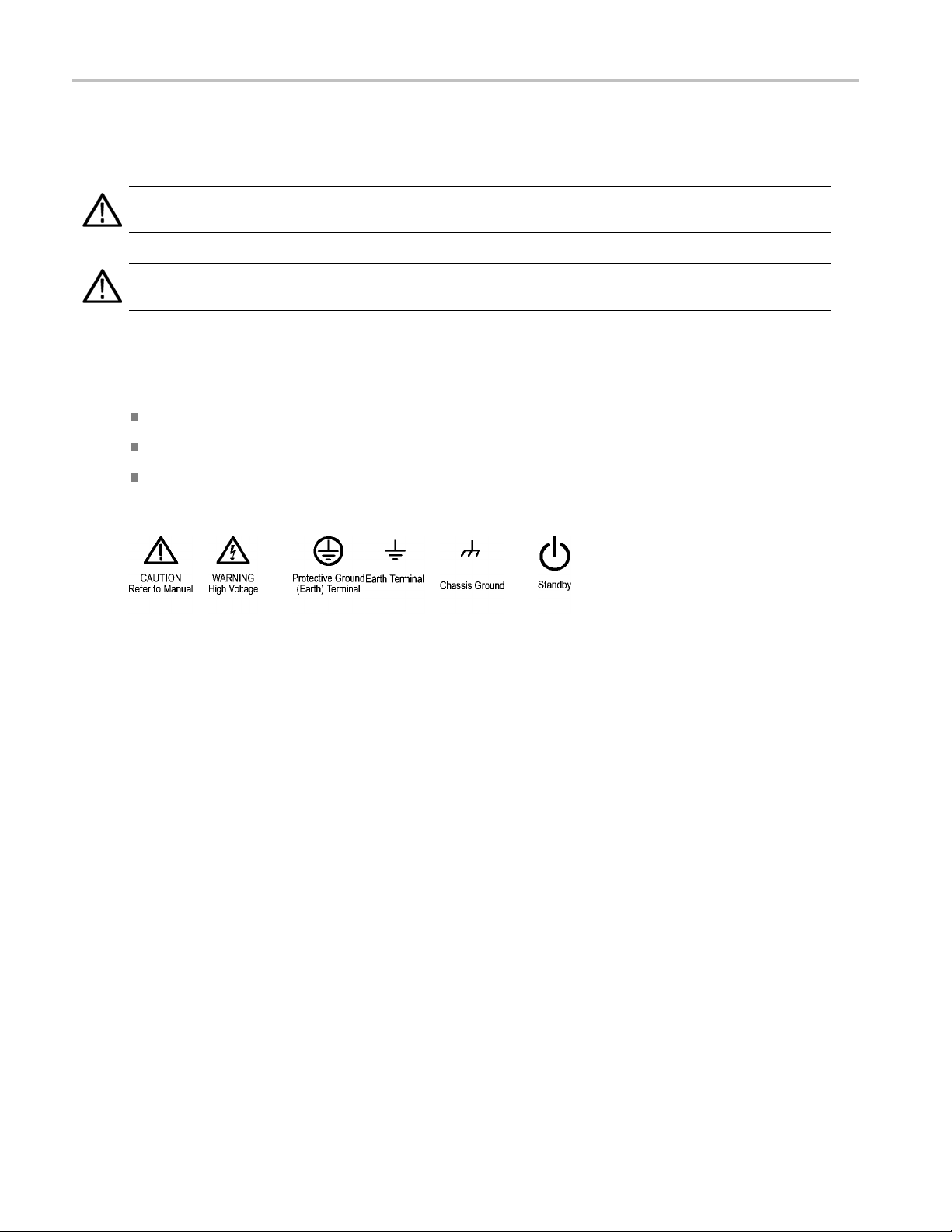
Symbols and Terms on the Product
These terms may appear on the product:
DANGER indicates an injury hazard immediately accessible as you read the marking.
WARNING indicates an injury hazard not immediately accessible as you read the marking.
CAUTION indicates a hazard to property including the product.
The following symbol(s) may appear on the product:
ummary
vi MSO70000/C, DPO/DSA70000B/C, DPO7000, and MSO/DPO5000 Series User Manual
Page 14

Compliance Info
rmation
Compliance In
This section lists the EMC (electromagnetic compliance), safety, and environmental standards with which the instrument
complies.
EMC Compliance
EC Declaration of Conformity – EMC
Meets intent of Directive 2004/108/EC for Electromagnetic Compatibility. Com
specifications as listed in the Official Journal of the European Communities:
EN 61326-1:2006, EN 61326-2-1:2006. EMC requirements for electrical equipment for measurement, control, and
laboratory use.
CISPR 11:2003. Radiated and conducted emissions, Group 1, Class A
IEC 61000-4-2:2001. Electrostatic discharge immunity
IEC 61000-4-3:2002. RF electromagnetic field immunity
IEC 61000-4-4:2004. Electrical fast transient/burst immunity
IEC 61000-4-5:2001. Power line surge immunity
IEC 61000-4-6:2003. Conducted RF immunity
IEC 61000-4-11:2004. Voltage dips and interruptions immunity
123
formation
pliance was demonstrated to the following
4
4
5
EN 61000-3-2:2006. AC power line harmonic emissions
EN 61000-3-3:1995. Voltage changes, fluctuations, and flicker
European contact.
Tektronix UK, Ltd.
Western Peninsula
Western Road
Bracknell, RG12 1RF
United Kingdom
1
This product is intended for use in nonresidential areas only. Use in residential areas may cause electromagnetic interference.
2
Emissions which exceed the levels required by t his standard may occur when this equipment is connected to a test object.
3
If interconnect cables are used, they must be low–EMI shielded cables such as t he following Tektronix part numbers or their
equivalents: 012-0991-01, 012-0991-02 or 0 12-0991-03 GPIB Cable; 012-1213-00 (or CA part number 0294-9) RS-232 Cable;
012-1214–00 Centronics Cable; or LCOM part number CTL3VGAMM-5 VGA Cable. Use an 012-0482-00 cable for the Ref O ut connector.
4
The performance criterion for when the oscilloscope is subjected to the continuously present electromagnetic phenomenon:
MSO70000/C, DSA70000/C, DPO70000/C, and DPO7000: 1 0 mV/division to 1 V/division: ≤0.4 division waveform displacement
or ≤0.8 division increase in peak–to–peak noise. Performa
electromagnetic phenomenon: Temporary, self–recoverable degradation or loss of performance is allowed, but no change of actual
operating state or loss of stored data is allowed.
MSO5000 and DPO5000: ≤4.0 division waveform displacement or ≤8.0 division increase in peak–to–peak noise. Performance
criterion for when the oscilloscope is subjected t o transient electromagnetic phenomenon: Temporary, self–recoverable degradation
or loss of perform ance is allowed, but no change of actual operating state or loss of stored data is allowed.
5
Performance Criterion C applied at the 70%/25 cycle Voltage-Dip and the 0%/250 cycle Voltage-Interruption test levels (IEC
61000-4-11). If the instrument powers down upon a voltage dip or interruption it will take longer than ten seconds to reboot.
nce criterion for when the oscilloscope is subjected to transient
MSO70000/C, DPO/DSA70000B/C, DPO7000, and MSO/DPO5000 Series User Manual vii
Page 15

Compliance Info
Australia / New Zealand Declaration of Conformity – EMC
Complies with the EMC provision of the Radiocommunications Act per the following standard, in accordance with ACMA:
CISPR 11:2003. Radiated and Conducted Emissions, Group 1, Class A, in accordance with EN 61326-1:2006 and
EN 61326-2-1:2006.
Australia / New Zealand contact.
Baker & McKenzie
Level 27, AMP Centre
50 Bridge St
Sydney NSW 2000, Australia
rmation
reet
viii MSO70000/C, DPO/DSA70000B/C, DPO7000, and MSO/DPO5000 Series User Manual
Page 16

Safety Compliance
EC Declaration of Conformity – Low Voltage
Compliance was demonstrated to the following specification as listed in the Official Journal of the European Communities:
Low Voltage Directive 2006/95/EC.
EN 61010-1: 2001. Safety requirements for electrical equipment for measurement control and laboratory use.
Compliance Info
rmation
U.S. Nation
UL 61010-1:2004, 2ndEdition. Standard for electrical measuring and test equipment.
ally Recognized Testing Laboratory Listing
Canadian Certification
CAN/CSAlaboratory use. Part 1.
C22.2 No. 61010-1:2004. Safety requirements for electrical equipment for measurement, control, and
Additional Compliances
IEC 61010-1: 2001. Safety requirements for electrical equipment for m easurem ent, control, and laboratory use.
Equipment Type
Test and measuring equipment.
y Class
Safet
Class 1 – grounded product.
Pollution Degree Description
asure of the contaminants that could occur in the environment around and within a product. Typically the internal
Ame
environment inside a product is considered to be the same as the external. Products should be used only in the environment
for which they are rated.
Pollution Degree 1. No pollution or only dry, nonconductive pollution occurs. Productsin this category are generally
capsulated, hermetically sealed, or located in clean rooms.
en
llution Degree 2. Normally only dry,nonconductive pollution occurs. Occasionally a temporary conductivity that is
Po
caused by condensation must be expected. This location is a typical office/home environment. Temporarycondensation
occurs only w hen the product is out of service.
Pollution Degree 3. Conductive pollution, or dry,nonconductive pollution that becomes conductive due to condensation.
hese are sheltered locations where neither temperature nor humidity is controlled. The area is protected from direct
T
sunshine, rain, or direct wind.
Pollution Degree 4. Pollution that generates persistent conductivity through conductive dust, rain, or snow. Typical
outdoor locations.
MSO70000/C, DPO/DSA70000B/C, DPO7000, and MSO/DPO5000 Series User Manual ix
Page 17

Compliance Info
Pollution Degree
Pollution Degree 2 (as defined in IEC 61010-1). Note: Ratedfor indoor use only.
Installation (Overvoltage) Category Descriptions
Terminals on this product may have differentinstallation (overvoltage) category designations. The installation categories are:
Measurement Category IV. For measurements performed at the source of low-voltage installation.
Measurement Category III. For measurements performed in the building installation.
Measurement Category II. For measurements performed on circuits directly connected to the low-voltage installation.
Measurement Category I. For measurements performed on circuits not directly connected to MAINS.
rmation
Overvolta
Mains: Overvoltage Category II
Measurement inputs:
MSO5000, DPO5000, and DPO7000 instruments in 50 Ohm mode and MSO70000/C, DSA70000B/C, and DPO70000B /C
instruments are CAT 1 with no impulse allowed.
DPO7000 instruments are CAT 1 in 1 Meg-Ohm mode.
MSO5000 and DPO5000 instruments are CAT II in 1 Meg-Ohm mode.
(As defined in IEC 61010-1)
ge Category
x MSO70000/C,DPO/DSA70000B/C, DPO7000, and MSO/DPO5000 Series User M anual
Page 18

Environmental Considerations
This section provides information about the environmental impact of the product.
Product End-of-Life Handling
Observe the following guidelines when recycling an instrument or component:
Equipment recycling. Productionof this equipment required the extraction and use of natural resources. The equipment
may contain substances that could be harmful to the environment or human health if improperly handled at the product’s
end of life. To avoid release of such substances into the environment and to reduce the use of natural resources, we
encourage you to recycle this product in an appropriate system that will ensure that most of the materials are reused
or recycled appropriately.
This symbol indicates that this product complies with the applicable European Union requirements according
to Directives 2002/96/EC and 2006/66/EC on waste electrical and electronic equipment (WEEE) and
batteries. For information about recycling options, check the Support/Service section of the Tektronix Web
site (www.tektronix.com).
Compliance Info
rmation
Mercury n
to environmental considerations. Please contact your local authorities or, within the United States, refer to the E-cycling
Central Web page (www.eiae.org) for disposal or recycling information.
1
otification1.
This notification does not apply to MSO5000 and DPO5000 instruments. MSO5000 and DPO5000 instruments use an LED backlight
that does not contain mercury.
This product uses an LCD backlight lamp that contains mercury. Disposal may be regulated due
Perchlorate materials. This product contains one or more type CR lithium batteries. According to the state
of California, CR lithium batteries are classified as perchlorate materials and require special handling. See
www.dtsc.ca.gov/hazardouswaste/perchloratefor additional information.
Restriction of Hazardous Substances
roduct is classified as Monitoring and C ontrol equipment, and is outside the s cope of the 2002/95/EC RoHS Directive.
This p
MSO70000/C, DPO/DSA70000B/C, DPO7000, and MSO/DPO5000 Series User Manual xi
Page 19

Preface
Preface
This manual describes the installation and operation of MSO70000B/C Series, DSA70000B/C Series, DPO70000B/C Series,
DPO7000 Series, MSO5000 Series, and DPO5000 Series instruments. Basic operations and concepts are presented in this
manual. For more detailed information see the online help on your instrument. The following instruments are supported by
this manual:
DPO72004C, DSA72004C and MSO72004C
DPO71604C, DSA71604C and MSO71604C
DPO71254C, DSA71254C and MSO71254C
DPO70804B, DSA70804B and MSO70804
DPO70604B, DSA70604B and MSO70604
DPO70404B, DSA70404B and MSO70404
DPO7354
DPO7254
DPO7104
DPO7054
MSO5204 and DPO5204
MSO5104 and DPO5104
MSO5054 and DPO5054
MSO5034 and DPO5034
Key Features
MSO70000/C, DSA70000B/C, DPO70000B/C, DPO7000, MSO5000, and DPO5000 Series instruments can help you verify,
debug, and characterize electronic designs. Key features include:
20 GHz bandwidth and 100 GS/s real time sampling rate on 2 analog channels, MSO72004C, DSA72004C, and
DPO72004C
16 GHz bandwidth and 100 GS/s real time sampling rate on 2 analog channels, MSO71604C, DSA71604C, and
DPO71604C
12.5 GHz bandwidth and 100 GS/s real time sampling r ate on 2 analog channels, MSO71254C, DSA71254C, and
DPO71254C
8 GHz bandwidth and 25 GS/s real time sampling rate on analog channels, DPO70804B, DSA70804B, and MSO70804
6 GHz bandwidth and 25 GS/s real time sampling rate on analog channels, DPO70604B, DSA70604B, and MSO70604
4 GHz bandwidth and 25 GS/s real time sampling rate on analog channels, DPO70404B, DSA70404B, and MSO70404
3.5 GHz bandwidth and 10 GS/s real time sampling rate on all channels, 40 GS/s on 1 channel, DPO7354
2.5 GHz bandwidth and 10 GS/s real time sampling rate on all channels, 40 GS/s on 1 channel, DPO7254
xii MSO70000/C,DPO/DSA70000B/C, DPO7000, and MSO/DPO5000 Series User M anual
Page 20

Preface
1 GHz bandwidth and 5 GS/s (10 GS/s optional) real time sampling rate on all channels, 20 GS/s (40 GS/s optional)
on 1 channel, DP
500 MHz bandwidth and 5 GS/s real time sampling r ate on all channels, 20 GS/s on 1 channel, DP O7054
2 GHz bandwidth and 10 GS/s real time sampling rate on 2 analog channels, MSO5204 and DPO5204
1 GHz bandwidth and 10 GS/s real time sampling rate on 2 analog channels, MSO5104 and DPO5104
500 MHz bandwidth and 5 GS/s real time sampling rate on all analog channels, MSO5054 and DPO5054
350 MHz bandwidth and 5 GS/s real time sampling rate on all analog channels, MSO5034 and DPO5034
Enhanced Bandwidth capability that, when enabled, applies Digital Signal Processing (DSP) filters that can extend the
bandwidth and flatten the passband. Enhanced Bandwidth provides a matched response across enabled channels when
they are at maximum sample rate. Youcan limit the bandwidth down to 500 MHz to optimize the signal to noise ratio.
Enhanced bandwidth is extended to the probe tip for some high performance probes and tips.
Record lengths up to 500,000,000 samples, depending on model and option
Up to 1.0% DC vertical gain accuracy, depending on model
Four analog input channels (each with 8-bit resolution when not in Hi-Res mode), auxiliary trigger input and output
Sixteen digital channels available on MSO70000/C and MSO5000 Series instruments with an additional clock channel
available on the MSO70000/C
O7104
iCapture allows analyzing the analog characteristics of the digital channels on MS O70000/C Series instruments
Sample, envelope, peak-detect, high-resolution, waveform database, average, and FastAcq acquisition modes
Full programmability,with an extensive GPIB-command set and a message-based interface
PinPoint triggering with flexible A and B tr
DSA70000B/C, DPO70000B/C, and DPO7000/C
Complete set of triggers available on MSO5000 and DPO5000 Series instruments
Selectable trigger position correction to more accurately place the trigger and reduce jitter.
Serial triggering on industry standards, serial pattern triggering, and pattern lock triggering are available on some
models or options.
Parallel trigger available on MSO70000/C and MSO5000 Series instruments.
Powerful built-in measurement capability, including histograms, automatic measurements, eye pattern measurements
and measurement statistics
Mathematically combine waveforms to create waveforms that support your data-analysis task. Use arbitrary filters in
math equations. Use spectral analysis to analyze waveforms in the frequency domain.
A large 12.1 inch (307.3 mm) [10.4 inch (264 mm) MSO5000 and DPO5000] high resolution XGA color display that
supports color grading of waveform data to show sampl
Wave Inspector controls for managing long record length, with zoom and pan, play and pause, and search and mark
available on MSO5000 and DPO5000
igger events and logic qualified triggers available on MSO70000/C,
e density. Display 10 divisions both horizontally and vertically.
MagniVu 60.6 ps resolution, high-speed digital sampling rate on M SO5000
MultiView Zoom to view and compare up to four zoom areas at a time. Lock and manually or automatically scroll up to
four zoom areas. You can control the visibility of waveforms inside the zoom window
Automatically search and mark events of interest on your waveform
MSO70000/C, DPO/DSA70000B/C, DPO7000, and MSO/DPO5000 Series User Manual xiii
Page 21
Preface
Automatic DDR analysis using the DDR Memory Technology Analysis option
Customizable MyScope control windows
Ability to control sample rate and record length separately from horizontal scale
An intuitive, graphical user interface (UI), with online help that is built in and available on screen
Internal, removable disk storage
Wide array of probing solutions
Documentat
Review the following for the location of different types of information available for this product.
To read about Use these documents
Installation and Operation (overviews) User Manual. Provides general operating information.
In-Depth Operation and User Interface Help Online Help. Provides detailed instructions for using instrument functions.
Programmer Commands Programmer guide (on the documentation browser or available on-line at
Service Information Service manual (on the documentation browser or available on-line at
ion
Conventions Used in This Manual
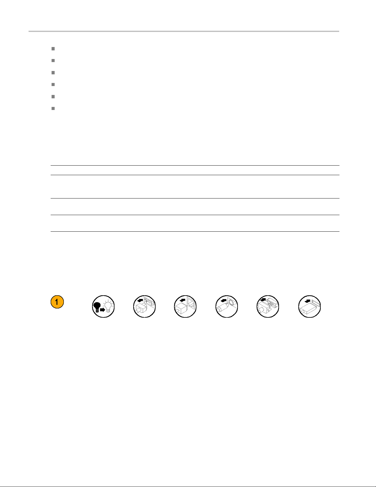
The following icons are used throughout this manual.
panel
Sequence
Step
Front
power
Connect
power
Access online help from the Help button or Help menu for information on
controls and elements on screen. (See page 25, Accessing Online Help.)
www.tektronix.com/manuals). Includes the syntax of the GPIB commands.
www.tektronix.com/manuals).
rk
Netwo
PS-2 SVGA USB
xiv MSO70000/C,DPO/DSA70000B/C, DPO7000, and MSO/DPO5000 Series User Manual
Page 22

Install Your Instrument
Unpack the instrument and check that you received all items listed as Standard Accessories. Recommendedaccessories,
probes, instrument options, and upgrades are listed in the online help. Checkthe TektronixWeb site (www.tektronix.com)
for the most current information.
Standard Accessories
Accessory Tektronix part number
MSO70000/C, DSA70000B/C, DPO70000B/C, DPO7000, MSO5000, and
DPO5000 Series Digital Phosphor Oscilloscopes User Manual
Product Software DVD, MSO70000/C, DSA70000B/C, DPO70000B/C, and
DPO7000 series
Operating System Restore D VD, MSO70000/C, DSA70000B/C,
DPO70000B/C, and DPO7000 Series
Online Help (part of the product software)
Performance Verification (on the documentation browser)
Programmer Online Guide (on the documentation browser)
NIST, Z540-1, and ISO9000 Calibration Certificate
One TekConnectadapter, ≥4 GHz models only TCA-BNC
Four TekConnect adapters, ≥4 GHz models only TCA-292MM
One 16-channel digital probe with accessory kit, MSO5000 models only
One passive probe per channel, MSO5204, MSO5104, DPO5204, and
DPO5104
One passive probe per channel, MSO5054, MSO5034, DPO5054, and
DPO5034
Touchscreen stylus, MSO5000 and DPO5000
NI SignalExpress software, MSO5000 and DPO5000
Keyboard, ≥4 GHz models only
Mouse, optical 119-7054-xx
Front Cover, MSO5000 and DPO5000
All other models
Wrist Strap, ≥4 GHz models only
Accessory Pouch
≥4GHzmodels
DPO7000 models
MSO5000 and DPO 5000 models
Nero OEM Software CD, ≥4 GHz and DPO7000 models
071-2790-xx
020-3026-xx
020-3019-xx
—
077-0063-xx
077-0010-xx
—
P6616
TPP1000
TPP0500
119-6107-xx
063-3967-xx
119-7083-xx
200-5052-xx
200-4963-xx
006-3415-05
016-1441-xx
016-1966-xx
016-2029-xx
063-3781-xx
Install Your Ins
trument
MSO70000/C, DPO/DSA70000B/C, DPO7000, and MSO/DPO5000 Series User Manual 1
Page 23
Install Your Ins
Accessory Tektronix part number
Power Cord
trument
One of the following: MSO5000
and DPO5000
models
North America (Option A0)
Universal Euro (Option A1)
United Kingdom (Option A2)
Australia (Option A3)
North America 240 V (Option A4)
Switzerland (Option A5)
Japan (Option A6)
Option A10)
China (
(Option A11)
India
l (Option A12)
Brazi
wer cord or AC adapter (Option A99)
No po
161-0348-00 161-0104-00 161-0213-00
161-0343-00 161-0104-06 161-0209-00
161-0344-0
161-0346-0
—
161-0347-
161-0342
161-0341-00 161-0306-00 161-0352-00
161-0349-00 161-0324-00 161-0325-00
161-xxxx-00 161-0356-00 161-0358-00
———
00
-00
0
0
DPO7000
models
161-0104-0
161-0104-1
161-0104161-0167161-A005
08
00
-00
7
4
≥4GHz
models
161-0210-0
161-0211-0
—
161-0212161-0213
Notice: Do
not use the
provide
power cord
for other
product
-00
d
s.
0
1
00
Operating Requirements
MSO70000/C, DSA70000B/C, DPO70000B/C, and DPO7000
1. Place the instrument on a cart or bench.
The instrument should rest on its bottom
or rear feet. An optional rack mounting
kit is available. Observe the following
clearance requirements and dimensions:
Top:
Left and right side: 0 in (0 mm) on right side
Bottom:
Rear:
<4 GHz Models ≥4 GHz Models
0in(0mm) 0in(0mm)
3in(76mm)
3 in (76 mm) on left side
0 in (0 mm) standing on feet, flip
stands down
0 in (0 mm) on rear feet 0 in (0 mm) on rear feet
0 in (0 mm) standing on feet, flip
stands down
2 MSO70000/C, DPO/DSA70000B /C, D PO7000, and MSO /DP O5000 Series User Manual
Page 24

Install Your Ins
trument
2. Width:
3. Height:
4. Before opera
ting the instrument, verify
17.96 inches (
10.9 inches (2
5°Cto+45°C(
456 mm)
77 mm)
+41°Fto+113°F)
the ambient temperature:
5. Verify the operating humidity: 8% to 80% relative humidity with
a maximum wet-bulb temperature
of +29 °C (+8
4 °F) at or below
+45 °C (+113°F), noncondensing
Upper limit derated to 30% relative
t +45 °C (+113°F)
els: 3,000 m
6. Verify th
e operating altitude:
humidity a
<4 GHz mod
(9,843 feet)
7. Maximum input voltage, <4 GHz models:
5V
50 Ω
1MΩ
, with peaks ≤±24 V.
RMS
150 V,derate at 2 0 dB/decade to 9 V
oltage at the BNC, between center conductor and ground is
input v
400V peak. The RMS voltage is limited to <150 V for arbitrary waveshapes
including DC. The maximum pulse width for impulses with peaks over
s50μs. Example: At 0 V to 400 V peak, rectangular wave, the duty
150Vi
factor is 14%. The maximum transient withstand voltage is ±800 V peak.
17.75 inches (
11.48inches (
5°Cto+45°C(
451 mm)
292 mm)
+41°Fto+113°F)
8% to 80% relative humidity at up
to+32°C(+90°F)
5% to 45% rel
ative humidity above
+32 °C (+90 °F) up to +45 °C
(+113 °F), noncondensing, and
is limited
by a maximum wet-bulb
temperature of +29.4 °C (+85 °F)
(derates relative humidity to 32%
at +45 °C (
≥4GHzmod
+113°F))
els: 3,000 m
(9,843 feet), derate maximum
operating temperature by 1 °C
per 300 m
eters (984.25 feet)
above 1500 meters (4921.25 feet)
altitude.
above 200 kHz. Themaximum
RMS
MSO70000/C, DPO/DSA70000B/C, DPO7000, and MSO/DPO5000 Series User Manual 3
Page 25
Install Your Ins
trument
Maximum input
50 Ω <1 V
Maximum nondestructive input voltage to
logic probes
voltage, ≥4 GHz models:
, MSO70000 Series:
±15 V
RMS
/FS settings and < 5.5 V
for <1 V
for ≥1 V/FS settings.
RMS
CAUTION. For proper cooling, keep the bottom and sides of the instrument clear of obstructions.
MSO5000 and DPO5000
1. Place the instrument on a cart or bench.
The instrument should rest on its bottom
or rear feet. An optional rack mounting
kit is available. Observe the following
clearance requirements and dimensions:
Rear:
Left side: 2 in (50.8 mm)
2. Width:
3. Height:
4. Before operating the instrument, verify
the ambient temperature:
5. Verify the operating humidity: High: 40 °C to 50 °C (104 °F to 122 °F), 10% to 60% relative humidity
6. Verify the
operating altitude:
7. Maximum input voltage:
50 Ω input impedance
1MΩ input
Maximum
impedance
nondestructive input voltage to
logic probes:
2in(50.8mm)
17.3 inches (4
9.2 inches (2
39 mm)
33 mm) including feet
10.7 inches (272 mm) including vertical handle and feet
5°Cto+50°C(+41°Fto+131°F)
Low: 0 °C to 4
3,000 m (9,
5V
RMS
300 V
RMS
0 °C (32 °F to 104 °F), 10% to 90% relative humidity
843 feet)
, with peaks ≤±20 V (DF ≤6.25%).
ith peaks ≤±425 V at the BNC.
w
For <100 mV/div derate at 20 dB/decade above 100 kHz to 30 V
1 MHz, 10 dB/decade above 1 MHz.
For ≥100
mV/div derate at 20 dB/decade above 3 MHz to 30 V
30 MHz, 10 dB/decade above 30 MHz.
±42 V
RMS
RMS
at
at
CAUTIO
N. For proper cooling, keep the back and left side of the instrument clear of obstructions.
4 MSO70000/C, DPO/DSA70000B /C, D PO7000, and MSO /DP O5000 Series User Manual
Page 26
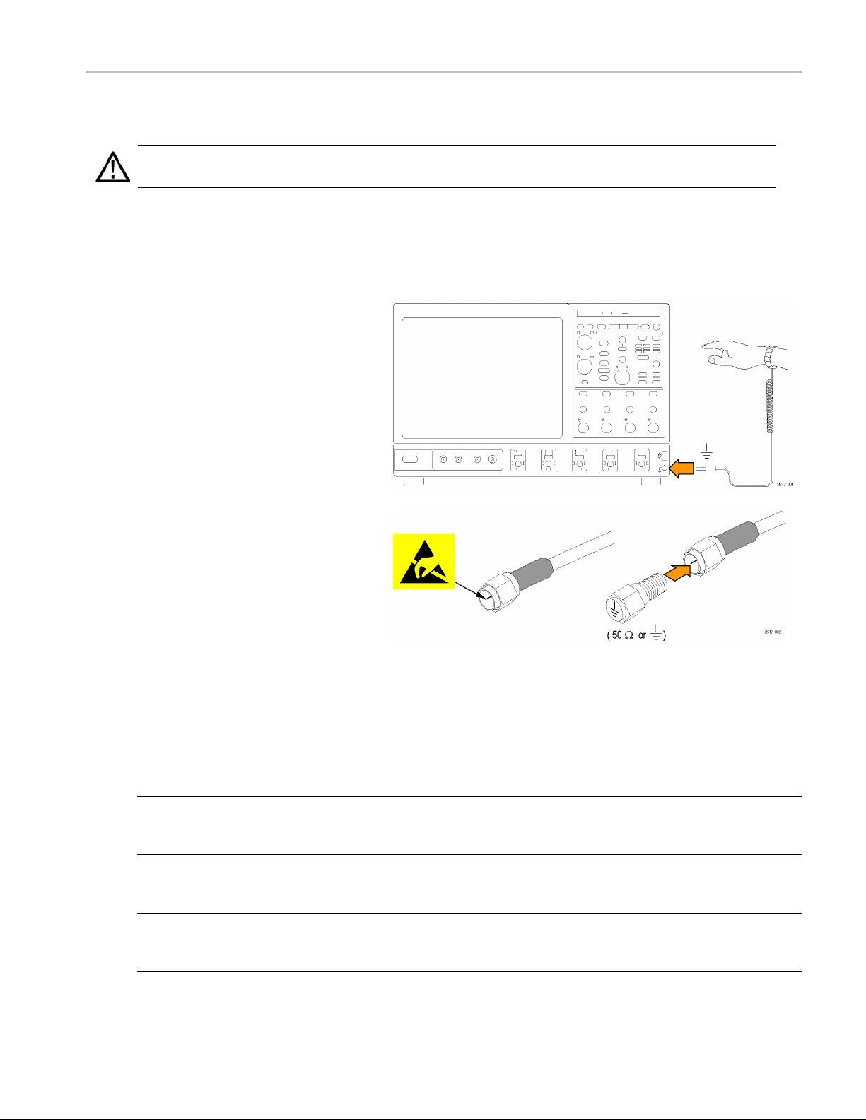
Preventing ESD
Install Your Ins
trument
CAUTION. Adir
ect electrostatic discharge can damage the instrument input. To learn how to avoid this damage, read
the following information.
Electrostatic discharge (ESD) is a concern when handling any electronic equipment. The instrument is designed with
robust ESD protectio
n, however it is still possible that large discharges of static electricity directly into the signal input
may damage the instrument. To avoid damage to the instrument, use the following techniques to prevent electrostatic
discharge to the instrument.
1. Discharge the static voltage from your
body by wearing a grounded antistatic
wrist strap while connecting and
disconnecting cables and TekConnect
adapters. The instrument provides a
front panel connection for this purpose.
2. A cable that is left unconnected on
a bench can develop a large static
charge. Discharge the static voltage
from all cables before connecting them
to the instrument or device under test
by momentarily grounding the center
conductor of the cable, or by connecting
a50Ω termination to one end, before
attaching the cable to the instrument.
Powering On the Instrument
Power supply requirements
Source voltage and frequency Power consumption
MSO70000/C, DSA70000B/C, and DPO70000B/C Series:
100–240 V
or 115 V
±10%, 50–60 Hz
RMS
±10%, 400 Hz. CAT II
RMS
DPO7000 Series:
100–240 V
or 115 V
±10%, 47–63 Hz
RMS
±10%, 400 Hz
RMS
MSO5000 and DPO5000 Series:
100–240 V
±10% 50–60 Hz
RMS
115V440Hz
MSO70000/C, DPO/DSA70000B/C, DPO7000, and MSO/DPO5000 Series User Manual 5
≤1100 VA
550 Watts maximum
275 Watts maximum
Page 27
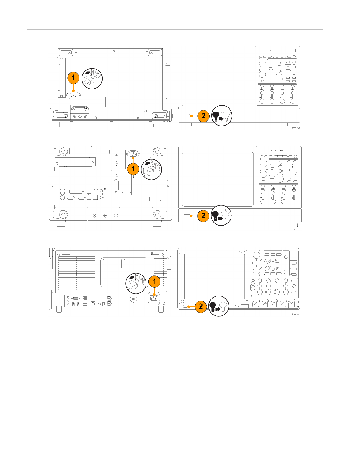
Install Your Ins
DPO7000 Series
trument
MSO70000/C, DSA70000B/C, and D PO70000B/C Series
MSO5000 and DPO5000 Series
6 MSO70000/C, DPO/DSA70000B /C, D PO7000, and MSO /DP O5000 Series User Manual
Page 28
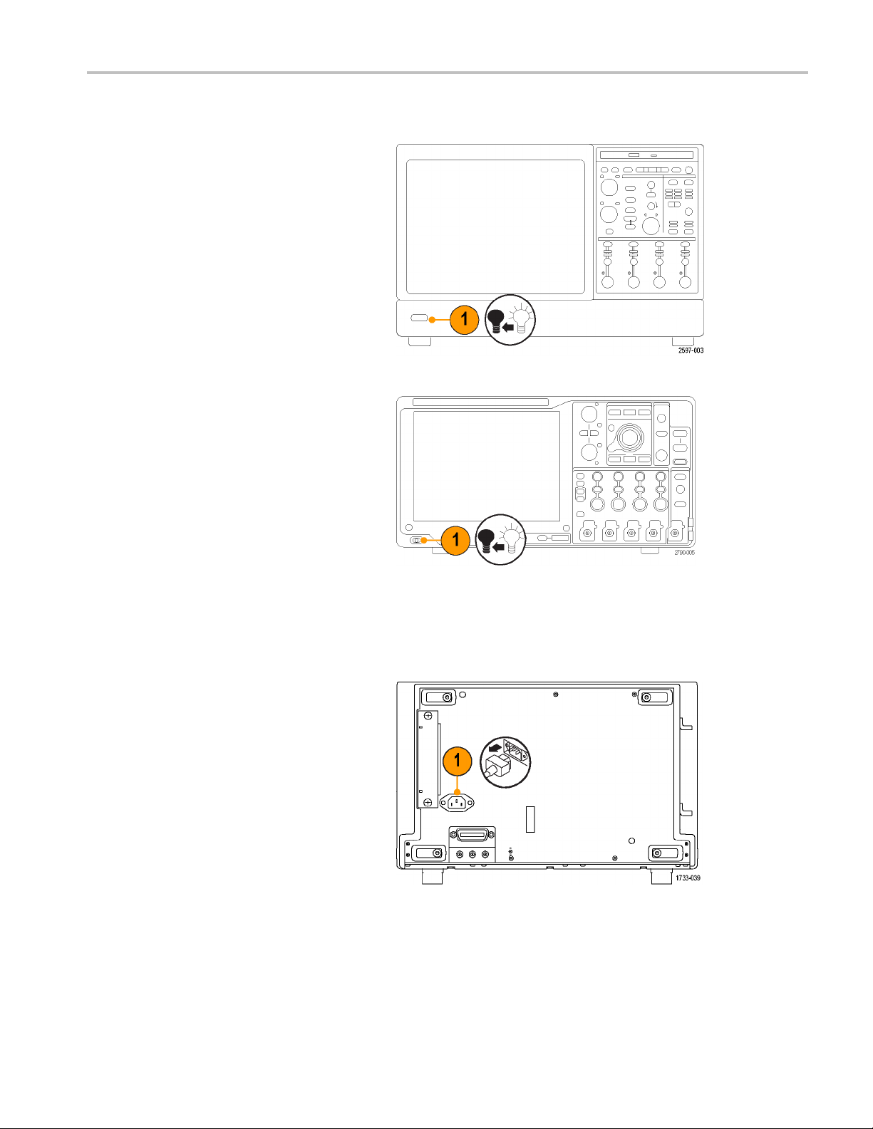
Powering Off the Instrument
Install Your Ins
MSO70000/C, DSA70000B/C, DPO70000B/C, and DPO7000 Series
trument
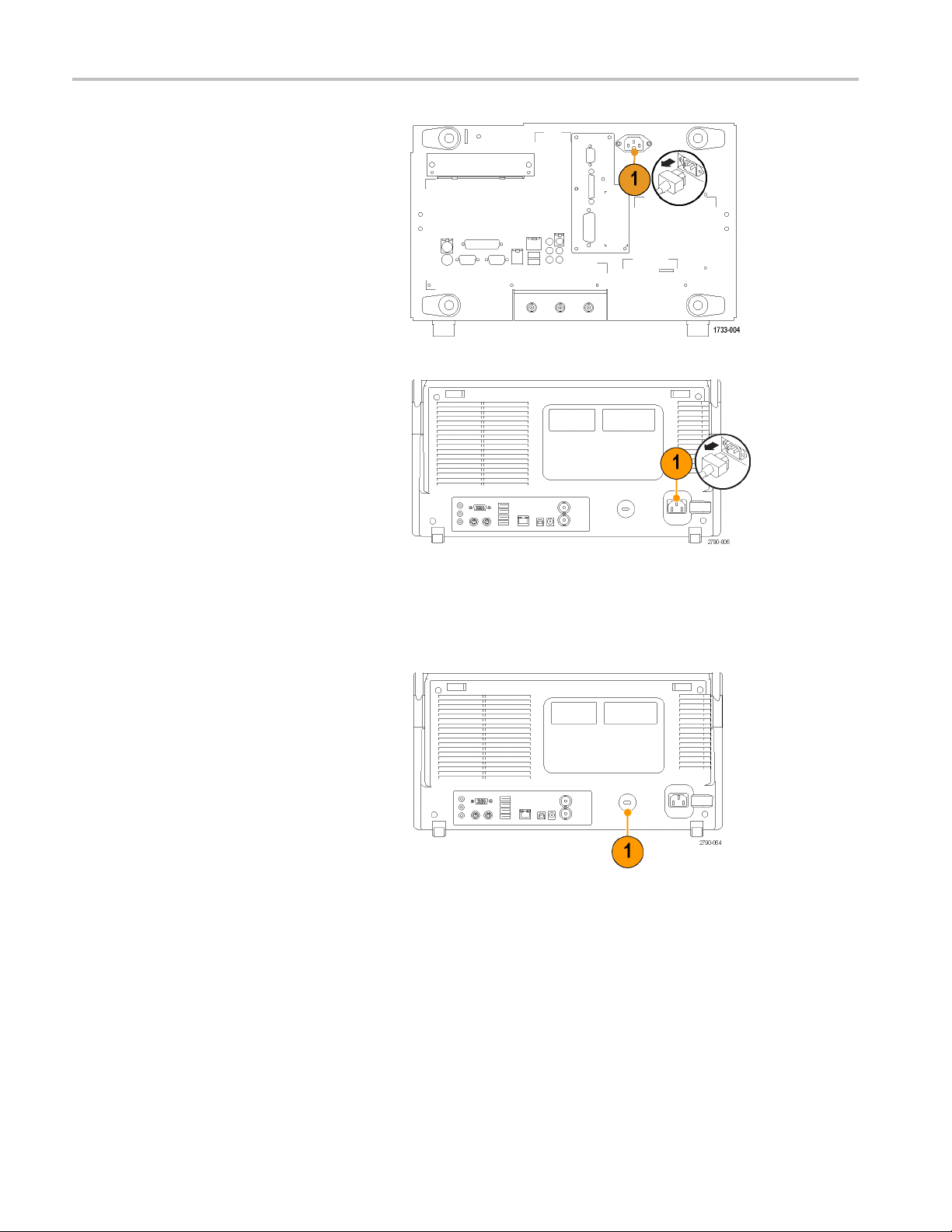
Removing the Power
MSO5000 and DPO5000 Series
DPO7000 Series
MSO70000/C, DPO/DSA70000B/C, DPO7000, and MSO/DPO5000 Series User Manual 7
Page 29
Install Your Ins
trument
Securing the Oscilloscope
1. Use a standard laptop computer-style
security lock to secure your oscilloscope
to your location.
MSO70000C,
MSO5000 and DPO5000 Series
DSA70000B/C, and DPO70000B/C Series
MSO5000 and DPO5000 Series
8 MSO70000/C, DPO/DSA70000B /C, D PO7000, and MSO /DP O5000 Series User Manual
Page 30
Connecting to a Network
Install Your Ins
trument
Connect your i
printing, file sharing, internet access, and
other functions. Consult with your network
administrato
utilities to configure the instrument for your
network.
Use the Remot
Windows to control and view the instrument
remotely.
nstrument to a network for
r and use the standard W indows
e Desktop Connection of
MSO70000/C, DPO/DSA70000B/C, DPO7000, and MSO/DPO5000 Series User Manual 9
Page 31

Install Your Ins
trument
Adding a Second Monitor
You can operate the instrument while using Windows and installed applications on an external monitor. Follow the procedure
below to set up a dual monitor configuration.
MSO70000/C, DSA70000C, and DPO70000C Series
1. Turn power off.
2. Connect second monitor. If using a VGA
monitor,use a DVI to VGA adapter.
3. Connect keyboard.
4. Connect mouse.
5. Turn instrument power on.
6. Turn monitor power on.
MSO70000/C, DSA70000C, and DPO70000C Series
10 MSO70000/C, DPO/DSA70000B/C, DPO7000, and MSO /DP O5000 Series U ser Manual
Page 32

DSA70000B and DPO70000B Models
1. Turn power off.
2. Connect second monitor.
3. Connect keyboard.
4. Connect m ouse.
5. Turn instrument power on.
6. Turn monitor power on.
Install Your Ins
trument
DSA70000B and DPO70000B Series
MSO70000/C, DPO/DSA70000B/C, DPO7000, and MSO/DPO5000 Series User Manual 11
Page 33

Install Your Ins
DPO7000 Models
trument
1. Turn off power
2. Connect secon
3. Connect key
4. Connect mou
5. Turn on in
6. Turn on mo
board.
strument power.
nitor power.
.
d monitor.
se.
DPO7000 Series
12 MSO70000/C, DPO/DSA70000B/C, DPO7000, and MSO /DP O5000 Series U ser Manual
Page 34

MSO5000 and DPO5000 Models
1. Turn off power.
2. Connect second monitor.
3. Connect keyboard.
4. Connect m ouse.
5. Turn on instrument power.
6. Turn on monitor power.
Install Your Ins
trument
MSO5000 and DPO5000 models
MSO70000/C, DPO/DSA70000B/C, DPO7000, and MSO/DPO5000 Series User Manual 13
Page 35

Install Your Ins
If your instrument uses Windows XP,
continue with the following steps:
7. Right-click on the Windows desktop, and
trument
then select Pr
operties.
8. Select Sett
ings. Click the grayed out
external monitor ( 2 ), and drag it to the
left of monitor 1.
9. Select Yes when you are prompted to
enable the
10. Click Appl
new monitor.
y.
11. Click Yes to restart your instrument.
14 MSO70000/C, DPO/DSA70000B/C, DPO7000, and MSO /DP O5000 Series U ser Manual
Page 36

Operating System Restore
If your instrument shipped with an operating system restore DVD and you need to restore the operating system, you can
use the procedure that came with the DVD.
The instrument contains an operating system restore file on a separate partition of the hard drive.
The preferred method to restore the instrument operating system is to use the hard d isk restore file.
CAUTION. Using the restore process reformats the hard drive and reinstalls the operating system. All saved data is lost. If
possible, save important files to external media before performing a system restore.
1. Restart the instrument. During the boot-up process you will see the following message at the top of the s creen: Starting
Acronis Loader... press F5 for Acronis S tartup Recovery Manager
2. Repeatedly press the F5 k ey until the Acronis True Image Toolopens. There is a 15-second time period from when the
message appears until the instrument proceeds with the nor mal instrument startup. Ifthe instrument does not open the
Acronis application, power off the instrument, then power on the instrument and try again.
3. Click R estore.
4. In the Confirmation dialog box, click Yes to restore the instrument operating system, or No to exit the restore process.
The restore process takes approximately 30 minutes; the actual time depends on the instrument configuration.
Install Your Ins
trument
Installing the MSO5000 and DPO5000 Hard Drive
CAUTION. Inserting the hard drive
assembly upside down could damage the
instrument.
1. Verify that the instrument is off.
2. Insert the hard drive into the i nstrument
with the drive assembly chassis facing
up.
3. Secure the drive assembly using the
thumb screw.
4. Install the cover.
MSO70000/C, DPO/DSA70000B/C, DPO7000, and MSO/DPO5000 Series User Manual 15
Page 37

Getting Acquain
ted with Your Instrument
Getting Acqua
Front Panel
MSO70000/C, DSA7000B/C, DPO70000B/C, and DPO7000
1. DVD/CD-RW drive
2. Front panel controls
3. USB port
4. Ground terminal
5. Recovered data output (not available on
DPO7104 and DPO7054)
6. Recovered clock output (not available on
DPO7104 and DPO7054)
7. Probe compensation output
8. Probe calibration output
9. Channel 1–4 input
10. Auxiliary Trigger input
inted with Your Instrument
11. Fast Edge output
12. DC Probe Cal output
13. Logic probe input
DPO7000 Series
DSA70000B/C and DPO70000B/C Series
MSO70000/C Series
16 MSO70000/C, DPO/DSA70000B/C, DPO7000, and MSO /DP O5000 Series U ser Manual
Page 38

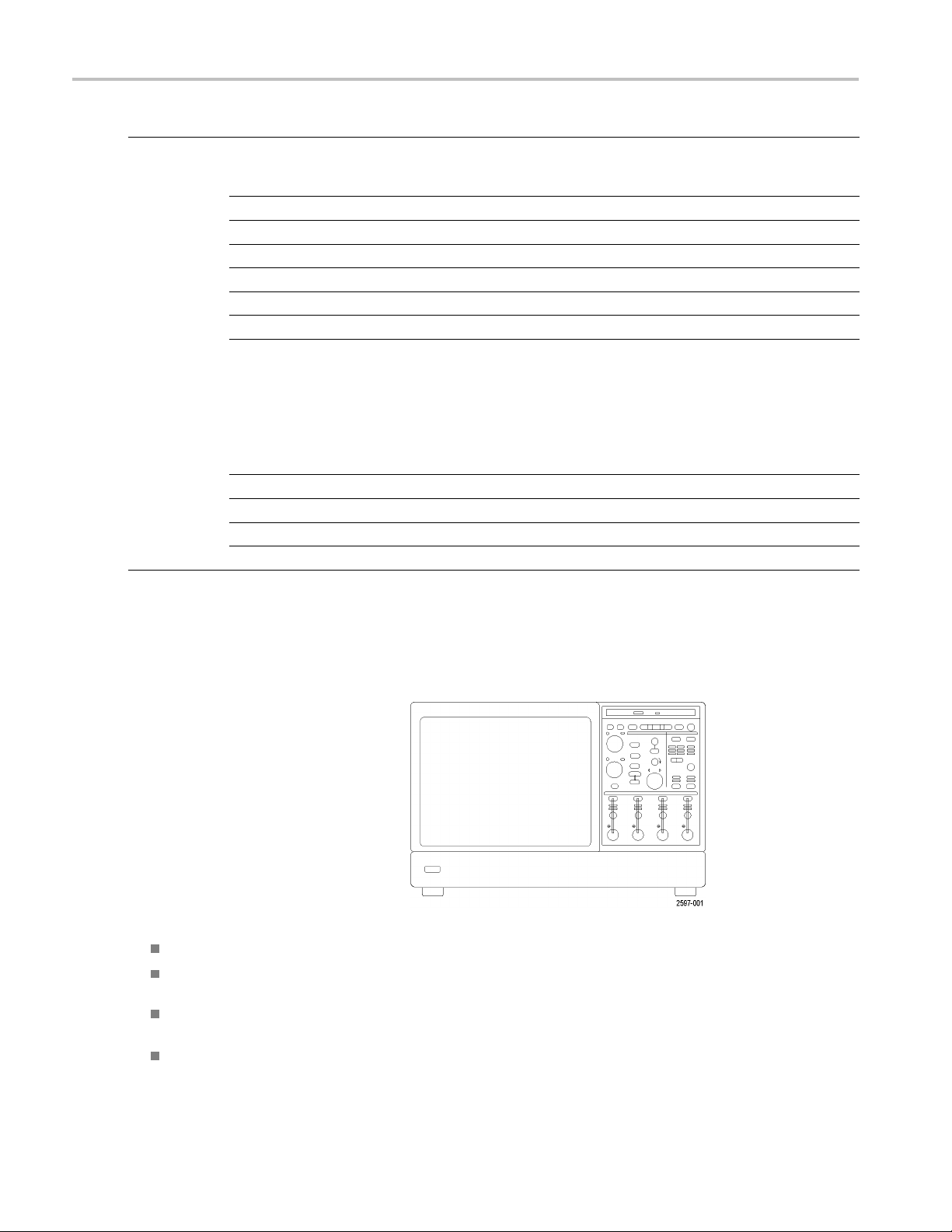
MSO5000 and DPO5000 Series
1. Front panel controls
2. Ground terminal
3. Probe compensation output
4. Auxiliary Triggerinput
5. Channel 1–4 inputs
6. Logic probe input
7. USB ports
Side and Rear Panels
MSO70000/C, DSA70000B/C, and DPO70000B/C
MSO5000 and DPO5000 Series
Getting Acquain
tedwithYourInstrument
1. Removable hard disk drive
2. PS-2 connector for mouse
3. USB host ports
4. Passive eSATAPort
5. RJ-45 LAN connector to connect to
network
6. TekLinkconnector
7. GPIB port to connect to controller
8. Line Out connector for speaker
NOTE. S o me instruments may have
additional audio connectors.
9. Mic connector for microphone
10. DVI-I Video port
11. COM 1 and COM 2 serial ports
12. PS-2 connector for keyboard
13. Auxiliary output
MSO70000/C, DSA70000B/C, and DPO70000B/C Series
14. Reference output
15. External reference input
MSO70000/C, DPO/DSA70000B/C, DPO7000, and MSO/DPO5000 Series User Manual 17
Page 39

Getting Acquain
DSA70000B and, DPO70000B
1. Removable hard disk drive
2. PS-2 connector for mouse
3. USB host ports
4. Centronics Parallel Port
5. RJ-45 LAN connector to connect to
network
ted with Your Instrument
6. Video port to
7. TekLink con
8. GPIB port to
NOTE. Some instruments may have
additional audio connectors.
9. Line In connector
10. Line Out connector for speaker
11. Mic connector for microphone
12. Video port to connect a monitor
13. COM 1 serial port
14. PS-2 connector for keyboard
15. CTR Bass speaker
16. Side speaker out
17. Rear speaker out
18. Auxiliary output
19. Reference output
connect a monitor
nector
connect to controller
DSA70000B a
nd DPO70000B Series
20. External reference input
18 MSO70000/C, DPO/DSA70000B/C, DPO7000, and MSO /DP O5000 Series U ser Manual
Page 40

DPO7000
1. USB host ports
Getting Acquain
tedwithYourInstrument
2. Video port to c
NOTE. S o me instruments may have
additional audio connectors.
3. Mic connector for microphone
4. Line Out connector for speaker
5. Oscilloscope Only XGA Out video port to
connect a monitor
6. Printer c onnection
7. Line In connector
8. RJ-45 LAN connector to connect to
network
9. Centroni
10. COM 1 seri
11. PS-2 con
12. PS-2 con
13. Rear spe
onnect a monitor
cs Parallel Port
al port
nector for mouse
nector for keyboard
aker out
14. Side sp
15. CTR Bas
16. Remova
17. GPIB p
18. Auxil
19. Chann
20. Exter
iary output
el 3 output
nal reference input
eaker out
s speaker
ble hard disk drive
ort to connect to controller
DPO
7000 Series
MSO70000/C, DPO/DSA70000B/C, DPO7000, and MSO/DPO5000 Series User Manual 19
Page 41

Getting Acquain
MSO5000 and DPO5000
1. Line In connector
2. Line Out connector for speaker
3. Mic connector for microphone
4. Video port to connect a monitor
5. PS-2 connector for keyboard
6. PS-2 connector for mouse
7. USB host ports
8. RJ-45 LAN connector to connect to
network
9. USBDeviceport
10. Probe Power input, use 119-7465-xx
power supply
11. External reference input
ted with Your Instrument
12. Auxiliary output
13. Security lock input
14. AC Power input
15. Removable hard disk drive cover
16. Ground connection
MSO5000 and DPO5000 Series
20 MSO70000/C, DPO/DSA70000B/C, DPO7000, and MSO /DP O5000 Series U ser Manual
Page 42

Getting Acquain
To use PS-2 devices, they must be plugged in before you power on the instrument. PS-2 devices must not be hot swapped.
tedwithYourInstrument
Interface and
The menu bar mode provides access to commands that control all of the instrument features and functions. The toolbar mode
provides acc
1. Menu Bar: Access to data I/O, printing,
online help,
2. Buttons/Me
toolbar and menu bar modes and to
customize your toolbar
3. Multipurpose Knob Readouts: Adjust
and displa
multipurpose knobs
4. Display: Live, reference, math, digital,
and bus waveforms display here, with
cursors
5. Waveform
change vertical position of a waveform
or bus. Click the handle and change the
nandscale usingthe multipurpose
positio
knobs.
6. Controls Status: Quick reference to
vertical selections, scale, offset, and
parame
Display
ess to the most common features.
and instrument functions
nu: Click to toggle between
y parameters c ontrolled by the
Handle: Click and drag to
ters
7. Readou
WARNING. If there is vertical clipping, there may be a dangerous voltage on the probe tip, but the readout will indicate a low
age. A
volt
measurements where the signal is vertically clipped produce inaccurate results. Clipping also causes inaccurate amplitude
values in waveforms that are stored or exported for use in other programs. If a math waveform is clipped, it will not affect
ampl
8. Sta
ts: Display cursor and
measurement readouts in this area.
Measurements are selectable from the
menu ba
is displayed, some combinations of
readouts move to the graticule area.
to record length and horizontal parameters
r or toolbar. If a control window
symbol appears in the measurement readout if a vertical clipping condition exists. Automatic amplitude-related
itude measurements on that math waveform.
tus: Display of acquisition status, mode, and number of acquisitions; trigger status; date; time; and quick reference
MSO70000/C, DPO/DSA70000B/C, DPO7000, and MSO/DPO5000 Series User Manual 21
Page 43

Getting Acquain
1. Buttons/Menu: Click to toggle between
toolbar and menu bar modes and to
customize the
ted with Your Instrument
toolbar
2. Drag cursors t
screen
3. Drag the position icons to reposition a
waveform
4. Click the icon to assign the multipurpose
knobs to wave
scale
5. Drag across the waveform area to create
a box for zooming, enabling/disabling
histograms
6. Drag icon t
o measure waveforms on
form vertical position and
, and gating measurements
o change the trigger level
22 MSO70000/C, DPO/DSA70000B/C, DPO7000, and MSO /DP O5000 Series U ser Manual
Page 44

Control Panel
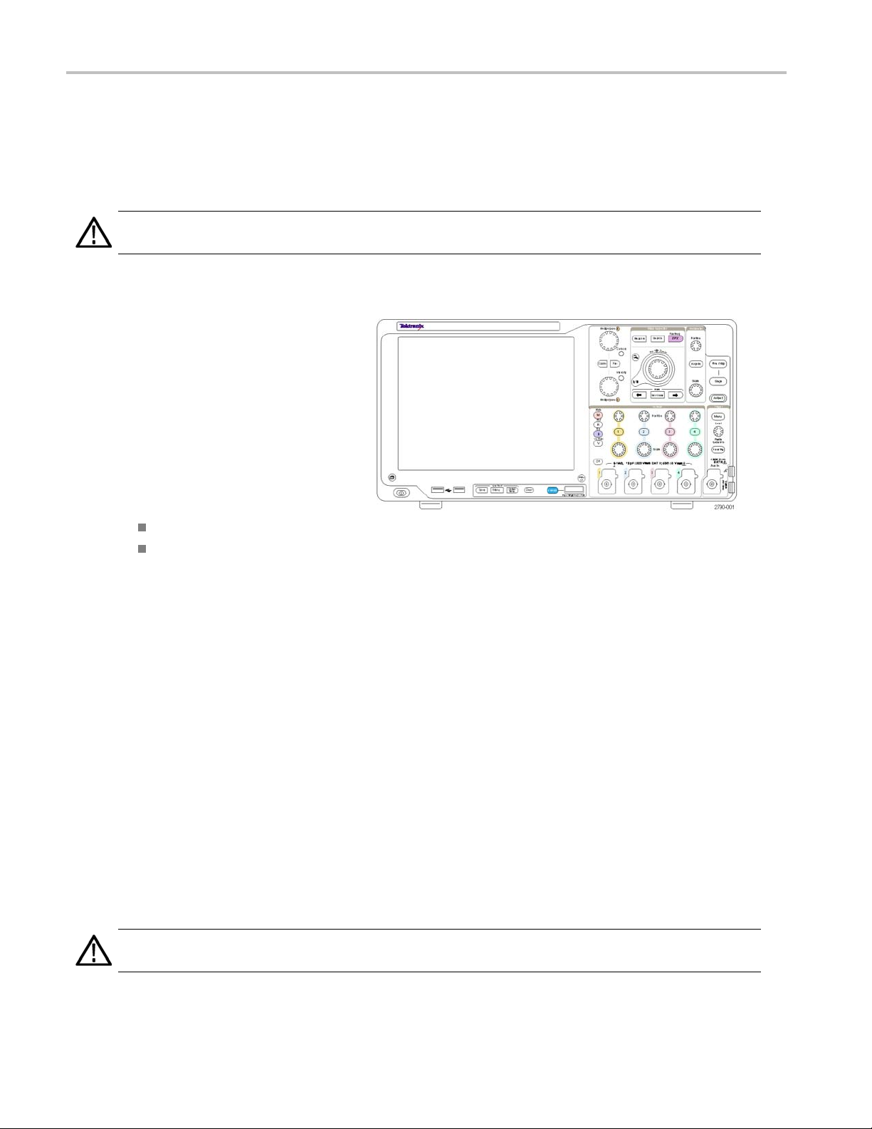
MSO70000/C, DSA70000B/C, DPO70000B/C, an d DPO7000
1. Push to automatically set up the vertical,
horizontal, and trigger controls based on
selected channels.
2. Push to return settings to default values.
3. Push to make a hard copy or save a
screen capture.
4. Push to turn on MultiView Zoom and add
a magnified graticule to the display.
5. Horizontally scale, position, delay, and
set record length (resolution) of all
waveforms.
6. Use to start and stop acquisition, start a
single acquisition sequence, clear data,
or start fast acquisitions.
7. Use to set the trigger parameters. Push
Advanced to display additional trigger
functions. T he Arm, Ready, and Trig’D
lights show the acquisition status.
Getting Acquain
tedwithYourInstrument
8. Turn to adjust waveform intensity.
9. Turn to adjust parameters selected from
the screen interface. Push to toggle
between normal and fine adjustment.
10. Push to turn cursors on or off.
11. Use to search and mark waveforms.
12. Push to turn the touch screen on and off.
13. Turn channel displays on and off.
Vertically scale, position, or offset the
waveform. Toggle between position and
offset.
On MSO70000 Series instruments, turn
on digital channels using the Digital
> Digital Setup menu. (See page 48,
Setting Up Digital Signal Input.)
MSO70000/C, DPO/DSA70000B/C, DPO7000, and MSO/DPO5000 Series User Manual 23
Page 45

Getting Acquain
MSO5000 and DPO5000
ted with Your Instrument
1. Turn to adjust
the screen interface. Push Fine to select
fine adjustment, push Course to select
course adjust
2. Push to turn c
3. Push to adjus
a Multipurpose knob.
4. Push to turn on MultiView Zoom and add
a magnified graticule to the display.
5. Push to perform automated
measureme
an acquisition for user-defined
events/criteria, or start or stop fast
acquisiti
6. Horizonta
horizontal and acquisition parameters of
all waveforms.
7. Turn the inner zoom knob to control the
zoom fact
to scroll the zoom window through the
acquiredwaveform. Pushthe play-pause
button t
panning of a waveform. Control the
speed and direction with the pan knob.
parameters selected from
ment.
ursors on or off.
t waveform intensity using
nts, search through
ons.
lly scale, position, and set the
or. Turn the outer pan knob
o start or stop the automatic
8. Use to start and stop acquisition or start
e acquisition sequence.
a singl
9. Use to s
establish or delete a waveform m ark, or
to jump to the previous or next waveform
mark.
10. Pusht
horizontal, and trigger controls based on
selected channels.
earch and mark waveforms, to
o automatically set up the vertical,
24 MSO70000/C, DPO/DSA70000B/C, DPO7000, and MSO /DP O5000 Series U ser Manual
Page 46

Getting Acquain
tedwithYourInstrument
11. Usetosetthetr
Push Menu to display additional trigger
functions.
12. Turn channel displays on and off.
Verticallysc
OnMSO5000Series instruments,turn on
digital channels by pushing the D15–D0
button or usi
menu. (See page 48, Setting Up Digital
Signal Input.)
13. Push to turn the touch screen on and off.
14. Pushto display the math, reference, bus,
or vertica
15. Push to tur
16. Push to ac
(MSO5000 Series only).
17. Push to clear data.
18. Push to return settings to default values.
19. Push to save and recall setups,
waveforms, and screen images.
igger parameters.
ale or position the waveform.
ng the Digital > Digital Setup
l setup menus.
n off a displayed menu.
cess the digital setup menu
20. Push to make a hard copy or save a
capture.
screen
Accessing Online Help
In-depth information is available in the online help on all the features of your instrument.
To access context-sensitive help on the
active window, select Help > Help on
Window... or press F1.
MSO70000/C, DPO/DSA70000B/C, DPO7000, and MSO/DPO5000 Series User Manual 25
Page 47

Getting Acquain
ted with Your Instrument
1. Toaccess any to
select Help > Contents and Index....
2. Use the Contents, Index, Search, or
Favorites tab to select the topic, and
then click Dis
To navigate within the help system:
Click a button in a help window to
navigate between the Overview and
specificto
Click the M
window to move help out of the way so
you can operate the instrument.
Click Alt and Tab to see the last help
topic aga
pic in the help system,
play.
pics.
inimize button in the help
in.
Accessing Menus and Control Windows
Access menus and control windows using the following techniques:
Click a menu, and then select a
command.
26 MSO70000/C, DPO/DSA70000B/C, DPO7000, and MSO /DP O5000 Series U ser Manual
Page 48

Getting Acquain
tedwithYourInstrument
Forashortcut m
enu,right-clickanywhere
in the graticule or on an object. The
shortcut menu is context sensitive and
varies with th
e area or object where you
right-clicked. Some examples a re shown
in the figure at right.
In the toolbar mode, click a button to
quickly access a setup control window.
(See page 21.)
MSO70000/C, DPO/DSA70000B/C, DPO7000, and MSO/DPO5000 Series User Manual 27
Page 49

Inspect Your Ins
trument
Inspect Your Instrument
Use the following procedures to verify the functionality of your instrument.
Verify Internal Diagnostics Pass
1. Power o n the instrument.
2. Select Instrument Diagnostics....
3. Click Ru
diagnostics control window.
4. Verify that all tests pass. If diagnostic
failures occur, contact your local
Tektro
n. The test results appear in the
nix service personnel.
28 MSO70000/C, DPO/DSA70000B/C, DPO7000, and MSO /DP O5000 Series U ser Manual
Page 50

Acquisition
This section contains concepts of and procedures for using the acquisition system.
Signal Path Compensation
Use this procedure if the temperature has changed more than 5 °C (9 °F) since the last signal path compensation (SPC).
Perform the s
Tektronix considers it a best practice to run SPC when using the instrument to measure signals with higher sensitivity
(10 mV/div and lower) settings regardless of temperature shift or time since it was last run. Failureto do so may result in
the instrum
1. Prerequisites: instrument powered on for 20 minutes,
and all input signals removed.
2. Select Instrument Calibration.
ignal path compensation regularly to ensure that your measurements have the highest level of accuracy.
ent not meeting warranted performance levels.
Acquisition
3. When the Temperature Status changes
dy, click Run SPC to start the
to Rea
calibration. Calibrationmay take 10 to
15 minutes.
MSO70000/C, DPO/DSA70000B/C, DPO7000, and MSO/DPO5000 Series User Manual 29
Page 51

Acquisition
2. Select Instrument Calibration.
4. If the instrument does not pass,
recalibrate the instrument, or have the
instrume
nt serviced by qualified service
personnel.
NOTE. To always show the SPC status icon
or displa
y a warning when SPC has not
been run in more than a month, click the
corresponding check box.
5. If the SPC needed icon is red, perform a
signal path compensation.
30 MSO70000/C, DPO/DSA70000B/C, DPO7000, and MSO /DP O5000 Series U ser Manual
Page 52

Setting Up Analog Signal Input
Use front-panel buttons to set up y our instrument to acquire the signal.
1. Connect the probe to the input signal source.
CAUTION. To prevent damage to the instrument, always wear an antistatic wrist strap when making connections to the
instrument and observe the maximum input voltage ratings for input connectors.
MSO70000/C, DSA70000B/C, and DPO70000B/C Series DPO7000 Series
Acquisition
MSO5000 and DPO5000 Series
2. Select the input channel by pushing the front-panel buttons to toggle the channels on and off.
MSO5000 and DPO5000 Series
MSO70000/C, DSA70000B/C, DPO 70000B/C, and DPO7000
Series
MSO70000/C, DPO/DSA70000B/C, DPO7000, and MSO/DPO5000 Series User Manual 31
Page 53

Acquisition
3. Push Autoset.
4. Adjust the ver
MSO5000 a
tical position, scale, and offset using the front-panel knobs.
nd DPO5000 Series
MSO70000/C, DSA70000B/C, DPO70000B/C, and DPO7000
Series
5. Adjust the horizontal position and scale using the front-panel knobs.
The horiz
ontal position determines the number of pretrigger and posttrigger samples.
00 and DPO5000 Series
MSO50
MSO70000/C, DSA70000B/C, DPO70000B/C, and DPO7000
Series
32 MSO70000/C, DPO/DSA70000B/C, DPO7000, and MSO /DP O5000 Series U ser Manual
Page 54

Using Default Setup
Acquisition
1. Toquickly ret
DEFAULT SETUP.
urn to the factory default settings, push
MSO70000/C,
Series
MSO5000 and DPO5000 Series
DSA70000B/C, DPO70000B/C, and DPO7000
MSO70000/C, DPO/DSA70000B/C, DPO7000, and MSO/DPO5000 Series User Manual 33
Page 55

Acquisition
Using Autoset
Use Autoset to quickly and automatically set up the instrument (acquisition, horizontal, trigger, and vertical) based on the
characteristics of the input signal. Autosetmakes adjustments to the signal such that the waveform displays two or three
cycles with the trigger level near the m idlevel.
1. Connect the probe, and then select the
input channel. (See page 31, Setting Up
Analog Signal Input.)
2. Push the AUTOSET button to execute
an Autoset.
MSO70000/C, DSA70000B/C, DPO70000B/C, and DPO7000 Series
MSO5000 and DPO5000 Series
3. Click Undo to undo the last Autoset.
Parameters that are not affected by
Autoset retain their settings.
Quick Tips
Autoset automatically sets up the analog channels.
On instruments with iCapture, autoset automatically sets up the iCapture channels.
To position the waveform appropriately, Autoset may c hange the verticalposition. Autoset may also adjust vertical offset.
If you use Autoset when one or more channels are displayed, the instrument selects the lowest numbered channel for
horizontal scaling and triggering. You can individually control the vertical scaling of each c hannel.
34 MSO70000/C, DPO/DSA70000B/C, DPO7000, and MSO /DP O5000 Series U ser Manual
Page 56

Acquisition
If you use Autoset when no channels are displayed, the instrument turns on channel one (Ch 1) and scales it.
Close Autoset Undo control window by clicking the X. After Autoset Undo closes, you can still undo the last Autoset by
selecting the
Undo Last Autoset command from the Edit menu.
Stopthe Autos
etUndo control window from opening automatically by changing the User Preferences in theUtilities menu.
Probe Compensation, Calibration, and Deskew
To optimize measurement accuracy,see the instrument online help to perform the following procedures:
Compensate passive probes
Calibrate active probes
Deskew input channels
Acquisition Concepts
Acquisition Hardware
Before a signal is displayed, it must pass through the input channel where it is scaled and digitized. Eachchannel has a
dedicated input amplifier and digitizer. Each channel produces a stream of digital data from which the instrument extracts
waveform records.
Sampling Process
Acquisition is the process of sampling an
analog signal, converting it into digital data,
and assembling it into a waveform record,
which is then stored in acquisition memory.
Real-Time Sampling
Inreal-time sampling,the instrument digitizes
all of the points it acquires using one trigger
event. Use real-time sampling to capture
single-shot or transient events.
MSO70000/C, DPO/DSA70000B/C, DPO7000, and MSO/DPO5000 Series User Manual 35
Page 57

Acquisition
Interpolated Real-Time Sampling
In interpolated real-time sampling, the
instrument di
acquires using one trigger event. If the
instrument cannot acquire enough samples
for a com plete
real-time sample r ate, it interpolates. Use
interpolated real-time s ampling to capture
single-shot
gitizes all of the points it
waveform at the maximum
or transient events.
Equivalent-Time Sampling
The instrument uses equivalent-time
sampling to extend its sample rate beyond
ime maximum sampling rate.
its real-t
Equivalent-time sampling is only used if
Equivalent Time is selected and the time
base is set
to create a waveform record using real-time
sampling.
The instr
of a repetitive waveform to obtain the sample
density required for one complete waveform
record.
should only be used with repetitive signals.
to a sampling rate that is too fast
ument makes multiple acquisitions
Thus, equivalent time sampling
36 MSO70000/C, DPO/DSA70000B/C, DPO7000, and MSO /DP O5000 Series U ser Manual
Page 58

Waveform Record
Acquisition
The instrumen
through use of the following parameters:
Sample interval: The time between
sample points.
Record length: The number of samples
required to fi
Triggerpoin
a waveform record.
Horizontal position: When horizontal
delay is off, the horizontal position is
a percenta
between 0 and 99.9 percent. The trigger
point and the horizontal reference are at
thesameti
For example, if the horizontal position is
50 percent, then the trigger point is in the
middle of
horizontal delay is on, the time from the
trigger point to the horizontal reference
is the hor
t builds the waveform record
ll a waveform record.
t: The zero time reference in
ge of the waveform record
me in the waveform record.
the waveform record. When
izontal delay.
Interpolation
Yourinstrument can interpolate between the samples it acquires when itdoes not have all of the actual samples it needs to fill
thewaveform record. Linear interpolation computes recordpoints between actual acquired samples by using astraight line fit.
Sin(x)/x interpolation computes record points using a curve fit between the actual values acquired. Sin(x)/x interpolation
is the default interpolation mode because it requires fewer actual sample points than linear interpolation to accurately
represent the waveform.
MSO70000/C, DPO/DSA70000B/C, DPO7000, and MSO/DPO5000 Series User Manual 37
Page 59

Acquisition
How the Acquisition Modes Work
Sample mode retains the first sampled point
from each acquisition interval. Sample is the
default mode.
Peak Detect mode uses the highest and
lowest of all the samples contained in two
consecutive
only works with real-time, noninterpolated
sampling and is useful for catching high
frequency gl
Hi Res mode calculates the average
of all the sa
interval. Hi-Res provides a higher-resolution,
lower-bandwidth waveform.
Envelope mode finds the highest and
lowest record points over many acquisitions.
Envelope uses Peak Detect for each
individual acquisition.
Average mode calculates the average value
for each record point over many acquisitions.
Average uses Sample mode for each
individual acquisition. Use average mode to
reduce random noise.
Waveform Database mode is a
three-dimensional accumulation of source
waveform data over several acquisitions. In
addition to amplitude and timing information,
the database includes a count of the number
of times a specific waveform point (time and
amplitude) was acquired.
acquisition intervals. This mode
itches.
mples for each acquisition
38 MSO70000/C, DPO/DSA70000B/C, DPO7000, and MSO /DP O5000 Series U ser Manual
Page 60

Changing the Acquisition Mode
Use this procedure to change the acquisition mode.
1. Select Horiz/Acq > Acquisition Mode.
2. Toselect an acquisition mode, do one
of the following:
Select an acquisition mode directly
from the menu.
Click Mode..., and then select an
acquisition mode.
Acquisition
3. For Aver
modes, click the #ofWfmscontrol, and
then set the number of waveforms with
the mul
mode, click the Samples control, and
then set the number of samples with the
multi
age or Envelope acquisition
tipurpose knob. For WfmDB
purpose knob.
Quick Tip
Click the keypad icon to set the number of waveforms or samples.
MSO70000/C, DPO/DSA70000B/C, DPO7000, and MSO/DPO5000 Series User Manual 39
Page 61

Acquisition
Starting and Stopping an Acquisition
After the channels that you want to acquire are selected, use the following procedure.
1. Push the front-panel RUN/STOP button
to start the acquisition.
2. Push the RUN/STOP button again to
stop the acquisition.
3. To take a single acquisition, push the
Single button.
MSO70000/C, DSA70000B/C, DPO70000B/C, and DPO7000 Series
MSO5000 and DPO5000 Series
Selecting the Horizontal Mode
Your instrument has three horizontal modes. Automatic is the default mode. Select the horizontal mode that works best
for your test setup.
To set the horizontal mode, select Horiz/Acq
> Horizontal/Acquisition Setup to display
the horizontal control window. Chooseone
of the modes described below.
InAutomatic modeyou can set the Scaleand
Sample Rate. Record length is a dependent
variable. If changing the scale would cause
the record length to exceed the Record
Length Limit, the sample rate is decreased
to the next available setting.
If the sampling mode is real time and
the sample rate is at the real time limit,
attempting to increase the sample rate has
no effect.
40 MSO70000/C, DPO/DSA70000B/C, DPO7000, and MSO /DP O5000 Series U ser Manual
Page 62

Acquisition
To set the Recor
Length Limit and set the limit using the
buttons or keypad. The default maximum
limit depends
record length option.
In Constant Sample Rate mode you can
set the Sam
default sample rate ensures bandwidth filter
operation. Record length is a dependent
. The maximum record length
variable
depends on your instrument model and
record length option.
The front
sample rate in both automatic and constant
sample rate modes.
d Length Limit, click Record
on your instrument model and
ple Rate and Scale. The
-panel resolution knob changes the
MSO70000/C, DPO/DSA70000B/C, DPO7000, and MSO/DPO5000 Series User Manual 41
Page 63

Acquisition
In Manual mode you can set the Sample
Rate and Record Length. Horizontal Scale
is a dependent
sample rate and record length. Masks are
not supported in manual mode.
The Horizont
length in manual mode.
All three modes interact with sample rate,
scale, and record length as shown. The
horizontal line is the maximum real-time
sample rate. Eachstaircase shows that as
you increase the scale, the sample rate must
decrease when either the maximum record
length or the record length limit you set is
reached. Manual mode uses the maximum
record length.
Automatic and Constant Sample Rate
modes are identical. However, Constant
Sample Rate mode keeps the sample r ate
constant at a rate that guarantees bandwidth
enhancement filters are used.
variable calculated from the
al Scale knob changes record
Quick Tips
Digital sample rate and resolution are dependent variables, and are controlled by the analog sample rate selection.
42 MSO70000/C, DPO/DSA70000B/C, DPO7000, and MSO /DP O5000 Series U ser Manual
Page 64

Using FastAcq
Fast acquisition mode reduces the dead time between waveform acquisitions, enabling the capture and display of transient
events such as glitches or runt pulses. Fast acquisition mode can also display waveform phenomena at an intensity that
reflects their rate-of-occurrence.
Use the following procedure:
1. Push FastAcq.
Acquisition
MSO70000/C, DSA70000B/C, DPO70000B/C, and DPO7000 Series
2. Find glitches, transients, orother random
events.
When you have identified an anomaly,
set the trigger system up to look for it.
(See page 159, Capturing Intermittent
Anomalies.)
MSO5000 and DPO5000 Series
MSO70000/C, DPO/DSA70000B/C, DPO7000, and MSO/DPO5000 Series User Manual 43
Page 65

Acquisition
Quick Tips
Digital channels and buses are not available in FastAcq mode.
To optimize for capturing details or rare events, select Horiz/Acq > Horizontal/Acquisition Setup > Acquisition> Fast
Acq, and then select Optimize For Capturing Details or Capturing rare events.
On MSO5000 and DPO5000 Series instruments, Fast Acq mode is not available in XY or X YZ Display modes.
44 MSO70000/C, DPO/DSA70000B/C, DPO7000, and MSO /DP O5000 Series U ser Manual
Page 66

Using DSP Enhanced Bandwidth
If your instrument has the enhanced bandwidth feature, use the DSP (digital signal processing) enhanced bandwidth for
more accurate rise time measurements, to extend the bandwidth, and flatten the passband at the full sample rate. The
enhanced bandwidth provides a matched response across enabled channels so you can perform channel-to-channel
comparison and differential measurements.
1. Push AUTOSET to set the horizontal,
vertical, and trigger controls or set the
controls manually.
Acquisition
MSO70000/C, DSA70000B/C, DPO70000B/C, and DPO7000 Series
2. Select Vertical > Bandw idth
Enhanced....
MSO5000 and DPO5000 Series
MSO70000/C, DPO/DSA70000B/C, DPO7000, and MSO/DPO5000 Series User Manual 45
Page 67

Acquisition
3. Click Digital Filters (DSP) Enabled to
turn the enhanced bandwidth on. You
must set the sa
enable DSP.
4. To force a constant sample rate that
enables DSP filters, check Force
Constant Sam
NOTE. If not already set, selecting Constant
Sample rate sets the horizontal mode to
constant sa
to allow DSP, and selects a DSP bandwidth.
5. Select the desired bandwidth from the
Bandwidth list.
The availa
depend on your instrument, probe, and
probe tip.
Selectin
hardware (HW) bandwidth.
6. Toapply your selections to all c hannels,
check Apply To A ll Channels.
When dif
impossible for the instrument to set all
channels the same, the instrument sets
each ch
value possible.
mple rate correctly to
ple Rate.
mple rate, sets the sample rate
ble bandwidth selections
g Analog Only selects a
ferent probing makes it
annel to the closest bandwidth
dwidth indicator appears in the
The ban
vertical readout when the enhanced
bandwidth is turned on.
Quick
Tips
Right click the waveform handle to display a menu where you can select the channel bandwidth and other bandwidth
enhanced settings.
The DSP enhanced bandwidth occurs at maximum sample rate.
Use the DSP enhanced bandwidth when your signals have rise times less than 50 ps.
Select Analog Only for higher waveform throughput, overdriven signals, and when you prefer to use your own DSP
post-processing.
You can limit the instrument bandwidth by selecting Vertical > Bandwidth Limit and then selecting the bandwidth.
46 MSO70000/C, DPO/DSA70000B/C, DPO7000, and MSO /DP O5000 Series U ser Manual
Page 68

Using Roll Mode
Roll mode gives a display similar to a strip chart recorder for low-frequency signals. Roll mode displays acquired data points
without waiting for the acquisition of a complete waveform record.
1. Select Ho riz/Acq >
Horizontal/Acquisition Setup....
2. If not selected, click the Acquisition tab.
Click Auto to turn on Roll mode.
Acquisition
NOTE. Roll
Detect, or Hi Res acquisition mode.
3. Tostop acquisitions in Roll mode:
mode requires Sample, Peak
If you are not in Single Sequence,
push RUN/STOP to stop Roll mode.
If you are in Single Sequence, Roll
mode acquisitions stop automatically
when a complete record is acquired.
MSO70000/C, DSA70000B/C, DPO70000B/C, and DPO7000 Series
MSO5000 and DPO5000 Series
Quick Tips
Switching to Envelope, Average, or WfmDB acquisition mode will turn off Roll mode.
Roll mode is disabled when you set the horizontal scale to 50 ms per division or faster.
MSO70000/C, DPO/DSA70000B/C, DPO7000, and MSO/DPO5000 Series User Manual 47
Page 69

Acquisition
Setting Up Digital Signal Input
Use D igital setup menus to set up the digital channels to acquire signals. Digital channels are available on MSO70000/C and
MSO5000 Series instruments only.
1. Connectthelogicprobetotheinstrument.
2. Connect the probe to the input signal
sources.
CAUTION. To prevent damage to the
instrument always wear an antistatic wrist
strap when making connections to the
instrument and observe the maximum input
voltage ratings for input connectors.
MSO70000/C, DSA70000B/C, and DPO70000B/C Series
3. Set up digital channels and buses using
the Digital menus.
(See page 48, Setting Up Digital Channels.)
and (See page 50, Setting Up a Bus.)
Setting Up Digital Channels
You can set a digital channel threshold, size, position and label on MSO70000/C and MSO5000 Series instruments.
1. Select Digital > Digital Setup.
MSO5000 and DPO5000 Series
48 MSO70000/C, DPO/DSA70000B/C, DPO7000, and MSO /DP O5000 Series U ser Manual
Page 70

2. Select the D7 - D0 or D15 - D8 tab for
the digital channels you want to set up.
3. Click a digital channel button to toggle
thedisplay of
thedigital channel on or off.
Acquisition
4. Click Thres
them using the keyboard or multipurpose
knobs. Or, set the threshold of all 16
channels b
value and clicking Apply.
5. Tochange the displayed vertical size of
all digit
the display size from the list.
6. Tochan
the label and enter a new label using the
keyboard.
hold or Position and adjust
y entering a Global Threshold
al channels, click Size and select
ge a digital channel label, click
MSO70000/C, DPO/DSA70000B/C, DPO7000, and MSO/DPO5000 Series User Manual 49
Page 71

Acquisition
Setting Up a Bus
You can set up serial and parallel buses on MSO70000/C, MSO5000, and DPO5000 Series instruments.
1. SelectVertical > Bus Setup or,on some
instruments, Digital > Bus Setup.
2. Select the Config tab.
50 MSO70000/C, DPO/DSA70000B/C, DPO7000, and MSO /DP O5000 Series U ser Manual
Page 72

3. Scroll to, and then select the bus to set
up.
4. Totoggle the display of the bus on or off,
click the Bus b
5. Tochange the default label of the bus,
click Label and enter a new label using
the keyboard.
6. Tochange the displayed position of the
bus, click Bus Position and use the
keyboard or multipurpose knob to enter
a new bus position.
utton.
Acquisition
7. To select
Serial or Parallel.
You can set up each bus type.
(See pag
page 53, Set Up a Parallel Bus.)
the bus type, click Bus Type
e 51, Set Up a Serial Bus.) or (See
Quick Tips
Position a bus or waveform by clicking on the bus or waveform handle and dragging the handle to the desired position.
Set Up a Serial Bus
You can set serial bus parameters. Youcan use digital channels in bus definitions on MSO Series instruments only.
MSO70000/C, DPO/DSA70000B/C, DPO7000, and MSO/DPO5000 Series User Manual 51
Page 73

Acquisition
1. To set up a seria
Serial and select the type of serial bus
from the drop-down list.
Each bus type ha
parameters that you set up. Set up other
bus types as appropriate for the selected
bus.
See the online help for additional help setting
up a bus.
2. To select the input for the displayed
components of the bus, click the
component Input and select from the
displayed list.
3. To set an i
Threshold and enter the threshold using
the keypad.
l bus, select B us Type
s its own collection of
nput threshold, double click
NOTE. To
when they are currently shared, go to Trig >
A Event (Main) Trigger S etup and change
Setting
4. Toselect the polarity for the displayed
set thresholds independently
s to Independent.
components of the bus, click the
component Polarity and select from the
displayed list.
52 MSO70000/C, DPO/DSA70000B/C, DPO7000, and MSO /DP O5000 Series U ser Manual
Page 74

Set Up a Parallel Bus
You can set parallel bus parameters. Youcan use digital channels in bus definitions on MSO Series instruments only.
1. Toset up a parallel bus, select Bus Type
Parallel.
See the online help for additional help
setting up a bus.
2. Toadd sources to the bus, click the Add
Sources Select button.
3. Click the button for each channel you
want in the bus. The order of the parallel
bus is determined by the order in which
you select the channels. Digital channels
are available as sources only on MSO
Series instruments.
4. Click the OK button.
Acquisition
5. Tomove a channel within the bus, scroll
to and select the channel you want to
and then click the up or down
move,
arrow buttons.
6. To remove a channel within the bus,
scroll to and select the channel you want
ove, and then click the Remove
to rem
button.
7. To set channel thresholds, click the
Thresholds Setup button.
MSO70000/C, DPO/DSA70000B/C, DPO7000, and MSO/DPO5000 Series User Manual 53
Page 75

Acquisition
8. For each thresh
double click the channel Threshold, and
enter the threshold using the keypad or
multipurpose
9. When the desir
set, click the OK button.
10. To set all channels to the same threshold,
double click Global Threshold and use
the keypad to
click Apply.
11. On MSO70000/C instruments, to set the
clock source and polarity,double click the
item and sel
To set the clock level, double click the
Clock Level, and enter the level using the
keypad or m
old you want to set,
knobs.
ed thresholds have been
enter a threshold. Then
ect from the displayed list.
ultipurpose knobs.
Set Up Bus Display
You can set the bus style and decoding. You can use digital channels in bus definitions on MSO Series instruments only.
1. Select Digital > Bus Setup.
54 MSO70000/C, DPO/DSA70000B/C, DPO7000, and MSO /DP O5000 Series U ser Manual
Page 76

2. Select the Display tab.
3. To select the bus, scroll to display the
bus, and then select the bus.
4. To select the bus style and decoding,
click the des
buttons.
ired bus style and decoding
Acquisition
5. Ifusingasy
Symbol. Click Lookup Table and use
the keyboard to enter the full path to the
table file,
the symbol table file.
For some buses other settings are
available
appropriate for your bus.
See the online help for additional help
setting u
mbol table, check Use
or click Browse and browse to
. Set the other settings as
p a bus.
MSO70000/C, DPO/DSA70000B/C, DPO7000, and MSO/DPO5000 Series User Manual 55
Page 77

Acquisition
When and Why to Turn On MagniVu
For the MSO5000 Series, MagniVugives you higher resolution to accurately determine edge placement. Thishelps you
make precise timing measurements on digital edges. You can see up to 32 times more detail than with normal digital
channel sampling.
The MagniVu record is acquired in parallel to the main digital acquisition and is available at any time, running or stopped.
MagniVu provides an ultra high resolution view of your data sampled at a maximum resolution of 60.6 ps for 10,000 points
centered around the trigger.
NOTE. MagniVu centers itself around the trigger point. If you turn MagniVu on while using a large record length and you are
looking somewhere other than the trigger point, then the digital signal may be off screen. In most of these cases, you can find
the digital record by looking for the digital signal in the upper overview and panning accordingly.
Using MagniVu
1. Push D15 – D0.
2. SelectD
On.
igital > MagniVu to toggle MagniVu
Quick Tips
If you think you need more timing resolution, turn on MagniVuto increase the resolution.
MagniVu is always acquired. If the oscilloscope is in a stopped state, turn on MagniVu and still get the resolution
without taking another acquisition.
56 MSO70000/C, DPO/DSA70000B/C, DPO7000, and MSO /DP O5000 Series U ser Manual
Page 78

Viewing Analog Characteristics of Digital Waveforms
iCapture allows you to view the analog characteristics of digital channel signals. Additional measurement capabilities are
available while viewing the analog characteristics of a waveform. iCapture is available on MSO70000/C Series instruments.
1. Select Vertical > Vertical Setup.
Acquisition
2. Press the D
3. Click Di
channel to send through the analog
input.
igital Input iC apture button.
gital Source and select a digital
MSO70000/C, DPO/DSA70000B/C, DPO7000, and MSO/DPO5000 Series User Manual 57
Page 79

Acquisition
4. Toset channel t
converting an analog waveform to digital
format for inclusion in a bus, click the
Digital Prope
5. Tochoose whe
settings or have independent threshold
settings, click Channel Settings and
select Shar
list.
6. For each threshold you want to set, click
the channel threshold. Set the threshold
using the k
7. When the re
set, click the OK button.
hresholds used when
rties button.
ther to share threshold
ed or Independent from the
eypad or multipurpose knobs.
quired thresholds have been
58 MSO70000/C, DPO/DSA70000B/C, DPO7000, and MSO /DP O5000 Series U ser Manual
Page 80

Using FastFrame Mode
FastFrame allows you to capture many trigger events as single records in a larger record, and then view and measure
each record individually. Time Stamps display the absolute trigger time for a specific frame and the relative time between
triggers of two specified frames.
1. Push AUTOSET to set the horizontal,
vertical, and trigger controls or set the
controls manually.
Acquisition
2. Select Horiz/Acq > FastFrame Setup....
MSO70000/C
MSO5000 and DPO5000 Series
, DSA70000B/C, DPO70000B/C, and DPO7000 Series
MSO70000/C, DPO/DSA70000B/C, DPO7000, and MSO/DPO5000 Series User Manual 59
Page 81

Acquisition
3. Push FastFrame to toggle it On.
4. Select Frame Size and # of Events
Frames. Then use the multipurpose
knobs to set ea
frames represents the number of trigger
events that are captured. Framesize is
the number of
with each trigger event (or frame.) The
number of frames is reduced if there
is insuffici
records. Theshorter the frame length,
the more frames you can acquire.
5. Use the Frame Viewing controls to select
the frame that you want to view.
6. Toview multiple frames superimposed
over each other, select Overlay.
ch one. Number of
samples that are stored
ent memory to store all the
7. Use the Time Stamps controls to select
the source for,and frame number of, the
reference frame. The reference frame
is the starting point when measuring the
relative time between two frames.
Quick Tips
Digital channels and buses are not available in FastFrame mode.
Use FastFrame when you want to preserve the data associated with each trigger event for further analysis or visual
inspections.
60 MSO70000/C, DPO/DSA70000B/C, DPO7000, and MSO /DP O5000 Series U ser Manual
Page 82

Use FastFrame when you want to capture multiple events that have long dead times between them that are of no
interest to you
.
Acquisition
Multiple fram
may be hard to distinguish if you use Temp or Spectral.
es are best viewed with the Normal, Green, or Gray color palettes because the dark blue selected frame
Using FastFrame Frame Finder
Frame finder allows you to find a FastFrame frame that is different from other frames.
1. Select the source of the FastFrame
frames.
2. Set the Search Range by entering the
From Frame # and the To Frame #.
3. Push Run/
Stop to stop acquisitions.
MSO70000/C, DSA70000B/C, DPO70000B/C, and DPO7000 Series
MSO5000 and DPO5000 Series
MSO70000/C, DPO/DSA70000B/C, DPO7000, and MSO/DPO5000 Series User Manual 61
Page 83

Acquisition
4. Push Start to start the search.
Frame Finder searches for and displays a
different frame.
5. If the anomaly you are looking for is not
in the disp
layed frame, push No.Frame
Finder searches for another different
frame.
6. Iftheanomalyyouarelookingforisin
the displ
ayed frame, push Yes.
7. If you ar
e done searching, push Stop.
8. Push Run/Stop to restart acquisitions.
MSO70000/C, DSA70000B/C, DPO70000B/C, and DPO7000 Series
MSO5000 and DPO5000 Series
62 MSO70000/C, DPO/DSA70000B/C, DPO7000, and MSO /DP O5000 Series U ser Manual
Page 84

Using TekLink and MultiScope Trigger
To get more than 4 channels associated with a single trigger event, get more than 4 channels looking for a problem on a
channel, or build a big AND gate with more than 4 inputs, use TekLink.
NOTE. When using MultiScope Trigger, the B Triggers are not available. TekLink and MultiScope Trigger are not available
on DPO7000, MSO 5000, and DPO5000 Series instruments.
Link 2 Instruments
1. Connect two instrumentsusing a TekLink
cable.
Acquisition
2. TekLinkconnection status is displayed in
the horizontal readout.
3. Select Trig > A Event (Main) Trigger
Setup....
MSO70000/C, DPO/DSA70000B/C, DPO7000, and MSO/DPO5000 Series User Manual 63
Page 85

Acquisition
4. Select the MultiScope Triggertab.
5. Enable MultiScope Triggering by
selectingEnable MultiScope Triggering
(with TekLink
).
6. Select Sends
instrument to trigger both instruments in
the instrument-instrument setup. The
other instru
receive the trigger.
If not using a hub, all trigger types are
available o
trigger.
7. To calibrate the MultiScope Trigger,
press the Align button.
Trigger to enable the
ment is automatically set to
n the instrument supplying the
Link Multiple Instruments
Two or more instruments are connected using a TekLink Hub.
1. Connect two or more instruments using
a TekLinkhub and cables.
2. TekLinkconnection status is displayed in
the horizontal readout.
64 MSO70000/C, DPO/DSA70000B/C, DPO7000, and MSO /DP O5000 Series U ser Manual
Page 86

3. Select Trig > A Event (Main) Trigger
Setup....
Acquisition
4. Select the M
5. Enable Mult
selectingEnable MultiScope Triggering
(with TekLink).
6. Select Contribute to enable the
instrumen
TekLinksetup. The other instruments are
automatically set to receive the trigger.
7. Select AND or select OR to combine all
contributed triggers before triggering all
instruments in the TekLinksetup.
AND triggering with a hub works with
edge and pattern trigger types.
OR triggering with a hub works with all
trigger types.
8. To alig
the Align button.
ultiScope Trigger tab.
iScope Triggering by
t to supply a trigger in the
n the MultiScope Trigger,press
MSO70000/C, DPO/DSA70000B/C, DPO7000, and MSO/DPO5000 Series User Manual 65
Page 87

Acquisition
9. If you want the instrument to scan
the TekLink network to see which
instrumentsa
reconnected to the TekLink
network, press the Refresh button.
10. When MultiScope triggering is enabled,
it displays in the trigger readout.
66 MSO70000/C, DPO/DSA70000B/C, DPO7000, and MSO /DP O5000 Series U ser Manual
Page 88

Pinpoint Tr iggers
The Pinpoint trigger system comes with advanced trigger types that are usable on both A and B triggers, and it can reset the
trigger sequence if the B event does not occur after a specific number of events or a specific time. Pinpoint triggers support
capture of events based on the most complex trigger event or sequence of trigger events.
Only a portion of the Pinpoint trigger functionality is available on MSO5000 and DPO5000 instruments.
This section contains concepts and procedures for using the trigger system.
Triggering Concepts
Pinpoint Trigge
rs
Trigger Eve
The trigger event establishes the time-zero point in the waveform record. All waveform record data a re located in time with
respect to that point. The instrument continuously acquires and retains enough sample points to fill the pretrigger part of the
waveform record. When a trigger event occurs, the instrument starts acquiring samples to build the posttrigger part of the
waveform record (displayed after, or to the right of, the trigger event). Once a trigger is rec ognized, the instrument will not
accept another trigger until the acquisition is complete and the holdoff time has expired.
nt
Trigger M odes
The trigger mode determines how the instrument behaves in the absence of a trigger event:
Normal trigger mode enables the instrument to acquire a waveform only when it is triggered. If no trigger occurs, the last
waveform record acquired remains on the display. If no last waveform exists, no waveform is displayed.
Auto trigger mode enables the instrument to acquire a waveform even if a trigger does not occur. Auto mode uses a timer
arts after a trigger event occurs. If another trigger event is not detected before the timer times out, the instrument
that st
forces a trigger. The length of time it waits for a trigger event depends on the time base setting.
Auto mode, when forcing triggers in the absence of valid triggering events, does not synchronize the waveform on the
display. The waveform will appear to roll across the screen. Ifvalid triggers occur, the display will become stable.
In edge-trigger mode, force the instrument to trigger by pushing the Force Triggerbutton on the Trigger Setup control window.
Select the trigger mode in the Trig > Mode menu. For more information, see the instrument online help.
ger Holdoff
Trig
Trigger holdoff can help stabilize triggering, by extending the period in which further trigger recognition is suppressed after
initiating an acquisition. Such an extension can help the system skip over the remaining events of a recurring burst of events,
and thus always trigger on the first event in each burst. Adjust holdoff to obtain stable triggering when the instrument is
triggering on undesired trigger events.
Set the trigger holdoff in the Trig > Holdoff menu. For more information, see the instrument online help.
MSO70000/C, DPO/DSA70000B/C, DPO7000, and MSO/DPO5000 Series User Manual 67
Page 89

Pinpoint Trigge
Trigger Coupling
Trigger coupling determines what part of the signal is passed to the trigger circuit. Edge triggering can use all available
coupling types: AC, DC, Low Frequency Rejection, High Frequency Rejec tion, and Noise Rejection. All other trigger types
use DC coupling only. Your instrument may not offer all coupling types.
Select the trigger coupling in the Trig > A Event (Main) Trigger Setup menu. Formore information, see the instrument
online help.
Horizontal Position
Horizontal position defines where the trigger occurs on the waveform record. It lets you choose how much the instrument
acquires be
part that occurs after the trigger is the posttrigger part.
Pretrigger data is valuable when troubleshooting. For example, if you are trying to find the cause of an unwanted glitch
in your test circuit, trigger on the glitch and make the pretrigger period large enough to capture data before the glitch.
By analyzi
Alternatively,to see what is happening in your system as a result of the trigger event, make the posttrigger period large
enough to capture data after the trigger.
rs
fore and after the trigger event. The part of the record that occurs before the trigger is the pretrigger part. The
ng what happens before the glitch, you may uncover information that helps you find the source of the glitch.
Slope an
The slope control determines whether the instrument finds the trigger point on the rising or the falling edge of a signal. The
level control determines where on that edge the trigger point occurs.
d Level
Delayed Trigger System
You can trigger with the A (Main) trigger system alone or combine the A (Main) trigger with the B (Delayed) trigger to
trigger on sequential events. When using sequential triggering, the A trigger event arms the trigger system, and the B
er event triggers the instrument when the B trigger conditions are met. Aand B triggers can (and typically do) have
trigg
separate sources. The B trigger condition is based on a time delay or a specified number of events. (See page 74, Using A
(Main) and B (Delayed) Triggers.)
68 MSO70000/C, DPO/DSA70000B/C, DPO7000, and MSO /DP O5000 Series U ser Manual
Page 90

Choosing a Trigger Type
Pinpoint Trigge
rs
Your instrume
the Trigger Setup control window.
NOTE. Some trigger type selections are not available on some instruments.
1. Select Trig > Edge Setup.
2. Set the so
mode using the setup m enu.
nt allows you to modify basic trigger parameters from the front panel or set up more advanced triggers in
urce, slope, coupling, and
MSO70000/C, DPO/DSA70000B/C, DPO7000, and MSO/DPO5000 Series User Manual 69
Page 91

Pinpoint Trigge
3. Toselect one of the other trigger types,
rs
select a trigger type directly from the Trig
menu.
4. Complete the trigger setup using the
controls displayed for the trigger type.
ntrols to set up the trigger vary
The co
dependingon the trigger type, instrument
model, and options.
70 MSO70000/C, DPO/DSA70000B/C, DPO7000, and MSO /DP O5000 Series U ser Manual
Page 92

Trigger Selections
Trigger Type Trigger Conditions
Edge
Glitch
Width
Runt
Window
Timeout
Pinpoint Trigge
Triggeron a rising or falling edge, as defined by the slope control. Coupling choices
are DC, AC, LF Reject, HF Reject, and Noise Reject.
Trigger on a pulse narrower (or wider) than the specified width or ignore glitches
narrower (or wider) than the specified width.
Trigger on pulses that are inside or outside a specified time range. Can trigger
on positive or negative pulses.
Triggeron a pulse amplitude that crosses one threshold but fails to cross a second
threshold before recrossing the first. Can detect positive or negative runts, or only
those wider than a specified width. These pulses can also be qualified by the logical
state of other channels.
Trigger when the input signal rises above an upper threshold level or falls below a
lower threshold level. Trigger the instrument as the signal is entering or leaving the
threshold window. Qualify the trigger event in terms of time by using the Trigger
When Wider option, or by the logical state of other channels using the Trigger When
Logic option.
Trigger when no pulse is detected within a specified time.
rs
Transition
Serial Trigger on 64-bit serial pattern at data rates up to 1.25 Gb/s (<4 GHz models) and
Pattern
State Trigger when all of the logic inputs to the selected logic function cause the function to
Setup/ Hold
Comm Triggerwith mask testing on communications codes and standards (analog channels
Bus
Video
Triggeron pulse edges that traverse between two thresholds at faster or slower rates
than the specified time. The pulse edges can be positive or negative.
1 to 4 8b10b symbols at data rates up to 3.125 Gb/s (≥4 GHz models only) or
6.25 Gb/s (≥4 GHz B models). Lock on a pseudo-random bit sequence. Requires
Option PTM or PTH. This m ode includes clock recovery. Push the Push to Set
50% knob to reinitialize clock recovery.
Pattern Lock automatically finds and locks on a long repeating pseudo-random
bit sequence (PRBS). This lock means that the instrument knows the bit length of
the pseudo-random bit sequence and can predict when the cycle repeats. Pattern
Lock enables the instrument to take samples at specific locations in a data pattern
with outstanding time base accuracy.
Triggerwhen logic inputs cause the selected function to become True or False. You
can also specify that the l ogic conditions must be satisfied for a specificamountof
time before triggering.
be True or False when the clock input changes state.
Triggerwhen a logic input changes state inside the setup and hold times relative to
the clock. The mode triggers on a setup and hold violation.
only). Thecontrols work together to define the parameters for the trigger event
(availablewithOptionMTMorMTHonsomeinstruments). This mode includes clock
recovery. Push the Push to Set 50% knob to reinitialize clock recovery.
Trigger on components (such as a specified address) of a bus that you define.
With some instruments and options, trigger types include parallel, SPI, RS-232,
USB, and I
Triggeron specified fields or lines of a composite video signal (DPO7000, MSO5000,
and DPO5000 Series only). Only composite signal formats are supported.
2
C triggers.
MSO70000/C, DPO/DSA70000B/C, DPO7000, and MSO/DPO5000 Series User Manual 71
Page 93

Pinpoint Trigge
rs
Trigger Type Trigger Condit
CAN Trigger on CAN
ions
Bus signals.
RS-232 Trigger on RS-232 signals (DPO7000 Series only).
I2C Trigger on In
ter-IC Control (I2C) signals: start, stop, repeated start, missing
acknowledge, address, data, and address and data.
SPI Trigger on Serial Peripheral Interface (SPI) signals.
72 MSO70000/C, DPO/DSA70000B/C, DPO7000, and MSO /DP O5000 Series U ser Manual
Page 94

Checking Trigger Status
Check the trigger status from the status lights o n the front panel or from the readout.
Check the ARM, READY, and TRIG’D
front-panel controls to determine the trigger
status.
If TRIG’D is on, the instrument has
recognized a valid trigger and is filling
the posttrigger part of the waveform.
If READY is on, the instrument can
accept, and is waiting for, a valid trigger
to occur. Pretrigger data has been
acquired.
Pinpoint Trigge
rs
If ARM is on, the trigger circuitry is
filling the pretrigger part of the waveform
record.
If both TRIG’D and READY are on,
a valid A event trigger has been
recognized and the instrument is waiting
for a delayed trigger. When a delayed
trigger is recognized, the posttrigger part
of the delayed waveform will fill.
If ARM, TRIG’D, and READY are off,
acquisitions have stopped.
To quickly determine the settings of some
key trigger parameters, check the Trigger
readout at the bottom of the display. The
readouts differ for edge and the advanced
triggers:
1. A trigger source = Ch1
2. Trigger slope = rising edge
3. Trigger level
MSO70000/
C, DSA70000B/C, DPO70000B/C, and DPO 7000 Series
4. Time base
5. Check the ARM, READY,and TRIG’D
readout to determine the trigger status.
6. Check the Auto/Normal readout to
determine the trigger mode.
MSO70000/C, DPO/DSA70000B/C, DPO7000, and MSO/DPO5000 Series User Manual 73
Page 95

Pinpoint Trigge
rs
Using A (Main) and B (Delayed) Triggers
You can use the A Event (Main) trigger for simple signals or combine it with the B Event (Delayed) trigger to capture
more complex signals. After the A Event occurs, the trigger system looks for the B Event before triggering and displaying
the waveform.
A Trigger
1. Select Trig > A Event (Main) Trigger
Setup....
2. Set the A trigger type and source in the
A Event tab.
B Trigger (Delayed)
NOTE. B triggers are not available if
MultiScope Trigger is enabled.
3. Choose a function in the A →B Seq tab.
4. Set the trigger delay time or the number
of B events.
74 MSO70000/C, DPO/DSA70000B/C, DPO7000, and MSO /DP O5000 Series U ser Manual
Page 96

5. Set the B trigger characteristics in the B
Event (Delayed) tab.
6. Select Normal Trigger Mode and Auto
Holdoff in the Mode tab.
Pinpoint Trigge
rs
Trigger on B Event
The A trigger arms the instrument.
Posttrigger acquisition starts on the nth B
event.
MSO70000/C, DPO/DSA70000B/C, DPO7000, and MSO/DPO5000 Series User Manual 75
Page 97

Pinpoint Trigge
B Trigger After Delay Time
The A trigger arms the instrument.
Posttrigger a
edge after the trigger delay time.
rs
cquisition starts on the first B
Triggering
You can specify a condition to reset the
trigger system if it occurs before the B trigger
event. Whe
trigger system stops waiting for the B event
and returns to waiting for the A event.
Triggeri
MSO5000 and DPO5000 instruments.
with Reset
n the reset event occurs, the
ng with reset is not available on
Quick Tips
ger delay time and horizontal delay time are independent functions. When you establish a trigger condition using
B-trig
either the A trigger alone or the A and B triggers together, you can also use horizontal delay to delay the acquisition
by an additional amount.
cting Trigger Position
Corre
Triggerposition correction c orrects for differences in the data path and the trigger path to more accurately place the trigger
on the displayed waveform. Trigger position correction can also use averaging to more accurately place the trigger on noisy
signals. Tomore accurately place edge triggers on the display, perform the following procedure.
76 MSO70000/C, DPO/DSA70000B/C, DPO7000, and MSO /DP O5000 Series U ser Manual
Page 98

Pinpoint Trigge
rs
1. To more accurat
on the display, check Enhanced
Triggering. To more accurately place
the trigger on n
Optimized for Noisy S ign als .
The O ptimized for Noisy Signals
selection is o
Triggering is selected.
ely place the trigger
oisy signals, also check
nly available if Enhanced
Triggering with B-Event Scan
Use A->B Sequence B-Event Scan to create overlapped eye diagrams synchronized or initiated by an A trigger event.
Trig on nth Event captures the nth B-Event that occurs after the A-Event for all acquisitions. B-Event Scan automatically
advances the B-Event value to capture different portions of the signal.
1. Set the A trigger type and source in the
A Event tab.
2. Set the
MSO70000/C, DPO/DSA70000B/C, DPO7000, and MSO/DPO5000 Series User Manual 77
B trigger type and source in the
B Event tab.
Page 99

Pinpoint Trigge
rs
3. To more accu rat
on the display, check Enhanced
Triggering. Tomore accurately place
the trigger on
Optimized for Noisy Signals.
4. Select Tri
Scan in the A>B Seq tab.
5. To display the B Event Scan Setup
window,press B Event Scan > Setup.
ely place the trigger
noisy signals, also check
g on nth Event and B Event
6. Set the B
7. Set the
8. Set the
the B Event value is incremented.
Event start value.
B Event ending value.
number of acquisitions before
78 MSO70000/C, DPO/DSA70000B/C, DPO7000, and MSO /DP O5000 Series U ser Manual
Page 100

9. Select the method that the B Event value
is incremented after the selected number
of acquisitio
ns occur:
Sequential Scan increments by
1 until the End Event is reached.
When the End E
B Event value is reset to the Start
Event value and the process starts
over.
Random Scan sets the B Event
value to a random value between
the Start Ev
for each set of Advance After
acquisitions.
Toggle Bet
the B Event value between the Start
Event and the End Event for each
set of Adva
vent is reached, the
ent and the End Event
ween Events toggles
nce After acquisitions.
Pinpoint Trigge
rs
10. In this ex
on Ch 1 and the DQ signal is on Ch 2.
The instrument is in Run Mode with
Display
The instrument trigger setup was as
follows:
ample, a DDR3 DQS signal is
Mode set to Infinite Persistence.
t Window trigger on Ch 1
A-Even
to detect the DDR3 DQS Write
condition.
t Edge trigger on Either slope
B-Even
on Ch 1 to trigger on the DQS (clock)
edges.
equence set to Trig on the
A->B S
nth Event.
B Scan Enabled with Start Event
d Event = 8, and Mode =
=1,En
Sequential.
The data eyes are formed by the DQ
al on Ch 2.
sign
MSO70000/C, DPO/DSA70000B/C, DPO7000, and MSO/DPO5000 Series User Manual 79
 Loading...