


6 Series B Mixed Signal Oscilloscopes
Specifications and Performance Verification
(MSO64B, MSO66B, MSO68B)
Warning: The servicing instructions are for use by qualified personnel only. To avoid personal injury, do not perform any servicing unless you are qualified
to do so. Refer to all safety summaries prior to performing service.
Supports Product Firmware V1.28 and above
Register now!
Click the following link to protect your product.
www.tek.com/register
*P 077169503*
077-1695-03

Copyright © Tektronix. All rights reserved. Licensed software products are owned by Tektronix or its subsidiaries or suppliers, and are
protected by national copyright laws and international treaty provisions. Tektronix products are covered by U.S. and foreign patents, issued
and pending. Information in this publication supersedes that in all previously published material. Specifications and price change privileges
reserved.
TEKTRONIX and TEK are registered trademarks of Tektronix, Inc.
Tektronix, Inc.
14150 SW Karl Braun Drive
P.O. Box 500
Beaverton, OR 97077
USA
For product information, sales, service, and technical support:
• In North America, call 1-800-833-9200.
• Worldwide, visit www.tek.com to find contacts in your area.

Table of Contents
Table of Contents
List of Figures................................................................................................................................................................................5
List of Tables................................................................................................................................................................................. 6
Important safety information..........................................................................................................................................................7
General safety summary........................................................................................................................................................7
To avoid fire or personal injury........................................................................................................................................7
Probes and test leads..................................................................................................................................................... 8
Service safety summary.........................................................................................................................................................8
Terms in the manual....................................................................................................................................................... 9
Terms on the product............................................................................................................................................................. 9
Symbols on the product......................................................................................................................................................... 9
Specifications.............................................................................................................................................................................. 10
Analog inputs....................................................................................................................................................................... 10
Timebase system.................................................................................................................................................................24
Trigger system..................................................................................................................................................................... 29
Analysis................................................................................................................................................................................35
Arbitrary function generator................................................................................................................................................. 36
Digital volt meter (DVM).......................................................................................................................................................38
Processor system................................................................................................................................................................ 38
Input/Output port specifications........................................................................................................................................... 40
Display system.....................................................................................................................................................................42
Data storage specifications..................................................................................................................................................43
Power supply system........................................................................................................................................................... 45
Safety characteristics...........................................................................................................................................................45
Environmental specifications............................................................................................................................................... 45
Dynamics............................................................................................................................................................................. 45
Comparison against MIL-PRF-28800F Environmental Requirements.................................................................................46
Mechanical specifications.................................................................................................................................................... 48
Environmental Compliance.................................................................................................................................................. 48
Regional Certifications, Classifications, and Standards List................................................................................................ 49
Performance verification procedures.......................................................................................................................................... 50
Test records......................................................................................................................................................................... 51
Instrument information, self test record.........................................................................................................................51
DC Offset Accuracy test record.................................................................................................................................... 52
Analog Bandwidth test record.......................................................................................................................................56
Input impedance test record......................................................................................................................................... 60
DC Gain Accuracy test record...................................................................................................................................... 60
Random Noise, sample acquisition mode test record...................................................................................................64
Random Noise, High Res mode test record............................................................................................................... 120
Long term sample rate through AFG DC offset accuracy test records....................................................................... 226
Performance tests..............................................................................................................................................................239
Prerequisites...................................................................................................................................................................... 239
Self test.............................................................................................................................................................................. 239
Check input impedance..................................................................................................................................................... 240
Check DC gain accuracy................................................................................................................................................... 241
6 Series B Mixed Signal Oscilloscopes Specifications and Performance Verification 3

Table of Contents
Check DC offset accuracy..................................................................................................................................................243
Check analog bandwidth....................................................................................................................................................244
Check random noise, sample acquisition mode (10, 8, and 6 GHz options)..................................................................... 245
Check random noise, High Res mode............................................................................................................................... 247
Check long term samples rate and delay time accuracy....................................................................................................248
Check digital threshold accuracy....................................................................................................................................... 249
Check AUX Out output voltage levels................................................................................................................................250
Check DVM voltage accuracy (DC)................................................................................................................................... 251
Check DVM voltage accuracy (AC)................................................................................................................................... 252
Check trigger frequency accuracy and maximum input frequency.................................................................................... 253
Arbitrary function generator............................................................................................................................................... 254
Check AFG sine and ramp frequency accuracy......................................................................................................... 254
Check AFG square and pulse frequency accuracy.....................................................................................................255
Check AFG signal amplitude accuracy.......................................................................................................................256
Check AFG DC offset accuracy..................................................................................................................................257
Index......................................................................................................................................................................................... 259
6 Series B Mixed Signal Oscilloscopes Specifications and Performance Verification 4

List of Figures
List of Figures
Figure 1: Frequency/period test................................................................................................................................................ 254
Figure 2: Frequency/period test................................................................................................................................................ 255
Figure 3: 50 Ω terminator accuracy...........................................................................................................................................256
Figure 4: Amplitude test............................................................................................................................................................ 256
Figure 5: 50 Ω terminator accuracy...........................................................................................................................................257
Figure 6: DC offset tests............................................................................................................................................................258
6 Series B Mixed Signal Oscilloscopes Specifications and Performance Verification 5

List of Tables
List of Tables
Table 1: Gain expected worksheet............................................................................................................................................241
Table 2: CF (Calibration Factor) = 1.414 × ((50 / Measurement Ω) + 1)...................................................................................256
Table 3: CF (Calibration Factor) = 0.5 × (( 50 / Measurement Ω) + 1)......................................................................................257
6 Series B Mixed Signal Oscilloscopes Specifications and Performance Verification 6

Important safety information
Important safety information
This manual contains information and warnings that must be followed by the user for safe operation and to keep the product in a safe
condition.
To safely perform service on this product, see the Service safety summary that follows the General safety summary.
General safety summary
Use the product only as specified. Review the following safety precautions to avoid injury and prevent damage to this product or any
products connected to it. Carefully read all instructions. Retain these instructions for future reference.
This product shall be used in accordance with local and national codes.
For correct and safe operation of the product, it is essential that you follow generally accepted safety procedures in addition to the safety
precautions specified in this manual.
The product is designed to be used by trained personnel only.
Only qualified personnel who are aware of the hazards involved should remove the cover for repair, maintenance, or adjustment.
Before use, always check the product with a known source to be sure it is operating correctly.
This product is not intended for detection of hazardous voltages.
Use personal protective equipment to prevent shock and arc blast injury where hazardous live conductors are exposed.
To avoid fire or personal injury
Use proper power cord Use only the power cord specified for this product and certified for the country of use.
Ground the product This product is grounded through the grounding conductor of the power cord. To avoid
electric shock, the grounding conductor must be connected to earth ground. Before making
connections to the input or output terminals of the product, ensure that the product is properly
grounded. Do not disable the power cord grounding connection.
Power disconnect The power cord disconnects the product from the power source. See instructions for the
location. Do not position the equipment so that it is difficult to operate the power cord; it must
remain accessible to the user at all times to allow for quick disconnection if needed.
Connect and disconnect properly Do not connect or disconnect probes or test leads while they are connected to a voltage
source.
Use only insulated voltage probes, test leads, and adapters supplied with the product, or
indicated by Tektronix to be suitable for the product.
Observe all terminal ratings To avoid fire or shock hazard, observe all rating and markings on the product. Consult the
product manual for further ratings information before making connections to the product. Do
not exceed the Measurement Category (CAT) rating and voltage or current rating of the lowest
rated individual component of a product, probe, or accessory. Use caution when using 1:1 test
leads because the probe tip voltage is directly transmitted to the product.
Do not apply a potential to any terminal, including the common terminal, that exceeds the
maximum rating of that terminal.
Do not operate without covers Do not operate this product with covers or panels removed, or with the case open. Hazardous
voltage exposure is possible.
Avoid exposed circuitry Do not touch exposed connections and components when power is present.
Do not operate with suspected
failures
If you suspect that there is damage to this product, have it inspected by qualified service
personnel.
6 Series B Mixed Signal Oscilloscopes Specifications and Performance Verification 7

Important safety information
Disable the product if it is damaged. Do not use the product if it is damaged or operates
incorrectly. If in doubt about safety of the product, turn it off and disconnect the power cord.
Clearly mark the product to prevent its further operation.
Before use, inspect voltage probes, test leads, and accessories for mechanical damage and
replace when damaged. Do not use probes or test leads if they are damaged, if there is
exposed metal, or if a wear indicator shows.
Examine the exterior of the product before you use it. Look for cracks or missing pieces.
Use only specified replacement parts.
Do not operate in wet/damp
conditions
Do not operate in an explosive
atmosphere
Keep product surfaces clean and dry Remove the input signals before you clean the product.
Provide proper ventilation Refer to the installation instructions in the manual for details on installing the product so it has
Provide a safe working environment Always place the product in a location convenient for viewing the display and indicators.
Be aware that condensation may occur if a unit is moved from a cold to a warm environment.
proper ventilation.
Slots and openings are provided for ventilation and should never be covered or otherwise
obstructed. Do not push objects into any of the openings.
Avoid improper or prolonged use of keyboards, pointers, and button pads. Improper or
prolonged keyboard or pointer use may result in serious injury.
Be sure your work area meets applicable ergonomic standards. Consult with an ergonomics
professional to avoid stress injuries.
Use care when lifting and carrying the product. This product is provided with a handle or
handles for lifting and carrying.
Use only the Tektronix rackmount hardware specified for this product.
Probes and test leads
Before connecting probes or test leads, connect the power cord from the power connector to a properly grounded power outlet.
Keep fingers behind the protective barrier, protective finger guard, or tactile indicator on the probes. Remove all probes, test leads and
accessories that are not in use.
Use only correct Measurement Category (CAT), voltage, temperature, altitude, and amperage rated probes, test leads, and adapters for
any measurement.
Service safety summary
The Service safety summary section contains additional information required to safely perform service on the product. Only qualified
personnel should perform service procedures. Read this Service safety summary and the General safety summary before performing any
service procedures.
To avoid electric shock Do not touch exposed connections.
Do not service alone Do not perform internal service or adjustments of this product unless another person capable of
rendering first aid and resuscitation is present.
Disconnect power To avoid electric shock, switch off the product power and disconnect the power cord from the
mains power before removing any covers or panels, or opening the case for servicing.
6 Series B Mixed Signal Oscilloscopes Specifications and Performance Verification 8
Important safety information
Use care when servicing with poweronDangerous voltages or currents may exist in this product. Disconnect power, remove battery
(if applicable), and disconnect test leads before removing protective panels, soldering, or
replacing components.
Verify safety after repair Always recheck ground continuity and mains dielectric strength after performing a repair.
Terms in the manual
These terms may appear in this manual:
Warning: Warning statements identify conditions or practices that could result in injury or loss of life.
CAUTION: Caution statements identify conditions or practices that could result in damage to this product or other property.
Terms on the product
These terms may appear on the product:
• DANGER indicates an injury hazard immediately accessible as you read the marking.
• WARNING indicates an injury hazard not immediately accessible as you read the marking.
• CAUTION indicates a hazard to property including the product.
Symbols on the product
When this symbol is marked on the product, be sure to consult the manual to find out the nature of the potential hazards and
any actions which have to be taken to avoid them. (This symbol may also be used to refer the user to ratings in the manual.)
The following symbols(s) may appear on the product.
6 Series B Mixed Signal Oscilloscopes Specifications and Performance Verification 9

Specifications
Specifications
This chapter contains specifications for the instrument. All specifications are guaranteed unless noted as "typical." Typical specifications
are provided for your convenience but are not guaranteed. Specifications that are marked with the ✓ symbol are checked in this manual.
All specifications apply to all models unless noted otherwise.
To meet specifications, these conditions must first be met:
• The instrument must have been calibrated in an ambient temperature between 18 °C and 28 °C (64 °F and 82 °F).
• The instrument must be operating within the environmental limits. (See Environmental specifications on page 45)
• The instrument must be powered from a source that meets the specifications. (See Power supply system on page 45)
• The instrument must have been operating continuously for at least 20 minutes within the specified operating temperature range.
• You must perform the Signal Path Compensation procedure after the warmup period. See the online help for instructions on how to
perform signal path compensation. If the ambient temperature changes more than 5 °C (9 °F), repeat the procedure.
Analog inputs
Number of analog input channels MSO64B: 4
MSO66B: 6
MSO68B: 8
Input coupling DC, AC
Input resistance selection 1 MΩ or 50 Ω
250 KΩ selectable for Performance Verification
✓DC Input Resistance, 50 Ω, DC
coupled
✓DC Input Resistance, 1MΩ DCCoupled
Input VSWR, 50 Ω DC-coupled, typical
Maximum input voltage, 50 Ω 2.3 V
Maximum input voltage 1 MΩ DCcoupled
50 Ω ±3%
1 MΩ ±1%
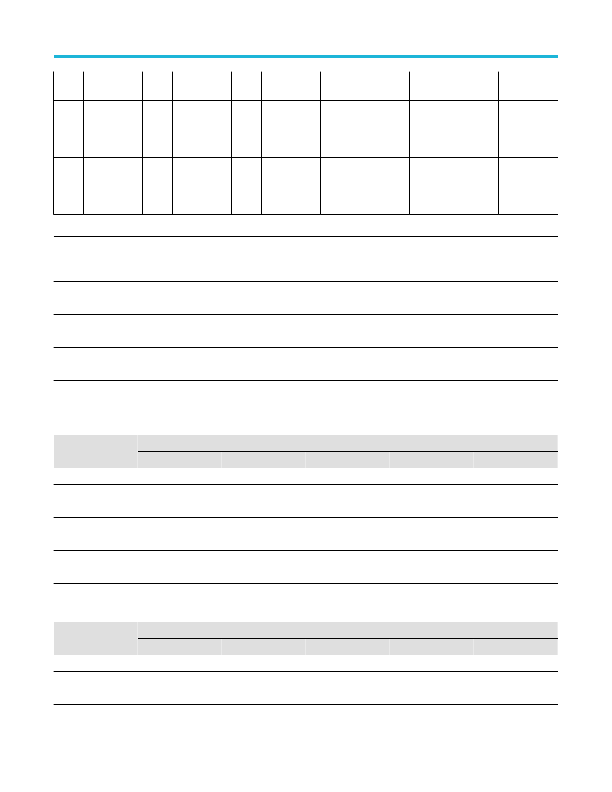
Input Frequency
≤2.5 GHz 1.4 1.2
>2.5 GHz and ≤6 GHz 1.5 1.3
>6 GHz and ≤9.5 GHz 1.9 1.8
>9.5 GHz and ≤10 GHz 2.1 1.9
, at <100 mV/div, with peaks ≤±20 V (Pulse Width ≤ 1 μs)
RMS
5.5 V
300 V
Maximum peak input voltage at the BNC, ±425 V
, at ≥ 100 mV/div, with peaks ≤±20 V (Pulse Width ≤ 200 μs)
RMS
, DC to 10 kHz
RMS
VSWR <100 mV/div
VSWR ≥ 100 mV/div
Sensitivity range, coarse
1 MΩ 500 µV/div to 10 V/div in a 1-2-5 sequence
50 Ω 1 mV/div to 1 V/div in a 1-2-5 sequence
6 Series B Mixed Signal Oscilloscopes Specifications and Performance Verification 10

Sensitivity range (Fine)
1 MΩ Allows continuous adjustment from 500µV/div to 10V/div
50 Ω Allows continuous adjustment from 1mV/divto 1V/div
Sensitivity Resolution (Fine) ≤1% of coarse sensitivity range setting
Specifications
Input capacitance 1 MΩ DC coupled,
typical
14.5 pF ±1.5 pF
Analog DC
Maximum offset ranges, Input signal cannot exceed maximum input voltage for the 50 Ω input path.
Volts/div Setting Maximum offset range, 50 Ω Input
1 mV/div - 99 mV/div ±1 V
100 mV/div - 1 V/div ±10 V
Volts/div Setting Maximum offset range, 1 MΩ Input
500 µV/div - 63 mV/div ±1 V
DC voltage measurement accuracy,
Average acquisition mode
64 mV/div - 999 mV/div
1 V/div - 10 V/div ±100 V
Input Signal cannot exceed max input voltage for the 50 Ω input path.
Measurement Type DC Accuracy (In Volts)
Average of ≥16 waveforms
±10 V
±((DC Gain Accuracy) * |reading - (offset position)| + Offset Accuracy + 0.05 * V/div
setting)
Delta volts between any two averages of
≥16 waveforms acquired with the same
oscilloscope setup and ambient conditions
DC voltage measurement accuracy,
Sample acquisition mode, typical
✓Offset accuracy
6 Series B Mixed Signal Oscilloscopes Specifications and Performance Verification 11
Measurement Type DC Accuracy (In Volts)
Any Sample ±(DC Gain Accuracy * |reading - (offset -
Delta volts between any two samples
acquired with the same scope setup and
ambient conditions
±(DC Gain Accuracy * |reading| + 0.1 div)
position)| + Offset Accuracy + 0.15 div + 0.6
mV)
±(DC Gain Accuracy * |reading| + 0.15 div
+1.2 mV)
50 Ω DC-coupled ≥5 mV/div: ± (0.005 X |offset – position| + 0.087 div)
2 mV/div: ± (0.005 X |offset – position| + 0.13 div)
1 mV/div: ± (0.005 X |offset – position| + 0.224 div)
1 MΩ DC-coupled ≥5 mV/div: ± (0.005 X |offset – position| + 0.2 div)
2 mV/div: ± (0.005 X |offset – position| + 0.237 div)
1 mV/div: ± (0.005 X |offset – position| + 0.384 div)
Offset and position in units of Volts
Position range ±5 divisions
✓DC gain accuracy
Specifications
50 Ω
±2.0%1 at >2 mV/div (±2.0% at 2 mV/div, ±4.0% at 1 mV/div, typical)
±1.0%2 of full scale at >2 mV/div, (±1.0% of full scale at 2 mV/div, ± 2.0% at 1 mV/div, typical)
1 MΩ
±2.0%1 at >2 mV/div (±2.0% at 2 mV/div, ±2.5% at 1 mV/div and 500 μV/div, typical)
±1.0%2 of full scale at >2 mV/div, (±1.0% of full scale at 2 mV/div, ±1.25% at 1 mV/div and 500
μV/div, typical)
✓Digital nonlinearity, typical INL @ > 2 mV/div: ±16 DL's (12-bit reference)
INL @ ≤ 2 mV/div: ±20 DL's (12-bit reference)
DNL: ±1.0 DL's (12-bit digitizing scale) when oscilloscope is in Hi-Res mode.
Analog AC
✓Analog bandwidth 50 Ω DC coupled
Model Volts/div Setting Bandwidth
MSO6XB BW-10000 1 mV/div – 1V/div DC - 10GHz
MSO6XB BW-8000 1 mV/div – 1V/div DC – 8 GHz
MSO6XB BW-6000 1 mV/div – 1V/div DC – 6 GHz
MSO6XB BW-4000 1 mV/div – 1V/div DC – 4 GHz
MSO6XB BW-2500 1 mV/div – 1V/div DC – 2.5 GHz
MSO6XB BW-1000 1 mV/div – 1V/div DC – 1 GHz
✓Analog Bandwidth, 1 MΩ
The limits are for ambient temperature of ≤30 °C and the bandwidth selection set to FULL.
Reduce the upper bandwidth frequency by 1% for each °C above 30 °C.
MSO6XB, all models:
Volts/Div Setting Bandwidth
1 mV/div – 10 V/div DC – 500 MHz
500 µV/div – 995 µV/div DC – 250 MHz
1
Immediately following SPC, add 2% for every 5 °C change in ambient.
2
Immediately following SPC, add 1% for every 5 °C change in ambient.
6 Series B Mixed Signal Oscilloscopes Specifications and Performance Verification 12

Specifications
Analog bandwidth TPP1000 10X
probe
The limits are for ambient temperature of ≤30 °C and the bandwidth selection set to FULL.
Reduce the upper bandwidth frequency by 1% for each °C above 30 °C.
Model Volts/Div Setting Bandwidth
MSO6X, all models 5 mV/div - 100 V/div DC - 1 GHz
Bandwidth selections
10 GHz model, 50 Ohm: 20 MHz, 200 MHz, 250 MHz, 350 MHz, 500 MHz, 1 GHz, 2 GHz, 2.5 GHz, 3 GHz, 4 GHz, 5 GHz,
6 GHz, 7 GHz, 8GHz, 9GHz, and 10 GHz.
8 GHz model, 50 Ohm 20 MHz, 200 MHz, 250 MHz, 350 MHz, 500 MHz, 1 GHz, 2 GHz, 2.5 GHz, 3 GHz,4 GHz, 5 GHz, 6
GHz, 7 GHz, and 8 GHz.
6 GHz model, 50 Ohm 20 MHz, 200 MHz, 250 MHz, 350 MHz, 500 MHz, 1 GHz, 2 GHz, 2.5 GHz, 3 GHz,4 GHz, 5 GHz,
and 6 GHz
4 GHz model, 50 Ohm 20 MHz, 200 MHz, 250 MHz, 350 MHz, 500 MHz, 1 GHz, 2 GHz, 2.5 GHz, 3 GHz, and 4 GHz
2.5 GHz model, 50 Ohm 20 MHz, 200 MHz, 250 MHz, 350 MHz, 500 MHz, 1 GHz, 2 GHz, and 2.5 GHz
1 GHz model, 50 Ohm 20 MHz, 200 MHz, 250 MHz, 350 MHz, 500 MHz, and 1 GHz
1M Ohm 20 MHz (HW), 200 MHz, 250 MHz (HW), 350 MHz, and Full (500 MHz)
Frequency response tolerance/
flatness, 50 Ω
± 0.5 dB from DC to 80% of rated bandwidth up to 8 GHz instruments
± 0.5 dB from DC To 65% of rated bandwidth for 10 GHz instruments
Combined TDP7700 and 6 Series B
MSO flatness, typical
±0.6 dB from DC to 80% of nominal BW when used with P77C292MM (SMA Probe Tip)
Not valid while using peak detect or envelope mode. Valid for probe modes A, B, and D
Phase accuracy ±2.5 degrees, typical out to 9 GHz
Lower frequency limit, AC coupled,
typical
<10 Hz when AC 1 MΩ coupled. The AC coupled lower frequency limits are reduced by a factor
of 10 (<1 Hz) when 10X passive probes are used.
Upper frequency limit, 250 MHz bandwidth limited, typical
50 Ω, DC-coupled 250 MHz, ± 5%
1 MΩ, DC-coupled 250 MHz, ± 25%
Upper frequency limit, 20 MHz bandwidth limited, typical
50 Ω, DC-coupled 20 MHz, ± 5%
1 MΩ, DC-coupled 20 MHz, ± 25%
Calculated rise time The formula used is 0.4/BW where BW is the measured –3 dB bandwidth of the oscilloscope.
The formula accounts for the rise time contribution of the oscilloscope independent of the rise
time of the signal source.
Calculated Rise Time (10% to 90%)
3
3
Below specification is independent of oscilloscope model and is dependent on bandwidth option only.
6 Series B Mixed Signal Oscilloscopes Specifications and Performance Verification 13
Effective bits (ENOB), typical
These limits apply to:
• Fastacq turned OFF
• 8 channel box: ch1, ch5
• 6 channel box: ch1, ch4
• 4 channel box: ch1, ch3
Specifications
Model 50 Ω TPP1000 Probe
1 mV-1 V 5 mV-10 V
MSO6X BW-10000 40 ps 400 ps
MSO6X BW-8000 50 ps 400 ps
MSO6X BW-6000 66.67 ps 400 ps
MSO6X BW-4000 100 ps 400 ps
MSO6X BW-2500 160 ps 400 ps
MSO6X BW-1000 400 ps 400 ps
50 mV/div, 50 GS, Sample mode, 50 ohm,
TYP
Channel bandwidth
Frequ
ency10GHz
10
MHz
250
MHz
1 GHz 6.6 6.75 6.85 7 7.1 7.3 7.45 7.7 7.8 7.95 8.3
2 GHz 6.55 6.65 6.75 6.85 7 7.2 7.35 7.55 7.65 7.75
4 GHz 6.45 6.65 6.75 6.95 7.05 7.2 7.35
7 GHz 6.55 6.65 6.75 6.9
2 mV/div, 50 GS, Sample mode, 50 ohm, TYP 2 mV/div, 25 GS, HiRes mode, 50 ohm, TYP
Frequ
ency10GHz
10
MHz
250
MHz
1 GHz 4.95 5.1 5.2 5.35 5.55 5.7 5.85 6.1 6.2 6.35 6.8
Table continued…
9 GHz 8 GHz 7 GHz 6 GHz 5 GHz 4 GHz 3 GHz 2.5
6.6 6.75 6.85 7 7.15 7.4 7.6 7.85 7.95 8.05 8.45 8.65 8.8 8.85 8.9 9.85
6.6 6.75 6.85 7 7.15 7.35 7.5 7.75 7.85 7.95 8.3 8.65 8.8 8.85
Channel bandwidth
9 GHz 8 GHz 7 GHz 6 GHz 5 GHz 4 GHz 3 GHz 2.5
4.95 5.1 5.2 5.35 5.55 5.7 5.9 6.1 6.2 6.35 6.8 7.25 7.5 7.65 7.85 9.25
4.95 5.1 5.2 5.35 5.55 5.7 5.85 6.1 6.2 6.35 6.8 7.25 7.5 7.65
50 mV/div, 25 GS, HiRes mode, 50 ohm, TYP
2 GHz 1 GHz 500
GHz
2 GHz 1 GHz 500
GHz
MHz
MHz
350
MHz
350
MHz
250
MHz
250
MHz
200
MHz20MHz
200
MHz20MHz
6 Series B Mixed Signal Oscilloscopes Specifications and Performance Verification 14
2 GHz 4.95 5.1 5.2 5.35 5.55 5.65 5.85 6.05 6.2 6.35
4 GHz 4.9 5.1 5.2 5.35 5.55 5.65 5.85
7 GHz 4.9 5.1 5.2 5.35
These limits apply to:
• 8 channel box: ch1, ch2, ch5, ch6
• 6 channel box: ch1, ch2, ch4, ch5
• 4 channel box: all channels
Specifications
50 mV/div, 25 GS, Sample mode, 50 ohm,
TYP
Channel bandwidth
Frequ
ency10GHz
10
MHz
250
MHz
1 GHz 6.25 6.4 6.5 6.6 6.8 7 7.15 7.4 7.5 7.65 8
2 GHz 6.2 6.3 6.4 6.6 6.7 6.95 7.1 7.35 7.4 7.5
4 GHz 6.2 6.3 6.4 6.5 6.7 6.95 7
7 GHz 6.2 6.2 6.3 6.4
2 mV/div, 25 GS, Sample mode, 50 ohm, TYP 2 mV/div, 12.5 GS, HiRes mode, 50 ohm, TYP
Frequ
ency10GHz
10
MHz
250
MHz
1 GHz 4.8 5 5.1 5.3 5.5 5.65 5.9 6.1 6.2 6.35 6.8
2 GHz 4.8 5 5.1 5.3 5.5 5.6 5.85 6.1 6.2 6.35
4 GHz 4.8 5 5.1 5.3 5.5 5.6 5.8
7 GHz 4.8 5 5.1 5.3
9 GHz 8 GHz 7 GHz 6 GHz 5 GHz 4 GHz 3 GHz 2.5
6.25 6.4 6.5 6.6 6.8 7.05 7.25 7.5 7.6 7.8 8.2 8.5 8.65 8.75 8.85 9.75
6.25 6.4 6.5 6.6 6.8 7 7.2 7.4 7.55 7.7 8.1 8.5 8.9 9
Channel bandwidth
9 GHz 8 GHz 7 GHz 6 GHz 5 GHz 4 GHz 3 GHz 2.5
4.8 5 5.1 5.3 5.5 5.65 5.9 6.1 6.2 6.35 6.8 7.2 7.4 7.5 7.75 8.8
4.8 5 5.1 5.3 5.5 5.65 5.9 6.1 6.2 6.35 6.8 7.2 7.4 7.5
50 mV/div, 12.5 GS, HiRes mode, 50 ohm, TYP
2 GHz 1 GHz 500
GHz
2 GHz 1 GHz 500
GHz
MHz
MHz
350
MHz
350
MHz
250
MHz
250
MHz
200
MHz20MHz
200
MHz20MHz
These limits apply to all channels
50 mV/div, 12.5 GS, Sample mode, 50 ohm, TYP 50 mV/div, 6.25 GS, HiRes mode, 50 ohm, TYP
Channel bandwidth
Table continued…
6 Series B Mixed Signal Oscilloscopes Specifications and Performance Verification 15

Specifications
Frequ
ency10GHz
10
MHz
250
MHz
1 GHz 6.8 7 7.25 7.45 7.65 8
2 GHz 6.7 7 7.15 7.4 7.55
4 GHz 6.7 7
7 GHz
2 mV/div, 12.5 GS, Sample mode, 50 ohm, TYP 2 mV/div, 6.25 GS, HiRes Mode, 50 ohm, TYP
Frequ
ency10GHz
10
MHz
250
MHz
1 GHz 5.55 5.75 6 6.15 6.3 6.75
2 GHz 5.55 5.75 6 6.1 6.3
4 GHz 5.55 5.75
7 GHz
9 GHz 8 GHz 7 GHz 6 GHz 5 GHz 4 GHz 3 GHz 2.5
6.85 7.05 7.3 7.55 7.7 8.15 8.45 8.65 8.75 8.8 9.7
6.8 7.05 7.25 7.5 7.65 8.05 8.5 8.8 9.1
Channel bandwidth
9 GHz 8 GHz 7 GHz 6 GHz 5 GHz 4 GHz 3 GHz 2.5
5.6 5.8 6 6.15 6.3 6.75 7.2 7.4 7.5 7.75 8.8
5.6 5.75 6 6.15 6.3 6.75 7.2 7.4 7.5
2 GHz 1 GHz 500
GHz
2 GHz 1 GHz 500
GHz
MHz
MHz
350
MHz
350
MHz
250
MHz
250
MHz
200
MHz20MHz
200
MHz20MHz
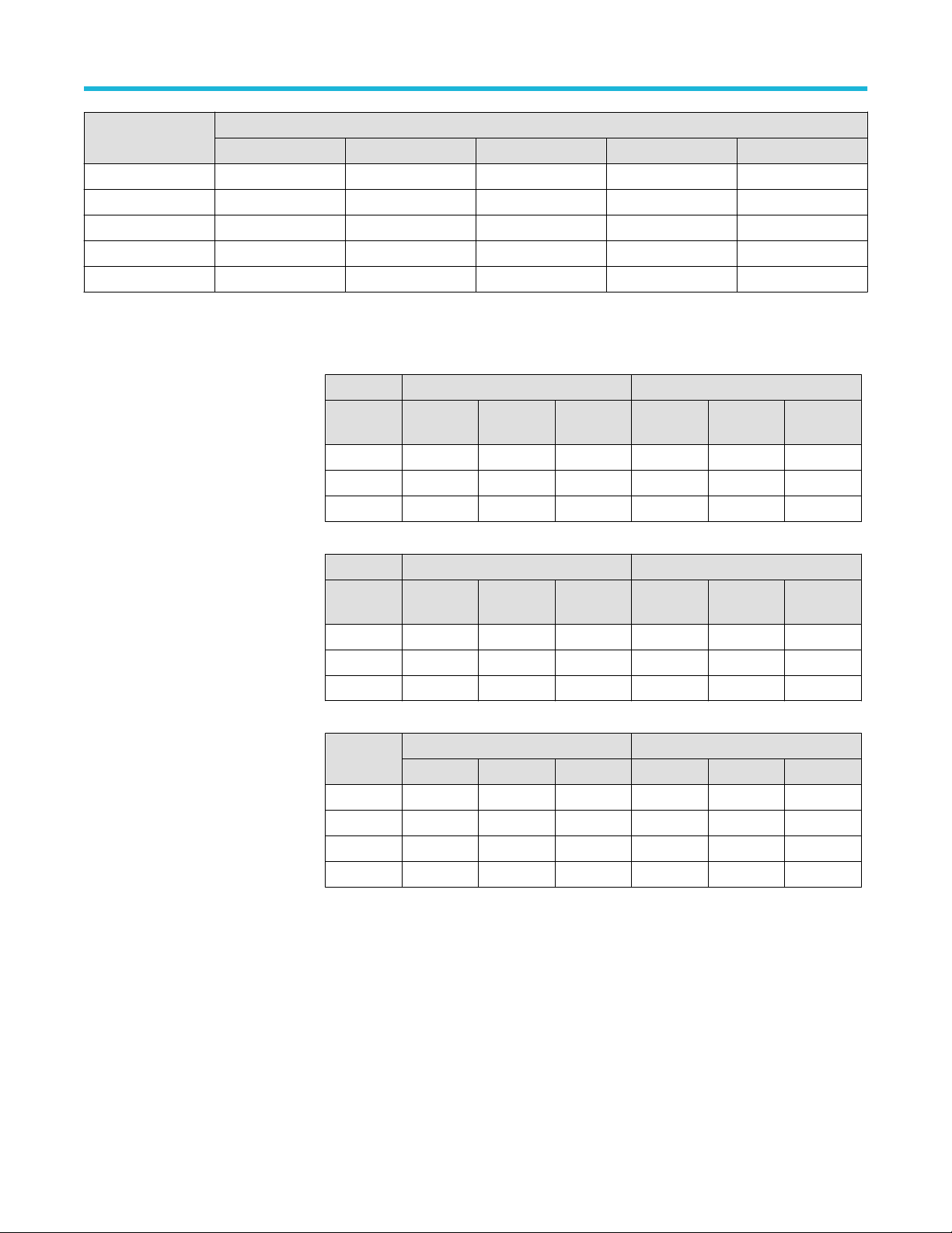
Random Noise
50 Ω, 50 GS/s, Sample mode, RMS 50 Ω, 25 GS/s, HiRes mode, RMS
V/div 10
1 mV 259uV236uV216uV197uV175uV156uV138uV118uV107uV97.4uV72.2uV52.9uV45 uV 42 uV 36.2uV13 uV
2 mV 266uV242uV221uV199uV180uV158uV139uV120uV108uV98.7uV73.2uV53.6uV45.7uV42.6uV36.7uV13.2
5 mV 322uV293uV271uV247uV220uV189uV165uV142uV128uV115uV84.6uV61.3uV52.2uV48.7uV41.9uV15 uV
10 mV 488uV445uV406uV370uV330uV278uV242uV203uV181uV163uV117uV84.8uV70.5uV65.8uV56.7uV20.6
20 mV 850uV775uV707uV645uV581uV478uV412uV346uV309uV275uV195uV141uV116uV107uV93.2uV34.2
50 mV 1.96mV1.79mV1.63mV1.5mV1.34mV1.09mV949uV790uV704uV627uV444uV325uV261uV241uV210uV79 uV
Table continued…
9 GHz 8 GHz 7 GHz 6 GHz 5 GHz 4 GHz 3 GHz 2.5
GHz
2 GHz 1 GHz 500
GHz
MHz
350
MHz
250
MHz
200
MHz20MHz
uV
uV
uV
6 Series B Mixed Signal Oscilloscopes Specifications and Performance Verification 16

Specifications
100mV5.05mV4.55mV4.15mV3.79mV3.38mV2.81mV2.45mV2.06mV1.83mV1.65mV1.17mV858uV705uV658uV573uV203
uV
1 V 38.8mV35.4mV32.6mV29.7mV26.8mV21.8mV18.8mV15.8mV13.9mV12.4mV8.78mV6.51mV5.11mV4.77mV4.15mV1.56
mV
50 Ω, 25 GS/s, Sample mode, RMS 50 Ω, 12.5 GS/s, HiRes mode, RMS
V/div 10
1 mV 281uV253uV223uV199uV179uV162uV138uV117uV108uV96.3uV77.3uV56 uV 47.7uV46.1uV37.9uV13 uV
2 mV 288uV260uV224uV202uV180uV164uV139uV119uV110uV97.6uV72.4uV56.2uV47.3uV46.7uV38 uV 13.3
5 mV 374uV337uV293uV271uV233uV210uV175uV149uV133uV118uV89.6uV68 uV 56.5uV54 uV 44.4uV15.6
10 mV 600uV541uV482uV440uV388uV330uV271uV226uV203uV186uV128uV91.9uV77.3uV74.7uV65.8uV22.6
20 mV 1.08mV976uV890uV793uV691uV595uV486uV398uV363uV320uV226uV162uV133uV120uV106uV41.2
50 mV 2.53mV2.3mV2.1mV1.85mV1.67mV1.4mV1.15mV960uV856uV745uV534uV396uV307uV280uV247uV105
100mV6.14mV5.54mV4.88mV4.4mV3.83mV3.38mV2.71mV2.28mV2.03mV1.81mV1.33mV941uV792uV722uV666uV236
1 V 49.9mV46.1mV42 mV 37 mV 33.4mV28.1mV23.1mV19.2mV17.1mV14.9mV10.8mV7.92mV6.14mV5.6mV4.94mV2.11
9 GHz 8 GHz 7 GHz 6 GHz 5 GHz 4 GHz 3 GHz 2.5
GHz
2 GHz 1 GHz 500
GHz
MHz
350
MHz
250
MHz
200
MHz20MHz
uV
uV
uV
uV
uV
uV
mV
50 Ω, 12.5 GS/s, Sample mode,
RMS
V/div 5 GHz 4 GHz 3 GHz 2.5 GHz 2 GHz 1 GHz 500 MHz 350 MHz 250 MHz 200 MHz 20 MHz
1 mV 162 uV 142 uV 123 uV 109 uV 99.6 uV 73.9 uV 54.8 uV 46.6 uV 43.5 uV 38.8 uV 14.7 uV
2 mV 168 uV 148 uV 127 uV 112 uV 101 uV 74.9 uV 55.5 uV 47.3 uV 44.1 uV 39.3 uV 14.8 uV
5 mV 233 uV 203 uV 173 uV 142 uV 128 uV 92.8 uV 68 uV 56.5 uV 52.8 uV 47 uV 17.7 uV
10 mV 388 uV 334 uV 281 uV 221 uV 197 uV 134 uV 97.4 uV 80.1 uV 74.7 uV 66.6 uV 25.6 uV
20 mV 715 uV 609 uV 518 uV 398 uV 350 uV 237 uV 174 uV 138 uV 129 uV 115 uV 44.6 uV
50 mV 1.71 mV 1.47 mV 1.25 mV 938 uV 836 uV 559 uV 410 uV 322 uV 300 uV 271 uV 105 uV
100 mV 3.92 mV 3.38 mV 2.84 mV 2.23 mV 1.99 mV 1.36 mV 985 uV 801 uV 747 uV 674 uV 256 uV
1 V 34.2 mV 29.4 mV 25 mV 19 mV 16.7 mV 11.1 mV 8.1 mV 6.36 mV 5.94 mV 5.35 mV 2.08 mV
1 MΩ, 12.5 GS/s, HiRes mode, RMS
V/div 500 MHz 350 MHz 250 MHz 200 MHz 20 MHz
1 mV 262 uV 190 uV 153 uV 149 uV 103 uV
Table continued…
50 Ω, 6.25 GS/s, HiRes mode, RMS
6 Series B Mixed Signal Oscilloscopes Specifications and Performance Verification 17

1 MΩ, 12.5 GS/s, HiRes mode, RMS
V/div 500 MHz 350 MHz 250 MHz 200 MHz 20 MHz
2 mV 285 uV 195 uV 155 uV 153 uV 103 uV
5 mV 297 uV 205 uV 161 uV 154 uV 110 uV
10 mV 334 uV 231 uV 186 uV 165 uV 141 uV
20 mV 407 uV 305 uV 257 uV 211 uV 224 uV
50 mV 737 uV 553 uV 528 uV 387 uV 510 uV
100 mV 1.77 mV 1.38 mV 1.18 mV 952 uV 1.13 mV
1 V 19 mV 14.9 mV 13.6 mV 11.3 mV 11.7 mV
Random Noise (Typical)
Specifications
TYP
50 Ω, 50 GS/s, Sample mode, RMS450 Ω, 25 GS/s, HiRes mode, RMS
V/div 10
GHz
9 GHz 8 GHz 7 GHz 6 GHz 5 GHz 4 GHz 3 GHz 2.5
GHz
4
2 GHz 1 GHz 500
MHz
350
MHz
250
MHz
200
MHz20MHz
1 mV 183uV167uV153uV139uV124uV111 uV 97.4uV83.8uV75.6uV68.9uV51.1uV37.5uV31.9uV28.1uV24.2uV8.68
uV
2 mV 188uV172uV156uV141uV127uV112uV98.7uV85 uV 76.6uV69.9uV51.8uV38 uV 32.3uV28.5uV24.5uV8.8 uV
5 mV 228uV208uV192uV175uV156uV134uV117uV101uV90.7uV81.7uV59.9uV43.4uV36.9uV32.5uV28 uV 10.1
uV
10 mV 346uV315uV287uV262uV234uV197uV171uV144uV128uV116uV82.9uV60 uV 49.9uV44 uV 37.9uV13.8
uV
20 mV 602uV549uV501uV457uV412uV338uV291uV245uV219uV195uV138uV99.9uV82.1uV71.5uV62.3uV22.9
uV
50 mV 1.39mV1.27mV1.15mV1.07mV949uV772uV672uV559uV498uV444uV314uV230uV185uV161uV140uV52.8
uV
100mV3.58mV3.22mV2.94mV2.68mV2.39mV1.99mV1.73mV1.46mV1.3mV1.17mV829uV607uV499uV440uV383uV136
uV
1 V 27.4mV25 mV 23.1mV21.1mV19 mV 15.4mV13.3mV11.2mV9.85mV8.78mV6.22mV4.61mV3.62mV3.19mV2.78mV1.04
mV
TYP 50 Ω, 25 GS/s, Sample mode, RMS 50 Ω, 12.5 GS/s, HiRes mode, RMS
V/div 10
9 GHz 8 GHz 7 GHz 6 GHz 5 GHz 4 GHz 3 GHz 2.5
GHz
2 GHz 1 GHz 500
GHz
MHz
350
MHz
250
MHz
200
MHz20MHz
1 mV 199uV179uV158uV141uV127uV114uV97.4uV82.9uV76.5uV68.1uV54.8uV39.7uV33.8uV30.8uV25.3uV8.68
uV
2 mV 204uV184uV158uV143uV127uV116uV98.7uV84 uV 77.5uV69.1uV51.2uV39.8uV33.5uV31.2uV25.4uV8.9 uV
5 mV 264uV238uV208uV192uV165uV149uV124uV105uV93.8uV83.6uV63.4uV48.1uV40 uV 36.1uV29.7uV10.4
uV
Table continued…
4
50 GS sample mode and 25 GS hires mode not available in Fastacq
6 Series B Mixed Signal Oscilloscopes Specifications and Performance Verification 18
Specifications
10 mV 425uV383uV342uV311uV274uV234uV192uV160uV144uV131uV90.9uV65.1uV54.8uV49.9uV44 uV 15.1
uV
20 mV 766uV691uV630uV562uV489uV421uV344uV282uV257uV226uV160uV115uV94.3uV80.3uV70.7uV27.5
uV
50 mV 1.79mV1.63mV1.49mV1.31mV1.18mV994uV817uV680uV606uV528uV378uV280uV217uV187uV165uV70.4
uV
100mV4.35mV3.92mV3.46mV3.11mV2.71mV2.39mV1.92mV1.62mV1.44mV1.28mV941uV666uV560uV482uV445uV158
uV
1 V 35.4mV32.6mV29.7mV26.2mV23.6mV19.9mV16.3mV13.6mV12.1mV10.6mV7.65mV5.6mV4.35mV3.75mV3.3mV1.41
mV
TYP 50 Ω, 12.5 GS/s, Sample mode,
RMS
V/div 5 GHz 4 GHz 3 GHz 2.5 GHz 2 GHz 1 GHz 500 MHz 350 MHz 250 MHz 200 MHz 20 MHz
1 mV 114 uV 101 uV 86.8 uV 77.3 uV 70.5 uV 52.3 uV 38.8 uV 33 uV 29.1 uV 25.9 uV 9.85 uV
2 mV 119 uV 105 uV 90.1 uV 79.3 uV 71.5 uV 53 uV 39.3 uV 33.5 uV 29.5 uV 26.3 uV 9.87 uV
5 mV 165 uV 144 uV 122 uV 101 uV 90.7 uV 65.7 uV 48.1 uV 40 uV 35.3 uV 31.4 uV 11.8 uV
10 mV 274 uV 236 uV 199 uV 156 uV 139 uV 95.2 uV 68.9 uV 56.7 uV 49.9 uV 44.5 uV 17.1 uV
20 mV 506 uV 431 uV 367 uV 282 uV 248 uV 168 uV 123 uV 97.6 uV 86 uV 76.6 uV 29.8 uV
50 mV 1.21 mV 1.04 mV 886 uV 664 uV 592 uV 396 uV 290 uV 228 uV 201 uV 181 uV 70.4 uV
100 mV 2.78 mV 2.39 mV 2.01 mV 1.58 mV 1.41 mV 963 uV 697 uV 567 uV 499 uV 450 uV 171 uV
1 V 24.2 mV 20.8 mV 17.7 mV 13.4 mV 11.8 mV 7.82 mV 5.73 mV 4.5 mV 3.97 mV 3.58 mV 1.39 mV
V/div 1 MΩ, 25 GS/s and 12.5 GS/s, Sample Mode, RMS
500 MHz 350 MHz 250 MHz 200 MHz 20 MHz
1 mV 186 uV 134 uV 108 uV 108 uV 72.2 uV
2 mV 202 uV 138 uV 111 uV 108 uV 78.4 uV
5 mV 220 uV 158 uV 130 uV 124 uV 99.4 uV
10 mV 262 uV 199 uV 183 uV 171 uV 160 uV
20 mV 380 uV 335 uV 282 uV 282 uV 282 uV
50 mV 781 uV 634 uV 704 uV 704 uV 704 uV
100 mV 1.69 mV 1.47 mV 1.41 mV 1.41 mV 1.41 mV
1 V 18.3 mV 15.8 mV 15.6 mV 15.4 mV 14.1 mV
50 Ω, 6.25 GS/s, HiRes mode, RMS
V/div 1 MΩ, 12.5 GS/s and 6.25 GS/s, HiRes Mode, RMS
500 MHz 350 MHz 250 MHz 200 MHz 20 MHz
1 mV 186 uV 134 uV 108 uV 106 uV 73 uV
2 mV 202 uV 138 uV 110 uV 108 uV 73.2 uV
5 mV 210 uV 145 uV 114 uV 109 uV 78.1 uV
Table continued…
6 Series B Mixed Signal Oscilloscopes Specifications and Performance Verification 19
V/div 1 MΩ, 12.5 GS/s and 6.25 GS/s, HiRes Mode, RMS
500 MHz 350 MHz 250 MHz 200 MHz 20 MHz
10 mV 236 uV 163 uV 131 uV 117 uV 99.6 uV
20 mV 288 uV 216 uV 182 uV 149 uV 158 uV
50 mV 522 uV 391 uV 374 uV 274 uV 361 uV
100 mV 1.25 mV 974 uV 838 uV 674 uV 801 uV
1 V 13.4 mV 10.6 mV 9.63 mV 8.01 mV 8.29 mV
Overdrive recovery time
Specifications
500 ns pulse width:
100 us pulse width
TPP1000 Probe
50Ω 400% Overdrive 2000% Overdrive
Vertical
scale
2 mV / div < 50 ns 50 ns 300 ns — — —
10 mV / div < 50 ns 50 ns 300 ns 50 ns 50 ns 400 ns
0.1 V / div < 50 ns 50 ns 300 ns — — —
50Ω 400% Overdrive 2000% Overdrive
Vertical
scale
2 mV / div < 50 ns 50 ns 1 us — — —
10 mV / div < 50 ns 50 ns 1 µs <50 ns 50 ns 150 us
0.1 V / div < 50 ns 50 ns 1 us — — —
Vertical
scale
10 mV / div 20 µs 2.0 ms 2.0 ms 30 µs 50 µs 2.2 ms
20 mV / div 14 µs 2.0 ms 2.0 ms 30 µs 50 µs 110 µs
50 mV / div 12 µs 60 µs 2.0 ms --- --- ---
0.1 V / div 12 µs 60 µs 2.0 ms --- --- ---
5% 1% 0.2% 5% 1% 0.2%
5% 1% 0.2% 5% 1% 0.2%
500% Overdrive 5000% Overdrive
5% 1% 0.2% 5% 1% 0.2%
Crosstalk (Channel Isolation) - 50
Ohm
≥50 dB up to 2 GHz
≥45 dB up to 5 GHz
≥40 dB up to 10 GHz
With channels set to 200 mV/div
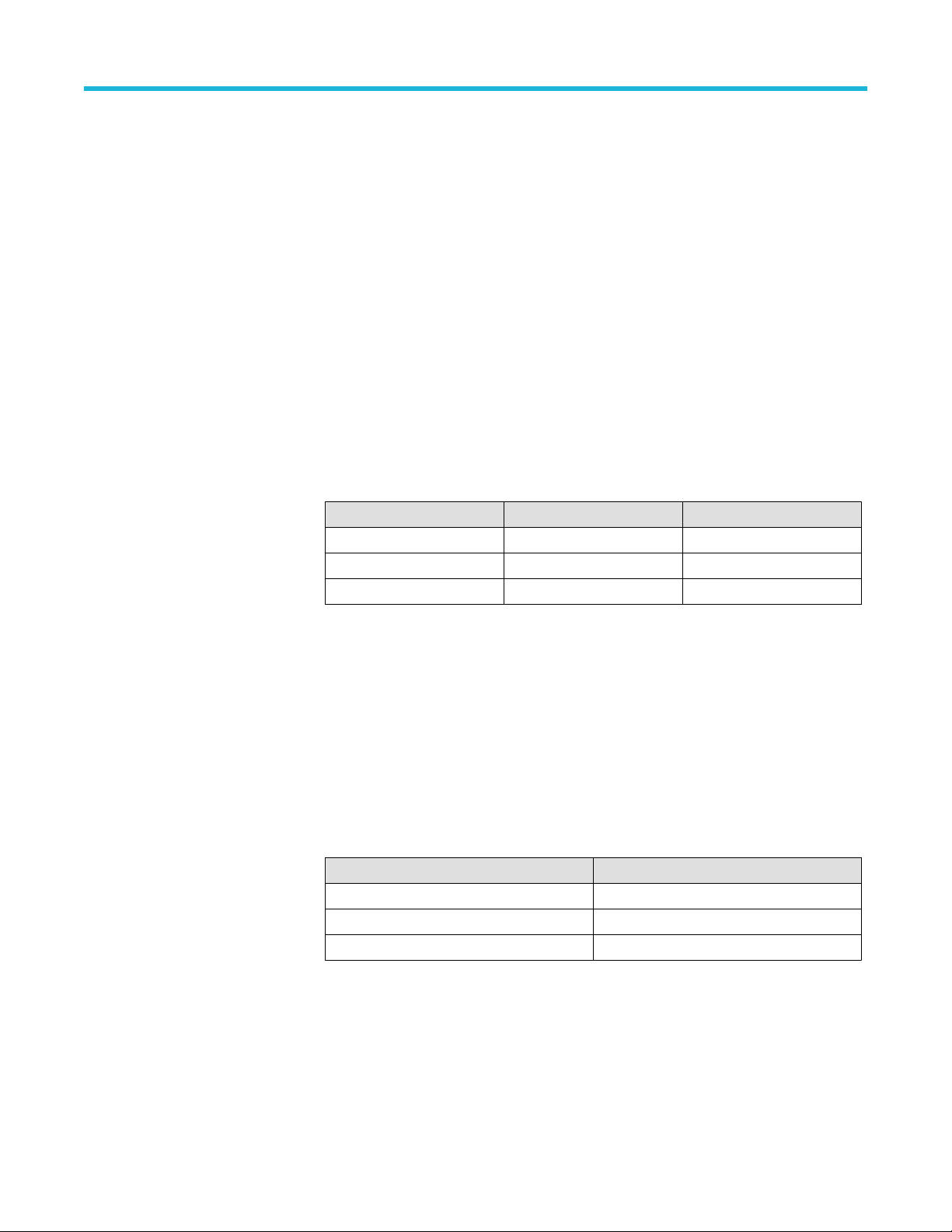
SFDR analog channels
SFDR analog channels, typical A single input tone at -1 dBFS is swept from 10 MHz to bandwidth and the largest error spur is
recorded.
6 Series B Mixed Signal Oscilloscopes Specifications and Performance Verification 20

Bandwidth Sample rate Acquisition mode Vertical scale SFDR
10 GHz 50 GS/s Sample 50 mV/div -45 dB
10 GHz 25 GS/s Sample 50 mV/div -45 dB
5 GHz 12.5 GS/s Sample 50 mV/div -45 dB
5 GHz 25 GS/s Hi Res 50 mV/div -51 dB
5 GHz 12.5 GS/s Hi Res 50 mV/div -51 dB
2 GHz 6.25 GS/s Hi Res 50 mV/div -52 dB
10 GHz 50 GS/s Sample 2 mV/div -42 dB
10 GHz 25 GS/s Sample 2 mV/div -42 dB
5 GHz 12.5 GS/s Sample 2 mV/div -42 dB
5 GHz 25 GS/s Hi Res 2 mV/div -51 dB
5 GHz 12.5 GS/s Hi Res 2 mV/div -51 dB
2 GHz 6.25 GS/s Hi Res 2 mV/div -52 dB
RF front-end
Specifications
Two-tone third intercept point, typical +25 dBm <6 GHz
+20 dBm 6 GHz to 8 GHz
12 dBm 8 GHz to 10 GHz
SFDR, typical -60 dBc for a 1 GHz input in a 5 GHz span with a 3 GHz CF
-70 dBc at 2.35 GHz, 1.5 GHz span
EVM (256 QAM), typical 0.4% rms at 20 M Symbols/s
1.1% rms at 800 M Symbols/s
1.5% rms at 1.2 G Symbols/s
1.6% rms at 2 G Symbols/s
DANL -163 dBm/Hz 10 MHz to 6 GHz, 1 mV/div
-160 dBm/Hz >6 GHz to 10 GHz, 1 mV/div
Harmonic Distortion
Sensitivity/Noise Density, typical -157 dBm/Hz (1 mV/div, -38 dBm, 1.0001 GHz CF, 500 kHz span, 3 kHz RBW)
Phase noise at 1 GHz, typical -118 dBc/Hz 10 kHz offset
Absolute amplitude accuracy, typical ±1 dB (0-8 GHz) for max 10 GHz BW.
Noise figure, typical 1 mv/div, 11 dB 10 MHz to 6 GHz and 14 dB 6 GHz to 10 GHz
SNR/Dynamic Range, typical 112 dB with a 1 GHz signal in a 100 MHz span with 1 kHz RBW ± 20 MHz from the carrier.
2nd harmonic distortion at -58 dBc with a 0 dBm 1 GHz signal.
3rd harmonic distortion at -55 dBc with a 0 dBm 1 GHz signal.
-119 dBc/Hz 100 kHz offset
-132 dBc/Hz 1 MHz offset
-140 dBc/Hz 10 MHz offset
Skew and delay
Digital skew, typical
6 Series B Mixed Signal Oscilloscopes Specifications and Performance Verification 21

Digital-to-Analog skew 1 ns
Digital-to-Digital skew ± 320 ps from bit 0 of any TekVPI + channel to bit 0 of any TekVPI+ channel.
Digital skew within a FlexChannel < 200 ps within any TEKVPI + channel
Specifications
Delay between analog channels, full
bandwidth, typical
Deskew range and resolution -125 ns to +125 ns with a resolution of 40 ps (for Peak Detect and Envelope acquisition
Acquisition Modes Sample, Peak Detect, High Res, Envelope, Average, Fast Frame
Number of digitized bits
≤ 10 ps for any two channels with input impedance set to 50 Ω, DC coupling with equal
Volts/div or above 10 mV/div
modes).
-125 ns to +125 ns with a resolution of 1 ps (for all other acquisition modes).
MSO64B
channels 1 and 3
(2 and 4 off)
MSO66B
channels 1 and 4
(2, 3, 5, and 6
off)
MSO68B
channels 1 and 5
(2, 3, 4, 6, 7, and
8 off)
Sample Rate Acquisition
Mode
50 GS/s Sample 8 10 GHz
25 GS/s Hi Res 12 5 GHz
12.5 GS/s Hi Res 12 5 GHz
6.25 GS/s Hi Res 13 2.5 GHz
3.125 GS/s Hi Res 14 1 GHz
1.5625 GS/s Hi Res 15 500 MHz
625 MS/s Hi Res 16 200 MHz
Digitized Bits Channel
Bandwidth
Peak Detect or Envelope Mode
Minimum Detectable Pulse, typical
MSO64B all
channels
MSO66B
channels 1, 2, 4,
and 5 (3 and 6
off)
MSO68B
channels 1, 2, 5,
and 6 (3, 4, 7,
and 8 off)
MSO66B all
channels
MSO68B all
channels
25 GS/s Sample 8 10 GHz
12.5 GS/s Sample 12 10 GHz
12.5 GS/s Hi Res 12 5 GHz
6.25 GS/s Hi Res 13 2.5 GHz
3.125 GS/s Hi Res 14 1 GHz
1.5625 GS/s Hi Res 15 500 MHz
625 MS/s Hi Res 16 200 MHz
12.5 GS/s Sample 8 5 GHz
6.25 GS/s Sample 12 5 GHz
3.125 GS/s Hi Res 13 1 GHz
1.5625 GS/s Hi Res 14 500 MHz
1.25 GS/s Hi Res 15 500 MHz
312.5 MS/s Hi Res 16 100 MHz
6 Series B Mixed Signal Oscilloscopes Specifications and Performance Verification 22

Specifications
Channels Sample Rate Minimum Pulse Width
MSO64B channels 1 and 3 (2
and 4 off)
MSO66B channels 1 and 4 (2,
3, 5, and 6 off)
MSO68B channels 1 and 5
(2,3, 4, 6, 7, and 8 off)
50 GS/s 160 ps
25 GS/s 160 ps
12.5 GS/s 320 ps
Number of waveforms for average
acquisition mode
MSO64B channels 2 and 4
MSO66B channels 2 and 5 (3
and 6 off)
MSO68B channels 2 and 6 (3,
4, 7 and 8 off)
MSO66B channels 3 and 6
MSO68B channels 3, 4, 7,
and 8
2 to 10,240 Waveforms, default 16 waveforms
TekVPI interface
TekVPI interconnect All analog channel inputs on the front panel conform to the TekVPI+ specification defined in the
TEKPROBE, TEKCONNECT, AND TEKVPI STANDARDS specification.
Total Probe Power
80 W maximum
MSO64B 40 W maximum for channels 1 through 2 and 40 W maximum for channels 3 through 4.
MSO66B 40 W maximum for channels 1 through 3 and 40 W maximum for channels 4 through 6.
MSO68B 40 W maximum for channels 1 through 4 and 40 W maximum for channels 5 through 8.
Probe Power per Channel 5 V Supply: 300 mW (60 mA max)
12 V Supply: 20 W (1.67 A max)
Low-C Passive Probe Support Supports TPP1000 and similar probes
Digital Probe Support Supports TLP058 VPI+ digital probes
Probe User Interface Probe setup menu
Probe menu button support (opens probe setup menu)
Probe warning messages and indicators
Dynamic range indication
Probe bandwidth limiting
6 Series B Mixed Signal Oscilloscopes Specifications and Performance Verification 23
Specifications
Timebase system
✓Timebase factory tolerance Frequency tolerance at factory calibration is ±12 ppb (parts per billion).
At Calibration, 25 °C ambient, over any ≥1 ms interval.
Timebase temperature stability ±20 PPB across the full operating range of 0 °C to 50 °C, after a sufficient soak time at the
temperature.
The instrument needs to soak at a fixed temperature for an extended period of time to insure
the time-base frequency is stable. The following is a worst case estimation for the frequency
error versus the amount of time the instrument has been soaking at a temperature.Max error (in
ppb) = ±10^[log[100/soak time(in hours)]]
For example, a 1 hour soak will have a max frequency error of ±100 ppb, but a 10 hour soak
will have a max frequency error of 10 ppb.
±300 PPB/Year, and will not exceed ±2 PPM over 10 years without calibration.
Calibration will reduce this frequency error to under ±12 PPB
Frequency tolerance change at 25 °C over a periods of 1 year and 10 years.
Sample rate
Sample rate range
High Res sample rate
Channels Sample rate (real time) Sample rate (interpolated)
2 channels 6.25 S/s to 50 GS/s 100 GS/s to 2.5 TS/s
4 channels 6.25 S/s to 25 GS/s 50 GS/s to 2.5 TS/s
8 channels 6.25 S/s to 12.5 GS/s 25 GS/s to 2.5 TS/s
On 4-channel models, the 2 channels with 50 GS/s capability are 1 and 3 (channels 2 and 4
must be off).
On 6-channel models, the2 channels with 50 GS/s capability are 1 and 4 (channels 2, 3, 5, and
6 must be off).
On 8-channel models, the 2 channels with 50 GS/s capability are 1 and 5 (channels 2, 3, 4, 6,
7, and 8 must be off).
On 6-channel models, the 4 channels with 25 GS/s capability are 1,2, 4 and 5 (channels 3 and
6 must be off).
On 8-channel models, the 4 channels with 25 GS/s capability are 1, 2, 5, and 6 (channels 3, 4,
7, and 8 must be off).
Channels Sample rate
2 channels up to 25 GS/s
4 channels up to 12.5 GS/s
8 channels up to 6.25 GS/s
On 4-channel models, the 2 channels with 25 GS/s capability are 1 and 3 (channels 2 and 4
must be off).
On 6-channel models, the 2 channels with 25 GS/s capability are 1 and 4 (channels 2, 3, 5, and
6 must be off).
6 Series B Mixed Signal Oscilloscopes Specifications and Performance Verification 24

Specifications
On 8-channel models, the 2 channels with 25 GS/s capability are 1 and 5 (channels 2, 3, 4, 6,
7, and 8 must be off).
On 6-channel models, the 4 channels with 12.5 GS/s capability are 1, 2, 4, and 5 (channels 3
and 6 must be off).
On 8-channel models, the 4 channels with 12.5 GS/s capability are 1, 2, 5 and 6 (channels 3, 4,
7, and 8 must be off).
Interpolated waveform rate (Sample
mode):
Interpolated waveform rate (High Res
mode):
Record length range Applies to analog and digital channels. All acquisition modes are 1 G maximum record length,
• 2.5 TS/s
• 1 TS/s
• 500 GS/s
• 250 GS/s
• 100 GS/s
• 50 GS/s (only with a 25 GS/s or12.5 GS/s channel on)
• 25 GS/s (only with a 12.5 GS/s channel on)
• 2.5 TS/s
• 1 TS/s
• 500 GS/s
• 250 GS/s
• 100 GS/s
• 50 GS/s
• 25 GS/s (only with a 25 GS/s or12.5 GS/s channel on)
• 12.5 GS/sec (only with a 12.5 GS/s channel on)
down to 1 k minimum record length, adjustable in 1 sample increments.
Standard: 62.5 Mpoints
Option 6-RL-1: 125 Mpoints
Option 6-RL-2: 250 Mpoints
Option 6-RL-3: 500 Mpoints
Option 6-RL-4: 1 Gpoints
Horizontal scale range 40 ps/div to 1000 s/div
The minimum horizontal scale is determined by the record length by dividing the record length
by 10 (because there are 10 divisions on-screen) and then dividing by the maximum sample
rate (2.5 TS/s).
40 ps/div can only be achieved with a 2.5 TS/s sample rate (maximum) and a 1000 point record
length (minimum).The table below shows minimum horizontal scales for a collection of record
lengths.
Record length Minimum Horizontal Scale
1 kS 40 ps/div
10 kS 400 ps/div
100 kS 4 ns/div
Table continued…
6 Series B Mixed Signal Oscilloscopes Specifications and Performance Verification 25

Specifications
Record length Minimum Horizontal Scale
1 MS 40 ns/div
10 MS 400 ns/div
62.5 MS 2.5 us/div
125 MS with optional memory length 5 us/div
250 MS with optional memory length 10 us/div
500 MS with optional memory length 20 us/div
1 GS with optional memory length 40 us/div
1000 s/div is the maximum horizontal scale which limits the acquisition length to 10000 s (2
hours, 46 minutes and 40 seconds).
Below a record length of 62.5 kS, the horizontal scale is further limited. The maximum
horizontal scale can be calculated by dividing the record length by 10 (because there are 10
division on-screen) and then dividing by the minimum sample rate (6.25 S/s).The table below
shows maximum horizontal scales for a collection of record length.
Record length Maximum Horizontal Scale
1 kS 16 s/div
5 kS 80 s/div
10 kS 160 s/div
25 kS 400 s/div
50 kS 800 s/div
62.5 kS 1000 s/div
Sample jitter (Aperture uncertainty),
typical
Time duration Typical jitter
<1 μs 80 fs
<1 ms 130 fs
Delta-time measurement accuracy, typical
Delta-time measurement accuracy,
typical
Formula for DTA:SR1 = Slew Rate (1st Edge) around 1st point in measurement
SR2 = Slew Rate (2nd Edge) around 2nd point in measurement
N = RSS of input-referred noise (volts rms) and Dynamic noise estimate (volts rms).
Dynamic noise estimate*
Note: Dynamic noise is noise that appears with a signal applied (such as distortion or
interleave errors).
tj = aperture uncertainty (sec rms—80fs for short durations)
TBA = timebase accuracy or reference frequency error (which is 20ppb)
6 Series B Mixed Signal Oscilloscopes Specifications and Performance Verification 26
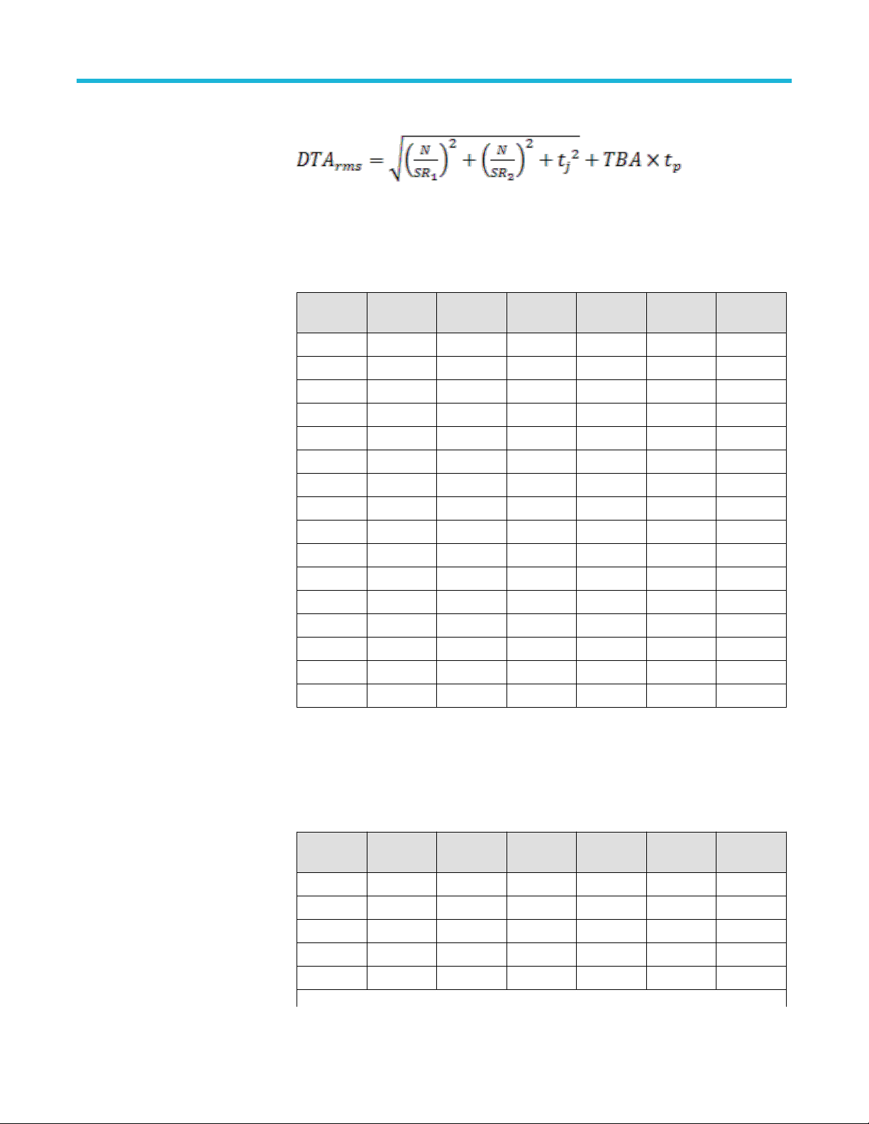
tp = delta-time measurement duration (sec)
Specifications
Delta Time Measurement Accuracy
(DTA), reference example
These limits apply to:
• MSO64B: Channels 1 and 3
• MSO66B: Channels 1 and 4
• MSO68B: Channels 1 and 5 are the only ones used
Volts/div BW Sample
rate
50 mV 10 GHz 50 GHz Sample 5.65 GHz 400 mV 327.78 fs
50 mV 8 GHz 50 GHz Sample 4.52 GHz 400 mV 346.08 fs
50 mV 6 GHz 50 GHz Sample 3.39 GHz 400 mV 383.01 fs
50 mV 5 GHz 25 GHz Hi-Res 2.825 GHz 400 mV 387.37 fs
50 mV 4 GHz 25 GHz Hi-Res 2.26 GHz 400 mV 424.08 fs
50 mV 2.5 GHz 25 GHz Hi-Res 1.4125 GHz 400 mV 512.12 fs
50 mV 2 GHz 25 GHz Hi-Res 1.13 GHz 400 mV 569.94 fs
50 mV 1 GHz 25 GHz Hi-Res 565 MHz 400 mV 802.6 fs
5 mV 10 GHz 50 GHz Sample 5.65 GHz 40 mV 486.58 fs
5 mV 8 GHz 50 GHz Sample 4.52 GHz 40 mV 514.54 fs
5 mV 6 GHz 50 GHz Sample 3.39 GHz 40 mV 561 fs
5 mV 5 GHz 25 GHz Hi-Res 2.825 GHz 40 mV 583.91 fs
5 mV 4 GHz 25 GHz Hi-Res 2.26 GHz 40 mV 637.27 fs
5 mV 2.5 GHz 25 GHz Hi-Res 1.4125 GHz 40 mV 791.51 fs
5 mV 2 GHz 25 GHz Hi-Res 1.13 GHz 40 mV 889.92 fs
5 mV 1 GHz 25 GHz Hi-Res 565 MHz 40 mV 1.29 ps
Sample
mode
Frequency Amplitude
pk-pk
DTA TYP
These limits apply to:
• MSO64B: All channels
• MSO66B: Channels 1, 2, 4, and 5
• MSO68B: Channels 1, 2, 5, and 6 are the only ones used
Volts/div BW Sample
rate
50 mV 10 GHz 25 GHz Sample 5.65 GHz 400 mV 397.32 fs
50 mV 8 GHz 25 GHz Sample 4.52 GHz 400 mV 417.47 fs
50 mV 6 GHz 25 GHz Sample 3.39 GHz 400 mV 448.57 fs
50 mV 5 GHz 12.5 GHz Hi-Res 2.825 GHz 400 mV 460.86 fs
50 mV 4 GHz 12.5 GHz Hi-Res 2.26 GHz 400 mV 483.23 fs
Table continued…
6 Series B Mixed Signal Oscilloscopes Specifications and Performance Verification 27
Sample
mode
Frequency Amplitude
pk-pk
DTA TYP

Specifications
Volts/div BW Sample
rate
50 mV 2.5 GHz 12.5 GHz Hi-Res 1.4125 GHz 400 mV 581.18 fs
50 mV 2 GHz 12.5 GHz Hi-Res 1.13 GHz 400 mV 636.8 fs
50 mV 1 GHz 12.5 GHz Hi-Res 565 MHz 400 mV 904.88 fs
5 mV 10 GHz 25 GHz Sample 5.65 GHz 40 mV 555.49 fs
5 mV 8 GHz 25 GHz Sample 4.52 GHz 40 mV 551.87 fs
5 mV 6 GHz 25 GHz Sample 3.39 GHz 40 mV 589.36 fs
5 mV 5 GHz 12.5 GHz Hi-Res 2.825 GHz 40 mV 637.71 fs
5 mV 4 GHz 12.5 GHz Hi-Res 2.26 GHz 40 mV 668.87 fs
5 mV 2.5 GHz 12.5 GHz Hi-Res 1.4125 GHz 40 mV 814.74 fs
5 mV 2 GHz 12.5 GHz Hi-Res 1.13 GHz 40 mV 907.3 fs
5 mV 1 GHz 12.5 GHz Hi-Res 565 MHz 40 mV 1.36 ps
hese limits apply to:
• MSO66B: All channels
• MSO68B: All channels are used
Volts/div BW Sample
rate
50 mV 5 GHz 12.5 GHz Sample 2.825 GHz 400 mV 536.22 fs
50 mV 4 GHz 12.5 GHz Sample 2.26 GHz 400 mV 580.12 fs
50 mV 2.5 GHz 6.25 GHz Hi-Res 1.4125 GHz 400 mV 620.41 fs
50 mV 2 GHz 6.25 GHz Hi-Res 1.13 GHz 400 mV 690.69 fs
50 mV 1 GHz 6.25 GHz Hi-Res 565 MHz 400 mV 934.61 fs
5 mV 5 GHz 12.5 GHz Sample 2.825 GHz 40 mV 698.23 fs
5 mV 4 GHz 12.5 GHz Sample 2.26 GHz 40 mV 761.47 fs
5 mV 2.5 GHz 6.25 GHz Hi-Res 1.4125 GHz 40 mV 864.09 fs
5 mV 2 GHz 6.25 GHz Hi-Res 1.13 GHz 40 mV 971.89 fs
5 mV 1 GHz 6.25 GHz Hi-Res 565 MHz 40 mV 1.4 ps
Sample
mode
Sample
mode
Frequency Amplitude
pk-pk
Frequency Amplitude
pk-pk
DTA TYP
DTA TYP
6 Series B Mixed Signal Oscilloscopes Specifications and Performance Verification 28

Specifications
Trigger system
Trigger types Edge, Dual Edge, Pulse Width, Timeout, Runt, Logic, Setup & Hold, Rise / Fall Time, Window,
Bus, Parallel, I2C, SPI, RS-232, CAN, LIN, FlexRay, USB LS, USB FS, USB HS, Ethernet
10/100, Audio (I2S/LJ/RJ/TDM), CAN-FD, ARINC 429, MIL-STD-1553, SPMI, SENT
Trigger modes Normal and Auto
Trigger coupling DC, HF Reject, LF Reject, Noise Reject
Trigger holdoff range 0 ns minimum to 10 seconds maximum
Trigger level ranges, typical
Time Range for Glitch, Pulse Width,
Timeout, Time-qualified Runt or Timequalified Window, Transition Time
Trigger
Setup/Hold Violation Trigger, Setup
and Hold Time Ranges
Source Range
Analog Inputs ±5 divs from center of screen
Line N/A
AUX Input ±5 V
40 ps to 20 s
Feature Min Max
Setup Time 0 ns 20 s
Hold Time 0 ns 20 s
Setup + Hold Time 80 ps 22 s
Input coupling on clock and data channels must be the same.
For Setup Time, positive numbers mean a data transition before the clock.
For Hold Time, positive numbers mean a data transition after the clock edge.
Setup + Hold Time is the algebraic sum of the Setup Time and the Hold Time programmed by
the user.
Oscilloscopes Trigger position is equal to the Hold Time value.
Trigger jitter, typical Analog Inputs
• Trigger jitter ≤ 1.5 ps RMS for Sample mode, Edge-type trigger, FastAcq, and Pulse width
modes
• Trigger jitter ≤ 40 ps RMS for non-Edge-type trigger modes
6 Series B Mixed Signal Oscilloscopes Specifications and Performance Verification 29

Specifications
Trigger Bandwidth – Edge, Pulse,
Logic, typical
Trigger level accuracy, DC-coupled,
typical
Model Instrument
bandwidth
MSO6XB 10 GHz 10 GHz 4 GHz
MSO6XB 8 GHz 8 GHz 4 GHz
MSO6XB 6 GHz 6 GHz 4 GHz
MSO6XB 4 GHz, 2.5 GHz, 1
GHz
For signals having rise and fall times ≥10 ns, the limits are as follows:
Source Range
Any Input Channel ±0.20 div
Line N/A
This limit is checked by SPC at very low frequency (nearly DC).
This limit does not include frequency dependent effects, edge type trigger sensitivity not DC
coupled, or trigger position error.
Set the trigger level to the desired value. Using an adjustable DC source, inject a voltage into
the instrument. Adjust the voltage downward (if checking negative slope) or upward (if checking
positive slope) until the scope triggers. The difference between the trigger level setting and the
voltage that actually caused the trigger is the trigger level accuracy.
Edge trigger
bandwidth
Instrument bandwidth Instrument bandwidth
Pulse, Logic trigger
bandwidth
Edge-type Trigger Sensitivity, DCcoupled, typical
Trigger Source Sensitivity
Any input channel, 1 MΩ path
Any input channel, 50 Ω path
Line, 90 V to 264 V line
voltage at 50-60 Hz line
frequency
AUX Trigger 250 mVpp (DC - 400 MHz)
0.5 mv/div to 0.99 mV/div – 5 mV from DC to instrument
bandwidth.
≥ 1 mV/div – The greater of 5 mV or 0.7 div from DC to the
less of 500 MHz or BW.
• 1 mV/div to 1.99 mV/div – 3.5 divisions from DC to 80% of
instrument bandwidth.
• 2 mV/div to 4.99 mV/div - 2 divisions from DC to 80% of
instrument bandwidth.
• ≥ 5 mV/div - 1.5 divisions from DC to 80% of instrument
bandwidth.
103.5 V to 126.5 V
6 Series B Mixed Signal Oscilloscopes Specifications and Performance Verification 30

Specifications
Edge-type trigger sensitivity, not DCcoupled, typical
Logic-type, or Logic-qualified trigger,
or Events-delay sensitivities, DCcoupled, typical
Logic-type triggering, Minimum logic
or Re-arm time, typical
Trigger Coupling Typical Sensitivity
NOISE REJ 2.5 times the DC Coupled limits
HF REJ 1.0 times the DC Coupled limits from DC to 50 kHz.
Attenuates signals above 50 kHz.
LF REJ 1.5 times the DC Coupled limits for frequencies above 50
kHz. Attenuates signals below 50 kHz.
2.0 division, at vertical setting ≥5 mV/div
For all vertical settings, the minimums are:
Triggering Type Pulse Width Re–Arm Time Time overlap needed
for 100% & No
Triggering1
Logic
Time-qualified logic
120 ps + trise
240 ps + trise
5
5
120 ps + trise
240 ps + trise
5
5
≥160 ps/ ≤-40 ps
≥280 ps/ ≤-40 ps
For Logic, time between channels refers to the length of time a logic state derived from more
than one channel must exist to be recognized. For Events, the time is the minimum time
between a main and delayed event that will be recognized if more than one channel is used.
Time accuracy for pulse width and
timeout triggering
Pulse-type Trigger, Minimum Pulse,
Re-arm Time, Transition Time
The limits are as follows:
Time Range Accuracy
320 ps to 20 s ±(40 ps + (Time-Base-Accuracy * Setting))
Time-Base-Accuracy when locked to an external source is equivalent to the accuracy of the
external source.
The limits are as follows:
Pulse class Minimum pulse width Minimum rearm time
Runt
Time–qualified runt
Width
40 ps + trise
40 ps + trise
40 ps + trise
5
5
5
40 ps + trise
40 ps + trise
40 ps + trise
5
5
5
Trigger class Minimum transition time Minimum rearm time
Rise/Fall Time
40 ps + trise
5
40 ps + trise
5
5
trise = calculated rise time
6 Series B Mixed Signal Oscilloscopes Specifications and Performance Verification 31

Specifications
Minimum clock pulse widths for
Setup/Hold time violation trigger,
typical
B Trigger after events, minimum pulse
width, and maximum event frequency,
typical
Pulse-type runt trigger sensitivities,
typical
Pulse-type trigger width and glitch
sensitivities, typical
B Trigger, minimum time arm, and
trigger, typical
For all vertical settings, the minimums are:
Minimum Pulse Width, Clock Active
User's Hold Time7 80 ps + trise
5
6
Minimum Pulse Width, Clock Inactive
80 ps + trise
5
6
For Setup/Hold trigger to work properly, Setup + Hold must be less than the clock period.
Minimum pulse width: 40 ps + trise
5
Maximum Event Frequency: Instrument BW
2.0 division, at vertical setting ≥5 mV/div
2.0 division, at vertical setting ≥5 mV/div
80 ps
For trigger after time, this is the time between the end of the time period and the B trigger
event.
For trigger after events, this is the time between the last A trigger event and the first B trigger
event.
B Trigger after time, time range 40 ps to 20 seconds.
Accuracy = ±(40 ps + (Time-Base-Error * Setting))
B Trigger after events, event range 1 to 65,471
Video-type trigger formats NTSC, PAL, and SECAM
Lowest frequency for successful
45 Hz
operation of “Set Level to 50%”
function, typical
Maximum Triggered Acquisition Rate,
typical
Analysis/measurement mode: Analog or Digital (single channel [Analog or Digital 8-bit channel]
on screen, measurements and math turned off): >40/sec
FastAcq mode (Peak detect or Envelope acquisition mode, OneAnalog channel, with or without
digital channel enabled): >500,000 /s
FastAcq Mode (All other acq modes, One analog channel, with or without digital channel
enabled): 30,000 /s
Fast frame rate (50-point frames): 5,000,000/second in 25 GS/s and 2,500,00/second in 12.5
GS/s
6
Active pulse width is the width of the clock pulse from its active edge (as defined in the Clock Edge setting) to its inactive edge. Inactive pulse width is the width of the
pulse from its inactive edge to its active edge.
7
User Hold Time is the number selected by the user in the "Setup & Hold Times" setting.
6 Series B Mixed Signal Oscilloscopes Specifications and Performance Verification 32

Specifications
Digital channels are not capable of acquiring at the FastAcq rate, but can still be enabled and
acquiring (at a slower rate) while an analog channel is in FastAcq mode.
Maximum Number of Frames in
FastFrame, typical
For system memory depths up to 250 M, and for record length ≥ 1,000 points, maximum
number of frames = system memory depth / record length setting.
For system memory depths of 500 M, and when only channels capable of a maximum sample
rate of ≥ 25 GS/s are used, maximum number of frames = system memory depth / record
length setting.
For system memory depths of 500 M, and when any channels capable of a maximum sample
rate of 12.5 GS/s are used, maximum number of frames is ≥ 250,000.
For system memory depths of 1 G, and when only channels capable of a maximum sample rate
of ≥ 25 GS/s are used, maximum number of frames ≥ system memory depth / record length
setting / 2.
For system memory depths of 1 G, and when only channels capable of a maximum sample rate
of 12.5 GS/s are used, maximum number of frames ≥ system memory depth / record length
setting / 4.
Optional Serial Bus Interface Triggering
I2C Bus
SPI Bus Trigger on: SS Active, Data
Trigger on: Start, Repeated Start, Stop, Missing Ack, Data, Address, or Address & Data
Data Trigger: 1 – 5 Bytes of user-specified data
Address Triggering: 7 & 10 bits of user-specified addresses supported
Maximum Data Rate: 10 Mb/s
Data Trigger: 1 – 16 Bytes of user-specified data
Maximum Data Rate: 20 Mb/s
RS232 Bus Trigger on: Start, End of Packet, Data, Parity Error
Bit Rate: 50 bps – 10 Mbps
Data Bits: 7, 8, or 9
Parity: None, Odd, or Even
CAN Bus Trigger on: Start of Frame, Type of Frame, Identifier, Data, Identifier & Data, End of Frame,
Missing Ack, or Bit Stuffing Error
Frame Type: Data, Remote, Error, Overload
Identifier: Standard (11 bit) and Extended (29 bit) identifiers
Data Trigger: 1 – 8 Bytes of user-specified data, including qualifiers of equal to (=), not equal to
(≠), less than (<), greater than (>), less than or equal to (≤), greater than or equal to (≥).
Maximum Data Rate: 1 Mb/s
CAN-FD Bus Trigger on Start of Frame, Type of Frame (Data, Remote, Error, or Overload), Identifier
(Standard or Extended), Data (1-8 bytes), Identifier and Data, End Of Frame, Error (Missing
Ack, Bit Stuffing Error, FD Form Error, Any Error) on CAN FD buses up to 16 Mb/s
LIN Bus Trigger on: Sync, Identifier, Data, Identifier & Data, Wakeup Frame, Sleep Frame, or Error.
Identifier Trigger: 6 bits of user-specified data, equal to (=).
6 Series B Mixed Signal Oscilloscopes Specifications and Performance Verification 33

Specifications
Data Trigger: 1 – 8 Bytes of user-specified data, including qualifiers of equal to (=), not equal to
(≠), less than (<), greater than (>), less than or equal to (≤), greater than or equal to (≥), inside
range, outside range.
Error Trigger: Sync, Identifier Parity, Checksum.
Maximum Data Rate: 100 kb/s
Flexray Bus Trigger on: Start of Frame, Indicator Bits, Frame ID, Cycle Count, Header Fields, Data, Frame
ID & Data, End ofFrame, or Error.
Indicator Bits: Normal (01XX), Payload (11XX), Null (00XX), Sync (XX10), Startup (XX11).
Frame ID Trigger: 11 bits of user-specified data, including qualifiers of equal to (=), not equal to
(≠), less than (<), greater than (>), less than or equal to (≤), greater than or equal to (≥).
Cycle Count Trigger: 6 bits of user-specified data, including qualifiers of equal to (=), not equal
to (≠), less than (<), greater than (>), less than or equal to (≤), greater than or equal to (≥).
Header Fields Trigger: 40 bits of user-specified data comprising Indicator Bits, Identifier,
Payload Length, Header CRC, and Cycle Count, equal to (=).
Data Trigger: 1 – 16 Bytes of user-specified data, with 0 to 253, or "don't care" bytes of data
offset, including qualifiers of equal to (=), not equal to <>, less than (<), greater than (>), less
than or equal to (≤), greater than or equal to (≥), Inside Range, Outside Range.
End Of Frame: User-chosen types Static, Dynamic (DTS), and All.
Error Trigger: Header CRC, Trailer CRC, Null Frame-Static, Null Frame-Dynamic, Sync Frame,
Startup Frame (No Sync)
Maximum Data Rate: 40 Mb/s
SENT Bus Trigger on Start of Packet, Fast Channel Status and Data, Slow Channel Message ID and Data,
and CRC Errors
SPMI Bus Trigger on Sequence Start Condition, Reset, Sleep, Shutdown, Wakeup, Authenticate, Master
Read, Master Write, Register Read, Register Write, Extended Register Read, Extended
Register Write, Extended Register Read Long, Extended Register Write Long, Device
Descriptor Block Master Read, Device Descriptor Block Slave Read, Register 0 Write, Transfer
Bus Ownership, and Parity Error
Ethernet Bus Trigger On: Start of Frame, MAC Addresses, MAC Length/Type, IP Header, TCP Header, Client
Data, End of Packet, Idle, FCS (CRC) Error, MAC Q-Tag Control Information.
Bit rate: 10 BASE-T, 10 Mbps; 100 BASE-TX, 100 Mbps
USB Bus Trigger On: Sync, Handshake Packet, Special Packet, Error, Token Packet, Data Packet,
Reset, Suspend, Resume, End of Packet.
Data rates supported: High: 480 Mbs, Full: 12 Mbs, Low: 1.5 Mbs
Audio I2S Bus
Trigger on: Word Select, Data
Data Trigger: 32 bits of user-specified data in a left word, right word, or either, including
qualifiers of equal to (=), not equal to (≠), less than (<), greater than (>), less than or equal to
(≤), greater than or equal to (≥), inside range, outside range.
Maximum Data Rate: 12.5Mb/s
Left Justified (LJ)
Trigger on: Word Select, Data
6 Series B Mixed Signal Oscilloscopes Specifications and Performance Verification 34

Data Trigger: 32 bits of user-specified data in a left word, right word, or either, including
qualifiers of equal to (=), not equal to (≠), less than (<), greater than (>), less than or equal to
(≤), greater than or equal to (≥),inside range, outside range.
Maximum Data Rate: 12.5Mb/s
Audio (LJ) Bus Trigger on Word Select, Frame Sync, or Data
Maximum data rate for LJ is 12.5 Mb/s
Audio (RJ) Bus Trigger on: Word Select, Data
Data Trigger: 32 bits of user-specified data in a left word, right word, or either, including
qualifiers of equal to (=), not equal to (≠), less than (<), greater than (>), less than or equal to
(≤), greater than or equal to (≥), inside range, outside range.
Maximum Data Rate: 12.5 Mb/s
Audio (TDM) Bus Trigger on: Frame Sync, Data
Data Trigger: 32 bits of user-specified data in a channel 1-64, including qualifiers of equal to
(=), not equal to (≠), less than (<), greater than (>), less than or equal to (≤), greater than or
equal to (≥), inside range, outside range.
Maximum Data Rate: 25 Mb/s
Specifications
MIL-STD-1553 Bus Trigger on Sync, Command (Transmit/Receive Bit, Parity, Subaddress / Mode, Word Count /
Mode Count, RT Address), Status (Parity, Message Error, Instrumentation, Service Request,
Broadcast Command Received, Busy, Subsystem Flag, Dynamic Bus Control Acceptance,
Terminal Flag), Data, Time (RT/IMG), and Error (Parity Error, Sync Error, Manchester Error,
Non-contiguous Data) on MIL-STD-1553 buses
ARINC 429 Bus Trigger on Word Start, Label, Data, Label and Data, Word End, and Error (Any Error, Parity
Error, Word Error, Gap Error) on ARINC 429 buses up to 1 Mb/s
Analysis
Supported Buses Parallel, I2C, SPI, RS-232, CAN, CAN-FD, LIN, FlexRay, USB LS, USB FS, USB HS, eUSB2,
Ethernet 10/100, Audio (I2S/LJ/RJ/TDM), ARINC 429, MIL-STD-1553, SENT, PSI5, I3C, MDIO,
SPMI, 8b/10b, NRZ, Automotive Ethernet (100Base-T1), Manchester, MIPI D-PHY, Spacewire,
SVID
Available Amplitude Measurements Amplitude, Peak-to-Peak, Mean, Top, Maximum, Positive Overshoot, RMS, Base, Minimum,
Negative Overshoot, AC RMS, Area
Available Time Measurements Period, Data Rate, Skew, Fall Time, Falling Slew Rate, Negative Duty Cycle, Hold Time,
Low Time, Frequency, Positive Pulse Width, Delay, Phase, Burst Width, Time Outside Level,
Duration N-Periods, Unit Interval, Negative Pulse Width, Rise Time, Rising Slew Rate Positive
Duty Cycle, Setup Time, High Time
Available Jitter Measurements TIE, Phase Noise
Measurements Available with DJA AC Common Mode, DC Common Mode, Differential Crossover, T/nT Ratio, Bit High, Bit Low,
Bit Amplitude, SSC Profile, SSC Freq Deviation, SSC Modulation Rate, Jitter Summary, RJ,
RJ-sigmasigma, TJ@BER, DJ, DJ-sigmasigma, PJ, DDJ, DCD, J2, J9, Clock NPJ, SRJ, F/N,
Eye Width, Eye Width@BER, Eye Height, Eye Height@BER, Eye High, Eye Low, Q-Factor
Math Waveform Sources Analog Channels, Math Waveforms, Reference Waveforms, Measurements
6 Series B Mixed Signal Oscilloscopes Specifications and Performance Verification 35

Specifications
Math Waveform Operators +, - ,* , /, <, >, ≥, ≤, =, !=, AND, OR, NAND, NOR, XOR, EQV, square root, absolute value,
integral, derivative, log10, ln, exponential, ceiling, floor, invert, minimum, maximum, sine,
cosine, tangent, arcsin, arccos, arctan, radians, degrees, spectral magnitude, spectral phase,
spectral real, spectral imaginary
Available Cursor Types Waveform, V Bars, H Bars, V&H Bars
Cursor Waveform Sources Analog channels, Digital channels, Math Waveforms, Reference Waveforms. Cursors can apply
to the same waveform ("Same") or to different waveforms ("Split")
Available Plot Types Plot menu: XY, XYZ, Eye Diagram
Measurement menu: Histogram, Time Trend, Spectrum
Measurement Statistics Mean, standard deviation, maximum, minimum, waveform count
Arbitrary function generator
Function types Arbitrary, sine, square, pulse, ramp, triangle, DC level, Gaussian, Lorentz, exponential rise/fall,
sin(x)/x, random noise, Haversine, Cardiac
Amplitude range Values are peak-to-peak voltages
Waveform 50Ω 1MΩ
Arbitrary 10 mV to 2.5 V 20 mV to 5 V
Sine 10 mV to 2.5 V 20 mV to 5 V
Square 10 mV to 2.5 V 20 mV to 5 V
Pulse 10 mV to 2.5 V 20 mV to 5 V
Ramp 10 mV to 2.5 V 20 mV to 5 V
Triangle 10 mV to 2.5 V 20 mV to 5 V
Gaussian 10 mV to 1.25 V 20 mV to 2.5 V
Lorentz 10 mV to 1.2 V 20 mV to 2.4 V
Exponential Rise 10 mV to 1.25 V 20 mV to 2.5 V
Exponential Fall 10 mV to 1.25 V 20 mV to 2.5 V
Sine(x)/x 10 mV to 1.5 V 20 mV to 3.0 V
Random Noise 10 mV to 2.5 V 20 mV to 5 V
Haversine 10 mV to 1.25 V 20 mV to 2.5 V
Cardiac 10 mV to 2.5 V 20 mV to 5 V
Maximum sample rate 250 MS/s
Arbitrary function length 128 K Samples
Sine waveform
Sine Frequency range 0.1 Hz to 50 MHz
SIne Frequency setting resolution 0.1 Hz
Sine and Ramp Frequency
accuracy
Sine amplitude flatness, typical ±0.5 dB (relative to 1 kHz level) at 30 MHz
6 Series B Mixed Signal Oscilloscopes Specifications and Performance Verification 36
130 ppm (frequency ≤ 10 kHz)
50 ppm (frequency > 10 kHz)

Sine total harmonic distortion,
typical
Specifications
±1.0 dB (relative to1 kHz level) at 50 MHz
1% for amplitude ≥ 200 mVpp into 50 ohm load
2.5% for amplitude > 50 mV and < 200 mVpp into 50 ohm load
Sine spurious-free dynamic
40 dB (Vpp ≥0.1 V); 30 dB (Vpp ≥0.02 V), 50 Ohm Load
range, typical
Square and pulse waveform
Frequency range 0.1 Hz to 25 MHz
Frequency setting resolution 0.1 Hz
Square and Pulse Frequency
Accuracy
130 ppm (frequency ≤10 KHz)
50 ppm (frequency > 10 KHz)
Duty cycle range 10% - 90% or 10 ns minimum pulse, whichever is larger Minimum pulse time applies to both on
and off time, so maximum duty cycle will reduce at higher frequencies to maintain 10 ns off time
Square and Pulse Duty cycle
0.1%
resolution
Minimum pulse width, typical 10 ns. This is the minimum time for either on or off duration.
Rise/Fall time, typical 5 ns, 10% - 90%
Square and Pulse Pulse width
100 ps
resolution
Square and Pulse Overshoot,
typical
< 6% for signal steps greater than 100 mV
pp
This applies to overshoot of the positive-going transition (+overshoot) and of the negative-going
(-overshoot) transition
Square and Pulse Asymmetry,
±1% ±5 ns, at 50% duty cycle
typical
Square and Pulse Jitter, typical < 60 ps TIE
, ≥ 100 mVpp amplitude, 40%-60% duty cycle
RMS
Ramp and triangle waveform
Frequency range 0.1 Hz to 500 kHz
Frequency setting resolution 0.1 Hz
Variable symmetry 0% - 100%
Symmetry resolution 0.1%
DC level range ±2.5 V into Hi-Z ±1.25 V into 50 Ω
Gaussian pulse, Haversine, and
5 MHz
Lorentz pulse Maximum frequency
Exponential rise fall maximum
5 MHz
frequency
Sin(x)/x maximum frequency 2 MHz
Random noise amplitude range 20 mVpp to 5 Vpp into Hi-Z
10 mVpp to 2.5 Vpp into 50 Ω
6 Series B Mixed Signal Oscilloscopes Specifications and Performance Verification 37

Specifications
Signal amplitude resolution 1 mV (Hi-Z)
500 μV (50 Ω)
Signal amplitude accuracy ±[ (1.5% of peak-to-peak amplitude setting) + (1.5% of absolute DC offset setting) + 1 mV ]
(frequency = 1 kHz)
DC offset range ±2.5 V into Hi-Z
±1.25 V into 50 Ω
DC offset resolution 1 mV (Hi-Z)
500 μV (50 Ω)
DC offset accuracy ±[ (1.5% of absolute offset voltage setting) + 1 mV ]
Add 3 mV of uncertainty per 10 °C change from 25 °C ambient
Cardiac maximum frequency 500 kHz
Digital volt meter (DVM)
Measurement types DC, AC
Voltage resolution 4 digits
Voltage accuracy DC: ±((1.5% * |reading - offset - position|) + (0.5% * |(offset - position)|) + (0.1 * Volts/div))
De-rated at 0.100% / °C of |reading - offset - position| above 30 °C Signal
± 5 divisions from screen center
AC: ±3% (40 Hz to 1 kHz) with no harmonic content outside 40 Hz to 1 kHz
P-TYP: AC: ±2% (20 Hz to 10 kHz)
For AC measurements, the input channel vertical settings must allow the Vpp input signal to
cover between 4 and 10 divisions and must be fully visible on the screen.
Resolution 8-digits
Accuracy For Slew rates ≥ 3 mv/ns
±(1 count + time base accuracy * input frequency)
The signal must be at least 8 mVpp or 2 div, whichever is greater.
Trigger frequency counter source Any analog input channel.
AC line
Trigger frequency counter max input
frequency
10 Hz to maximum bandwidth of the analog channel
The signal must be at least 8 mVpp or 3 div, whichever is greater.
RMS
+DC, AC
, Trigger frequency Count
RMS
Processor system
Host processor Intel Core i5-8400H @ 2.5 GHz (CoffeeLake 4-core), 16 GB System RAM
Windows operating system Option 6-WIN: Microsoft Windows 10 Enterprise IoT 2016 LTSB (64 bit)
The Windows operating system is available on an optional, customer-installable mass storage
device.
6 Series B Mixed Signal Oscilloscopes Specifications and Performance Verification 38

Specifications
Security options 6-SEC Option: USB and Ethernet communication ports, firmware upgrades and BIOS
password protected.
Password protected I/O ports 6-SEC option enables password protection of USB and Ethernet ports from oscilloscope
application.
6-SEC option has password-protected BIOS
6 Series B Mixed Signal Oscilloscopes Specifications and Performance Verification 39

Specifications
Input/Output port specifications
Ethernet interface An 8-pin RJ-45 connector that supports 10/100/1000 Mb/s
Oscilloscope is intended for use with unshielded twisted-pair ethernet cables (UTP).
DVI connector A 29-pin connector; connect to show the oscilloscope display on an external monitor or
projector.Maximum supported resolution, Windows: 1920 x 1200 at 60 Hz.
Maximum supported resolution, Linux: 1920 x 1080 at 60 Hz.
Only a single TMDS link is provided by the interface.
Analog VGA signaling is not provided by the interface.
VGA Connector A 15-pin, 3-row, D-sub VGA connector
Recommended resolution: 1920x1080 at 60 Hz
DisplayPort connector A 20-pin DisplayPort connector
Maximum supported resolution:
Windows: 2560x1440 @ 60Hz
Linux: 1920 x 1080 @ 60Hz
DP++ Adapter:Maximum supported resolution: 2560x1440 @ 60Hz
Simultaneous displays Up to 3 displays (including the internal display) with a maximum of 1 display per port.
USB interface Three USB host ports on the front of the instrument: two USB 2.0 High Speed ports and one
USB 3.0 SuperSpeed port.
Four USB host ports on the rear of the instruments: two USB 2.0 High Speed ports and two
USB 3.0 SuperSpeed ports.
One USB 3.0 SuperSpeed device port on the rear of the instrument providing USBTMC
support.
Probe compensator
Output Voltage and Frequency Output Voltage Amplitude: 2.5 V ±2% (nominally 0-2.5 V)
Output Frequency: 1 kHz ±25%
Output Source Impedance is nominally 1 kΩ
Auxiliary output, Trigger out, or Reference clock out
AUX OUT Connector and Functional
Modes
AUX OUT Output Voltage Voltage thresholds are listed in the following table:
A single BNC connector.
Acquisition Trigger Out, Reference Clock Out, and AFG Trigger Out.
Characteristic Limits
Vout (HI) ≥2.5 V open circuit; ≥1.0 V into a 50 W load
to ground.
Vout (LO) ≤ 0.7 V into a load of ≤4 mA; ≤0.25 V into a
50 W load to ground.
AUX OUT Acquisition Trigger Jitter Acquisition Trigger Out Jitter: < 50 ps standard deviation
6 Series B Mixed Signal Oscilloscopes Specifications and Performance Verification 40

Specifications
AUX OUT Acquisition Trigger Polarity A leading edge, which is user selectable transition from HIGH to LOW or from LOW to HIGH,
marks the trigger event.
The pulse width is approximately 100 ns.
AUX OUT Reference Clock Reference clock output can be referenced from either the internal clock reference or the
external clock reference.
AUX OUT AFG Trigger The output frequency is dependent the frequency of the AFG signal using the table below:
AFG Signal Frequency AFG Trigger Frequency
≤ 4.9 MHz Signal frequency
>4.9 MHz to 14.7 MHz Signal frequency / 3
>14.7 MHz to 24.5 MHz Signal frequency / 5
>24.5 MHz to 34.3 MHz Signal frequency / 7
>34.3 MHz to 44.1 MHz Signal frequency / 9
>44.1 MHz to 50 MHz Signal frequency / 11
External reference input BNC interface
External reference input
Nominal input frequency 10 MHz
User must select either 10 MHz external (±1 kppm), 10 MHz external (±1ppm), or the internal
reference (default) from the UI.
Frequency Variation Tolerance Low Phase Noise Mode: 9.99999 MHz to 10.00001 MHz (±1
Tracking Mode: 9.99 MHz to 10.01 MHz (± 1000
ppm
)*
Loop Bandwidth of external tracking mode is a function of the PLL loop maximum slew rate
capability, and is not linear. The modulation deviation frequency (±Hz) is dependent upon the
maximum modulation rate (Hz). For example, a deviation of ±50 Hz or less can tolerate any
modulation rate. A deviation of the maximum amount specified for this mode (±10 kHz or 1 kppm)
will tolerate up to 80 Hz of modulation rate. A deviation of ±500Hz will tolerate up to about 1240 Hz
of modulation rate. This is based on a measured instrument response to the reference clock being
modulated. Example measurement is in the below table.
Deviation (+/-Hz) Modulation Rate (Hz) Notes
10000 80
5000 190
2500 320
1000 760
500 1240
250 1720
100 2150
50 Won't lose lock at 50Hz and
ppm
)
below
Sensitivity, typical Vin is 200 mV
Maximum input signal 7 V
pp
up to 7 V
p-p
, using an external 50 Ω termination on the input BNC.
p-p
6 Series B Mixed Signal Oscilloscopes Specifications and Performance Verification 41

Specifications
Impedance 745 Ω ± 20% with 18 pf ± 20% to ground at 10 MHz
AUX IN trigger input impedance
Interface SMA
Input Impedance 50 Ω
Maximum Input Voltage 5 V
Trigger Skew Trigger skew variation improves for pulse input voltages ≥1 V
Trigger Jitter Trigger Jitter ≤ 40 ps RMS for Sample Mode and Edge-Type Trigger
Front panel knob Multipurpose Knob A, Multipurpose Knob B, Trigger Level, Vertical Position, Vertical Scale,
Front Panel Buttons Run/Stop, Single/Seq, Cursors, Fast Acq, High Res, Clear, Force Trigger, Trigger Slope,
Waveform Save Options Analog Waveforms can be saved as: Reference Waveforms, .wfm files, .csv files, .h5 files, .mat
Waveform Recall Options Analog Waveforms can be recalled to reference waveforms from: .wfm files, .csv files, .bin
RMS
.
p-p
When sample rate is ≥25 GS/s and no channels with a maximum sample rate of 12.5 GS/s
(channels 3 or 6 on an MSO66B, or channels 3, 4, 7, or 8 on MSO68B) are used: 200 ps ±200 ps
When sample rate is 12.5 GS/s and at least one channel with a maximum sample rate of 12.5
GS/s (channels 3 or 6 on an MSO66B, or channels 3, 4, 7, or 8 on MSO68B) is used: 7.87 ns ±200
ps
Trigger Jitter ≤ 40 ps RMS for Edge-Type Trigger and FastAcq Mode
Horizontal Position, Horizontal Scale, Wave Inspector (two-tier knob)
Trigger Mode, Vertical Input Selection (one for each analog input), Reference Waveform, Math
Waveform, Bus Waveform, Zoom, Navigate Previous, Navigate Next,Touchscreen Off, Default
Setup (recessed), Save, Autoset (recessed)
files
Digital Waveforms can be saved as: Reference Waveforms, .wfm files, .csv files
Math Waveforms can be saved as: .wfm files, .csv files
(keysight format) files, .trc (LeCroy format) files, .h5 files
Digital Waveforms can be recalled to reference waveforms from: .wfm files, .csvfiles
Math Waveforms can be recalled to reference waveforms from: .wfm files, .csv files
Reference files can be imported from .tr0 binary files.
Display system
Display type Display size: 15.6 inches diagonal
Display type: TFT liquid crystal display (LCD)
Display resolution 1,920 horizontal × 1,080 vertical pixels (High Definition)
Luminance, typical
Color Support 16.2M colors (6-bit RGB+FRC)
Display Options
Persistence Off, Infinite, Variable (Persistence Time is variable) or Auto
Waveform styles Vectors, dots
Graticule Grid, Time, Full or None
Graticule Intensity variable
6 Series B Mixed Signal Oscilloscopes Specifications and Performance Verification 42
500 cd/m2, (Minimum: 400 cd/m2), Display luminance is specified for a new display set at full
brightness.

Display Mode Overlay or Stacked
Interpolation Sin(x)/x or Linear
Waveform Intensity variable
Data storage specifications
Specifications
Nonvolatile memory retention time,
typical
Real-time clock A programmable clock maintaining and reporting the current time in the units of years, months,
Nonvolatile memory capacity
Instrument S/N A 2 kbit EEPROM on the main board that stores the instrument serial number, instrument start up
Companion CvP A pair of 16 Mbit flash memory devices that stores a portion of the Companion FPGA image data.
AFG S/N A 2 kbit EEPROM on the AFG riser card that stores a copy of the instrument serial number which is
Front Panel ID A 64 kbit EEPROM on the LED board that stores the USB vendor ID and device ID for the internal
Front Panel Memory A 4 GB EEPROM on the LED board stores licence options and calibration data
BIOS A 128 Mbit flash memory device that stores the firmware image and device configuration for the
CMOS Memory The host processor chipset includes an integrated memory device, powered by the real-time clock
Memory SPD Each SODIMM (memory module) contains a serial presence detect (SPD) memory device
UCD9248 The instrument includes 3 UCD9248 power supply controllers. Each controller contains an
PMU A power management unit (PMU) microcontroller is used to manage instrument power supplies
Analog Board Controller A microcontroller is used to manage analog board operation. The PMU includes 64 KB of
Carrier FPGA The carrier FPGA stores its own configuration in its own internal 0.33 Mbit nonvolatile memory. The
No time limit for front panel settings, saved waveforms, setups, product licensing, and
calibration constants.
days, hours, minutes, and seconds.
count, total uptime and administration passwords.
One device serves as a backup for the other device.
used to validate the AFG calibration.
front panel controller.
host processor and chipset sub-processors. This includes the Basic Input Output System (BIOS),
Management Engine (ME), Embedded Controller (EC) and Network Interface Controller (NIC). The
Ethernet MAC address is stored in this device.
(RTC) battery, which stores BIOS configuration settings. A customer accessible switch disconnects
the RTC battery from the chipset which clears the contents of the integrated CMOS memory
device.
implemented using an unspecified memory technology. Each SPD device contains the parameter
data specific to its memory module. All SPD devices are treated by the instrument as read only.
The size of a given SPD is unspecified. The 4 channel instrument includes 4 SPD devices.
unspecified quantity of nonvolatile memory that stores various power supply configuration settings.
and hardware initialization. The PMU includes 32 KB of nonvolatile memory for storage of its own
binary executable and redundant storage of UCD9248 device settings.
nonvolatile memory for storage of its own binary executable.
carrier FPGA implements simple "glue logic" for the instrument.
Mass storage device capacity
6 Series B Mixed Signal Oscilloscopes Specifications and Performance Verification 43

Specifications
Linux ≥ 250 GB. Form factor is a 2.5 inch SSD with a SATA-3 interface. Waveforms and setups are
stored on the solid state drive. Provides storage for saved customer data and the Linux operating
system.
Windows (optional) ≥ 500 GB. Form factor is a 2.5 inch SSD with a SATA-3 interface. This drive is customer installable
and provides storage for the Windows operating system option, and saved customer data.
6 Series B Mixed Signal Oscilloscopes Specifications and Performance Verification 44

Power supply system
Power consumption 500 Watts maximum
Fuse rating 12.5 A / 250 VAC
The fuse is not customer replaceable. The line lead is fused, but the neutral lead is not fused.
Safety characteristics
Safety certification US NRTL Listed - UL61010-1 and UL61010-2-030.
Canadian Certification - CAN/CSA-C22.2 No. 61010-1 and CAN/CSA C22.2 No. 61010-2-030.
EU Compliance - Low Voltage Directive 2014-35-EU and EN61010-1 and EN61010-2-030.
International Compliance - IEC 61010-1 and IEC 61010-2-030.
Pollution degree Pollution degree 2, indoor, dry location use only
Environmental specifications
Temperature
Specifications
Operating +0 °C to +50 °C (32 °F to 122 °F)
Non-operating -20 °C to +60 °C (-4 °F to 140 °F)
Humidity
Operating 5% to 90% relative humidity (% RH) at up to +40 °C
5% to 55% RH above +40 °C up to +50 °C, noncondensing
Non-operating 5% to 90% relative humidity (% RH) at up to +60 °C, noncondensing and as limited by a maximum
wet-bulb temperature of +39°C.
Altitude
Operating Up to 3,000 meters (9,843 feet)
Non-operating Up to 12,000 meters (39,370 feet)
Dynamics
Random Vibration: Operating 0.31 GRMS, 5-500 Hz, 10 minutes per axis, 3 axes (30 minutes total).
Mechanical Shock: Operating Half-sine mechanical shocks, 40 g peak amplitude, 11 ms duration, 3 drops in each direction of
each axis (18 total).
6 Series B Mixed Signal Oscilloscopes Specifications and Performance Verification 45

Comparison against MIL-PRF-28800F Environmental Requirements
Specifications
Comparison against MIL-PRF28800F
Environmental Requirements
Environmental Condition
Temperature Nonoperating
Temperature Operating No No Yes Yes
Relative Humidity No No No No
Altitude non-operating Yes Yes Yes Yes
Altitude operating No No No No
Vibration
Non-Operating
Class
1 2 3 4
No No No No
-51 °C/71 °C -51 °C/71 °C -40 °C/71 °C -40 °C/71 °C
-40 °C/55 °C -10 °C/55 °C 0 °C/50 °C +10 °C/40 °C
5% to 95%, 30 °C to 40°C5% to 80%, 30 °C to 40°C5% to 80%, 30 °C to 40°C5% to 80%, 30 °C to 40
5% to 65%,
> 40 °C
4600 m 4600 m 4600 m 4600 m
4600 m 4600 m 4600 m 4600 m
No No Yes Yes
Random Random Random Random
10-500 Hz 0.03 g2/Hz
YES/NO indicates whether the instrument meets the minimum requirement for each
combination of Class and Environmental Condition. The spec's here are those found in
the MIL-PRF-28800F. The corresponding instrument spec's (if any) are listed above. If the
instrument has no corresponding spec an N/A in used. If the MIL-PRF-28800F lists the spec as
"invoked by the purchase description", an IPD is used
°C
5% to 50%
> 40 °C
10-500 Hz 0.03 g2/Hz
5% to 50%,
> 40 °C
5-100 Hz 0.015 g2/Hz
5% to 50%,
> 40 °C
5-100 Hz 0.015 g2/Hz
Overall GRMS: 3.83
Time/Axis: 30 minutes
Bounce N/A N/A N/A N/A
IPD IPD IPD IPD
Table continued…
6 Series B Mixed Signal Oscilloscopes Specifications and Performance Verification 46
Overall GRMS: 3.83
Time/Axis: 30 minutes
100-137Hz -6dB/octave
137-350 Hz 0.0075 g2/Hz
350-500 Hz -6 dB/octave
500 Hz 0.0039 g2/Hz
Overall GRMS: 2.09
Time/Axis: 10 minute
100-137 Hz -6dB/octave
137-350 Hz 0.0075 g2/Hz
350-500 Hz -6 dB/octave
500 Hz 0.0039 g2/Hz
Overall GRMS: 2.09
Time/Axis: 10 minutes

Specifications
Environmental Condition
Class
1 2 3 4
Shock, Functional Yes Yes Yes Yes
30 G
Half-sine, 11 ms pulse
duration, 3 shocks in each
direction of each axis for
18 total shocks.
30 G
Half-sine, 11 ms pulse
duration, 3 shocks in each
direction of each axis for
18 total shocks.
30 G
Half-sine, 11ms pulse
duration, 3 shocks in each
direction of each axis for
18 total shocks.
30 G
Half-sine, 11ms pulse
duration, 3 shocks in each
direction of each axis for
18 total shocks.
Transit Drop No No Yes Yes
46 cm
10 impacts
4 bottom corners and 6
faces
30 cm
10 impacts
4 bottom corners and 6
faces
20 cm
10 impacts
4 bottom corners and 6
faces
20 cm
10 impacts
4 bottom corners and 6
faces
Bench Handling Yes Yes Yes Yes
Lift edge of chassis 45°,
10.16 cm, or point of
balance and drop
Lift edge of chassis 45°,
10.16 cm, or point of
balance and drop
Lift edge of chassis 45°,
10.16 cm, or point of
balance and drop
Lift edge of chassis 45°,
10.16 cm, or point of
balance and drop
Shock High Impact N/A N/A N/A N/A
IPD IPD IPD IPD
Watertight N/A N/A N/A N/A
IPD IPD IPD IPD
Splash Proof N/A N/A N/A N/A
IPD IPD IPD IPD
Drip Proof N/A N/A N/A N/A
IPD IPD IPD IPD
Fungus Resistance N/A N/A N/A N/A
28 days 28 days 28 days 28 days
Salt Exposure
Enclosure
N/A N/A N/A N/A
48 hours 48 hours 48 hours 48 hours
Salt Exposure Structural N/A N/A N/A N/A
48 hours 48 hours 48 hours 48 hours
Explosive Atmosphere N/A N/A N/A N/A
3000m
Dust Resistance N/A N/A N/A N/A
10.7±7.1 g/m
3
Solar Radiation N/A N/A N/A N/A
IPD IPD IPD IPD
6 Series B Mixed Signal Oscilloscopes Specifications and Performance Verification 47

Mechanical specifications
Weight Weight of instruments by model:
• MSO68B 29.8 lbs
• MSO66B 29.6 lbs
• MSO64B 29.2 lbs
• Weight corrections of standard accessories:
• Instrument with protective front cover: + 1.8 lbs
• Instrument with front cover and soft pouch: + 3.4 lbs
• MSO68B Instrument when packaged for shipping: 42.95 lbs
• MSO66B Instrument when packaged for shipping: 42.75 lbs
• MSO64B Instrument when packaged for shipping: 42.35 lbs
• Instrument when configured for rack mount: -2.2 lbs
• Rack Mount: 15 lbs
Dimensions
Requirements that follow are nominal and unboxed:
Unit fits into rackmount configuration (7U)
Height 371 mm (14.6 in) feet folded in, handle folded up
309 mm (12.2in) feet folded in, handle folded to the backside of the instrument
Width 454 mm (17.9 in) from handle hub to handle hub
Depth 205 mm (8.0 in) from back of feet to front of knobs
297.2 mm (11.7in) feet folded in, handle folded to the backside of the instrument
Specifications
Clearance Requirements The clearance requirement for adequate cooling is 2.0 in (50.8 mm) on the right side (when
looking at the front of the instrument) and on the rear of the instrument
Audible Noise Audible noise (fan noise) produced by the instrument at ambient temperature (≤28°C): ≤ 45dB
Kensington Lock Oscilloscope includes a Kensington Lock.
Environmental Compliance
Material Selection - RoHS Compliance EU Directive 2011/65/EU Less than 0.1% by mass (1000 ppm) in homogeneous material
for lead, mercury, hexavalent chromium, polybrominated biphenyls (PBB) and polybrominated
diphenyl ethers (PBDE), and less than 0.01% by mass (100 ppm) of homogeneous material for
cadmium, unless used in an application that is specifically exempted by the EU RoHS Directive
or its amendments.
Complies with RoHS2 Directive 2011/65/EU.
6 Series B Mixed Signal Oscilloscopes Specifications and Performance Verification 48

Specifications
Regional Certifications, Classifications, and Standards List
Meets intent of Directive 2014/30/EU for Electromagnetic compatibility. Compliance was demonstrated to the following specifications as
listed in the Official Journal of the European Communities:
EN 61326-1, EN 61326-2-1 EMC requirements for electrical equipment for measurement, control, and laboratory use.
• CISPR 11. Radiated and conducted emissions, Group 1, Class A
• IEC 61000-4-2. Electrostatic discharge immunity
• IEC 61000-4-3. RF electromagnetic field immunity
• IEC 61000-4-4. Electrical fast transient / burst immunity
• IEC 61000-4-5. Power line surge immunity
• IEC 61000-4-6. Conducted RF immunity
• IEC 61000-4-11. Voltage dips and interruptions immunity
9
10
11
12
8
EN 61000-3-2 AC power line harmonic emissions
EN 61000-3-3 Voltage changes, fluctuations, and flicker
Australia / New Zealand Declaration of Conformity – EMC
Complies with the EMC provision of the Radiocommunications Act per the following standard, in accordance with ACMA.
EN 61326-1 and EN 61326-2-1 Radiated and conducted emissions, Group 1, Class A.
8
10 mV/division to 1 V/division: ≤0.1 division waveform displacement or ≤0.2 division increase in peak-to-peak noise is allowed when the instrument is subjected to
fields and signals as defined in the IEC 61000-4-3.
9
This product is intended for use in nonresidential areas only. Use in residential areas may cause electromagnetic interference.
10
Emissions which exceed the levels required by this standard may occur when this equipment is connected to a test object.
11
For compliance with the EMC standards listed here, high quality shielded interface cables that incorporate low impedance connection between the cable shield and
the connector shell should be used.
12
Equipment may not meet the immunity requirements of applicable listed standards when test leads and/or test probes are connected due to coupling of
electromagnetic interference onto those leads/probes. To minimize the influence of electromagnetic interference, minimize the loop area between the unshielded
portions of signal and associated return leads, and keep leads as far away as possible from electromagnetic disturbance sources. Twisting unshielded test leads
together is an effective way to reduce loop area. For probes, keep the ground return lead as short as possible and close to the probe body. Some probes have
accessory probe tip adapters to accomplish this most effectively. In all cases, observe all safety instructions for the probes or leads used.
6 Series B Mixed Signal Oscilloscopes Specifications and Performance Verification 49

Performance verification procedures
Performance verification procedures
This chapter contains performance verification procedures for the specifications marked with the symbol. The following equipment, or a
suitable equivalent, is required to complete these procedures.
Required equipment
Required equipment Minimum requirements Examples
DC voltage source 3 mV to 4 V, ±0.1% accuracy Fluke 9500B Oscilloscope Calibrator with a
9530 Output Module
Leveled sine wave generator 50 kHz to 10 GHz, ±4% amplitude accuracy
Time mark generator
Logic probe Low capacitance digital probe, 8 channels. TLP058 probe
BNC-to-0.1 inch pin adapter to connect the
logic probe to the signal source.
Digital multimeter (DMM) 0.1% accuracy or better Tektronix DMM4020
One 50 Ω terminator Impedance 50 Ω; connectors: female BNC
One 50 Ω BNC cable Male-to-male connectors Tektronix part number 012-0057-01
Optical mouse USB, PS2 Tektronix part number 119-7054-00
Frequency counter Parts per billion accuracy Tektronix FCA3000 Timer/Counter/Analyzer
80 ms period, ±1.0 x 10⁻⁶ accuracy, rise time
<50 ns
BNC-to-0.1 inch pin adapter; female BNC to
2x16 .01 inch pin headers.
input, male BNC output
Tektronix adapter part number 878-1429-00;
to connect the Fluke 9500B to the TLP058
probe.
Tektronix part number 011-0049-02
You might need additional cables and adapters, depending on the actual test equipment you use.
These procedures cover all MSO64B, MSO66B, and MSO68B models. Disregard checks that do not apply to the specific model you are
testing.
Print the test record on the following pages and use it to record the performance test results for your oscilloscope.
Note: Completion of the performance verification procedure does not update the stored time and date of the latest successful
adjustment. The date and time are updated only when the adjustment procedures in the service manual are successfully
completed.
The performance verification procedures verify the performance of your instrument. They do not adjust your instrument. If your instrument
fails any of the performance verification tests, you should return the instrument to Tektronix for adjustment or repair.
6 Series B Mixed Signal Oscilloscopes Specifications and Performance Verification 50

Performance verification procedures
Test records
Instrument information, self test record
Model Serial # Procedure performed by Date
Test Passed Failed
Self Test
6 Series B Mixed Signal Oscilloscopes Specifications and Performance Verification 51

DC Offset Accuracy test record
Offset Accuracy
Performance
checks Vertical scale Vertical offset
All models
Channel 1 DC Offset
Accuracy, 20 MHz
BW, 50 Ω
Channel 1 DC Offset
Accuracy, 20 MHz
BW, 1 MΩ
Channel 2 DC Offset
Accuracy, 20 MHz
BW, 50 Ω
Channel 2 DC Offset
Accuracy, 20 MHz
BW, 1 MΩ
Channel 3 DC Offset
Accuracy, 20 MHz
BW, 50 Ω
Table continued…
1 mV/div 900 mV 895.3 mV 904.7 mV
1 mV/div -900 mV -904.7 mV -895.3 mV
100 mV/div 5.0 V 4.9663 V 5.0337 V
100 mV/div -5.0 V -5.0337 V -4.9663 V
1 mV/div 900 mV 895.12 mV 904.88 mV
1 mV/div -900 mV -904.88 mV -895.12 mV
100 mV/div 1.0 V 0.975 V 1.025 V
100 mV/div - 1.0 V -1.025 V -0.975 V
500 mV/div 9.0 V 8.855 V 9.145 V
500 mV/div - 9.0 V -9.145 V -8.855 V
1.01 V/div 10.0 V 9.75 V 10.25 V
1.01 V/div -10.0 V -10.25 V -9.75 V
5 V/div 10.0 V 8.95 V 11.05 V
5 V/div -10.0 V -11.05 V -8.95 V
1 mV/div 900 mV 895.3 mV 904.7 mV
1 mV/div -900 mV -904.7 mV -895.3 mV
100 mV/div 5.0 V 4.965 V 5.035 V
100 mV/div -5.0 V -5.035 V -4.965 V
1 mV/div 900 mV 895.3 mV 904.7 mV
1 mV/div -900 mV -904.7 mV -895.3 mV
100 mV/div 1.0 V 0.935 V 1.065 V
100 mV/div - 1.0 V -1.065 V -0.935 V
500 mV/div 9.0 V 8.855 V 9.145 V
500 mV/div - 9.0 V -9.145 V -8.855 V
1.01 V/div 10.0 V 9.3 V 10.7 V
1.01 V/div -10.0 V -10.7 V -9.3 V
5 V/div 10.0 V 8.5 V 11.5 V
5 V/div -10.0 V -11.5 V -8.5 V
1 mV/div 900 mV 895.3 mV 904.7 mV
1 mV/div -900 mV -904.7 mV -895.3 mV
100 mV/div 5.0 V 4.965 V 5.035 V
100 mV/div -5.0 V -5.035 V -4.965 V
Performance verification procedures
13
Low limit Test result High limit
13
Use this value for both the calibrator output and the oscilloscope offset setting.
6 Series B Mixed Signal Oscilloscopes Specifications and Performance Verification 52

Offset Accuracy
Performance
checks Vertical scale Vertical offset
Channel 3 DC Offset
Accuracy, 20 MHz
BW, 1 MΩ
1 mV/div 900 mV 895.3 mV 904.7 mV
1 mV/div -900 mV -904.7 mV -895.3 mV
100 mV/div 1.0 V 0.935 V 1.065 V
100 mV/div - 1.0 V -1.065 V -0.935 V
500 mV/div 9.0 V 8.855 V 9.145 V
500 mV/div - 9.0 V -9.145 V -8.855 V
1.01 V/div 10.0 V 9.3 V 10.7 V
1.01 V/div -10.0 V -10.7 V -9.3 V
5 V/div 10.0 V 8.5 V 11.5 V
5 V/div -10.0 V -11.5 V -8.5 V
Channel 4 DC Offset
Accuracy, 20 MHz
BW, 50 Ω
1 mV/div 900 mV 895.3 mV 904.7 mV
1 mV/div -900 mV -904.7 mV -895.3 mV
100 mV/div 5.0 V 4.965 V 5.035 V
100 mV/div -5.0 V -5.035 V -4.965 V
Channel 4 DC Offset
Accuracy, 20 MHz
BW, 1 MΩ
1 mV/div 900 mV 895.3 mV 904.7 mV
1 mV/div -900 mV -904.7 mV -895.3 mV
100 mV/div 1.0 V 0.935 V 1.065 V
100 mV/div - 1.0 V -1.065 V -0.935 V
500 mV/div 9.0 V 8.855 V 9.145 V
500 mV/div - 9.0 V -9.145 V -8.855 V
1.01 V/div 10.0 V 9.3 V 10.7 V
1.01 V/div -10.0 V -10.7 V -9.3 V
5 V/div 10.0 V 8.5 V 11.5 V
5 V/div -10.0 V -11.5 V -8.5 V
Channel 5 DC Offset
Accuracy, 20 MHz
BW, 50 Ω
1 mV/div 900 mV 895.3 mV 904.7 mV
1 mV/div -900 mV -904.7 mV -895.3 mV
100 mV/div 5.0 V 4.965 V 5.035 V
100 mV/div -5.0 V -5.035 V -4.965 V
Table continued…
Performance verification procedures
13
Low limit Test result High limit
13
Use this value for both the calibrator output and the oscilloscope offset setting.
6 Series B Mixed Signal Oscilloscopes Specifications and Performance Verification 53

Offset Accuracy
Performance
checks Vertical scale Vertical offset
Channel 5 DC Offset
Accuracy, 20 MHz
BW, 1 MΩ
1 mV/div 900 mV 895.3 mV 904.7 mV
1 mV/div -900 mV -904.7 mV -895.3 mV
100 mV/div 1.0 V 0.975 V 1.025 V
100 mV/div - 1.0 V -1.025 V -0.975 V
500 mV/div 9.0 V 8.855 V 9.145 V
500 mV/div - 9.0 V -9.145 V -8.855 V
1.01 V/div 10.0 V 9.75 V 10.25 V
1.01 V/div -10.0 V -10.25 V -9.75 V
5 V/div 10.0 V 8.95 V 11.05 V
5 V/div -10.0 V -11.05 V -8.95 V
Channel 6 DC Offset
Accuracy, 20 MHz
BW, 50 Ω
1 mV/div 900 mV 895.3 mV 904.7 mV
1 mV/div -900 mV -904.7 mV -895.3 mV
100 mV/div 5.0 V 4.965 V 5.035 V
100 mV/div -5.0 V -5.035 V -4.965 V
Channel 6 DC Offset
Accuracy, 20 MHz
BW, 1 MΩ
1 mV/div 900 mV 895.3 mV 904.7 mV
1 mV/div -900 mV -904.7 mV -895.3 mV
100 mV/div 1.0 V 0.975 V 1.025 V
100 mV/div - 1.0 V -1.025 V -0.975 V
500 mV/div 9.0 V 8.855 V 9.145 V
500 mV/div - 9.0 V -9.145 V -8.855 V
1.01 V/div 10.0 V 9.75 V 10.25 V
1.01 V/div -10.0 V -10.25 V -9.75 V
5 V/div 10.0 V 8.95 V 11.05 V
5 V/div -10.0 V -11.05 V -8.95 V
Channel 7 DC Offset
Accuracy, 20 MHz
BW, 50 Ω
1 mV/div 900 mV 895.3 mV 904.7 mV
1 mV/div -900 mV -904.7 mV -895.3 mV
100 mV/div 5.0 V 4.965 V 5.035 V
100 mV/div -5.0 V -5.035 V -4.965 V
Table continued…
Performance verification procedures
13
Low limit Test result High limit
13
Use this value for both the calibrator output and the oscilloscope offset setting.
6 Series B Mixed Signal Oscilloscopes Specifications and Performance Verification 54

Offset Accuracy
Performance
checks Vertical scale Vertical offset
Channel 7 DC Offset
Accuracy, 20 MHz
BW, 1 MΩ
1 mV/div 900 mV 895.3 mV 904.7 mV
1 mV/div -900 mV -904.7 mV -895.3 mV
100 mV/div 1.0 V 0.975 V 1.025 V
100 mV/div - 1.0 V -1.025 V -0.975 V
500 mV/div 9.0 V 8.855 V 9.145 V
500 mV/div - 9.0 V -9.145 V -8.855 V
1.01 V/div 10.0 V 9.75 V 10.25 V
1.01 V/div -10.0 V -10.25 V -9.75 V
5 V/div 10.0 V 8.95 V 11.05 V
5 V/div -10.0 V -11.05 V -8.95 V
Channel 8 DC Offset
Accuracy, 20 MHz
BW, 50 Ω
1 mV/div 900 mV 895.3 mV 904.7 mV
1 mV/div -900 mV -904.7 mV -895.3 mV
100 mV/div 5.0 V 4.965 V 5.035 V
100 mV/div -5.0 V -5.035 V -4.965 V
Channel 8 DC Offset
Accuracy, 20 MHz
BW, 1 MΩ
1 mV/div 900 mV 895.3 mV 904.7 mV
1 mV/div -900 mV -904.7 mV -895.3 mV
100 mV/div 1.0 V 0.975 V 1.025 V
100 mV/div - 1.0 V -1.025 V -0.975 V
500 mV/div 9.0 V 8.855 V 9.145 V
500 mV/div - 9.0 V -9.145 V -8.855 V
1.01 V/div 10.0 V 9.75 V 10.25 V
1.01 V/div -10.0 V -10.25 V -9.75 V
5 V/div 10.0 V 8.95 V 11.05 V
5 V/div -10.0 V -11.05 V -8.95 V
Performance verification procedures
13
Low limit Test result High limit
13
Use this value for both the calibrator output and the oscilloscope offset setting.
6 Series B Mixed Signal Oscilloscopes Specifications and Performance Verification 55

Performance verification procedures
Analog Bandwidth test record
Analog Bandwidth
Performance checks
Bandwidth at
Channel Impedance Vertical scale Horizontal scale
V
in-pp
All models
Channel 1 50 Ω 1 mV/div 1 ns/div ≥ 0.707
2 mV/div 1 ns/div ≥ 0.707
4 mV/div 1 ns/div ≥ 0.707
10 mV/div 1 ns/div ≥ 0.707
25 mV/div 1 ns/div ≥ 0.707
50 mV/div 1 ns/div ≥ 0.707
100 mV/div 1 ns/div ≥ 0.707
Channel 1 1 MΩ,
typical
1 mV/div 1 ns/div ≥ 0.707
2 mV/div 1 ns/div ≥ 0.707
4 mV/div 1 ns/div ≥ 0.707
10 mV/div 1 ns/div ≥ 0.707
25 mV/div 1 ns/div ≥ 0.707
50 mV/div 1 ns/div ≥ 0.707
100 mV/div 1 ns/div ≥ 0.707
Channel 2 50 Ω 1 mV/div 1 ns/div ≥ 0.707
2 mV/div 1 ns/div ≥ 0.707
4 mV/div 1 ns/div ≥ 0.707
10 mV/div 1 ns/div ≥ 0.707
25 mV/div 1 ns/div ≥ 0.707
50 mV/div 1 ns/div ≥ 0.707
100 mV/div 1 ns/div ≥ 0.707
Channel 2 1 MΩ,
1 mV/div
1 ns/div
typical
2 mV/div 1 ns/div ≥ 0.707
4 mV/div 1 ns/div ≥ 0.707
10 mV/div 1 ns/div ≥ 0.707
25 mV/div 1 ns/div ≥ 0.707
50 mV/div 1 ns/div ≥ 0.707
100 mV/div 1 ns/div ≥ 0.707
Table continued…
V
bw-pp
Limit
≥ 0.707
Test result
Gain = V
bw-pp/Vin-pp
6 Series B Mixed Signal Oscilloscopes Specifications and Performance Verification 56

Performance verification procedures
Analog Bandwidth
Performance checks
Bandwidth at
Channel Impedance Vertical scale Horizontal scale
V
in-pp
V
bw-pp
Limit
Channel 3 50 Ω 1 mV/div 1 ns/div ≥ 0.707
2 mV/div 1 ns/div ≥ 0.707
4 mV/div 1 ns/div ≥ 0.707
10 mV/div 1 ns/div ≥ 0.707
25 mV/div 1 ns/div ≥ 0.707
50 mV/div 1 ns/div ≥ 0.707
100 mV/div 1 ns/div ≥ 0.707
Channel 3 1 MΩ,
typical
1 mV/div 1 ns/div ≥ 0.707
2 mV/div 1 ns/div ≥ 0.707
4 mV/div 1 ns/div ≥ 0.707
10 mV/div 1 ns/div ≥ 0.707
25 mV/div 1 ns/div ≥ 0.707
50 mV/div 1 ns/div ≥ 0.707
100 mV/div 1 ns/div ≥ 0.707
Channel 4 50 Ω 1 mV/div 1 ns/div ≥ 0.707
2 mV/div 1 ns/div ≥ 0.707
4 mV/div 1 ns/div ≥ 0.707
10 mV/div 1 ns/div ≥ 0.707
25 mV/div 1 ns/div ≥ 0.707
50 mV/div 1 ns/div ≥ 0.707
100 mV/div 1 ns/div ≥ 0.707
Channel 4 1 MΩ,
typical
1 mV/div 1 ns/div ≥ 0.707
2 mV/div 1 ns/div ≥ 0.707
4 mV/div 1 ns/div ≥ 0.707
10 mV/div 1 ns/div ≥ 0.707
25 mV/div 1 ns/div ≥ 0.707
50 mV/div 1 ns/div ≥ 0.707
100 mV/div 1 ns/div ≥ 0.707
Table continued…
Test result
Gain = V
bw-pp/Vin-pp
6 Series B Mixed Signal Oscilloscopes Specifications and Performance Verification 57

Performance verification procedures
Analog Bandwidth
Performance checks
Bandwidth at
Channel Impedance Vertical scale Horizontal scale
V
in-pp
V
bw-pp
Limit
Channel 5 50 Ω 1 mV/div 1 ns/div ≥ 0.707
2 mV/div 1 ns/div ≥ 0.707
4 mV/div 1 ns/div ≥ 0.707
10 mV/div 1 ns/div ≥ 0.707
25 mV/div 1 ns/div ≥ 0.707
50 mV/div 1 ns/div ≥ 0.707
100 mV/div 1 ns/div ≥ 0.707
Channel 5 1 MΩ,
typical
1 mV/div 1 ns/div ≥ 0.707
2 mV/div 1 ns/div ≥ 0.707
4 mV/div 1 ns/div ≥ 0.707
10 mV/div 1 ns/div ≥ 0.707
25 mV/div 1 ns/div ≥ 0.707
50 mV/div 1 ns/div ≥ 0.707
100 mV/div 1 ns/div ≥ 0.707
Channel 6 50 Ω 1 mV/div 1 ns/div ≥ 0.707
2 mV/div 1 ns/div ≥ 0.707
4 mV/div 1 ns/div ≥ 0.707
10 mV/div
1 ns/div
≥ 0.707
Test result
Gain = V
bw-pp/Vin-pp
Channel 6 1 MΩ,
typical
Table continued…
25 mV/div 1 ns/div ≥ 0.707
50 mV/div 1 ns/div ≥ 0.707
100 mV/div 1 ns/div ≥ 0.707
1 mV/div 1 ns/div ≥ 0.707
2 mV/div 1 ns/div ≥ 0.707
4 mV/div 1 ns/div ≥ 0.707
10 mV/div 1 ns/div ≥ 0.707
25 mV/div 1 ns/div ≥ 0.707
50 mV/div 1 ns/div ≥ 0.707
100 mV/div 1 ns/div ≥ 0.707
6 Series B Mixed Signal Oscilloscopes Specifications and Performance Verification 58

Performance verification procedures
Analog Bandwidth
Performance checks
Bandwidth at
Channel Impedance Vertical scale Horizontal scale
V
in-pp
V
bw-pp
Limit
Channel 7 50 Ω 1 mV/div 1 ns/div ≥ 0.707
2 mV/div 1 ns/div ≥ 0.707
4 mV/div 1 ns/div ≥ 0.707
10 mV/div 1 ns/div ≥ 0.707
25 mV/div 1 ns/div ≥ 0.707
50 mV/div 1 ns/div ≥ 0.707
100 mV/div 1 ns/div ≥ 0.707
Channel 7 1 MΩ,
typical
1 mV/div 1 ns/div ≥ 0.707
2 mV/div 1 ns/div ≥ 0.707
4 mV/div 1 ns/div ≥ 0.707
10 mV/div 1 ns/div ≥ 0.707
25 mV/div 1 ns/div ≥ 0.707
50 mV/div 1 ns/div ≥ 0.707
100 mV/div 1 ns/div ≥ 0.707
Channel 8 50 Ω 1 mV/div 1 ns/div ≥ 0.707
2 mV/div 1 ns/div ≥ 0.707
4 mV/div 1 ns/div ≥ 0.707
10 mV/div 1 ns/div ≥ 0.707
25 mV/div 1 ns/div ≥ 0.707
50 mV/div 1 ns/div ≥ 0.707
100 mV/div 1 ns/div ≥ 0.707
Channel 8 1 MΩ,
typical
1 mV/div 1 ns/div ≥ 0.707
2 mV/div 1 ns/div ≥ 0.707
4 mV/div 1 ns/div ≥ 0.707
10 mV/div 1 ns/div ≥ 0.707
25 mV/div 1 ns/div ≥ 0.707
50 mV/div 1 ns/div ≥ 0.707
100 mV/div 1 ns/div ≥ 0.707
Test result
Gain = V
bw-pp/Vin-pp
6 Series B Mixed Signal Oscilloscopes Specifications and Performance Verification 59
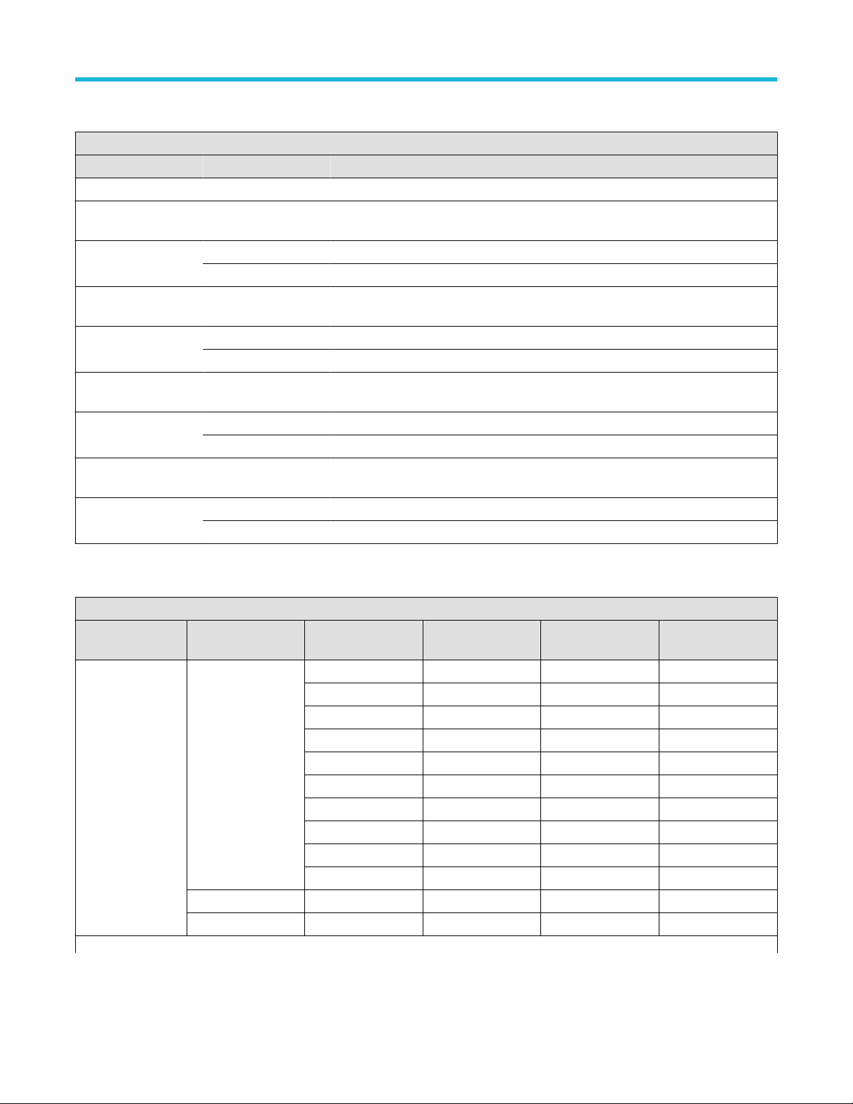
Performance verification procedures
Input impedance test record
Input Impedance
Performance checks Vertical scale Low limit Test result High limit
All models
Channel 1 Input
Impedance, 1 MΩ
Channel 1 Input
Impedance, 50 Ω
Channel 2 Input
Impedance, 1 MΩ
Channel 2 Input
Impedance, 50 Ω
Channel 3 Input
Impedance, 1 MΩ
Channel 3 Input
Impedance, 50 Ω
Channel 4 Input
Impedance, 1 MΩ
Channel 4, Input
Impedance, 50 Ω
100 mV/div 990 kΩ 1.01 MΩ
10 mV/div 48.5 Ω 51.5 Ω
100 mV/div 48.5 Ω 51.5 Ω
100 mV/div 990 kΩ 1.01 MΩ
10 mV/div 48.5 Ω 51.5 Ω
100 mV/div 48.5 Ω 51.5 Ω
100 mV/div 990 kΩ 1.01 MΩ
10 mV/div 48.5 Ω 51.5 Ω
100 mV/div 48.5 Ω 51.5 Ω
100 mV/div 990 kΩ 1.01 MΩ
10 mV/div 48.5 Ω 51.5 Ω
100 mV/div 48.5 Ω 51.5 Ω
DC Gain Accuracy test record
DC Gain Accuracy
Performance
checks Bandwidth Vertical scale Low limit Test result High limit
Channel 1 DC Gain
Accuracy, 0 V offset,
0 V vertical position,
50 Ω
Table continued…
20 MHz 1 mV/div -4% 4%
2 mV/div -2% 2%
5 mV/div -2% 2%
10 mV/div -2% 2%
20 mV/div -2% 2%
50 mV/div -2% 2%
100 mV/div -2% 2%
200 mV/div -2% 2%
500 mV/div -2% 2%
1 V/div -2% 2%
250 MHz 20 mV/div -2% 2%
FULL 20 mV/div -2% 2%
6 Series B Mixed Signal Oscilloscopes Specifications and Performance Verification 60
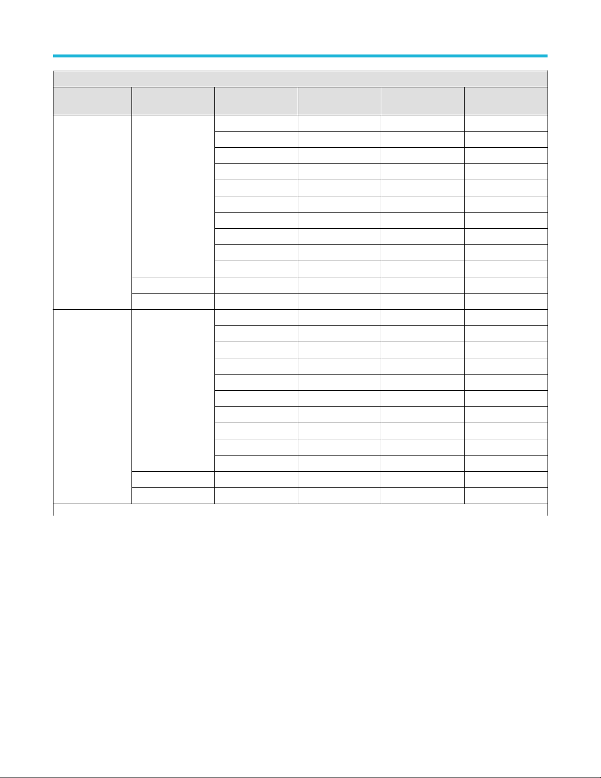
Performance verification procedures
DC Gain Accuracy
Performance
checks Bandwidth Vertical scale Low limit Test result High limit
Channel 1 DC Gain
Accuracy, 0 V offset,
0 V vertical position,
1 MΩ
Channel 2 DC Gain
Accuracy, 0 V offset,
0 V vertical position,
50 Ω
Table continued…
20 MHz 1 mV/div -2.5% 2.5%
2 mV/div -2% 2%
5 mV/div -2% 2%
10 mV/div -2% 2%
20 mV/div -2% 2%
50 mV/div -2% 2%
100 mV/div -2% 2%
200 mV/div -2% 2%
500 mV/div -2% 2%
1 V/div -2% 2%
250 MHz 20 mV/div -2% 2%
FULL 20 mV/div -2% 2%
20 MHz 1 mV/div -4% 4%
2 mV/div -2% 2%
5 mV/div -2% 2%
10 mV/div -2% 2%
20 mV/div -2% 2%
50 mV/div -2% 2%
100 mV/div -2% 2%
200 mV/div -2% 2%
500 mV/div -2% 2%
1 V/div -2% 2%
250 MHz 20 mV/div -2% 2%
FULL 20 mV/div -2% 2%
6 Series B Mixed Signal Oscilloscopes Specifications and Performance Verification 61

Performance verification procedures
DC Gain Accuracy
Performance
checks Bandwidth Vertical scale Low limit Test result High limit
Channel 2 DC Gain
Accuracy, 0 V offset,
0 V vertical position,
1 MΩ
Channel 3 DC Gain
Accuracy, 0 V offset,
0 V vertical position,
50 Ω
Table continued…
20 MHz 1 mV/div -2.5% 2.5%
2 mV/div -2% 2%
5 mV/div -2% 2%
10 mV/div -2% 2%
20 mV/div -2% 2%
50 mV/div -2% 2%
100 mV/div -2% 2%
200 mV/div -2% 2%
500 mV/div -2% 2%
1 V/div -2% 2%
250 MHz 20 mV/div -2% 2%
FULL 20 mV/div -2% 2%
20 MHz 1 mV/div -4% 4%
2 mV/div -2% 2%
5 mV/div -2% 2%
10 mV/div -2% 2%
20 mV/div -2% 2%
50 mV/div -2% 2%
100 mV/div -2% 2%
200 mV/div -2% 2%
500 mV/div -2% 2%
1 V/div -2% 2%
250 MHz 20 mV/div -2% 2%
FULL 20 mV/div -2% 2%
6 Series B Mixed Signal Oscilloscopes Specifications and Performance Verification 62

Performance verification procedures
DC Gain Accuracy
Performance
checks Bandwidth Vertical scale Low limit Test result High limit
Channel 3 DC Gain
Accuracy, 0 V offset,
0 V vertical position,
1 MΩ
Channel 4 DC Gain
Accuracy, 0 V offset,
0 V vertical position,
50 Ω
20 MHz 1 mV/div -2.5% 2.5%
2 mV/div -2% 2%
5 mV/div -2% 2%
10 mV/div -2% 2%
20 mV/div -2% 2%
50 mV/div -2% 2%
100 mV/div -2% 2%
200 mV/div -2% 2%
500 mV/div -2% 2%
1 V/div -2% 2%
250 MHz 20 mV/div -2% 2%
FULL 20 mV/div -2% 2%
20 MHz 1 mV/div -4% 4%
2 mV/div -2% 2%
5 mV/div -2% 2%
10 mV/div -2% 2%
20 mV/div -2% 2%
50 mV/div -2% 2%
100 mV/div -2% 2%
200 mV/div -2% 2%
500 mV/div -2% 2%
1 V/div -2% 2%
250 MHz 20 mV/div -2%
2%
FULL 20 mV/div -2% 2%
Channel 4 DC Gain
Accuracy, 0 V offset,
0 V vertical position,
1 MΩ
6 Series B Mixed Signal Oscilloscopes Specifications and Performance Verification 63
20 MHz 1 mV/div -2.5% 2.5%
2 mV/div -2% 2%
5 mV/div -2% 2%
10 mV/div -2% 2%
20 mV/div -2% 2%
50 mV/div -2% 2%
100 mV/div -2% 2%
200 mV/div -2% 2%
500 mV/div -2% 2%
1 V/div -2% 2%
250 MHz 20 mV/div -2% 2%
FULL 20 mV/div -2% 2%

Random Noise, sample acquisition mode test record
Random Noise, sample acquisition mode: MSO68B, MSO66B, MSO64B
Performance checks 50 Ω, 50 GS/s
Performance verification procedures
V/div
Bandwidth
14
Test result (mV) High limit
Models: MSO68B, MSO66B, MSO64B
Channel 1 1 mV/div 10 GHz limit 259 uV
9 GHz limit 236 uV
8 GHz limit 216 uV
7 GHz limit 197 uV
6 GHz limit 175 uV
2 mV/div 10 GHz limit 266 uV
9 GHz limit 242 uV
8 GHz limit 221 uV
7 GHz limit 199 uV
6 GHz limit 180 uV
Channel 1 5 mV/div 10 GHz limit 322 uV
10 mV/div 10 GHz limit 488 uV
Table continued…
14
Start with the highest bandwidth setting you can select.
9 GHz limit 293 uV
8 GHz limit 271 uV
7 GHz limit 247 uV
6 GHz limit 220 uV
9 GHz limit 445 uV
8 GHz limit 406 uV
7 GHz limit 370 uV
6 GHz limit 330 uV
6 Series B Mixed Signal Oscilloscopes Specifications and Performance Verification 64

Random Noise, sample acquisition mode: MSO68B, MSO66B, MSO64B
Performance checks 50 Ω, 50 GS/s
Performance verification procedures
V/div
Bandwidth
14
Test result (mV) High limit
Models: MSO68B, MSO66B, MSO64B
Channel 1 20 mV/div 10 GHz limit 850 uV
9 GHz limit 775 uV
8 GHz limit 707 uV
7 GHz limit 645 uV
6 GHz limit 581 uV
50 mV/div 10 GHz limit 1.96 mV
9 GHz limit 1.79 mV
8 GHz limit 1.63 mV
7 GHz limit 1.5 mV
6 GHz limit 1.34 mV
Channel 1 100 mV/div 10 GHz limit 5.05 mV
1 V/div 10 GHz limit 38.8 mV
14
Start with the highest bandwidth setting you can select.
9 GHz limit 4.55 mV
8 GHz limit 4.15 mV
7 GHz limit 3.79 mV
6 GHz limit 3.38 mV
9 GHz limit 35.4 mV
8 GHz limit 32.6 mV
7 GHz limit 29.7 mV
6 GHz limit 26.8 mV
6 Series B Mixed Signal Oscilloscopes Specifications and Performance Verification 65

Random Noise, sample acquisition mode: MSO68B, MSO66B, MSO64B
Performance checks 50 Ω, 25 GS/s
Performance verification procedures
V/div
Bandwidth
15
Test result (mV) High limit
Models: MSO68B, MSO66B, MSO64B
Channel 1 1 mV/div 10 GHz limit 281 uV
9 GHz limit 253 uV
8 GHz limit 223 uV
7 GHz limit 199 uV
6 GHz limit 179 uV
2 mV/div 10 GHz limit 288 uV
9 GHz limit 260 uV
8 GHz limit 224 uV
7 GHz limit 202 uV
6 GHz limit 180 uV
Channel 1 5 mV/div 10 GHz limit 374 uV
10 mV/div 10 GHz limit 600 uV
Table continued…
15
Start with the highest bandwidth setting you can select.
9 GHz limit 337 uV
8 GHz limit 293 uV
7 GHz limit 271 uV
6 GHz limit 233 uV
9 GHz limit 541 uV
8 GHz limit 482 uV
7 GHz limit 440 uV
6 GHz limit 388 uV
6 Series B Mixed Signal Oscilloscopes Specifications and Performance Verification 66

Random Noise, sample acquisition mode: MSO68B, MSO66B, MSO64B
Performance checks 50 Ω, 25 GS/s
Performance verification procedures
V/div
Bandwidth
15
Test result (mV) High limit
Models: MSO68B, MSO66B, MSO64B
Channel 1 20 mV/div 10 GHz limit 1.08 mV
9 GHz limit 976 uV
8 GHz limit 890 uV
7 GHz limit 793 uV
6 GHz limit 691 uV
50 mV/div 10 GHz limit 2.53 mV
9 GHz limit 2.3 mV
8 GHz limit 2.1 mV
7 GHz limit 1.85 mV
6 GHz limit 1.67 mV
Channel 1 100 mV/div 10 GHz limit 6.14 mV
1 V/div 10 GHz limit 49.9 mV
15
Start with the highest bandwidth setting you can select.
9 GHz limit 5.54 mV
8 GHz limit 4.88 mV
7 GHz limit 4.4 mV
6 GHz limit 3.83 mV
9 GHz limit 46.1 mV
8 GHz limit 42 mV
7 GHz limit 37 mV
6 GHz limit 33.4 mV
6 Series B Mixed Signal Oscilloscopes Specifications and Performance Verification 67

Random Noise, sample acquisition mode: MSO68B, MSO66B, MSO64B
Performance checks 50 Ω, 12.5 GS/s
Performance verification procedures
V/div
Channel 1 1 mV/div
2 mV/div
Channel 1 5 mV/div
10 mV/div
Channel 1 20 mV/div
50 mV/div
Channel 1 100 mV/div
1 V/div
Bandwidth
16
Test result (mV) High limit
Models: MSO68B, MSO66B, MSO64B
5 GHz 162 uV
4 GHz 142 uV
3 GHz 123 uV
5 GHz 168 uV
4 GHz 148 uV
3 GHz 127 uV
5 GHz 233 uV
4 GHz 203 uV
3 GHz 173 uV
5 GHz 388 uV
4 GHz 334 uV
3 GHz 281 uV
5 GHz 715 uV
4 GHz 609 uV
3 GHz 518 uV
5 GHz 1.71 mV
4 GHz 1.47 mV
3 GHz 1.25 mV
5 GHz 3.92 mV
4 GHz 3.38 mV
3 GHz 2.84 mV
5 GHz 34.2 mV
4 GHz 29.4 mV
3 GHz 25 mV
16
Start with the highest bandwidth setting you can select.
6 Series B Mixed Signal Oscilloscopes Specifications and Performance Verification 68

Random Noise, sample acquisition mode: MSO68B, MSO66B, MSO64B
Performance checks 1 MΩ, 25 GS/s
Performance verification procedures
V/div
Bandwidth
17
Models: MSO68B, MSO66B, MSO64B
Channel 1 1 mV/div 500 MHz limit
350 MHz limit
250 MHz limit
200 MHz limit
20 MHz limit
Channel 1 2 mV/div 500 MHz limit
350 MHz limit
250 MHz limit
200 MHz limit
20 MHz limit
Channel 1 5 mV/div 500 MHz limit
Test result (mV) High limit (mV)
262 uV
190 uV
153 uV
153 uV
102 uV
285 uV
195 uV
156 uV
153 uV
111 uV
311 uV
350 MHz limit
250 MHz limit
200 MHz limit
20 MHz limit
Channel 1 10 mV/div 500 MHz limit
350 MHz limit
250 MHz limit
200 MHz limit
20 MHz limit
Table continued…
17
Full = the highest bandwidth setting you can select.
223 uV
183 uV
175 uV
140 uV
370 uV
281 uV
259 uV
242 uV
226 uV
6 Series B Mixed Signal Oscilloscopes Specifications and Performance Verification 69

Random Noise, sample acquisition mode: MSO68B, MSO66B, MSO64B
Performance checks 1 MΩ, 25 GS/s
Performance verification procedures
V/div
Bandwidth
17
Models: MSO68B, MSO66B, MSO64B
Channel 1 20 mV/div 500 MHz limit
350 MHz limit
250 MHz limit
200 MHz limit
20 MHz limit
Channel 1 50 mV/div 500 MHz limit
350 MHz limit
250 MHz limit
200 MHz limit
20 MHz limit
Channel 1 100 mV/div 500 MHz limit
Test result (mV) High limit (mV)
536 uV
473 uV
398 uV
398 uV
398 uV
1.1 mV
896 uV
994 uV
994 uV
994 uV
2.39 mV
350 MHz limit
250 MHz limit
200 MHz limit
20 MHz limit
Channel 1 1 V/div 500 MHz limit
350 MHz limit
250 MHz limit
200 MHz limit
20 MHz limit
17
Full = the highest bandwidth setting you can select.
2.08 mV
1.99 mV
1.99 mV
1.99 mV
25.9 mV
22.3 mV
22.1 mV
21.8 mV
19.9 mV
6 Series B Mixed Signal Oscilloscopes Specifications and Performance Verification 70

Random Noise, sample acquisition mode: MSO68B, MSO66B, MSO64B
Performance checks 1 MΩ, 12.5 GS/s
Performance verification procedures
V/div
Bandwidth
18
Models: MSO68B, MSO66B, MSO64B
Channel 1 1 mV/div 500 MHz limit
350 MHz limit
250 MHz limit
200 MHz limit
20 MHz limit
Channel 1 2 mV/div 500 MHz limit
350 MHz limit
250 MHz limit
200 MHz limit
20 MHz limit
Channel 1 5 mV/div 500 MHz limit
Test result (mV) High limit (mV)
262 uV
190 uV
153 uV
153 uV
102 uV
285 uV
195 uV
156 uV
153 uV
111 uV
311 uV
350 MHz limit
250 MHz limit
200 MHz limit
20 MHz limit
Channel 1 10 mV/div 500 MHz limit
350 MHz limit
250 MHz limit
200 MHz limit
20 MHz limit
Table continued…
18
Full = the highest bandwidth setting you can select.
223 uV
183 uV
175 uV
140 uV
370 uV
281 uV
259 uV
242 uV
226 uV
6 Series B Mixed Signal Oscilloscopes Specifications and Performance Verification 71

Random Noise, sample acquisition mode: MSO68B, MSO66B, MSO64B
Performance checks 1 MΩ, 12.5 GS/s
Performance verification procedures
V/div
Bandwidth
18
Models: MSO68B, MSO66B, MSO64B
Channel 1 20 mV/div 500 MHz limit
350 MHz limit
250 MHz limit
200 MHz limit
20 MHz limit
Channel 1 50 mV/div 500 MHz limit
350 MHz limit
250 MHz limit
200 MHz limit
20 MHz limit
Channel 1 100 mV/div 500 MHz limit
Test result (mV) High limit (mV)
536 uV
473 uV
398 uV
398 uV
398 uV
1.1 mV
896 uV
994 uV
994 uV
994 uV
2.39 mV
350 MHz limit
250 MHz limit
200 MHz limit
20 MHz limit
Channel 1 1 V/div 500 MHz limit
350 MHz limit
250 MHz limit
200 MHz limit
20 MHz limit
18
Full = the highest bandwidth setting you can select.
2.08 mV
1.99 mV
1.99 mV
1.99 mV
25.9 mV
22.3 mV
22.1 mV
21.8 mV
19.9 mV
6 Series B Mixed Signal Oscilloscopes Specifications and Performance Verification 72

Random Noise, sample acquisition mode: MSO68B, MSO66B, MSO64B
Performance checks 50 Ω, 25 GS/s
Performance verification procedures
V/div
Bandwidth
20
Test result (mV) High limit
Models: MSO68B, MSO66B, MSO64B
Channel 2 1 mV/div 10 GHz limit 281 uV
9 GHz limit 253 uV
8 GHz limit 223 uV
7 GHz limit 199 uV
6 GHz limit 179 uV
2 mV/div 10 GHz limit 288 uV
9 GHz limit 260 uV
8 GHz limit 224 uV
7 GHz limit 202 uV
6 GHz limit 180 uV
Channel 2 5 mV/div 10 GHz limit 374 uV
10 mV/div 10 GHz limit 600 uV
Table continued…
20
Start with the highest bandwidth setting you can select.
9 GHz limit 337 uV
8 GHz limit 293 uV
7 GHz limit 271 uV
6 GHz limit 233 uV
9 GHz limit 541 uV
8 GHz limit 482 uV
7 GHz limit 440 uV
6 GHz limit 388 uV
6 Series B Mixed Signal Oscilloscopes Specifications and Performance Verification 73

Random Noise, sample acquisition mode: MSO68B, MSO66B, MSO64B
Performance checks 50 Ω, 25 GS/s
Performance verification procedures
V/div
Bandwidth
20
Test result (mV) High limit
Models: MSO68B, MSO66B, MSO64B
Channel 2 20 mV/div 10 GHz limit 1.08 mV
9 GHz limit 976 uV
8 GHz limit 890 uV
7 GHz limit 793 uV
6 GHz limit 691 uV
50 mV/div 10 GHz limit 2.53 mV
9 GHz limit 2.3 mV
8 GHz limit 2.1 mV
7 GHz limit 1.85 mV
6 GHz limit 1.67 mV
Channel 2 100 mV/div 10 GHz limit 6.14 mV
1 V/div 10 GHz limit 49.9 mV
20
Start with the highest bandwidth setting you can select.
9 GHz limit 5.54 mV
8 GHz limit 4.88 mV
7 GHz limit 4.4 mV
6 GHz limit 3.83 mV
9 GHz limit 46.1 mV
8 GHz limit 42 mV
7 GHz limit 37 mV
6 GHz limit 33.4 mV
6 Series B Mixed Signal Oscilloscopes Specifications and Performance Verification 74

Random Noise, sample acquisition mode: MSO68B, MSO66B, MSO64B
Performance checks 50 Ω, 12.5 GS/s
Performance verification procedures
V/div
Channel 2 1 mV/div
2 mV/div
Channel 2 5 mV/div
10 mV/div
Channel 2 20 mV/div
50 mV/div
Channel 2 100 mV/div
1 V/div
Bandwidth
21
Test result (mV) High limit
Models: MSO68B, MSO66B, MSO64B
5GHz 162 uV
4GHz 142 uV
3GHz 123 uV
5GHz 168 uV
4GHz 148 uV
3GHz 127 uV
5GHz 233 uV
4GHz 203 uV
3GHz 173 uV
5GHz 388 uV
4GHz 334 uV
3GHz 281 uV
5GHz 715 uV
4GHz 609 uV
3GHz 518 uV
5GHz 1.71 mV
4GHz 1.47 mV
3GHz 1.25 mV
5GHz 3.92 mV
4GHz 3.38 mV
3GHz 2.84 mV
5GHz 34.2 mV
4GHz 29.4 mV
3GHz 25 mV
21
Start with the highest bandwidth setting you can select.
6 Series B Mixed Signal Oscilloscopes Specifications and Performance Verification 75

Random Noise, sample acquisition mode: MSO68B, MSO66B, MSO64B
Performance checks 1 MΩ, 25 GS/s
Performance verification procedures
V/div
Bandwidth
22
Models: MSO68B, MSO66B, MSO64B
Channel 2 1 mV/div 500 MHz limit
350 MHz limit
250 MHz limit
200 MHz limit
20 MHz limit
Channel 2 2 mV/div 500 MHz limit
350 MHz limit
250 MHz limit
200 MHz limit
20 MHz limit
Channel 2 5 mV/div 500 MHz limit
Test result (mV) High limit (mV)
262 uV
190 uV
153 uV
153 uV
102 uV
285 uV
195 uV
156 uV
153 uV
111 uV
311 uV
350 MHz limit
250 MHz limit
200 MHz limit
20 MHz limit
Channel 2 10 mV/div 500 MHz limit
350 MHz limit
250 MHz limit
200 MHz limit
20 MHz limit
Table continued…
22
Full = the highest bandwidth setting you can select.
223 uV
183 uV
175 uV
140 uV
370 uV
281 uV
259 uV
242 uV
226 uV
6 Series B Mixed Signal Oscilloscopes Specifications and Performance Verification 76

Random Noise, sample acquisition mode: MSO68B, MSO66B, MSO64B
Performance checks 1 MΩ, 25 GS/s
Performance verification procedures
V/div
Bandwidth
22
Models: MSO68B, MSO66B, MSO64B
Channel 2 20 mV/div 500 MHz limit
350 MHz limit
250 MHz limit
200 MHz limit
20 MHz limit
Channel 2 50 mV/div 500 MHz limit
350 MHz limit
250 MHz limit
200 MHz limit
20 MHz limit
Channel 2 100 mV/div 500 MHz limit
Test result (mV) High limit (mV)
536 uV
473 uV
398 uV
398 uV
398 uV
1.1 mV
896 uV
994 uV
994 uV
994 uV
2.39 mV
350 MHz limit
250 MHz limit
200 MHz limit
20 MHz limit
Channel 2 1 V/div 500 MHz limit
350 MHz limit
250 MHz limit
200 MHz limit
20 MHz limit
22
Full = the highest bandwidth setting you can select.
2.08 mV
1.99 mV
1.99 mV
1.99 mV
25.9 mV
22.3 mV
22.1 mV
21.8 mV
19.9 mV
6 Series B Mixed Signal Oscilloscopes Specifications and Performance Verification 77
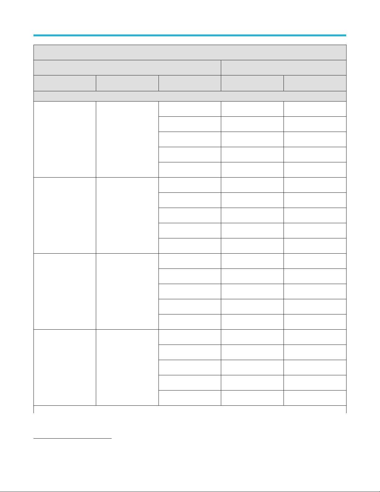
Random Noise, sample acquisition mode: MSO68B, MSO66B, MSO64B
Performance checks 1 MΩ, 12.5 GS/s
Performance verification procedures
V/div
Bandwidth
23
Models: MSO68B, MSO66B, MSO64B
Channel 2 1 mV/div 500 MHz limit
350 MHz limit
250 MHz limit
200 MHz limit
20 MHz limit
Channel 2 2 mV/div 500 MHz limit
350 MHz limit
250 MHz limit
200 MHz limit
20 MHz limit
Channel 2 5 mV/div 500 MHz limit
Test result (mV) High limit (mV)
262 uV
190 uV
153 uV
153 uV
102 uV
285 uV
195 uV
156 uV
153 uV
111 uV
311 uV
350 MHz limit
250 MHz limit
200 MHz limit
20 MHz limit
Channel 2 10 mV/div 500 MHz limit
350 MHz limit
250 MHz limit
200 MHz limit
20 MHz limit
Table continued…
23
Full = the highest bandwidth setting you can select.
223 uV
183 uV
175 uV
140 uV
370 uV
281 uV
259 uV
242 uV
226 uV
6 Series B Mixed Signal Oscilloscopes Specifications and Performance Verification 78

Random Noise, sample acquisition mode: MSO68B, MSO66B, MSO64B
Performance checks 1 MΩ, 12.5 GS/s
Performance verification procedures
V/div
Bandwidth
23
Models: MSO68B, MSO66B, MSO64B
Channel 2 20 mV/div 500 MHz limit
350 MHz limit
250 MHz limit
200 MHz limit
20 MHz limit
Channel 2 50 mV/div 500 MHz limit
350 MHz limit
250 MHz limit
200 MHz limit
20 MHz limit
Channel 2 100 mV/div 500 MHz limit
Test result (mV) High limit (mV)
536 uV
473 uV
398 uV
398 uV
398 uV
1.1 mV
896 uV
994 uV
994 uV
994 uV
2.39 mV
350 MHz limit
250 MHz limit
200 MHz limit
20 MHz limit
Channel 2 1 V/div 500 MHz limit
350 MHz limit
250 MHz limit
200 MHz limit
20 MHz limit
23
Full = the highest bandwidth setting you can select.
2.08 mV
1.99 mV
1.99 mV
1.99 mV
25.9 mV
22.3 mV
22.1 mV
21.8 mV
19.9 mV
6 Series B Mixed Signal Oscilloscopes Specifications and Performance Verification 79
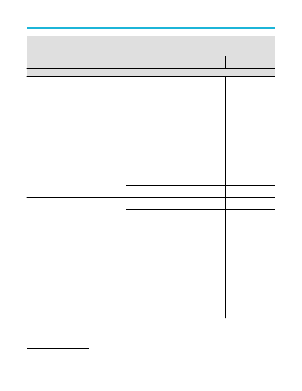
Random Noise, sample acquisition mode: MSO68B, MSO66B, MSO64B
Performance checks 50 Ω, 50 GS/s
Performance verification procedures
V/div
Bandwidth
24
Test result (mV) High limit
Models: MSO64B
Channel 3 1 mV/div 10 GHz limit 259 uV
9 GHz limit 236 uV
8 GHz limit 216 uV
7 GHz limit 197 uV
6 GHz limit 175 uV
2 mV/div 10 GHz limit 266 uV
9 GHz limit 242 uV
8 GHz limit 221 uV
7 GHz limit 199 uV
6 GHz limit 180 uV
Channel 3 5 mV/div 10 GHz limit 322 uV
10 mV/div 10 GHz limit 488 uV
Table continued…
24
Start with the highest bandwidth setting you can select.
9 GHz limit 293 uV
8 GHz limit 271 uV
7 GHz limit 247 uV
6 GHz limit 220 uV
9 GHz limit 445 uV
8 GHz limit 406 uV
7 GHz limit 370 uV
6 GHz limit 330 uV
6 Series B Mixed Signal Oscilloscopes Specifications and Performance Verification 80

Random Noise, sample acquisition mode: MSO68B, MSO66B, MSO64B
Performance checks 50 Ω, 50 GS/s
Performance verification procedures
V/div
Bandwidth
24
Test result (mV) High limit
Models: MSO64B
Channel 3 20 mV/div 10 GHz limit 850 uV
9 GHz limit 775 uV
8 GHz limit 707 uV
7 GHz limit 645 uV
6 GHz limit 581 uV
50 mV/div 10 GHz limit 1.96 mV
9 GHz limit 1.79 mV
8 GHz limit 1.63 mV
7 GHz limit 1.5 mV
6 GHz limit 1.34 mV
Channel 3 100 mV/div 10 GHz limit 5.05 mV
1 V/div 10 GHz limit 38.8 mV
24
Start with the highest bandwidth setting you can select.
9 GHz limit 4.55 mV
8 GHz limit 4.15 mV
7 GHz limit 3.79 mV
6 GHz limit 3.38 mV
9 GHz limit 35.4 mV
8 GHz limit 32.6 mV
7 GHz limit 29.7 mV
6 GHz limit 26.8 mV
6 Series B Mixed Signal Oscilloscopes Specifications and Performance Verification 81

Random Noise, sample acquisition mode: MSO68B, MSO66B, MSO64B
Performance checks 50 Ω, 25 GS/s
Performance verification procedures
V/div
Bandwidth
25
Test result (mV) High limit
Models: MSO64B
Channel 3 1 mV/div 10 GHz limit 281 uV
9 GHz limit 253 uV
8 GHz limit 223 uV
7 GHz limit 199 uV
6 GHz limit 179 uV
2 mV/div 10 GHz limit 288 uV
9 GHz limit 260 uV
8 GHz limit 224 uV
7 GHz limit 202 uV
6 GHz limit 180 uV
Channel 3 5 mV/div 10 GHz limit 374 uV
10 mV/div 10 GHz limit 600 uV
Table continued…
25
Start with the highest bandwidth setting you can select.
9 GHz limit 337 uV
8 GHz limit 293 uV
7 GHz limit 271 uV
6 GHz limit 233 uV
9 GHz limit 541 uV
8 GHz limit 482 uV
7 GHz limit 440 uV
6 GHz limit 388 uV
6 Series B Mixed Signal Oscilloscopes Specifications and Performance Verification 82

Random Noise, sample acquisition mode: MSO68B, MSO66B, MSO64B
Performance checks 50 Ω, 25 GS/s
Performance verification procedures
V/div
Bandwidth
25
Test result (mV) High limit
Models: MSO64B
Channel 3 20 mV/div 10 GHz limit 1.08 mV
9 GHz limit 976 uV
8 GHz limit 890 uV
7 GHz limit 793 uV
6 GHz limit 691 uV
50 mV/div 10 GHz limit 2.53 mV
9 GHz limit 2.3 mV
8 GHz limit 2.1 mV
7 GHz limit 1.85 mV
6 GHz limit 1.67 mV
Channel 3 100 mV/div 10 GHz limit 6.14 mV
1 V/div 10 GHz limit 49.9 mV
25
Start with the highest bandwidth setting you can select.
9 GHz limit 5.54 mV
8 GHz limit 4.88 mV
7 GHz limit 4.4 mV
6 GHz limit 3.83 mV
9 GHz limit 46.1 mV
8 GHz limit 42 mV
7 GHz limit 37 mV
6 GHz limit 33.4 mV
6 Series B Mixed Signal Oscilloscopes Specifications and Performance Verification 83

Random Noise, sample acquisition mode: MSO68B, MSO66B, MSO64B
Performance checks 50 Ω, 12.5 GS/s
Performance verification procedures
V/div
Channel 3 1 mV/div
2 mV/div
Channel 3 5 mV/div
10 mV/div
Channel 3 20 mV/div
50 mV/div
Channel 3 100 mV/div
1 V/div
Bandwidth
26
Test result (mV) High limit
Models: MSO68B, MSO66B, MSO64B
5GHz 162 uV
4GHz 142 uV
3GHz 123 uV
5GHz 168 uV
4GHz 148 uV
3GHz 127 uV
5GHz 233 uV
4GHz 203 uV
3GHz 173 uV
5GHz 388 uV
4GHz 334 uV
3GHz 281 uV
5GHz 715 uV
4GHz 609 uV
3GHz 518 uV
5GHz 1.71 mV
4GHz 1.47 mV
3GHz 1.25 mV
5GHz 3.92 mV
4GHz 3.38 mV
3GHz 2.84 mV
5GHz 34.2 mV
4GHz 29.4 mV
3GHz 25 mV
26
Start with the highest bandwidth setting you can select.
6 Series B Mixed Signal Oscilloscopes Specifications and Performance Verification 84

Random Noise, sample acquisition mode: MSO68B, MSO66B, MSO64B
Performance checks 1 MΩ, 25 GS/s
Performance verification procedures
V/div
Bandwidth
27
Models: MSO64B
Channel 3 1 mV/div 500 MHz limit
350 MHz limit
250 MHz limit
200 MHz limit
20 MHz limit
Channel 3 2 mV/div 500 MHz limit
350 MHz limit
250 MHz limit
200 MHz limit
20 MHz limit
Channel 3 5 mV/div 500 MHz limit
Test result (mV) High limit (mV)
262 uV
190 uV
153 uV
153 uV
102 uV
285 uV
195 uV
156 uV
153 uV
111 uV
311 uV
350 MHz limit
250 MHz limit
200 MHz limit
20 MHz limit
Channel 3 10 mV/div 500 MHz limit
350 MHz limit
250 MHz limit
200 MHz limit
20 MHz limit
Table continued…
27
Full = the highest bandwidth setting you can select.
223 uV
183 uV
175 uV
140 uV
370 uV
281 uV
259 uV
242 uV
226 uV
6 Series B Mixed Signal Oscilloscopes Specifications and Performance Verification 85

Random Noise, sample acquisition mode: MSO68B, MSO66B, MSO64B
Performance checks 1 MΩ, 25 GS/s
Performance verification procedures
V/div
Bandwidth
27
Models: MSO64B
Channel 3 20 mV/div 500 MHz limit
350 MHz limit
250 MHz limit
200 MHz limit
20 MHz limit
Channel 3 50 mV/div 500 MHz limit
350 MHz limit
250 MHz limit
200 MHz limit
20 MHz limit
Channel 3 100 mV/div 500 MHz limit
Test result (mV) High limit (mV)
536 uV
473 uV
398 uV
398 uV
398 uV
1.1 mV
896 uV
994 uV
994 uV
994 uV
2.39 mV
350 MHz limit
250 MHz limit
200 MHz limit
20 MHz limit
Channel 3 1 V/div 500 MHz limit
350 MHz limit
250 MHz limit
200 MHz limit
20 MHz limit
27
Full = the highest bandwidth setting you can select.
2.08 mV
1.99 mV
1.99 mV
1.99 mV
25.9 mV
22.3 mV
22.1 mV
21.8 mV
19.9 mV
6 Series B Mixed Signal Oscilloscopes Specifications and Performance Verification 86

Random Noise, sample acquisition mode: MSO68B, MSO66B, MSO64B
Performance checks 1 MΩ, 12.5 GS/s
Performance verification procedures
V/div
Bandwidth
28
Models: MSO68B, MSO66B, MSO64B
Channel 3 1 mV/div 500 MHz limit
350 MHz limit
250 MHz limit
200 MHz limit
20 MHz limit
Channel 3 2 mV/div 500 MHz limit
350 MHz limit
250 MHz limit
200 MHz limit
20 MHz limit
Channel 3 5 mV/div 500 MHz limit
Test result (mV) High limit (mV)
262 uV
190 uV
153 uV
153 uV
102 uV
285 uV
195 uV
156 uV
153 uV
111 uV
311 uV
350 MHz limit
250 MHz limit
200 MHz limit
20 MHz limit
Channel 3 10 mV/div 500 MHz limit
350 MHz limit
250 MHz limit
200 MHz limit
20 MHz limit
Table continued…
28
Full = the highest bandwidth setting you can select.
223 uV
183 uV
175 uV
140 uV
370 uV
281 uV
259 uV
242 uV
226 uV
6 Series B Mixed Signal Oscilloscopes Specifications and Performance Verification 87

Random Noise, sample acquisition mode: MSO68B, MSO66B, MSO64B
Performance checks 1 MΩ, 12.5 GS/s
Performance verification procedures
V/div
Bandwidth
28
Models: MSO68B, MSO66B, MSO64B
Channel 3 20 mV/div 500 MHz limit
350 MHz limit
250 MHz limit
200 MHz limit
20 MHz limit
Channel 3 50 mV/div 500 MHz limit
350 MHz limit
250 MHz limit
200 MHz limit
20 MHz limit
Channel 3 100 mV/div 500 MHz limit
Test result (mV) High limit (mV)
536 uV
473 uV
398 uV
398 uV
398 uV
1.1 mV
896 uV
994 uV
994 uV
994 uV
2.39 mV
350 MHz limit
250 MHz limit
200 MHz limit
20 MHz limit
Channel 3 1 V/div 500 MHz limit
350 MHz limit
250 MHz limit
200 MHz limit
20 MHz limit
28
Full = the highest bandwidth setting you can select.
2.08 mV
1.99 mV
1.99 mV
1.99 mV
25.9 mV
22.3 mV
22.1 mV
21.8 mV
19.9 mV
6 Series B Mixed Signal Oscilloscopes Specifications and Performance Verification 88

Random Noise, sample acquisition mode: MSO68B, MSO66B, MSO64B
Performance checks 50 Ω, 50 GS/s
Performance verification procedures
V/div
Bandwidth
29
Test result (mV) High limit
Models: MSO66B
Channel 4 1 mV/div 10 GHz limit 259 uV
9 GHz limit 236 uV
8 GHz limit 216 uV
7 GHz limit 197 uV
6 GHz limit 175 uV
2 mV/div 10 GHz limit 266 uV
9 GHz limit 242 uV
8 GHz limit 221 uV
7 GHz limit 199 uV
6 GHz limit 180 uV
Channel 4 5 mV/div 10 GHz limit 322 uV
10 mV/div 10 GHz limit 488 uV
Table continued…
29
Start with the highest bandwidth setting you can select.
9 GHz limit 293 uV
8 GHz limit 271 uV
7 GHz limit 247 uV
6 GHz limit 220 uV
9 GHz limit 445 uV
8 GHz limit 406 uV
7 GHz limit 370 uV
6 GHz limit 330 uV
6 Series B Mixed Signal Oscilloscopes Specifications and Performance Verification 89

Random Noise, sample acquisition mode: MSO68B, MSO66B, MSO64B
Performance checks 50 Ω, 50 GS/s
Performance verification procedures
V/div
Bandwidth
29
Test result (mV) High limit
Models: MSO66B
Channel 4 20 mV/div 10 GHz limit 850 uV
9 GHz limit 775 uV
8 GHz limit 707 uV
7 GHz limit 645 uV
6 GHz limit 581 uV
50 mV/div 10 GHz limit 1.96 mV
9 GHz limit 1.79 mV
8 GHz limit 1.63 mV
7 GHz limit 1.5 mV
6 GHz limit 1.34 mV
Channel 4 100 mV/div 10 GHz limit 5.05 mV
1 V/div 10 GHz limit 38.8 mV
29
Start with the highest bandwidth setting you can select.
9 GHz limit 4.55 mV
8 GHz limit 4.15 mV
7 GHz limit 3.79 mV
6 GHz limit 3.38 mV
9 GHz limit 35.4 mV
8 GHz limit 32.6 mV
7 GHz limit 29.7 mV
6 GHz limit 26.8 mV
6 Series B Mixed Signal Oscilloscopes Specifications and Performance Verification 90

Random Noise, sample acquisition mode: MSO68B, MSO66B, MSO64B
Performance checks 50 Ω, 25 GS/s
Performance verification procedures
V/div
Bandwidth
30
Test result (mV) High limit
Models: MSO66B, MSO64B
Channel 4 1 mV/div 10 GHz limit 281 uV
9 GHz limit 253 uV
8 GHz limit 223 uV
7 GHz limit 199 uV
6 GHz limit 179 uV
2 mV/div 10 GHz limit 288 uV
9 GHz limit 260 uV
8 GHz limit 224 uV
7 GHz limit 202 uV
6 GHz limit 180 uV
Channel 4 5 mV/div 10 GHz limit 374 uV
10 mV/div 10 GHz limit 600 uV
Table continued…
30
Start with the highest bandwidth setting you can select.
9 GHz limit 337 uV
8 GHz limit 293 uV
7 GHz limit 271 uV
6 GHz limit 233 uV
9 GHz limit 541 uV
8 GHz limit 482 uV
7 GHz limit 440 uV
6 GHz limit 388 uV
6 Series B Mixed Signal Oscilloscopes Specifications and Performance Verification 91

Random Noise, sample acquisition mode: MSO68B, MSO66B, MSO64B
Performance checks 50 Ω, 25 GS/s
Performance verification procedures
V/div
Bandwidth
30
Test result (mV) High limit
Models: MSO66B, MSO64B
Channel 4 20 mV/div 10 GHz limit 1.08 mV
9 GHz limit 976 uV
8 GHz limit 890 uV
7 GHz limit 793 uV
6 GHz limit 691 uV
50 mV/div 10 GHz limit 2.53 mV
9 GHz limit 2.3 mV
8 GHz limit 2.1 mV
7 GHz limit 1.85 mV
6 GHz limit 1.67 mV
Channel 4 100 mV/div 10 GHz limit 6.14 mV
1 V/div 10 GHz limit 49.9 mV
30
Start with the highest bandwidth setting you can select.
9 GHz limit 5.54 mV
8 GHz limit 4.88 mV
7 GHz limit 4.4 mV
6 GHz limit 3.83 mV
9 GHz limit 46.1 mV
8 GHz limit 42 mV
7 GHz limit 37 mV
6 GHz limit 33.4 mV
6 Series B Mixed Signal Oscilloscopes Specifications and Performance Verification 92
Random Noise, sample acquisition mode: MSO68B, MSO66B, MSO64B
Performance checks 50 Ω, 12.5 GS/s
Performance verification procedures
V/div
Channel 4 1 mV/div
2 mV/div
Channel 4 5 mV/div
10 mV/div
Channel 4 20 mV/div
50 mV/div
Channel 4 100 mV/div
1 V/div
Bandwidth
31
Test result (mV) High limit
Models: MSO68B, MSO66B, MSO64B
5GHz 162 uV
4GHz 142 uV
3GHz 123 uV
5GHz 168 uV
4GHz 148 uV
3GHz 127 uV
5GHz 233 uV
4GHz 203 uV
3GHz 173 uV
5GHz 388 uV
4GHz 334 uV
3GHz 281 uV
5GHz 715 uV
4GHz 609 uV
3GHz 518 uV
5GHz 1.71 mV
4GHz 1.47 mV
3GHz 1.25 mV
5GHz 3.92 mV
4GHz 3.38 mV
3GHz 2.84 mV
5GHz 34.2 mV
4GHz 29.4 mV
3GHz 25 mV
31
Start with the highest bandwidth setting you can select.
6 Series B Mixed Signal Oscilloscopes Specifications and Performance Verification 93

Random Noise, sample acquisition mode: MSO68B, MSO66B, MSO64B
Performance checks 1 MΩ, 25 GS/s
Performance verification procedures
V/div
Bandwidth
32
Models: MSO66B, MSO64B
Channel 4 1 mV/div 500 MHz limit
350 MHz limit
250 MHz limit
200 MHz limit
20 MHz limit
Channel 4 2 mV/div 500 MHz limit
350 MHz limit
250 MHz limit
200 MHz limit
20 MHz limit
Channel 4 5 mV/div 500 MHz limit
Test result (mV) High limit (mV)
262 uV
190 uV
153 uV
153 uV
102 uV
285 uV
195 uV
156 uV
153 uV
111 uV
311 uV
350 MHz limit
250 MHz limit
200 MHz limit
20 MHz limit
Channel 4 10 mV/div 500 MHz limit
350 MHz limit
250 MHz limit
200 MHz limit
20 MHz limit
Table continued…
32
Full = the highest bandwidth setting you can select.
223 uV
183 uV
175 uV
140 uV
370 uV
281 uV
259 uV
242 uV
226 uV
6 Series B Mixed Signal Oscilloscopes Specifications and Performance Verification 94
Random Noise, sample acquisition mode: MSO68B, MSO66B, MSO64B
Performance checks 1 MΩ, 25 GS/s
Performance verification procedures
V/div
Bandwidth
32
Models: MSO66B, MSO64B
Channel 4 20 mV/div 500 MHz limit
350 MHz limit
250 MHz limit
200 MHz limit
20 MHz limit
Channel 4 50 mV/div 500 MHz limit
350 MHz limit
250 MHz limit
200 MHz limit
20 MHz limit
Channel 4 100 mV/div 500 MHz limit
Test result (mV) High limit (mV)
536 uV
473 uV
398 uV
398 uV
398 uV
1.1 mV
896 uV
994 uV
994 uV
994 uV
2.39 mV
350 MHz limit
250 MHz limit
200 MHz limit
20 MHz limit
Channel 4 1 V/div 500 MHz limit
350 MHz limit
250 MHz limit
200 MHz limit
20 MHz limit
32
Full = the highest bandwidth setting you can select.
2.08 mV
1.99 mV
1.99 mV
1.99 mV
25.9 mV
22.3 mV
22.1 mV
21.8 mV
19.9 mV
6 Series B Mixed Signal Oscilloscopes Specifications and Performance Verification 95

Random Noise, sample acquisition mode: MSO68B, MSO66B, MSO64B
Performance checks 1 MΩ, 12.5 GS/s
Performance verification procedures
V/div
Bandwidth
33
Models: MSO68B, MSO66B, MSO64B
Channel 4 1 mV/div 500 MHz limit
350 MHz limit
250 MHz limit
200 MHz limit
20 MHz limit
Channel 4 2 mV/div 500 MHz limit
350 MHz limit
250 MHz limit
200 MHz limit
20 MHz limit
Channel 4 5 mV/div 500 MHz limit
Test result (mV) High limit (mV)
262 uV
190 uV
153 uV
153 uV
102 uV
285 uV
195 uV
156 uV
153 uV
111 uV
311 uV
350 MHz limit
250 MHz limit
200 MHz limit
20 MHz limit
Channel 4 10 mV/div 500 MHz limit
350 MHz limit
250 MHz limit
200 MHz limit
20 MHz limit
Table continued…
33
Full = the highest bandwidth setting you can select.
223 uV
183 uV
175 uV
140 uV
370 uV
281 uV
259 uV
242 uV
226 uV
6 Series B Mixed Signal Oscilloscopes Specifications and Performance Verification 96

Random Noise, sample acquisition mode: MSO68B, MSO66B, MSO64B
Performance checks 1 MΩ, 12.5 GS/s
Performance verification procedures
V/div
Bandwidth
33
Models: MSO68B, MSO66B, MSO64B
Channel 4 20 mV/div 500 MHz limit
350 MHz limit
250 MHz limit
200 MHz limit
20 MHz limit
Channel 4 50 mV/div 500 MHz limit
350 MHz limit
250 MHz limit
200 MHz limit
20 MHz limit
Channel 4 100 mV/div 500 MHz limit
Test result (mV) High limit (mV)
536 uV
473 uV
398 uV
398 uV
398 uV
1.1 mV
896 uV
994 uV
994 uV
994 uV
2.39 mV
350 MHz limit
250 MHz limit
200 MHz limit
20 MHz limit
Channel 4 1 V/div 500 MHz limit
350 MHz limit
250 MHz limit
200 MHz limit
20 MHz limit
33
Full = the highest bandwidth setting you can select.
2.08 mV
1.99 mV
1.99 mV
1.99 mV
25.9 mV
22.3 mV
22.1 mV
21.8 mV
19.9 mV
6 Series B Mixed Signal Oscilloscopes Specifications and Performance Verification 97
Random Noise, sample acquisition mode: MSO68B, MSO66B, MSO64B
Performance checks 50 Ω, 50 GS/s
Performance verification procedures
V/div
Bandwidth
34
Test result (mV) High limit
Models: MSO68B
Channel 5 1 mV/div 10 GHz limit 259 uV
9 GHz limit 236 uV
8 GHz limit 216 uV
7 GHz limit 197 uV
6 GHz limit 175 uV
2 mV/div 10 GHz limit 266 uV
9 GHz limit 242 uV
8 GHz limit 221 uV
7 GHz limit 199 uV
6 GHz limit 180 uV
Channel 5 5 mV/div 10 GHz limit 322 uV
10 mV/div 10 GHz limit 488 uV
Table continued…
34
Start with the highest bandwidth setting you can select.
9 GHz limit 293 uV
8 GHz limit 271 uV
7 GHz limit 247 uV
6 GHz limit 220 uV
9 GHz limit 445 uV
8 GHz limit 406 uV
7 GHz limit 370 uV
6 GHz limit 330 uV
6 Series B Mixed Signal Oscilloscopes Specifications and Performance Verification 98

Random Noise, sample acquisition mode: MSO68B, MSO66B, MSO64B
Performance checks 50 Ω, 50 GS/s
Performance verification procedures
V/div
Bandwidth
34
Test result (mV) High limit
Models: MSO68B
Channel 5 20 mV/div 10 GHz limit 850 uV
9 GHz limit 775 uV
8 GHz limit 707 uV
7 GHz limit 645 uV
6 GHz limit 581 uV
50 mV/div 10 GHz limit 1.96 mV
9 GHz limit 1.79 mV
8 GHz limit 1.63 mV
7 GHz limit 1.5 mV
6 GHz limit 1.34 mV
Channel 5 100 mV/div 10 GHz limit 5.05 mV
1 V/div 10 GHz limit 38.8 mV
34
Start with the highest bandwidth setting you can select.
9 GHz limit 4.55 mV
8 GHz limit 4.15 mV
7 GHz limit 3.79 mV
6 GHz limit 3.38 mV
9 GHz limit 35.4 mV
8 GHz limit 32.6 mV
7 GHz limit 29.7 mV
6 GHz limit 26.8 mV
6 Series B Mixed Signal Oscilloscopes Specifications and Performance Verification 99

Random Noise, sample acquisition mode: MSO68B, MSO66B, MSO64B
Performance checks 50 Ω, 25 GS/s
Performance verification procedures
V/div
Bandwidth
35
Test result (mV) High limit
Models: MSO68B, MSO66B
Channel 5 1 mV/div 10 GHz limit 281 uV
9 GHz limit 253 uV
8 GHz limit 223 uV
7 GHz limit 199 uV
6 GHz limit 179 uV
2 mV/div 10 GHz limit 288 uV
9 GHz limit 260 uV
8 GHz limit 224 uV
7 GHz limit 202 uV
6 GHz limit 180 uV
Channel 5 5 mV/div 10 GHz limit 374 uV
10 mV/div 10 GHz limit 600 uV
Table continued…
35
Start with the highest bandwidth setting you can select.
9 GHz limit 337 uV
8 GHz limit 293 uV
7 GHz limit 271 uV
6 GHz limit 233 uV
9 GHz limit 541 uV
8 GHz limit 482 uV
7 GHz limit 440 uV
6 GHz limit 388 uV
6 Series B Mixed Signal Oscilloscopes Specifications and Performance Verification 100
 Loading...