

Page 1

6 Series MSO
MSO64
Installation and Safety Manual
6 シリーズ MSO
MSO64 型
設置と安全性に関するマニュアル
6 系列 MSO
MSO64
安装和安全手册
*P071357900*
071-3579-00
Page 2

Page 3

6 Series MSO
MSO64
Installation and Safety Manual
Supports 6 Series MSO Product Firmware V1.8 and above
www.tek.com
071-3579-00
Page 4

Copyright © Tektronix. All rights reserved. Licensed software products are owned by Tektronix or its subsidiaries or suppliers, and are
protected by national copyright laws and international treaty provisions. Tektronix products are covered by U.S. and foreign patents, issued
and pending. Information in this publication supersedes that in all previously published material. Specifications and price change privileges
reserved.
TEKTRONIX and TEK are registered trademarks of Tektronix, Inc.
TekSecure is a trademark of Tektronix, Inc.
FlexChannel, TekVPI, FastAcq, and e*Scope are registered trademarks of Tektronix, Inc.
Contacting Tektronix
Tektronix, Inc.
14150 SW Karl Braun Drive
P.O. Box 500
Beaverton, OR 97077
USA
For product information, sales, service, and technical support:
■
In North America, call 1-800-833-9200.
■
Worldwide, visit www.tek.com to find contacts in your area.
Page 5

Warranty
Tektronix warrants that this product will be free from defects in materials and workmanship for a period of three (3) years from the date of
shipment. If any such product proves defective during this warranty period, Tektronix, at its option, either will repair the defective product
without charge for parts and labor, or will provide a replacement in exchange for the defective product. Parts, modules and replacement
products used by Tektronix for warranty work may be new or reconditioned to like new performance. All replaced parts, modules and
products become the property of Tektronix.
In order to obtain service under this warranty, Customer must notify Tektronix of the defect before the expiration of the warranty period and
make suitable arrangements for the performance of service. Customer shall be responsible for packaging and shipping the defective
product to the service center designated by Tektronix, with shipping charges prepaid. Tektronix shall pay for the return of the product to
Customer if the shipment is to a location within the country in which the Tektronix service center is located. Customer shall be responsible
for paying all shipping charges, duties, taxes, and any other charges for products returned to any other locations.
This warranty shall not apply to any defect, failure or damage caused by improper use or improper or inadequate maintenance and care.
Tektronix shall not be obligated to furnish service under this warranty a) to repair damage resulting from attempts by personnel other than
Tektronix representatives to install, repair or service the product; b) to repair damage resulting from improper use or connection to
incompatible equipment; c) to repair any damage or malfunction caused by the use of non-Tektronix supplies; or d) to service a product
that has been modified or integrated with other products when the effect of such modification or integration increases the time or difficulty
of servicing the product.
THIS WARRANTY IS GIVEN BY TEKTRONIX WITH RESPECT TO THE PRODUCT IN LIEU OF ANY OTHER WARRANTIES, EXPRESS
OR IMPLIED. TEKTRONIX AND ITS VENDORS DISCLAIM ANY IMPLIED WARRANTIES OF MERCHANTABILITY OR FITNESS FOR A
PARTICULAR PURPOSE. TEKTRONIX' RESPONSIBILITY TO REPAIR OR REPLACE DEFECTIVE PRODUCTS IS THE SOLE AND
EXCLUSIVE REMEDY PROVIDED TO THE CUSTOMER FOR BREACH OF THIS WARRANTY. TEKTRONIX AND ITS VENDORS WILL
NOT BE LIABLE FOR ANY INDIRECT, SPECIAL, INCIDENTAL, OR CONSEQUENTIAL DAMAGES IRRESPECTIVE OF WHETHER
TEKTRONIX OR THE VENDOR HAS ADVANCE NOTICE OF THE POSSIBILITY OF SUCH DAMAGES.
[W4 – 15AUG04]
Page 6

Page 7

Table of Contents
Important safety information ................................................................................................................................ iii
General safety summary ................................................................................................................................ iii
Service safety summary ................................................................................................................................. v
Terms in the manual ...................................................................................................................................... vi
Terms on the product .................................................................................................................................... vi
Symbols on the product ................................................................................................................................. vi
Preface ............................................................................................................................................................... vii
Key features .................................................................................................................................................. vii
Related documents ....................................................................................................................................... vii
Installing your instrument
Check shipped accessories ........................................................................................................................... 1
Safely rotate the handle ................................................................................................................................. 1
Operating requirements ................................................................................................................................. 2
Input signal requirements ............................................................................................................................... 3
Secure (lock) the oscilloscope ....................................................................................................................... 3
Powering the oscilloscope .............................................................................................................................. 4
Check that oscilloscope passes power-on self tests ...................................................................................... 5
Connecting Probes ......................................................................................................................................... 5
Rackmount information .................................................................................................................................. 6
Getting acquainted with your instrument
Front panel controls and connectors .............................................................................................................. 7
Rear panel connections ............................................................................................................................... 14
The user interface screen ............................................................................................................................ 15
The user interface elements ......................................................................................................................... 16
Badges ......................................................................................................................................................... 20
Configuration menus .................................................................................................................................... 26
The Zoom user interface elements .............................................................................................................. 28
Using the touch screen interface for common tasks .................................................................................... 29
Configure the instrument
Set the time zone and clock readout format ................................................................................................. 31
Download and install the latest firmware ...................................................................................................... 31
Run Signal Path Compensation (SPC) ........................................................................................................ 32
MSO64 Installation and Safety Manual
i
Page 8

Table of Contents
Compensate the TPP0500B or TPP1000 probes ........................................................................................ 32
Connect to a network (LAN) ......................................................................................................................... 34
Operating basics
Add a channel waveform to the display ....................................................................................................... 35
Configure channel or waveform settings ...................................................................................................... 36
Quickly display a waveform (Autoset) .......................................................................................................... 37
How to trigger on a signal ............................................................................................................................ 38
Set the acquisition mode .............................................................................................................................. 39
Set Horizontal parameters ........................................................................................................................... 40
Add a math, reference, or bus waveform ..................................................................................................... 41
Add a measurement ..................................................................................................................................... 42
Configure a measurement ............................................................................................................................ 44
Add a plot of a measurement ....................................................................................................................... 45
Add a Search ............................................................................................................................................... 47
Delete a Measurement or Search badge ..................................................................................................... 48
Change waveform view settings .................................................................................................................. 49
Display and configure cursors ...................................................................................................................... 49
Remote access from a Web browser ........................................................................................................... 51
Connect the oscilloscope to a PC using a USB cable .................................................................................. 52
Cleaning the instrument
Cleaning ....................................................................................................................................................... 53
EMC, safety and environmental compliance
Compliance Information ............................................................................................................................... 55
EMC compliance .................................................................................................................................... 55
Safety compliance .................................................................................................................................. 56
Environmental compliance ..................................................................................................................... 57
ii MSO64 Installation and Safety Manual
Page 9

Important safety information
Safety information provides warnings and cautions that help you operate the instrument safely and keep the instrument in a safe
working condition.
This manual contains information and warnings that must be followed by the user for safe operation and to keep the product in a
safe condition.
To safely perform service on this product, see the Service safety summary that follows the General safety summary.
General safety summary
Use the product only as specified. Review the following safety precautions to avoid injury and prevent damage to this product or
any products connected to it. Carefully read all instructions. Retain these instructions for future reference.
This product shall be used in accordance with local and national codes.
For correct and safe operation of the product, it is essential that you follow generally accepted safety procedures in addition to
the safety precautions specified in this manual.
The product is designed to be used by trained personnel only.
Only qualified personnel who are aware of the hazards involved should remove the cover for repair, maintenance, or adjustment.
Before use, always check the product with a known source to be sure it is operating correctly.
This product is not intended for detection of hazardous voltages.
Use personal protective equipment to prevent shock and arc blast injury where hazardous live conductors are exposed.
While using this product, you may need to access other parts of a larger system. Read the safety sections of the other
component manuals for warnings and cautions related to operating the system.
When incorporating this equipment into a system, the safety of that system is the responsibility of the assembler of the system.
To avoid fire or personal injury
Use proper power cord. Use only the power cord specified for this product and certified for the country of use. Do not use the
provided power cord for other products.
Ground the product. This product is grounded through the grounding conductor of the power cord. To avoid electric shock, the
grounding conductor must be connected to earth ground. Before making connections to the input or output terminals of the
product, ensure that the product is properly grounded. Do not disable the power cord grounding connection.
Power disconnect. The power cord disconnects the product from the power source. See instructions for the location. Do not
position the equipment so that it is difficult to operate the power cord; it must remain accessible to the user at all times to allow for
quick disconnection if needed.
Connect and disconnect properly. Do not connect or disconnect probes or test leads while they are connected to a voltage
source. Use only insulated voltage probes, test leads, and adapters supplied with the product, or indicated by Tektronix to be
suitable for the product.
Observe all terminal ratings. To avoid fire or shock hazard, observe all rating and markings on the product. Consult the product
manual for further ratings information before making connections to the product. Do not exceed the Measurement Category
(CAT) rating and voltage or current rating of the lowest rated individual component of a product, probe, or accessory. Use caution
when using 1:1 test leads because the probe tip voltage is directly transmitted to the product.
Do not apply a potential to any terminal, including the common terminal, that exceeds the maximum rating of that terminal.
Do not float the common terminal above the rated voltage for that terminal.
MSO64 Installation and Safety Manual
iii
Page 10

Important safety information
The measuring terminals on this product are not rated for connection to mains or Category II, III, or IV circuits.
Do not operate without covers. Do not operate this product with covers or panels removed, or with the case open. Hazardous
voltage exposure is possible.
Avoid exposed circuitry. Do not touch exposed connections and components when power is present.
Do not operate with suspected failures. If you suspect that there is damage to this product, have it inspected by qualified
service personnel.
Disable the product if it is damaged. Do not use the product if it is damaged or operates incorrectly. If in doubt about safety of the
product, turn it off and disconnect the power cord. Clearly mark the product to prevent its further operation.
Before use, inspect voltage probes, test leads, and accessories for mechanical damage and replace when damaged. Do not use
probes or test leads if they are damaged, if there is exposed metal, or if a wear indicator shows.
Examine the exterior of the product before you use it. Look for cracks or missing pieces.
Use only specified replacement parts.
Do not operate in wet/damp conditions. Be aware that condensation may occur if a unit is moved from a cold to a warm
environment.
Do not operate in an explosive atmosphere.
Keep product surfaces clean and dry. Remove the input signals before you clean the product.
Provide proper ventilation. Refer to the installation instructions in the manual for details on installing the product so it has
proper ventilation.
Slots and openings are provided for ventilation and should never be covered or otherwise obstructed. Do not push objects into
any of the openings.
Provide a safe working environment. Always place the product in a location convenient for viewing the display and indicators.
Avoid improper or prolonged use of keyboards, pointers, and button pads. Improper or prolonged keyboard or pointer use may
result in serious injury.
Be sure your work area meets applicable ergonomic standards. Consult with an ergonomics professional to avoid stress injuries.
Use care when lifting and carrying the product. This product is provided with a handle for lifting and carrying.
Use only the Tektronix rackmount hardware specified for this product.
Probes and test leads
Before connecting probes or test leads, connect the power cord from the power connector to a properly grounded power outlet.
Keep fingers behind the protective barrier, protective finger guard, or tactile indicator on the probes.
Remove all probes, test leads and accessories that are not in use.
Use only correct Measurement Category (CAT), voltage, temperature, altitude, and amperage rated probes, test leads, and
adapters for any measurement.
iv MSO64 Installation and Safety Manual
Page 11
Important safety information
Beware of high voltages. Understand the voltage ratings for the probe you are using and do not exceed those ratings. Two
ratings are important to know and understand:
■
The maximum measurement voltage from the probe tip to the probe reference lead
■
The maximum floating voltage from the probe reference lead to earth ground
These two voltage ratings depend on the probe and your application. Refer to the Specifications section of the manual for more
information.
WARNING. To prevent electrical shock, do not exceed the maximum measurement or maximum floating voltage for the
oscilloscope input BNC connector, probe tip, or probe reference lead.
Connect and disconnect properly. Connect the probe output to the measurement product before connecting the probe to the
circuit under test. Connect the probe reference lead to the circuit under test before connecting the probe input. Disconnect the
probe input and the probe reference lead from the circuit under test before disconnecting the probe from the measurement
product.
Connect and disconnect properly. De-energize the circuit under test before connecting or disconnecting the current probe.
Connect the probe reference lead to earth ground only.
Do not connect a current probe to any wire that carries voltages or frequencies above the current probe voltage rating.
Inspect the probe and accessories. Before each use, inspect probe and accessories for damage (cuts, tears, or defects in the
probe body, accessories, or cable jacket). Do not use if damaged.
Service safety summary
The Service safety summary section contains additional information required to safely perform service on the product. Only
qualified personnel should perform service procedures. Read this Service safety summary and the General safety summary
before performing any service procedures.
To avoid electric shock. Do not touch exposed connections.
Do not service alone. Do not perform internal service or adjustments of this product unless another person capable of rendering
first aid and resuscitation is present.
Disconnect power. To avoid electric shock, switch off the product power and disconnect the power cord from the mains power
before removing any covers or panels, or opening the case for servicing.
Use care when servicing with power on. Dangerous voltages or currents may exist in this product. Disconnect power, remove
battery (if applicable), and disconnect test leads before removing protective panels, soldering, or replacing components.
Verify safety after repair. Always recheck ground continuity and mains dielectric strength after performing a repair.
MSO64 Installation and Safety Manual v
Page 12
Important safety information
Terms in the manual
These terms may appear in this manual:
WARNING. Warning statements identify conditions or practices that could result in injury or loss of life.
CAUTION. Caution statements identify conditions or practices that could result in damage to this product or other property.
Terms on the product
These terms may appear on the product:
■
DANGER indicates an injury hazard immediately accessible as you read the marking.
■
WARNING indicates an injury hazard not immediately accessible as you read the marking.
■
CAUTION indicates a hazard to property including the product.
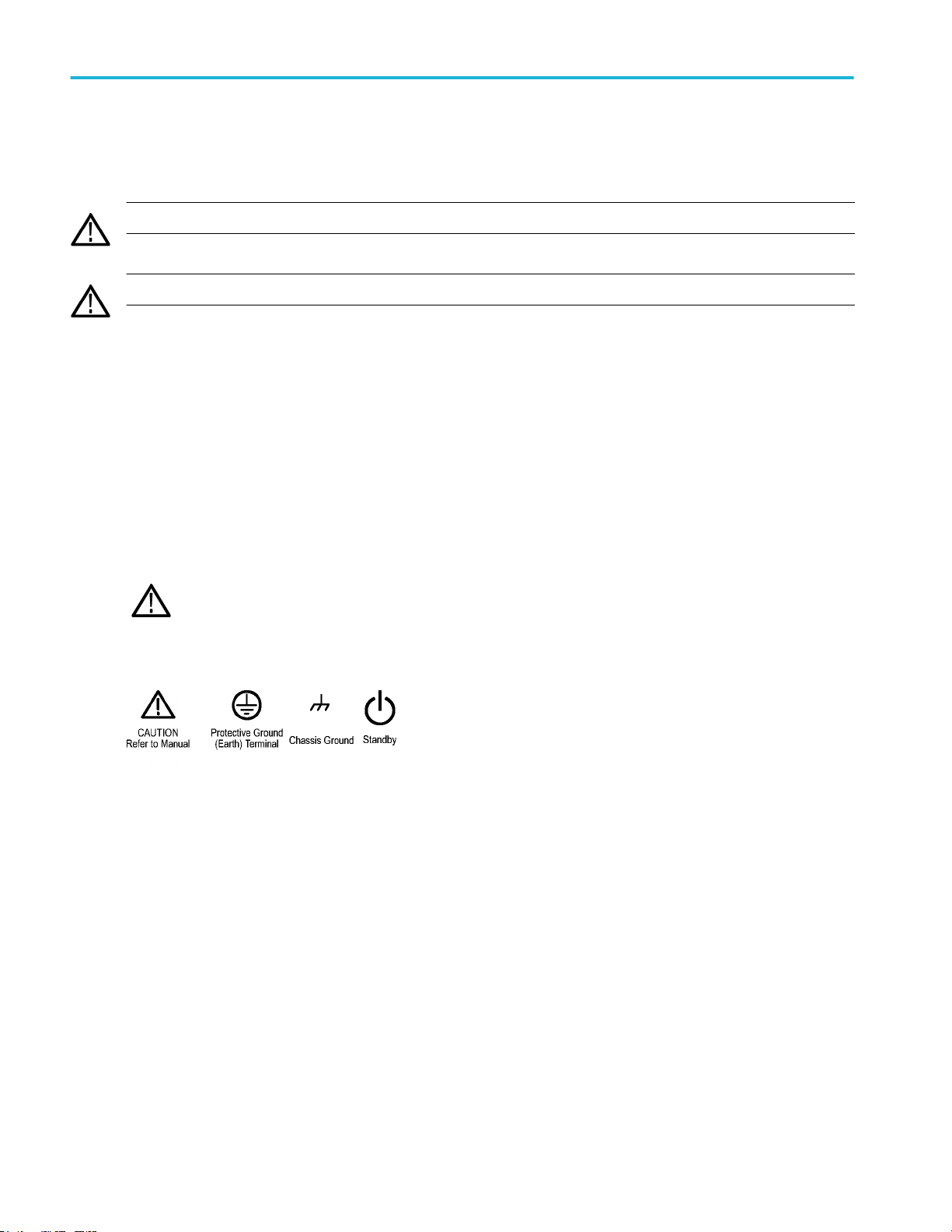
Symbols on the product
When this symbol is marked on the product, be sure to consult the manual to find out the nature of the potential
hazards and any actions which have to be taken to avoid them. (This symbol may also be used to refer the user to
ratings in the manual.)
The following symbols may appear on the product:
vi MSO64 Installation and Safety Manual
Page 13

Preface
This manual provides product safety and compliance information, describes how to connect and power on the oscilloscope, and
introduces the instrument features, controls and basic operations. See the product Help file for more detailed information.
Key features
Welcome to the 6 Series MSO. The 6 Series MSO Oscilloscopes include FlexChannel® inputs, enabling you to efficiently and
cost-effectively perform mixed signal debugging on virtually any design.
■
Bandwidths from 1 GHz to 8 GHz
■
4 channels with FlexChannel® inputs
■
FlexChannel inputs are compatible with TekVPI® probes
■
Large 15.6” HD (1920 x 1080 pixel) capacitive touch-screen display
■
User interface designed to optimize touch screen use and quickly access key settings
■
Stacked mode places each channel or waveform in its own horizontal 'slice' on the screen, allowing for cleaner signal
viewing and measuring
■
Maximum 25 GS/s sample rate
■
62.5 M points record length on all channels (optional 125 M and 250 M record lengths available)
■
30,000 waveforms/second maximum waveform capture rate
■
No set limit on the number of math, reference, and bus waveforms you can display (the number of waveforms depends on
available system memory)
■
Integrated optional features include a 50 MHz arbitrary function generator (AFG), and a DVM and trigger frequency counter
■
Optional serial triggering features enable you to isolate protocol-level events of interest in common aerospace, audio,
automotive, computer, and embedded serial buses. See the Serial bus and trigger options topic in the instrument embedded
Help, or the 6 Series MSO Serial Triggering and Analysis Applications Datasheet (Tektronix part number 48W-61353-x) for
more information
Related documents
Use the related documents for more information on instrument functions, how to remotely program or operate the instrument,
understand theory of operation, replace suspected modules, and do other tasks.
6 Series MSO documents
To learn about Use this document
How to use instrument
functions
How to remotely control the
instrument
5 Series and 6 Series MSO Help (Tektronix part number 077-1303-xx; Printable version of the
instrument Help; available at www.tek.com/downloads)
6 Series MSO Installation and Safety Manual (this document, Tektronix part number 071-3579xx); standard accessory with the instrument. Single document with English, Japanese, and
Simplified Chinese languages. A Russian language version is available to download from the
Tektronix web site (Tektronix part number 077-1432-xx)
5 Series and 6 Series MSO Programmer Manual (Tektronix part number 077-1305-xx; available
at www.tek.com/downloads)
MSO64 Installation and Safety Manual vii
Page 14

Preface
To learn about Use this document
Instrument specifications and
procedures to verify the
instrument meets
specifications
Instrument theory of operation,
troubleshooting, disassembly,
and replaceable parts
Installing the instrument in a
rack
Using the TLP058 Logic Probe TLP058 FlexChannel® Logic Probe Instructions (Tektronix part number 071-3515-xx; available
6 Series MSO Specifications and Performance Verification Technical Reference (Tektronix part
number 077-1461-xx; available at www.tek.com/downloads)
6 Series MSO Service Manual (Tektronix part number 077-1462-xx; available at www.tek.com/
downloads)
RM5 Rack Mount Kit Instructions (Tektronix part number 071-3523-xx; available at
www.tek.com/downloads)
at www.tek.com/downloads)
viii MSO64 Installation and Safety Manual
Page 15
Installing your instrument
Check shipped accessories
Make sure that you received everything you ordered. If anything is missing, contact Tektronix Customer Support. In North
America, call 1-800-833-9200. Worldwide, visit www.tek.com to find contacts in your area.
Check the packing list that came with your instrument to verify that you have received all standard accessories and ordered
items. If you purchased factory installed options such as a Serial Bus and Triggering option, or the Power measurements option,
tap Help > About to confirm that the option(s) are listed in the Installed Options table.
MSO64 standard accessories
Item Quantity Tektronix part number
Installation and Safety Manual 1 071-3579-xx
TPP1000 Passive Voltage Probe (1 GHz bandwidth). One per channel TPP1000
Front cover 1 200-5406-xx
Accessory pouch (attached to front cover) 1 016-2106-xx
Mouse (wired with USB connector) 1 119-7054-xx
Power cord 1 Depends on region
Calibration certificate 1 N/A
Report of factory installed licenses 1 N/A
Safely rotate the handle
Use the correct process to eliminate the chance of pinching your thumb or rear-panel-connected cables while rotating the handle.
CAUTION. Hold the top of the handle to rotate the handle on the instrument. Do not hold the handle from the sides and rotate, as
this can pinch the base of your thumb between the handle and the case.
If you have routed any cables between the handle and the case, be careful when rotating the handle so that you do not pinch the
cables.
MSO64 Installation and Safety Manual 1
Page 16

Installing your instrument
Operating requirements
Use the oscilloscope within the required operating temperature, power, altitude, and signal input voltage ranges to provide the
most accurate measurements and safe instrument operation.
Environment requirements
Characteristic Description
Operating temperature 0 °C to +50 °C (+32 °F to +122 °F)
For proper cooling, keep the sides of the instrument clear of obstructions for 2 inches
(51 mm).
Operating humidity 5% to 90% relative humidity (% RH) up to +40 °C (+104 °F), Noncondensing.
5% to 55% RH above +40 °C up to +50 °C (+104 °F to +122 °F), Noncondensing.
Operating altitude Up to 3000 meters (9842 feet)
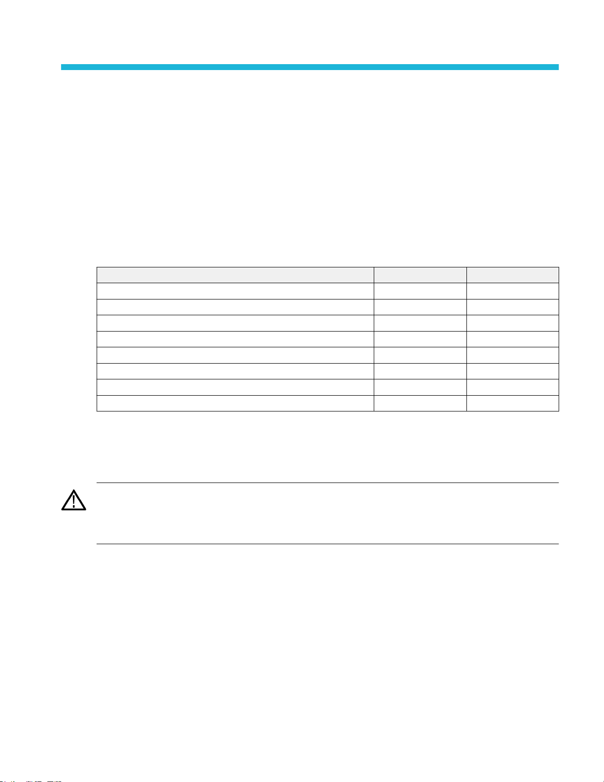
Power requirements
Characteristic Description
Power source voltage 100 V - 240 V
Power source frequency 50/60 Hz, 100-240 V
400 Hz, 115 V
Power consumption All models: 400 W maximum
, ±10%, single phase
AC RMS
2 MSO64 Installation and Safety Manual
Page 17
Installing your instrument
Input signal requirements
Keep the input signals within allowed limits to ensure the most accurate measurements and prevent damage to the analog and
digital probes or instrument.
Make sure that input signals are within the following requirements.
Input Description
Analog input channels, 1 M Ω setting, maximum
input voltage at BNC
Analog input channels, 50 Ω setting, maximum
input voltage at BNC
Digital input channels, maximum input voltage
range at digital inputs
Ref In maximum input voltage at BNC (rear panel) 7 V
AUX trigger input ±5 V
300 V
RMS
Transient Overvoltage is 0V. The measuring terminals on this product are
not rated for connection to mains or Category II, III, or IV circuits.
5 V
RMS
Transient Overvoltage is 0V. The measuring terminals on this product are
not rated for connection to mains or Category II, III, or IV circuits.
Observe probe ratings
TLP058; ±42 V
PP
RMS
P
Secure (lock) the oscilloscope
Lock an oscilloscope to a test bench or equipment rack to prevent property loss.
Attach a standard laptop security lock to the rear panel of the oscilloscope, to secure the oscilloscope to a workbench, rack, or
other location.
MSO64 Installation and Safety Manual 3
Page 18

Installing your instrument
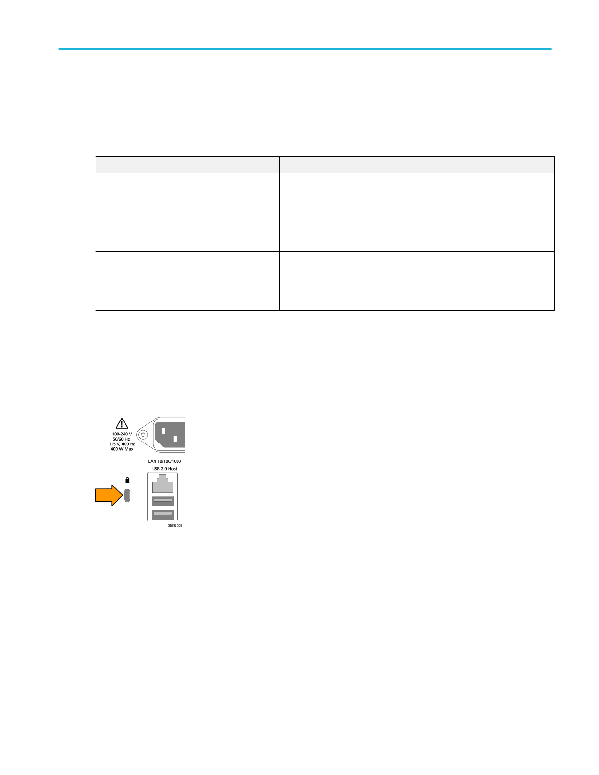
Powering the oscilloscope
Use this procedure to connect the oscilloscope to line power and power on and off the oscilloscope. Always connect the
oscilloscope to AC power using the power cord that shipped with the instrument.
Prerequisite: Use the AC power cord that shipped with your oscilloscope.
1. Connect the supplied power cord to the oscilloscope power connector.
Figure 1: MSO6 Series power cord connector and power standby switch
2. Connect the power cord to an appropriate AC mains source.
Power is supplied to the power supply and some other boards whenever the AC power cord is connected to a live mains
circuit, putting the instrument in standby mode.
3. Push the front panel power button to power the instrument on and off.
The power button color indicates instrument power states:
Unlit – no AC power applied
Yellow – standby mode
Blue – powered on
4. To completely remove power from the instrument, disconnect the power cord.
5. To transport the instrument with its power cord, flip out the power cord supports on the upper edge of the rear panel and
wrap the power cord around the supports.
4 MSO64 Installation and Safety Manual
Page 19
Installing your instrument
Check that oscilloscope passes power-on self tests
Power-on self tests verify that all oscilloscope modules are working correctly after power up.
1. Power on the oscilloscope and wait until the oscilloscope screen appears.
2. Select Utility > Self Test from the top-edge Menu bar to open the Self Test configuration menu.
3. Check that the status of all power-on self tests are Passed.
If one or more power-on self tests shows Failed:
a. Power cycle the oscilloscope.
b. Tap Utility > Self Test. If one or more power-on self tests still shows Failed, contact Tektronix Customer Support.
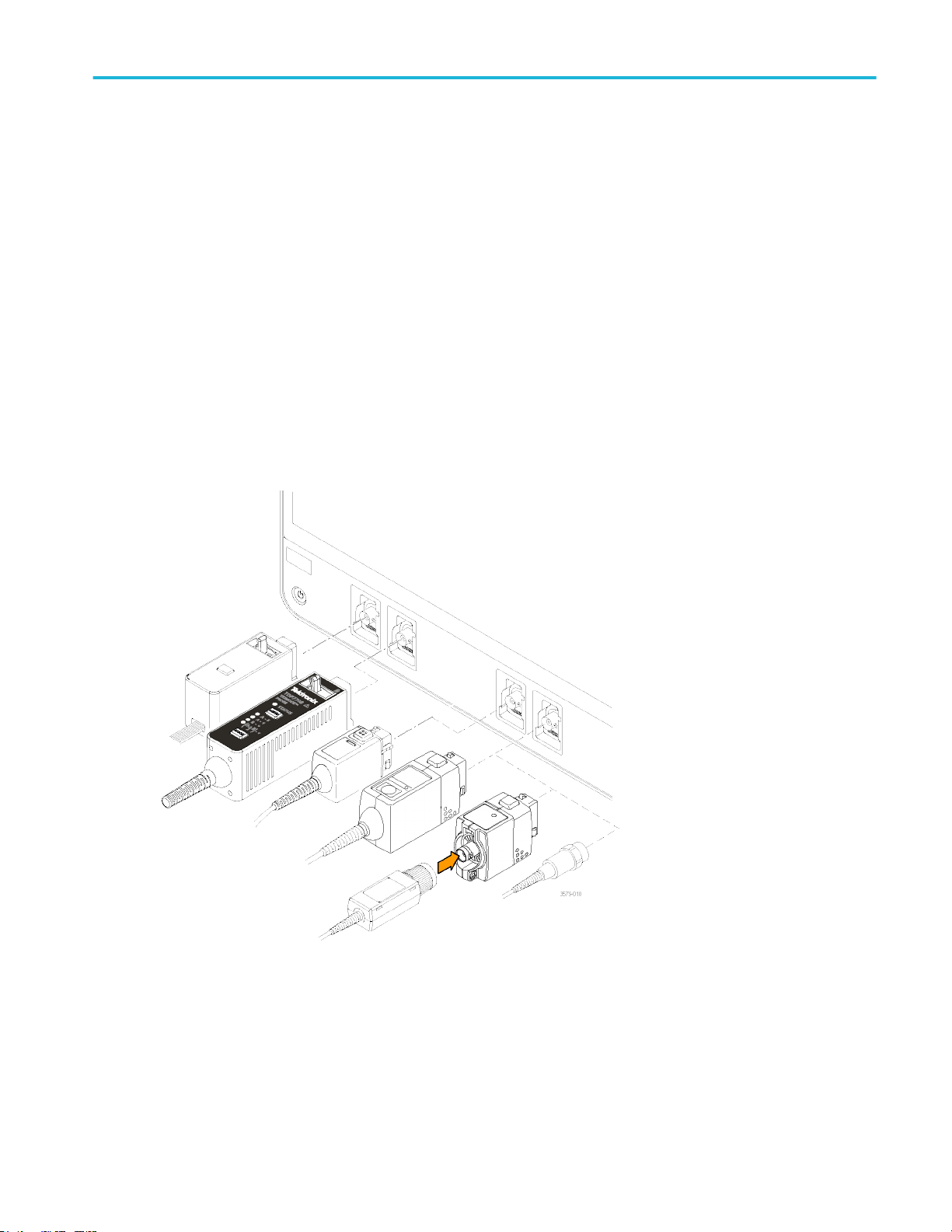
Connecting Probes
Probes and cables connect the oscilloscope to your device under test (DUT). Use a probe that best matches your signal
measurement needs.
Figure 2: Connecting probes to the MSO6 Series
Connect TPP0500B, TPP1000, TekVPI+, TekVPI, or other supported Tektronix analog probes by pushing them into a
FlexChannel connector. The probe base latch locks with a 'click' when the probe is fully seated.
TekVPI probes automatically set the channel input parameters for that probe (bandwidth, attenuation, termination, and so on). If
a probe has a Menu button, push that button to open an on-screen configuration menu. Follow instructions provided with active
probes to set their parameters (auto zero, degauss, and so on).
MSO64 Installation and Safety Manual 5
Page 20

Installing your instrument
To connect a TLP058 FlexChannel Logic Probe or a TDP7700 Series TriMode™ Probe:
1. Move the locking lever to the unlocked position, then let go to reset locking lever to the center position.
2. Insert the probe into a FlexChannel connector until fully seated and the lock mechanism clicks.
3. Move the locking lever to the locked position. The status light should be a solid green.
4. To disconnect the TLP058 probe, move and hold the locking lever at the unlocked position and pull out the probe. Do not
pull on the ribbon cable while removing the probe.
Connect a BNC probe or cable by pushing it onto a channel BNC bayonet connector and turn the lock mechanism clockwise until
it locks.
NOTE. Connecting a probe does not automatically enable that channel (make it active). Use the instrument controls or
programmatic interface to turn on a channel and open its configuration menu to verify or change probe or cable settings
(bandwidth, attenuation, termination and so on).
Rackmount information
The optional RM5 Rackmount Kit lets you install the oscilloscope in standard equipment racks. The rack mount requires seven
rack units (7U) of space to install.
6 MSO64 Installation and Safety Manual
Page 21

Getting acquainted with your instrument
The following content provides a high-level description of the instrument controls and user interface.
Refer to the instrument help for detailed information on using the controls and user interface to display waveforms and take
measurements.
Front panel controls and connectors
The front panel controls provide direct access to key instrument settings such as vertical, horizontal, trigger, cursors, and zoom.
The connectors are where you input signals with probes or cables, or insert USB devices.
Figure 3: 6 Series MSO controls
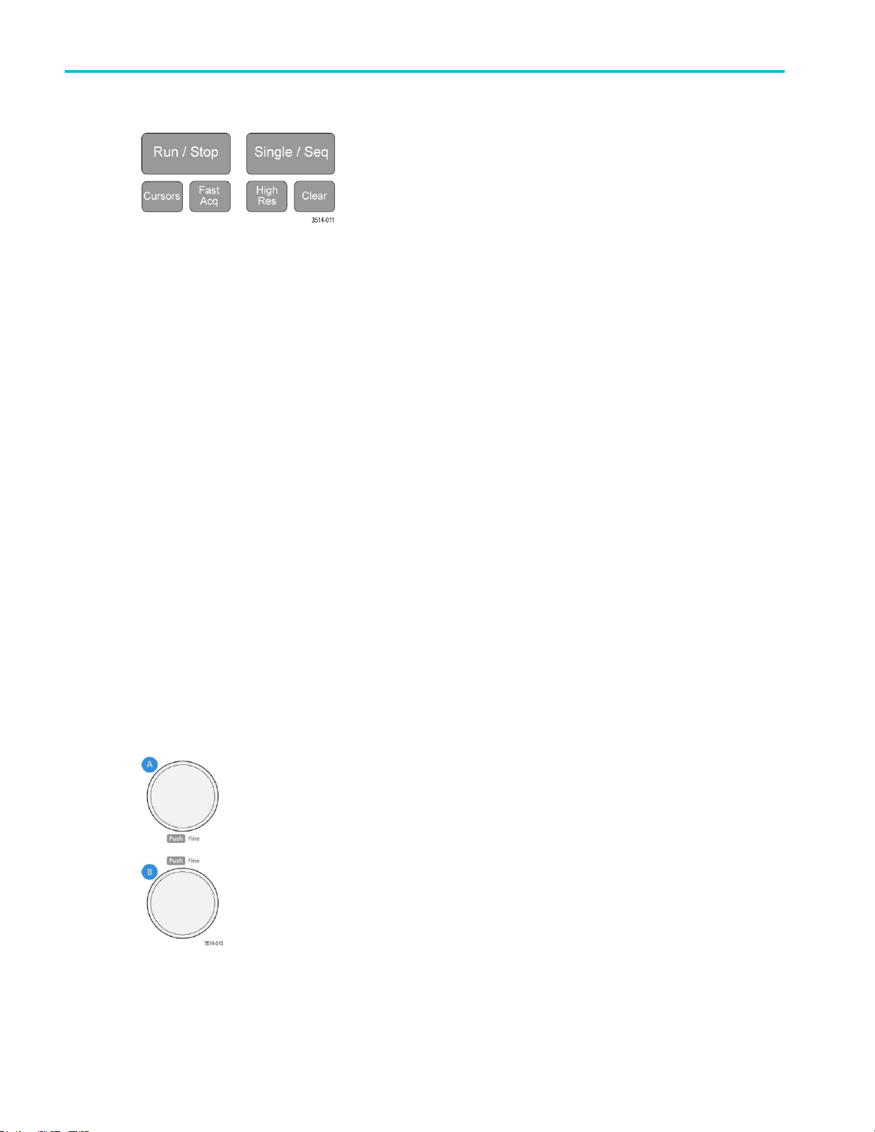
1. Acquisition and Cursors controls:
MSO64 Installation and Safety Manual 7
Page 22
Getting acquainted with your instrument
■
Run/Stop starts and stops waveform acquisition. The button color indicates the acquisition status (green = running and
acquiring; red = stopped). When stopped, the oscilloscope shows waveforms from the last completed acquisition. The
Run/Stop button on the screen also shows the acquisition status.
■
Cursors button turns screen cursors on or off. Use the Multipurpose knobs to move the cursors. Double-tap the cursor
readouts, or on a cursor bar (line), to open the configuration menu to set cursor types and functionality. See Display
and configure cursors on page 49.
■
Fast Acq™ enables or disables the fast acquisition mode. FastAcq provides high-speed waveform capture that
reduces the dead time between waveform acquisitions, enabling the capture and display of transient events such as
glitches and runt pulses. It is helpful in finding elusive signal anomalies. Fast acquisition mode can also display
waveform phenomena at an intensity that reflects their rate of occurrence.
■
Single/Seq enables making a single waveform acquisition, or a specified number of acquisitions (as set in the
Acquisition configuration menu). Pushing Single/Seq turns off Run/Stop mode and takes a single acquisition. The
button color indicates the acquisition status (quick green flash = single acquisition acquired; solid green = waiting for
trigger event). Pushing Single/Seq again takes another single acquisition.
■
High Res applies unique finite impulse response (FIR) filters based on the current sample rate. This FIR filter
maintains the maximum bandwidth possible for that sample rate while rejecting aliasing. The filter removes noise from
the oscilloscope amplifiers and ADC above the usable bandwidth for the selected sample rate. Implementation of the
filter in hardware, ahead of the trigger and storage, reduces trigger jitter and enables using Fast Acq mode while in
High Res mode.
High Res mode also guarantees at least 12 bits of vertical resolution. The number of bits of resolution is displayed in
the Acquisition badge at the bottom of the screen. The Horizontal badge also updates to show the sample rate and
record length settings while in High Res mode.
■
Clear deletes the current acquisitions and measurement values from memory.
2. Multipurpose knobs:
■
Multipurpose knobs (A, B) The Multipurpose knobs A and B move cursors and set parameter values in configuration
menu input fields. Selecting an menu field that can use a Multipurpose knob assigns the indicated knob to change the
value in that input field. The ring around each knob lights when you can use that knob to do an action.
8 MSO64 Installation and Safety Manual
Page 23
Getting acquainted with your instrument
Push a Multipurpose knob to enable the Fine mode for making smaller increment changes. Push the knob again to exit
Fine mode.
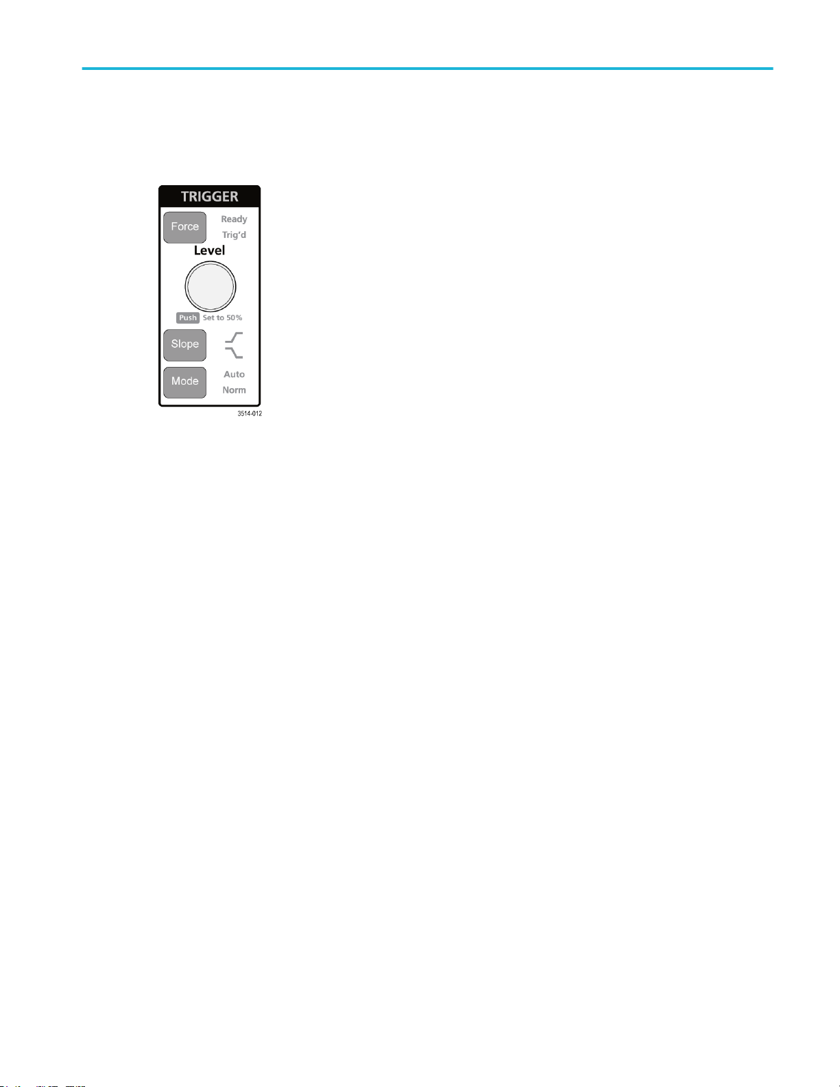
3. Trigger controls:
■
Force forces a trigger event at a random point in the waveform and captures the acquisition.
■
Level sets the amplitude level that the signal must pass through to be considered a valid transition. The color of the
Level knob indicates the trigger source except for dual-level triggers. The Level knob is disabled when the trigger type
requires two level settings or other trigger qualifiers (set from the Trigger configuration menu). Push the knob to set the
threshold level to 50% of the peak-to-peak amplitude range of the signal.
■
Slope sets the signal transition direction to detect for a trigger (low to high, high to low, or either direction). Push the
button to cycle through the selections. The Slope button is disabled when the trigger type requires other slope
qualifiers (set from the Trigger configuration menu).
■
Mode sets how the instrument behaves in the absence or presence of a trigger event:
■
Auto trigger mode enables the instrument to acquire and display a waveform whether or not a trigger event
occurs. If a trigger event occurs, the instrument displays a stable waveform. If a trigger event does not occur, the
instrument forces a trigger event and acquisition and displays an unstable waveform.
■
Normal trigger mode sets the instrument to acquire and display a waveform only when there is a valid trigger
event. If no trigger occurs, the last waveform record acquired remains on the display. If no last waveform exists,
no waveform is displayed.
MSO64 Installation and Safety Manual 9
Page 24

Getting acquainted with your instrument
4. Vertical controls:
■
Position moves the selected waveform (Channel, Math, Reference, Bus) and its graticule up or down on the screen.
The color of the Position knob indicates which waveform the knob is controlling. Push the knob to set the threshold
level to 50% of the peak-to-peak amplitude range of the signal.
■
Scale sets the amplitude units per vertical graticule division of the selected waveform. The scale values are shown on
the right edge of the horizontal graticule lines, and are specific to the selected waveform in both Stacked or Overlay
modes (in other words, each waveform has its own unique vertical graticule settings regardless of display mode). The
color of the Scale knob indicates which waveform the knob is controlling.
■
Channel(1-4) buttons turn on (display), select, or turn off a channel, as follows:
■
If the channel is not displayed, pushing a Channel button turns on that channel to the Waveform view.
■
If the channel is on the screen and is not selected, pushing that channel's button selects that channel.
■
If the channel is on the screen and is also selected, pushing that channel's button turns that channel off (removes
it from Waveform view).
■
The Math button adds or selects a Math waveform on the Waveform view, as follows:
■
If no Math waveform exists, pushing the Math button adds a Math waveform to the Waveform view and opens the
Math configuration menu.
■
If only one Math waveform is displayed, pushing the button turns off the Math waveform (removes it from
Waveform view). Push the button again to display the waveform.
■
If two or more Math waveforms are displayed, pushing the button cycles through selecting each math waveform.
■
The Ref button adds or selects a Reference (saved) waveform on the Waveform view, as follows:
■
If no Reference waveform exists, pushing the Ref button opens the Browse Waveform Files configuration menu.
Navigate to and select a waveform file (*.wfm) and tap Recall to load and display the reference waveform.
■
If only one Reference waveform is displayed, pushing the button turns off the Reference waveform (removes it
from the Waveform View). Push the button again to display the waveform.
■
If two or more Reference waveforms are displayed, pushing the button cycles through selecting each Reference
waveform.
■
The Bus button adds or selects a bus waveform on the Waveform view, as follows:
■
If no Bus waveform exists, pushing the Bus button adds a Bus waveform to the Waveform view and opens the
Bus configuration menu.
■
If only one Bus waveform is displayed, pushing the button turns off the Bus waveform (removes it from Waveform
view).
■
If two or more Bus waveforms are displayed, pushing the button cycles through selecting each Bus waveform.
10 MSO64 Installation and Safety Manual
Page 25
Getting acquainted with your instrument
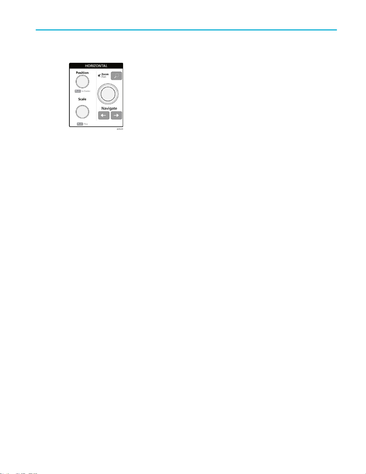
5. Horizontal controls:
■
Position moves the waveform and graticule side to side on the screen (changing the trigger point position in the
waveform record). Push the knob to center the trigger event to the center graticule on the Waveform view.
■
Scale sets the time per major horizontal graticule division and samples/second parameters for the oscilloscope. Scale
applies to all waveforms. Push the knob to enable the Fine mode for making smaller increment changes. Push the
knob again to exit Fine mode.
■
Zoom opens the Zoom mode. Push Zoom again to exit zoom mode. See The Zoom user interface elements on
page 28.
■
Zoom knob (center knob) increases or decreases the area of the zoom box in the Zoom Waveform Overview, which in
turn controls the zoom amount of the waveforms shown in the main Zoom view.
■
Pan knob (outer knob) moves the Zoom box left or right in the Zoom Waveform Overview, which in turn controls the
part of the waveform shown in the main Zoom view.
■
Navigate (left and right arrow) buttons puts the oscilloscope in Zoom mode and positions the previous or next search
point in the waveform record to the center graticule of the Waveform view. There must be a Search badge present in
the Results bar before the Navigate function will operate. Press and hold a front panel navigate button to continue
moving to the next search point in that direction. See Badges on page 20.
The front panel Navigate buttons can also be used for the Previous and Next button functions on measurement
badges.
MSO64 Installation and Safety Manual 11
Page 26
Getting acquainted with your instrument
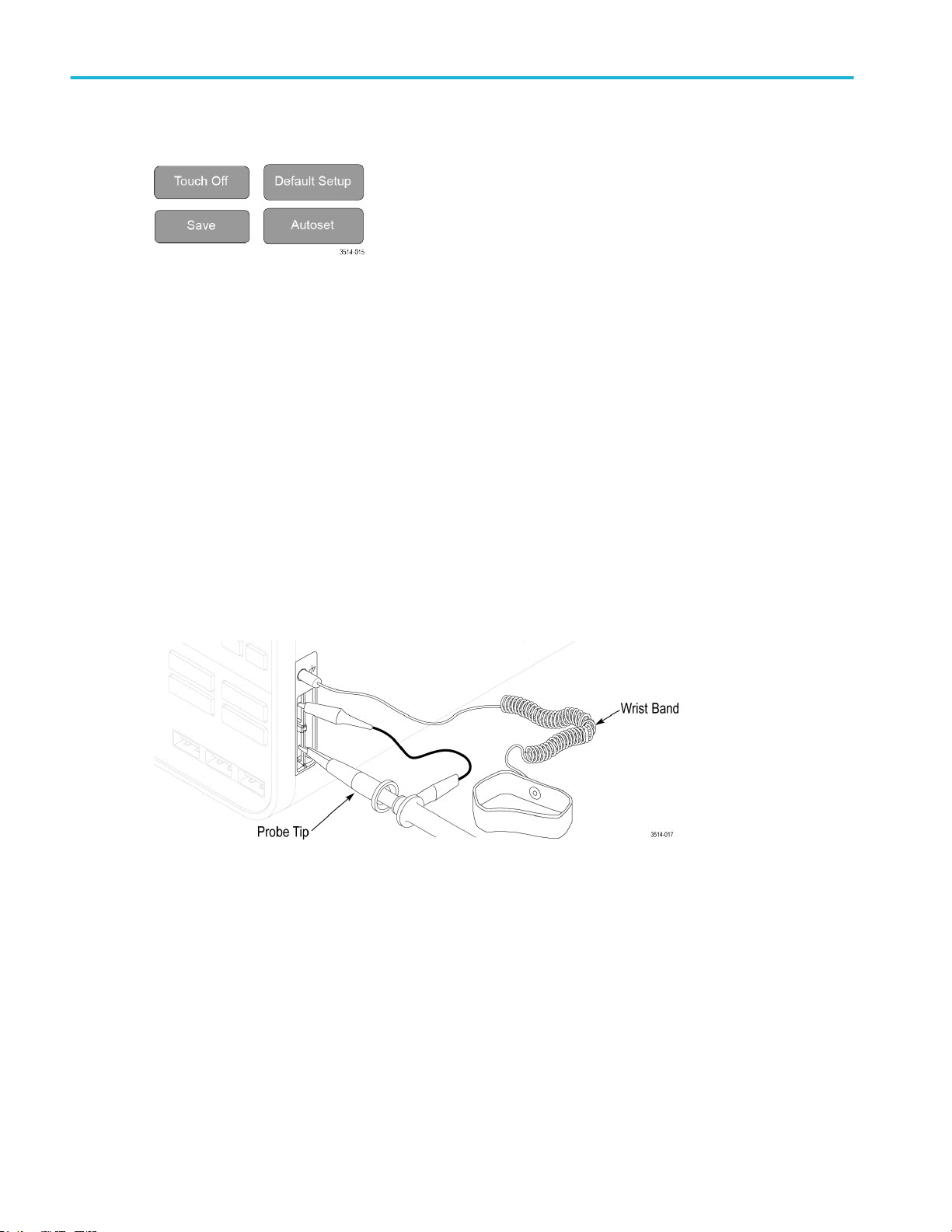
6. Miscellaneous controls:
■
Touch Off turns touch screen capability off. The Touch Off button is lighted when the touch screen is turned off.
■
Save is a one-push save operation that uses the current File > Save As settings to save screen shots (including open
menus and dialog boxes), waveform files, instrument settings, and so on, as follows:
■
If a File > Save or File > Save As operation has occurred since the last instrument startup, pushing Save saves
the file types to the location last set in the Save As configuration menu.
■
If no file save operation has occurred since the last instrument startup, pushing Save opens the Save As
configuration menu. Select a tab to select the type of file to save (Screen Capture, Waveform, and so on), set any
associated parameters, and where to save it, and select OK. The specified file or files are saved. The next time
you push Save, the same type files are saved.
■
Screen Captures capture the entire screen, including most displayed configuration menus and dialog boxes.
■
Default Setup restores the oscilloscope settings (horizontal, vertical, scale, position, and so on) to the factory default
settings.
■
Autoset automatically displays a stable waveform. See Quickly display a waveform (Autoset) on page 37.
7. Ground and Probe Compensation connectors:
■
The Ground and Probe Compensation connectors are located at the lower right side of the instrument, near the front
panel. The Ground connector (the small hole in the case) provides an electrically grounded (through a resistor)
connection point to attach an anti-static wrist strap, to reduce electrostatic damage (ESD) while you handle or probe
the DUT.
■
The Probe Compensation connections provide a ground connector (upper tab) and 1 kHz square wave source (lower
tab) for adjusting the high-frequency response of a passive probe (probe compensation). The oscilloscope uses this
signal to automatically compensate supported probes, including the ones that ship with the product. See Compensate
the TPP0500B or TPP1000 probes on page 32.
12 MSO64 Installation and Safety Manual
Page 27
Getting acquainted with your instrument
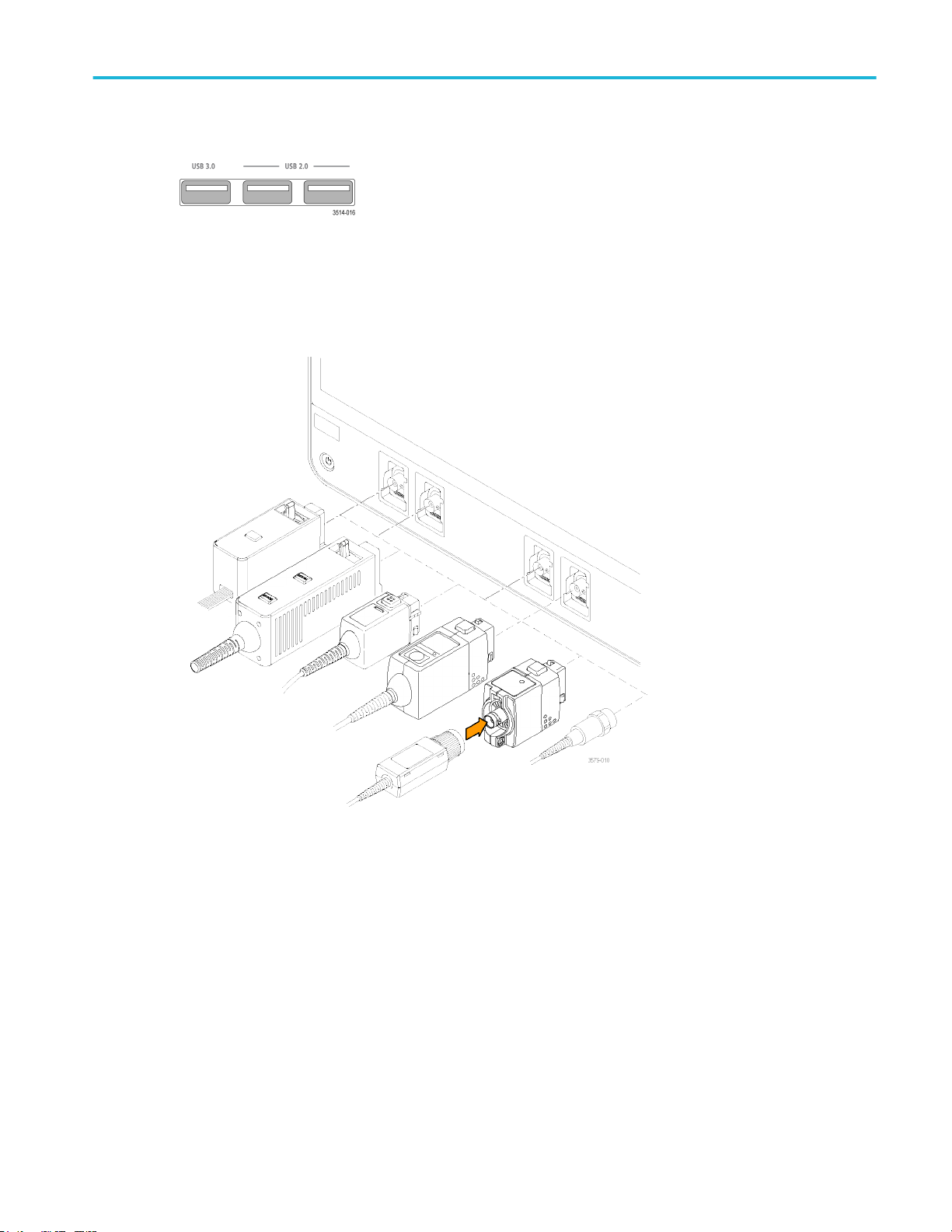
8. USB Host ports (USB 3.0 and 2.0):
■
USB ports are located at the lower right corner of the front panel, and on the rear panel. Connect USB flash drives to
which you can save or recall data (such as instrument software updates, waveforms, settings, and screen captures), or
connect peripheral devices such as a mouse or keyboard.
9. FlexChannel probe connectors:
■
FlexChannel connectors support all TekVPI+ and TekVPI measurement probes, BNC passive probes, the TPL058
FlexChannel Logic Probe, and BNC cables. You connect most probes simply by pushing them into the connector until
the probe seats with a click. See Connecting Probes on page 5.
10. Aux Trig trigger input connector:
An SMA connector to which you can connect an external trigger input signal. Use the AUX In trigger signal with the Edge
trigger mode.
MSO64 Installation and Safety Manual 13
Page 28

Getting acquainted with your instrument
Rear panel connections
The rear panel connections supply power to the oscilloscope and provide connectors for network, USB devices, video, reference
signals, and the AFG output.
1. Power cord connector. Use only the power cord specified for this product and certified for the country of use.
2. Ref In lets you connect a high-precision 10 MHz reference signal to the oscilloscope for more accurate measurements.
3. AUX Out generates a signal transition on a trigger event, outputs a 10 MHz reference signal, or outputs a synchronization
signal from the AFG.
4. AFG Out is the signal output for the optional Arbitrary Function Generator (AFG) feature.
5. Video outputs (Display Port, VGA, and DVI-D) let you connect an external monitor or projector to show the oscilloscope
screen.
6. USB Device port lets you connect to a PC to remotely control the oscilloscope using USBTMC protocol.
7. USB Host ports let you connect a USB memory device, keyboard, or mouse.
8. LAN connector (RJ-45) connects the oscilloscope to a 10/100/1000 Base-T local area network.
9. Security lock connector lets you use a standard PC/laptop lock cable to secure the oscilloscope to a work bench or other
location.
14 MSO64 Installation and Safety Manual
Page 29
Getting acquainted with your instrument
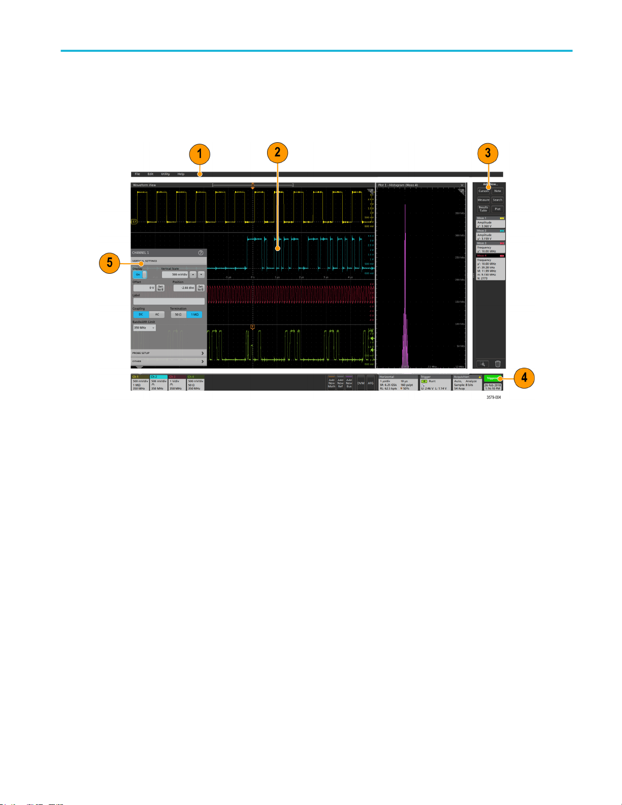
The user interface screen
The touch screen user interface contains waveforms and plots, measurement readouts, and touch-based controls to access all
oscilloscope functions.
1. The Menu bar provides menus for typical operations including:
■
Saving, loading, and accessing files
■
Undoing or redoing an action
■
Setting oscilloscope display and measurement preferences
■
Configuring network access
■
Running self tests
■
Erasing measurement and settings memory (TekSecure™)
■
Loading option licenses
■
Opening a Help viewer.
2. The Waveform View area displays analog, digital, math, reference, bus, and trend waveforms. The waveforms include
waveform handles (identifiers), individual vertical graticule scale labels, and trigger position and level(s) indicators. You can
set the Waveform View to stack each waveform vertically in separate graticules, called 'slices' (the default mode, as shown
in the previous image), or overlay all the waveforms on the screen (traditional waveform view). See The user interface
elements on page 16.
You can also add Histogram, Spectral, Eye, and Measurement Results views (plots) for individual measurements. These
plot views are separate view windows that you can move on the screen by dragging their title bar to a new position.
MSO64 Installation and Safety Manual 15
Page 30

Getting acquainted with your instrument
3. The Results Bar contains controls for displaying cursors, adding notes, plots, and result tables to the screen, and add
measurements to the Results bar. The controls are:
■
The Cursors button displays on-screen cursors in the selected view. Touch and drag, or use the Multipurpose knobs,
to move the cursors. Double-tap on a cursor, or on the cursor readouts, to open a configuration menu to set cursor
types and related functions.
■
The Measure button opens a configuration menu from which to select and add measurements to the Results bar. Each
measurement you add has a separate badge. Double-tap a measurement badge to open its configuration menu.
■
The Results Table button adds a Measurement or Bus Results table to the screen. The Measurement Results table
displays all measurements present in the Results bar. The Bus Results table displays bus decode information for
displayed bus waveforms. Each table is contained within its own view window, which can be moved within the display
area.
■
The Note button adds a note object to the selected view. Double-tap the note text to open a configuration menu to
change the text and font characteristics. Drag the note to any location on the view. Notes cannot be added to a
Results Table view.
■
The Search button lets you detect and mark a waveform where specified events occur. Tap Search to open a Search
configuration menu and set the search conditions for analog and digital channels. You can add any number of
searches to the same waveform or to different waveforms. Search badges are added to the Results Bar.
■
The Plot button adds an XY, XYZ, or Eye Diagram plot to the display. These plots are contained within their own
window and can be moved within the overall display area.
■
The Measurement and Search badges show measurement and search results, and are displayed in the Results Bar.
See Badges on page 20. See Add a measurement on page 42. See Add a Search on page 47.
■
The Draw-a-Box button at the bottom of the Results Bar lets you toggle between drawing a box on the screen to
zoom in on an area of interest, or drawing areas to define visual trigger conditions.
■
The Trash Can icon lets you drag Channel, Waveform, Measurement, and Search badges to the Trash Can to delete
them.
4. The Settings Bar contains System badges for setting Horizontal, Trigger, Acquisition, and Date/Time parameters; Inactive
Channel buttons to turn on channels; Add New Waveform buttons to add math, reference, and bus waveforms to the
display; and Channel and Waveform badges that let you configure the individual waveform parameters. Tap a channel or
waveform button to add it to the screen and display a badge. Double-tap a badge to open its configuration menu. See
Badges on page 20.
5. Configuration Menus let you quickly change the parameters of the selected user interface item. You can open
configuration menus by double-tapping on badges, screen objects, or screen areas. See Configuration menus on page 26.
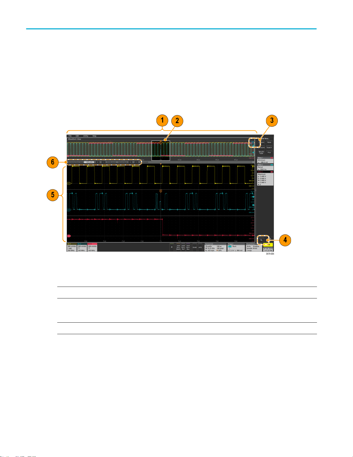
The user interface elements
Each area of the user interface has a specific function that helps manage information or controls. This topic shows and describes
the key user interface elements.
16 MSO64 Installation and Safety Manual
Page 31

Getting acquainted with your instrument
1. The Waveform Record View is a graphical high-level view of the overall waveform record length, how much of the record is
on the screen (shown in brackets), the location of key time events including the trigger event, and the current position of
waveforms cursors.
If you are displaying a Reference waveform that is shorter than the current acquisition record length, or you are changing
the horizontal time scale while the oscilloscope acquisition is stopped, the brackets change position to show the part of the
waveform record that is being viewed relative to the current acquisition total record length.
If cursors are active on a waveform, the Waveform Record View shows the relative cursor positions as small vertical dashed
lines.
MSO64 Installation and Safety Manual 17
Page 32

Getting acquainted with your instrument
When in Zoom mode, the Waveform Record View is replaced with the Zoom Overview. See The Zoom user interface
elements on page 28.
2. The Expansion Point icon on the waveform view shows the center point around which the waveform expands and
compresses when changing horizontal settings.
3. The Trigger Position Indicator shows where the trigger event occurred in the waveform record. The trigger icon is displayed
in the waveform slice that is the trigger source.
4. The Zoom icon (in upper right corner of Waveform and Plot views) toggles zoom on and off. The front panel Zoom button
and knobs also turn on zoom mode and change the position and horizontal size of the Zoom Box.
5. The Trigger Level Indicator icon(s) shows the trigger level on the trigger source waveform. Some trigger types require two
trigger levels.
6. Measurement and Search badges show measurement and search results. See Badges on page 20. See Add a
measurement on page 42.
7. The Results Bar Handle opens or closes the Results bar, to maximize waveform screen viewing when needed. To reopen
the Results bar, either tap the handle icon or swipe left from the right side of the display.
8. The System badges show global instrument settings (Horizontal, Trigger, Acquisition, Run/Stop status, and Date/Time).
See Badges on page 20.
9. The Inactive Channel buttons add channel waveforms to the Waveform view and add an associated Channel badge to the
Settings bar.
The Add New Math, Add New Ref, and Add New Bus buttons add the corresponding signal to the Waveform view, and
add an associated Waveform badge to the Settings bar. You can add any number of Math, Reference, and Bus waveforms,
limited only by system memory.
The optional AFG button opens the AFG configuration menu to set and enable the AFG output. This button is only present if
the AFG option is installed.
The optional DVM button lets you use an analog probe to take DC, AC RMS, or DC+AC RMS voltage measurements on
your DUT. Tap the button to add a DVM badge to the Results Bar and open a configuration menu. The DVM option also
enables a trigger frequency counter, accessible from the Mode & Holdoff panel in the Trigger badge menu. This button is
only present if the DVM option is installed.
10. Double-tap a badge to open its associated configuration menu. See Badges on page 20. See Configuration menus on
page 26.
If you add more Channel or Waveform badges than can fit in the waveform badge display area, tap the scroll buttons at
each end of the waveform badge area to scroll and display hidden badges.
18 MSO64 Installation and Safety Manual
Page 33

Getting acquainted with your instrument
11. The Waveform Handles on each waveform identify the source of that waveform (Cx for channels, Mx for Math waveforms,
Rx for Reference waveforms, Bx for bus waveforms). The waveform handles are at the zero-volt level of the waveform by
default. The currently selected waveform handle is a solid color; unselected waveform handles are outlined.
Double-tapping a waveform handle opens the configuration menu for that waveform.
For digital channels, the waveform handle shows the channel number, each individual digital signal labeled D0–D7 and
displayed with a different color.
Double-tapping a digital waveform handle opens the digital channel configuration menu.
Dragging a digital signal handle over another handle swaps those two signals on the waveform.
12. The probe Dynamic Range Limit Markers are displayed just within the left-hand graticule edge, based at the channel vertical
trace handle position and extending up and down to the dynamic range limits of the probe. The markers are only displayed if
compatible probes are used. Signals must be within the probe dynamic range for the oscilloscope to correctly display and
measure the signals.
The markers are displayed, for about three seconds, after any Offset, Position, or Scale control change that leaves the
channel dynamic range limits within the acquisition window. After about three seconds the markers become short lines at
the left edge of the graticule. If the dynamic range is too small to display the arrows, the arrows are omitted. Examples of all
three marker versions are shown.
MSO64 Installation and Safety Manual 19
Page 34

Getting acquainted with your instrument
Badges
Badges are rectangular icons that show waveform, measurement, and instrument settings or readouts. Badges also provide fast
access to configuration menus. The badge types are Channel, Waveform, Measurement, Search, and System.
Channel and Waveform badges
Channel and Waveform (Math, Ref, Bus, Trend) badges are shown in the Settings Bar, located along the bottom left of the
screen. Each waveform has its own badge. The badges show high-level settings for each displayed channel or waveform.
Double-tap a badge to open its configuration menu.
Most Channel and Waveform badges also have Scale buttons, shown by single-tapping the badge. Use the Scale buttons to
increase or decrease the vertical scale setting for that waveform.
You can drag Channel and Waveform badges to change their position in the Settings bar, or drag them into the Trash Can icon
to turn them off.
Channel badges are listed in the channel order unless you have moved them. Channel badges may also display short error or
warning messages. For more information double-tap the badge to open its configuration menu, or search the instrument Help.
Waveform badges (Math, Ref, Bus, Trend) are listed in the order created (unless they have been moved), and are grouped
together by type. Deleting a Waveform badge does not change the order or names of the remaining badges.
Measurement badges
Measurement badges are located in the Results Bar. They show measurements or search results. The badge title also shows
the measurement source or sources. To add a Measurement badge, tap the Add New Measurement button and select a
measurement.
20 MSO64 Installation and Safety Manual
Page 35

Getting acquainted with your instrument
Double-tap a Measurement badge to open its configuration menu to change or refine settings. The default measurement badge
readout shows the measurement's mean (μ) value.
Some measurements and their badges are only available as options. For example, Power measurements are only listed in the
Add New Measurement menu if the PWR option is installed.
To add statistical readouts to individual measurement badges, double-tap a measurement badge to open its configuration menu
and select Show Statistics in Badge.
Some Measurement badges also have Navigation buttons, shown by single-tapping the badge.
The < (Previous) and > (Next) buttons center the waveform in the display at the position of the previous or next measurement
point in the record (for measurements that take more than one measurement per acquisition).
MSO64 Installation and Safety Manual 21
Page 36

Getting acquainted with your instrument
The Min' and Max' navigation buttons center the waveform in the display at the minimum or maximum value for that
measurement in the current acquisition.
The prime symbol (') shown on measurement readings and Min/Max buttons indicates that the value shown (or moved to in the
case of Min/Max buttons and waveforms) is from the current acquisition. Lack of a prime symbol means the value is from all
acquisitions.
Measurement badges are listed in the order created, starting at the top of the Results bar. Deleting a Measurement badge does
not change the order or names of the remaining badges.
You can drag Measurement badges to change their position in the Results bar, or drag them into the Trash Can icon to delete
them.
Search badges
Search badges are also shown in the Results Bar, below the Measurement badges. A search badge lists the search source,
search type, and the number of search event occurrences in the current acquisition. The instrument marks the waveform where
those events occur with small down-pointing triangles along the top of the waveform graticule. Double-tap a search badge to
open its configuration menu to change or refine search settings.
Search badges are created by tapping the Add New... Search button. Use the displayed configuration menu to set the search
criteria.
Search badges have < (Previous) and > (Next) Navigation buttons that open the Zoom mode and center the waveform in the
display at the position of the previous or next search mark in the waveform record. Search badge Navigation buttons are only
usable when the oscilloscope is in single acquisition mode. Single-tap a badge to close the Navigation buttons.
Some searches also provide Min and Max navigation buttons that open the Zoom mode and center the waveform in the display
at the minimum or maximum value for that search event in the current acquisition.
Search badges are listed in the order created. Deleting a Search badge does not change the order or names of the remaining
badges.
You can drag Search badges to change their position in the Results bar, or drag them into the Trash Can icon to delete them.
22 MSO64 Installation and Safety Manual
Page 37

Getting acquainted with your instrument
Signal Clipping and Badges
WARNING. Clipping is caused by excessive or dangerous voltage at the probe tip, and/or a vertical scale setting that is not
adequate to display the entire vertical range of the waveform. Excessive voltage at the probe tip can injure the operator and
cause damage to the probe and/or instrument.
This instrument shows a warning triangle symbol and the words Clipping in a Channel badge when a vertical clipping condition
exists. Any measurement badges associated with that channel also indicate a clipping condition by turning the measurement text
red and listing the type of clipping (positive or negative).
To close the clipping message, change the vertical scale to show the entire waveform, disconnect the probe tip from the
excessive voltage source, and check that you are probing the correct signal using the correct probe.
Clipping causes inaccurate amplitude-related measurement results. Clipping also causes inaccurate amplitude values in saved
waveform files. If a math waveform is clipped, it will not affect amplitude measurements on that math waveform.
Error Messages and Badges
This instrument shows a warning triangle symbol and an error message abbreviation in a Channel badge when an error occurs.
To remove the message from the badge, clear the error as indicated in the table.
Table 1: Probe errors
Error message Description
Prb Comm Accessory communication timed out. Please re-attach the accessory.
Prb ROM Unable to read probe ROM. Please re-attach the accessory.
Unsup Accessory is unsupported.
Prb Fault Critical accessory fault. Please re-attach the accessory. If the problem persists, contact Tektronix service.
Over Rng The signal voltage or current is over range. Please reduce the signal amplitude.
Temp The probe has experienced an over temperature condition. Please remove the probe from the high
temperature area.
MSO64 Installation and Safety Manual 23
Page 38

Getting acquainted with your instrument
Error message Description
No Tip No probe tip detected. Please install a compatible probe tip.
Tip Fault The probe tip has a fault. Please remove and replace the probe tip.
S-param Error during S-parameter transfer. Please reattach the probe. If the problem persists, contact Tektronix
Service.
System badges
System badges (in the Settings bar) display the main Horizontal, Trigger, and Acquisition settings. You cannot delete System
badges.
Double-tap a System badge to open its configuration menu.
The Horizontal badge also has Scale buttons, shown by single-tapping the badge. Use the Horizontal Scale buttons to increase
or decrease the horizontal time setting.
24 MSO64 Installation and Safety Manual
Page 39

Getting acquainted with your instrument
Common badge actions
Action Result Example
Single tap Immediate access controls (Scale,
Navigation).
Double tap Configuration menu with access to
all settings for the badge.
Touch and hold Right-click menu with single tap
access to common actions. Typical
actions include turning off a
channel and deleting a
measurement or search badge.
MSO64 Installation and Safety Manual 25
Page 40

Getting acquainted with your instrument
Badge selection status
The appearance of a badge indicates its selection status (selected or unselected), or if a measurement needs to be deleted to
close a channel or waveform badge.
Badge type Selected Unselected Turned off or in use
Channel or
Waveform
Measurement N/A
1
Configuration menus
Configuration menus let you quickly set the parameters for channels, system settings (Horizontal, Trigger, Acquisition),
measurements, cursor readouts, Waveform and Plot views, note text, and so on.
Double-tap an item (badge, Waveform View or Plot View, cursor readouts, note text, and so on) to open its configuration menu.
For example, double-tap a Channel badge in the Settings Bar to open its configuration menu.
1
A dimmed Channel badge means the screen waveform is turned off (but not deleted). A dimmed Waveform badge means that the waveform display is turned off, or it is
being used as a source by a measurement and cannot be deleted until the measurement is deleted.
26 MSO64 Installation and Safety Manual
Page 41

Getting acquainted with your instrument
Selections or values that you enter take effect immediately. Menu contents are dynamic, and can change depending on your
selections, instrument options, or attached probes.
Related settings are grouped into 'panels.' Tap the panel name to show those settings. Changes to panel settings can change
the values and/or fields shown in that panel and other panels.
MSO64 Installation and Safety Manual 27
Page 42
Getting acquainted with your instrument
Tap anywhere outside a configuration menu to close it.
To open Help content for a configuration menu, tap the question mark icon in the upper right corner of the menu.
The Zoom user interface elements
Use the zoom tools to magnify waveforms to view signal details.
1. The Zoom Overview shows the entire waveform record. All waveforms are shown in Overlay mode in the Zoom Overview
area.
NOTE. Using pinch and expand gestures on the Zoom Overview waveforms changes the horizontal time base settings.
2. The Zoom Box shows the area of the Zoom Overview to display in the Zoom View (see 5). You can touch and drag the box
to move the area to view. You can also use the zoom Pan knob to move the Zoom Box left or right.
NOTE. Moving the Zoom Box, or changing its position, does not change the horizontal time base settings.
3. The Zoom icon (in the upper right corner of the Waveform View) switches zoom mode on and off.
4. The Draw-a-Box button toggles between drawing a zoom box (default mode) and drawing areas for the Visual Trigger
function. The button is located at the bottom of the Results Bar.
A zoom box lets you quickly draw a box around an area of interest in the Waveform or Zoom Overview. Drawing a box
immediately puts the oscilloscope into zoom mode. To draw a zoom box, tap the Draw-a-Box button (while in Zoom mode),
then touch and drag on the waveform to draw a box waveform. You can continue to draw zoom boxes until you single tap
anywhere on the screen or open a menu.
To toggle between zoom mode and Visual Trigger mode, double-tap the Draw-a-Box button and select Visual Trigger.
Search for the Visual Trigger topics in the oscilloscope embedded Help for more information on Visual Trigger.
28 MSO64 Installation and Safety Manual
Page 43

Getting acquainted with your instrument
5. The Zoom View shows the zoomed waveforms, as marked by the Zoom Box, in the Zoom Waveform Record View. Use
pinch and/or drag options in the zoom view to change the zoomed area of interest.
NOTE. Pinch, expand, and drag gestures in the Zoom View only change zoom magnification settings and Zoom Box
position.
6. Use the Zoom Title Bar controls to adjust the vertical and horizontal size of the zoom area. Click or tap the + or - buttons.
Using the touch screen interface for common tasks
Use standard touch screen actions, similar to those found on smart phones and tablets, to interact with most screen objects. You
can also use a mouse to interact with the UI. The equivalent mouse operation is shown for each touch operation.
The oscilloscope has a user interface tutorial. Tap Help > User Interface Tutorial to quickly learn the fundamental touch
operations.
Table 2: Common touchscreen UI tasks (with mouse equivalents)
Task Touchscreen UI action Mouse action
Add a channel, math, reference, or bus
waveform to the screen.
Select a channel, math, reference, or bus
waveform to make it active
Display scale or navigation buttons on a
badge (waveform, measurement
1
,
search, horizontal).
Open a configuration menu on any item
(all badges, views, cursor readouts,
labels, and so on).
Open a right-click menu (badges, views). Touch and hold on the badge, Waveform
Close a configuration menu
2
. Tap anywhere outside the menu or
Tap an inactive channel button, Add New
Math, Add New Reference, or Add New
Bus button.
Stacked or Overlay mode: Tap the
Channel or Waveform badge.
Stacked mode: Tap the channel, math,
reference, or bus waveform slice or
handle.
Overlay mode: Tap the channel or
waveform handle.
Click an inactive channel button, Add
New Math, Add New Reference, or Add
New Bus button.
Stacked or Overlay mode: Left-click the
Channel or Waveform badge.
Stacked mode: Left-click the channel,
math, reference, or bus waveform slice or
handle.
Overlay mode: Left-click the channel or
waveform handle.
Tap the badge. Click the badge.
Double-tap the badge, view, or other
object.
Double-click the badge, view, or other
object.
Right-click the object.
View, Plot view, or other screen item until
a menu opens.
Click anywhere outside the menu or
dialog.
dialog.
1
Not all measurement or search badges display navigation buttons.
2
Some dialog boxes will not close until you click an OK, Close, or other button in the dialog.
MSO64 Installation and Safety Manual 29
Page 44

Getting acquainted with your instrument
Task Touchscreen UI action Mouse action
Move a menu. Touch and hold the menu title bar or a
blank area in the menu, then drag the
Click and hold the right mouse button on
title or blank area, drag to new position.
menu to new position.
Move a note
3
. Touch and hold on a note and quickly
start to drag, then move to new position.
4
Click and hold the right mouse button on
the note and quickly start to drag, then
move to the new position.
Change horizontal or vertical settings
directly on a waveform.
Vertical changes only apply to the
selected channel or waveform; horizontal
changes apply to all channels and
Tap a badge and use the Scale buttons.
Touch and hold two fingertips on the
waveform view, move them together or
apart vertically or horizontally, lift from
screen; repeat.
Left-click a channel, waveform, or
Horizontal badge and click on the Scale
buttons.
waveforms.
Increase or decrease the zoom area
(while in Zoom mode)
Touch and hold two fingertips on the
waveform view, move them together or
apart vertically or horizontally, lift from
screen; repeat.
Click the + or - buttons on the Zoom Title
bar.
Click the Draw-a-Box button, draw a box
around the waveform area of interest.
Quickly scroll or pan a waveform or list. Touch and drag in the waveform or list. Click and drag in the waveform or list.
Close or open the Results Bar to
increase the Waveform View area.
Tap on the Results Bar Handle (three
vertical dots in border) or anywhere in the
border between the Waveform View and
the Results Bar.
Click the Results Bar Handle (three
vertical dots in border) or anywhere in the
border between the Waveform View and
the Results Bar.
Click and drag the Results Bar divider.
Change the position of badges in the
Settings Bar or Results Bar.
Touch and drag the badge to a new
position in the same bar.
Click and drag the badge to a new
position in the same bar.
3
Notes are screen objects and are not associated with any particular waveform channel or slice.
4
Start to move the note as soon as selected (highlighted), otherwise the UI opens the right-click menu.
30 MSO64 Installation and Safety Manual
Page 45

Configure the instrument
Set the time zone and clock readout format
Set the time zone to your region so that saved files are marked with the correct date and time information. You can also set the
time format (12 or 24 hour clock).
1. Double-tap the Date/Time badge (bottom-right of screen) to open the configuration menu.
2. To turn off showing the date and time on the screen, tap the Display button to Off.
To turn on date/time display again, double-tap in the blank area where the date/time badge was displayed to open the
configuration menu, and set the Display button to On.
3. Select a time format (12 Hour or 24 Hour).
4. Tap the Time Zone field and select the time zone that applies to your location.
5. Tap anywhere outside of the menu to close it.
Download and install the latest firmware
Installing the latest firmware helps ensure that your oscilloscope is taking the most accurate measurements.
Update oscilloscope firmware from a USB drive
Prerequisite: Determine the current version of firmware installed on the oscilloscope (Help > About)
1. Open up a Web browser on a PC and go to www.tek.com/product-support.
2. Enter the oscilloscope model number in the search field and click Go.
3. Scroll down the screen and click the Software tab.
4. If the listed available firmware version (Windows or non-Windows) is newer than what is on your oscilloscope, select and
download that file to your PC.
5. Follow the installation instructions that came with the downloaded firmware to create a firmware install file.
6. Copy the firmware install file to a USB drive.
7. Insert the USB drive into any oscilloscope USB Host port:
a. Non-Windows oscilloscopes detect the USB drive with the firmware file and start the installation process. Follow on-
screen instructions to install the firmware.
MSO64 Installation and Safety Manual
31
Page 46

Configure the instrument
b. For Windows oscilloscopes, close the TekScope program before updating the firmware. Open the File Explorer and run
the firmware update file from the USB drive, or copy the firmware update file to the desktop and run the file from there.
Follow on-screen instructions to install the firmware.
NOTE. Do not power off the oscilloscope or remove the USB flash drive until the oscilloscope finishes installing the
firmware. The oscilloscope displays a message when it is OK to turn off the oscilloscope.
8. When the firmware install is finished, remove the USB drive and restart the oscilloscope.
To confirm the firmware installation:
a. Tap Help > About in the Menu bar.
b. Verify that the firmware version number listed on the screen is the same version that you downloaded.
Run Signal Path Compensation (SPC)
Run SPC at regular intervals for best measurement accuracy. You should run SPC whenever the ambient (room) temperature
has changed by more than 5 °C (9 °F), or once a week if you use vertical scale settings of 5 mV per division or less.
Signal Path Compensation (SPC) corrects for DC level inaccuracies in the internal signal path, caused by temperature variations
and/or long-term signal path drift. Failure to run SPC on a regular basis may result in the oscilloscope not meeting warranted
performance levels at low volts per division settings.
Prerequisite: Disconnect all probes and cables from the front-panel channel inputs and rear-panel signal connectors.
1. Power on and warm up the oscilloscope for at least 20 minutes.
2. Tap Utility > Calibration.
3. Tap Run SPC. The SPC Status readout shows Running while SPC is running. SPC can take several minutes per channel
to run, so wait until the SPC Status message changes to Pass before reconnecting probes and using the oscilloscope.
CAUTION. You can abort the SPC calibration by tapping Abort SPC. This may leave some channels uncompensated,
resulting in possible inaccurate measurements. If you do abort the SPC, make sure to run the SPC procedure completely
before using the instrument to take measurements.
4. Close the Calibration configuration dialog when SPC has completed.
5. If the SPC fails, write down any error message text. Make sure that all probes and cables are disconnected and run the SPC
again. If the SPC still fails, contact Tektronix Customer Support.
Compensate the TPP0500B or TPP1000 probes
Probe compensation adjusts the high frequency response of a probe for best waveform capture and measurement accuracy. The
oscilloscope can automatically test and store compensation values for an unlimited number of probe/channel combinations.
The oscilloscope stores the compensation values for each probe/channel combination, and automatically recalls the
compensation values when you plug in the probe. Probe compensation status is shown in the Probe Setup panel of the Channel
configuration menu.
■
If the Probe Compensation Status field displays Pass, the probe is compensated and ready for use.
■
If the Probe Compensation Status field displays Default, the attached probe has not been compensated and needs to have
this probe compensation procedure run.
32 MSO64 Installation and Safety Manual
Page 47

Configure the instrument
■
If the Probe Compensation Status field displays Fail, the attached probe has failed the probe compensation procedure.
Reconnect the probe and run probe compensation again.
■
If there is no probe compensation status field shown in the panel, the oscilloscope cannot store compensation values for
that probe. See the oscilloscope Help for how to manually compensate passive probes not supported by the probe
compensation function.
Use this procedure to compensate a TPP0500B, TPP1000, or other supported TPP-family probe that shows a Default status
when connected to the oscilloscope.
NOTE. A Default Setup does not delete probe compensation values. A factory calibration deletes all stored probe compensation
values.
Prerequisite: The oscilloscope must be powered on for at least 20 minutes before compensating a probe.
1. Connect a supported probe to an input channel.
2. Connect the probe tip and ground lead of the probe to the PROBE COMP terminals on the lower right of the oscilloscope
(see following image).
Figure 4: Probe Comp connections on the 6 Series MSO instruments.
Connect the probe tip to the 1 kHz source, and the ground clip to the ground. For best results, remove any probe tip
accessories and hold the probe tip directly onto the 1 kHz connector.
NOTE. Connect only one probe at a time to the PROBE COMP terminals.
3. Turn off all channels.
4. Turn on the channel to which the probe is connected.
5. Push the front-panel Autoset button. The screen displays a square wave.
6. Double-tap the badge of the channel that you want to compensate.
7. Tap the Probe Setup panel.
If the Probe Compensation Status says Pass, the probe is already compensated for this channel. You can move the probe
to another channel and start again from step 1, or connect a different probe to this channel and start from step 1.
If the Probe Compensation Status says Default, continue with this procedure.
8. Tap Compensate Probe to open the Probe Compensation dialog.
9. Tap Compensate Probe to run the probe compensation.
10. The probe compensation is finished when the Probe Compensation Status displays Pass. Disconnect the probe tip and
ground from the PROBE COMP terminals.
MSO64 Installation and Safety Manual 33
Page 48

Configure the instrument
11. Repeat these steps for each supported passive probe that you want to compensate for this channel.
12. Repeat these steps to compensate supported probes on other channels of the oscilloscope.
NOTE. For most accurate measurements, open the Probe Setup panel and verify the Probe Compensation Status is Pass
whenever you attach a probe to a channel.
Connect to a network (LAN)
Connecting to a network allows you to remotely access the instrument.
Work with your network administrator to obtain the required information to connect to your network (IP address, Gateway IP
address, Subnet Mask, DNS IP address, and so on).
1. Connect a CAT5 cable from the oscilloscope LAN connector to your network.
2. Select Utility > I/O on the menu bar to open the I/O configuration menu.
3. Obtain or enter the network address information:
■
If your network is DHCP-enabled, and the IP address field does not already show and address, tap Auto to obtain the
IP address information from the network. DHCP mode is the default mode.
■
If your network is not DHCP-enabled, or you need a permanent (non-changing) IP address for this instrument, tap
Manual and enter the IP address and other values provided by your IT or system administrator resource.
4. Tap Test Connection to verify that the network connection is working. The LAN Status icon turns green when the
instrument successfully connects to your network. If you have problems connecting to your network, contact your system
administration resource for help.
34 MSO64 Installation and Safety Manual
Page 49

Operating basics
These procedures are an introduction to using the interface to do common tasks. See the Help information in the application for
detailed information on menu and field settings.
Add a channel waveform to the display
Use this procedure to add a channel signal to the Waveform View.
1. Connect signal(s) to the channel input(s).
2. Tap an Inactive Channel button (in the Settings bar) of a connected channel.
The selected channel is added to the Waveform View and a Channel badge is added to the Settings bar.
3. Continue tapping Inactive Channel buttons to add more channels (digital or analog). Channels are displayed from lowestnumbered channel at the top, to highest-numbered channel at the bottom of the view, regardless of the order they were
added (in stacked mode).
4. Double-tap a channel badge to open that channel's configuration menu to check or change settings. See Configure channel
or waveform settings on page 36.
MSO64 Installation and Safety Manual
35
Page 50

Operating basics
Configure channel or waveform settings
Use the channel and waveform configuration menus to set parameters such as vertical scale and offset, coupling, bandwidth,
probe settings, deskew values, external attenuation values, and other settings.
Prerequisite: There is a channel or waveform badge in the Settings bar.
1. Double-tap a Channel or Waveform badge to open a configuration menu for that item.
For example, in a Channel menu, use the Vertical Settings panel to set basic probe parameters such as vertical scale and
position, offset, coupling, termination, and bandwidth limit.
Available settings depend on the probe.
2. Tap the Probe Setup panel to confirm probe settings and run configuration or compensation on supported probes.
36 MSO64 Installation and Safety Manual
Page 51

Operating basics
3. Tap the Other panel to set probe deskew, external attenuation, and alternate units parameters.
4. Tap the Help icon on the menu title to open the help topic for more information.
5. Tap outside the menu to close the menu.
Quickly display a waveform (Autoset)
The Autoset function analyzes the signal characteristics and changes the instrument Horizontal, Vertical, and Trigger settings to
automatically display a triggered waveform. You can then make further changes to trigger and horizontal settings to view the
waveform point of interest.
1. Connect the probe with the signal of interest to an available channel. The signal can be analog or digital.
2. Double-tap the Trigger badge and set the trigger source to that of the signal of interest.
3. Connect any other associated signal(s) to available channel input(s).
4. Add the channel waveforms to the Waveform view. See Add a channel waveform to the display on page 35.
5. Tap File > Autoset or push the front-panel Autoset button. When using the Stacked Display mode, the instrument analyzes
the signal characteristics of the trigger source channel (analog or digital) and adjusts the horizontal, vertical, and trigger
settings accordingly to display a triggered waveform for that channel. The Vertical scale is adjusted in each waveform slice
of all active waveforms to maximize ADC utilization.
When using the Overlay Display mode, the instrument adjusts the horizontal and trigger settings of the trigger source
channel to display a triggered waveform for that channel. Vertical scale and position adjustments for all active channels in
Overlay Display mode are controlled by the Autoset in Overlay Display Mode Optimizes selection in the Autoset panel of
the User Preferences menu. If the selection is Visibility, Autoset vertically scales and positions all active channel
waveforms such that they are uniformly spaced on screen. If the selection is Resolution, Autoset vertically scales and
positions all active channel waveforms such that they each use as much of the ADC's range as possible.
NOTE. You can set which parameters the instrument can adjust when running an Autoset.
MSO64 Installation and Safety Manual 37
Page 52

Operating basics
Autoset guidelines:
■
Autoset displays three or four cycles (depending on the detected signal) with the trigger level near the midlevel of the signal.
■
The trigger is set to type Edge, rising slope, DC coupling.
■
If no channels are displayed before pushing Autoset, the oscilloscope adds Ch 1 to the Waveform view whether it has a
signal or not.
■
Autoset ignores math, reference, and bus waveforms.
■
A channel or waveform with a frequency less than 40 Hz is classified as no signal.
How to trigger on a signal
Use this procedure to open the Trigger menu to select and configure the trigger event type and conditions.
1. Double-tap the Trigger badge on the Settings bar to open the Trigger configuration menu.
2. Select a trigger from the Trigger Type list. The trigger type sets what fields are available in the menu and also updates the
illustration to show a graphic of the trigger type.
NOTE. To trigger on a bus, you must first add the bus to the Waveform view. See Add a math, reference, or bus waveform
on page 41
NOTE. Triggering on buses other than Parallel requires purchasing and installing serial trigger and analysis options. See the
Tektronix Web site for available serial trigger and analysis options.
38 MSO64 Installation and Safety Manual
Page 53

Operating basics
3. Select the other fields and panels to refine the trigger conditions. The menu fields and trigger graphic update as you make
changes to the trigger settings. Displayed fields depend on the selected trigger type. Selection changes take effect
immediately.
4. Tap the Help icon on the menu title for more information on these settings.
5. Tap outside the menu to close the menu.
Set the acquisition mode
Use this procedure to set the method the instrument uses to acquire and display the signal.
1. Double-tap the Acquisition badge on the Settings bar to open the Acquisition configuration menu.
2. Select the acquisition method from the Acquisition Mode list. Set any other parameters associated with the selected
acquisition type.
MSO64 Installation and Safety Manual 39
Page 54

Operating basics
3. Tap the Help icon on the menu title for more information on these settings.
4. Tap outside the menu to close the menu.
Set Horizontal parameters
Use this procedure to set the horizontal time base parameters such as mode, minimum sample rate, horizontal scale, delay, and
trigger delay time (relative to the center of the waveform record.
1. Double-tap the Horizontal badge on the Settings bar to open the Horizontal configuration menu.
2. Use the menu selections to set horizontal parameters.
3. Tap the Help icon on the menu title for more information on these settings.
40 MSO64 Installation and Safety Manual
Page 55

Operating basics
Add a math, reference, or bus waveform
Math waveforms let you create new waveforms based on operations between two or more waveforms or by applying equations to
waveform data. A reference waveform is a static waveform record displayed for comparison. Bus waveforms let you view and
analyze serial or parallel data.
There is no set limit to the number of Math, Reference, or Bus waveforms you can add to the Waveform View, other than system
physical memory constraints.
1. Tap the Add New Math, Add New Ref, or Add New Bus button in the Settings bar.
2. The instrument adds the waveform to the Waveform view, adds a Waveform badge to the Settings bar, and opens a
configuration menu. This example shows adding a Math waveform.
3. Use the configuration menus to refine the waveform parameters. Displayed fields depend on the waveform and selections
made in the menu. Selection changes take effect immediately.
This example shows adding a Math waveform, using the Math Source fields to select Ch 1 and Ch 2 as the waveform
sources, set the math type to Basic math operation, and subtracting channel 2 from channel 1.
4. When adding a Reference waveform, the instrument displays a Recall configuration menu. Navigate to and select the
reference waveform file (*.wfm) to recall, then tap the Recall button. The instrument displays the Reference waveform.
5. Double-tap a math, reference, or bus badge to check or change that waveform's settings. See Configure channel or
waveform settings on page 36.
MSO64 Installation and Safety Manual 41
Page 56

Operating basics
6. Tap the Help icon on a configuration menu title for more information on math, reference, and bus waveform settings.
7. Tap outside the menu to close the menu.
Add a measurement
Use this procedure to select and add measurements.
1. Acquire the channel(s) and/or waveform(s) on which you want to take measurements.
NOTE. Waveforms do not need to be displayed to be used for measurements, as long as the channel or waveform badge is
on the Settings bar and is acquiring the signal to measure.
2. Tap the Add New...Measure button to open the Add Measurements configuration menu.
NOTE. If the menu shows tabs other than Standard, then optional measurement types have been installed on the
instrument. Select a tab to show the measurements for that option.
3. Tap the Source field and select the measurement source. The list shows all available sources that are valid for the
measurement.
42 MSO64 Installation and Safety Manual
Page 57

Operating basics
4. Select from the configuration menu panels, such as Amplitude, Timing, and Jitter, to display measurements for those
categories.
5. Select a measurement and tap Add to add the measurement to the Results bar. You can also double-tap a measurement
to add it to the Results bar.
6. Select and add other measurements for the current source. Tap the measurement category panels to display and select
other measurements to add.
7. To add measurements for other sources, select a different source, select a measurement, and add the measurement.
8. Tap outside the Add Measurements menu to close the menu.
MSO64 Installation and Safety Manual 43
Page 58

Operating basics
9. To further adjust a measurement's settings, double-tap a measurement badge to open a configuration menu for that
measurement. See Configure a measurement on page 44.
10. Tap the Help icon on the menu title for more information on settings.
Configure a measurement
Use this procedure to add statistical readouts to the measurement badge, display plots for the measurement, and refine
measurement parameters (configuration, global versus local scope of settings, gating, filtering, and so on).
1. Double-tap a measurement badge to open its Measurement configuration menu.
2. Tap Show Statistics in Badge to add statistical readouts to the measurement badge.
3. Tap available panel titles to make changes for those categories.
4. Use the available fields to refine the measurement conditions. Displayed fields depend on the measurement. Selection
changes take effect immediately. Selection changes can also change fields in other panels.
44 MSO64 Installation and Safety Manual
Page 59

Operating basics
5. Tap the Help button on the menu title for more information on this menu's settings.
6. Tap outside the menu to close the menu.
Add a plot of a measurement
Measurement plots let you graph the distribution of waveform data point occurrences (histogram), plot the frequency components
(spectrum) of a waveform, show the time trend of a measurement, display an eye diagram, and other supported plots depending
on the measurement. Available plots depend on the measurement.
1. Double-tap a Measurement badge to open the Meas configuration menu.
2. Tap a Plots button to add that plot for the measurement to the screen.
The following shows adding a Histogram plot.
MSO64 Installation and Safety Manual 45
Page 60

Operating basics
You can add more than one plot to measurements (to different measurements or the same measurement). For example,
you can add two histogram plots for the same measurement, set one to display the X-Axis with a Logarithmic scale, and the
other plot to display the X-Axis with a Linear scale.
3. You can move plot windows by dragging the Plot view title bar to a new position. The blue background area moves to show
where the plot will be located when you remove your finger from the title bar. You can also resize plot windows by selecting
and dragging the Plot view border. You should use a mouse to do these operations, as it is easier to select and drag plots
with a mouse.
4. Double-tap within a Plot view to open a configuration menu to set display characteristics. Tap the Help icon on the
configuration menu title for more information on that menu's settings. Tap outside the menu to close the menu.
46 MSO64 Installation and Safety Manual
Page 61

Operating basics
Add a Search
Use this procedure to set search criteria and mark a waveform where those events occur.
You can search on analog and digital signals, math waveforms, and reference waveforms. You can add searches to different
waveforms and multiple searches to the same waveform. Prerequisite: Display the channel or waveform signal on which to
search. The waveform must be displayed to create a search for it.
1. Display the channel or waveform signal on which to search. The waveform must be displayed to create a search for it.
2. Tap the Add New...Search button to open the Search configuration menu.
3. Use the configuration menu fields to set the search criteria in the same way that you would set for a trigger condition (select
the Search Type, Source, and conditions on which to search).
NOTE. You cannot search for sequential events (there is no Sequence search type).
4. The searched waveform is marked with one or more triangles as soon as the search criteria becomes true. Each search
uses a different color for its markers. The example image shows search criteria set to find positive pulse widths that are less
than 70 ns wide.
5. To stop showing marks on a waveform, double-tap the Search badge and tap Display to Off.
6. To move the waveform to center marks on the display, push the Run/Stop front panel button to stop acquisition, single-tap
a Search badge, and tap the < or > Navigation button.
MSO64 Installation and Safety Manual 47
Page 62

Operating basics
NOTE. Navigation buttons are only functional when the oscilloscope acquisition mode is set to Stop.
This opens the Zoom mode and moves the waveform to the previous or next event mark on the waveform.
7. If available for a search, tap the Min or Max button to center the waveform in the display at the minimum or maximum value
of the search events in the waveform record.
8. To return the instrument to normal acquisition mode, tap the Zoom icon in the upper right corner of the Waveform View to
turn off Zoom mode, and push the Run/Stop front-panel button to set it to Run mode.
Delete a Measurement or Search badge
Use this procedure to remove a Measurement or Search badge from the Results bar.
1. Touch and hold the Measurement or Search badge that you want to delete. The instrument opens a right-click menu.
2. Select Delete Meas to delete that badge from the Results bar.
3. You can also delete a Measurement or Search badge by dragging it to the Trash Can icon, located at the bottom of the
Results bar. When the Trash can icon and the badge turns red, lift your finger to delete the badge. You can use the mouse
to drag and delete a badge.
NOTE. You can undo a measurement delete.
48 MSO64 Installation and Safety Manual
Page 63

Operating basics
Change waveform view settings
Use this procedure to change the waveform display mode (Stacked or Overlay), waveform trace interpolation algorithm,
waveform persistence, style and intensity, and graticule style and intensity.
1. Double-tap on an open graticule area to open the Waveform View configuration menu.
2. Tap the buttons in the Display Mode to toggle between Overlay and Stacked modes.
3. Use the other controls to set the waveform interpolation algorithm, waveform point persistence, style, and intensity, and
graticule style and intensity.
4. Tap the Help icon on the menu title to open the Waveform View menu help topic for more information on the waveform view
parameters.
5. Tap outside the menu to close the menu.
Display and configure cursors
Cursors are on-screen lines that you can move to take measurements on specific parts of a waveform or plot, or between two
different waveforms. Cursor readouts show both current position values and the difference (delta) between cursors.
1. Tap the waveform slice (in Stacked mode), or the channel or waveform badge (in Overlay mode) to which you want to add
cursors.
2. Tap the Add New...Cursors button, or push the front-panel Cursors button.
The cursors are added to the display.
MSO64 Installation and Safety Manual 49
Page 64

Operating basics
3. Use Multipurpose Knobs A and B to move the cursors, or touch and drag a cursor. Cursors show readouts that show
position and difference measurements between the cursors.
4. To move the cursors to a different channel or waveform, just tap in that waveform graticule.
5. To further configure cursors, double-tap on either cursor line or the cursor readouts to open the Cursors configuration
menu. For example, tap the Cursor type to select the cursors to display, such as Waveform, V Bars, H Bars, and V&H Bars.
6. To split the cursors between two waveforms, tap the Source field and select Split and select the source for each cursor.
50 MSO64 Installation and Safety Manual
Page 65

Operating basics
The cursors are moved to the specified waveforms.
7. Tap the Help icon on the menu title for more information on the menu settings.
8. To stop showing cursors, push the front panel Cursor button, press and hold to open the right-click menu and turn cursors
off, or open the Cursors configuration menu and set Display to Off.
Remote access from a Web browser
You can remotely access your network-connected standard instrument (not running Windows 10) from a Web browser to display
the instrument user interface on a PC.
This procedure describes how to remotely access the UI controls and screen for standard (non Windows 10) instruments. To
remotely access the UI controls and screen for Windows 10 instruments, see the Remote access to a Windows 10 instrument
topic in the Help.
Prerequisites:
■
The oscilloscope must be connected to, and accessible from, the network to which the PC is connected. See Connect to a
network (LAN) on page 34
■
The IP address of the oscilloscope that you want to access. To determine the oscilloscope's IP address, select Utility > IO
in the oscilloscope menu bar and view the network settings in the LAN panel.
■
You are accessing a standard (instrument that does not have the Windows OS option installed).
1. Open a Web browser on a PC connected to the same network as the oscilloscope.
2. Enter just the oscilloscope IP address on the URL line of the browser and press Enter. For example: 135.62.88.157. The
browser searches for and opens the Web page for the oscilloscope.
MSO64 Installation and Safety Manual 51
Page 66

Operating basics
3. Select Instrument Control (e*Scope®). The browser displays the instrument screen.
4. Use a mouse to select and interact with the oscilloscope controls shown in the Web browser. If your remote PC or laptop
has a touch screen monitor, you can use that to access the oscilloscope controls.
NOTE. When you access the instrument from an e*Scope browser, you cannot directly paste text (such as path, IP address
information, and so on) from the PC to an instrument menu field. You must use an intermediate clipboard function that is
available in the e*Scope application.
Use the following steps to copy text from an e*Scope-connected PC to the instrument:
a.
Open a connection to the instrument using e*Scope.
b.
Select and copy the text on your PC.
c.
In e*Scope, press Ctrl-Alt-Shift to open the Clipboard menu.
d.
Paste the text into the Clipboard field.
e.
Press Ctrl-Alt-Shift to close the browser Clipboard menu
f.
Use e*Scope to open the instrument menu to which to paste content, and position the cursor in the field where you
want to paste the text.
g.
Press Ctrl-V (on real keyboard or from virtual keyboard) to paste the text from the e*Scope browser clipboard to the
menu field.
h.
Repeat steps #unique_58/unique_58_Connect_42_ESCOPE-COPY-PC-TEXT-TO-SCOPE-STEP2 through
#unique_58/unique_58_Connect_42_ESCOPE-COPY-PC-TEXT-TO-SCOPE-STEP7 to copy and paste other text
from the PC to the instrument.
Connect the oscilloscope to a PC using a USB cable
Use a USB cable to connect the oscilloscope directly to a PC for remote instrument control.
1. On the oscilloscope, select Utility > I/O from the menu bar.
2. Tap USB Device Port Settings.
3. Confirm that the USB Device Port control is On (default setting).
4. Connect a USB cable from the PC to the USB Device port on the rear of the instrument.
5. If using the USB connection to remotely control the oscilloscope using GPIB commands, set the GPIB Talk/Listen Address
for your configuration (0 - 30).
52 MSO64 Installation and Safety Manual
Page 67

Cleaning the instrument
Cleaning
Use a dry, soft cotton cloth to clean the outside of the unit. If any dirt remains, use a cloth or swab dipped in a 75% isopropyl
alcohol solution. Use a swab to clean narrow spaces around controls and connectors. Do not use any liquid cleaning agents or
chemicals that could damage the touch screen, case, controls, markings or labels, or possibly infiltrate the case.
MSO64 Installation and Safety Manual 53
Page 68

Cleaning the instrument
54 MSO64 Installation and Safety Manual
Page 69

EMC, safety and environmental compliance
Compliance Information
This section lists the EMC (electromagnetic compliance), safety, and environmental standards with which the instrument
complies. This product is intended for use by professionals and trained personnel only; it is not designed for use in households or
by children.
Questions about the following compliance information may be directed to the following address:
Tektronix, Inc.
PO Box 500, MS 19-045
Beaverton, OR 97077, USA
www.tek.com
EMC compliance
EU EMC Directive
Meets intent of Directive 2014/30/EU for Electromagnetic Compatibility. Compliance was demonstrated to the following
specifications as listed in the Official Journal of the European Communities:
EN 61326-1, EN 61326-2-1. EMC requirements for electrical equipment for measurement, control, and laboratory use.
1 2 3
4
■
CISPR 11. Radiated and conducted emissions, Group 1, Class A
■
IEC 61000-4-2. Electrostatic discharge immunity
■
IEC 61000-4-3. RF electromagnetic field immunity
■
IEC 61000-4-4. Electrical fast transient / burst immunity
■
IEC 61000-4-5. Power line surge immunity
■
IEC 61000-4-6. Conducted RF immunity
■
IEC 61000-4-11. Voltage dips and interruptions immunity
5
EN 61000-3-2. AC power line harmonic emissions
EN 61000-3-3. Voltage changes, fluctuations, and flicker
1
This product is intended for use in nonresidential areas only. Use in residential areas may cause electromagnetic interference.
2
Emissions which exceed the levels required by this standard may occur when this equipment is connected to a test object.
3
Equipment may not meet the immunity requirements of applicable listed standards when test leads and/or test probes are connected due to coupling of electromagnetic
interference onto those leads/probes. To minimize the influence of electromagnetic interference, minimize the loop area between the unshielded portions of signal and
associated return leads, and keep leads as far away as possible from electromagnetic disturbance sources. Twisting unshielded test leads together is an effective way to
reduce loop area. For probes, keep the ground return lead as short as possible and close to the probe body. Some probes have accessory probe tip adapters to
accomplish this most effectively. In all cases, observe all safety instructions for the probes or leads used.
4
For compliance with the EMC standards listed here, high quality shielded interface cables that incorporate low impedance connection between the cable shield and the
connector shell should be used.
5
10 mV/division to 1 V/division: <=0.1 division waveform displacement or <=0.2 division increase in peak-to-peak noise is allowed when the instrument is subjected to
fields and signals as defined in the IEC 61000-4-3.
MSO64 Installation and Safety Manual 55
Page 70

EMC, safety and environmental compliance
EMC Compliance
Meets the intent of Directive 2014/30/EU for Electromagnetic Compatibility when it is used with the product(s) stated in the
specifications table. Refer to the EMC specification published for the stated products. May not meet the intent of the directive if
used with other products.
Australia / New Zealand Declaration of Conformity – EMC
Complies with the EMC provision of the Radiocommunications Act per the following standard, in accordance with ACMA:
■
EN 61326-1 and EN 61326-2-1. Radiated and conducted emissions, Group 1, Class A.
Safety compliance
This section lists the safety standards with which the product complies and other safety compliance information.
EU declaration of conformity – low voltage
Compliance was demonstrated to the following specification as listed in the Official Journal of the European Union:
Low Voltage Directive 2014/35/EU.
■
EN 61010-1. Safety Requirements for Electrical Equipment for Measurement, Control, and Laboratory Use – Part 1: General
Requirements.
■
EN 61010-2-030. Safety Requirements for Electrical Equipment for Measurement, Control, and Laboratory Use – Part
2-030: Particular requirements for testing and measuring circuits.
U.S. nationally recognized testing laboratory listing
■
UL 61010-1. Safety Requirements for Electrical Equipment for Measurement, Control, and Laboratory Use – Part 1: General
Requirements.
■
UL 61010-2-030. Safety Requirements for Electrical Equipment for Measurement, Control, and Laboratory Use – Part
2-030: Particular requirements for testing and measuring circuits.
Canadian certification
■
CAN/CSA-C22.2 No. 61010-1. Safety Requirements for Electrical Equipment for Measurement, Control, and Laboratory Use
– Part 1: General Requirements.
■
CAN/CSA-C22.2 No. 61010-2-030. Safety Requirements for Electrical Equipment for Measurement, Control, and Laboratory
Use – Part 2-030: Particular requirements for testing and measuring circuits.
Additional compliances
■
IEC 61010-1. Safety Requirements for Electrical Equipment for Measurement, Control, and Laboratory Use – Part 1:
General Requirements.
■
IEC 61010-2-030. Safety Requirements for Electrical Equipment for Measurement, Control, and Laboratory Use – Part
2-030: Particular requirements for testing and measuring circuits.
Equipment type
Test and measuring equipment.
56 MSO64 Installation and Safety Manual
Page 71

EMC, safety and environmental compliance
Safety class
Class I -- grounded product.
Pollution degree description
A measure of the contaminants that could occur in the environment around and within a product. Typically the internal
environment inside a product is considered to be the same as the external. Products should be used only in the environment for
which they are rated.
■
Pollution Degree 1. No pollution or only dry, nonconductive pollution occurs. Products in this category are generally
encapsulated, hermetically sealed, or located in clean rooms.
■
Pollution Degree 2. Normally only dry, nonconductive pollution occurs. Occasionally a temporary conductivity that is caused
by condensation must be expected. This location is a typical office/home environment. Temporary condensation occurs only
when the product is out of service.
■
Pollution Degree 3. Conductive pollution, or dry, nonconductive pollution that becomes conductive due to condensation.
These are sheltered locations where neither temperature nor humidity is controlled. The area is protected from direct
sunshine, rain, or direct wind.
■
Pollution Degree 4. Pollution that generates persistent conductivity through conductive dust, rain, or snow. Typical outdoor
locations.
Pollution degree rating
Pollution Degree 2 (as defined in IEC 61010-1). Note: Rated for indoor, dry location use only.
IP rating
IP20 (as defined in IEC 60529).
Measurement and overvoltage category descriptions
Measurement terminals on this product may be rated for measuring mains voltages from one or more of the following categories
(see specific ratings marked on the product and in the manual).
■
Measurement Category II. For measurements performed on circuits directly connected to the low-voltage installation.
■
Measurement Category III. For measurements performed in the building installation.
■
Measurement Category IV. For measurements performed at the source of low-voltage installation.
NOTE. Only mains power supply circuits have an overvoltage category rating. Only measurement circuits have a measurement
category rating. Other circuits within the product do not have either rating.
Mains overvoltage category rating
Overvoltage Category II (as defined in IEC 61010-1)
Environmental compliance
This section provides information about the environmental impact of the product.
MSO64 Installation and Safety Manual 57
Page 72

EMC, safety and environmental compliance
Restriction of hazardous substances
Complies with RoHS2 Directive 2011/65/EU.
Product end-of-life handling
Observe the following guidelines when recycling an instrument or component:
Equipment recycling. Production of this equipment required the extraction and use of natural resources. The equipment may
contain substances that could be harmful to the environment or human health if improperly handled at the product’s end of life.
To avoid release of such substances into the environment and to reduce the use of natural resources, we encourage you to
recycle this product in an appropriate system that will ensure that most of the materials are reused or recycled appropriately.
This symbol indicates that this product complies with the applicable European Union requirements according to
Directives 2012/19/EU and 2006/66/EC on waste electrical and electronic equipment (WEEE) and batteries. For
information about recycling options, check the Tektronix Web site (www.tek.com/productrecycling).
Battery recycling
This product contains a small installed lithium metal button cell. Please properly dispose of or recycle the cell at its end of life
according to local government regulations.
Perchlorate materials. This product contains one or more type CR lithium batteries. According to the state of California, CR
lithium batteries are classified as perchlorate materials and require special handling. See
www.dtsc.ca.gov/hazardouswaste/perchlorate for additional information.
Transporting batteries
The small lithium primary button cell contained in this equipment does not exceed 1 gram of lithium metal content per cell, and
the cell type has been shown by the manufacturer to comply with the applicable requirements of the UN Manual of Tests and
Criteria Part III, Sub-section 38.3. Consult your carrier to determine which lithium battery transportation requirements are
applicable to your configuration, including to its re-packaging and re-labeling, prior to reshipment of the product by any mode of
transport
58 MSO64 Installation and Safety Manual
Page 73

Index
A
A knob, 7
Acquisition controls, 7
acquisition menu, open, 39
add a channel to the display, 35
add a measurement badge, 42
add a measurement plot, 45
add a search badge, 47
add measurement statistical readouts to badge, 21
Add New
Bus waveform button, 16
Math waveform button, 16
Ref waveform button, 16
add waveform to screen, 35
AFG option, 16
AFG Out (rear panel), 14
automatic probe compensation (TPP0500B, TPP1000), 32
Autoset, 37
Autoset button, 7
AUX Out (rear panel), 14
avoid pinching when rotate handle, 1
B
B knob, 7
badge types, 20, 22–26
badges, 20, 22–26
Bus button, 7
bus waveforms, 41
C
cable lock, 14
change display settings, 49
change measurement settings, 44
channel badge, 20, 22–26
Channel buttons (front panel), 7
channel menu, 36
channel settings, 36
channel vertical parameters menu, 36
Clear button, 7
clipping message, 20, 22–26
clock format (12/24 hr), how to set, 31
common touchscreen UI tasks, 29
compensate TPP0500B, TPP1000 probes, 32
configuration menus, 26
configure a measurement, 44
connect lock cable, 3
connect to a network, 34
connecting probes, 5
correct handle rotate, 1
Cursors button, 7
Cursors button (touchscreen), 15
cursors menu, 49
D
Default Setup button, 7
delete a measurement badge, 48
display a channel, 35
display cursors, 49
Display Port video output (rear panel), 14
Draw-a-Box button, 15
Draw-a-Box button (Zoom), 28
DVI video output (rear panel), 14
DVM option, 16
dynamic range limit marker, 16
E
e*Scope, 51
Environment requirements, 2
Errors, 23
Ethernet port (rear panel), 14
Ethernet, connect to, 34
expansion point, waveform, 16
F
Fast Acq button, 7
firmware, how to update, 31
FlexChannel connectors (front panel), 7
Force button, 7
front panel
MSO64 Installation and Safety Manual 59
Page 74

Index
Acquisition, 7
Autoset button, 7
Aux In, 7
Aux Trig, 7
Bus button (front panel), 7
Channel buttons (front panel), 7
Clear button, 7
Cursors button, 7
Default Setup, 7
description, 7
Fast Acq button, 7
FlexChannel connectors, 7
Force button, 7
High Res button, 7
Horizontal, 7
Level knob, 7
Math button (front panel), 7
Miscellaneous, 7
Mode button, 7
multipurpose knobs, 7
Navigate buttons (front panel), 7
Position knob, 7
Position knob (horizontal), 7
probe compensation connectors, 7
Ref button (front panel), 7
Run/Stop button, 7
Scale knob, 7
Scale knob (horizontal), 7
Single/Seq button, 7
Slope button, 7
Touch Off button, 7
Trigger, 7
USB ports, 7
Vertical, 7
Zoom button (front panel), 7
Zoom/Pan knobs (horizontal), 7
G
GPIB talk/listen address, 52
graticule intensity, 49
graticule style, 49
H
handle rotate, 1
handles, analog and digital, 16
High Res button, 7
Horizontal controls, 7
horizontal menu, open, 40
how to
add a measurement, 42
add a measurement plot, 45
Add bus waveform, 41
Add math waveform, 41
Add reference waveform, 41
add waveform to screen, 35
change display settings, 49
change graticule intensity, 49
change graticule style, 49
change measurement settings, 44
change persistence, 49
change waveform intensity, 49
change waveform interpolation, 49
check power-on self tests results, 5
compensate TPP0500B, TPP1000 probes, 32
connect probes, 5
connect to network, 34
connect to PC using USB cable, 52
delete a measurement, 48
display cursors, 49
download, install firmware, 31
open acquisition menu, 39
open horizontal menu, 40
quickly display waveform (Autoset), 37
remote access the oscilloscope (from Web), 51
run signal path compensation (SPC), 32
set acquisition parameters, 39
set channel vertical parameters, 36
set clock format (12/24 hr), 31
set GPIB talk/listen address, 52
set horizontal parameters, 40
set probe deskew, 36
set probe parameters, 36
set time zone, 31
set trigger parameters, 38
update firmware, 31
use Autoset, 37
use mouse with the UI, 29
60 MSO64 Installation and Safety Manual
Page 75

Index
How to
change display mode (stacked, Overlay), 49
I
inactive channel buttons, 16
input signal level requirements, 3
intensity, graticule, 49
intensity, waveform, 49
K
knob A, 7
knob B, 7
L
LAN port (rear panel), 14
LAN, connect to, 34
Level knob, 7
lock to bench or rack, 3
M
marking waveform events, 47
Math button, 7
math waveforms, 41
Measure button, 15
measurement
plots, 45
measurement badge, 20, 22–26
measurement badge, delete, 48
Menu bar, 15
menu panels, 26
menus, 26
Miscellaneous controls, 7
Mode button (front panel), 7
mouse touchscreen UI equivalents, 29
move cursors, 49
multipurpose knobs, 7
Note button, 15
O
open acquisition menu, 39
open horizontal menu, 40
operating
altitude range, 2
humidity range, 2
temperature range, 2
operating power requirements, 2
overlay mode (waveforms), 49
P
Pan, 28
panels, menu, 26
persistence, waveform, 49
pinching and handle rotate, 1
plot a measurement, 45
Plot button, 15
Position knob, 7
Position knob (horizontal), 7
power cord connector (rear panel), 14
power requirements, 2
power standby mode, 4
power-on test results, 5
powering on or off, 4
probe compensation (TPP0500B, TPP1000), 32
probe compensation connectors, 7
probe deskew, set, 36
Probe errors, 23
probe inputs, 7
probe parameters, set, 36
probes, connecting, 5
proper handle rotate, 1
R
rear panel
N
Navigate buttons (horizontal), 7
navigation buttons, badges, 20, 22–26
network, connect to, 34
MSO64 Installation and Safety Manual 61
AFG Out, 14
AUX Out, 14
cable lock, 14
Display Port video output, 14
Page 76

Index
DVI video output, 14
Ethernet port (RJ-45), 14
LAN port (RJ-45), 14
power cord, 14
security cable lock, 14
USB Device port, 14
USB Host ports, 14
VGA video output, 14
video outputs, 14
rear panel connections, 14
record view, waveform, 16
Ref button, 7
Ref In, 14
Ref In (rear panel), 14
reference waveforms, 41
remote access (e*Scope), 51
remote access (Web-based), 51
remove AC power from instrument, 4
requirements
altitude, 2
environment, 2
humidity, 2
power, 2
signal inputs, 3
temperature, 2
Results bar, 15
Results Table button, 15
run signal path compensation, 32
Run/Stop button, 7
S
Save button, 7
scale buttons, badge, 20, 22–26
Scale knob, 7
Scale knob (horizontal), 7
search badge, 20, 22–26
Search button, 15
searching for events, 47
security cable lock, 14
set
clock format (12/24 hr), 31
GPIB talk/listen address, 52
probe deskew, 36
probe parameters, 36
time zone, 31
Settings bar, 15
show a measurement, 42
signal input levels, 3
Single/Seq button, 7
Slope button (front panel), 7
SPC (signal path compensation), 32
stacked mode (waveforms), 49
standard accessories, 1
T
TekVPI input connectors, 7
time zone, how to set, 31
Touch Off button, 7
touchscreen UI tasks, 29
Trash Can icon, 15
trigger
level indicators, 16
position indicator, 16
Trigger controls, 7
trigger menu, 38
trigger the oscilloscope, 38
turn instrument on or off, 4
U
USB cable, connect to PC, 52
USB Device port (rear panel), 14
USB Host ports (rear panel), 14
USB ports (front panel), 7
use cursors, 49
using mouse with the touchscreen, 29
V
Vertical controls, 7
VGA video output (rear panel), 14
video outputs (rear panel), 14
W
waveform
62 MSO64 Installation and Safety Manual
Page 77

Index
expansion point, 16
intensity, 49
persistence, 49
record view, 16
waveform badge, 20, 22–26
Waveform View, 15
Z
Zoom box, 28
Zoom button (front panel), 7
zoom icon, 16
Zoom overview, 28
Zoom title bar, 28
Zoom/Pan knobs (horizontal), 7
MSO64 Installation and Safety Manual 63
Page 78

Index
64 MSO64 Installation and Safety Manual
Page 79

6 シリーズ MSO
MSO64 型
設置と安全性に関するマニュアル
*P071357900*
071-3579-00
Page 80

Page 81

6 シリーズ MSO
MSO64 型
設置と安全性に関するマニュアル
6
シリーズ MSO 製品ファームウェア V1.8 以降に対応
www.tek.com
071-3579-00
Page 82

Copyright ©Tektronix.All rights reserved.使用許諾ソフトウェア製品は、Tektronix またはその子会社や供給者が所有するもの
で、米国著作権法および国際条約の規定によって保護されています。Tektronix 製品は、登録済および出願中の米国その
他の国の特許等により保護されています。本書の内容は、既に発行されている他の資料の内容に代わるものです。また、
本製品の仕様および価格は、予告なく変更させていただく場合がございますので、予めご了承ください。
TEKTRONIX および TEK は Tektronix, Inc. の登録商標です。
TekSecure は Tektronix, Inc.の商標です。
FlexChannel、TekVPI、FastAcq、e*Scope は Tektronix, Inc.の登録商標です。
当社へのお問合せ
Tektronix, Inc.
14150 SW Karl Braun Drive
P.O. Box 500
Beaverton, OR 97077
USA
製品情報、代理店、サービス、およびテクニカル・サポート:
■
北米:1-800-833-9200 までお電話ください。
■
世界の他の地域では、www.tek.com にアクセスし、お近くの代理店をお探しください。
Page 83

保証
当社では、本製品において、認定された当社代理店による出荷の日から 3 年間、材料およびその仕上がりについて欠陥
がないことを保証します。本保証期間中、かかる製品に欠陥があることが判明した場合、当社は、当社の判断にて、部品
および作業の費用を請求せずに当該欠陥製品を修理するか、または当該欠陥製品と交換に代替品を提供します。当社
が保証遂行のために使用する部品、モジュール、および代替品は、新品の場合もあれば、新品同様の性能を持つ再生品
の場合もあります。交換後、当社が引き取った部品、モジュール、および製品はすべて当社の所有物となります。
お客様が本保証に基づくサービスを受けるには、適用保証期間が満了する前に、当該欠陥について当社に通知し、サー
ビス実施に関する適切な手配を行う必要があります。お客様には、当該欠陥製品を梱包していただき、送料元払いにて当
社指定のサービス受付センターに送付していただきます。製品をお客様に返送する際、返送先が当社サービス受付セン
ターの所在国と同一国内にある場合には、当社がその返送費用を負担するものとします。上記以外の場所に返送される
製品については、すべての発送費用、関税、税、およびその他の費用を支払う責任はお客様が負うものとします。
製品の不適切な使用または整備点検の不足によって生じた欠陥、障害、または損傷は、本保証の対象外です。当社は、
a)当社担当者以外の者による本製品の設置、修理または整備の実施から生じた損傷に対する修理、b)不適切な使用ま
たは互換性のない機器への接続から生じた損傷に対する修理、c)当社製以外のサプライ用品の使用により生じた損傷ま
たは動作不良に対する修理。d)本製品が改造または他の製品と統合された場合において、かかる改造または統合の影
響により当該本製品の整備の時間または難易度が増加した場合の当該本製品に対する整備については、本保証に基づ
くサービスを提供する義務を負わないものとします。
本保証は、明示であるか黙示であるかを問わず他のあらゆる保証の代わりに、本製品に関して当社がお客様に対して提
供するものです。テクトロニクスおよびその販売店は、商品性または特定目的に対する適合性についての一切の黙示保
証を否認します。不具合のある製品を修理または交換するという当社の責任行為は、本保証の義務違反に対してお客様
に提供される唯一の救済手段です。当社および当社代理店は、間接的、限定的、偶発的、または派生的な損害について
は、かかる損害の可能性を事前に通知されていたか否かにかかわらず、一切責任を負わないものとします。
[W4 – 15AUG04]
Page 84

Page 85

目次
安全性に関する重要な情報 ......................................................................................................................... iii
安全にご使用いただくために .................................................................................................................. iii
安全に保守点検していただくために ...................................................................................................... v
本マニュアル内の用語 ............................................................................................................................. vi
本機に関する用語 .................................................................................................................................... vi
本製品の記号: .......................................................................................................................................... vi
まえがき ............................................................................................................................................................ vii
主な特長 ..................................................................................................................................................... vii
関連するマニュアル ................................................................................................................................. vii
本機の設置
同梱アクセサリの確認 .............................................................................................................................. 1
ハンドルの安全な回転 .............................................................................................................................. 1
動作要件 ...................................................................................................................................................... 2
入力信号要件 ............................................................................................................................................. 3
オシロスコープの固定(ロック) ................................................................................................................ 3
オシロスコープへの電源投入 ................................................................................................................. 4
パワーオン・セルフ・テストでのオシロスコープの合格の確認 .......................................................... 5
プローブの接続 .......................................................................................................................................... 5
ラックマウント情報 ..................................................................................................................................... 6
機器の詳細
前面パネル・コントロールおよびコネクタ .............................................................................................. 7
後部パネルの接続部 .............................................................................................................................. 15
ユーザ・インタフェース・スクリーン ....................................................................................................... 16
ユーザ・インタフェースの要素 ............................................................................................................... 18
バッジ .......................................................................................................................................................... 21
コンフィグレーション・メニュー ................................................................................................................ 28
Zoom ユーザ・インタフェース要素 ......................................................................................................... 30
一般タスクへのタッチ・スクリーン・インタフェースの使用 ................................................................ 31
本機の設定
MSO64
タイム・ゾーンとクロック・リードアウト・フォーマットの設定 .............................................................. 35
最新ファームウェアのダウンロードおよびインストール ................................................................... 35
型のインストールおよび安全性に関するマニュアル i
Page 86

目次
信号経路補正(SPC)の実行 .................................................................................................................. 36
TPP0500B 型プローブまたは TPP1000 型プローブの補正 ................................................................ 37
ネットワークヘの接続(LAN) .................................................................................................................. 38
基本操作
ディスプレイへのチャンネル波形の追加 ............................................................................................ 39
チャンネル設定または波形設定の構成 .............................................................................................. 40
波形の高速表示(オートセット) ............................................................................................................. 41
信号にトリガをかける方法 ..................................................................................................................... 43
アクイジション・モードの設定 ................................................................................................................. 44
水平軸パラメータの設定 ........................................................................................................................ 45
演算波形、リファレンス波形またはバス波形の追加 ........................................................................ 45
測定の追加 ............................................................................................................................................... 47
測定の構成 ............................................................................................................................................... 49
測定のプロットの追加 ............................................................................................................................. 50
検索の追加 ............................................................................................................................................... 52
測定バッジまたは検索バッジの削除 ................................................................................................... 53
波形ビュー設定の変更 ........................................................................................................................... 54
カーソルの表示および構成 ................................................................................................................... 55
Web ブラウザからのリモート・アクセス ................................................................................................. 57
USB ケーブルによるオシロスコープの PC への接続 ........................................................................ 57
機器のクリーニング
クリーニング .............................................................................................................................................. 59
EMC、安全、環境に関する適合性
適合性に関する情報 ............................................................................................................................... 61
EMC 適合性 ......................................................................................................................................... 61
安全性 .................................................................................................................................................. 62
環境基準に対する適合性 ................................................................................................................ 63
ii MSO64 型のインストールおよび安全性に関するマニュアル
Page 87

安全性に関する重要な情報
安全性に関する情報として、機器の安全な操作と、機器の安全な動作状態の維持に役立つ警告事項と注意事項
が掲載されています。
このマニュアルには、操作を行うユーザの安全を確保し、製品を安全な状態に保つために順守しなければならな
い情報および警告が記載されています。
本機の点検にあたっては「安全にご使用いただくために」に続く「安全に保守点検していただくために」を参照し
て、事故防止につとめてください。
安全にご使用いただくために
製品は指定された方法でのみご使用ください。人体への損傷を避け、本製品や本製品に接続されている製品の
破損を防止するために、安全性に関する次の注意事項をよくお読みください。すべての指示事項を注意深くお読
みください。必要なときに参照できるように、説明書を安全な場所に保管しておいてください。
本製品は該当する地域の条例や国内法令に従って使用しなければなりません。
本製品を正しく安全にご使用になるには、このマニュアルに記載された注意事項に従うだけでなく、一般に認めら
れている安全対策を徹底しておく必要があります。
本製品は訓練を受けた専門知識のあるユーザによる使用を想定しています。
製品のカバーを取り外して修理や保守、または調整を実施できるのは、あらゆる危険性を認識した専門的知識の
ある適格者のみに限定する必要があります。
使用前に、既知の情報源と十分に照らし合わせて、製品が正しく動作していることを常にチェックしてください。
本製品は危険電圧の検出用にはご利用になれません。
危険な通電導体が露出している部分では、感電やアーク・フラッシュによってけがをするおそれがありますので、
保護具を使用してください。
本製品をご使用の際に、より大きな他のシステムにアクセスしなければならない場合があります。他のシステムの
操作に関する警告や注意事項については、その製品コンポーネントのマニュアルにある安全に関するセクション
をお読みください。
本機器をシステムの一部としてご使用になる場合には、そのシステムの構築者が安全性に関する責任を果たさ
なければなりません。
火災や人体への損傷を避けるには
適切な電源コードを使用してください: 本製品用に指定され、使用される国で認定された電源コードのみを使用し
てください。他の製品の電源コードは使用しないでください。
本製品を接地してください: 本製品は、電源コードのグランド線を使用して接地します。感電を避けるため、グラン
ド線をアースに接続する必要があります。本製品の入出力端子に接続する前に、製品が正しく接地されているこ
とを確認してください。電源コードのグランド接続を無効にしないでください。
電源を切断してください: 電源コードの取り外しによって主電源が遮断されます。スイッチの位置については、使
用説明書を参照してください。電源コードの取り扱いが困難な場所には設置しないでください。必要に応じてすぐ
に電源を遮断できるように、ユーザが常にアクセスできる状態にしておく必要があります。
接続と切断の手順を守ってください: プローブとテスト・リードが電圧源に接続されている間は接続または切断し
ないでください。絶縁型の電圧プローブ、テスト・リード、およびアダプタは、製品に付属する製品か、または当社
により特別に指定された製品のみを使用してください。
MSO64
型のインストールおよび安全性に関するマニュアル iii
Page 88

安全性に関する重要な情報
すべての端子の定格に従ってください: 発火や感電の危険を避けるために、本製品のすべての定格とマーキン
グに従ってください。本製品に電源を接続する前に、定格の詳細について、製品マニュアルを参照してください。
測定カテゴリ(CAT)の定格および電圧と電流の定格については、製品、プローブ、またはアクセサリのうちで最も
低い定格を超えないように使用してください。1:1 のテスト・リードを使用するときは、プローブ・チップの電圧が直
接製品に伝わるため注意が必要です。
コモン端子を含むいかなる端子にも、その端子の最大定格を超える電圧をかけないでください。
端子の定格電圧を超えてコモン端子をフローティングさせないでください。
カバーを外した状態では使用しないでください: カバーやパネルを外した状態やケースを開いたまま動作させない
でください。危険性の高い電圧に接触してしまう可能性があります。
露出した回路への接触は避けてください: 電源が投入されているときに、露出した接続部分やコンポーネントに触
れないでください。
故障の疑いがあるときは使用しないでください: 本製品に故障の疑いがある場合には、資格のあるサービス担当
者に検査を依頼してください。
製品が故障している場合には、使用を停止してください。製品が故障している場合や正常に動作していない場合
には、製品を使用しないでください。安全上の問題が疑われる場合には、電源を切って電源コードを取り外してく
ださい。誤って使用されることがないように、問題のある製品を区別しておいてください。
使用前に、電圧プローブ、テスト・リード、およびアクセサリに機械的損傷がないかを検査し、故障している場合に
は交換してください。金属部が露出していたり、摩耗インジケータが見えているなど、損傷が見られるプローブま
たはテスト・リードは使用しないでください。
使用する前に、製品の外観に変化がないかよく注意してください。ひび割れや欠落した部品がないことを確認して
ください。
指定された交換部品のみを使用するようにしてください。
湿気の多いところでは動作させないでください: 機器を寒い場所から暖かい場所に移動する際には、結露にご注
意ください。
爆発性のガスがある場所では使用しないでください:
製品の表面を清潔で乾燥した状態に保ってください: 製品の清掃を開始する前に、入力信号を取り外してくださ
い。
適切に通気してください: 適切な通気が得られるように製品を設置できるように、マニュアルの設置手順を参照し
てください。
製品には通気用のスロットや開口部があります。その部分を覆ったり、通気が妨げられたりすることがないように
してください。開口部には異物を入れないでください。
安全な作業環境を確保してください: 製品は常にディスプレイやインジケータがよく見える場所に設置してくださ
い。
キーボードやポインタ、ボタン・パッドを不適切に使用したり、長く押しすぎたりしないでください。キーボードやポイ
ンタの使用を誤ると、大けがにつながる可能性があります。
作業場が該当する人間工学規格を満たしていることを確認してください。ストレスに由来するけががないように、
人間工学の専門家に助言を求めてください。
製品を持ち上げたり運んだりする作業は慎重に行ってください。本製品には持ち運び用のハンドルが取り付けら
れています。
本製品には指定された当社のラック取り付け金具のみを使用してください。
iv MSO64 型のインストールおよび安全性に関するマニュアル
Page 89

安全性に関する重要な情報
プローブとテスト・リード
プローブやテスト・リードを接続する前に、電源コネクタからの電源コードを適切に接地されたコンセントに接続し
てください。
感電を避けるために、常に指はプローブの指ガードまたは触覚段差より後方に保ってください。
使用しないプローブ、テスト・リード、アクセサリはすべて取り外してください。
測定に使用するプローブ、テスト・リード、アダプタは、測定カテゴリ(CAT)、電圧、温度、高度、アンペア数の定格
が適切なもののみを使用してください。
高電圧に注意: 使用するプローブの電圧定格について理解し、その定格を超えないようにしてください。特に次の
2 つの定格についてはよく理解しておく必要があります。
■
プローブ・チップとプローブの基準リード間の最大測定電圧
■
プローブ基準リードとアース間の最大フローティング電圧
上記の 2 つの電圧定格はプローブと用途によって異なります。詳細については、プローブのマニュアルの仕様関
連セクションを参照してください。
警告: 感電を防止するために、オシロスコープの入力
の最大測定電圧や最大フローティング電圧を超えないように注意してください。
接続と切断の手順を守ってください: プローブ出力を測定器に接続してから、プローブを被測定回路に接続してく
ださい。被測定回路にプローブの基準リードを接続してから、プローブ入力を接続してください。プローブ入力とプ
ローブの基準リードを被測定回路から切断した後で、プローブを測定器から切断してください。
接続と切断の手順を守ってください: 被測定回路の電源を切ってから、電流プローブの接続あるいは切断を行っ
てください。
プローブの基準リードは、グランドにのみ接続してください。
電流プローブを、その定格電圧を超える電圧または周波数がかかっている電線に接続しないでください。
プローブとアクセサリを検査してください: 使用前には必ずプローブとアクセサリに損傷がないことを確認してくだ
さい(プローブ本体、アクセサリ、ケーブル被覆などの断線、裂け目、欠陥)。損傷がある場合には使用しないでく
ださい。
安全に保守点検していただくために
「安全に保守点検していただくために」のセクションには、製品の保守点検を安全に行うために必要な詳細な情報
が記載されています。資格のあるサービス担当者以外は、保守点検手順を実行しないでください。保守点検を行
う前には、この「安全に保守点検していただくために」と「安全にご使用いただくために」をお読みください。
感電を避けるため、: 露出した接続部には触れないでください。
BNC
コネクタ、プローブ・チップ、またはプローブ基準リード
保守点検は単独で行わないでください。: 応急処置と救急蘇生ができる人の介在がない限り、本製品の内部点
検や調整を行わないでください。
電源を切断してください。: 保守点検の際にカバーやパネルを外したり、ケースを開く前に、感電を避けるため、製
品の電源を切り、電源コードを電源コンセントから抜いてください。
電源オン時の保守点検には十分注意してください。: 本製品には、危険な電圧や電流が存在している可能性が
あります。保護パネルの取り外し、はんだ付け、コンポーネントの交換をする前に、電源の切断、バッテリの取り
外し(可能な場合)、テスト・リードの切断を行ってください。
MSO64 型のインストールおよび安全性に関するマニュアル v
Page 90

安全性に関する重要な情報
修理後の安全確認。: 修理を行った後には、常にグランド導通と電源の絶縁耐力を再チェックしてください。
本マニュアル内の用語
本マニュアルでは以下の用語を使用しています。
警告: 人体や生命に危害をおよぼすおそれのある状態や行為を示します。
注意: 本機やその他の接続機器に損害を与えるおそれのある状態や行為を示します。
本機に関する用語
本機では次の用語を使用します。
■
危険: ただちに人体や生命に危険をおよぼす可能性があることを示します。
■
警告: 人体や生命に危険をおよぼす可能性があることを示します。
■
注意: 本製品を含む周辺機器に損傷を与える可能性があることを示します。
本製品の記号:
製品にこの記号が表記されているときは、マニュアルを参照して、想定される危険性とそれらを回避す
るために必要な行動について確認してください(マニュアルでは、この記号はユーザに定格を示すため
に使用される場合があります。)
本製品では、次の記号を使用します。
vi MSO64 型のインストールおよび安全性に関するマニュアル
Page 91

まえがき
本マニュアルには、製品の安全とコンプライアンス、オシロスコープの接続方法と電源供給方法、機器の機能と制
御と基本操作に関する情報が記載されています。詳細については、製品の Help(ヘルプ)ファイルを参照してくだ
さい。
主な特長
6 シリーズ MSO をお買い求めいただきありがとうございます。6 シリーズ MSO オシロスコープは、世界初の
FlexChannel®入力を装備し、実質的にあらゆる設計において効率的かつ費用効果の高いミックスド・シグナル・デ
バッキングを実現します。
■
周波数帯域:1Ghz~8GHz
■
4 チャンネル(FlexChannel®入力)
■
FlexChannel 入力は TekVPI®プローブ対応
■
大型 15.6 インチ HD(1920 x 1080 ピクセル)容量性タッチ・スクリーン・ディスプレイ
■
タッチ・スクリーン使用を最適化し主要設定にすばやくアクセスできるユーザ・インタフェース
■
画面上の所定の水平「スライス」に各チャンネルまたは波形を配置する Stacked(スタック)モード。信号の表示
と測定がより鮮明に
■
サンプル・レート:最高 25GS/s
■
すべてのチャンネルでレコード長 62.5M ポイント(オプションでレコード長 125M および 250M も可能)
■
最大波形取り込みレート 30,000 波形/秒
■
表示できる演算波形、基準波形、バス波形の設定限度はなし(実際の波形数は使用可能なシステム・メモリ
に依存)。
■
組み込みオプション機能として、50MHz の任意関数発生器(AFG)、デジタル電圧計(DVM)トリガ周波数カウン
タをご用意
■
オプションのシリアル・トリガ機能を使用することで、航空/宇宙通信/オーディオ/車載用/コンピュータ/
組込みシリアル・バスから目的のプロトコル・レベルのイベントを特定できる。「シリアル・バスとトリガ・オプショ
ン」のヘルプ・トピックを参照するか、または詳細は 6 シリーズ MSO のシリアル・トリガ/解析アプリケーショ
ン・データ・シート(当社部品番号 48W-61353-x)を参照
関連するマニュアル
関連するマニュアルを使用して、機器の機能や機器の遠隔プログラミングおよび遠隔操作方法、操作理論の理
解方法、疑わしいモジュールの交換方法、その他のタスクの実行方法に関する情報を入手してください。
MSO64 型のインストールおよび安全性に関するマニュアル vii
Page 92

まえがき
6 シリーズ MSO のマニュアル
知りたい情報 使用するマニュアル
機器の機能の使用方法 5
機器を遠隔で操作する方法5
機器の仕様および機器の
仕様への適合性を確認す
る手順
機器の動作理論、トラブル
シューティング、分解、交換
部品
機器のラックへの設置 RM5
TLP058 ロジック・プローブ
の使用
シリーズ/6シリーズ
バージョンのヘルプ。www.tek.com/downloads より入手可能)
6
シリーズ
番号 071-3579-xx。機器に標準で付属)。英語版、日本語版、簡体字中国語版の 1 冊
のマニュアル。ロシア語版は当社の Web サイトから入手可能(当社部品番号
077-1432-xx)
MSO
のインストールおよび安全性に関するマニュアル
シリーズ/6シリーズ
www.tek.com/downloads より入手可能)
6
シリーズ
077-1461-xx。www.tek.com/downloads より入手可能)
6
シリーズ
downloads より入手可能)
MSO
の仕様および性能確認用テクニカル・リファレンス
MSO
のサービス・マニュアル
ラック・マウント・キット取扱説明書
downloads より入手可能)
TLP058型FlexChannel
www.tek.com/downloads より入手可能)
MSO
のヘルプ
MSO
のプログラマ・マニュアル
®
ロジック・プローブ取扱説明書
(当社部品番号 077-1303-xx。機器の印刷可能
(当社部品番号 077-1462-xx。www.tek.com/
(当社部品番号 071-3523-xx。www.tek.com/
(本書。当社部品
(当社部品番号 077-1305-xx。
(当社部品番号
(当社部品番号 071-3515-xx。
viii MSO64 型のインストールおよび安全性に関するマニュアル
Page 93

本機の設置
同梱アクセサリの確認
注文したものがすべてお手元に届いたことを確認してください。足りないものがある場合には、当社カスタマ・サポ
ートにお問い合わせください。北米:1-800-833-9200 までお電話ください。世界の他の地域では、www.tek.com にアク
セスし、お近くの代理店をお探しください。
本機の付属品一覧を見て、注文品とスタンダード・アクセサリがすべて届いているか確認してください。シリアル・
バスとトリガ・オプション、パワー測定オプションなど工場出荷時実装オプションを購入した場合には、Help(ヘル
プ)> About(概要)をタップして、そのオプションが Installed Options(実装オプション)表に掲載されていることを確
認してください。
MSO64 型のスタンダード・アクセサリ
品名 数量 当社部品番号
設置と安全性に関するマニュアル
TPP1000 型受動電圧プローブ(帯域幅 1GHz) 1 チャンネルにつき 1
前面カバー
アクセサリ・ポーチ(前面カバーに取り付けられている)
マウス(有線、USB コネクタ付き)
電源ケーブル
校正証明書
工場出荷時実装ライセンスのレポート
1 071-3579-xx
TPP1000
つ
1 200-5406-xx
1 016-2106-xx
1 119-7054-xx
1
1
1
リージョンにより異な
る
-
-
ハンドルの安全な回転
正しいプロセスを使用することで、ハンドルを回している時に親指や後部パネル接続ケーブルが挟まれないよう
にします。
注意: 本機のハンドルの上部をつかんで回します。ハンドルの側部をつかんで回さないでください。親指の付け根
がハンドルとケースの間に挟まれる可能性があります。
ハンドルとケースの間にケーブルを巻き付けている場合には、ハンドルを回すときにケーブルが挟まれないように
注意してください。
MSO64
型のインストールおよび安全性に関するマニュアル 1
Page 94

本機の設置
動作要件
高い測定精度と安全な機器動作を確保するために、動作温度、電力、高度、信号入力電圧の各必須範囲内でこ
のオシロスコープを使用してください。
環境要件
特性 説明
動作温度 0℃~+ 50℃(+ 32°F~+ 122°F)
正しく冷却するために、本機の側面から 2 インチ(51mm)の範囲には障害
物を置かないでください。
動作湿度 + 40℃(+ 104゚F)以下で相対湿度 5%~90%(RH)(結露のない状態)
+ 40 ℃(+ 104 ゚F)~ + 50 ℃(+ 122 ゚F)で相対湿度 5% ~ 55%(RH) (結
露のない状態)
動作高度 3,000m(9,842 フィート)以下
電力要件
特性 説明
電源電圧 100V~240V
電源周波数 50/60Hz、100~240V
400Hz、115V
消費電力 全機種共通:最大 400W
AC RMS
、±10%、単相
2 MSO64 型のインストールおよび安全性に関するマニュアル
Page 95

本機の設置
入力信号要件
入力信号を許容制限内に収めることで、正確な測定を確保し、アナログとデジタルのプローブまたは機器への損
傷を防ぎます。
入力信号が以下の要件の範囲内にあることを確認します。
入力 説明
アナログ入力チャンネル、1MΩ 設定、BNC で
最大入力電圧
アナログ入力チャンネル、50Ω 設定、BNC で
最大入力電圧
デジタル入力チャンネル、デジタル入力で最
大入力電圧レンジ
Ref In(基準入力):BNC で最大入力電圧(後
部パネル)
AUX トリガ入力
300V
RMS
過渡的過電圧は 0V です。本製品の測定端子は、AC 電源、カテゴ
リ II、III、および IV 回路には使用できません。
5V
RMS
過渡的過電圧は 0V です。本製品の測定端子は、AC 電源、カテゴ
リ II、III、および IV 回路には使用できません。
プローブ定格表記の確認
TLP058 型の場合:±42V
7V
PP
±5V
RMS
P
オシロスコープの固定(ロック)
プロパティの損失を防ぐために、オシロスコープをテスト・ベンチや設備ラックにロックします。
標準的なノートパソコン用セキュリティ・ロックをオシロスコープの後部パネルに取り付けて、オシロスコープを作
業台やラック、その他の場所に固定します。
MSO64 型のインストールおよび安全性に関するマニュアル 3
Page 96

本機の設置
オシロスコープへの電源投入
この手順では、オシロスコープをライン電源に接続し、オシロスコープへの電源の投入と遮断を行います。オシロ
スコープを AC 電源に接続する時には必ず、本機に同梱されている電源コードを使用してください。
前提条件:オシロスコープに同梱されている AC 電源コードを使用してください。
1.
付属の電源コードをオシロスコープの電源コネクタに接続します。
図 1 : 6 シリーズ MSO の電源コード・コネクタと電源スタンバイ・スイッチ
2.
電源コードを適切な AC 電源に接続します。
AC 電源コードが導通状態の電源回路に接続されると、電力が電源供給部とその他の基盤に供給され、本機
が Standby(スタンバイ)モードに入ります。
3.
本機の電源をオンまたはオフにするには、前面パネルの電源ボタンを押します。
電源ボタンの色は本機の電源ステータスを示します:
無灯–AC 電力が投入されていない
黄色–Standby(スタンバイ)モード
青色–電源オン
4.
本機の電源を完全に切るには、電源コードを抜きます。
5.
電源コードを含む本機を移動する場合には、後部パネルの上端の電源コード支持具を引き出し、電源コード
を支持具に巻き付けてください。
4 MSO64 型のインストールおよび安全性に関するマニュアル
Page 97

本機の設置
パワーオン・セルフ・テストでのオシロスコープの合格の確認
パワーオン・セルフ・テストでは、オシロスコープの全機種が起動後に正常に作動するかを確認します。
1.
オシロスコープの電源を入れて、オシロスコープのスクリーンに表示が出るまで待ちます。
2.
上端のメニュー・バーで Utility(ユーティリティ)> Self Test(セルフ・テスト)を選択し、Self Test(セルフ・テスト)
のコンフィグレーション・メニューを開きます。
3.
すべてのパワーオン・セルフ・テストのステータスが Passed(合格)になっていることを確認します。
いずれかのパワーオン・セルフ・テストの結果が Failed(不合格)と表示されている場合:
a.
オシロスコープの電源を入れ直します。
b.
Utility(ユーティリティ)> Self Test(セルフ・テスト)をタップします。それでもいずれかのパワーオン・セル
フ・テストの結果が Failed(不合格)と表示される場合には、当社カスタマ・サポートに問い合わせてくださ
い。
プローブの接続
プローブとケーブルを使ってオシロスコープを被測定装置(DUT)に接続します。プローブは信号測定のニーズに
最適なものを使用してください。
図 2 : 6 シリーズ MSO へのプローブの接続
TPP0500 型、TPP1000 型、TekVPI+、TekVPI、またはサポートされているその他の当社アナログ・プローブを
FlexChannel コネクタに挿入して接続します。プローブは完全に挿入されると、プローブのベース・ラッチがカチッと
音を立ててロックされます。
MSO64 型のインストールおよび安全性に関するマニュアル 5
Page 98

本機の設置
TekVPI プローブについては、このプローブのチャンネル入力パラメータ(帯域幅、減衰比、ターミネーションなど)
が自動で設定されます。プローブに Menu(メニュー)ボタンがある場合、そのボタンを押してスクリーン上のコンフ
ィグレーション・メニューを開きます。アクティブなプローブの取扱説明書に従ってパラメータ(自動ゼロ、デガウス
など)を設定します。
TLP058 型 FlexChannel ロジック・プローブまたは TDP7700 シリーズ TriMode™プローブを接続するには、以下の手
順を実行します。
1.
ロック・レバーをアンロック位置に移動させ、ロック・レバーが中央に戻るまで待ちます。
2.
FlexChannel コネクタにプローブを挿入し、プローブが完全に挿入されてロック・メカニズムのカチッという音が
するまで押し込みます。
3.
ロック・レバーをロック位置に移動させます。ステータス・ライトが緑色に点灯します。
4.
TLP058 プローブを取り外すには、ロック・レバーをアンロック位置に移動させたままプローブを引き抜きます。
プローブを取り外している時にリボン・ケーブルを引っ張らないでください。
BNC のプローブまたはケーブルをチャンネル BNC 差し込みコネクタに挿入して接続し、ロック・メカニズムをロック
されるまで時計回りに回します。
注: プローブを接続しても、そのチャンネルは自動的に有効にはなりません(アクティブにしてください)。プローブ
またはケーブルの設定(帯域幅、減衰、ターミネーションなど)の確認や変更を行うには、
Channel
(チャンネル)バッ
ジをダブルタップしてそのコンフィグレーション・メニューを開きます。
ラックマウント情報
オプションの RM5 ラックマウント・キットを使用すると、標準的な設備ラックにオシロスコープを取り付けることがで
きます。ラックマウントには、取り付けスペースとして 7 つのラック・ユニット(7U)が必要です。
6 MSO64 型のインストールおよび安全性に関するマニュアル
Page 99

機器の詳細
以下の説明は、本機のコントロールとユーザ・インタフェースについての概要を示すものです。
コントロールとユーザ・インタフェースを使用した波形の表示および測定の実施に関する詳細については、本機の
ヘルプを参照してください。
前面パネル・コントロールおよびコネクタ
前面パネルのコントロールを使うと、垂直軸、水平軸、トリガ、カーソル、ズームなどといった主要機器設定に直接
アクセスできます。これらのコネクタは、プローブまたはケーブルで信号を入力した位置か、または USB デバイス
を挿入した位置にあります。
MSO64
図 3 : 6 シリーズ MSO のコントロール
1.
アクイジションと カーソルのコントロール:
■
Run/Stop(実行/停止)は、波形の取り込み(アクイジション)の開始と停止を行う機能です。ボタンの色
はアクイジションのステータスを示します(緑色=アクイジション実行中、赤色=停止)。停止時、オシロス
型のインストールおよび安全性に関するマニュアル 7
Page 100

機器の詳細
コープには最後に完了したアクイジションの波形が表示されます。スクリーン上の Run/Stop(実行/停止)
ボタンにもアクイジション・ステータスが表示されます。
■
Cursors(カーソル)ボタンはスクリーン・カーソルをオンまたはオフにする機能です。カーソルを移動させる
には汎用ノブを使用します。カーソルのタイプと機能を設定するには、カーソルのリードアウトをダブルタ
ップするか、またはカーソル・バー(ライン)上をダブルタップして、コンフィグレーション・メニューを開きま
す。
カーソルの表示および構成
■
Fast Acq™は Fast acquisition(高速アクイジション)モードの有効化と無効化を行う機能です。FastAcq で
(55 ページ)を参照してください。
は、波形のアクイジションが行われる間のデッド・タイムが短縮されるため、グリッチやラント・パルスなど
の過渡的イベントであっても、取り込み、表示することができます。捉えるのが困難な信号異常の検出に
役立ちます。また、高速アクイジション・モードでは、発生頻度に応じた輝度で波形現象を表示できます。
■
Single/Seq(単発/連続)を使うと、単発の波形アクイジションや、指定した回数のアクイジションを実行で
きます(Acquisition(アクイジション)のコンフィグレーション・メニューで設定)。Single/Seq(単発/連続)を
押すと Run/Stop(実行/停止)モードがオフになり、単発のアクイジションが実行されます。ボタンの色は
アクイジションのステータスを示します(緑色の高速点滅=単発アクイジション実行、緑色の点灯=トリ
ガ・イベント待ち)。もう一度 Single/Seq(単発/連続)を押すと別の単発アクイジションが実行されます。
■
High Res(ハイレゾ)は、現在のサンプル・レートに基づいて固有の有限インパルス応答(FIR)フィルタを適
用します。この FIR フィルタは、そのサンプル・レートに対する可能な最高帯域幅を維持しながら、エイリ
アシングを排除します。このフィルタは、オシロスコープの増幅器と ADC から、選択したサンプル・レート
に対する使用可能帯域幅を上回る雑音を除去します。トリガやストレージよりも前にフィルタをハードウェ
アに実装しておくと、トリガ・ジッタを低下させることができ、Fast Acq(高速アクイジション)モードと High
Res(ハイレゾ)モードを同時に使用できます。
2.
High Res(ハイレゾモード)ではさらに、少なくとも 12 ビットの垂直分解能が保証されます。分解能のビット
数はスクリーン下部の Acquisition(アクイジション)バッジに表示されます。Horizontal(水平軸)バッジは、
High Res(ハイレゾ)モードの時に更新されると、サンプル・レートとレコード長さの設定がバッジに表示さ
れます。
■
Clear(クリア)は現在のアクイジションと測定値をメモリから消去する機能です。
汎用ノブ:
■
汎用ノブ(A、B):汎用ノブ A および B は、カーソルを移動する場合、コンフィグレーション・メニューの入力
ボックス内でパラメータ値を設定する場合に使用します。汎用ノブを使用できる入力ボックスを選択する
と表示されたノブが割り当てられ、そのノブでその入力ボックス内の値を変更できます。各ノブは、アクシ
ョンの実行に使用できる時にリングが点灯します。
汎用ノブを押すと、増分変化が小さい Fine(微調整)モードが有効になります。Fine(微調整)モードを終了
するには、そのノブをもう一度押します。
8 MSO64 型のインストールおよび安全性に関するマニュアル
 Loading...