

Page 1

020-3180-00 and above
MSO58LP, LPD64 Bench Conversion Kit
Instructions
Warning
The servicing instructions are for use by qualified personnel only. To avoid
personal injury, do not perform any servicing unless you are qualified to do
so. Refer to all safety summaries prior to performing service.
*P075110201*
075-1102-01
Page 2

Copyright © Tektronix. All rights reserved. Licensed software products are owned by Tektronix or its subsidiaries
or suppliers, and are protected by national copyright laws and international treaty provisions. Tektronix products
are covered by U.S. and foreign patents, issued and pending. Information in this publication supersedes that in all
previously published material. Specifications and price change privileges reserved.
TEKTRONIX and TEK are registered trademarks of Tektronix, Inc.
Contacting Tektronix
Tektronix, Inc.
14150 SW Karl Braun Drive
P.O. Box 500
Beaverton, OR 97077
USA
For product information, sales, service, and technical support:
■
In North America, call 1-800-833-9200.
■
Worldwide, visit www.tek.com to find contacts in your area.
Page 3

Table of Contents
Important safety information .............................................................................................................. iii
Service safety summary ................................................................................................................ iii
Kit description
Supported products ......................................................................................................................... 1
Minimum tool and equipment list .................................................................................................. 1
Kit parts list .................................................................................................................................... 1
Installation instructions
Remove rack brackets from the instrument .................................................................................... 3
Install the handle and feet ............................................................................................................... 4
MSO58LP, LPD64 Bench Conversion Kit Instructions i
Page 4

Table of Contents
ii MSO58LP, LPD64 Bench Conversion Kit Instructions
Page 5

Important safety information
Service safety summary
The Service safety summary section contains additional information required to
safely perform service on the product. Only qualified personnel should perform
service procedures. Read this Service safety summary and the General safety
summary before performing any service procedures.
To avoid electric shock. Do not touch exposed connections.
Do not service alone. Do not perform internal service or adjustments of this
product unless another person capable of rendering first aid and resuscitation is
present.
Disconnect power. To avoid electric shock, switch off the product power and
disconnect the power cord from the mains power before removing any covers or
panels, or opening the case for servicing.
Use care when servicing with power on. Dangerous voltages or currents may exist
in this product. Disconnect power, remove battery (if applicable), and disconnect
test leads before removing protective panels, soldering, or replacing components.
Verify safety after repair. Always recheck ground continuity and mains dielectric
strength after performing a repair.
MSO58LP, LPD64 Bench Conversion Kit Instructions iii
Page 6

Important safety information
iv MSO58LP, LPD64 Bench Conversion Kit Instructions
Page 7

Kit description
This kit is a collection of parts that, once installed, configure the instrument for
use as a bench model instrument.
Supported products
Product Description
MSO58LP 5 Series MSO Low Profile
MSO58LPGSA 5 Series MSO Low Profile, General Service Administration
LPD64 6 Series Low Profile Digitizer
LPD64GSA 6 Series Low Profile Digitizer, General Service Administration
Minimum tool and equipment list
compliant
compliant
Required tools and equipment Part number
Wrench, 1/8 inch Allen Standard tool
Screwdriver, T-20 Torx Standard tool
Kit parts list
The following table lists the parts for the kit.
Kit Quantity Part number Description
020-3180-xx 1 each 020-3180-xx BENCH CONVERSION KIT
1 367-0603-xx HANDLE, SIDE
2 407-5992-xx SPACER, HANDLE, SIDE
2 407-5991-xx HANDLE, SIDE, TOP CAP
4 211-1645-xx SCREW, MACHINE, 10-32 x .750
4 348-1948-xx FOOT, STATIONARY, EXTERNAL
4 348-1947-xx CUSHION, FOOT; SANTOPRENE, BLACK
4 211-1315-xx SCREW, MACHINE, 8-32 X .438 PANHEAD T20, WITH THREAD LOCKING PATCH
1 075-1102-xx 5 SERIES MSO LOW PROFILE MSO58LP BENCH KIT INSTRUCTIONS
MSO58LP, LPD64 Bench Conversion Kit Instructions 1
Page 8

Kit description
2 MSO58LP, LPD64 Bench Conversion Kit Instructions
Page 9
Installation instructions
These instructions are for qualified service personnel who are familiar with
servicing the product. If you need further details for disassembling or
reassembling the product, refer to the appropriate product manual. Contact your
nearest Tektronix, Inc., Service Center or Tektronix Factory Service for
installation assistance.
NOTE. The artwork shown in the following procedures is for the MSO58LP. The
LPD64 instrument uses the same parts in the same locations.
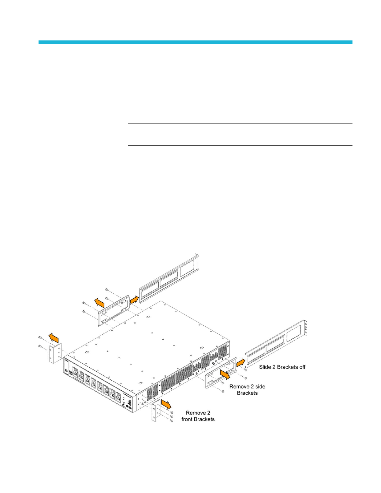
Remove rack brackets from the instrument
Prerequisite: Wear an anti-static wrist strap connected to the instrument chassis
while doing this conversion.
1. Remove all cables from the front and rear of the instrument, including the
power cable.
2. Position the instrument on its bottom, with the front facing you.
3. Remove the three screws from the rack mounting bracket at the right-front of
the instrument and remove the bracket.
MSO58LP, LPD64 Bench Conversion Kit Instructions 3
Page 10

Installation instructions
4. Remove the three screws from the rack mounting bracket at the left-front of
the instrument and remove the bracket.
5. If installed, remove both rack mount slides by sliding them to the rear of the
instrument until they are off of the chassis brackets.
6. Remove the four screws from the rack chassis bracket at the right of the
instrument and remove the bracket.
7. Remove the four screws from the rack chassis bracket at the left of the
instrument and remove the bracket.
NOTE. Keep all the screws and rack hardware together in a bag in case you
need to install the instrument in a rack at a future time.
Install the handle and feet
Prerequisite: Wear an anti-static wrist strap connected to the instrument chassis
while doing this conversion.
WARNING. Use only the hardware supplied with the Bench Conversion Kit. Use
of other parts or screws may result in damage to the instrument or injury to the
installer.
The kit has two types of screws to attach the handle and feet:
■
Use the four flathead Torx T-20 screws to attach the handle parts.
■
Use the four round head Torx T-20 Torx screws to attach the bottom feet.
1. Attach the handle to the right side of the instrument:
a. Position the instrument on its bottom, with the front facing you.
4 MSO58LP, LPD64 Bench Conversion Kit Instructions
Page 11

Installation instructions
b. Attach one handle spacer (407-5992-xx), one end of the handle
(367-0603-xx), and one handle top cap (407-5991-xx) to the right side of
the instrument, using two 10-32 flathead Torx T-20 screws (211-1645xx). Tighten to 2.2 N·m.
c. Attach one handle spacer (407-5992-xx), the other end of the handle
(367-0603-xx), and one handle top cap (407-5991-xx) to the instrument
using the other two 10-32 flathead Torx T-20 screws (211-1645-xx).
Tighten to 2.2 N·m.
2. Attach the feet to the bottom of the instrument:
a. Position the instrument on its top side, with the front facing you.
b. Place a stationary foot at each of the four foot locations near the corners
of the bottom plate. Each foot has two alignment pins that align the foot
onto the chassis. Position the feet so that the flat side of the foot faces the
front of the instrument.
c. Use a T-20 Torx screwdriver to attach each stationary foot with one
8-32 round head Torx screw (211-1315-xx). Tighten to 1.3 N·m.
d. Insert one foot cushion into each stationary foot screw hole, with the
small side tabs end first. Press down on the cushion until the foot cushion
stops and locks into place.
3. Turn over the instrument onto the feet and position the instrument on the
bench workspace.
MSO58LP, LPD64 Bench Conversion Kit Instructions 5
Page 12

Installation instructions
4. Connect power cord, signal probes, and cables as required for your
measurement needs.
WARNING. For proper cooling, keep both sides of the instrument clear of
obstructions for 2 inches (51 mm).
6 MSO58LP, LPD64 Bench Conversion Kit Instructions
 Loading...