

Page 1

5 Series B Mixed Signal Oscilloscopes
MSO54B, MSO56B, MSO58B
Quick Start Manual
: The servicing instructions are for use by qualified personnel only. To avoid personal injury, do not perform any servicing unless you are qualified
Warning
to do so. Refer to all safety summaries prior to performing service.
Supports Product Firmware Version 1.36 and above
Register now!
Click the following link to protect your product.
www.tek.com/register
*P077172300*
077-1723-00
Page 2

Copyright © Tektronix. All rights reserved. Licensed software products are owned by Tektronix or its subsidiaries or suppliers, and are
protected by national copyright laws and international treaty provisions. T
and pending. Information in this publication supersedes that in all previously published material. Specifications and price change privileges
reserved.
ektronix products are covered by U.S. and foreign patents, issued
TEKTRONIX and TEK are registered trademarks of T
ektronix, Inc.
Contacting Tektronix
Tektronix, Inc.
14150 SW Karl Braun Drive
P.O. Box 500
Beaverton, OR 97077
USA
For product information, sales, service, and technical support:
• In North America, call 1-800-833-9200.
• Worldwide, visit to www.tek.com find contacts in your area.
Page 3

Warranty
Warranty
Tektronix warrants that this product will be free from defects in materials and workmanship for a period of one (1) year from the date of
shipment. If any such product proves defective in materials or workmanship during this warranty period, Tektronix, at its option, either will
repair the defective product without charge for parts and labor, or will provide a replacement in exchange for the defective product. Parts,
modules and replacement products used by Tektronix for warranty work may be new or reconditioned to like new performance. All replaced
parts, modules and products become the property of Tektronix.
In order to obtain service under this warranty, Customer must notify Tektronix of the defect before the expiration of the warranty period
and make suitable arrangements for the performance of service. Customer shall be responsible for packaging and shipping the defective
product to the service center designated by Tektronix, with shipping charges prepaid. Tektronix shall pay for the return of the product to
Customer if the shipment is to a location within the country in which the Tektronix service center is located. Customer shall be responsible
for paying all shipping charges, duties, taxes, and any other charges for products returned to any other locations.
This warranty shall not apply to any defect, failure or damage caused by improper use or improper or inadequate maintenance and care.
Tektronix shall not be obligated to furnish service under this warranty a) to repair damage resulting from attempts by personnel other
than Tektronix representatives to install, repair or service the product; b) to repair damage resulting from improper use or connection to
incompatible equipment; c) to repair any damage or malfunction caused by the use of non-Tektronix supplies; or d) to service a product
that has been modified or integrated with other products when the effect of such modification or integration increases the time or difficulty
of servicing the product.
THIS WARRANTY IS GIVEN BY TEKTRONIX WITH RESPECT TO THE PRODUCT IN LIEU OF ANY OTHER WARRANTIES, EXPRESS
OR IMPLIED. TEKTRONIX AND ITS VENDORS DISCLAIM ANY IMPLIED WARRANTIES, INCLUDING WITHOUT LIMITATION ANY
IMPLIED WARRANTIES OF NON-INFRINGEMENT, SATISFACTORY QUALITY, MERCHANTABILITY OR FITNESS FOR A PARTICULAR
PURPOSE. TEKTRONIX' RESPONSIBILITY TO REPAIR OR REPLACE DEFECTIVE PRODUCTS IS THE SOLE AND EXCLUSIVE
REMEDY PROVIDED TO THE CUSTOMER FOR BREACH OF THIS WARRANTY. TEKTRONIX AND ITS VENDORS WILL NOT BE
LIABLE FOR ANY INDIRECT, SPECIAL, PUNITIVE, INCIDENTAL, OR CONSEQUENTIAL DAMAGES IRRESPECTIVE OF WHETHER
TEKTRONIX OR THE VENDOR HAS ADVANCE NOTICE OF THE POSSIBILITY OF SUCH DAMAGES.
[W2 – 15AUG04]
5 Series B Mixed Signal Oscilloscopes MSO54B, MSO56B, MSO58B Quick Start Manual 3
Page 4

Documentation
Documentation
Review the following user documents before installing and using your instrument. These documents provide important operating
information.
Product documentation
The following table lists the primary product specific documentation available for your product. These and other user documents are
available for download from www.tek.com. Other information, such as demonstration guides, technical briefs, and application notes, can
also be found at www.tek.com.
Document Content
Help In-depth operating information for the product. Available from the
Help button in the product UI and as a downloadable PDF on
www
.tek.com.
Quick Start User Manual Introduction to product hardware and software, installation
instructions, turn on, and basic operating information.
Specifications and Performance V
Programmer Manual Commands for remotely controlling the instrument.
Declassification and Security Instructions Information about the location of memory in the instrument.
Service Manual Replaceable parts list, theory of operations, and repair and replace
Upgrade Instructions Product upgrade installation information.
Rackmount Kit Instructions Installation information for assembling and mounting an instrument
erification Technical Reference Instrument specifications and performance verification instructions
for testing instrument performance.
Instructions for declassifying and sanitizing the instrument.
procedures for servicing an instrument.
using a specific rackmount.
How to find your product documentation
1. Go to www.tek.com
2. Click Download in the green sidebar on the right side of the screen.
3. Select Manuals as the Download Type, enter your product model, and click Search.
4. View and download your product manuals. You can also click the Product Support Center and Learning Center links on the page for
more documentation.
.
5 Series B Mixed Signal Oscilloscopes MSO54B, MSO56B, MSO58B Quick Start Manual 4
Page 5

Table of Contents
Table of Contents
Warranty........................................................................................................................................................................................3
Documentation..............................................................................................................................................................................4
Important safety information..........................................................................................................................................................7
General safety summary........................................................................................................................................................7
To avoid fire or personal injury........................................................................................................................................7
Probes and test leads..................................................................................................................................................... 8
Service safety summary.........................................................................................................................................................9
Terms in this manual............................................................................................................................................................ 10
Terms on the product........................................................................................................................................................... 10
Symbols on the product....................................................................................................................................................... 10
Compliance information...............................................................................................................................................................11
EMC compliance.................................................................................................................................................................. 11
Safety compliance................................................................................................................................................................11
Environmental compliance...................................................................................................................................................12
Preface........................................................................................................................................................................................13
Key features.........................................................................................................................................................................13
Installing your instrument............................................................................................................................................................ 14
Check shipped accessories................................................................................................................................................. 14
Safely rotate the handle.......................................................................................................................................................14
Operating requirements....................................................................................................................................................... 15
Input signal requirements.....................................................................................................................................................15
Secure (lock) the instrument................................................................................................................................................16
Powering the instrument...................................................................................................................................................... 16
Check that the instrument passes power-on self tests........................................................................................................ 17
Connecting probes to the instrument...................................................................................................................................17
Rackmount option information............................................................................................................................................. 18
Getting acquainted with your instrument ....................................................................................................................................19
Front panel controls and connectors....................................................................................................................................19
Rear panel connections....................................................................................................................................................... 23
User interface.......................................................................................................................................................................24
User interface elements.......................................................................................................................................................26
Badges.................................................................................................................................................................................28
Configuration menus............................................................................................................................................................36
Zoom user interface.............................................................................................................................................................37
Using the touch screen interface for common tasks............................................................................................................ 38
Configure the instrument.............................................................................................................................................................40
Set the time zone and clock readout format........................................................................................................................ 40
Download and install the latest instrument firmware............................................................................................................40
Run Signal Path Compensation (SPC)................................................................................................................................41
Compensate the TPP Series probes................................................................................................................................... 41
Connect to a network (LAN).................................................................................................................................................42
Operating basics......................................................................................................................................................................... 44
Add a channel waveform to the display............................................................................................................................... 44
Configure channel or waveform settings..............................................................................................................................45
5 Series B Mixed Signal Oscilloscopes MSO54B, MSO56B, MSO58B Quick Start Manual 5
Page 6

Table of Contents
Autoset to quickly display a waveform................................................................................................................................. 46
How to trigger on a signal.................................................................................................................................................... 47
Set the acquisition mode......................................................................................................................................................48
Set Horizontal parameters .................................................................................................................................................. 48
Add a math, reference, or bus waveform.............................................................................................................................49
Add a measurement.............................................................................................................................................................50
Configure a measurement................................................................................................................................................... 52
Add a plot of a measurement...............................................................................................................................................53
Add a Search....................................................................................................................................................................... 54
Delete a Measurement or Search badge.............................................................................................................................56
Change waveform view settings.......................................................................................................................................... 56
Display and configure cursors..............................................................................................................................................57
Remote access from a Web browser...................................................................................................................................59
Connect the oscilloscope to a PC using a USB cable......................................................................................................... 60
Mainten
ance................................................................................................................................................................................61
Inspection and cleaning....................................................................................................................................................... 61
Exterior cleaning (other than display)........................................................................................................................... 61
Flat panel display cleaning........................................................................................................................................... 61
Service the instrument......................................................................................................................................................... 62
Returning the instrument for service.................................................................................................................................... 62
Index........................................................................................................................................................................................... 63
5 Series B Mixed Signal Oscilloscopes MSO54B, MSO56B, MSO58B Quick Start Manual 6
Page 7

Important safety information
Important safety information
This manual contains information and warnings that must be followed by the user for safe operation and to keep the product in a safe
condition.
To safely perform service on this product, see the Service safety summary that follows the General safety summary.
General safety summary
Use the product only as specified. Review the following safety precautions to avoid injury and prevent damage to this product or any
products connected to it. Carefully read all instructions. Retain these instructions for future reference.
This product shall be used in accordance with local and national codes.
For correct and safe operation of the product, it is essential that you follow generally accepted safety procedures in addition to the safety
precautions specified in this manual.
The product is designed to be used by trained personnel only.
Only qualified personnel who are aware of the hazards involved should remove the cover for repair, maintenance, or adjustment.
Before use, always check the product with a known source to be sure it is operating correctly.
This product is not intended for detection of hazardous voltages.
Use personal protective equipment to prevent shock and arc blast injury where hazardous live conductors are exposed.
While using this product, you may need to access other parts of a larger system. Read the safety sections of the other component manuals
for warnings and cautions related to operating the system.
When incorporating this equipment into a system, the safety of that system is the responsibility of the assembler of the system.
To avoid fire or personal injury
Use proper power cord.
Use only the power cord specified for this product and certified for the country of use.
Ground the product.
This product is grounded through the grounding conductor of the power cord. To avoid electric shock, the grounding conductor must be
connected to earth ground. Before making connections to the input or output terminals of the product, ensure that the product is properly
grounded. Do not disable the power cord grounding connection.
Power disconnect.
The power cord disconnects the product from the power source. See instructions for the location. Do not position the equipment so that it is
difficult to operate the power cord; it must remain accessible to the user at all times to allow for quick disconnection if needed.
Connect and disconnect properly.
Do not connect or disconnect probes or test leads while they are connected to a voltage source.
Use only insulated voltage probes, test leads, and adapters supplied with the product, or indicated by Tektronix to be suitable for the
product.
Observe all terminal ratings.
To avoid fire or shock hazard, observe all rating and markings on the product. Consult the product manual for further ratings information
before making connections to the product.
5 Series B Mixed Signal Oscilloscopes MSO54B, MSO56B, MSO58B Quick Start Manual 7
Page 8

Important safety information
Do not exceed the Measurement Category (CAT) rating and voltage or current rating of the lowest rated individual component of a product,
probe, or accessory
Do not apply a potential to any terminal, including the common terminal, that exceeds the maximum rating of that terminal.
Do not float the common terminal above the rated voltage for that terminal.
The measuring terminals on this product are not rated for connection to Category III or IV circuits.
. Use caution when using 1:1 test leads because the probe tip voltage is directly transmitted to the product.
Do not operate without covers.
Do not operate this product with covers or panels removed, or with the case open. Hazardous voltage exposure is possible.
A
void exposed circuitry.
Do not touch exposed connections and components when power is present.
Do not operate with suspected failures.
If you suspect that there is damage to this product, have it inspected by qualified service personnel.
Disable the product if it is damaged. Do not use the product if it is damaged or operates incorrectly. If in doubt about safety of the product,
turn it off and disconnect the power cord. Clearly mark the product to prevent its further operation.
Before use, inspect voltage probes, test leads, and accessories for mechanical damage and replace when damaged. Do not use probes or
test leads if they are damaged, if there is exposed metal, or if a wear indicator shows.
Examine the exterior of the product before you use it. Look for cracks or missing pieces.
Use only specified replacement parts.
Do not operate in wet/damp conditions.
Be aware that condensation may occur if a unit is moved from a cold to a warm environment.
Do not operate in an explosive atmosphere.
Keep product surfaces clean and dry.
Remove the input signals before you clean the product.
Provide proper ventilation.
Refer to the installation instructions in the manual for details on installing the product so it has proper ventilation.
Slots and openings are provided for ventilation and should never be covered or otherwise obstructed. Do not push objects into any of the
openings.
Provide a safe working environment
Always place the product in a location convenient for viewing the display and indicators.
Avoid improper or prolonged use of keyboards, pointers, and button pads. Improper or prolonged keyboard or pointer use may result in
serious injury.
Be sure your work area meets applicable ergonomic standards. Consult with an ergonomics professional to avoid stress injuries.
Use care when lifting and carrying the product. This product is provided with a handle or handles for lifting and carrying.
Use only the Tektronix rackmount hardware specified for this product.
Probes and test leads
Before connecting probes or test leads, connect the power cord from the power connector to a properly grounded power outlet.
5 Series B Mixed Signal Oscilloscopes MSO54B, MSO56B, MSO58B Quick Start Manual 8
Page 9

Important safety information
Keep fingers behind the protective barrier, protective finger guard, or tactile indicator on the probes. Remove all probes, test leads and
accessories that are not in use.
Use only correct Measurement Category (CA
any measurement.
T), voltage, temperature, altitude, and amperage rated probes, test leads, and adapters for
Beware of high voltages.
Understand the voltage ratings for the probe you are using and do not exceed those ratings. Two ratings are important to know and
understand:
•
The maximum measurement voltage from the probe tip to the probe reference lead.
• The maximum floating voltage from the probe reference lead to earth ground.
These two voltage ratings depend on the probe and your application. Refer to the Specifications section of the manual for more
information.
Warning: To prevent electrical shock, do not exceed the maximum measurement or maximum floating voltage for the oscilloscope
input BNC connector
, probe tip, or probe reference lead.
Connect and disconnect properly.
Connect the probe output to the measurement product before connecting the probe to the circuit under test. Connect the probe reference
lead to the circuit under test before connecting the probe input. Disconnect the probe input and the probe reference lead from the circuit
under test before disconnecting the probe from the measurement product.
De-energize the circuit under test before connecting or disconnecting the current probe.
Connect the probe reference lead to earth ground only.
Do not connect a current probe to any wire that carries voltages or frequencies above the current probe voltage rating.
Inspect the probe and accessories.
Before each use, inspect probe and accessories for damage (cuts, tears, or defects in the probe body, accessories, or cable jacket). Do
not use if damaged.
Ground-referenced oscilloscope use.
Do not float the reference lead of this probe when using with ground-referenced oscilloscopes. The reference lead must be connected to
earth potential (0 V).
Floating measurement use.
Do not float the reference lead of this probe above the rated float voltage.
Service safety summary
The
Service safety summary section contains additional information required to safely perform service on the product. Only qualified
personnel should perform service procedures. Read this Service safety summary and the General safety summary before performing any
service procedures.
To avoid electric shock.
Do not touch exposed connections.
Do not service alone.
Do not perform internal service or adjustments of this product unless another person capable of rendering first aid and resuscitation is
present.
5 Series B Mixed Signal Oscilloscopes MSO54B, MSO56B, MSO58B Quick Start Manual 9
Page 10

Disconnect power.
Important safety information
To avoid electric shock, switch of
panels, or opening the case for servicing.
f the product power and disconnect the power cord from the mains power before removing any covers or
Use care when servicing with power on.
Dangerous voltages or currents may exist in this product. Disconnect power, remove battery (if applicable), and disconnect test leads
before removing protective panels, soldering, or replacing components.
Verify safety after repair.
Always recheck ground continuity and mains dielectric strength after performing a repair.
Terms in this manual
These terms may appear in this manual:
Warning: Warning statements identify conditions or practices that could result in injury or loss of life.
CAUTION: Caution statements identify conditions or practices that could result in damage to this product or other property.
T
erms on the product
These terms may appear on the product:
• DANGER indicates an injury hazard immediately accessible as you read the marking.
WARNING indicates an injury hazard not immediately accessible as you read the marking.
•
• CAUTION indicates a hazard to property including the product.
Symbols on the product
When this symbol is marked on the product, be sure to consult the manual to find out the nature of the potential
hazards and any actions which have to be taken to avoid them. (This symbol may also be used to refer the user to
ratings in the manual.)
The following symbols(s) may appear on the product.
5 Series B Mixed Signal Oscilloscopes MSO54B, MSO56B, MSO58B Quick Start Manual 10
Page 11

Compliance information
Compliance information
This section lists the EMC, safety, and environmental standards with which the instrument complies. This product is intended for use by
professionals and trained personnel only; it is not designed for use in households or by children.
Questions about compliance information may be directed to the following address:
Tektronix, Inc.
PO Box 500, MS 19-045
Beaverton, OR 97077, USA
tek.com
EMC compliance
These products are Class A instruments and are not intended to be used in a residential environment.
Safety compliance
This section lists the safety compliance information.
Equipment type
T
est and measuring equipment.
Safety class
Class 1 – grounded product.
Safety certification of plug-in or VXI modules
The safety certification is valid only when installed in an appropriately approved (by a USA NRTL or a Canada Certified Organization)
mainframe.
Pollution degree description
A measure of the contaminants that could occur in the environment around and within a product. Typically the internal environment inside a
product is considered to be the same as the external. Products should be used only in the environment for which they are rated.
Pollution Degree 1. No pollution or only dry, nonconductive pollution occurs. Products in this category are generally encapsulated,
•
hermetically sealed, or located in clean rooms.
• Pollution Degree 2. Normally only dry, nonconductive pollution occurs. Occasionally a temporary conductivity that is caused by
condensation must be expected. This location is a typical office/home environment. Temporary condensation occurs only when the
product is out of service.
• Pollution Degree 3. Conductive pollution, or dry, nonconductive pollution that becomes conductive due to condensation. These are
sheltered locations where neither temperature nor humidity is controlled. The area is protected from direct sunshine, rain, or direct
wind.
• Pollution Degree 4. Pollution that generates persistent conductivity through conductive dust, rain, or snow. Typical outdoor locations.
Pollution degree rating
Pollution Degree 2 (as defined in IEC 61010-1). Note: Rated for indoor, dry location use only.
IP rating
IP20 (as defined in IEC 60529).
5 Series B Mixed Signal Oscilloscopes MSO54B, MSO56B, MSO58B Quick Start Manual 11
Page 12

Compliance information
Measurement and overvoltage category descriptions
Measurement terminals on this product may be rated for measuring mains voltages from one or more of the following categories (see
specific ratings marked on the product and in the manual).
• Measurement Category II. For measurements performed on circuits directly connected to the low-voltage installation.
Measurement Category III. For measurements performed in the building installation.
•
• Measurement Category IV. For measurements performed at the source of low-voltage installation.
Note: Only mains power supply circuits have an overvoltage category rating. Only measurement circuits have a measurement
category rating. Other circuits within the product do not have either rating.
Mains overvoltage category rating
Overvoltage Category II (as defined in IEC 61010-1)
Environmental compliance
This section provides information about the environmental impact of the product.
Product end-of-life handling
Observe the following guidelines when recycling an instrument or component:
Equipment recycling Production of this equipment required the extraction and use of natural resources. The equipment may
contain substances that could be harmful to the environment or human health if improperly handled at the
product’s end of life. T
natural resources, we encourage you to recycle this product in an appropriate system that will ensure that
most of the materials are reused or recycled appropriately.
This symbol indicates that this product complies with the applicable European Union requirements according to Directives
2012/19/EU and 2006/66/EC on waste electrical and electronic equipment (WEEE) and batteries. For information about
recycling options, check the Tektronix W
Battery recycling This product contains a small installed lithium metal button cell. Please properly dispose of or recycle the
cell at its end of life according to local government regulations.
Perchlorate materials This product contains one or more type CR lithium batteries. According to the state of California, CR
lithium batteries are classified as perchlorate materials and require special handling. See www
hazardouswaste/perchlorate for additional information.
T
ransporting batteries
The small lithium primary cell contained in this equipment does not exceed 1 gram of lithium metal content per cell.
The cell type has been shown by the manufacturer to comply with the applicable requirements of the UN Manual of Tests and Criteria
Part III, Sub-section 38.3. Consult your carrier to determine which lithium battery transportation requirements are applicable to your
configuration, including to its re-packaging and re-labeling, prior to reshipment of the product by any mode of transport.
o avoid release of such substances into the environment and to reduce the use of
eb site (www.tek.com/productrecycling).
.dtsc.ca.gov/
5 Series B Mixed Signal Oscilloscopes MSO54B, MSO56B, MSO58B Quick Start Manual 12
Page 13

Preface
Preface
This manual provides product safety and compliance information, describes how to connect and power on the oscilloscope, and introduces
the instrument features, controls and basic operations. See the product Help document for more detailed information.
Key features
Welcome to the 5 Series B Mixed Signal Oscilloscope. The 5 Series B MSO includes FlexChannel® inputs, enabling you to efficiently and
cost-effectively perform mixed signal debugging on virtually any design.
• Bandwidths from 350 MHz to 2 GHz
• 4, 6, or 8 channels with FlexChannel® inputs
• Each FlexChannel input is dual-purpose, letting you connect either an analog probe (TekVPI® or BNC) or an eight-channel digital
probe (the TLP058 FlexChannel Logic Probe)
• Each FlexChannel can display 8 digital channels (with TLP058), an analog waveform, a spectrum view, or both an analog and spectral
view of the same channel at the same time with independent controls for each view
• FlexChannel inputs are compatible with TekVPI® probes
• Large 15.6” HD (1920 x 1080 pixel) capacitive touch-screen display
• User interface designed to optimize touch screen use and quickly access key settings
• Stacked mode places each channel or waveform in its own horizontal 'slice' on the screen, allowing for cleaner signal viewing and
measuring
• Maximum 6.25 GS/s sample rate
• 62.5 M points record length on all channels (optional 125 M, 250 M, and 500 M record lengths available)
• >500,000 waveforms/second maximum waveform capture rate
• Spectrum View enables simple, intuitive frequency domain analysis, independent of time domain controls, to show a spectral trace for
each channel
• No set limit on the number of math, reference, and bus waveforms you can display (the number of waveforms depends on available
system memory)
• Integrated optional features include a 100 MHz arbitrary function generator (AFG), and a DVM and trigger frequency counter
• Optional serial triggering features enable you to isolate protocol-level events of interest in common aerospace, audio, automotive,
computer, and embedded serial buses. See the Serial bus and trigger options topic in the instrument Help, or the Serial Triggering and
Analysis Applications Datasheet (Tektronix part number 48W-61353-X) for more information
• Power, DPM, IMDA, and Jitter options provide additional measurement and analysis functions. See the Advanced Power Analysis,
DPM Analysis, and Advanced Jitter Analysis Help topics.
5 Series B Mixed Signal Oscilloscopes MSO54B, MSO56B, MSO58B Quick Start Manual 13
Page 14

Installing your instrument
Check shipped accessories
Installing your instrument
Make sure that you received everything you ordered. If anything is missing, contact T
1-800-833-9200. Worldwide, visit www.tek.com to find contacts in your area.
Check the packing list that came with your instrument to verify that you have received all standard accessories and ordered items. If you
purchased factory installed options such as a Serial Bus and Triggering option, or the Power measurements option, tap Help > About to
confirm that the options are listed in the Installed Options table.
Item Quantity Tektronix part number
5 Series B MSO Installation and Safety Manual 1 071-3773-xx
TPP0500B Passive Voltage Probe (500 MHz bandwidth). Shipped with 350 MHz
and 500 MHz models.
TPP1000 Passive Voltage Probe (1 GHz bandwidth). Shipped with 1 GHz and 2
GHz models.
Front cover 1 200-5406-xx
Accessory pouch (attached to front cover) 1 016-2106-xx
Mouse (wired with USB connector) 1 119-7054-xx
Power cord 1 Depends on region
Calibration certificate 1 N/A
Report of factory installed licenses 1 N/A
ektronix Customer Support. In North America, call
One per channel TPP0500B
One per channel TPP1000
Safely rotate the handle
Use the correct process to eliminate the chance of pinching your thumb or rear-panel-connected cables while rotating the handle.
Warning: Hold the top of the handle to rotate the handle on the instrument. Do not hold the handle from the sides and rotate, as
this can pinch the base of your thumb between the handle and the case.
CAUTION: If you have routed any cables between the handle and the case, be careful when rotating the handle so that you do
not pinch the cables.
5 Series B Mixed Signal Oscilloscopes MSO54B, MSO56B, MSO58B Quick Start Manual 14
Page 15

Installing your instrument
Operating requirements
Use the instrument within the required operating temperature, power, altitude, and signal input voltage ranges to provide the most accurate
measurements and safe instrument operation.
able 1: Environment requirements
T
Characteristic Description
Operating temperature 0 °C to +50 °C (+32 °F to +122 °F)
For proper cooling, keep the sides and rear of the instrument clear of obstructions for 2 inches (51 mm).
Operating humidity 5% to 90% relative humidity (% RH) up to +40 °C (+104 °F), non-condensing.
5% to 55% RH above +40 °C up to +50 °C (+104 °F to +122 °F), non-condensing.
5% to 90% RH at temperatures up to +60°C (+140°F), non-condensing, and as limited by a maximum
wet-bulb temperature of +39°C (+102°F).
Operating altitude Up to 3000 meters (9842 feet)
Table 2: Power requirements
Characteristic Description
Power source voltage 100 V - 240 V
Power source frequency 50/60 Hz, 100-240 V
400 Hz, 115 V
Power consumption 400 W maximum
, ±10%, single phase
AC RMS
Input signal requirements
Keep the input signals within allowed limits to ensure the most accurate measurements and prevent damage to the analog and digital
probes or instrument.
Make sure that input signals connected to the instrument are within the following requirements.
Input Description
Analog input channels, 1 MΩ setting,
maximum input voltage at BNC
Analog input channels, 50 Ω setting,
maximum input voltage at BNC
Digital input channels, maximum input
voltage range at digital inputs
Ref In maximum input voltage at BNC (rear
panel)
Aux In trigger input ±5 V
300 V
RMS
Measurement Category II
5 V
, at 100 mV/div, with peaks
RMS
Measurement Category II
Observe probe ratings
TLP058; ±42 V
7 V
PP
RMS
P
≤ ±20 V (Pulse Width ≤200 us)
5 Series B Mixed Signal Oscilloscopes MSO54B, MSO56B, MSO58B Quick Start Manual 15
Page 16

Installing your instrument
Secure (lock) the instrument
Lock an instrument to a test bench or equipment rack to prevent property loss.
Attach a standard laptop security lock to the rear panel of the instrument, to secure the instrument to a workbench, rack, or other location.
Powering the instrument
Use this procedure to connect the instrument to line power and power on and off the instrument. Always connect the instrument to AC
power using the power cord that shipped with the instrument.
Prerequisite: Use the AC power cord that shipped with your instrument.
1. Connect the supplied power cord to the instrument power connector on the back of the instrument.
Figure 1: Power cord connector and power standby switch
2. Connect the power cord to an appropriate AC mains source.
Power is supplied to the power supply and some other boards whenever the AC power cord is connected to a live mains circuit, putting
the instrument in standby mode.
3. Push the front panel power button to power the instrument on and off.
The power button color indicates instrument power states:
•
Unlit – no AC power applied
• Yellow – standby mode
• Blue – powered on
4. To completely remove power from the instrument, disconnect the power cord.
5. To transport the instrument with its power cord, flip out the power cord supports on the upper edge of the rear panel and wrap the
power cord around the supports.
5 Series B Mixed Signal Oscilloscopes MSO54B, MSO56B, MSO58B Quick Start Manual 16
Page 17

Installing your instrument
Check that the instrument passes power-on self tests
Power-on self tests verify that all instrument modules are working correctly after power up.
Procedure
1. Power on the instrument and wait until the instrument screen appears.
2. Select Utility > Self Test
3. Check that the status of all power-on self tests are Passed.
If one or more power-on self tests shows Failed:
1. Power cycle the instrument.
2. Select Utility > Self Test. If one or more power-on self tests still shows Failed, contact Tektronix Customer Support.
from the top-edge Menu bar to open the Self Test configuration menu.
Connecting probes to the instrument
Probes connect the instrument to your device under test (DUT). Use a probe that best matches your signal measurement needs.
Connect TPP Series, TekVPI+, TekVPI, or other supported Tektronix analog probes by pushing them into a FlexChannel connector. The
probe base latch locks with a 'click' when the probe is fully seated.
TekVPI probes automatically set the channel input parameters for that probe (bandwidth, attenuation, termination, and so on). If a probe
has a Menu button, push that button to open an on-screen configuration menu. Follow instructions provided with active probes to set their
parameters (auto zero, degauss, and so on).
To connect a TLP058 FlexChannel Logic Probe:
1. Move the locking lever to the unlocked position, then let go to reset locking lever to the center position.
2. Insert the probe into a FlexChannel connector until fully seated and the lock mechanism clicks.
3. Move the locking lever to the locked position. The status light should be a solid green.
4. To disconnect the TLP058 probe, move and hold the locking lever at the unlocked position and pull out the probe. Do not pull on the
ribbon cable while removing the probe.
Connect a BNC probe or cable by pushing it onto a channel BNC bayonet connector and turn the lock mechanism clockwise until it locks.
Note: Connecting a probe does not automatically enable that channel (make it active). Use the instrument controls or
programmatic interface to turn on a channel and open its configuration menu to verify or change probe or cable settings
(bandwidth, attenuation, termination and so on).
5 Series B Mixed Signal Oscilloscopes MSO54B, MSO56B, MSO58B Quick Start Manual 17
Page 18

Rackmount option information
An optional rackmount kit lets you install the oscilloscope in standard equipment racks.
Please refer to your product's datasheet at www.tek.com for more information on rackmount options.
Installing your instrument
5 Series B Mixed Signal Oscilloscopes MSO54B, MSO56B, MSO58B Quick Start Manual 18
Page 19

Getting acquainted with your instrument
Front panel controls and connectors
Getting acquainted with your instrument
The front panel controls provide direct access to key instrument settings such as vertical, horizontal, trigger
connectors are where you input signals with probes or cables, or insert USB devices.
Note: Refer to the instrument help for detailed information on using the controls to display waveforms and take measurements.
, cursors, and zoom. The
Figure 2: 5 Series B MSO controls
1. Acquisition
• Run/Stop starts and stops waveform acquisition. The button color indicates the acquisition status (green = running and
acquiring; red = stopped). When stopped, the oscilloscope shows waveforms from the last completed acquisition. The Run/Stop
button on the screen also shows the acquisition status.
• Cursors
or on a cursor bar (line), to open the configuration menu to set cursor types and functionality.
• Fast Acq™ enables or disables the fast acquisition mode. FastAcq provides high-speed waveform capture that reduces the dead
time between waveform acquisitions, enabling the capture and display of transient events such as glitches and runt pulses. It
is helpful in finding elusive signal anomalies. Fast acquisition mode can also display waveform phenomena at an intensity that
reflects their rate of occurrence.
• Single/Seq enables making a single waveform acquisition, or a specified number of acquisitions (as set in the Acquisition
configuration menu). Pushing Single/Seq turns off Run/Stop mode and takes a single acquisition. The button color indicates the
acquisition status (quick green flash = single acquisition acquired; solid green = waiting for trigger event). Pushing Single/Seq
again takes another single acquisition.
and Cursors controls:
button turns screen cursors on or off. Use the Multipurpose knobs to move the cursors. Double-tap the cursor readouts,
5 Series B Mixed Signal Oscilloscopes MSO54B, MSO56B, MSO58B Quick Start Manual 19
Page 20

Getting acquainted with your instrument
• High Res applies unique finite impulse response (FIR) filters based on the current sample rate. This FIR filter maintains
the maximum bandwidth possible for that sample rate while rejecting aliasing. The filter removes noise from the oscilloscope
amplifiers and ADC above the usable bandwidth for the selected sample rate.
the trigger and storage, reduces trigger jitter and enables using Fast Acq
High Res mode also guarantees at least 12 bits of vertical resolution. The number of bits of resolution is displayed in the
Acquisition badge at the bottom of the screen. The Horizontal badge also updates to show the sample rate and record length
settings while in High Res mode.
• Clear deletes the current acquisitions and measurement values from memory.
2. Multipurpose knobs: The Multipurpose knobs A and B move cursors and set parameter values in configuration menu input fields.
Selecting an menu field that can use a Multipurpose knob assigns the indicated knob to change the value in that input field. The ring
around each knob lights when you can use that knob to do an action. Push a Multipurpose knob to enable the Fine mode for making
smaller increment changes. Push the knob again to exit Fine mode.
Implementation of the filter in hardware, ahead of
mode while in High Res mode.
3. Trigger controls:
• Force forces a trigger event at a random point in the waveform and captures the acquisition.
• Level sets the amplitude level that the signal must pass through to be considered a valid transition. The color of the
LED indicates the trigger source except for dual-level triggers.
The Level knob is disabled when the trigger type requires two level settings or other trigger qualifiers (set from the Trigger
configuration menu). Push the knob to set the threshold level to 50% of the peak-to-peak amplitude range of the signal.
• Slope sets the signal transition direction to detect for a trigger (low to high, high to low, or either direction). Push the button to
cycle through the selections. The Slope button is disabled when the trigger type requires other slope qualifiers (set from the
Trigger configuration menu).
• Mode sets how the instrument behaves in the absence or presence of a trigger event:
Level knob
5 Series B Mixed Signal Oscilloscopes MSO54B, MSO56B, MSO58B Quick Start Manual 20
Page 21

Getting acquainted with your instrument
• Auto trigger mode enables the instrument to acquire and display a waveform whether or not a trigger event occurs.
trigger event occurs, the instrument displays a stable waveform. If a trigger event does not occur, the instrument forces a
trigger event and acquisition and displays an unstable waveform.
• Normal trigger mode sets the instrument to acquire and display a waveform only when there is a valid trigger event. If
no trigger occurs, the last waveform record acquired remains on the display. If no last waveform exists, no waveform is
displayed.
4.
Vertical controls:
• Position moves the selected waveform (Channel, Math, Reference, Bus) and its graticule up or down on the screen. The color
of the Position knob indicates which waveform the knob is controlling.
peak-to-peak amplitude range of the signal.
• Scale sets the amplitude units per vertical graticule division of the selected waveform. The scale values are shown on the right
edge of the horizontal graticule lines, and are specific to the selected waveform in both Stacked or Overlay modes (in other
words, each waveform has its own unique vertical graticule settings regardless of display mode). The color of the Scale knob
indicates which waveform the knob is controlling.
• Channel buttons turn on (display), select, or turn off Channel, Math, Reference, or Bus waveforms. The number of channel
buttons depends on the instrument model. The buttons operate as follows:
Push the knob to set the threshold level to 50% of the
If a
• If the channel is not displayed, pushing a Channel button turns on that channel to the Waveform view.
• If the channel is on the screen and is not selected, pushing that channel's button selects that channel.
• If the channel is on the screen and is also selected, pushing that channel's button turns that channel off (removes it from
Waveform view).
• Math button adds or selects a Math waveform on the Waveform view.
• If no Math waveform exists, pushing the Math button adds a Math waveform to the Waveform view and opens the Math
configuration menu.
• If only one Math waveform is displayed, pushing the button turns off the Math waveform (removes it from Waveform view).
Push the button again to display the waveform.
• If two or more Math waveforms are displayed, pushing the button cycles through selecting each math waveform.
• Ref button adds or selects a Reference (saved) waveform on the Waveform view.
• If no Reference waveform exists, pushing the Ref button opens the Browse Waveform Files configuration menu. Navigate
to and select a waveform file (*.wfm) and tap Recall to load and display the reference waveform.
• If only one Reference waveform is displayed, pushing the button turns off the Reference waveform (removes it from the
Waveform View). Push the button again to display the waveform.
• If two or more Reference waveforms are displayed, pushing the button cycles through selecting each Reference waveform.
• Bus button adds or selects a bus waveform on the Waveform view.
• If no Bus waveform exists, pushing the Bus button adds a Bus waveform to the Waveform view and opens the Bus
configuration menu.
• If only one Bus waveform is displayed, pushing the button turns off the Bus waveform (removes it from Waveform view).
• If two or more Bus waveforms are displayed, pushing the button cycles through selecting each Bus waveform.
5. Horizontal controls:
5 Series B Mixed Signal Oscilloscopes MSO54B, MSO56B, MSO58B Quick Start Manual 21
Page 22

Getting acquainted with your instrument
• Position moves the waveform and graticule side to side on the screen (changing the trigger point position in the waveform
record). Push the knob to center the trigger event to the center graticule on the Waveform view
• Scale sets the time per major horizontal graticule division and samples/second parameters for the oscilloscope. Scale applies to
all waveforms. Push the knob to enable the Fine mode for making smaller increment changes. Push the knob again to exit Fine
mode.
• Zoom opens the Zoom mode. Push Zoom again to close zoom mode.
• Zoom knob (center knob) increases or decreases the area of the zoom box in the Zoom Waveform Overview, which in turn
controls the zoom amount of the waveforms shown in the main Zoom view.
• Pan knob (outer knob) moves the Zoom box left or right in the Zoom Waveform Overview, which in turn controls the part of the
waveform shown in the main Zoom view.
• Navigate (left and right arrow) buttons puts the oscilloscope in Zoom mode and positions the previous or next search point in the
waveform record to the center graticule of the Waveform view. There must be a Search badge present in the Results bar before
the Navigate function will operate. Press and hold a front panel navigate button to continue moving to the next search point in
that direction.
.
The front panel Navigate buttons can also be used for the Previous and Next button functions on measurement badges.
6. Miscellaneous controls:
• Touch Off turns touch screen capability off. The Touch Off button is lighted when the touch screen is turned off.
• Save is a one-push save operation that uses the current File > Save As settings to save screen shots (including open menus
and dialog boxes), waveform files, instrument settings, and so on.
• If a File > Save or File > Save As operation has occurred since the last instrument startup, pushing Save saves the file types
to the location last set in the Save As configuration menu.
• If no file save operation has occurred since the last instrument startup, pushing Save opens the Save As configuration menu.
Select a tab to select the type of file to save (Screen Capture, Waveform, and so on), set any associated parameters, and
where to save it, and select OK. The specified file or files are saved. The next time you push Save, the same type files are
saved.
• Screen Captures capture the entire screen, including most displayed configuration menus and dialog boxes.
• Default Setup restores the oscilloscope settings (horizontal, vertical, scale, position, and so on) to the factory default settings.
• Autoset automatically displays a stable waveform.
7. Ground and Probe Compensation connectors: The Ground and Probe Compensation connectors are located at the lower right side
of the instrument, near the front panel. The Ground connector (the small hole in the case) provides an electrically grounded (through
a resistor) connection point to attach an anti-static wrist strap, to reduce electrostatic damage (ESD) while you handle or probe the
DUT.
5 Series B Mixed Signal Oscilloscopes MSO54B, MSO56B, MSO58B Quick Start Manual 22
Page 23

Getting acquainted with your instrument
The Probe Compensation connections provide a ground connector (upper tab) and 1 kHz square wave source (lower tab) for
adjusting the high-frequency response of a passive probe (probe compensation). The oscilloscope uses this signal to automatically
compensate supported probes, including the ones that ship with the product.
8. USB Host ports (USB 3.0 and 2.0): USB ports are located at the lower right corner of the front panel, and on the rear panel.
Connect USB flash drives to which you can save or recall data (such as instrument software updates, waveforms, settings, and
screen captures), or connect peripheral devices such as a mouse or keyboard.
9. FlexChannel
probes, the TPL058 FlexChannel Logic Probe, and BNC cables. You connect most probes simply by pushing them into the connector
until the probe seats with a click.
probe connectors: FlexChannel connectors support all TekVPI+ and TekVPI measurement probes, BNC passive
10. Aux In auxiliary trigger input connector. A connector to which you can connect an external trigger input signal. Use the Aux In trigger
signal with the Edge trigger mode.
Rear panel connections
The rear panel connections supply power to the instrument and provide connectors for network, USB devices, video, reference signals,
and the AFG output.
1. Power cord connector. Use only the power cord specified for this product and certified for the country of use.
Ref In lets you connect a high-precision 10 MHz reference signal to the oscilloscope for more accurate measurements.
2.
3. AUX Out generates a signal transition on a trigger event, outputs a 10 MHz reference signal, or outputs a synchronization signal from
the AFG.
4. AFG Out is the signal output for the optional Arbitrary Function Generator (AFG) feature.
5. Video outputs (Display Port, VGA, and DVI-D) let you connect an external monitor or projector to show the instrument's graphical user
interface.
5 Series B Mixed Signal Oscilloscopes MSO54B, MSO56B, MSO58B Quick Start Manual 23
Page 24

Getting acquainted with your instrument
6. USB 3.0 Device port lets you connect to a PC to remotely control the instrument using USBTMC protocol.
USB Host ports let you connect a USB memory device, keyboard, or mouse.
7.
8.
LAN connector (RJ-45) connects the instrument to a 10/100/1000 Base-T local area network.
9. Security lock connector lets you use a standard PC/laptop lock cable to secure the instrument to a work bench or other location.
User interface
The touch screen user interface contains waveforms and plots, measurement readouts, and touch-based controls to access all
oscilloscope functions.
Note: Refer to the instrument help for detailed information on using the user interface to display waveforms and take
measurements.
1. The Menu bar provides menus for typical operations including:
•
Saving, loading, and accessing files
Undoing or redoing an action
•
• Setting oscilloscope display and measurement preferences
• Configuring network access
• Running self tests
• Erasing measurement and settings memory (TekSecure™)
• Loading option licenses
• Opening a Help viewer
2. The Waveform View area displays analog, digital, math, reference, bus, and trend waveforms. The waveforms include waveform
handles (identifiers), individual vertical graticule scale labels, and trigger position and level(s) indicators. You can set the Waveform
View to stack each waveform vertically in separate graticules, called 'slices' (the default mode, as shown in the previous image), or
overlay all the waveforms on the screen (traditional waveform view). See User interface elements on page 26.
You can also add Histogram, Spectral, Eye, and Measurement Results views (plots) for individual measurements. These plot views are
separate view windows that you can move on the screen by dragging their title bar to a new position.
5 Series B Mixed Signal Oscilloscopes MSO54B, MSO56B, MSO58B Quick Start Manual 24
Page 25

Getting acquainted with your instrument
3. The Results Bar contains controls for displaying cursors, adding callout, plots, and result tables to the screen, and add measurements
. T
to the Results bar
• The Cursors button displays on-screen cursors in the selected view. Touch and drag, or use the Multipurpose knobs, to move the
cursors. Double-tap on a cursor, or on the cursor readouts, to open a configuration menu to set cursor types and related functions.
• The Measure button opens a configuration menu from which to select and add measurements to the Results bar. Each
measurement you add has a separate badge. Double-tap a measurement badge to open its configuration menu.
• The Results Table button adds a Measurement or Bus Results table to the screen. The Measurement Results table displays all
measurements present in the Results bar. The Bus Results table displays bus decode information for displayed bus waveforms.
Each table is contained within its own view window, which can be moved within the display area.
• To remove a measurement, search or other badge from the Results Bar simply flick it off screen.
• The Callout button adds a Callout object to the selected view. Double-tap the Callout text to open a configuration menu to change
the type of callout, text and font characteristics. Drag any callout other than bookmark to any location on the oscilloscope screen
view. Bookmarks callout can only be added to waveviews and spectrum views.
• The Search button lets you detect and mark a waveform where specified events occur. Tap Search to open a Search configuration
menu and set the search conditions for analog and digital channels. You can add any number of searches to the same waveform or
to different waveforms. Search badges are added to the Results Bar.
• The Plot button adds an XY, XYZ, or Eye Diagram plot to the display. These plots are contained within their own window and can
be moved within the overall display area.
• The Measurement and Search badges show measurement and search results, and are displayed in the Results Bar. See
Badges on page 28. See Add a measurement on page 50. See Add a Search on page 54.
• The Zoom icon button at the up right of the Results Bar lets you to draw a box on the screen to zoom in on an area of interest,
drawing segments for mask testing, or drawing areas to define visual trigger conditions.
• The More... button at the up right of the Results Bar allows you to select Zoom, Visual trigger or Mask.
4. The Settings Bar contains System badges for setting Horizontal, Trigger, Acquisition, and Date/Time parameters; Inactive Channel
buttons to turn on channels; Add New Waveform buttons to add math, reference, and bus waveforms to the display; and Channel and
Waveform badges that let you configure the individual waveform parameters. Tap a channel or waveform button to add it to the screen
and display a badge. Double-tap a badge to open its configuration menu.
o remove a measurement, search or other badge from the Results Bar simply flick it off screen. The controls are:
See Badges on page 28.
5. Configuration Menus let you quickly change the parameters of the selected user interface item. You can open configuration menus by
double-tapping on badges, screen objects, or screen areas. See Configuration menus on page 36.
5 Series B Mixed Signal Oscilloscopes MSO54B, MSO56B, MSO58B Quick Start Manual 25
Page 26

Getting acquainted with your instrument
User interface elements
Each area of the user interface has a specific function that helps manage information or controls. This topic shows and describes the key
user interface elements.
1. The Waveform Record View is a graphical high-level view of the overall waveform record length, how much of the record is on the
screen (shown in brackets), the location of key time events including the trigger event, and the current position of waveforms cursors.
If you are displaying a Reference waveform that is shorter than the current acquisition record length, or you are changing the
horizontal time scale while the oscilloscope acquisition is stopped, the brackets change position to show the part of the waveform
record that is being viewed relative to the current acquisition total record length.
If cursors are active on a waveform, the Waveform Record View shows the relative cursor positions as small vertical dashed lines.
When in Zoom mode, the Waveform Record View is replaced with the Zoom Overview. See Zoom user interface on page 37.
2. The Expansion Point icon on the waveform view shows the center point around which the waveform expands and compresses when
changing horizontal settings.
3. The Trigger Position Indicator shows where the trigger event occurred in the waveform record. The trigger icon is displayed in the
waveform slice that is the trigger source.
5 Series B Mixed Signal Oscilloscopes MSO54B, MSO56B, MSO58B Quick Start Manual 26
Page 27

Getting acquainted with your instrument
4. The Zoom icon (in upper right corner of W
also turn on zoom mode and change the position and horizontal size of the Zoom Box.
5. The Trigger Level Indicator icon(s) shows the trigger level on the trigger source waveform. Some trigger types require two trigger
levels.
6. Measurement and Search badges show measurement and search results. See Badges
measurement on page 50.
7. The Results Bar Handle opens or closes the Results bar, to maximize waveform screen viewing when needed. To reopen the
Results bar, either tap the handle icon or swipe left from the right side of the display.
8. The System badges show global instrument settings (Horizontal, Trigger, Acquisition, Run/Stop status, and Date/Time). See
Badges on page 28.
9. The Inactive Channel buttons add channel waveforms to the Waveform view and add an associated Channel badge to the Settings
bar.
The Add New Math, Add New Ref, and Add New Bus buttons add the corresponding signal to the Waveform view, and add an
associated Waveform badge to the Settings bar. You can add any number of Math, Reference, and Bus waveforms, limited only by
system memory.
The optional AFG button opens the AFG configuration menu to set and enable the AFG output. This button is only present if the AFG
option is installed.
The optional DVM button lets you use an analog probe to take DC, AC RMS, or DC+AC RMS voltage measurements on your DUT.
Tap the button to add a DVM badge to the Results Bar and open a configuration menu. The DVM option also enables a trigger
frequency counter, accessible from the Mode & Holdoff panel in the Trigger badge menu. This button is only present if the DVM
option is installed.
10. Double-tap a badge to open its associated configuration menu. See Badges on page 28. See Configuration menus on page 36.
aveform and Plot views) toggles zoom on and of
f. The front panel Zoom button and knobs
on page 28. See Add a
If you add more Channel or Waveform badges than can fit in the waveform badge display area, tap the scroll buttons at each end of
the waveform badge area to scroll and display hidden badges.
11. The Waveform Handles on each waveform identify the source of that waveform (Cx for channels, Mx for Math waveforms, Rx for
Reference waveforms, Bx for bus waveforms). The waveform handles are at the zero-volt level of the waveform by default. The
currently selected waveform handle is a solid color; unselected waveform handles are outlined.
Double-tapping a waveform handle opens the configuration menu for that waveform.
For digital channels, the waveform handle shows the channel number, each individual digital signal labeled D0–D7 and displayed
with a different color.
Double-tapping a digital waveform handle opens the digital channel configuration menu.
Dragging a digital signal handle over another handle swaps those two signals on the waveform.
The probe Dynamic Range Limit Markers are displayed just within the left-hand graticule edge, based at the channel vertical trace
handle position and extending up and down to the dynamic range limits of the probe. The markers are only displayed if compatible
probes are used. Signals must be within the probe dynamic range for the oscilloscope to correctly display and measure the signals.
5 Series B Mixed Signal Oscilloscopes MSO54B, MSO56B, MSO58B Quick Start Manual 27
Page 28

Getting acquainted with your instrument
The markers are displayed, for about three seconds, after any Offset, Position, or Scale control change that leaves the channel
dynamic range limits within the acquisition window
graticule. If the dynamic range is too small to display the arrows, the arrows are omitted. Examples of all three marker versions are
shown.
. After about three seconds the markers become short lines at the left edge of the
Badges
Badges are rectangular icons that show waveform, measurement, and instrument settings or readouts. Badges also provide fast access to
configuration menus. The badge types are Channel, Waveform, Measurement, Search, and System.
Channel and W
Channel and Waveform (Math, Ref, Bus, Trend) badges are shown in the Settings bar, located along the bottom left of the screen. Each
waveform has its own badge. The badges show high-level settings for each displayed channel or waveform. Double-tap a badge to open
its configuration menu.
Most Channel and Waveform badges also have Scale buttons, shown by single-tapping the badge. Use the Scale buttons to increase or
decrease the vertical scale setting for that waveform.
You can drag Channel and Waveform badges to change their position in the Settings bar and open the badge right-click menu to access a
quick-action menu.
There are two ways to delete Channel and Waveform badges.
•
Right-click the badge and turn it off.
• Flick the badge off the bottom edge of the display to remove it from the Settings bar. Flicking upwards from the bottom edge of the
Settings bar recovers the badge. Badge recovery is only possible within 10 seconds of removal.
aveform badges
Channel badges are listed in the channel order unless you have moved them. Channel badges may also display short error or warning
messages. For more information double-tap the badge to open its configuration menu, or search the instrument Help.
Waveform badges (Math, Ref, Bus, Trend) are listed in the order created (unless they have been moved), and are grouped together by
type. Deleting a Waveform badge does not change the order or names of the remaining badges.
5 Series B Mixed Signal Oscilloscopes MSO54B, MSO56B, MSO58B Quick Start Manual 28
Page 29

Getting acquainted with your instrument
Measurement badges
Measurement badges are located in the Results bar. They show measurements or search results. The badge title also shows the
measurement source or sources. T
Double-tap a Measurement badge to open its configuration menu to change or refine settings. The default measurement badge readout
shows the measurement's mean (μ) value.
Some measurements and their badges are only available as options. For example, Power measurements are only listed in the Add New
Measurement menu if the required power option is installed.
W
ide Badge: Wide badge displays all the phases results in a separate column. All sub-measurements are listed in the results badge in
the first column. The common result such as Frequency is applicable to all the (3) phases and displayed as single value. The configured
sources for each phase are displayed in channel colors.
The Wide Badge applies to IMDA measurements only.
o add a Measurement badge, tap the Add New Measurement button and select a measurement.
To add statistical readouts to individual measurement badges, double-tap a measurement badge to open its configuration menu and select
Show Statistics in Badge. The measurement badge displays the standard deviation (σ
popultion is one.
Some Measurement badges also have Navigation buttons, shown by single-tapping the badge.
) value. The standard deviation is zero, when the
5 Series B Mixed Signal Oscilloscopes MSO54B, MSO56B, MSO58B Quick Start Manual 29
Page 30

Getting acquainted with your instrument
The < (Previous) and > (Next) buttons center the waveform in the display at the position of the previous or next measurement point in the
record (for measurements that take more than one measurement per acquisition).
The Min' and Max' navigation buttons center the waveform in the display at the minimum or maximum value for that measurement in the
current acquisition.
The prime symbol (') shown on measurement readings and Min/Max buttons indicates that the value shown (or moved to in the case of
Min/Max buttons and waveforms) is from the current acquisition. Lack of a prime symbol means the value is from all acquisitions.
The Measurement badge displays Status and Failures information when pass/fail testing is enabled through the configuration menu. The
esting
Status line shows Pass (green) or Fail (red) according to the conditions defined in the Pass/Fail T
are displayed when statistics are shown in the badge. The Pass/Fail status, number of Failures, and the Limit(s) set in the Pass/Fail
Testing panel are available in the Measurement Results table.
Measurement badges are listed in the order created, starting at the top of the Results bar. Deleting a Measurement badge does not
change the order or names of the remaining badges.
panel. The number of Failures
You can drag Measurement badges to change their position in the Results
quick-action menu.
There are two ways to delete Channel and Waveform badges.
• Right-click the badge and turn it off.
• Flick the badge off the right edge of the display to remove it from the Results bar. Flicking left from the right edge of the Results bar
recovers the badge. Badge recovery is only possible within 10 seconds of removal.
bar and open the badge right-click menu to access a
Mask Test Badge
The mask test results and measurement statistics are displayed in the Mask Test badge in the Results bar. The badge is created when the
first segment of a mask is defined.
Badge readout Description
Label A label defined in the badge configuration menu.
Wfms The total number of waveforms tested against the mask.
Failed The number of waveforms that contained one or more samples that violated the mask.
Hits (optional readout) A row is created for each segment that makes up the mask. The number displayed is the
number of times that segment has been hit.
Total The total number of hits on all segments.
Status The status of the mask test. Either Pass (green) or Fail (red) is displayed.
5 Series B Mixed Signal Oscilloscopes MSO54B, MSO56B, MSO58B Quick Start Manual 30
Page 31

Double-tap a Mask Test badge to open its configuration menu to change or refine settings.
Getting acquainted with your instrument
ou can drag the badge to change its position in the Results
Y
There are two ways to delete Channel and Waveform badges.
• Right-click the badge and turn it off.
• Flick the badge off the right edge of the display to remove it from the Results bar. Flicking left from the right edge of the Results bar
recovers the badge. Badge recovery is only possible within 10 seconds of removal.
bar and open the badge right-click menu to access a quick-action menu.
Cursor Badges
You can display the cursor readouts in a Cursors badge in the Results bar. The badge contents depend on the cursor in use.
To create a cursor readouts badge, turn on Cursors, double-tap a cursor readout to open its configuration menu, and set the Readouts
mode to Badge.
Note: You can only view cursor readouts in one location at a time; either on the waveform or in a Cursors badge. You cannot
move cursor readouts to a badge for Spectrum V
You can drag the badge to change its position in the Results bar and open the badge right-click menu to access a quick-action menu.
There are two ways to delete Channel and Waveform badges.
iew cursors.
•
Right-click the badge and turn it off.
• Flick the badge off the right edge of the display to remove it from the Results bar. Flicking left from the right edge of the Results bar
recovers the badge. Badge recovery is only possible within 10 seconds of removal.
Search badges
Search badges are also shown in the Results bar, below the Measurement badges. A search badge lists the search source, search type,
and the number of search event occurrences in the current acquisition. The instrument marks the waveform where those events occur with
small down-pointing triangles along the top of the waveform graticule. Double-tap a search badge to open its configuration menu to change
or refine search settings.
Search badges are created by tapping the Add New... Search
Search badges have < (Previous) and > (Next) Navigation buttons that open the Zoom mode and center the waveform in the display
at the position of the previous or next search mark in the waveform record. Search badge Navigation buttons are only usable when the
oscilloscope is in single acquisition mode. Single-tap a badge to close the Navigation buttons.
button. Use the displayed configuration menu to set the search criteria.
5 Series B Mixed Signal Oscilloscopes MSO54B, MSO56B, MSO58B Quick Start Manual 31
Page 32
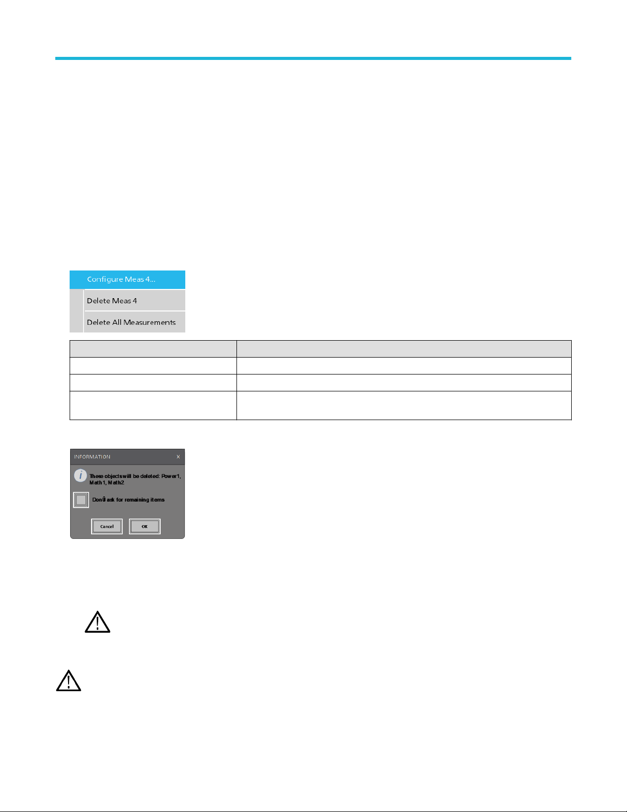
Getting acquainted with your instrument
Some searches also provide Min and Max navigation buttons that open the Zoom mode and center the waveform in the display at the
minimum or maximum value for that search event in the current acquisition.
Search badges are listed in the order created. Deleting a Search badge does not change the order or names of the remaining badges.
ou can drag Search badges to change their position in the Results
Y
menu.
There are two ways to delete Channel and Waveform badges.
• Right-click the badge and turn it off.
• Flick the badge off the right edge of the display to remove it from the Results bar. Flicking left from the right edge of the Results bar
recovers the badge. Badge recovery is only possible within 10 seconds of removal.
bar and open the badge right-click menu to access a quick-action
Deleting mass Measurements/Searches badges at Once
This badge helps you to delete/remove many number measurements or searches, which are in the Results bar.
1. Select and right click on the Measurement/Search badge in the Results bar, which displays the dialog box as shown:
Controls Description
Configure Measurement/Search Configure Measurement or Search badges
Delete Measurement/Search Deletes the selected Measurement (standard, jitter, power, DDR, etc.)/Search badge
Delete all Measurement/Search Deletes all the Measurement (standard, jitter, power, DDR, etc.)/Search badge in the
Results bar.
2. When Delete All Measurements is selected, the oscilloscope asks for the confirmation to delete all the measurements/search at a
time.
3. The dialog box provides you a checkbox that gives the choice to bypass remaining information dialogs.
• Don’t ask for remaining items: Default is unchecked. If you leave it unchecked and clear the information dialog, then the dialog
will appear again for the next measurement deletion.
• If the box is checked, it proceeds with deleting the rest of the items without bringing up the dialog box again.
Note: The dialog box appears for each set of measurements you want to delete.
Signal Clipping and Badges
Warning: Clipping is caused by excessive or dangerous voltage at the probe tip, and/or a vertical scale setting that is not
adequate to display the entire vertical range of the waveform. Excessive voltage at the probe tip can injure the operator and cause
damage to the probe and/or instrument.
5 Series B Mixed Signal Oscilloscopes MSO54B, MSO56B, MSO58B Quick Start Manual 32
Page 33
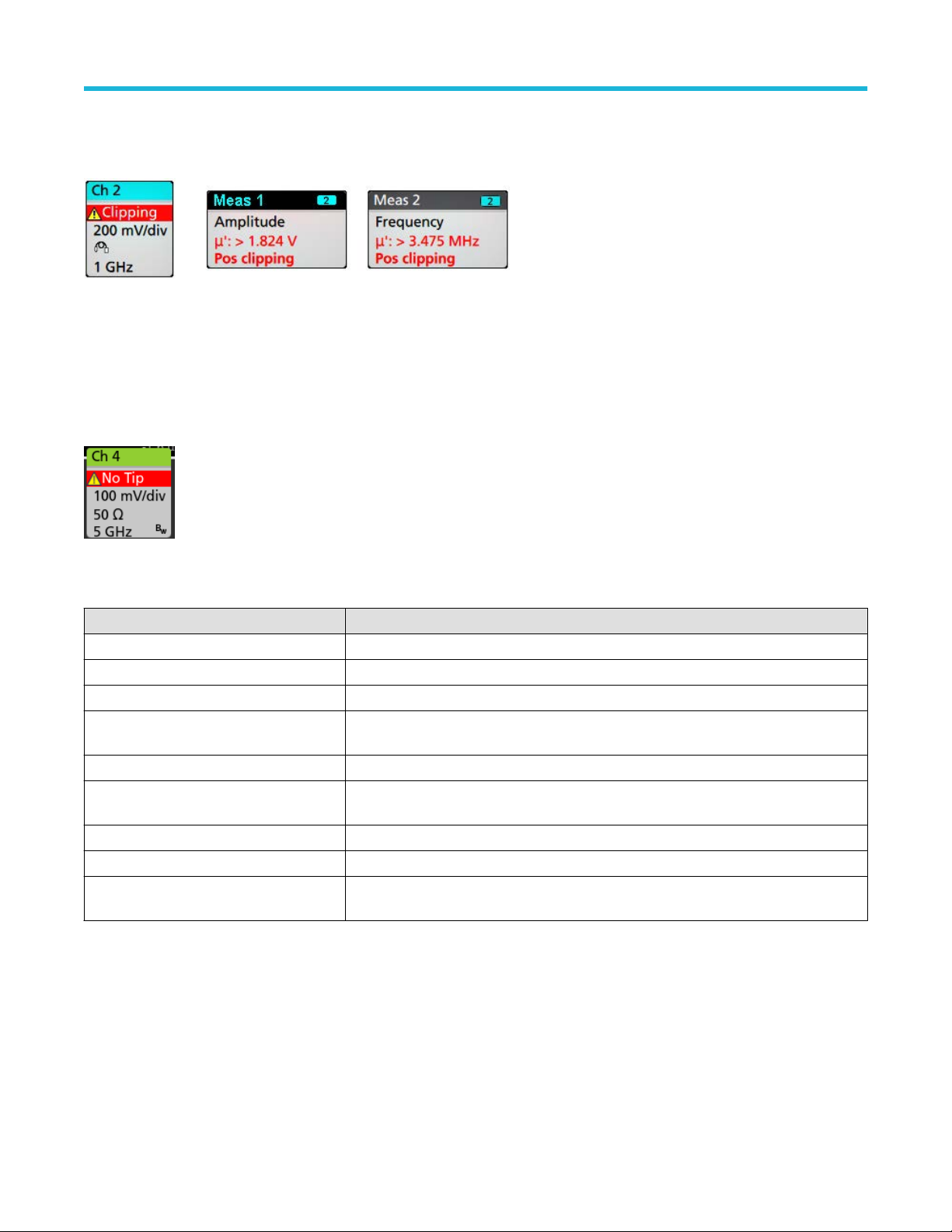
Getting acquainted with your instrument
This instrument shows a warning triangle symbol and the words Clipping in a Channel badge when a vertical clipping condition exists. Any
measurement badges associated with that channel also indicate a clipping condition by turning the measurement text red and listing the
type of clipping (positive or negative).
To close the clipping message, change the vertical scale to show the entire waveform, disconnect the probe tip from the excessive voltage
source, and check that you are probing the correct signal using the correct probe.
Clipping causes inaccurate amplitude-related measurement results. Clipping also causes inaccurate amplitude values in saved waveform
files. If a math waveform is clipped, it will not affect amplitude measurements on that math waveform.
Error Messages and Badges
This instrument shows a warning triangle symbol and an error message abbreviation in a Channel badge when an error occurs.
To remove the message from the badge, clear the error as indicated in the table.
Table 3: Probe errors
Error message Description
Prb Comm Accessory communication timed out. Please re-attach the accessory.
Prb ROM Unable to read probe ROM. Please re-attach the accessory.
Unsup Accessory is unsupported.
Prb Fault Critical accessory fault. Please re-attach the accessory. If the problem persists, contact
Tektronix service.
Over Rng The signal voltage or current is over range. Please reduce the signal amplitude.
T
emp The probe has experienced an over temperature condition. Please remove the probe from
the high temperature area.
No Tip No probe tip detected. Please install a compatible probe tip.
Tip Fault The probe tip has a fault. Please remove and replace the probe tip.
S-param Error during S-parameter transfer. Please reattach the probe. If the problem persists,
contact Tektronix Service.
History badge
The History badge is shown in the Results bar
. Navigate the history acquisitions by using the Previous/Next or Play/Pause buttons.
imestamp shows the time difference between the previous acquisition and the selected acquisition.
T
5 Series B Mixed Signal Oscilloscopes MSO54B, MSO56B, MSO58B Quick Start Manual 33
Page 34

Badge readout Function Description
Previous The previous button takes you to the previous acquisition.
Next The next button takes you to the next acquisition.
Play/Pause Acquisitions are played at the specified playback speed and begin from the
Rewind The Rewind button takes you back to the acquisitions where you pressed the Play
currently selected acquisition. The Play button changes to a Pause button when
playback is active. Acquisitions are played until playback reaches the end of the
history. At this point, playback stops, and the Play button is grayed out.
button.
Getting acquainted with your instrument
Reset The Reset button takes you back to the first acquisition in the history. When you
are at the beginning of the history the button is grayed out.
The waveforms can be viewed in the graticule for the selected acquisitions from history badge. You can navigate the total number of
acquisitions in history. Double-tap a badge to open its configuration menu.
Include Reference Acquisition in Badge is selected from the right click menu of the History badge, the badge displays the
When
following information:
The Reference acquisition readout shows the timestamp when the acquisition occurred in time in history. It also displays the delta between
the Selected acquisition and the Reference acquisition timestamps.
There are two ways to delete the History badge.
• Right-click the badge and select Disable Acquisition History
• Flick the badge off the right edge of the display to remove it from the Results bar. Flicking left from the right edge of the Results bar
recovers the badge. Badge recovery is only possible within 10 seconds of removal.
5 Series B Mixed Signal Oscilloscopes MSO54B, MSO56B, MSO58B Quick Start Manual 34
.
Page 35

System badges
Getting acquainted with your instrument
System badges (in the Settings bar) display the main Horizontal, Trigger
Double-tap a System badge to open its configuration menu.
The Horizontal badge also has Scale buttons, shown by single-tapping the badge. Use the Horizontal Scale buttons to increase or
decrease the horizontal time setting.
, and Acquisition settings. You cannot delete System badges.
Common badge actions
Action Result Example
Single tap Immediate access controls (Scale,
Navigation).
Double tap Configuration menu with access to all
settings for the badge.
Touch and hold Right-click menu with single tap
access to common actions. Typical
actions include turning of
and deleting a measurement or
search badge.
Flick Flick the badge off the bottom edge of the display to remove it from the Settings bar.
Flick the badge of
Flick from the right or bottom edge to recover a removed badge. This action is only possible within 10 seconds of
badge removal.
f a channel
f the right edge of the display to remove it from the Results bar.
Badge selection status
The appearance of a badge indicates its selection status (selected or unselected), or if a measurement needs to be deleted to close a
channel or waveform badge.
5 Series B Mixed Signal Oscilloscopes MSO54B, MSO56B, MSO58B Quick Start Manual 35
Page 36

Getting acquainted with your instrument
Badge type Selected Unselected
Turned off or in use
1
Channel or
Waveform
Measurement N/A
Configuration menus
Configuration menus let you quickly set the parameters for channels, system settings (Horizontal, Trigger
cursor readouts, Waveform and Plot views, callout text, and so on.
Double-tap an item (badge, Waveform View or Plot View, cursor readouts, callout text, and so on) to open its configuration menu. For
example, double-tap a Channel badge in the Settings Bar to open its configuration menu.
, Acquisition), measurements,
Selections or values that you enter take effect immediately. Menu contents are dynamic, and can change depending on your selections,
instrument options, or attached probes.
Related settings are grouped into 'panels'. Tap the panel name to show those settings. Changes to panel settings can change the values
and/or fields shown in that panel and other panels.
1
A dimmed Channel badge means the screen waveform is turned off (but not deleted). A dimmed W
is being used as a source by a measurement and cannot be deleted until the measurement is deleted.
aveform badge means that the waveform display is turned off, or it
5 Series B Mixed Signal Oscilloscopes MSO54B, MSO56B, MSO58B Quick Start Manual 36
Page 37

Getting acquainted with your instrument
Tap anywhere outside a configuration menu to close it.
T
o open Help content for a configuration menu, tap the question mark icon in the upper right corner of the menu.
Zoom user interface
Use the zoom tools to magnify waveforms to view signal details.
1. The Zoom Overview shows the entire waveform record. All waveforms are shown in Overlay mode in the Zoom Overview area.
Note: Using pinch and expand gestures on the Zoom Overview waveforms changes the horizontal time base settings.
2. The Zoom Box shows the area of the Zoom Overview to display in the Zoom View (see 5). Y
the area to view. You can also use the zoom Pan knob to move the Zoom Box left or right.
Note: Moving the Zoom Box, or changing its position, does not change the horizontal time base settings.
3. The Zoom icon (in the upper right corner of the W
4. The Zoom View shows the zoomed waveforms, as marked by the Zoom Box, in the Zoom Waveform Record View. Use pinch and/or
drag options in the zoom view to change the zoomed area of interest.
5 Series B Mixed Signal Oscilloscopes MSO54B, MSO56B, MSO58B Quick Start Manual 37
aveform V
iew) switches zoom mode on and off.
ou can touch and drag the box to move
Page 38

Getting acquainted with your instrument
Note: Pinch, expand, and drag gestures in the Zoom View only change zoom magnification settings and Zoom Box position.
5. Use the
Zoom Title Bar
controls to adjust the vertical and horizontal size of the zoom area. Click or tap the + or - buttons.
Using the touch screen interface for common tasks
Use standard touch screen actions, similar to those found on smart phones and tablets, to interact with most screen objects. You can also
use a mouse to interact with the UI. The equivalent mouse operation is shown for each touch operation.
The oscilloscope has a user interface tutorial. T
Table 4: Common touchscreen UI tasks with mouse equivalents
Task Touchscreen UI action Mouse action
Add a channel, math, reference,
or bus waveform to the screen.
Select a channel, math,
reference, or bus waveform to
make it active
Display scale or navigation
buttons on a badge
(waveform, measurement2,
search, horizontal).
Open a configuration menu on
any item (all badges, views,
cursor readouts, labels, and so
on).
Open a right-click menu
(badges, views).
Close a configuration menu.
Move a menu. Touch and hold the menu title bar or a blank area
Move a callout.
4
Table continued…
Tap an inactive channel button, Add New Math,
Add New Reference, or Add New Bus button.
Stacked or Overlay mode: Tap the Channel or
Waveform badge.
Stacked mode: T
or bus waveform slice or handle.
Overlay mode: Tap the channel or waveform
handle.
Tap the badge. Click the badge.
Double-tap the badge, view, or other object. Double-click the badge, view, or other object.
Touch and hold on the badge, Waveform View, Plot
view
3
ap anywhere outside the menu or dialog. Click anywhere outside the menu or dialog.
T
in the menu, then drag the menu to new position.
Touch and hold on a callout and quickly 5 start to
drag, then move to new position.
ap Help > User Interface Tutorial to quickly learn the fundamental touch operations.
Click an inactive channel button, Add New Math,
Add New Reference, or Add New Bus button.
Stacked or Overlay mode: Left-click the Channel or
Waveform badge.
ap the channel, math, reference,
Stacked mode: Left-click the channel, math,
reference, or bus waveform slice or handle.
Overlay mode: Left-click the channel or waveform
handle.
Right-click the object.
, or other screen item until a menu opens.
Click and hold the right mouse button on title or
blank area, drag to new position.
Click and hold the right mouse button on the
callout and quickly start to drag, then move to the
new position.
2
Not all measurement or search badges display navigation buttons.
3
Some dialog boxes will not close until you click an OK, Close, or other button in the dialog.
4
Callouts are screen objects and are not associated with any particular waveform channel or slice.
5
Start to move the callout as soon as selected (highlighted), otherwise the UI opens the right-click menu.
5 Series B Mixed Signal Oscilloscopes MSO54B, MSO56B, MSO58B Quick Start Manual 38
Page 39

Getting acquainted with your instrument
Task Touchscreen UI action Mouse action
T
Change horizontal or vertical
settings directly on a waveform.
ertical changes only apply
V
to the selected channel or
waveform; horizontal changes
apply to all channels and
waveforms.
ap a badge and use the Scale buttons.
Touch and hold two fingertips on the waveform
view, move them together or apart vertically or
horizontally, lift from screen; repeat.
Left-click a channel, waveform, or Horizontal
badge and click on the Scale buttons.
Increase or decrease the zoom
area (while in Zoom mode)
Quickly scroll or pan a waveform
or list.
Close or open the Results Bar
to increase the Waveform View
area.
Change the position of badges
in the Settings Bar or Results
Bar.
Touch and hold two fingertips on the waveform
view, move them together or apart vertically or
horizontally, lift from screen; repeat.
Touch and drag in the waveform or list. Click and drag in the waveform or list.
Tap on the Results Bar Handle (three vertical dots
in border) or anywhere in the border between the
Waveform View and the Results Bar.
Touch and drag the badge to a new position in the
same bar.
Click the + or - buttons on the Zoom Title bar.
Click the Draw-a-Box button, draw a box around
the waveform area of interest.
Click the Results Bar Handle (three vertical dots
in border) or anywhere in the border between the
Waveform View and the Results Bar.
Click and drag the Results Bar divider.
Click and drag the badge to a new position in the
same bar.
5 Series B Mixed Signal Oscilloscopes MSO54B, MSO56B, MSO58B Quick Start Manual 39
Page 40

Configure the instrument
Set the time zone and clock readout format
Configure the instrument
Set the time zone to your region so that saved files are marked with the correct date and time information. Y
(12 or 24 hour clock).
1. Double-tap the Date/Time badge (bottom-right of screen) to open the configuration menu.
2. To turn off showing the date and time on the screen, tap Display button to Off.
To turn on date/time display again, double-tap in the blank area where the date/time badge was displayed to open the configuration
menu, and set the Display button to On.
3. Select a time format (12 Hour or 24 Hour).
4. Tap the Time Zone field and select the time zone that applies to your location.
5. Tap anywhere outside of the menu to close it.
ou can also set the time format
Download and install the latest instrument firmware
Installing the latest firmware helps ensure that your instrument has the latest features and is taking the most accurate measurements.
Prerequisite: Save any important on-instrument files (waveforms, screen captures, setups, and so on) to a USB drive or network. The
installation process does not remove user-created files, but it is a good idea to back up important files before an update.
Determine the current version of firmware installed on the instrument (see Help > About).
Update instrument firmware from a USB drive
1. To download the instrument firmware and install onto a USB drive:
a. Open up a Web browser on a PC and go to www.tek.com/product-support
b. Enter the instrument model number in the search field and click Go.
c. Scroll down the screen and click the Software tab.
d. If the listed available firmware version (Windows or non-Windows) is newer than what is on your instrument, select and download
that file to your PC.
e. Follow the installation instructions that are on the web site or that came with the downloaded firmware to create the firmware install
file.
f. Copy the firmware install file to a USB flash drive.
2. To install firmware on embedded OS instruments :
a. Power on the instrument and wait for the instrument to fully boot up.
b. Insert the USB flash drive into any instrument USB Host port.
c. The instrument detects the update firmware and opens a dialog box. Follow the on-screen instructions to install the firmware.
Note: Do not power off the instrument or remove the USB flash drive until the instrument finishes installing the firmware. The
instrument displays a message when it is OK to power of
3. To install firmware on instruments with the Windows option:
f. Remove the USB drive before powering on the instrument.
5 Series B Mixed Signal Oscilloscopes MSO54B, MSO56B, MSO58B Quick Start Manual 40
Page 41

Configure the instrument
a. Close the T
b. Insert the USB drive into any instrument USB Host port.
c. Open the Windows desktop File Explorer and navigate to and select the install file.
d. Run the firmware update file from the USB drive, or copy the firmware update file to the desktop and run the file from there.
e. Follow any on-screen instructions to install the firmware.
f. When the firmware install is finished, remove the USB drive and restart the instrument.
4. To confirm that the firmware was updated:
a. T
ap Help > About in the Menu bar.
b. Check that the firmware version number listed on the screen is the same version that you downloaded.
ekScope
Note: Do not power off the instrument, or remove the USB flash drive if installing from the drive, until the instrument finishes
installing the firmware. The instrument displays a message when it is OK to power of
program before updating the firmware.
f.
Run Signal Path Compensation (SPC)
Run SPC when you first receive an instrument, and at regular intervals, for best measurement accuracy. You should run SPC whenever
the ambient (room) temperature has changed by more than 5 °C (9 °F), or once a week if you use vertical scale settings of 5 mV per
division or less.
Signal Path Compensation (SPC) corrects for DC level inaccuracies in the internal signal path, caused by temperature variations and/or
long-term signal path drift. Failure to run SPC on a regular basis may result in the instrument not meeting warranted performance levels at
low volts per division settings.
Prerequisite: Disconnect all probes and cables from the front-panel channel inputs and rear-panel signal connectors.
1. Power on and warm up the instrument for at least 20 minutes.
2. Tap Utility > Calibration.
3. Tap Run SPC. The SPC Status readout shows Running while SPC is running. SPC can take several minutes per channel to run, so
wait until the SPC Status message changes to Pass before reconnecting probes and using the instrument.
CAUTION: You can abort the SPC calibration by tapping Abort SPC. This may leave some channels uncompensated,
resulting in possible inaccurate measurements. If you do abort the SPC, make sure to run the SPC procedure completely
before using the instrument to take measurements.
4. Close the
5. If the SPC fails, write down any error message text. Make sure that all probes and cables are disconnected and run the SPC again. If
the SPC still fails, contact Tektronix Customer Support.
Calibration configuration dialog when SPC has completed.
Compensate the TPP Series probes
Probe compensation adjusts the high frequency response of a probe for best waveform capture and measurement accuracy. The
oscilloscope can automatically test and store compensation values for an unlimited number of probe/channel combinations.
The oscilloscope stores the compensation values for each probe/channel combination, and automatically recalls the compensation values
when you plug in the probe. Probe compensation status is shown in the Probe Setup panel of the Channel configuration menu.
• If the Probe Compensation Status field displays Pass, the probe is compensated and ready for use.
• If the Probe Compensation Status field displays Default, the attached probe has not been compensated and needs to have this probe
compensation procedure run.
• If the Probe Compensation Status field displays Fail, the attached probe has failed the probe compensation procedure. Reconnect the
probe and run probe compensation again.
• If there is no probe compensation status field shown in the panel, the oscilloscope cannot store compensation values for that probe.
See the oscilloscope Help for how to manually compensate passive probes not supported by the probe compensation function.
5 Series B Mixed Signal Oscilloscopes MSO54B, MSO56B, MSO58B Quick Start Manual 41
Page 42

Configure the instrument
Use this procedure to compensate supported TPP-family probes that show a Default status when connected to the oscilloscope.
Note: Doing a Default Setup does not delete probe compensation values. A factory calibration does delete all stored probe
compensation values.
Prerequisite: The oscilloscope must be powered on for at least 20 minutes before compensating a probe.
1. Connect a supported probe to an input channel.
2. Connect the probe tip and ground lead of the probe to the PROBE COMP terminals on the lower right of the oscilloscope (see
following image).
Connect the probe tip to the 1 kHz source, and the ground clip to the ground. For best results, remove any probe tip accessories and
hold the probe tip directly onto the 1 kHz connector.
Note: Connect only one probe at a time to the PROBE COMP terminals.
3. T
urn off all channels.
urn on the channel to which the probe is connected.
4. T
5. Push the front-panel Autoset button. The screen displays a square wave.
6. Double-tap the badge of the channel that you want to compensate.
7. Tap the Probe Setup panel.
If the Probe Compensation Status says Pass, the probe is already compensated for this channel. You can move the probe to another
channel and start again from step 1, or connect a different probe to this channel and start from step 1.
If the Probe Compensation Status says Default, continue with this procedure.
8. Tap Compensate Probe to open the Probe Compensation dialog.
9. Tap Compensate Probe to run the probe compensation.
10. The probe compensation is finished when the Probe Compensation Status displays Pass. Disconnect the probe tip and ground from
the PROBE COMP terminals.
11. Repeat these steps for each supported passive probe that you want to compensate for this channel.
12. Repeat these steps to compensate supported probes on other channels of the oscilloscope.
Note: For most accurate measurements, open the Probe Setup panel and verify the Probe Compensation Status is Pass
whenever you attach a probe to a channel.
Connect to a network (LAN)
Connecting to a network allows you to remotely access the instrument.
ork with your network administrator to obtain the required information to connect to your network (IP address, Gateway IP address,
W
Subnet Mask, DNS IP address, and so on).
5 Series B Mixed Signal Oscilloscopes MSO54B, MSO56B, MSO58B Quick Start Manual 42
Page 43

Configure the instrument
1. Connect a CA
2. Select
3. Obtain or enter the network address information:
• If your network is DHCP-enabled, and the IP address field does not already show and address, tap Auto to obtain the IP address
information from the network. DHCP mode is the default mode.
• If your network is not DHCP-enabled, or you need a permanent (non-changing) IP address for this instrument, tap Manual and
enter the IP address and other values provided by your IT or system administrator resource.
4. Tap Test Connection to verify that the network connection is working. The LAN Status icon turns green when the instrument
successfully connects to your network. If you have problems connecting to your network, contact your system administration resource
for help.
T5 cable from the instrument LAN connector to your network.
Utility > I/O on the menu bar to open the I/O configuration menu.
5 Series B Mixed Signal Oscilloscopes MSO54B, MSO56B, MSO58B Quick Start Manual 43
Page 44

Operating basics
Add a channel waveform to the display
Operating basics
Use this procedure to add a channel signal to the W
1. Connect signal(s) to the channel input(s).
2. Tap an Inactive Channel button (in the Settings bar) of a connected channel.
The selected channel is added to the Waveform View and a Channel badge is added to the Settings bar.
aveform View.
3. Continue tapping Inactive Channel buttons to add more channels (digital or analog). Channels are displayed from lowest-numbered
channel at the top, to highest-numbered channel at the bottom of the view, regardless of the order they were added (in stacked mode).
4. Double-tap a channel badge to open that channel's configuration menu to check or change settings. See
waveform settings on page 45.
Configure channel or
5 Series B Mixed Signal Oscilloscopes MSO54B, MSO56B, MSO58B Quick Start Manual 44
Page 45

Operating basics
Configure channel or waveform settings
Use the channel and waveform configuration menus to set parameters such as vertical scale and offset, coupling, bandwidth, probe
settings, deskew values, external attenuation values, and other settings.
Before you begin
Prerequisite: There is a channel or waveform badge in the Settings bar.
Procedure
1. Double-tap a Channel or
For example, in a Channel menu, use the Vertical Settings panel to set basic probe parameters such as vertical scale and position,
offset, coupling, termination, and bandwidth limit.
Available settings depend on the probe.
Waveform badge to open a configuration menu for that item.
2. Tap the Probe Setup panel to confirm probe settings and run configuration or compensation on supported probes.
5 Series B Mixed Signal Oscilloscopes MSO54B, MSO56B, MSO58B Quick Start Manual 45
Page 46

3. Tap the Other panel to set probe deskew, external attenuation, and alternate units parameters.
4. Tap the Help icon on the menu title to open the help topic for more information.
ap outside the menu to close the menu.
5. T
Operating basics
Autoset to quickly display a waveform
The Autoset function analyzes the signal characteristics and changes the instrument Horizontal, Vertical, and Trigger settings to
automatically display a triggered waveform. You can then make further changes to trigger and horizontal settings to view the waveform
point of interest.
1. Connect the probe with the signal of interest to an available channel. The signal can be analog or digital.
2. Double-tap the Trigger badge and set the trigger source to that of the signal of interest.
3. Connect any other associated signal(s) to available channel input(s).
4. Add the channel waveforms to the Waveform view. See Add a channel waveform to the display on page 44.
5. Tap File > Autoset or push the front-panel Autoset button. When using the Stacked Display mode, the instrument analyzes the signal
characteristics of the trigger source channel (analog or digital) and adjusts the horizontal, vertical, and trigger settings accordingly
to display a triggered waveform for that channel. The Vertical scale is adjusted in each waveform slice of all active waveforms to
maximize ADC utilization.
5 Series B Mixed Signal Oscilloscopes MSO54B, MSO56B, MSO58B Quick Start Manual 46
Page 47

Operating basics
When using the Overlay Display mode, the instrument adjusts the horizontal and trigger settings of the trigger source channel to
display a triggered waveform for that channel. V
are controlled by the Autoset in Overlay Display Mode Optimizes selection in the Autoset
the selection is Visibility, Autoset vertically scales and positions all active channel waveforms such that they are uniformly spaced on
screen. If the selection is Resolution, Autoset vertically scales and positions all active channel waveforms such that they each use as
much of the ADC's range as possible.
Note: You can set which parameters the instrument can adjust when running an Autoset. Access the Autoset panel in Utility >
User Preferences > Autoset. See
ertical scale and position adjustments for all active channels in Overlay Display mode
panel of the User Preferences menu. If
User Preferences (Utility menu).
Autoset guidelines
• Autoset displays three or four cycles (depending on the detected signal) with the trigger level near the midlevel of the signal.
•
The trigger is set to type Edge, rising slope, DC coupling.
• If no channels are displayed before pushing Autoset, the oscilloscope adds Ch 1 to the Waveform view whether it has a signal or not.
• Autoset ignores math, reference, and bus waveforms.
• A channel or waveform with a frequency less than 40 Hz is classified as no signal.
How to trigger on a signal
Use this procedure to open the Trigger menu to select and configure the trigger event type and conditions.
1. Double-tap the Trigger badge on the Settings bar to open the Trigger configuration menu.
2. Select a trigger from the Trigger Type list. The trigger type sets what fields are available in the menu and also updates the illustration
to show a graphic of the trigger type.
To trigger on a bus, you must first add the bus to the Waveform view. See Add a math, reference, or bus waveform on page
Note: Triggering on buses other than Parallel requires purchasing and installing serial trigger and analysis options.
49
3. Select the other fields and panels to refine the trigger conditions. The menu fields and trigger graphic update as you make changes to
the trigger settings. Displayed fields depend on the selected trigger type. Selection changes take effect immediately
5 Series B Mixed Signal Oscilloscopes MSO54B, MSO56B, MSO58B Quick Start Manual 47
.
Page 48

4. Tap the Help icon on the menu title for more information on these settings.
5. T
ap outside the menu to close the menu.
Set the acquisition mode
Use this procedure to set the method the instrument uses to acquire and display the signal.
Operating basics
1. Double-tap the Acquisition badge on the Settings bar to open the Acquisition configuration menu.
2. Select the acquisition method from the Acquisition Mode list. Set any other parameters associated with the selected acquisition type.
3. Tap the Help icon on the menu title for more information on these settings.
4. T
ap outside the menu to close the menu.
Set Horizontal parameters
Use this procedure to set the horizontal time base parameters such as mode, minimum sample rate, horizontal scale, delay, and trigger
delay time (relative to the center of the waveform record.
1. Double-tap the Horizontal badge on the Settings bar to open the Horizontal configuration menu.
2. Use the menu selections to set horizontal parameters.
3. Tap the Help icon on the menu title for more information on these settings.
5 Series B Mixed Signal Oscilloscopes MSO54B, MSO56B, MSO58B Quick Start Manual 48
Page 49

Operating basics
Add a math, reference, or bus waveform
Math waveforms let you create new waveforms based on operations between two or more waveforms or by applying equations to
waveform data. A reference waveform is a static waveform record displayed for comparison. Bus waveforms let you view and analyze
serial or parallel data.
There is no set limit to the number of Math, Reference, or Bus waveforms you can add to the Waveform V
memory constraints.
1. Tap the Add New Math, Add New Ref, or Add New Bus button in the Settings bar.
2. The instrument adds the waveform to the Waveform view
menu. This example shows adding a Math waveform.
3. Use the configuration menus to refine the waveform parameters. Displayed fields depend on the waveform and selections made in the
menu. Selection changes take effect immediately
This example shows adding a Math waveform, using the Math Source fields to select Ch 1 and Ch 2 as the waveform sources, set the
math type to Basic math operation, and subtracting channel 2 from channel 1.
, adds a Waveform badge to the Settings bar, and opens a configuration
.
iew, other than system physical
4. When adding a Reference waveform, the instrument displays a Recall configuration menu. Navigate to and select the reference
waveform file (*.wfm) to recall, then tap the Recall button. The instrument displays the Reference waveform.
5. Double-tap a math, reference, or bus badge to check or change the waveform settings. See
settings on page 45.
6. Tap the Help icon on a configuration menu title for more information on math, reference, and bus waveform settings.
7. Tap outside the menu to close the menu.
5 Series B Mixed Signal Oscilloscopes MSO54B, MSO56B, MSO58B Quick Start Manual 49
Configure channel or waveform
Page 50

Add a measurement
Use this procedure to select and add measurements.
1. Acquire the channel(s) and/or waveform(s) on which you want to take measurements.
Operating basics
Note: Waveforms do not need to be displayed to be used for measurements, as long as the channel or waveform badge is
Settings bar and is acquiring the signal to measure.
on the
2. Tap the button to open the Add Measurements
display area to automatically set the source.
Note: If the menu shows tabs other than Standard, then optional measurement types have been installed on the
instrument. Select a tab to show the measurements for that option.
3. Tap the Source field and select the measurement source. The list shows all available sources that are valid for the measurement.
configuration menu or drag the Measure button onto a waveform in the waveform
5 Series B Mixed Signal Oscilloscopes MSO54B, MSO56B, MSO58B Quick Start Manual 50
Page 51

Operating basics
4. Select a measurement category panel, such as Amplitude Measurements or Timing Measurements, to display measurements for
those categories.
5. Some optional measurement packages are available in this menu as well like PWR, DJA, DBDDR3, DPM, IMDA.
6. Select a measurement and tap Add to add the measurement to the Results bar. You can also double-tap a measurement to add it to
the Results bar.
7. Select and add other measurements for the current source. Tap the measurement category panels to display and select other
measurements to add.
o add measurements for other sources, select a different source, select a measurement, and add the measurement.
8. T
9. Tap outside the Add Measurements
10. To further adjust a measurement's settings, double-tap a measurement badge to open a configuration menu for that measurement.
See Configure a measurement on page 52.
5 Series B Mixed Signal Oscilloscopes MSO54B, MSO56B, MSO58B Quick Start Manual 51
menu to close the menu.
Page 52

Operating basics
ap the Help icon on the menu title for more information on settings.
11. T
Configure a measurement
Use this procedure to add statistical readouts to the measurement badge, display plots for the measurement, and refine measurement
parameters (configuration, global versus local scope of settings, gating, filtering, and so on).
1. Double-tap a measurement badge to open its Measurement
2. Tap Show Statistics in Badge to add statistical readouts to the measurement badge.
3. Tap available panel titles to make changes for those categories.
configuration menu.
4. Use the available fields to refine the measurement conditions. Displayed fields depend on the measurement. Selection changes take
effect immediately
5. Tap the Help button on the menu title for more information on this menu's settings.
6. Tap outside the menu to close the menu.
5 Series B Mixed Signal Oscilloscopes MSO54B, MSO56B, MSO58B Quick Start Manual 52
. Selection changes can also change fields in other panels.
Page 53
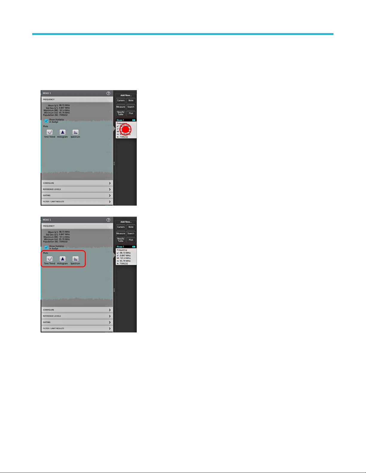
Operating basics
Add a plot of a measurement
Measurement plots let you graph the distribution of waveform data point occurrences (histogram), plot the frequency components
(spectrum) of a waveform, show the time trend of a measurement, display an eye diagram,
depend on the measurement.
1. Double-tap a Measurement badge to open the Meas configuration menu.
and other supported plots. Available plots
2. Tap a Plots button to add that plot for the measurement to the screen.
The following shows adding a Histogram plot.
5 Series B Mixed Signal Oscilloscopes MSO54B, MSO56B, MSO58B Quick Start Manual 53
Page 54

Operating basics
You can add more than one plot to measurements (to different measurements or the same measurement). For example, you can add
two histogram plots for the same measurement, set one to display the X-Axis with a Logarithmic scale, and the other plot to display the
X-Axis with a Linear scale.
3. You can move plot windows by dragging the Plot view title bar to a new position. The blue background area moves to show where the
plot will be located when you remove your finger from the title bar. Y
view border. You should use a mouse to do these operations, as it is easier to select and drag plots with a mouse.
ou can also resize plot windows by selecting and dragging the Plot
4. Double-tap within a Plot view to open a configuration menu to set display characteristics. Tap the Help icon on the configuration menu
title for more information on that menu's settings. T
ap outside the menu to close the menu.
Add a Search
Use this procedure to set search criteria and mark a waveform where those events occur.
You can search on analog signals, math waveforms, and reference waveforms. You can add searches to different waveforms and multiple
searches to the same waveform.
Prerequisite: Display the channel or waveform signal on which to search. The waveform must be displayed to create a search for it.
1. Display the channel or waveform signal on which to search. The waveform must be displayed to create a search for it.
2. Tap the button to open the Search configuration menu.
5 Series B Mixed Signal Oscilloscopes MSO54B, MSO56B, MSO58B Quick Start Manual 54
Page 55

Operating basics
3. Use the configuration menu fields to set the search criteria in the same way that you would set for a trigger condition (select the
Search Type
4. The searched waveform is marked with one or more triangles as soon as the search criteria becomes true. Each search uses a
different color for its markers. The example image shows search criteria set to find positive pulse widths that are less than 70 ns wide.
, Source, and conditions on which to search).
Note: You cannot search for sequential events (there is no Sequence search type).
5. T
o stop showing marks on a waveform, double-tap the Search
6. To move the waveform to center marks on the display, push the Run/Stop front panel button to stop acquisition, single-tap a Search
badge, and tap the < or > Navigation button.
Note: Navigation buttons are only functional when the oscilloscope acquisition mode is set to Stop.
This opens the Zoom mode and moves the waveform to the previous or next event mark on the waveform.
7. If available for a search, tap the Min or Max button to center the waveform in the display at the minimum or maximum value of the
search events in the waveform record.
8. To return the instrument to normal acquisition mode, tap the Zoom
Zoom mode, and push the Run/Stop front-panel button to set it to Run mode.
badge and tap Display to Off.
icon in the upper right corner of the Waveform View to turn off
5 Series B Mixed Signal Oscilloscopes MSO54B, MSO56B, MSO58B Quick Start Manual 55
Page 56

Delete a Measurement or Search badge
Use this procedure to remove a Measurement or Search badge from the Results bar.
ouch and hold the Measurement or Search badge that you want to delete. The instrument opens a right-click menu.
1. T
2. Select Delete Meas to delete that badge from the Results bar.
Note: You can undo a measurement delete.
Operating basics
3. The second way to delete a Measurement or Search badge is by flicking it off the right edge of the display
right edge of the display recovers the badge.
Note: Badge recovery is only possible within 10 seconds of removal.
. Flicking to the left from the
Change waveform view settings
Use this procedure to change the waveform display mode (Stacked or Overlay), waveform trace interpolation algorithm, waveform
persistence, style and intensity, and graticule style and intensity.
1. Double-tap on an open graticule area to open the Waveform View configuration menu.
2. Tap the buttons in the Display Mode to toggle between Overlay and Stacked modes.
3. Use the other controls to set the waveform interpolation algorithm, waveform point persistence, style, and intensity, and graticule style
and intensity
4. Tap the Help icon on the menu title to open the Waveform View menu help topic for more information on the waveform view
parameters.
5. Tap outside the menu to close the menu.
5 Series B Mixed Signal Oscilloscopes MSO54B, MSO56B, MSO58B Quick Start Manual 56
.
Page 57

Operating basics
Display and configure cursors
Cursors are on-screen lines that you can move to take measurements on specific parts of a waveform or plot, or between two different
waveforms. Cursor readouts show both current position values and the difference (delta) between cursors. Polar cursor readouts are
available through the cursor configuration menu for XY and XYZ plots.
ap the waveform slice (in Stacked mode), or the channel or waveform badge (in Overlay mode) to which you want to add cursors.
1. T
2. Tap the Add New...Cursors button, or push the front-panel Cursors button. The cursors are added to the display.
3. Use Multipurpose Knobs A and B to move the cursors, or touch and drag a cursor. Cursors show readouts that show position and
difference measurements between the cursors.
4. To move the cursors to a different channel or waveform, just tap in that waveform graticule.
5 Series B Mixed Signal Oscilloscopes MSO54B, MSO56B, MSO58B Quick Start Manual 57
Page 58

o further configure cursors, double-tap on either cursor line or the cursor readouts to open the Cursors configuration menu. For
5. T
example, tap the Cursor type to select the cursors to display
configuration menu.
The cursor configuration menu in the waveform view.
The cursor configuration menu in an XY plot.
, such as Waveform, V Bars, H Bars, and V&H Bars. See Cursor
Operating basics
6. To split the cursors between two waveforms, tap the Source
are moved to the specified waveforms.
field and select Split and select the source for each cursor. The cursors
5 Series B Mixed Signal Oscilloscopes MSO54B, MSO56B, MSO58B Quick Start Manual 58
Page 59

Operating basics
7. Tap the Help icon on the menu title for more information on the menu settings.
o stop showing cursors, push the front panel Cursor button, press and hold to open the right-click menu and turn cursors off, or open
8. T
the Cursors configuration menu and set Display to Off.
Remote access from a Web browser
You can remotely access your network-connected standard instrument (not running Windows) from a Web browser to display the
instrument user interface on a PC.
This procedure describes how to remotely access the UI controls and screen for standard (non Windows 10) instruments. To remotely
access the UI controls and screen for Windows 10 instruments, see the Remote access to a Windows 10 instrument topic in the Help.
Prerequisites:
• The instrument must be connected to, and accessible from, the network to which the PC is connected. See Connect to a network
(LAN) on page 42
• The IP address of the instrument that you want to access. To determine the instrument's IP address, select Utility > IO in the
instrument menu bar and view the network settings in the LAN panel.
• You are accessing a standard (instrument that does not have the Windows OS option installed).
Use below procedure to remotely access the UI controls and screen for standard (non Windows 10) instruments using e*Scope
functionality.
1. Open a Web browser on a PC connected to the same network as the instrument.
2. Enter just the instrument IP address on the URL line of the browser and press Enter. For example: 135.62.88.157. The browser
searches for and opens the Web page for the instrument.
3. Select Instrument Control (e*Scope®). The browser displays the instrument screen.
4. Use a mouse to select and interact with the instrument controls shown in the Web browser. If your remote PC or laptop has a touch
screen monitor, you can use the remote touchscreen monitor to access the instrument controls.
When you access the instrument from an e*Scope browser, you cannot directly paste text (such as path, IP address information, and so
on) from the PC to an instrument menu field. You must use an intermediate clipboard function that is available in the e*Scope application.
Use the following steps to copy text from an e*Scope-connected PC to the instrument:
1. Open a connection to the instrument using e*Scope.
5 Series B Mixed Signal Oscilloscopes MSO54B, MSO56B, MSO58B Quick Start Manual 59
Page 60

Operating basics
2. Select and copy the text on your PC.
3. In e*Scope, press Ctrl-Alt-Shift to open the Clipboard menu.
4. Paste the text into the Clipboard field.
5. Press Ctrl-Alt-Shift to close the browser Clipboard menu.
6. Use e*Scope to open the instrument menu to which to paste content, and position the cursor in the field where you want to paste the
text.
7. Press Ctrl-V (on real keyboard or from virtual keyboard) to paste the text from the e*Scope browser clipboard to the menu field.
8. Repeat steps 4.b on page 25 through 4.g on page 25 to copy and paste other text from the PC to the instrument
Connect the oscilloscope to a PC using a USB cable
Use a USB cable to connect the oscilloscope directly to a PC for remote instrument control.
1. On the oscilloscope, select Utility > I/O from the menu bar
2. T
ap USB Device Port Settings.
3. Confirm that the USB Device Port control is On (default setting).
4. Connect a USB cable from the PC to the USB Device port on the rear of the instrument.
5. If using the USB connection to remotely control the oscilloscope using GPIB commands, set the GPIB Talk/Listen Address for your
configuration (0 - 30).
.
5 Series B Mixed Signal Oscilloscopes MSO54B, MSO56B, MSO58B Quick Start Manual 60
Page 61

Maintanence
Maintenance
Inspection and cleaning
Inspection and Cleaning describes how to inspect for dirt and damage. It also describes how to clean the exterior and interior of the
instrument. Inspection and cleaning are done as preventive maintenance. Preventive maintenance, when done regularly
instrument malfunction and enhance its reliability.
Preventive maintenance consists of visually inspecting and cleaning the instrument and using general care when operating it.
How often to perform maintenance depends on the severity of the environment in which the instrument is used. A proper time to perform
preventive maintenance is just before instrument adjustment.
Exterior cleaning (other than display)
Clean the exterior surfaces of the chassis with a dry lint-free cloth or a soft-bristle brush. If any dirt remains, use a cloth or swab dipped in
a 75% isopropyl alcohol solution. Use a swab to clean narrow spaces around controls and connectors. Do not use abrasive compounds on
any part of the chassis that may damage the chassis.
Clean the On/Standby switch using a cleaning towel dampened with deionized water. Do not spray or wet the switch itself.
, may prevent
CAUTION: A
deionized water when cleaning the front-panel buttons. Use a 75% isopropyl alcohol solution as a cleaner for cabinet parts. Before
using any other type of cleaner
Inspection - Exterior. Inspect the outside of the instrument for damage, wear, and missing parts. Immediately repair defects that could
cause personal injury or lead to further damage to the instrument.
void the use of chemical cleaning agents which might damage the plastics used in this instrument. Use only
, consult your T
ektronix Service Center or representative.
Table 5: External inspection checklist
Item Inspect for Repair action
Cabinet, front panel, and cover Cracks, scratches, deformations, damaged
hardware
Front-panel knobs Missing, damaged, or loose knobs Repair or replace missing or defective knobs
Connectors Broken shells, cracked insulation, and
deformed contacts. Dirt in connectors
Carrying handle and cabinet feet Correct operation Repair or replace defective module
Accessories Missing items or parts of items, bent pins,
broken or frayed cables, and damaged
connectors
Repair or replace defective module
Repair or replace defective modules. Clear
or brush out dirt
Repair or replace damaged or missing items,
frayed cables, and defective modules
Flat panel display cleaning
Clean the flat panel display surface by gently rubbing the display with a clean-room wipe (such as Wypall Medium Duty Wipes, #05701,
available from Kimberly-Clark Corporation), or an abrasive-free cleaning cloth.
If the display is very dirty, moisten the wipeor cloth with distilled water
gently rub the display surface. Use only enough liquid to dampen the cloth or wipe. Avoid using excess force or you may damage the
display surface.
CAUTION: Improper cleaning agents or methods can damage the flat panel display
•
Do not use abrasive cleaners or surface cleaners to clean the display.
Do not spray liquids directly on the display surface.
•
5 Series B Mixed Signal Oscilloscopes MSO54B, MSO56B, MSO58B Quick Start Manual 61
, a 75% isopropyl alcohol solution, or standard glass cleaner, and
.
Page 62

Maintanence
• Do not scrub the display with excessive force.
CAUTION: To prevent getting moisture inside the instrument during external cleaning, do not spray any cleaning solutions directly
onto the screen or instrument.
Service the instrument
For more information on troubleshooting, maintenance, and replacing parts on your instrument refer to the instrument service manual or
contact a Tektronix Service Center
.
Returning the instrument for service
When repacking the instrument for shipment, use the original packaging. If the packaging is unavailable or unfit for use, contact your local
Tektronix representative to obtain new packaging.
Seal the shipping carton with an industrial stapler or strapping tape.
Before returning the instrument for service, contact the Service Center to get an RMA (return material authorization) number, and any
return or shipping information you may need.
If the instrument is being shipped to a Tektronix Service Center, enclose the following information:
• The RMA number.
• The owner's address.
• Name and phone number of a contact person.
• Type and serial number of the instrument.
• Reason for returning.
• A complete description of the required service.
Mark the address of the Tektronix Service Center and the return address on the shipping carton in two prominent locations.
5 Series B Mixed Signal Oscilloscopes MSO54B, MSO56B, MSO58B Quick Start Manual 62
Page 63

Index
A
A knob 19
Acquisition controls
acquisition menu, open 48
add
a channel to the display 44
a measurement badge
a measurement plot 53
a search badge 54
signal to the screen 44
waveform to the screen 44
Add New
Bus waveform button 26
Math waveform button 26
Ref waveform button 26
AFG option 26
AFG Out (rear panel) 23
automatic probe compensation (TPP series) 41
Autoset 46
Autoset button 19
AUX Out (rear panel) 23
19
50
B
connecting probes 17
correct handle rotate 14
Cursors button 19
Cursors button (touchscreen) 24
cursors menu 57
D
Default Setup button 19
delete a measurement badge 56
display a channel 44
display cursors 57
documentation 4
Draw-a-Box button (Zoom) 37
DVM option 26
dynamic range limit marker 26
E
e*Scope 59
Environment requirements 15
Ethernet port (rear panel) 23
Ethernet, connect to 42
expansion point, waveform 26
B knob 19
badge types 28
badges 28
Bus button 19
bus waveforms 49
C
cable lock 23
Callout button 24
change display settings 56
change measurement settings 52
channel badge 28
Channel buttons (front panel) 19
channel menu 45
channel settings 45
channel vertical parameters menu 45
Clear button 19
clipping message 28
clock format (12/24 hr), how to set 40
common touchscreen UI tasks 38
compensate TPP series probes 41
configuration menus 36
configure a measurement 52
connect lock cable 16
connect to a network 42
F
Fast Acq button 19
Feature list 13
firmware, how to update 40
FlexChannel connectors (front panel) 19
Force button 19
front panel
Acquisition 19
Autoset button 19
19
Aux In
Aux Trig 19
Bus button (front panel) 19
Channel buttons (front panel) 19
Clear button 19
Cursors button 19
Default Setup 19
description 19
Fast Acq button 19
FlexChannel connectors 19
Force button 19
High Res button 19
Horizontal 19
Level knob 19
Math button (front panel) 19
Miscellaneous 19
|
Page 64

front panel (continued)
Mode button 19
multipurpose knobs
Navigate buttons (front panel) 19
Position knob 19
Position knob (horizontal) 19
probe compensation connectors 19
Ref button (front panel) 19
Run/Stop button 19
Scale knob 19
Scale knob (horizontal) 19
Single/Seq button 19
Slope button 19
Touch Off button 19
Trigger 19
USB ports 19
Vertical 19
Zoom button (front panel) 19
Zoom/Pan knobs (horizontal) 19
19
G
GPIB talk/listen address 60
graticule intensity 56
graticule style 56
H
how to (continued)
open acquisition menu 48
open horizontal menu
quickly display waveform (Autoset) 46
remote access the instrument (from Web) 59
run signal path compensation (SPC) 41
search on an event 54
set acquisition parameters 48
set channel vertical parameters 45
set clock format (12/24 hr) 40
set GPIB talk/listen address 60
set horizontal parameters 48
set probe deskew 45
set probe parameters 45
set time zone 40
set trigger parameters 47
use Autoset 46
use mouse with the UI 38
How to
change display mode (stacked, Overlay) 56
48
I
inactive channel buttons
input signal level requirements 15
intensity, graticule 56
intensity, waveform 56
26
handle rotate 14
handles, analog and digital 26
High Res button 19
Horizontal controls 19
horizontal menu, open 48
how to
add a measurement 50
add a measurement plot
Add bus waveform 49
Add math waveform 49
Add reference waveform 49
add waveform to screen 44
change display settings 56
change graticule intensity 56
change graticule style 56
change measurement settings 52
change persistence 56
change waveform intensity 56
change waveform interpolation 56
check power-on self tests results 17
compensate TPP series probes 41
connect probes 17
connect to network 42
connect to PC using USB cable 60
delete a measurement 56
display cursors 57
download, install firmware 40
53
K
knob A 19
knob B 19
L
LAN port (rear panel) 23
LAN, connect to 42
Level knob 19
Level knob LED 19
lock to bench or rack 16
M
manuals 4
marking waveform events (search) 54
Math button 19
math waveforms 49
Measure button 24
measurement
plots 53
measurement badge 28
measurement badge, delete
Menu bar 24
menu panels 36
menus 36
56
|
Page 65

Miscellaneous controls 19
Mode button (front panel)
More button 24
mouse touchscreen UI equivalents 38
move cursors 57
multipurpose knobs 19
19
N
Navigate buttons (horizontal) 19
navigation buttons, badges 28
network, connect to 42
O
open acquisition menu 48
open horizontal menu 48
operating
altitude range 15
humidity range 15
temperature range 15
operating power requirements 15
overlay mode (waveforms) 56
P
Pan 37
panels, menu 36
persistence, waveform 56
pinching and handle rotate 14
plot a measurement 53
Plot button 24
Position knob 19
Position knob (horizontal) 19
power cord connector (rear panel) 23
power cord wrap 16
power requirements 15
power standby mode 16
power-on test results 17
powering on or off 16
probe compensation connectors 19
probe deskew, set 45
probe inputs 19
probe parameters, set 45
probes, connecting 17
proper handle rotate 14
R
rack mount kit information 18
rear panel
AFG Out 23
AUX Out 23
cable lock 23
Ethernet port (RJ-45) 23
rear panel (continued)
LAN port (RJ-45) 23
power cord 23
security cable lock
USB Device port 23
USB Host ports 23
video output 23
rear panel connections 23
record view, waveform 26
Ref button 19
Ref In 23
Ref In (rear panel) 23
reference waveforms 49
remote access (e*Scope) 59
remote access (Web-based) 59
remove AC power from instrument 16
requirements
altitude 15
environment 15
humidity 15
power 15
signal inputs 15
temperature 15
Results bar 24
Results Table button 24
run signal path compensation 41
Run/Stop button 19
23
S
Save button 19
scale buttons, badge 28
Scale knob 19
Scale knob (horizontal) 19
search badge 28
Search button 24
searching for events 54
security cable lock 23
set
clock format (12/24 hr) 40
GPIB talk/listen address
probe deskew 45
probe parameters 45
time zone 40
Settings bar 24
show a measurement 50
signal input levels 15
Single/Seq button 19
Slope button (front panel) 19
SPC (signal path compensation) 41
stacked mode (waveforms) 56
standard accessories 14
60
|
Page 66

T
TekVPI input connectors
time zone, how to set 40
Touch Off button 19
touchscreen UI tasks 38
trigger
level indicators 26
position indicator
Trigger controls 19
trigger menu 47
trigger the oscilloscope 47
turn instrument on or off 16
19
26
U
USB cable, connect to PC 60
USB Device port (rear panel) 23
USB Host ports (rear panel) 23
USB ports (front panel) 19
use cursors 57
user documentation 4
using mouse with the touchscreen 38
V
Vertical controls 19
video output (rear panel) 23
W
waveform
expansion point 26
intensity 56
persistence 56
record view 26
waveform badge 28
Waveform V
iew 24
Z
Zoom box 37
Zoom button (front panel) 19
zoom icon 26
Zoom overview 37
Zoom title bar 37
Zoom/Pan knobs (horizontal) 19
|
Page 67

5 シリーズ B ミックスド・シグナル・オシロスコープ
MSO54B 型、MSO56B 型、MSO58B 型
クイック・スタート・マニュアル
警告:保守点検に関する説明は、資格のあるサービス担当者のみを対象としています。危害がおよぶ恐れがありますので、資
格がない限り保守点検を行わないでください。保守点検を実行する前に、すべての安全性に関するサマリをご覧ください。
ファームウェア V1.36 以降をサポート
Register now
Register your product
Product registration link
*P077172300*
077-1723-00
Page 68

Copyright © Tektronix.All rights reserved.使用許諾ソフトウェア製品は、T
ので、米国著作権法および国際条約の規定によって保護されています。テクトロニクス製品は、登録済および出
願中の米国その他の国の特許等により保護されています。本書の内容は、既に発行されている他の資料の内容に
代わるものです。また、本製品の仕様および価格は、予告なく変更させていただく場合がございますので、予め
ご了承ください。
TEKTRONIX および TEK は Tektronix, Inc.の登録商標です。
ektronix またはその子会社や供給者が所有するも
当社へのお問合せ
Tektronix, Inc.
14150 SW Karl Braun Drive
P.O. Box 500
Beaverton, OR 97077
USA
製品情報、代理店、サービス、およびテクニカル・サポート:
• 北米:1-800-833-9200 までお電話ください。
• 世界の他の地域では、www.tek.com にアクセスし、お近くの代理店をお探しください。
Page 69

保証期間
保証期間
当社は本製品について、当社の認定代理店による出荷の日から 1 年間、その素材および製造工程に欠陥がないこ
とを保証します。本保証期間中、かかる製品に材料または製造上の欠陥があることが判明した場合、当社は、当
社の判断にて、部品および作業の費用を請求せずに当該欠陥製品を修理するか、または当該欠陥製品と交換に代
替品を提供します。当社が保証遂行のために使用する部品、
新品同様の性能を持つ再生品の場合もあります。交換後、当社が引き取った部品、モジュール、および製品はす
べて当社の所有物となります。
お客様が本保証に基づくサービスを受けるには、適用保証期間が満了する前に、当該欠陥について当社に通知し、
サービス実施に関する適切な手配を行う必要があります。お客様には、当該欠陥製品を梱包していただき、送料
元払いにて当社指定のサービス受付センターに送付していただきます。製品をお客様に返送する際、返送先が当
社サービス受付センターの所在国と同一国内にある場合には、当社がその返送費用を負担するものとします。上
記以外の場所に返送される製品については、すべての発送費用、関税、税、およびその他の費用を支払う責任は
お客様が負うものとします。
製品の不適切な使用または整備点検の不足によって生じた欠陥、障害、または損傷は、本保証の対象外です。当
社は、次の事項については、本保証に基づくサービスを提供する義務を負わないものとします。a)当社担当者以
外の者による本製品の設置、修理または整備の実施から生じた損傷に対する修理。b)不適切な使用または互換性
のない機器への接続から生じた損傷に対する修理。c)当社製以外のサプライ用品の使用により生じた損傷または
動作不良に対する修理。d)本製品が改造または他の製品と統合された場合において、かかる改造または統合の影
響により当該本製品の整備の時間または難易度が増加した場合の当該本製品に対する整備。
モジュール、および代替品は、新品の場合もあれば、
本保証は、明示であるか黙示であるかを問わず他のあらゆる保証の代わりに、本製品に関して当社がお客様に対
して提供するものです。当社およびその販売店は、非侵害、満足できる品質、商品性、特定目的への適合性とい
った黙示的保証を含むがこれに限定されない、いかなる黙示的保証も放棄します。不具合のある製品を修理また
は交換するという当社の責任行為は、本保証の義務違反に対してお客様に提供される唯一の救済手段です。当社
および当社代理店は、間接的、限定的、懲罰的、偶発的、または派生的な損害については、かかる損害の可能性
を事前に通知されていたか否かにかかわらず、一切責任を負わないものとします。
[W2 – 15AUG04]
5 シリーズ B ミックスド・シグナル・オシロスコープ MSO54B 型、MSO56B 型、MSO58B 型 クイック・スタート・
マニュアル 3
Page 70
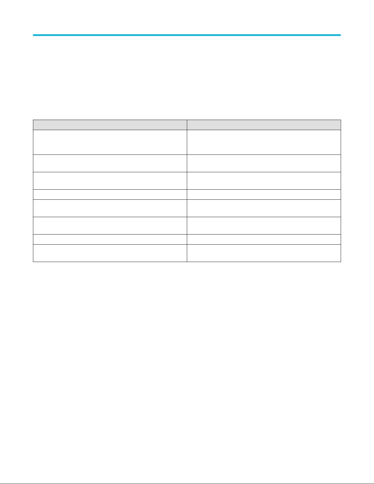
マニュアル
マニュアル
本機をインストールして使用する前に、以下のユーザ・マニュアルの内容を確認してください。これらの文書に
は、操作に関する重要な情報が記載されています。
製品マニュアル
次の表は、
マニュアルは、www.tek.com からダウンロードできます。その他、デモンストレーション・ガイド、テクニカル・
ブリーフ、アプリケーション・ノートなどの情報も、www.tek.com でご覧いただけます。
マニュアル 内容
ヘルプ 製品の操作に関する詳細な情報。製品の UI にあるヘル
クイック・スタート・ユーザ・マニュアル 製品のハードウェアとソフトウェアの紹介、インストー
仕様および性能検査のテクニカル・リファレンス 機器の性能をテストするための、仕様および性能検査の
プログラマ・マニュアル 本機器をリモート制御するためのコマンド。
機密およびセキュリティに関する説明 機器のメモリの位置に関する情報。機器の機密保護お
サービス・マニュアル 交換部品リスト、動作原理、機器を整備するための交換
アップグレード手順 製品アップグレードのインストールに関する情報。
ラックマウント・キット取扱説明書 特定のラックマウントを使用して、機器を組み立て、マ
ご使用の製品で入手可能な主な製品別マニュアルの一覧です。これらのマニュアルやその他のユーザ・
・ボタンから利用できるほか、www.tek.com から PDF を
プ
ダウンロードすることもできます。
ル方法、電源の入れ方、基本的な操作方法など。
手順。
よびセキュリティ確保の手順。
手順。
ウントするために必要な情報。
製品マニュアルのダウンロード
1. 当社 W
2. 画面右側にある緑のサイドバーの Download(ダウンロード)をクリックします。
3. ダウンロードの種類として Manuals(マニュアル)を選択し、製品のモデルを入力して、Search(検索)をクリ
ックします。
4. ご使用の製品マニュアルを表示し、ダウンロードします。また、このページの製品サポート・センターやラー
ニング・センター」のリンクをクリックすると、より詳しい資料をご覧いただけます。
eb サイト(www.tek.com)を訪問します。
5 シリーズ B ミックスド・シグナル・オシロスコープ MSO54B 型、MSO56B 型、MSO58B 型 クイック・スタート・
マニュアル 4
Page 71

目次
目次
保証期間.....................................................................................................................................................................................
マニュアル................................................................................................................................................................................ 4
安全性に関する重要な情報..................................................................................................................................................7
安全にご使用いただくために......................................................................................................................................7
火災や人体への損傷を避けるには...................................................................................................................... 7
プローブとテスト・リード................................................................................................................................... 9
安全に保守点検していただくために.......................................................................................................................10
本マニュアル内の用語................................................................................................................................................. 10
本機に関する用語..........................................................................................................................................................10
本製品の記号...................................................................................................................................................................10
適合性に関する情報.............................................................................................................................................................12
EMC 適合性.......................................................................................................................................................................12
安全性................................................................................................................................................................................12
環境基準に対する適合性.............................................................................................................................................13
まえがき...................................................................................................................................................................................14
主な特長............................................................................................................................................................................14
機器のインストール.............................................................................................................................................................15
同梱アクセサリの確認................................................................................................................................................. 15
ハンドルの安全な回転................................................................................................................................................. 15
動作要件............................................................................................................................................................................16
入力信号要件...................................................................................................................................................................16
機器の固定(ロック)................................................................................................................................................. 17
機器の電源を入れる......................................................................................................................................................17
パワーオン・セルフ・テストでの機器の合格の確認........................................................................................ 18
プローブの機器への接続.............................................................................................................................................18
ラックマウント・オプションに関する情報..........................................................................................................19
機器の詳細.............................................................................................................................................................................. 20
前面パネル・コントロールおよびコネクタ..........................................................................................................20
後部パネルの接続部......................................................................................................................................................24
ユーザ・インタフェース.............................................................................................................................................25
ユーザ・インタフェース要素....................................................................................................................................27
バッジ................................................................................................................................................................................29
コンフィグレーション・メニュー........................................................................................................................... 38
Zoom ユーザ・インタフェース...................................................................................................................................39
一般タスクへのタッチ・スクリーン・インタフェースの使用.......................................................................40
本機の設定.............................................................................................................................................................................. 43
タイム・ゾーンとクロック・リードアウト・フォーマットの設定..............................................................43
最新ファームウェアのダウンロードおよびインストール............................................................................... 43
信号経路補正(SPC)の実行..................................................................................................................................... 44
TPP シリーズ・プローブの補正................................................................................................................................ 45
ネットワークヘの接続(LAN)................................................................................................................................. 46
基本操作...................................................................................................................................................................................47
ディスプレイへのチャンネル波形の追加.............................................................................................................. 47
チャンネル設定または波形設定の構成...................................................................................................................48
3
5 シリーズ B ミックスド・シグナル・オシロスコープ MSO54B 型、MSO56B 型、MSO58B 型 クイック・スタート・
マニュアル 5
Page 72

目次
オートセット:波形をすばやく表示.......................................................................................................................
49
信号にトリガをかける方法........................................................................................................................................ 50
アクイジション・モードの設定................................................................................................................................51
水平軸パラメータの設定 ............................................................................................................................................52
演算波形、リファレンス波形またはバス波形の追加........................................................................................ 52
測定の追加....................................................................................................................................................................... 53
測定の構成....................................................................................................................................................................... 56
測定のプロットの追加................................................................................................................................................. 57
検索の追加....................................................................................................................................................................... 58
測定バッジまたは検索バッジの削除.......................................................................................................................60
波形ビュー設定の変更................................................................................................................................................. 60
カーソルの表示および構成........................................................................................................................................ 61
Web ブラウザからのリモート・アクセス.............................................................................................................. 63
USB ケーブルによるオシロスコープの PC への接続.......................................................................................... 64
メンテナンス..........................................................................................................................................................................65
検査とクリーニング......................................................................................................................................................65
外部のクリーニング(ディスプレイ以外)...................................................................................................65
フラットパネル・ディスプレイのクリーニング..........................................................................................65
機器の修理....................................................................................................................................................................... 66
修理のための機器の返送.............................................................................................................................................66
索引........................................................................................................................................................................................... 67
5 シリーズ B ミックスド・シグナル・オシロスコープ MSO54B 型、MSO56B 型、MSO58B 型 クイック・スタート・
マニュアル 6
Page 73

安全性に関する重要な情報
安全性に関する重要な情報
このマニュアルには、操作を行うユーザの安全を確保し、製品を安全な状態に保つために順守しなければならな
い情報および警告が記載されています。
本機の点検にあたっては「安全にご使用いただくために」に続く「安全に保守点検していただくために」を参照
して、事故防止につとめてください。
安全にご使用いただくために
製品は指定された方法でのみご使用ください。人体への損傷を避け、本製品や本製品に接続されている製品の破
損を防止するために、安全性に関する次の注意事項をよくお読みください。すべての指示事項を注意深くお読み
ください。必要なときに参照できるように、説明書を安全な場所に保管しておいてください。
本製品は該当する地域の条例や国内法令に従って使用しなければなりません。
本製品を正しく安全にご使用になるには、このマニュアルに記載された注意事項に従うだけでなく、一般に認め
られている安全対策を徹底しておく必要があります。
本製品は訓練を受けた専門知識のあるユーザによる使用を想定しています。
製品のカバーを取り外して修理や保守、または調整を実施できるのは、あらゆる危険性を認識した専門的知識の
ある適格者のみに限定する必要があります。
使用前に、
本製品は危険電圧の検出用にはご利用になれません。
危険な通電導体が露出している部分では、感電やアーク・フラッシュによってけがをするおそれがありますので、
保護具を使用してください。
本製品をご使用の際に、より大きな他のシステムにアクセスしなければならない場合があります。他のシステム
の操作に関する警告や注意事項については、その製品コンポーネントのマニュアルにある安全に関するセクショ
ンをお読みください。
本機器をシステムの一部としてご使用になる場合には、そのシステムの構築者が安全性に関する責任を果たさな
ければなりません。
既知の情報源と十分に照らし合わせて、製品が正しく動作していることを常にチェックしてください。
火災や人体への損傷を避けるには
適切な電源コードを使用してください.
本製品用に指定され、使用国で認定された電源コードのみを使用してください。
本製品を接地してください.
本製品は、電源コードのグランド線を使用して接地します。感電を避けるため、グランド線をアースに接続する
必要があります。本製品の入出力端子に接続する前に、製品が正しく接地されていることを確認してください。
電源コードのグランド接続を無効にしないでください。
電源を切断してください.
電源コードの取り外しによって主電源が遮断されます。スイッチの位置については、使用説明書を参照してくだ
さい。電源コードの取り扱いが困難な場所には設置しないでください。必要に応じてすぐに電源を遮断できるよ
うに、ユーザが常にアクセスできる状態にしておく必要があります。
接続と切断は正しく行う。.
プローブとテスト・リードが電圧源に接続されている間は接続または切断しないでください。
5 シリーズ B ミックスド・シグナル・オシロスコープ MSO54B 型、MSO56B 型、MSO58B 型 クイック・スタート・
マニュアル 7
Page 74

安全性に関する重要な情報
絶縁型の電圧プローブ、テスト・リード、およびアダプタは、製品に付属する製品か、または当社により特別に
指定された製品のみを使用してください。
すべての端子の定格に従ってください.
発火や感電の危険を避けるために、本製品のすべての定格とマーキングに従ってください。本製品に電源を接続
する前に、定格の詳細について、製品マニュアルを参照してください。
測定カテゴリ
も低い定格を超えないように使用してください。1:1 のテスト・リードを使用するときは、プローブ・チップの
電圧が直接製品に伝わるため注意が必要です。
コモン端子を含むいかなる端子にも、その端子の最大定格を超える電圧をかけないでください。
端子の定格電圧を超えてコモン端子をフローティングさせないでください。
本製品の測定端子は、カテゴリ III および IV 回路には使用できません。
(CAT)の定格および電圧と電流の定格については、製品、プローブ、またはアクセサリのうちで最
カバーを外した状態で動作させないでください。
カバーやパネルを外した状態やケースを開いたまま動作させないでください。危険性の高い電圧に接触してしま
う可能性があります。
露出した回路への接触は避けてください。
電源が投入されているときに、露出した接続部分やコンポーネントに触れないでください。
故障の疑いがあるときは使用しないでください.
本製品に故障の疑いがある場合には、資格のあるサービス担当者に検査を依頼してください。
製品が故障している場合には、使用を停止してください。製品が故障している場合や正常に動作していない場合
には、製品を使用しないでください。安全上の問題が疑われる場合には、電源を切って電源コードを取り外して
ください。誤って使用されることがないように、問題のある製品を区別しておいてください。
使用前に、電圧プローブ、テスト・リード、およびアクセサリに機械的損傷がないかを検査し、故障している場
合には交換してください。金属部が露出していたり、摩耗インジケータが見えているなど、損傷が見られるプロ
ーブまたはテスト・リードは使用しないでください。
使用する前に、製品の外観に変化がないかよく注意してください。ひび割れや欠落した部品がないことを確認し
てください。
指定された交換部品のみを使用するようにしてください。
湿気の多いところで動作させないでください。
機器を寒い場所から暖かい場所に移動する際には、結露にご注意ください。
爆発しやすい環境で動作させないでください。
製品表面を清潔で乾燥した状態に保ってください。
製品の清掃を開始する前に、入力信号を取り外してください。
適切に通気してください.
適切な通気が得られるように製品を設置できるように、マニュアルの設置手順を参照してください。
製品には通気用のスロットや開口部があります。その部分を覆ったり、通気が妨げられたりすることがないよう
にしてください。開口部には異物を入れないでください。
安全な作業環境を確保してください
製品は常にディスプレイやインジケータがよく見える場所に設置してください。
5 シリーズ B ミックスド・シグナル・オシロスコープ MSO54B 型、MSO56B 型、MSO58B 型 クイック・スタート・
マニュアル 8
Page 75

安全性に関する重要な情報
キーボードやポインタ、ボタン・パッドを不適切に使用したり、長く押しすぎたりしないでください。キーボー
ドやポインタの使用を誤ると、大けがにつながる可能性があります。
作業場が該当する人間工学規格を満たしていることを確認してください。ストレスに由来するけががないよう
に、人間工学の専門家に助言を求めてください。
製品を持ち上げたり運んだりする作業は慎重に行ってください。本製品には持ち運び用のハンドルが取り付けら
れています
本製品には指定された当社のラック取り付け金具のみを使用してください。
プローブとテスト・リード
プローブやテスト・リードを接続する前に、電源コネクタからの電源コードを適切に接地されたコンセントに接
続してください。
感電を避けるために、常に指はプローブの指ガードまたは触覚段差より後方に保ってください。使用しないプロ
ーブ、テスト・リード、アクセサリはすべて取り外してください。
測定に使用するプローブ、テスト・リード、アダプタは、測定カテゴリ(CA
の定格が適切なもののみを使用してください。
T)、電圧、温度、高度、アンペア数
高電圧に注意
使用するプローブの電圧定格について理解し、その定格を超えないようにしてください。特に次の 2 つの定格に
ついてはよく理解しておく必要があります。
• プローブ・チップとプローブの基準リード間の最大測定電圧
• プローブの基準リードとアース間の最大フローティング電圧
上記の 2 つの電圧定格はプローブと用途によって異なります。詳細については、プローブのマニュアルの仕様関
連セクションを参照してください。
警告 : 感電を防止するために、オシロスコープの入力 BNC コネクタ、プローブ・チップ、またはプローブ
基準リードの最大測定電圧や最大フローティング電圧を超えないように注意してください。
接続と切断は正しく行う。.
プローブ出力を測定器に接続してから、プローブを被測定回路に接続してください。被測定回路にプローブの基
準リードを接続してから、プローブ入力を接続してください。プローブ入力とプローブの基準リードを被測定回
路から切断した後で、プローブを測定器から切断してください。
被測定回路の電源を切ってから、電流プローブの接続あるいは切断を行ってください。
プローブの基準リードは、グランドにのみ接続してください。
電流プローブを、その定格電圧を超える電圧または周波数がかかっている電線に接続しないでください。
プローブとアクセサリを検査してください
使用前には必ずプローブとアクセサリに損傷がないことを確認してください(プローブ本体、アクセサリ、ケー
ブル被覆などの断線、裂け目、欠陥)
。損傷がある場合には使用しないでください。
グランド基準のオシロスコープの使用
グランド基準のオシロスコープで使用する場合、プローブの基準リードはフローティングさせないでください。
基準リードは接地電位(0V)に接続しなければなりません。
フローティング測定の使用
本プローブの基準リードは、定格フローティング電圧を超えてフローティングさせないでください。
5 シリーズ B ミックスド・シグナル・オシロスコープ MSO54B 型、MSO56B 型、MSO58B 型 クイック・スタート・
マニュアル 9
Page 76

安全に保守点検していただくために
安全性に関する重要な情報
「安全に保守点検していただくために」
が記載されています。資格のあるサービス担当者以外は、保守点検手順を実行しないでください。保守点検を行
う前には、この
「安全に保守点検していただくために」と「安全にご使用いただくために」
のセクションには、製品の保守点検を安全に行うために必要な詳細な情報
を読んでください。
感電を避けてください。
露出した接続部には触れないでください。
保守点検は単独で行わないでください。
応急処置と救急蘇生ができる人の介在がない限り、本製品の内部点検や調整を行わないでください。
電源を切断してください。
感電を避けるため、保守点検の際には、製品の電源を切り、電源コードを電源コンセントから抜いてから、カバ
ーやパネルを外したり、ケースを開いてください。
電源オン時の保守点検には十分注意してください。
本製品には、危険な電圧や電流が存在している可能性があります。電源の切断、バッテリの取り外し(可能な場
合)、テスト・リードの切断を行ってから、保護パネルの取り外し、はんだ付け、コンポーネントの交換を行って
ください。
修理後は安全を確認してください。
修理を行った後には、常にグランド導通と電源の絶縁耐力を再チェックしてください。
本マニュアル内の用語
このマニュアルでは次の用語を使用します。
警告 : 人体や生命に危害をおよぼすおそれのある状態や行為を示します。
注意 : 本製品やその他の接続機器に損害を与えるおそれのある状態や行為を示します。
本機に関する用語
本製品では、次の用語を使用します。
• 危険:ただちに人体や生命に危険をおよぼす可能性があることを示します。
• 警告:人体や生命に危険をおよぼす可能性があることを示します。
• 注意: 本製品を含む周辺機器に損傷を与える可能性があることを示します。
本製品の記号
製品にこの記号が表記されているときは、マニュアルを参照して、想定される危険性とそれら
を回避するために必要な行動について確認してください
に定格を示すために使用される場合があります。)
本製品では、次の記号を使用します。
(マニュアルでは、この記号はユーザ
5 シリーズ B ミックスド・シグナル・オシロスコープ MSO54B 型、MSO56B 型、MSO58B 型 クイック・スタート・
マニュアル 10
Page 77

安全性に関する重要な情報
5 シリーズ B ミックスド・シグナル・オシロスコープ MSO54B 型、MSO56B 型、MSO58B 型 クイック・スタート・
マニュアル 1
1
Page 78

適合性に関する情報
適合性に関する情報
このセクションでは、本機器が適合している EMC、安全基準、および環境基準について説明します。この製品は
専門家および訓練を受けた人のみが使用することを目的としています。家庭での使用や子供による使用に対応し
て設計されていません。
適合性に関するご質問は、以下の住所宛に、直接お問い合わせいただくこともできます:
Tektronix, Inc.
PO Box 500, MS 19‐045
Beaverton, OR 97077, USA
tek.com
EMC 適合性
これらの製品はクラス A の機器であり、住宅環境での使用は意図されていません。
安全性
このセクションでは、安全規格への適合性に関する情報を示します。
機器の種類
テスト機器および計測機器。
安全クラス
クラス 1 - アース付き製品。
プラグイン・モジュールまたは VXI モジュールの安全規格
安全規格は、(米国 NRTL またはカナダ認証機関により)適正に承認されたメインフレームにインストールされて
いる場合にのみ有効です。
汚染度
製品内部およびその周辺で発生する可能性がある汚染度の尺度です。通常、製品の内部環境は外部環境と同じ規
定が適用されるものとみなされます。製品は、その製品に指定されている環境でのみ使用してください。
• 汚染度 1:汚染なし、または乾燥した非伝導性の汚染のみが発生します。このカテゴリの製品は、通常、被包
性、密封性のあるものか、クリーン・ルームでの使用を想定したものです。
• 汚染度 2:通常、乾燥した非導電性の汚染のみが発生します。ただし、結露によって一時的な導電性が発生す
ることもまれにあります。これは、標準的なオフィスや家庭内の環境に相当します。一時的な結露は製品非動
作時のみ発生します。
• 汚染度 3:伝導性のある汚染、または結露のために伝導性のある汚染となる乾燥した非伝導性の汚染。これら
は、温度、湿度のいずれも管理されていない屋内環境に相当します。日光や雨、風に対する直接の曝露からは
保護されている領域です。
• 汚染度 4:伝導性のある塵、雨、または雪により持続的に伝導性が生じている汚染。これは一般的な屋外環境
に相当します。
汚染度
汚染度 2(IEC 61010-1 の定義による)注:乾燥した屋内でのみ使用できます。
IP 定格
IP20(IEC 60529 で定義)。
5 シリーズ B ミックスド・シグナル・オシロスコープ MSO54B 型、MSO56B 型、MSO58B 型 クイック・スタート・
マニュアル 12
Page 79

適合性に関する情報
測定および過電圧カテゴリについて
本製品の測定端子は、測定する電源電圧について次の 1 つまたは複数のカテゴリに評価されます(製品やマニュ
アルへの特定の評価を参照)
• 測定カテゴリ II:低電圧インストレーションに直接接続された回路で実施する測定用。
• 測定カテゴリ III:建築物の屋内配線で実施する測定
• 測定カテゴリ IV:低電圧電源を使用して実施する測定
注 : 過電圧カテゴリ定格に該当するのは主電源回路のみです。測定カテゴリ定格に該当するのは測定回路
のみです。製品内部のその他の回路にはいずれの定格も該当しません。
。
主電源過電圧カテゴリ定格
過電圧カテゴリ II(IEC 61010-1 の定義による)
環境基準に対する適合性
このセクションでは、本製品が環境におよぼす影響について説明します。
使用済み製品の処理方法
機器またはコンポーネントをリサイクルする際には、次のガイドラインを順守してください。
機器のリサイクル 本製品の製造には天然資源が使用されています。この製品には、環境または人体に有害
となる可能性のある物質が含まれているため、製品を廃棄する際には適切に処理する必
要があります。有害物質の放出を防ぎ、天然資源の使用を減らすため、本製品の部材の
再利用とリサイクルの徹底にご協力ください。
このマークは、本製品が WEEE(廃棄電気・電子機器)およびバッテリに関する指令 2012/19/EC およ
び 2006/66/EC に基づき、EU の諸要件に準拠していることを示しています。リサイクル方法について
は、当社の W
バッテリのリサイクル 本製品には小型のリチウム・メタル・ボタン電池が内蔵されています。使用済み電池の
過塩素酸塩の取り扱い 本製品には CR リチウム電池が搭載されています。CR リチウム電池はカリフォルニア州
eb サイトのサービス・セクション(www.tek.com/productrecycling)を参照してください。
廃棄については、お住まいの地域の所轄官庁にお尋ねください。
法により過塩素酸塩材として規定され、特別な取り扱いが求められています。詳細につ
いては、www.dtsc.ca.gov/hazardouswaste/perchlorate を参照してください。
バッテリの輸送
本機に含まれる小型リチウム一次電池のリチウム金属の含有量はセルあたり 1g を超えていません。
メーカによりセルの種類が表記されており、UN Manual of T
たしています。リチウム・バッテリの輸送に際しては、その輸送手段に関わらず、製品を発送する前に、再パッ
ケージ化やラベルの張替えなど、お客様の梱包方法に適用される輸送要件について、運送業者に確認するように
してください。
ests and Criteria Part III, Sub-section 38.3 の該当する要件を満
5 シリーズ B ミックスド・シグナル・オシロスコープ MSO54B 型、MSO56B 型、MSO58B 型 クイック・スタート・
マニュアル 13
Page 80

まえがき
まえがき
本マニュアルには、製品の安全とコンプライアンス、オシロスコープの接続方法と電源供給方法、機器の機能と
制御と基本操作に関する情報が記載されています。詳細については、製品の Help(ヘルプ)マニュアルを参照し
てください。
主な特長
5 シリーズ B ミックスド・シグナル・オシロスコープをご紹介します。5 シリーズ B MSO は、世界初の FlexChannel®
入力を装備し、実質的にあらゆる設計において効率的かつ費用効果の高いミックスド・シグナル・デバッキング
を実現します。
• 周波数帯域:350MHz~2GHz
4、6、8 チャンネル(FlexChannel®入力)
•
• 各 FlexChannel 入力にはアナログ・プローブ(TekVPI®または BNC)または 8 チャンネルのデジタル・プローブ
(TLP058 型 FlexChannel 対応ロジック・プローブ)のいずれも接続可能
• FlexChannel では、それぞれ 8 つのデジタル・チャンネル(TLP058 型を使用)、アナログ波形、スペクトラム波形
を表示できるほか、同じチャンネルでアナログとスペクトラムを同時に表示しながら、それぞれの表示で独立
したコントロールを使用できる
• FlexChannel 入力は TekVPI®プローブ対応
• 大型 15.6 インチ HD(1920 × 1080 ピクセル)容量性タッチ・スクリーン・ディスプレイ
• タッチ・スクリーン使用を最適化し主要設定にすばやくアクセスできるユーザ・インタフェース
• 画面上の所定の水平「スライス」に各チャンネルまたは波形を配置する Stacked(スタック)モード。信号の表
示と測定がより鮮明に
• サンプル・レート最大 6.25GS/s
• すべてのチャンネルでレコード長 62.5M ポイント(オプションでレコード長 125M および 250M、500M も可能)
• 最大波形取り込みレート 500,000 波形以上/秒
• スペクトラム表示:シンプルで直感的な周波数領域解析が可能。時間領域とは独立したコントロールを使用し
て、各チャンネルのスペクトラム・トレースを表示できる
• 表示できる演算波形、基準波形、バス波形の設定限度はなし(実際の波形数は使用可能なシステム・メモリに
依存)。
• 組み込みオプション機能として、100MHz の任意関数発生器(AFG)、デジタル電圧計(DVM)トリガ周波数カウ
ンタをご用意
• オプションのシリアル・トリガ機能を使用することで、航空/宇宙通信/オーディオ/車載用/コンピュータ
/組込みシリアル・バスから目的のプロトコル・レベルのイベントを特定できる。「シリアル・バスとトリガ・
オプション」のヘルプ・トピックを参照するか、または詳細はシリアル・トリガ/解析アプリケーション・デ
ータ・シート(当社部品番号 48W-61353-X)を参照
• パワー、DPM、IMDA、ジッタ測定オプションを使用することで、さまざまな測定/解析機能を追加可能。「拡張
パワー解析」、「DPM 解析」、「拡張ジッタ解析」のヘルプ・トピックを参照
5 シリーズ B ミックスド・シグナル・オシロスコープ MSO54B 型、MSO56B 型、MSO58B 型 クイック・スタート・
マニュアル 14
Page 81

機器のインストール
機器のインストール
同梱アクセサリの確認
注文したものがすべてお手元に届いたことを確認してください。足りないものがある場合には、当社カスタマ・
サポートにお問い合わせください。北米:1-800-833-9200 までお電話ください。世界の他の地域では、www
にアクセスし、お近くの代理店をお探しください。
本機の付属品一覧を見て、注文品とスタンダード・アクセサリがすべて届いているか確認してください。シリア
ル・バスとトリガ・オプション、パワー測定オプションなど工場出荷時実装オプションを購入した場合には、ヘ
ルプ(Help) >バージョン情報(About)をタップして、そのオプションが実装オプション(Installed Options)表に掲載されて
いることを確認してください。
品名 数量 当社部品番号
シリーズ
5
TPP0500B 型受動電圧プロ―ブ(周波数帯域:500MHz)。350MHz/
500MHz の機種に付属。
TPP1000 型受動電圧プローブ(周波数帯域:1GHz)。1GHz/2GHz の機
種に付属。
前面カバー 1 200-5406-xx
アクセサリ・ポーチ(前面カバーに取り付けられている) 1 016-2106-xx
マウス(有線、USB コネクタ付き) 1 119-7054-xx
電源ケーブル 1 リージョンにより異
校正証明書 1 -
工場出荷時実装ライセンスのレポート 1 -
B MDO
のインストールおよび安全に関するマニュアル
1 071-3773-xx
1 チャンネルにつき 1つTPP0500B 型
1 チャンネルにつき 1つTPP1000 型
なる
.tek.com
ハンドルの安全な回転
正しいプロセスを使用することで、ハンドルを回している時に親指や後部パネル接続ケーブルが挟まれないよう
にします。
警告 : 本機のハンドルの上部をつかんで回します。ハンドルの側部をつかんで回さないでください。親指
の付け根がハンドルとケースの間に挟まれる可能性があります。
注意 : ハンドルとケースの間にケーブルを巻き付けている場合には、ハンドルを回すときにケーブルが挟
まれないように注意してください。
5 シリーズ B ミックスド・シグナル・オシロスコープ MSO54B 型、MSO56B 型、MSO58B 型 クイック・スタート・
マニュアル 15
Page 82
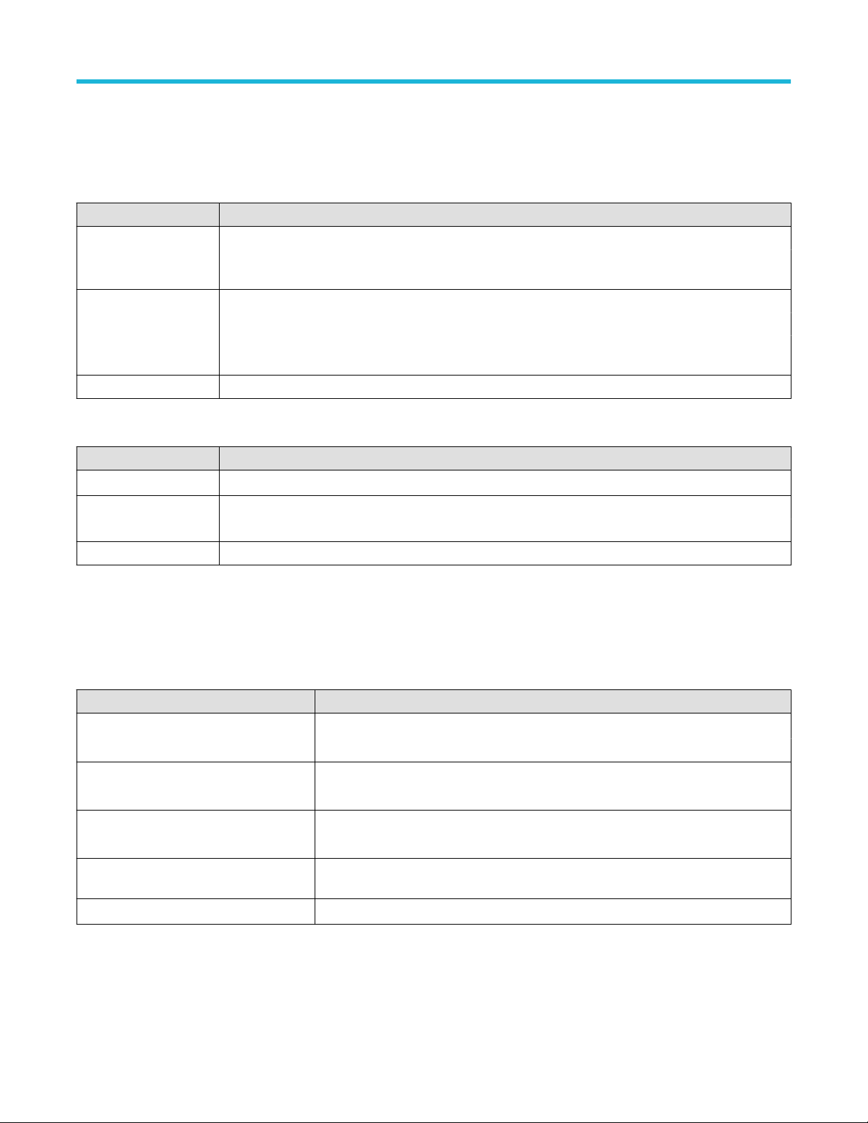
機器のインストール
動作要件
高い測定精度と安全な機器動作を確保するために、動作温度、電力、高度、信号入力電圧の各必須範囲内で本機
を使用してください。
表 1 : 環境要件
特性 説明
動作温度 0℃~+ 50℃(+ 32 ゚F~+ 122 ゚F)
正しく冷却するために、本機の側面と背面から 2 インチ
ないでください。
動作湿度 + 40℃(+ 104°F)以下で相対湿度 5%~90%(RH)(結露のない状態)
+ 40℃(+ 104°F)~+ 50℃(+ 122°F)で相対湿度 5%~55%(RH)(結露のない状態)
+ 60℃(+ 140°F)以下で相対湿度 5%~90%(RH)、結露のないこと、最高湿球温度+
39℃(+ 102°F)
動作高度 3,000m(9,842 フィート)以下
表 2 : 電力要件
特性 説明
電源電圧 100V~240V
電源周波数 50/60Hz、100~240V
400Hz、1
15V
消費電力 400W(最大)
、±10%、単相
AC RMS
(51mm)の範囲には障害物を置か
入力信号要件
入力信号を許容制限内に収めることで、正確な測定を確保し、アナログとデジタルのプローブまたは機器への損
傷を防ぎます。
本機に接続されている入力信号が以下の要件の範囲内であることを確認します。
入力 説明
アナログ入力チャンネル、1MΩ、BNC
で最大入力電圧
アナログ入力チャンネル、50Ω 設定、
BNC で最大入力電圧
デジタル入力チャンネル、デジタル
入力での最大入力電圧レンジ
Ref In(基準入力)
、BNC での最大入力
電圧(後部パネル)
Aux In トリガ入力 ±5V
300V
RMS
測定カテゴリ II
5V
、100mV/div、ピークは≦±20V(パルス幅≦200μ
RMS
測定カテゴリ II
プローブ定格表記の確認
TLP058 型、±42V
7V
PP
RMS
P
s)
5 シリーズ B ミックスド・シグナル・オシロスコープ MSO54B 型、MSO56B 型、MSO58B 型 クイック・スタート・
マニュアル 16
Page 83

機器のインストール
機器の固定(ロック)
プロパティの損失を防ぐために、機器をテスト・ベンチや設備ラックにロックします。
標準的なノートパソコン用セキュリティ・ロックを機器の後部パネルに取り付けて、機器を作業台やラック、そ
の他の場所に固定します。
機器の電源を入れる
この手順では、本機をライン電源に接続し、電源の投入と遮断を行います。本機を AC 電源に接続する時には必
ず、本機に同梱されている電源コードを使用してください。
前提条件:本機に同梱されている AC 電源コードを使用してください。
1. 付属の電源コードを後部パネルの電源コネクタに接続します。
図
1 :
電源コード・コネクタと電源スタンバイ・スイッチ
2. 電源コードを適切な AC 電源に接続します。
AC 電源コードが導通状態の電源回路に接続されると、電力が電源供給部とその他の基盤に供給され、本機が
Standby(スタンバイ)モードに入ります。
3. 本機の電源をオンまたはオフにするには、前面パネルの電源ボタンを押します。
電源ボタンのカラー・インジケータで本機の電源状態を知ることができます。
• 消灯 – AC 電力が投入されてない
• 黄色 – スタンバイ・モード
• 青 – 電源オン
4. 本機の電源を完全に切るには、電源コードを抜きます。
5. 電源コードを含む本機を移動する場合には、後部パネルの上端の電源コード支持具を引き出し、電源コードを
支持具に巻き付けてください。
5 シリーズ B ミックスド・シグナル・オシロスコープ MSO54B 型、MSO56B 型、MSO58B 型 クイック・スタート・
マニュアル 17
Page 84

機器のインストール
パワーオン・セルフ・テストでの機器の合格の確認
パワーオン・セルフ・テストでは、機器の全機種が起動後に正常に作動するかを確認します。
手順
1. 機器の電源をオンにし、機器の画面が表示されるまで待機します。
2. 上端のメニュー・バーで Utility(ユーティリティ)> Self Test(セルフ・テスト)を選択し、Self Test(セルフ・
テスト)のコンフィグレーション・メニューを開きます。
3. すべてのパワーオン・セルフ・テストのステータスが Passed(合格)になっていることを確認します。
いずれかのパワーオン・セルフ・テストの結果が Failed(不合格)と表示されている場合:
1. 機器の電源を入れ直します。
2. Utility(ユーティリティ) > Self Test(セルフ・テスト)をタップします。それでもいずれかのパワーオン・セ
ルフ・テストの結果が Failed(不合格)と表示される場合には、当社カスタマ・サポートに問い合わせてくだ
さい。
プローブの機器への接続
プローブは機器を被測定デバイス(DUT)に接続します。プローブは信号測定のニーズに最適なものを使用してく
ださい。
TPP シリーズ、TekVPI+、TekVPI、またはサポートされているその他の当社アナログ・プローブを FlexChannel コネク
タに挿入して接続します。プローブは完全に挿入されると、プローブのベース・ラッチがカチッと音を立ててロ
ックされます。
TekVPI プローブについては、このプローブのチャンネル入力パラメータ(帯域幅、減衰比、ターミネーションな
ど)が自動で設定されます。プローブに Menu(メニュー)ボタンがある場合、そのボタンを押してスクリーン上
のコンフィグレーション・メニューを開きます。アクティブなプローブの取扱説明書に従ってパラメータ(オー
トゼロ、デガウスなど)を設定します。
TLP058 FlexChannel ロジック・プローブの接続方法
1. ロック・レバーをアンロック位置に移動させ、ロック・レバーが中央に戻るまで待ちます。
2. FlexChannel コネクタにプローブを挿入し、プローブが完全に挿入されてロック・メカニズムのカチッという音
がするまで押し込みます。
3. ロック・レバーをロック位置に移動させます。ステータス・ライトが緑色に点灯します。
4. TLP058 プローブを取り外すには、ロック・レバーをアンロック位置に移動させたままプローブを引き抜きま
す。プローブを取り外している時にリボン・ケーブルを引っ張らないでください。
BNC のプローブまたはケーブルをチャンネル BNC 差し込みコネクタに挿入して接続し、ロック・メカニズムがロ
ックされるまで時計回りに回します。
注 : プローブを接続しても、
プローブまたはケーブルの設定(帯域幅、減衰、ターミネーションなど)の確認や変更を行うには、チャ
ンネル(Channel)バッジを 2 回タップしてそのコンフィグレーション・メニューを開きます。
そのチャンネルは自動的に有効にはなりません(アクティブにしてください)。
5 シリーズ B ミックスド・シグナル・オシロスコープ MSO54B 型、MSO56B 型、MSO58B 型 クイック・スタート・
マニュアル 18
Page 85
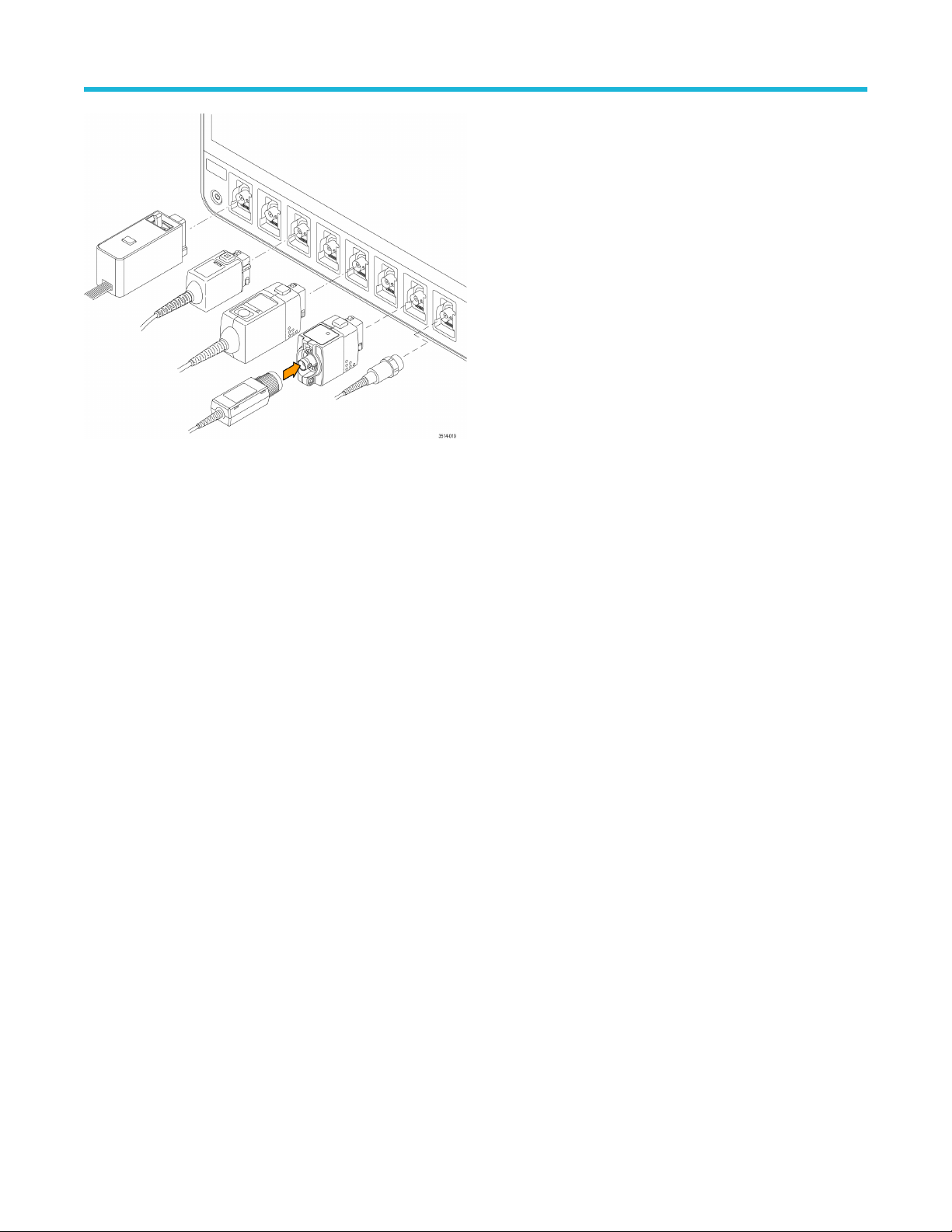
機器のインストール
ラックマウント・オプションに関する情報
オプションのラックマウント・キットを使用すると、標準的な設備ラックにオシロスコープを取り付けることが
できます。
ラックマウント・オプションの詳細ついては、当社 Web サイト(www.tek.com)の製品のデータ・シートを参照し
てください。
5 シリーズ B ミックスド・シグナル・オシロスコープ MSO54B 型、MSO56B 型、MSO58B 型 クイック・スタート・
マニュアル 19
Page 86

機器の詳細
機器の詳細
前面パネル・コントロールおよびコネクタ
前面パネルのコントロールを使うと、垂直軸、水平軸、トリガ、カーソル、ズームなどといった主要機器設定に
直接アクセスできます。これらのコネクタは、プローブまたはケーブルで信号を入力した位置か、または USB デ
バイスを挿入した位置にあります。
注 : コントロールを使用した波形の表示および測定の実施に関する詳細については、本機のヘルプを参照
してください。
図
2 : 5
シリーズ
1. Acquisition(アクイジション)コントロールと Cursors(カーソル)コントロール:
• Run/Stop(実行/停止)は、波形の取込みの開始と停止を行う機能です。ボタンの色はアクイジションの
• Cursors(カーソル)ボタンはスクリーン・カーソルをオンまたはオフにする機能です。カーソルを移動さ
• Fast Acq™は Fast acquisition(高速アクイジション)モードの有効化と無効化を行う機能です。FastAcq では、
• Single/Seq(単発/連続)を使うと、単発の波形アクイジションや、指定した回数のアクイジションを実行
5 シリーズ B ミックスド・シグナル・オシロスコープ MSO54B 型、MSO56B 型、MSO58B 型 クイック・スタート・
マニュアル 20
B MSO
のコントロール
ステータスを示します(緑色=アクイジション実行中、赤色=停止)。停止時、オシロスコープには最後
に完了したアクイジションの波形が表示されます。スクリーン上の Run/Stop(実行/停止)ボタンにもア
クイジション・ステータスが表示されます。
せるには汎用ノブを使用します。カーソルのタイプと機能を設定するには、カーソルのリードアウトをダ
ブルタップするか、またはカーソル・バー(ライン)上をダブルタップして、コンフィグレーション・メ
ニューを開きます。
波形のアクイジションが行われる間のデッド・タイムが短縮されるため、グリッチやラント・パルスなど
の過渡的イベントであっても、取り込み、表示することができます。捉えるのが困難な信号異常の検出に
役立ちます。また、高速アクイジション(Fast Acquisition)モードでは、発生頻度に応じた輝度で波形現象
を表示できます。
できます(Acquisition(アクイジション)のコンフィグレーション・メニューで設定)。Single/Seq(単発/
連続)を押すと Run/Stop(実行/停止)モードがオフになり、単発のアクイジションが実行されます。ボ
タンの色はアクイジションのステータスを示します(緑色の高速点滅=単発アクイジション実行、緑色の
Page 87

機器の詳細
点灯=トリガ・イベント待ち)。もう一度 Single/Seq(単発/連続)
行されます。
• High Res(ハイレゾ)は、現在のサンプル・レートに基づいて固有の有限インパルス応答(FIR)フィルタ
を適用します。この FIR フィルタは、そのサンプル・レートに対する可能な最高帯域幅を維持しながら、
エイリアシングを排除します。このフィルタは、オシロスコープの増幅器と ADC から、選択したサンプ
ル・レートに対する使用可能帯域幅を上回る雑音を除去します。トリガやストレージよりも前にフィルタ
をハードウェアに実装しておくと、トリガ・ジッタを低下させることができ、Fast Acq(高速アクイジシ
ョン)モードと High Res(ハイレゾ)モードを同時に使用できます。
High Res(ハイレゾモード)ではさらに、少なくとも 12 ビットの垂直分解能が保証されます。分解能のビ
ット数はスクリーン下部の Acquisition(アクイジション)バッジに表示されます。Horizontal(水平軸)バ
ッジは、 High Res(ハイレゾ)モードの時に更新されると、サンプル・レートとレコード長さの設定がバ
ッジに表示されます。
• Clear(クリア)は現在のアクイジションと測定値をメモリから消去する機能です。
2. 汎用ノブ:汎用ノブ A および B は、カーソルを移動する場合、コンフィグレーション・メニューの入力ボッ
クス内でパラメータ値を設定する場合に使用します。汎用ノブを使用できる入力ボックスを選択すると表示
されたノブが割り当てられ、そのノブでその入力ボックス内の値を変更できます。各ノブは、アクションの
実行に使用できる時にリングが点灯します。汎用ノブを押すと、増分変化が小さい Fine(微調整)モードが
有効になります。Fine(微調整)モードを終了するには、そのノブをもう一度押します。
3. Trigger(トリガ)コントロール:
• Force(強制)は、波形の任意のポイントでトリガ・イベントを強制し、アクイジションをキャプチャする
機能です。
• Level(レベル)は、信号が通過する時の振幅レベルが有効なトランジションとみなされるように設定する
機能です。Level(レベル)ノブの LED の色は、デュアルレベルのトリガ以外のトリガ・ソースを示しま
す。
を押すと別の単発アクイジションが実
トリガ・タイプに対して 2 つのレベル設定またはその他のトリガ・クオリファイアが必要なときに(Trigger
(トリガ)のコンフィグレーション・メニューから設定する)、Level(レベル)ノブは無効です。このノブ
を押して、スレッショルド・レベルを信号の p-p 振幅範囲の 50%に設定します。
• Slope(スロープ)は検出する信号トランジションの方向(低~高、高~低、または一方方向)を設定する
機能です。選択を繰り返すにはこのボタンを押します。トリガ・タイプに対して別のスロープ・クオリフ
ァイアが必要なときには(Trigger(トリガ)のコンフィグレーション・メニューから設定する)、Slope(ス
ロープ)ボタンは無効です。
• Mode(モード)は、トリガ・イベントの有無による機器の挙動を設定するための機能です。
• Auto(オート)トリガ・モードでは、トリガ・イベントの発生の有無に関係なく、本機での波形のアク
イジションと表示が可能です。トリガ・イベントが発生した場合には、安定した波形が表示されます。
トリガ・イベントが発生しない場合には、本機がトリガ・イベントを強制的に発生させ、不安定な波
形が表示されます。
• Normal(ノーマル)トリガ・モードでは、有効なトリガ・イベントが存在するときのみ波形のアクイジ
ションと表示が行われるように、本機が設定されます。トリガが発生しない場合は、前に取り込んだ
波形レコードがそのまま表示されます。前の波形がない場合、波形は表示されません。
4. Vertical(垂直軸)コントロール:
• Position(位置)は、選択した波形(チャンネル、演算、リファレンス、バス)やその目盛をスクリーン上
で上下に移動させる機能です。Position(位置)ノブの色は、このノブで制御している波形を示していま
す。このノブを押して、スレッショルド・レベルを信号の p-p 振幅範囲の 50%に設定します。
• Scale(スケール)は、選択した波形の垂直目盛区分ごとに振幅単位を設定する機能です。スケール値は、
水平目盛ラインの右端に表示され、Stacked(スタック)モードの場合も Overlay(オーバーレイ)モード
の場合も選択した波形に固有のものです(言い換えれば、ディスプレイのモードに関係なく、各波形には
固有の垂直目盛設定があるということ)。Scale(スケール)ノブの色は、このノブで制御している波形を
示しています。
5 シリーズ B ミックスド・シグナル・オシロスコープ MSO54B 型、MSO56B 型、MSO58B 型 クイック・スタート・
マニュアル 21
Page 88

機器の詳細
• Channel(チャンネル)ボタンは、チャンネル、演算、リファレンス、またはバス波形をオン(表示)
択、またはオフにします。チャンネル・ボタンの数は機種によって異なります。ボタンは次のように動作
します。
• チャンネルが表示されていない場合にチャンネル・ボタンを押すと、そのチャンネルが波形表示に表
示されます。
• チャンネルがスクリーン上になく、選択されていない場合、そのチャンネルのボタンを押すとそのチ
ャンネルが選択されます。
• チャンネルがスクリーン上にあって選択されている場合、そのチャンネルのボタンを押すと、そのチ
ャンネルがオフ(波形ビューから削除)になります。
• Math(演算)ボタンを使うと、次のように波形ビュー上での演算波形の追加や選択を実行できます。
• 演算波形がない場合、Math(演算)ボタンを押すと波形ビューに演算波形が追加され、Math(演算)の
コンフィグレーション・メニューが開きます。
• 演算波形が 1 つだけ表示されている場合、このボタンを押すと演算波形がオフ(波形表示から削除)に
なります。波形を表示するにはこのボタンをもう一度押します。
• 複数の演算波形が表示されている場合、このボタンを押すと各演算波形の選択が繰り返されます。
• Ref(リファレンス)ボタンを使うと、次のように波形ビュー上でのリファレンス(保存)波形の追加や選
択を実行できます。
• リファレンス波形が存在しない場合、Ref(リファレンス)ボタンを押すと、Browse Waveform Files(波
形ファイルの参照)の設定メニューが表示されます。波形ファイル(*.wfm)を見つけて選択し、Recall
(呼出)をタップすると、リファレンス波形がロードされて表示されます。
• リファレンス波形が 1 つだけ表示されている場合、このボタンを押すとリファレンス波形がオフ(波形
ビューから削除)になります。波形を表示するにはこのボタンをもう一度押します。
• 複数のリファレンス波形が表示されている場合、このボタンを押すと各リファレンス波形の選択が繰
り返されます。
• Bus(バス)ボタンを使うと、次のように波形ビュー上でのバス波形の追加や選択を実行できます。
、選
• バス波形がない場合、Bus(バス)ボタンを押すと波形ビューにバス波形が追加され、Bus(バス)のコ
ンフィグレーション・メニューが開きます。
• バス波形が 1 つだけ表示されている場合、このボタンを押すとバス波形がオフ(波形ビューから削除)
になります。
• 複数のバス波形が表示されている場合、このボタンを押すと各バス波形の選択が繰り返されます。
5. Horizontal(水平軸)コントロール:
• Position(位置)は、波形や目盛をスクリーン上で左右に移動させる(波形レコードのトリガ・ポイントの
位置を変更する)機能です。このノブを押すと、トリガ・イベントが波形表示上の中央の目盛に移動しま
す。
• Scale(スケール)は、オシロスコープの主要水平目盛区分ごとの時間パラメータとサンプル数/秒パラメー
タを設定する機能です。Scale(スケール)はすべての波形に適用されます。このノブを押すと、増分変化
が小さい Fine(微調整)モードが有効になります。Fine(微調整)モードを終了するには、そのノブをも
う一度押します。
• Zoom(ズーム)を使うと Zoom(ズーム)モードが開きます。Zoom(ズーム)をもう一度押すと Zoom(ズ
ーム)モードが閉じます。
• Zoom(ズーム)ノブ(中央のノブ)を使うと、Zoom Waveform Overview(ズーム波形の概観)のズーム・ボ
ックスの面積の拡大と縮小、メインのズーム・ビューに表示される波形のズーム量の制御を実行できま
す。
• Pan(パン)ノブ(外側のノブ)は、Zoom Waveform Overview(ズーム波形の概観)内でのズーム・ボック
スの左右移動、メインのズーム・ビューに表示される波形の一部の制御を実行できます。
• ナビゲートボタン(左右の矢印)を使うと、オシロスコープが Zoom(ズーム)モードになり、波形レコー
ドの検索の「戻る」ポイントまたは「進む」ポイントの位置を波形表示の中央目盛に移動させることがで
5 シリーズ B ミックスド・シグナル・オシロスコープ MSO54B 型、MSO56B 型、MSO58B 型 クイック・スタート・
マニュアル 22
Page 89

機器の詳細
きます。ナビゲート機能を操作する場合には、
要があります。前面パネルのナビゲート・ボタンを長押しすると、その方向の次の検索ポイントに移動し
ます。
前面パネルのナビゲートボタンは、測定バッジの「戻る」ボタンと「進む」ボタンの機能として使用する
こともできます。
6. その他のコントロール:
• Touch Off(タッチ・オフ)を有効にするとタッチ・スクリーン機能がオフになります。タッチ・スクリー
ンがオフになると Touch Off(タッチ・オフ)ボタンが点灯します。
• Save(保存)を使用すると、ボタンを 1 回押すだけで、現在の File(ファイル)> Save As(名前を付けて
保存)の設定を使用して、スクリーン・ショット(オープン・メニューとダイアログ・ボックスを含む)、
波形ファイル、機器設定などを保存できます。
• 機器を前回起動した後に、File(ファイル) > Save(保存)または File(ファイル) > Save As(名前を
付けて保存)の操作が行われている場合には、Save(保存)を押すと、前回 Save As(名前を付けて保
存)のコンフィグレーション・メニューで設定した場所にその種類のファイルが保存されます。
• 機器を前回起動した後にファイル保存操作を行わなかった場合には、Save(保存)を押すと、Save As
(名前を付けて保存)のコンフィグレーション・メニューが開きます。保存するファイルのタイプ(ス
クリーン・キャプチャ、波形など)を選択するためのタブを選択し、関連パラメータと保存先を設定
して、OK を選択します。指定した 1 つまたは複数のファイルが保存されます。次回 Save(保存)を押
すと、同じ種類のファイルが保存されます。
• Screen Captures(スクリーン・キャプチャ)は、表示される多くのコンフィグレーション・メニューや
ダイアログ・ボックスなどを含めたスクリーン全体をキャプチャする機能です。
• Default Setup(工場出荷時設定)は、オシロスコープ設定(水平軸、垂直軸、スケール、位置など)を出荷
時デフォルト設定に戻す機能です。
• Autoset(オートセット)は安定した波形を自動表示する機能です。
7. グランド・コネクタとプローブ補正コネクタ:グランド・コネクタとプローブ補正コネクタは、本機の右下、
前面パネル付近にあります。グランド・コネクタ(ケース内の小さな穴)は、(レジスタを通じて)電気的に
接地された接続ポイントで、DUT の取り扱い時または精査時に静電気損傷(ESD)を防ぐための静電気防止リ
スト・ストラップをこの接続ポイントに取り付けます。
事前に結果バーに Search(検索)バッジを表示しておく必
プローブ補正用接続部には、グランド・コネクタ(上側のタブ)と 1kHz の方形波ソース(下側のタブ)があ
り、受動プローブの高周波数応答の調整(プローブ補正)に使用します。オシロスコープはこの信号を利用
して、サポートされているプローブ(本製品に同梱されているプローブを含む)の自動補正を行います。
8. USB ホスト・ポート(USB3.0 と 2.0):USB ポートは前面パネルの右下と後部パネルにあります。データ(機
器のソフトウェア更新、波形、設定、ディスプレイ取込みなど)の保存や呼出が可能な USB フラッシュ・ド
ライブを接続するか、またはマウスやキーボードなどの周辺機器を接続してください。
9. FlexChannel プローブ・コネクタ:FlexChannel コネクタは、TekVPI+測定プローブ、TekVPI 測定プローブ、BNC
受動プローブ、TPL058 FlexChannel ロジック・プローブ、BNC ケーブルのすべてに対応しています。プローブ
の接続は簡単で、プローブをカチッと音がするまでしっかりとコネクタに押し込むだけです。
10. Aux Trig トリガ入力コネクタ:外部トリガの入力信号を接続できる SMA コネクタ。Aux In トリガ信号はエッ
ジ・トリガ・モードを指定して使用します。
5 シリーズ B ミックスド・シグナル・オシロスコープ MSO54B 型、MSO56B 型、MSO58B 型 クイック・スタート・
マニュアル 23
Page 90

機器の詳細
後部パネルの接続部
後部パネルの接続部は、本機への電源供給と、ネットワーク、USB デバイス、ビデオ、リファレンス信号、AFG 出
力の接続のために使用します。
1. 電源コード・コネクタ:本製品用に指定され、使用される国で認定された電源コードのみを使用してください。
2. Ref In:高精度 10MHz リファレンス信号をオシロスコープに接続して測定の精度を確保します。
3. AUX Out:トリガ・イベントで信号トランジションを生成し、10MHz のリファレンス信号を出力、または AFG か
ら同期信号を出力します。
4. AFG Out は、オプションの任意波形/ファンクション・ジェネレータ(AFG)用の信号出力です。
5. ビデオ出力(Display Port、VGA、DVI-D):外部のモニタまたはプロジェクタに接続して本機のグラフィカル・ユ
ーザ・インタフェースの画面を表示します。
6. USB 3.0 デバイス・ポートにより、USBTMC プロトコルを使用して本機を遠隔操作する場合に PC に接続します。
7. USB ホスト・ポート:USB メモリ・デバイス、キーボード、またはマウスを接続します。
8. LAN コネクタ(RJ-45)は、本機を 10/100/1000 Base-T ローカル・エリア・ネットワークに接続します。
9. セキュリティ・ロック・コネクタにより、標準的な PC およびノートパソコン用のロック・ケーブルを使用し
て、本機を作業台やその他の場所に固定します。
5 シリーズ B ミックスド・シグナル・オシロスコープ MSO54B 型、MSO56B 型、MSO58B 型 クイック・スタート・
マニュアル 24
Page 91

機器の詳細
ユーザ・インタフェース
タッチ・スクリーン式のユーザ・インタフェースには、波形、プロット、測定リードアウト、オシロスコープの
全機能にアクセスできるタッチベースのコントロールが含まれています。
注 : ユーザ・インタフェースを使用した波形の表示および測定の実施に関する詳細については、本機のヘ
ルプを参照してください。
1. メニュー・バーには次の通常処理用メニューが含まれます。
• 保存ファイル、ロード・ファイル、アクセス・ファイル
• 動作の取り消し、動作の再実行
• オシロスコープのディスプレイ設定と測定設定の決定
• ネットワークアクセスの構築
• セルフ・テストの実施
• 測定と設定メモリ(T
• オプション・ライセンスのロード
• Help(ヘルプ)ビューアの操作
2. 波形表示領域には、アナログ波形、デジタル波形、演算波形、リファレンス波形、バス波形、トレンド波形が
表示されます。波形には、波形ハンドル(識別子)、個別の垂直目盛スケールのラベル、トリガ位置、ラベル表
示が含まれます。”スライス”と呼ばれる形式(デフォルト・モード。前のイメージに示す)で各波形が個別の目
盛に縦に積み重なって表示されるように、またはスクリーンにすべての波長が重ね合わさって表示されるよう
に、波形表示を設定できます。
個別の測定に対して、ヒストグラム(Histogram)表示、スペクトル(Spectral)表示、アイ(Eye)表示、測定結果
(Measurement Results)表示(プロット)も追加できます。これらのプロットは個別の表示ウィンドウを持ってお
り、それぞれのタイトル・バーを新たな位置にドラッグすることで、スクリーン上で移動させることができま
す。
ekSecure™)の消去
ユーザ・インタフェース要素
(27 ページ)を参照してください。
5 シリーズ B ミックスド・シグナル・オシロスコープ MSO54B 型、MSO56B 型、MSO58B 型 クイック・スタート・
マニュアル 25
Page 92

機器の詳細
3. 結果バーには、カーソルの表示、スクリーンへのコールアウトやプロットや結果表の追加、結果バーへの測定
の追加を実行するコントロールがあります。結果バーから測定、
画面の外にフリックします。具体的には以下の通りです。
• Cursors(カーソル)ボタンを使用すると、選択したビューにオンスクリーン・カーソルを表示できます。
Multipurpose(汎用)ノブをタッチしてドラッグするか、使用すると、カーソルを移動できます。カーソルま
たはカーソルのリードアウトをダブルタップすると、コンフィグレーション・メニューが開き、カーソルの
タイプや関連機能を設定できます。
• Measure(測定)ボタンを使うと、コンフィグレーション・メニューが開き、そこから測定を選択して結果
バーに追加できます。追加する各測定には個別のバッジがあります。測定バッジをダブルタップすると、そ
のコンフィグレーション・メニューが開きます。
• Results Table(結果表)ボタンを使うと、Measurement Results(測定結果)表または Bus Results(バス結果)表
をスクリーンに追加できます。Measurement Results(測定結果)表には、結果バーに存在するすべての測定が
表示されます。Bus Results(バス結果)表には、表示されているバス波形に関するバス・デコード情報が表
示されます。各表は固有のビュー・ウィンドウに表示され、ディスプレイ領域内を移動させることができま
す。
• 結果バーから測定、検索、またはその他のバッジを削除するには、画面の外にフリックします。
• Callout(コールアウト)ボタンを使用すると、選択したビューにコールアウト・オブジェクトを追加できま
す。コールアウト・テキストをダブルタップするとコンフィグレーション・メニューが開き、コールアウト
の種類やテキスト、フォントの特性を変更できます。ブックマーク以外のコールアウトは、オシロスコープ
の画面ビュー上の任意の場所にドラッグできます。ブックマーク・コールアウトは、波形ビューとスペクト
ラム・ビューにしか追加できません。
• Search(検索)ボタンを使うと、指定したイベントが発生している波形を検出してマークできます。Search
(検索)をタップすると Search(検索)コンフィグレーション・メニューが開き、アナログ・チャンネルと
デジタル・チャンネルの検索条件を設定できます。同じ波形または異なる波形に検索をいくらでも追加でき
ます。Search(検索)バッジが結果バーに追加されます。
• Plot(プロット)ボタンを使うと、XY プロット、XYZ プロット、または Eye Diagram (アイ・ダイアグラム)
プロットをディスプレイに追加できます。これらのプロットは、それぞれのウィンドウに含まれ、ディスプ
レイ領域全体で移動させることができます。
• Measurement(測定)バッジと Search(検索)バッジは、測定結果と検索結果を示し、結果(Results)バー
に表示されます。
い。
検索の追加
• 結果バーの右側のズーム・アイコンボタンを使用することで、画面にボックスを描画して、目的の領域を拡
大したり、マーク・テストのセグメントやビジュアル・トリガの条件を定義するトリガ領域を描画できま
す。
• More...(その他...)ボタン(結果バーの右上)を使用することで、ズーム、ビジュアル・トリガ、またはマ
スクを選択できます。
4. 設定バーには、水平軸パラメータ、トリガ・パラメータ、アクイジション・パラメータ、日付/時刻パラメー
タを設定できるシステム・バッジ、無効チャンネルをオンにするチャンネル・ボタン、演算波形、リファレン
ス波形、バス波形をディスプレイに追加する波形の Add New(新規追加)ボタン、波形パラメータを個別に設
定できるチャンネル/波形バッジがあります。チャンネル・ボタンまたは波形ボタンをタップすると、チャン
ネルまたは波形がスクリーンに追加されてバッジが表示されます。バッジを 2 回タップすると、そのコンフィ
グレーション・メニューが開きます。
バッジ
(58 ページ)を参照してください。
(29 ページ)を参照してください。
検索、またはその他のバッジを削除するには、
測定の追加
(53 ページ)を参照してくださ
バッジ
5. Configuration Menus(コンフィグレーション・メニュー)を使うと、選択したユーザ・インタフェース項目のパ
ラメータを簡単に変更できます。コンフィグレーション・メニューは、バッジ、スクリーン・オブジェクトま
たはスクリーン領域を 2 回タップすれば開きます。
てください。
5 シリーズ B ミックスド・シグナル・オシロスコープ MSO54B 型、MSO56B 型、MSO58B 型 クイック・スタート・
マニュアル 26
(29 ページ) を参照してください。
コンフィグレーション・メニュー
(38 ページ)を参照し
Page 93

機器の詳細
ユーザ・インタフェース要素
ユーザ・インタフェースの各領域には、情報やコントロールの管理に役立つ特殊機能があります。このトピック
では、ユーザ・インタフェースの主要要素を示して説明します。
1. 波形レコード・ビューは、波形レコードの全長、スクリーンに表示されている波形レコードの量(カッコ内
に表示)
ルなビューです。
現在のアクイジションのレコード長全体よりも短いリファレンス波形を表示している場合、またはオシロス
コープでのアクイジションの停止時に水平軸時間スケールを変更している場合、現在のアクイジション・レ
コード長さに関連して表示されている波形レコードの一部が表示されるようにカッコの位置が変更されま
す。
波形上でカーソルがアクティブである場合、波形レコード・ビューには小さな垂直破線として関連カーソル
位置が表示されます。
Zoom(ズーム)
ス
2. 波形ビューの拡張ポイントアイコンは、水平軸設定を変更するときの波形の拡張と圧縮の中心点を示します。
、トリガ・イベントを含む主要時間イベントの場所、波形カーソルの現在の位置を図示したハイレベ
モードのとき、波形レコード・ビューはズーム概観になります。Zoom
(39 ページ)を参照してください。
ユーザ・インタフェー
5 シリーズ B ミックスド・シグナル・オシロスコープ MSO54B 型、MSO56B 型、MSO58B 型 クイック・スタート・
マニュアル 27
Page 94

機器の詳細
3. トリガ位置インジケータは波形レコードで発生したトリガイベントの位置を示します。このトリガ・アイコ
ンは、トリガ・ソースである波形スライスに表示されます。
4. ズーム・アイコン(波形ビューとプロット・ビューの右上にある)を使うと、ズームのオンとオフを切り替
えることができます。前面パネルの Zoom(ズーム)ボタンとノブを使うと、Zoom(ズーム)モードをオンに
してズーム・ボックスの位置と横幅を変更することもできます。
5. トリガ・レベル・インジケータ・アイコンは、トリガ・ソース波形上のトリガ・レベルを示します。一部の
トリガ・タイプに対しては、トリガ・レベルが 2 つ必要です。
バッジ
バッジ
(29 ページ)
(29 ページ)
6. Measurement(測定)/Search(検索)バッジはそれぞれ測定結果と検索結果を示します。
を参照してください。
7. 結果バー・ハンドルは結果バーを開閉する機能で、必要に応じて波形スクリーンの表示を最大化できます。
結果バーをもう一度開くには、このハンドル・アイコンをタップするか、ディスプレイの右側から左に向か
ってスワイプします。
8. System(システム)バッジを使うと、機器のグローバル設定(Horizontal(水平軸)、Trigger(トリガ)、Acquisition
(アクイジション)、Run/Stop(実行/停止)ステータス、Date/Time(日時))を表示できます。
を参照してください。
9. Inactive Channel(無効チャンネル)ボタンを使うと、チャンネル波形を波形ビューに、関連するチャンネル・
バッジを設定バーに追加できます。
測定の追加
(53 ページ)を参照してください。
Add New Math(新規演算を追加)、Add New Ref(新規参照の追加)、Add New Bus(新規バスの追加)ボタンを
使うと、対応する信号を波形ビューに追加し、さらに関連する波形バッジを Settings(設定)バーに追加でき
ます。演算波形やリファレンス波形やバス波形の追加はシステム・メモリによってのみ可能です。
オプションの AFG ボタンを使うと、AFG コンフィグレーション・メニューを開いて AFG 出力を設定し、それ
を有効化できます。このボタンが存在するのは、AFG オプションがインストールされている場合に限ります。
オプションの DVM ボタンを使うと、アナログ・プローブを使って DUT 上で DC 電圧測定、AC RMS 電圧測定、
または DC+AC RMS 電圧測定を実施できます。このボタンをタップして DVM バッジを結果(Results)バーに追
加し、コンフィグレーション・メニューを開きます。DVM オプションを使うと、Trigger (トリガ)バッジ・
メニューの Mode & Holdoff(モード&ホールドオフ)パネルからトリガ周波数カウンタにアクセスして有効化
することもできます。このボタンが存在するのは、DVM オプションがインストールされている場合に限りま
す。
10. バッジをダブルタップすると、そのコンフィグレーション・メニューが開きます。
照してください。
Channel(チャンネル)バッジまたは Waveform(波形)バッジを追加して、波形バッジ領域に納まりきらなく
なった場合には、波形バッジ表示領域の両端にあるスクロール・ボタンをタップし、スクロールすることで、
隠れているバッジを表示させることができます。
11. それぞれの波形の波形ハンドルによって、その波形のソースを識別できます(チャンネルは Cx、演算波形は
Mx、リファレンス波形は Rx、バス波形は Bx)。この波形ハンドルは、デフォルトでは、波形の 0 電圧レベル
にあります。現在選択されている波形ハンドルは着色され、選択されていない波形ハンドルは線のみが表示
されます。
波形ハンドルを 2 回タップするとその波形のコンフィグレーション・メニューが開きます。
デジタル・チャンネルの場合、波形ハンドルにはチャンネル番号と D0~D7 の個別のデジタル信号が異なる色
のラベルで表示されます。
コンフィグレーション・メニュー
(38 ページ)を参照してください。
バッジ
(29 ページ)を参
5 シリーズ B ミックスド・シグナル・オシロスコープ MSO54B 型、MSO56B 型、MSO58B 型 クイック・スタート・
マニュアル 28
Page 95
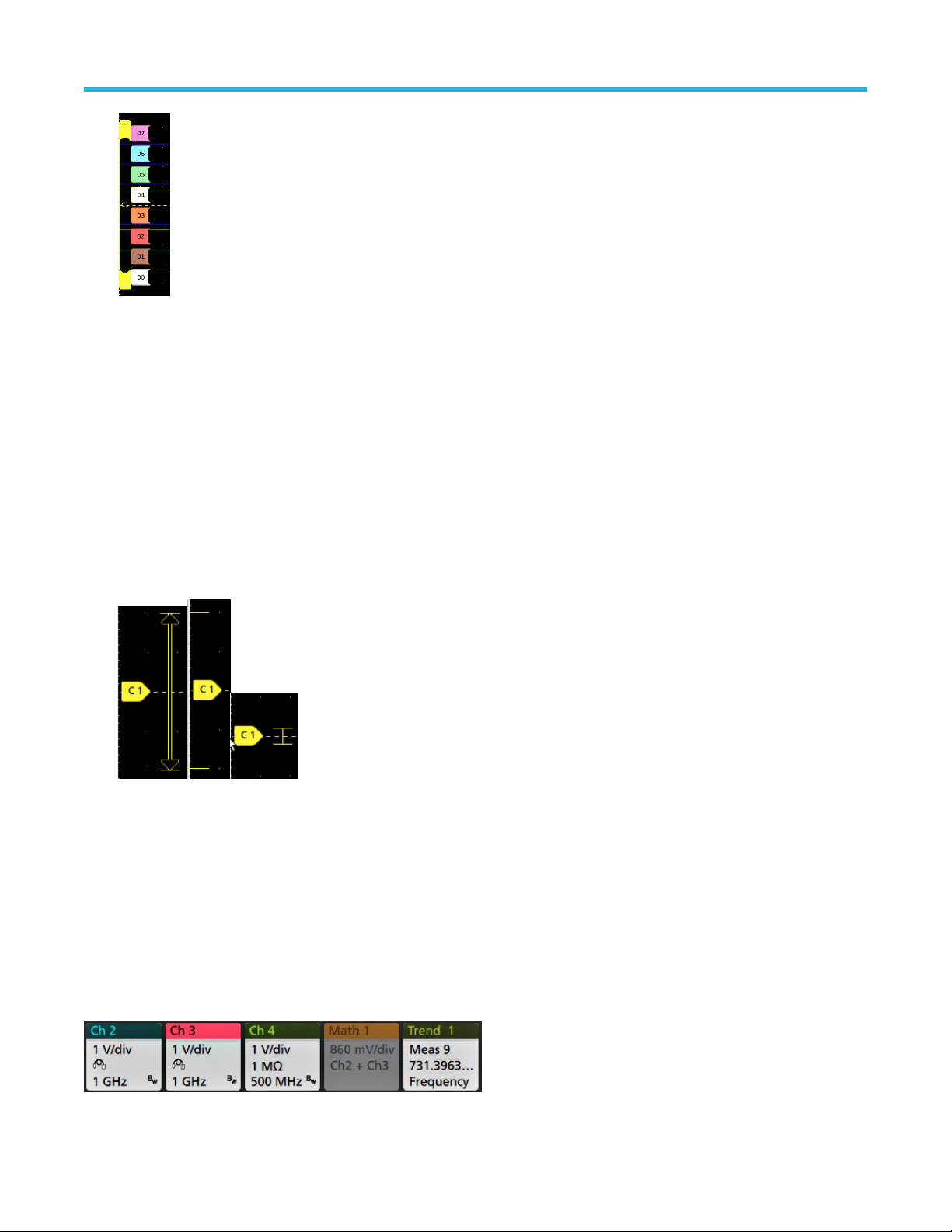
機器の詳細
デジタル波形ハンドルをダブルクリックすると、デジタル・チャンネルのコンフィグレーション・メニュー
が開きます。
デジタル信号ハンドルを別のハンドルにドラッグすると、波形上でこれらの 2 つの信号が入れ替わります。
チャンネルの波形トレースの垂直軸のハンドルの位置に基づいて、目盛の左端のすぐ内側の部分に、プロー
ブのダイナミック・レンジ・リミット・マーカが表示されます。これはプローブのダイナミック・レンジの
制限値に従って上下に伸縮して表示されます。マーカが表示されるのは、対応プローブが使用されている場
合だけです。オシロスコープが正しく表示し、測定できるように、信号はプローブのダイナミック・レンジ
内でなければなりません。
Offset(オフセット)、Position(位置)、または Scale(スケール)のいずれかのコントロールを変更した後に、
チャンネルのダイナミック・レンジのリミットがアクイジション・ウィンドウの範囲内に留まるときに、マ
ーカが約 3 秒間表示されます。約 3 秒経過すると、マーカは短いラインに変化して、目盛の左端に表示され
ます。ダイナミック・レンジが狭く、矢印を表示できない場合には、矢印の表示は省略されます。
3 種類のマーカ表示の例を以下に示します。
バッジ
バッジとは、波形、測定、機器の設定やリードアウトを示す四角形のアイコンです。バッジを使うとコンフィグ
レーション
形)、Measurement(測定)、Search(検索)、および System(システム)があります。
チャンネル・バッジと波形バッジ
チャンネル・バッジと波形バッジ(Math(演算)、Ref(リファレンス)、Bus(バス)、Trend(トレンド))は、ス
クリーン左下の設定バーに表示されます。波形にはそれぞれ固有のバッジがあります。これらのバッジには、表
示されている各チャンネルまたは波形のハイレベルの設定が表示されます。バッジを 2 回タップすると、そのコ
ンフィグレーション・メニューが開きます。
・メニューにもすばやくアクセスできます。バッジのタイプには、Channel(チャンネル)、Waveform(波
5 シリーズ B ミックスド・シグナル・オシロスコープ MSO54B 型、MSO56B 型、MSO58B 型 クイック・スタート・
マニュアル 29
Page 96

機器の詳細
大半のチャンネル(Channel)バッジと波形(W
るとこのボタンが表示されます。Scale(スケール)ボタンを使って、その波形の垂直軸スケール設定を増減させ
ることができます。
チャンネル/波形バッジをドラッグして設定バーの位置を変更したり、バッジの右クリックメニューを開いてク
イックアクションメニューにアクセスしたりすることができます。
チャンネル・バッジおよび波形バッジを削除するには、次の 2 つの方法があります。
• バッジを右クリックしてオフにします。
• ディスプレイの下端からバッジをフリックして設定バーから削除します。設定バーの下端から上にフリック
するとバッジが復元されます。削除後 10 秒以内でなければバッジは復元されません。
Channel(チャンネル)バッジは、ユーザが移動しない限り、チャンネルの番号順に並びます。Channel(チャンネ
ル・バッジ)には、短いエラー/警告メッセージが表示される場合があります。詳細については、バッジをダブ
ルタップしてコンフィグレーション・メニューを開くか、ヘルプを検索してください。
W
aveform(波形)バッジ(演算、Ref、バス、トレンド)は、(ユーザが移動しない限り)作成された順番に並び、
タイプ別にグループ化されます。Waveform(波形)バッジを削除しても、残りの波形バッジの順序や名前は変わり
ません。
aveform)バッジにはスケール(Scale)ボタンがあり、バッジを 1 回タップす
測定バッジ
Measurement(測定)バッジは結果バーにあります。これらのバッジには測定結果や検索結果が表示されます。バ
ッジのタイトルにも測定ソースまたはソースが表示されます。Measurement(測定)バッジを追加するには、Add
New Measurement(測定の新規追加)ボタンをタップして測定を選択します。
Measurement(測定)バッジをダブルタップしてそのコンフィグレーション・メニューを開き、設定内容の変更ま
たは微調整を行います。デフォルトの測定バッジのリードアウトには測定平均値(μ)が表示されます。
一部の測定やそのバッジは、オプション使用時にのみ利用できます。たとえば、必要なパワー・オプションがイ
ンストールされている場合にのみ、新規追加...測定・メニューにパワー測定の項目が表示されます。
ワイド・バッジ:ワイドバッジは、すべての相の測定結果をそれぞれ別の列に表示します。結果バッジの最初の
列には、
して表示されます。各相に設定されたソースがチャンネル・カラーで表示されます。
ワイド・バッジは IMDA の測定にのみ適用されます。
すべての測定項目が記載されています。周波数などの共通結果は、(3)相すべてに適用され、1 つの値と
5 シリーズ B ミックスド・シグナル・オシロスコープ MSO54B 型、MSO56B 型、MSO58B 型 クイック・スタート・
マニュアル 30
Page 97

機器の詳細
個別の測定バッジに統計リードアウトを追加するには、測定バッジを 2 回タップしてコンフィグレーション・メ
ニューを開き、Show Statistics in Badge(統計値をバッジに表示)を選択します。測定バッジには、標準偏差(σ)
の値が表示されます。ポピュレーションが 1 のとき、標準偏差は 0 です。
一部の測定バッジにはナビゲーション(Navigation)ボタンもあり、それはバッジを 1 回タップすると表示されます。
<(戻る)ボタンと>(進む)ボタンを使うと、
ドの前の測定点と次の測定点の位置で波形がディスプレイの中央に表示されます。
ナビゲーション・ボタンである Min'(最小)と Max'(最大)と使うと、現行のアクイジションにおけるその測定の
最小値または最大値で波形がディスプレイの中央に表示されます。
測定の読み値と最小/最大(Min/Max)ボタンに表示されているダッシュ記号(')は、表示されている値(または最小
(Min)/最大(Max)ボタンおよび波形の場合にはこれらの位置に移動される)が現行アクイジションに由来する値で
あることを示しています。ダッシュ記号がついていない値は、すべてのアクイジションに由来する値であること
を意味します。
測定バッジには、設定メニューで合否判定が有効になっている場合、Status(ステータス)と Failures(エラー)
の情報が表示されます。ステータス・ラインには、Pass/Fail Testing(パス/フェイル・テスト)パネルで定義され
た条件に従って、Pass(緑)または Fail(赤)が表示されます。バッジに統計情報が表示されている場合は、フェ
イル数が表示されます。パス/フェイル・ステータス、フェイル数、パス/フェイル・テスト・パネルで設定さ
れたリミットは、測定結果表で確認できます。
(1 回のアクイジションに複数回実施される測定に関して)レコー
5 シリーズ B ミックスド・シグナル・オシロスコープ MSO54B 型、MSO56B 型、MSO58B 型 クイック・スタート・
マニュアル 31
Page 98

機器の詳細
測定バッジは作成順に並び、結果のバーの上部から始まります。測定バッジを削除しても、残りの波形バッジの
順序や名前は変わりません。
測定バッジをドラッグして結果バーの位置を変更したり、バッジの右クリックメニューを開いてクイックアクシ
ョンメニューにアクセスしたりすることができます。
チャンネル・バッジおよび波形バッジを削除するには、次の 2 つの方法があります。
• バッジを右クリックしてオフにします。
• ディスプレイの右端からバッジをフリックして結果バーから削除します。ディスプレイの右端から左にフリ
ックすると結果バーが復元されます。削除後 10 秒以内でなければバッジは復元されません。
マスク・テスト・バッジ
マスク・テストの結果と測定統計情報は、結果バーのマスク・テストバッジに表示されます。バッジは、マスク
の最初のセグメントが定義されたときに作成されます。
バッジ・リードアウト 説明
Label(ラベル) バッジ設定メニューで定義されたラベル。
Wfms マスクに対してテストされた波形の総数。
Failed(不合格) マスクに違反したサンプルを 1 つ以上含む波形の数。
ヒット数(オプショナル・リードア
ウト)
Total(合計) 全セグメントのヒット数の合計。
Status(ステータス) マスク・テストのステータス。Pass(緑)
マスク・テスト・バッジをダブルタップしてそのコンフィグレーション・メニューを開き、設定内容の変更また
は微調整を行います。
バッジをドラッグして結果バーの位置を変更したり、バッジの右クリックメニューを開いてクイックアクション
メニューにアクセスしたりすることができます。
チャンネル・バッジおよび波形バッジを削除するには、次の 2 つの方法があります。
• バッジを右クリックしてオフにします。
• ディスプレイの右端からバッジをフリックして結果バーから削除します。ディスプレイの右端から左にフリ
ックすると結果バーが復元されます。削除後 10 秒以内でなければバッジは復元されません。
マスクを構成するセグメントごとに行が作成されます。表示される数字
は、そのセグメントがヒットした回数です。
または Fail(赤)のいずれかが表
示されます。
5 シリーズ B ミックスド・シグナル・オシロスコープ MSO54B 型、MSO56B 型、MSO58B 型 クイック・スタート・
マニュアル 32
Page 99

機器の詳細
カーソル・バッジ
結果バーのカーソルバッジにカーソル・リードアウトを表示できます。バッジの内容は使用中のカーソルによっ
て異なります。
カーソル・リードアウト・バッジを作成するには、Cursors(カーソル)をオンにし、カーソル・リードアウトを
ダブルタップしてコンフィグレーション・メニューを開き、Readouts(リードアウト)モードをバッジに設定しま
す。
注 : リードアウトは、一度に 1 つの場所にしか表示できません。Spectrum V
ル・リードアウトを移動することはできません。
バッジをドラッグして結果バーの位置を変更したり、バッジの右クリックメニューを開いてクイックアクション
メニューにアクセスしたりすることができます。
チャンネル・バッジおよび波形バッジを削除するには、次の 2 つの方法があります。
• バッジを右クリックしてオフにします。
• ディスプレイの右端からバッジをフリックして結果バーから削除します。ディスプレイの右端から左にフリ
ックすると結果バーが復元されます。削除後 10 秒以内でなければバッジは復元されません。
iew カーソルのバッジにカーソ
検索バッジ
Search(検索)
クイジションの検索ソース、検索タイプ、検索イベントの発生件数が表示されます。機器はそれらのイベントが
発生した場所の波形をマークし、波形目盛の上部に小さな逆三角形を表示します。検索バッジをダブルタップし
てそのコンフィグレーション・メニューを開き、検索設定の変更または微調整を行います。
検索バッジを作成するには Add New
ション・メニューを利用して検索基準を設定します。
検索バッジには<(戻る)と>(進む)のナビゲーション・ボタンがあり、これらを使うと Zoom(ズーム)モード
が開き、波形レコードの「戻る」マークと「進む」マークの位置で波形がディスプレイの中央に表示されます。
検索バッジのナビゲーション・ボタンを使用できるのは、オシロスコープが Single acquisition(シングル・アクイジ
ション)モードになっている時に限られます。バッジをシングルタップするとナビゲーション・ボタンが閉じま
す。
バッジも結果のバーに位置しており、測定バッジの下に表示されます。検索バッジには、現在のア
...Search(新規追加...検索)ボタンをタップします。表示されたコンフィグレー
Min(最小)
ーム)モードが開き、現行のアクイジションにおけるその検索イベントの最小値または最大値で波形がディスプ
レイの中央に表示されます。
5 シリーズ B ミックスド・シグナル・オシロスコープ MSO54B 型、MSO56B 型、MSO58B 型 クイック・スタート・
マニュアル 33
と Max(最大)のナゲーション・ボタンを使用できる検索もあり、これらのボタンと使うと、Zoom(ズ
Page 100

機器の詳細
Search(検索)
は変わりません。
検索バッジをドラッグして結果バーの位置を変更したり、バッジの右クリックメニューを開いてクイックアクシ
ョンメニューにアクセスしたりすることができます。
チャンネル・バッジおよび波形バッジを削除するには、次の 2 つの方法があります。
• バッジを右クリックしてオフにします。
• ディスプレイの右端からバッジをフリックして結果バーから削除します。ディスプレイの右端から左にフリ
ックすると結果バーが復元されます。削除後 10 秒以内でなければバッジは復元されません。
バッジは作成順に並びます。Search(検索)バッジを削除しても、残りの波形バッジの順序や名前
大量の測定/検索バッジを一度に削除する
このバッジは、結果バーに表示されている多くの測定/検索結果を削除するのに役立ちます。
1. 結果バーの測定/検索バッジを選択して右クリックすると、下図のようなダイアログボックスが表示されます。
コントロール 説明
Configure Measurement/Search(測定/
検索の設定)
Delete Measurement/Search(測定/検
索の削除)
Delete all Measurement/Search(すべて
の測定/検索の削除)
2. Delete All Measurements(すべての測定の削除)が選択された場合、オシロスコープは、一度にすべての測定/
検索を削除するための確認を求めます。
測定バッジまたは検索バッジを設定する
選択した測定(標準、ジッタ、パワー、DDR など)/検索バッジを削除
する
結果バーのすべての測定(標準、ジッタ、パワー、DDR など)/検索バ
ッジを削除する
3. このダイアログボックスには、これ以上情報ダイアログが表示されないようにするためのチェックボックスが
用意されています。
• Don’t ask for remaining items(残りのアイテムについて確認しない)
態で情報ダイアログをクリアすると、次回の測定削除時に再びダイアログが表示されます。
• オンにしておけば、再びダイアログ・ボックスが表示されることはなく、残りのアイテムは自動的に削除さ
れます。
注 : 削除したい測定値のセットごとにダイアログ・ボックスが表示されます。
:デフォルトはオフです。オフのままの状
信号クリッピングと信号バッジ
警告 : プローブ・チップの電圧が過剰または危険な状態になった場合や、波形の垂直領域全体が表示される
ように垂直軸スケールが設定されていない場合には、クリッピングが発生します。プローブ・チップの過電
圧は、オペレータの負傷、プローブや機器の破損を招く恐れがあります。
5 シリーズ B ミックスド・シグナル・オシロスコープ MSO54B 型、MSO56B 型、MSO58B 型 クイック・スタート・
マニュアル 34
 Loading...