


xx
MSO3000 and DPO3000 Series
ZZZ
Digital Phosphor Oscilloscopes
Programmer Manual
*P077030102*
077-0301-02


xx
MSO3000 and DPO3000 Series
ZZZ
Digital Phosphor Oscilloscopes
Programmer Manual
Revision C
www.tektronix.com
077-0301-02

Copyright © Tektronix. All rights reserved. Licensed software products are owned by Tektronix or its subsidiaries
or suppliers, and are protected by national copyright laws and international treaty provisions.
Tektronix products are covered by U.S. and foreign patents, issued and pending. Information in this publication
supersedes that in all previously published material. Specifications and price change privileges reserved.
TEKTRONIX and TEK are registered trademarks of Tektronix, Inc.
Contacting
Tektronix, Inc.
14150 SW Karl Braun Drive
P.O . Bo x 50
Beaverton, OR 97077
USA
For product information, sales, service, and technical support:
In North America, call 1-800-833-9200.
Worl d wi
Tektronix
0
de, visit www.tektronix.com to find contacts in your area.

Table of Contents
Getting Started .. ... .. . .. . .. ... .. . .. ... ... .. . .. . .. ... ... .. . .. ... ... .. . .. ... ... .. . .. . .. ... ... .. . .. ... ... .. . .. ... ... . 1-1
Instrument Functionality Updates that Impact the Programmatic Command Set . .. . .. . .. ... ... ... .. 1-1
Setting Up Remote Communications Hardware . ... .. . .. . .. ... ... .. . .. . .. ... ... .. . .. . .. ... ... ... .. . .. ... 1-2
Ethernet .................................................................................................. 1-2
USB....................................................................................................... 1-2
GPIB...................................................................................................... 1-4
Setting Up Remote Communications Software . ... ... .. . .. . .. ... ... .. . .. . .. ... ... .. . .. ... ... ... .. . .. ... . 1-5
Using VISA..................... .................................. ................................ ....... 1-5
Using e*Scope.......................... .................................. ............................... 1-6
Using a Socket Server .................................................................................. 1-7
Command Syntax...................................... ................................ ........................... 2-1
Command and Query Structure ............................................................................ 2-1
Clearing the oscilloscope .. ... .. . .. ... ... .. . .. . .. ... ... .. . .. . .. ... ... .. . .. ... ... .. . .. ... ... .. . .. . .. ... ... .. . 2-3
Command Entry.............................................................................................. 2-3
Constructed Mnemonics .................................................................................... 2-5
Argument Types................... .................................. ................................ ......... 2-7
Command Groups .............................................................................................. 2-11
Acquisition Command Group . . .. . .. ... ... .. . .. ... ... .. . .. ... ... .. . .. . .. ... ... .. . .. ... ... .. . .. ... ... .. . .. 2-11
Alias Command Group............................. ................................ ....................... 2-12
Bus Command Group ..................................................................................... 2-13
Calibration and Diagnostic Command Group .......................................................... 2-17
Configuration Command Group.......................................................................... 2-17
Cursor Command Group..... .................................. ................................ ........... 2-21
Display Command Group................................................................................. 2-22
Ethernet Command Group................................................................................ 2-23
File System Command Group............... ................................ ............................. 2-24
Hard Copy Command Group.......................... .................................. ................. 2-25
Horizontal Command Group .. ................................ .................................. ......... 2-27
Mark Command Group................. .................................. ................................ . 2-27
Math Command Group....................... ................................ ............................. 2-29
Measurement Command Group..................... ................................ ..................... 2-30
Miscellaneous Command Group......................................................................... 2-33
PictBridge Command Group .. ................................ .................................. ......... 2-35
Power Command Group ................. ................................ ................................. 2-35
Save and Recall Command Group ....................................................................... 2-43
Search Command Group..... ................................ .................................. ........... 2-45
Status and Error Command Group.................. ................................ ..................... 2-56
Trigger Command Group .................. ................................ ............................... 2-57
Vertical Command Group........ .................................. ................................ ....... 2-75
MSO3000 and DPO3000 Series Programmer Manual i

Table of Contents
Waveform Trans
Zoom Command Group.......................... ................................ ......................... 2-91
Commands Listed in Alphabetical Order. ................................ ................................ ... 2-93
Status and Events ................................................................................................. 3-1
Registers ......... ................................ .................................. ........................... 3-1
Queues ........................................................................................................ 3-4
Event Handl
Synchronization Methods............ .................................. ................................ ..... 3-7
Appendix A: Character Set ..................................................................................... A-1
Appendix B: Reserved Words.................................................................................. B-1
Appendix C: Programming Example.......................................................................... C-1
Appendix D: Waveform Transfer (WFMOutpre and CURVe Query) Examples ......................... D-1
Example
Example 2: Digital Waveform (Channels DO-D15).................................................... D-3
Example 3: The Digital Collection with 4 Bytes Per Point and MagniVu Off....................... D-5
Example 4: The Digital Collection with 8 Bytes Per Point and MagniVu Off....................... D-7
Example 5: The Digital Collection with 4 Bytes Per Point and MagniVu On ..................... D-10
Example 6: The Digital Collection with 8 Bytes Per Point and MagniVu On ..................... D-12
ndix E: Search and Trigger Command Sequence Examples...... ................................ .... E-1
Appe
Example 1: Single Threshold Edge Search ...................... ................................ ........ E-1
Example 2: Single Threshold Edge Trigger ....................... ................................ ...... E-2
Example 3: Dual Threshold Runt Search .... ................................ ............................ E-2
Example 4: Single Threshold Logic Search on Three Waveforms.................................... E-3
Index
1: Analog Waveform (Channels 1–4) ....................... ................................ .. D-1
fer Command Group ................................................................... 2-78
ing Sequence................................................................................... 3-5
ii MSO3000 and DPO3000 Series Programmer Manual

Getting Started
This manual explains the use of commands for remotely controlling your
oscilloscope. With this information, you can write computer programs to
perform func
tions, such as setting the front-panel controls, taking measurements,
performing statistical calculations, and exporting data for use in other programs.
You can use these commands with these oscilloscope models:
MSO3054, MSO3034, MSO3032, MSO3014, MSO3012 , DPO3054, DPO3052,
DPO3034, DPO3032, DPO3014, DPO3012
Instrument Function
ality Updates that Impact the Programmatic Command Set
The following lists some of the instrument functionality updates that impact
the p rogrammatic command set, along with links to some of the corresponding
commands:
Feature Use these commands
Support for the MIL-STD-1553 bus (requires the DPO3AERO
application module)
Support for the FlexRay bus (requires the DPO3FLEX
application module)
Ability to trigger and search on pulse width r anges
Support for timeout trigger and search TRIGger:A:TYPe, SEARCH:SEARCH<x>:TRIGger:A:TYPe
Ability to query instrument configuration settings
Ability to turn waveform display persistence off or on DISplay:PERSistence OFF
Support for choosing the number of waveforms included in an
envelope for envelope acquisition mode
Ability to import .CSV w aveform files RECAll:WAVEform
Support for socket server interface
Ability to select solid graticule
Ability to transfer licenses between modules and oscilloscope APPLication:LICENSE:SLOT<x>:LOCation?, APPLication:
Ability to press and hold front panel buttons (only the Cursors
button is currently supported)
(See page 2-13,
(See page 2-57,
(See page 2-45,
(See page 2-13,
(See page 2-57,
(See page 2-45,
TRIGger:A:PULSEWidth:WHEn, TRIGger:A:PULSEWidth:
LOWLimit, TRIGger:A:PULSEWidth:HIGHLimit
SEARCH:SEARCH<x>:TRIGger:A:PULSEWidth:WHEn,
SEARCH:SEARCH<x>:TRIGger:A:PULSEWidth:HIGHLimit,
SEARCH:SEARCH<x>:TRIGger:A:PULSEWidth:LOWLimit
(See page 2-17,
ACQuire:NUMEnv
(See page 1-2,
Hardware
DISplay:GRAticule
LICENSE:SLOT<x>:TRANSFER, APPLication:LICENSE:
SLOT<x>:TYPe?
FPAnel:HOLD
Bus Command Group.)
Trigger Command Group.)
Search Command Group.)
Bus Command Group.)
Trigger Command Group.)
Search Command Group.)
Configuration Command Group.)
Setting Up Remote Communications
.)
MSO3000 and DPO3000 Series Programmer Manual 1-1

Getting Started
Setting Up Rem
Ethernet
ote Communications Hardware
You can remotely communicate between your oscilloscope and PC via Ethernet,
USB, GPIB, or v ia a socket server.
If you are using Ethernet, start by connecting an appropriate Ethernet cable to the
Ethernet port (RJ-45 connector) on the rear panel of your oscilloscope. This
connects the oscilloscope to a 10/100 Base-T local area network.
To change the Ethernet settings on your oscilloscope, do the following:
USB
1. On the front panel, push Utility.
2. Push Utility Page.
3. Select I/O with the Multipurpose knob.
4. Push
5. On the side menu, if you are on a DHCP Ethernet network and using a through
6. If you are using a cross-over cable, set DHCP/BOOTP to Off, and push
If you are using USB, start by connecting the appropriate USB cable to the USB
2.0 high-speed (HS) device port on the rear panel of your oscilloscope. This
ort requires that the cable connected from the port to the host computer meets
p
the USB 2.0 specification for high speed connections. Typically, such cables
should be 3 feet or shorter in length, but this is determined by the quality of the
cable and, with higher quality cables, this length can be extended. (It is also
dependent upon the drive capability of the host USB port to which the instrument
is connected.) The use of high quality short cables is recommended to avoid USB
connection problems.
Ethernet Network Settings.
le, set DHCP/BOOTP to On.
cab
ange Instrument Settings to set a hard coded IP address.
Ch
1-2 MSO3000 and DPO3000 Series Programmer Manual

Getting Started
With USB, the system automatically configures itself. To verify that the USB is
enabled:
1. On the front panel, push Utility.
2. Push Utility Page.
3. Select I/O with the Multipurpose knob.
4. Push USB/Computer, and verify that USB is enabled.
5. If USB is disabled, push Connect to computer on the side menu.
After connection, the host, with appropriate software, can list the oscilloscope as a
USB device with the following parameters.
Table 1-1: USB Device Parameters
Parameter Value
Manufacturer ID 0x0699 (decimal 1689)
Product ID
Serial number Serial number
Manufacturer description
Interface description “USBTMC-USB488”
0x0410 (decimal 1040) DPO3012
0x0411 (decimal 1041) DPO3014
0x0412 (decimal 1042) DPO3032
0x0413 (decimal 1043) DPO3034
0x0414 (decimal 1044) DPO3052
0x0415 (decimal 1045) DPO3054
0x0420 (decimal 1056) MSO3012
0x0421 (decimal 1057) MSO3014
0x0422 (decimal 1058) MSO3032
0x0423 (decimal 1059) MSO3034
0x0425 (decimal 1061) MSO3054
“Tektronix”
MSO3000 and DPO3000 Series Programmer Manual 1-3
Getting Started
GPIB
To u se GPI B , s t a
rt by connecting an appropriate USB cable to the USB 2.0
high-speed device port on the rear panel of your oscilloscope. Connect the other
end to the TEK-USB-488 Adapter host port. Then connect a GPIB cable from the
TEK-USB-488 Adapter to your PC.
Supply power to the Adapter in either of these two ways:
1. Use the optional 5 V
power adapter connected to the 5 VDCpower input
DC
on the Adapter.
2. Use an appropriate USB cable connected to a powered USB host port on your
PC and the Device port on the TEK-USB-488 Adapter.
The oscilloscope has a USB 2.0 high-speed device port to control the oscilloscope
through USBTMC or GPIB with a TEK-USB-488 Adapter. The USBTMC
protocol allows USB devices to communicate using IEEE488 style messages.
This lets you run your GPIB software applications on USB hardware.
Before setting up the oscilloscope for remote communication using the electronic
(physical) GPIB interface, you should familiarize yourself with the following
GPIB requirements:
A unique device address must be assigned to each device on the bus. No two
devices can share the same device address.
No more than 15 devices can be connected to a ny one line.
One device should be connected for every 6 feet (2 meters) of cable used.
No more than 65 feet (20 meters) of cable should be used to connect devices
to a bus.
At least two-thirds of the devices on the network should be powered on while
using the network.
Connect the devices on the network in a star or linear configuration. Do not
use loop or parallel configurations.
To function correctly, your oscilloscope must have a unique device address. The
default setting for the GPIB configuration is GPIB Address 1.
1-4 MSO3000 and DPO3000 Series Programmer Manual

Getting Started
To chan g e the GP
1. On the front panel, push Utility.
2. Push Utility Page.
3. Select I/O with the Multipurpose knob.
4. Push GPIB.
5. Enter the GPIB address on the side menu, using the multipurpose knob. This
will set the GPIB address on an attached TEK-USB-488 Adapter.
The oscilloscope is now set up for bidirectional communication with your
controller.
IB address settings, do the following:
Setting Up Remote Communications Software
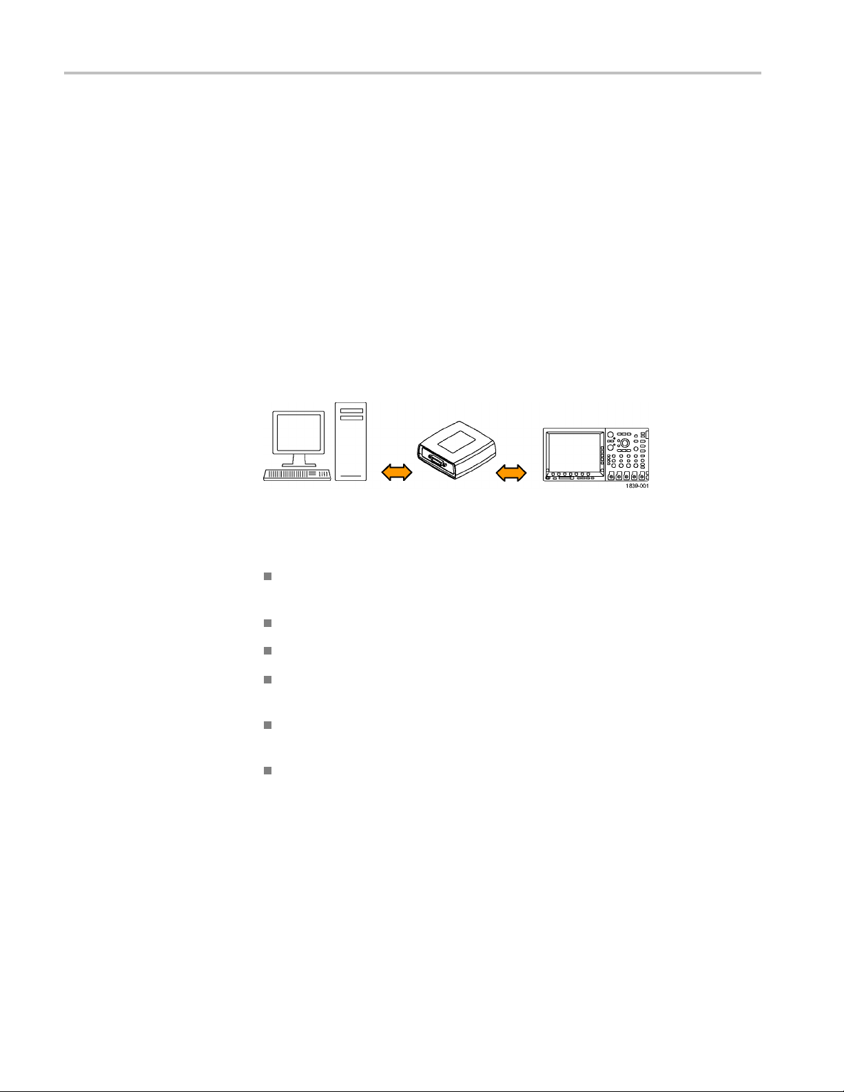
Connect your oscilloscope directly to a computer to let the PC analyze your data,
collect screen images, or to control the oscilloscope using a program of your own
creation. Three ways to connect your oscilloscope to a computer are through the
VISA drivers, the e*Scope Web-enabled tools, or via a socket server.
Using
VISA
VISA lets you use your MS-Windows computer to acquire data from your
oscilloscope for use in an analysis package that runs on your PC, such as
Microsoft Excel, National Instruments LabVIEW, Tektronix OpenChoice Desktop
ware, or your own custom software. You can use a common communications
soft
connection, such as USB, Ethernet, or GPIB, to connect the computer to the
oscilloscope.
To set up VISA communications between your oscilloscope and a computer:
MSO3000 and DPO3000 Series Programmer Manual 1-5

Getting Started
1. Load the VISA dr
as OpenChoice Desktop. You will find the drivers and OpenChoice Desktop
software on the appropriate CD that comes with your oscilloscope or at the
Tektronix software finder Web page (www.tektronix.com).
2. Connect the oscilloscope to your computer with the appropriate USB or
Ethernet cable. You will find the drivers and OpenChoice Desktop software
on the appropriate CD that comes with your oscilloscope or at the Tektronix
software fi nder Web page (www.tektronix.com/downloads).
3. On the front panel, push Utility.
4. Push Utility Page on the lower menu.
5. Turn multipurpose knob a and select I/O.
6. If you are using USB, the system sets itself up automatically for you, if USB is
enabled. Check USB on the lower menu to be sure that USB is enabled. If it is
not enabled, push USB. Then push Connect to Computer on the side menu.
7. To use Ethernet, push Ethernet Network Settings on the lower menu. Use
the side menu buttons to adjust your network settings, as needed. For more
information, see the e*Scope setup information below.
8. If you want to change socket server parameters, push Socket Server and enter
new values through the resulting side menu.
ivers on your computer. Also, load your application, such
Quick Tips
Using e*Scope
9. If you are using GPIB, push GPIB. Enter the GPIB address on the side menu,
using multipurpose knob a.
10. Run your application software on your computer.
Your oscilloscope shipped with a CD containing a variety of Windows-based
software tools for efficient connectivity between your oscilloscope and your
computer. These include toolbars that speed connectivity with Microsoft
Excel a nd Word. There are also two standalone acquisition programs called
NI LabVIEW SignalExpress™, Tektronix Edition and Tektronix OpenChoice
esktop.
D
The rear-panel USB 2.0 device port is the correct USB port for computer
connectivity. Use the rear- and front-panel USB 2.0 host ports to connect
your oscilloscope to USB flash drives, printers and keyboards. Use the USB
Device port to connect your oscilloscope to a PC or a PictBridge printer.
With e*Scope, you can use a web browser on your computer to send and receive
commands using any connected MSO/DPO3000 Series oscilloscope. To set up
e*Scope communications between your oscilloscope and a Web browser running
onaremotecomputer:
1-6 MSO3000 and DPO3000 Series Programmer Manual

Getting Started
1. Connect the osc
Ethernet cable.
2. On the front panel, push Utility.
3. Push Utility P age on the lower menu.
4. Turn multipurpose knob a and select I/O.
5. Push Ethernet Network Settings.
6. Push Change Instrument Settings to display and change the instrument
setup on your oscilloscope. Optional: enter an Instrument IP address if
you’d like to manually configure it.
7. Push Test Connection to check if your oscilloscope can find an attached
network.
8. Start y our browser on your remote computer. In the browser address line,
enter the host name, a dot, and the domain name together. Alternatively, just
enter the IP address of the instrument. Either way, you should then see the
e*Scope page on your Web browser on your computer screen.
9. ClickontheDatatabonthee*Scopepage.UnderTalk/Listen, you may enter
and send commands to the connected oscilloscope.
illoscope to your computer network with an appropriate
Using a Socket Server
ket server provides two-way communication over an Internet Protocol-based
Asoc
computer network. You can use your oscilloscope’s socket server feature to let
your oscilloscope talk to a remote-terminal device or computer.
To set up and use a socket server between your oscilloscope and a remote terminal
or computer:
1. Connect the oscilloscope to your computer network with an appropriate
Ethernet cable.
2. Push Utility.
3. Push Utility Page.
4. Turn multipurpose knob a and select I/O.
5. Push Socket Server.
6. On the resulting Socket Server side menu, push the top entry to highlight
Enabled.
7. Choose whether the protocol should be None or Term i na l . A communication
session run by a human at a keyboard typically uses a terminal protocol.
An automated session might h andle its own communications without using
such a protocol.
8. If required, change the port number by rotating multipurpose knob a.
9. If required, press OK to set the new port number.
MSO3000 and DPO3000 Series Programmer Manual 1-7

Getting Started
10. After setting u
p the socket server parameters, you can now have the computer
talk to the oscilloscope. If you are running an MS Windows PC, you could
run its default client with its command-like interface. One way to do this is
by typing “
Telnet ” in the Run window. The Telnet window will open on
the PC.
NOTE. On MS Windows 7, you must first enable Telnet for it to work.
11. Start a terminal session between your computer and your oscilloscope by
typing in an open command with the oscilloscope's LAN a ddress and port #.
You can obtain the LAN address by pushing the Ethernet Network
Settings bottom menu item and then Change Instrument Settings on the
ng side menu.
resulti
You can obtain the port number by pushing the Socket Server bottom
menu ite
For example, if the oscilloscope IP address was
port # w
m and viewing the Current Port side menu item.
123.45.67.89 and the
as the default of
4000, you could open a session by writing into
the MS Windows Telnet screen:
o 123.
45.67.89 4000
12. You can now type in a standard query, as found in the programmer manual,
as
such
*idn?
The Telnet session window will respond by displaying a character string
cribing your instrument.
des
You can type in more queries and view more results on this Telnet session
ndow. You can find the syntax for relevant queries and related status
wi
codes in other sections of this manual.
NOTE. Do not use the computer’s backspace key during an MS Windows' Telnet
session with the oscilloscope.
Socket Server Terminal Protocol Mode Commands. Following are Tektronix
Instrument Control Terminal Session Control commands:
!t <timeout> : set the response timeout in milliseconds.
!d : send device clear to the instrument.
!r : read response from instrument.
!h : print this usage info.
1-8 MSO3000 and DPO3000 Series Programmer Manual

Getting Started
Documentation
NOTE. Commands
read automatically.
The followin
site at www.tektronix.com/downloads:
MSO3000 and
and operating the oscilloscope.
Getting St
from your oscilloscope into any one of several available analysis tools.
MSO3000 a
and a performance verification procedure.
TekV ISA
implementation of the VISA Application Programming Interface (API). TekVISA
is industry-compliant software for writing interoperable oscilloscope drivers in a
variety of Application Development Environments (ADEs).
arted with OpenChoice ™ Solutions Manual. Options for getting data
nd DPO3000 Series Technical Reference. Oscilloscope specifications
Programmer Manual. Description of TekVISA, the Tektronix
containing a ? are treated as queries, and the responses are
g documents are available for download on the Manuals Finder Web
DPO3000SeriesUserManual. Information about installing
MSO3000 and DPO3000 Series Programmer Manual 1-9

Getting Started
1-10 MSO3000 and DPO3000 Series Programmer Manual

Command Syntax
You can control the operations and functions of the oscilloscope through the
Ethernet port or the USB 2.0 device port using commands and queries. The
related topi
The topics also describe the conventions that the oscilloscope uses to process
them. See the Command Groups topic in the table of contents for a listing o f the
commands by command group, or use the index to locate a specific command.
cs listed below describe the syntax of these commands and queries.
Backus-Naur Form
Notation
This documentation describes the commands and queries using Backus-Naur
Form (BNF) notation. Refer to the following table for the symbols that are used.
Table 2-1: Symbols for Backus-Naur Form
Symbol Meaning
<>
=
| Exclusive OR
{ } Group; one element is required
[]
.. .
( ) Comment
Command and Query Structure
mmands consist of set commands and query commands (usually called
Co
commands and queries). Commands modify oscilloscope settings or tell the
oscilloscope to perform a specific action. Queries cause the oscilloscope to return
data and status information.
Defined element
Is defined as
Optional; can be omitted
Previous element(s) may be repeated
Most commands have both a set form and a query form. The query form of the
command differs from the set form by its question mark at the end. For example,
the set command
commands have both a set and a query form. Some commands have set only and
some have query only.
Messages
MSO3000 and DPO3000 Series Programmer Manual 2-1
A command message is a command or query name followed by any information
the oscilloscope needs to execute the command or query. Command messages
may c ontain five element type s, defined in the following table.
ACQuire:MODe has a query form ACQuire:MODe?.Notall

Command Syntax
Commands
Table 2-2: Comm
Symbol Meaning
<Header>
<Mnemonic>
<Argument
<Comma> A single c
<Space>
Comman
>
ds cause the oscilloscope to perform a specific function or change one of
and Message Elements
This is the basic command name. If the header ends with a question
mark, the command is a query. The header may begin with a colon
(:) characte
the beginning colon is required. Never use the beginning colon with
command headers beginning with a star (*).
This is a header subfunction. Some command headers have only one
mnemonic. I
character always separates them from each other.
This is a qu
Some commands have no arguments while others have multiple
arguments. A <space> separates arguments from the header. A
<comma> se
commands. Optionally, there may be white space characters before
and after the comma.
A white space character is used between a command header and the
related argument. Optionally, a white space may consist of multiple
white sp
r. If the command is concatenated with other commands,
f a command header has multiple mnemonics, a colon (:)
antity, quality, restriction, or limit associated with the header.
parates arguments from each other.
omma is used between arguments of multiple-argument
ace characters.
the settings. Commands have the structure:
eader>[<Space><Argument>[<Comma> <Argument >]...]
[:]<H
A command header consists of one or more mnemonics arranged in a hierarchical
ee structure. The first mnemonic is the base or root of the tree and each
or tr
subsequent mnemonic is a level or branch off the previous one. Commands at a
higher level in the tree may affect those at a lower level. The leading colon (:)
always returns you to the base of the command tree.
2-2 MSO3000 and DPO3000 Series Programmer Manual

Command Syntax
Queries
Headers
Queries cause t
have the structure:
[:]<Header>
[:]<Header>[<Space><Argument> [<Comma><Argu ment>]...]
You can specify a query command at any level within the command tree unless
otherwise noted. These branch queries return information about all the mnemonics
below the specified branch or level.
Use the HEADer command to control whether the oscilloscope returns headers as
part of the query response. If header is on, the query response returns command
headers, then formats itself as a valid set command. When header is off, the
response includes only the values. This may make it easier to parse and extract the
information from the response. The table below shows the difference in responses.
Table 2-3: Comparison of Header Off and Header On R esponses
Query Header Off Header On
TIME?
ACQuire:NUMAVg?
he oscilloscope to return status or setting information. Queries
14:30:00 :TIME “14:30:00”
100
:ACQUIRE:NUMAVG 100
Clearing the oscilloscope
You can clear the Output Queue and reset the oscilloscope to accept a new
command or query by using the selected Device Clear (DCL) function.
Command Entry
The following rules apply when entering commands:
You can enter commands in upper or lower case.
You can precede any command with white space characters. White space
characters include any combination of the ASCII control characters 00 through
09 and 0B through 20 hexadecimal (0 through 9 and 11 through 32 decimal).
The oscilloscope ignores commands consisting of any combination of white
space characters and line feeds.
MSO3000 and DPO3000 Series Programmer Manual 2-3

Command Syntax
Abbreviating
Concatenating
You can abbrevi
ate many oscilloscope commands. Each command in this
documentation shows the minimum acceptable abbreviations in capitals. For
example, you can enter the command ACQuire:NUMAvg simply as ACQ:NUMA
or acq:numa.
Abbreviation rules may change over time as new oscilloscope models are
introduced. Thus, for the most robust code, use the full spelling.
If you use the HEADer command to have command headers included as part
of query responses, you can further control whether the returned headers are
abbreviated or are full-length with the VERBose command.
You can concatenate any combination of set commands and queries using a
semicolon (;). The oscilloscope executes concatenated commands in the order
received.
When concatenating commands and queries, you must follow these rules:
1. Separate completely different headers by a semicolon and by the beginning
colon on all commands except the first one. For example, the commands
TRIGger:MODe NORMal and ACQ uire:NUMAVg 8, can be concatenated
into the following single command:
TRIGger:MODe NORMal;:ACQuire:NUMAVg 8
2. If concatenated commands have headers that differ by only the last mnemonic,
you can abbreviate the second command and eliminate the beginning colon.
For example, you can concatenate the commands
ACQuire:MODe ENVelope
and ACQuire:NUMAVg 8 into a single command:
ACQuire:MODe ENVelope; NUMAVg 8
The longer version works equally well:
ACQuire:MODe ENVelope;:ACQuire:NUMAVg 8
3. Never precede a star (*) command with a colon:
ACQuire:STATE 1;*OPC
Any commands that follow will be processed as if the star command was
not there so the commands,
ACQuire:MODe ENVel
ope;*OPC;NUMAVg 8
will set the acquisition mode to envelope and set the number of acquisitions
for averaging to 8.
4. When you concatenate queries, the responses to all the queries are
concatenated into a single response message. For example, if the display
graticule is set to Full and the display style is set to dotsonly, the concatenated
query
DISplay:GRAticule?;STYle:DOTsonly? will return the following.
Iftheheaderison:
DISPLAY:GRATICULE FULL;:DISPLAY:STYLE:DOT SONLY 1
2-4 MSO3000 and DPO3000 Series Programmer Manual

Command Syntax
If the header is
FULL;1
off:
5. Set commands and queries may be concatenated in the same message. For
example,
ACQuire:MODe SAMple;NUMAVg?;STATE?
is a valid message that sets the acquisition mode to sample. The message then
queries the number of acquisitions for averaging and the acquisition state.
Concatenated comma nds and queries are executed in the order received.
Here are some invalid concatenations:
DISPlay:STYle:NORMal;ACQuire:NUMAVg 8 (no colon before ACQuire)
DISPlay:GRAticule FULL;:DOTSONLY OFF (extra colon before
DOTSonly. You could use DISPlay:DOTsonly OFF instead)
DISPlay:GRAticule FULL;:*TRG (colon before a star (*) command)
MATH:HORizontal:SCAle 1.0e-1;HORizontal:P OSition 5.0el
(levels of the mnemonics are different; either remove the second use of
HORizontal: or place :MATH in front of HORizontal:POSition)
Terminating
This documentation uses <EOM> (End of Message) to represent a message
terminator.
Table 2-4: End of Message Terminator
Symbol Meaning
<EOM>
Th
concurrently with the last data byte). The last data byte may be an ASCII line
feed (LF) character.
This oscilloscope does not support ASCII LF only message termination. The
oscilloscope always terminates outgoing messages with LF and EOI.
Constructed Mnemonics
Some header mnemonics specify one of a range of mnemonics. For example, a
channel mnemonic can be CH1, CH2, CH3, or CH4. You use these mnemonics
in the command just as you do any other mnemonic. For example, there is a
CH1:POSition command, and there is also a CH2:POSition command. In the
command descriptions, this list of choices is abbreviated as CH<x>.
Message terminator
e end-of-message terminator must be the END message (EOI asserte d
MSO3000 and DPO3000 Series Programmer Manual 2-5

Command Syntax
Math Spe
Cursor Position
Mnemonics
cifier Mnemonics
When cursors ar
e displayed, commands may specify which cursor of the pair to
use.
Table 2-5: Channel Mnemonics
Symbol Meaning
CH<x> A channel specifier; <x> is 1 through 4.
Table 2-6: Cursor Mnemonics
Symbol Meaning
CURSOR<x>
POSITION<x>
HPOS<x>
A cursor selector; <x> is either 1 or 2.
A cursor selector; <x> is either 1 or 2.
A cursor selector; <x> is either 1 or 2.
Commands can specify the mathematical waveform to use as a mnemonic in
the header.
Table 2-7: Math Specifier Mnemonics
Symbol Meaning
Math<x>
A math waveform specifier; <x> is 1.
Measurement Specifier
Mnemonics
hannel Mnemonics
C
Reference Waveform
Mnemonics
Commands can specify which measurement to set or query as a mnemonic in the
header. Up to four automated measurements may be displayed.
Table 2-8: Measurement Specifier Mnemonics
Symbol Meaning
MEAS<x> A measurement specifier; <x> is 1 through 4.
Commands specify the channel to use as a mnemonic in the header.
Commands can specify the reference waveform to use as a mnemonic in the
header.
Table 2-9: Reference Waveform Mnemonics
Symbol Meaning
REF<x>
A reference waveform specifier; <x> is 1, 2, 3, or 4 for 4-channel
oscilloscopes and 1 or 2 for 2-channel oscilloscopes.
2-6 MSO3000 and DPO3000 Series Programmer Manual

Argument Types
Command Syntax
Commands use arguments such as enumeration, numeric, quoted string and block.
Each of these arguments are listed in detail below.
Enumeration
Numeric
Enter these arguments as unquoted text words. Like key words, enumeration
arguments follow the same convention where the portion indicated in uppercase is
required and that in lowercase is optional.
For example:
Many osci
SAVe:WAVEform:FILEFormat INTERNal
lloscope commands require numeric arguments. The syntax shows
the format that the oscilloscope returns in response to a query. This is also the
preferred format when sending the command to the oscilloscope though any of
the formats will be accepted. This documentation represents these arguments as
described below.
Table 2-10: Numeric Arguments
Symbol Meaning
<NR1>
<NR2> Floating point value without an exponent
<NR3> Floating point value with an exponent
<bin>
Signed integer value
Digital data in binary format
Most numeric arguments will be automatically forced to a valid setting, by either
rounding or truncating, when an invalid number is input, unless otherwise noted
the command description.
in
Quoted String
Some commands accept or return data in the form of a quoted string, which is
simply a group of ASCII characters enclosed by a single quote (') or double quote
"). The following is an example of a quoted string:
(
string"
. This documentation represents these arguments as follows:
"This is a quoted
Table 2-11: Quoted String Argument
Symbol Meaning
<QString> Quoted string of ASCII text
MSO3000 and DPO3000 Series Programmer Manual 2-7

Command Syntax
A quoted string
can include any character defined in the 7-bit ASCII character
set. Follow these rules when you use quoted strings:
1. Use the same ty
example:
2. You can mix q
previous rule. For example:
3. You c an i nc l
example:
4. Strings ca
pe of quote character to open and close the string. For
"this is a valid string".
uotation marks within a string as long as you follow the
"this is an 'acceptabl e' string ".
ude a quote character within a string by repeating the quote. For
"here is a "" mark".
n have upper or lower case characters.
5. If you use a GPIB network, you cannot terminate a quoted string with the
END messa
ge before the closing delimiter.
6. A carriage return or line feed embedded in a quoted string does not terminate
the s tri
ng. The return is treated as another character in the string.
7. The maximum length of a quoted string returned from a query is 1000
ters.
charac
Here are some invalid strings:
"Invalid string argument' (quotes are not of the same type)
Block
"test<EOI>" (termination character is embedded in the string)
Several oscilloscope commands use a block argument form, as defined in the
table below.
Table 2 -12: Block Argument
Symbol Meaning
<NZDig>
<Dig>
<DChar> A character with the hexadecimal equivalent of 00 through FF (0
<Block>
A nonzero digit character i n the range of 1–9
A digit character, in the range of 0–9
through 255 decimal)
A block of data bytes defined as: <Block> ::=
{#<NZDig><Dig>[<Dig>...][<DChar>...] |#0[<DChar>...]<terminator>}
<NZDig> specifies the number of <Dig> elements that follow. Taken together,
the <NZDig> and <Dig> elements form a decimal integer that specifies how
many <DChar> elements follow.
2-8 MSO3000 and DPO3000 Series Programmer Manual

Command Syntax
MSO3000 and DPO3000 Series Programmer Manual 2-9

Command Syntax
2-10 MSO3000 and DPO3000 Series Programmer Manual

Command Groups
This manual lists the MSO/DPO3000 Series IEEE488.2 commands in two ways.
First, it presents them by functional groups. Then, it lists them alphabetically. The
functional g
command. (See page 2-93, Commands Listed in Alphabetical Order.)
Acquisition Command Group
Use the commands in the Acquisition Command Group to set up the modes and
functions that control how the oscilloscope acquires signals input to the channels,
and processes them into waveforms.
Using the commands in this group, you can do the following:
Start and stop acquisitions.
roup list starts below. The alphabetical list provides detail on each
Control
whether each waveform is simply acquired, averaged, or enveloped
over successive acquisitions of that waveform.
Set the
controls or conditions that start and stop acquisitions.
Control acquisition of channel waveforms.
Set acquisition parameters.
Table 2-13: Acquisition Commands
Command Description
ACQuire?
ACQuire:MAGnivu Sets or returns the MagniVu feature
ACQuire:MAXSamplerate?
ACQuire:MODe Sets or returns the acquisition mode
ACQuire:NUMACq? Returns the number of acquisitions that have
ACQuire:NUMAVg Sets or returns the number of acquisitions for
ACQuire:NUMEnv This command controls the number of
ACQuire:STATE Starts or stops the acquisition system
ACQuire:STOPAfter Sets or returns whether the acquisition is
Returns the acquisition parameters
Returns the maximum real-time sample rate
occurred
an averaged waveform
envelopes (when acquisition mode has been
set to ENVelope using ACQuire:MODe). The
number of envelopes can be set from 1 to
2000 in increments of 1, or to INFInite.
continuous or single sequence
MSO3000 and DPO3000 Series Programmer Manual 2-11

Command Groups
Alias Command
Group
Use the Alias commands to define new commands as a sequence of standard
commands. You may find this useful when repeatedly using the same commands
to perform ce
rtain tasks like setting up measurements.
Aliases are similar to macros but do not include the capability to substitute
parameters
into alias bodies. The alias mechanism obeys the following rules:
The alias name must consist of a valid IEEE488.2 message unit, which may
not appear
in a message preceded by a colon, comma, or a command or query
program header.
The a lias
name may not appear in a message followed by a colon, comma,
or question mark.
An alias
name must be distinct from any keyword or keyword short form.
An alias name cannot be redefined without first b eing deleted using one of
as deletion functions.
the ali
Alias names do not appear in response messages.
2-14: Alias Commands
Table
Command Description
s
ALIa
ALIas:CATalog? Returns a list of the currently defined alias
ALIas:DEFine
ALIas:DELEte
ALIas:DELEte:ALL Deletes all existing aliases
ALIas:DELEte[:NAMe]
ALIas[:STATE] Sets or returns the alias state
Sets or returns the alias state
labels
Assigns a sequence of program messages
n alias label
to a
moves a specified alias
Re
Removes a specified alias
2-12 MSO3000 and DPO3000 Series Programmer Manual

Command Groups
Bus Command Gr
oup
Use the Bus commands when working with serial or parallel bus measurements.
Install the DPO3EMBD application module when working with I2CorSPI
bus signals.
Install the DPO3AUTO module when working with CAN or LIN bus signals.
Install the DPO3COMP module when working with RS-232, RS-422,
RS-485, and UART bus signals.
Install the DPO3AUDIO module when working with I2S, Left Justified (LJ),
Right Justified (RJ), and TDM bus signals.
Install the DPO3AERO module when working with MIL-STD-1553 bus
signals.
Install the DPO3FLEX module when working with FlexRay bus signals.
NOTE. Parallel bus trigger and analysis functionality is included standard with
the MSO Series.
NOTE.
The Search Command Group and the Trigger Command Group also
contain bus-related commands.
Table2-15:BusCommands
Commands Description
BUS Returns the parameters for each bus
BUS:B<x>:AUDio:BITDelay Sets or returns the number of delay bits for
the AUDIO bus
BUS:B<x>:AUDio:BITOrder Sets or returns the bit order for the AUDIO
bus
BUS:B<x>:AUDio:CHANnel:SIZe Sets or returns the number of bits per
channel for the AUDIO bus
BUS:B<x>:AUDio:CLOCk:POLarity Sets or returns the clock polarity for the
AUDIO bus
BUS:B<x>:AUDio:CLOCk:SOUrce Sets or returns the clock source waveform
for the AUDIO bus
BUS:B<x>:AUDio:DATa:POLarity Sets or returns the data polarity for the
AUDIO bus
BUS:B<x>:AUDio:DATa:SIZe Sets or returns the number of bits per word
for the AUDIO bus
BUS:B<x>:AUDio:DATa:SOUrce Sets or returns the data source waveform for
the AUDIO bus
MSO3000 and DPO3000 Series Programmer Manual 2-13

Command Groups
Table2-15: BusCommands(cont.)
Commands Description
BUS:B<x>:AUDio:DISplay:FORMat Sets or returns the display format for the
AUDIO bus
BUS:B<x>:AUDio:FRAME:SIZe Sets or returns the number of channels in
each frame for the AUDIO bus
BUS:B<x>:AUDio:FRAMESync:POLarity Sets or returns the frame sync polarity for
the AUDIO bus
BUS:B<x>:AUDio:FRAMESync:SOUrce Sets or returns the frame sync source
waveform for the AUDIO bus
BUS:B<x>:AUDio:TYPe Sets or returns the audio format (type) for
the AUDIO bus
BUS:B<x>:AUDio:WORDSel:POLarity Sets or returns the word select polarity for
the AUDIO bus
BUS:B<x>:AUDio:WORDSel:SOUrce Sets or returns the word s elect source
waveform for the AUDIO bus
BUS:B<x>:CAN:BITRate Sets or returns the bit rate for the CAN bus
BUS:B<x>:CAN:PRObe Sets or returns the probing method used to
probe the C AN bus
BUS:B<x>:CAN:SAMPLEpoint Sets or returns the sample point (in %) to
sample during each bit period
BUS:B<x>:CAN:SOUrce Sets or returns the CAN data source
BUS:B<x>:DISplay:FORMAt Sets the display format for the numerical
information in the specified bus waveform
BUS:B<x>:DISplay:TYPe Sets the display type for the specified bus
BUS:B<x>:FLEXray:BITRate This command specifies the bit rate for
FlexRay
BUS:B<x>:FLEXray:CHannel This command specifies the FlexRay ID
format
BUS:B<x>:FLEXray:SIGnal Specifies which FlexRay standard to use:
BDIFFBP, BM or TXRX.
BUS:B<x>:FLEXray:SOUrce This command specifies the FlexRay data
source
BUS:B<x>:I2C:ADDRess:RWINClude Sets and returns whether the read/write bit is
included in the address
BUS:B<x>:I2C{:CLOCK|:SCLK}:SOUrce Sets or returns the I2C SCLK source
BUS:B<x>:I2C{:DATA|:SD ATA}:SOUrce Sets or returns the I2C SDATA source
BUS:B<x>:LABel Sets or returns the waveform label for the
specified bus
BUS:B<x>:LIN:BITRate Sets or returns the bit rate for LIN
BUS:B<x>:LIN:IDFORmat Sets or returns the LIN ID format
BUS:B<x>:LIN:POLARity Sets or returns the LIN polarity
2-14 MSO3000 and DPO3000 Series Programmer Manual

Command Groups
Table 2-15: Bus Commands (cont.)
Commands Description
BUS:B<x>:LIN:SAMPLEpoint Sets or returns the sample point (in %) at
which to sample during each bit period
BUS:B<x>:LIN:SOUrce Sets or returns the LIN data source
BUS:B<x>:LIN:STANDard Sets or returns the LIN standard
BUS:B<x>:MIL1553B:POLarity This command sets the MIL-STD-1553 bus
polarity to normal or inverted.
BUS:B<x>:MIL1553B:RESPonsetime:
MAXimum
BUS:B<x>:MIL1553B:RESPonsetime:
MINimum
BUS:B<x>:MIL1553B:SOUrce This command specifies the M IL-STD-1553
BUS:B<x>:PARallel:BIT<x>:SOUrce Sets or returns the parallel bit source for the
BUS:B<x>:PARallel:CLOCK:EDGE Sets or returns the parallel clock edge for the
BUS:B<x>:PARallel:CLOCK:ISCLOCKed Sets or returns the parallel bus clock function
BUS:B<x>:PARallel:CLOCK:SOUrce Sets or returns the parallel clock source for
BUS:B<x>:PARallel:WIDth Sets or returns the width of the parallel bus
BUS:B<x>:POSition Sets or returns the position of the specified
BUS:B<x>:RS232C:BITRate Sets or returns the RS-232 bit rate for the
BUS:B<x>:RS232C:DATABits Sets or returns the number of bits for the
BUS:B<x>:RS232C:DELIMiter Sets or returns the R S-232 delimiting value
BUS:B<x>:RS232C:DISplaymode Sets or returns the display mode for the
BUS:B<x>:RS232C:PARity Sets or returns the parity for RS-232 data
BUS:B<x>:RS232C:POLarity Sets or returns the RS-232C polarity for the
BUS:B<x>:RS232C:RX:SOUrce Sets or returns the RS-232 RX source
BUS:B<x>:RS232C:TX:SOUrce Sets or returns the RS-232 TX Source
BUS:B<x>:SPI{:CLOCK|:SCLK}:POLARity Sets or returns the SPI SCLK polarity
BUS:B<x>:SPI{:CLOCK|:SCLK}:SOUrce Sets or returns the SPI SCLK source
BUS:B<x>:SPI:DATA{:IN|:MISO}:POLARity Sets or returns the SPI MISO polarity
BUS:B<x>:SPI:DATA{:IN|:MISO}:SOUrce Sets or returns the SPI MISO source
This command specifies the maximum
response time to a valid command issued.
This command specifies the minimum
response time to a valid command issued.
bus source for differential input.
specified bus
specified bus
for the specified bus
the specified bus
bus waveform
specified bus
data frame
for a packet on the specified bus
specified bus display and event table
specified bus
MSO3000 and DPO3000 Series Programmer Manual 2-15

Command Groups
Table2-15: BusCommands(cont.)
Commands Description
BUS:B<x>:SPI:DATA{:OUT|:MOSI}:
POLARity
BUS:B<x>:SPI:DATA{:OUT|:MOSI}:SOUrce Sets or returns the SPI MOSI source
BUS:B<x>:SPI{:SELect|:SS}:POLARity Sets or returns the SPI SS polarity
BUS:B<x>:SPI{:SELect|:SS}:SOUrce Sets or returns the SPI SS source
BUS:B<x>SPI:FRAMing Sets or returns the type of SPI framing
BUS:B<x>:STATE Turns the specified bus on and off
BUS:B<x>:TYPE Sets or returns the specified bus type
BUS:LOWerthreshold:CH<x> Sets or returns the lower threshold for each
BUS:THReshold:D<x> Sets or returns the threshold for a digital
BUS:UPPerthreshold:CH<x> Sets or returns the upper threshold for each
Sets or returns the SPI MOSI polarity
channel
channel
channel
2-16 MSO3000 and DPO3000 Series Programmer Manual

Command Groups
Calibration a
nd Diagnostic Command Group
The Calibration and Diagnostic commands provide information about the current
state of oscilloscope calibration. They also initiate internal signal path calibration
(SPC) or exec
calibration are not described in this manual. They are described in the Service
manual, located on the DPO3000 Documentation CD-ROM in PDF format. You
can also order a printed copy.
Table 2-16: Calibration and Diagnostic Commands
Command
*CAL? Instruct
CALibrate:FACtory:STATus? Returns the factory calibration status value
ate:INTERNal
CALibr
rate:INTERNal:STARt
CALib
rate:INTERNal:STATus?
CALib
CALibrate:RESults? Returns the status of all calibration
ibrate:RESults:FACtory?
CAL
CALibrate:RESults:SPC? Returns the results o f the last S P C operation
DIAg:LOOP:OPTion Sets the self-test loop option
DIAg:LOOP:OPTion:NTIMes Sets the self-test loop option to run N times
DIAg:LOOP:STOP Stops the self-test at the end of the current
DIAg:RESUlt:FLAg? Returns the pass/fail status from the last
DIAg:RESUlt:LOG? Returns the internal results log from the last
DIAg:SELect:<function> Selects one of the available s elf-test areas
DIAg:STATE Sets the oscilloscope operating state
DIAg:SELect Sets the type of diagnostics grouping
ute diagnostic tests. Commands that are specifictofactory
Description
s the oscilloscope to perform
self-calibration and returns the oscilloscope
self calibration status
saved in
Starts
Start
Retur
signal path calibration
subsystems without performing an SPC
oper
Ret
calibration
loop
self-test sequence execution
self-test sequence execution
nonvolatile memory
a signal path compensation
s the internal signal path calibration
ns the current status of the internal
ation
urns the status of internal and factory
Configuration Command Group
Use the queries in the Configuration Command Group to determine whether a
particular feature is present.
MSO3000 and DPO3000 Series Programmer Manual 2-17

Command Groups
Table 2-17: Con
Command
CONFIGuration:ADVMATH?
CONFIGuration:ANALOg:GNDCPLG?
CONFIGurat
CONFIGura
MAXSAMPLERate?
CONFIGuration:ANALOg:NUMCHANnels? This query returns the number of analog
CONFIGuration:ANALOg:RECLENS?
CONFIGu
CONFIGuration:APPLications:LIMITMask?
CONFIGuration:APPLications:POWer?
CONF
CONFIGuration:BUSWAVEFORMS:AUDIO?
CONFIGuration:BUSWAVEFORMS:CAN?
CO
ETHERNET?
CONFIGuration:BUSWAVEFORMS:
FLEXRAY?
ration:ANALOg:VERTINVert?
IGuration:AUXIN?
NFIGuration:BUSWAVEFORMS:
figuration Commands
ion:ANALOg:MAXBANDWidth?
tion:ANALOg:
Description
This query ret
indicate whether the advanced math feature
is present.
This query returns a boolean value to
indicate whether the ground coupling feature
for analog ch
This query returns the maximum bandwidth
for analog c
This query returns the maximum sample rate
for analog
channels.
This query returns a comma-separated list
of supported record lengths for the analog
channels
This query returns a boolean value to
indicat
analog channels is present.
This qu
indicate whether the optional mask/limit
test application feature is present. As the
MSO/DP
not support this feature, this query always
returns 0.
This query returns a boolean value to indicate
whether the optional power application
re is present.
featu
This query returns a boolean value to
cate whether the instrument has an
indi
auxiliary input.
query returns a boolean value to
This
indicate whether the optional audio bus
triggering and analysis feature is present.
This query returns a boolean value to indicate
whether the optional CAN bus triggering and
lysis feature is present.
ana
This query returns a boolean value to
dicate whether the optional Ethernet
in
triggering and analysis feature is present. As
the MSO/DPO3000 Series oscilloscopes do
t support this feature, this query always
no
returns 0.
his query returns a boolean value to
T
indicate whether the optional FlexRay bus
triggering and analysis feature is present.
urns a boolean value to
annels is present.
hannels.
channels.
.
e whether the vertical invert feature for
ery returns a boolean value to
O3000 Series oscilloscopes do
2-18 MSO3000 and DPO3000 Series Programmer Manual

Tabl e 2-17: Configuration Commands (cont.)
Command Groups
Command
CONFIGuration:BUSWAVEFORMS:I2C?
CONFIGuration:BUSWAVEFORMS:LIN?
CONFIGuration:BUSWAVEFORMS:
MIL1553B?
CONFIGuration:BUSWAVEFORMS:
NUMBUS?
CONFIGuration:BUSWAVEFORMS:
PARALLEL?
CONFIGuration:BUSWAVEFORMS:RS232?
CONFIGuration:BUSWAVEFORMS:SPI?
CONFIGuration:BUSWAVEFORMS:USB?
CONFIGuration:BUSWAVEFORMS:USB:
HS?
CONFIGuration:DIGITAl:MAGNIVU?
CONFIGuration:DIGITAl:
MAXSAMPLERate?
CONFIGuration:DIGITAl:NUMCHANnels? This query returns the number of digital
CONFIGuration:EXTVIDEO?
Description
This query returns a boolean value to indicate
whether the optional I
analysis feature is present.
This query returns a boolean value to indicate
whether the optional LIN bus triggering and
analysis feature is present.
This query returns a boolean value to indicate
whether the optional MIL-STD-1553 bus
triggering and analysis feature is present.
This query returns the number of bus
waveforms.
This query returns a boolean value to
indicate whether the parallel bus triggering
and analysis feature is present.
This query returns a boolean value to
indicate whether the optional RS232 bus
triggering and analysis feature is present.
This query returns a boolean value to indicate
whether the optional SPI bus triggering and
analysis feature is present.
This query returns a boolean value to indicate
whether the USB bus triggering and analysis
feature is present. As the MSO/DPO3000
Series oscilloscopes do not support this
feature, this query always returns 0.
This query returns a boolean value to
indicate whether the high-speed USB bus
triggering and analysis feature is present. As
the MSO/DPO3000 Series oscilloscopes do
not support this feature, this query always
returns 0.
This query returns a boolean value to
indicate whether the instrument supports the
MagniVu feature for digital channels. If there
are no digital channels, the value returned
is 0.
This query returns the maximum sample
rate for digital channels, in samples per
second. If there are no digital channels, the
value returned is 0.
channels.
This query returns a boolean value to
indicate whether the optional extended video
trigger features are present.
2
C bus triggering and
MSO3000 and DPO3000 Series Programmer Manual 2-19

Command Groups
Table 2-17: Configuration Commands (cont.)
Command
CONFIGuration:HISTOGRAM?
CONFIGuration:NETWORKDRIVES?
CONFIGuration:NUMMEAS? This query returns the number of periodic
CONFIGuration:REFS:NUMREFS? This query returns the number of reference
CONFIGuration:RF:ADVTRIG?
CONFIGuration:RF:MAXBANDWidth?
CONFIGuration:RF:NUMCHANnels? This query returns the number of RF
CONFIGuration:ROSC?
Description
This query returns a boolean value to indicate
whether the histogram feature is present. As
the MSO/DPO3000 Series oscilloscopes do
not support this feature, this query always
returns 0.
This query returns a boolean value to
indicate whether network drives are present.
As the MSO/DPO3000 Series oscilloscopes
do not support this feature, this query always
returns 0.
measurements.
waveforms.
This query returns a boolean value to
indicate whether the advanced RF trigger
feature is present. As the MSO/DPO3000
Series oscilloscopes do not support this
feature, this query always returns 0.
This query returns the maximum bandwidth,
in Hertz, for RF channels. As the
MSO/DPO3000 Series oscilloscopes do
not support this feature, this query always
returns 0.
channels present. As the MSO/DPO3000
Series oscilloscopes do not support this
feature, this query always returns 0.
This query returns a boolean value to
indicate whether the external reference
oscillator (ROSC) input is present.
2-20 MSO3000 and DPO3000 Series Programmer Manual

Command Groups
Cursor Comman
dGroup
Use the commands in the Cursor Command Group to control the cursor display
and readout. You can use these commands to control the setups for cursor 1 and
cursor 2, suc
You can also use the commands to select one of the following cursor functions:
Table 2-18: Cursor Commands
Command
CURSor?
CURSor:DDT? Returns the cursor deltaY/deltaT (dY/dT)
CURSor:FUNCtion Sets or returns the cursor type
CURSor:HBArs?
CURSor:HBArs:DELTa? Returns the hbars c ursors vertical difference
CURSor:HBArs:POSITION<x> Sets o r returns the hbar cursor<x> vertical
CURSor:HBArs:UNIts
CURSor:HBArs:USE Sets the horizontal bar cursor measurement
CURSor:MODe Sets or returns whether cursors move in
CURSor:VBArs? Sets or returns the position of vertical bar
CURSor:VBArs:ALTERNATE<x>? Returns the alternate readout for the
CURSor:VBArs:DELTa? Returns the horizontal difference between
CURSor:VBArs:HPOS<x>? Returns the vertical value of the specified
CURSor:VBArs:POSITION<x> Sets or returns the vbar cursor<x> horizontal
CURSor:VBArs:UNIts Sets or returns the horizontal units for vbar
CURSor:VBArs:USE Sets the vertical bar cursor measurement
h as cursor position.
Off. Turns off the display of all cursors.
Waveform Cursors. Consists of two cursors. Waveform cursors enable you to
conveniently measure waveform amplitude and time.
Screen Cursors. Consists of two pairs of independent horizontal and vertical
cursors. You can use these cursors to indicate an arbitrary position within
the waveform display area.
Description
Returns the cursor settings
readout
Returns the hbar cursor settings
position
Returns the hbar cursor units
scale, for use with ratio cursors
unison or separately
cursors
waveform (Vbar) cursors
vbar cursors
vertical bar tick
position
cursors
scale
MSO3000 and DPO3000 Series Programmer Manual 2-21

Command Groups
Table 2-18: Cursor Commands (cont.)
Command
CURSor:VBArs:VDELTa? Returns the vertical difference between the
CURSor:XY:POLar:RADIUS:DELta? Returns the difference between the cursors
CURSor:XY:POLar:RADIUS:POSITION<x>? Returns the polar radius of the specified
CURSor:XY:POLar:RADIUS:UNIts?
CURSor:XY:POLar:THETA:DELta?
CURSor:XY:POLar:THETA:POSITION<x>?
CURSor:XY:POLar:THETA:UNIts?
CURSor:XY:PRODUCT:DELta? Returns the difference between the cursors
CURSor:XY:PRODUCT:POSITION<x>? Returns the position of the X or Y cursor used
CURSor:XY:PRODUCT:UNIts?
CURSor:XY:RATIO:DELta? Returns the ratio of the difference between
CURSor:XY:RATIO:POSITION<x>? Returns the X or Y position for the specified
CURSor:XY:RATIO:UNIts? Returns the X and Y c ursor units for the ratio
CURSor:XY:READOUT Sets or returns the XY cursor readout
CURSor:XY:RECTangular:X:DELta?
CURSor:XY:RECTangular:X:POSITION<x> Sets or returns the cursor X rectangular
CURSor:XY:RECTangular:X:UNIts?
CURSor:XY:RECTangular:Y:DELta?
CURSor:XY:RECTangular:Y:POSITION<x>> Sets or returns the cursor Y rectangular
CURSor:XY:RECTangular:Y:UNIts?
Description
two vertical bar cursor ticks
X radius and the cursor Y radius
cursor
Returns the polar radius units
Returns the XY cursor polar coordinate delta
Returns the cursor X or cursor Y polar
coordinate
Returns the cursor polar coordinate units
X position and cursor Y position
to calculate the X × Y cursor measurement
Returns the XY cursor product units
the cursor X position and cursor Y position
cursor
measurement
selection
Returns the X delta value in rectangular
coordinates
coordinates
Returns the cursor X rectangular units
Returns the cursor Y delta value in
rectangular coordinates
coordinate
Returns the cursor Y rectangular units
Display Command Group
Use the commands in the Display Command Group to change the graticule style,
the display intensities, and to set the characteristics of the waveform display.
Also, use it to send messages to the display.
2-22 MSO3000 and DPO3000 Series Programmer Manual

Command Groups
NOTE. Your sett
ings globally affect all displayed waveforms.
Table 2-19: Display Commands
Command
DISplay?
DISplay:CLOCk Sets or returns the d isplay of the date/time
DISplay:DIGital:HEIght Sets or returns the number of available digital
DISplay:GRAticule This command specifies the type of graticule
DISplay:INTENSITy?
DISplay:INTENSITy:BACKLight Sets or returns the backlight intensity for the
DISplay:INTENSITy:GRAticule Sets or returns the graticule intensity for the
DISplay:INTENSITy:WAVEform Sets or returns the intensity of the waveforms
DISplay:PERSistence Sets or returns the display persistence
DISplay:STYle:DOTsonly Sets a dots-only display
DISplay:XY This command turns on or off the XY display
MESSage Sets or queries message box (screen
MESSage:BOX Sets or returns the coordinates of the
MESSage:CLEAR Clears the contents of the message box
MESSage:SHOW Sets or returns the contents of the message
MESSage:STATE Controls the display of the message box
Description
Returns the current display settings
stamp
waveform position slots
the oscilloscope displays.
Returns all the display intensity settings
display
display
setting
mode.
annotation) parameters
message box
box
Ethernet Command Group
Use the commands in the Ethernet Command Group to set up the Ethernet remote
interface.
Table 2-20: Ethernet Commands
Command
ETHERnet:DHCPbootp Sets o r returns the network initialization
MSO3000 and DPO3000 Series Programmer Manual 2-23
Description
search for a DHCP/BOOTP server

Command Groups
Table 2-20: Ethernet Commands (cont.)
Command
ETHERnet:DNS:IPADDress Sets or r eturns the network Domain Name
ETHERnet:DOMAINname Sets or returns the network domain name
ETHERnet:ENET:ADDress?
ETHERnet:GATEWay:IPADDress Sets or returns the remote interface gateway
ETHERnet:HTTPPort
ETHERnet:IPADDress
ETHERnet:NAME
ETHERnet:PASSWord Sets or returns the Ethernet access password
ETHERnet:PING Causes the oscilloscope to ping the gateway
ETHERnet:PING:STATUS? Returns the results from pinging the gateway
ETHERnet:SUBNETMask Sets or returns the remote interface subnet
Description
Server (Dns) IP address
Returns the Ethernet address value assigned
to the o scillos cope
IP address
Sets or returns the remote interface HTTP
port value
Sets or returns the IP address assigned to
the oscilloscope
Sets or returns the network name assigned
to the o scillos cope
IP address
IP address
mask value
File System Command Group
Use the commands in the File System Command Group to help you use USB
edia. You can use the commands to do the following:
m
List the contents of a directory
Create and delete directories
Create,read,rename,ordeleteafile
Format media
When using these commands, keep the following points in mind:
File arguments are always enclosed within double quotes:
"E:/MYDIR/TEK00001.SET"
File names follow the non-case sensitive, MSDOS format:
[DRIVE:][\PATH\]filename
Path separators may be either forward slashes (/) or back slashes (\)
2-24 MSO3000 and DPO3000 Series Programmer Manual

Command Groups
NOTE. Using bac
k slash as a path separator may produce some unexpected
results, depending on how your application treats escaped characters. Many
applications recognize the sequence of back slash followed by an alphabetic
character as an escaped character, and, as such, interpret that alphabetic
character as a control character. For example, the sequence "\n" may be
interpreted as a newline character; "\t" may be interpreted as a tab character. To
ensure that
this interpretation does not occur, you can use double back slashes.
For example, "E:\\testfile.txt".
Tabl e 2-21
Command
FILESystem? Returns the directory listing of the current
FILESys
FILESystem:DELEte Deletes a named file or directory
FILESystem:DIR? Returns a list of directory contents
FILESystem:FORMat
FILESystem:FREESpace? Returns the number of bytes of free space
FILESystem:MKDir Creates a new directory
FILESystem:READFile Writes the contents of the specified file to the
LESystem:REName
FI
LESystem:RMDir
FI
ILESystem:WRITEFile
F
: File System Commands
tem:CWD
Descripti
working directory and the number of bytes of
free spa
Sets or r
for FILESystem commands
Forma
on the current drive
spe
As
Deletes a named directory
W
oscilloscope current working directory
on
ce available
eturns the current working directory
ts a named drive
cified interface
signs a new name to an existing file
rites the specified block data to the
Hard Copy Command Group
Use the commands in the Hard Copy Command Group to make hard copies.
PictBridge commands belong to a separate group. (See page 2-35, PictBridge
Command Group.)
Table 2-22: Hard Copy Commands
Command
HARDCopy Sends a copy of the screen display to the
HARDCopy:ACTIVeprinter Sets or returns the c urrently active printer
HARDCopy:INKSaver Changes hard copy output to print color
MSO3000 and DPO3000 Series Programmer Manual 2-25
Description
selected printer
traces and graticule on a white background

Command Groups
Table 2-22: Hard Copy Commands (cont.)
Command
HARDCopy:LAYout Sets or returns the page orientation for hard
HARDCopy:PREVIEW
HARDCopy:PRINTer:ADD Adds a network printer to the list of available
HARDCopy:PRINTer:DELete Removes a network printer from the list of
HARDCopy:PRINTer:LIST? Returns the list of currently attached printers
HARDCopy:PRINTer:REName Renames a network printer in the list of
Description
copy
Previews the current screen contents with
the InkSaver palette applied
printers
available printers
available printers
2-26 MSO3000 and DPO3000 Series Programmer Manual

Command Groups
Horizontal Co
mmand Group
Use the commands in the Horizontal Command Group to control the oscilloscope
horizontal parameters.
Tabl e 2-23:
Command
HORizontal? Returns settings for the horizontal commands
HORizontal:DELay:MODe Sets or returns the horizontal delay mode
HORizontal:DELay:TIMe Sets or returns the horizontal delay time
HORizontal:DIGital:RECOrdlength:
MAGnivu
HORizon
HORizontal:DIGital:SAMPLERate:
MAGnivu?
HORizontal:DIGital:SAMPLERate:MAIN? Returns the sample rate of the main digital
zontal:POSition
HORi
HORizontal:PREViewstate?
HORizontal:RECOrdlength Sets or returns the record length
HORizontal:SAMPLERate Sets or returns the sample rate
HORizontal:SCAle Sets or returns the horizontal scale
HORizontal:DIGital:RECOrdlength:
MAGnivu?
HORizontal:DIGital:RECOrdlength:MAIN? Returns the record length of the main digital
HORizontal:DIGital:SAMPLERate:
MAGnivu?
HORizontal:DIGital:SAMPLERate:MAIN? Returns the sample rate of the main digital
Horizontal Commands
?
tal:DIGital:RECOrdlength:MAIN?
Descriptio
(position) that is used when delay is on
Returns the record length of the MagniVu
digital
Returns
acquisition
Returns the sample rate of the Magnivu
digital acquisition
acqui
Sets
percent, that is used when delay is off
Retu
Returns the record length of the MagniVu
digital acquisition
acquisition
Returns the sample rate of the Magnivu
digital acquisition
acquisition
n
acquisition
the record length of the main digital
sition
or returns the horizontal position, in
rns the display system preview state
Mark Command Group
Use the commands in the Mark Command Group to identify areas of the acquired
waveform that warrant further investigation.
MSO3000 and DPO3000 Series Programmer Manual 2-27

Command Groups
Table 2-24: Mar
Command Description
MARK
MARK:CREAT
MARK:DELEt
MARK:FREE? Returns how many marks are free to be used
MARK:SELected:END? Returns the end of the selected mark, in
MARK:SE
MARK:SELected:MARKSINCOLumn?
MARK:SELected:OWNer? Returns the owner of the selected mark
MARK:SELected:SOURCE? Returns the source waveform of the selected
MARK:SELected:STARt? Returns the start of the selected mark, in
MARK
MARK:SELected:ZOOm:POSition? Returns the position of the selected mark, in
MARK:TOTal?
Lected:FOCUS?
:SELected:STATe?
k Commands
E
e
Moves to the next or previous reference
mark on the waveform. Returns the current
mark positio
Creates a ma
all waveforms in a c olumn
Deletes a mark on a particular waveform, all
waveforms in a colum n, or all marks
terms of 0
Returns
terms of 0 to 100% of the waveform
Returns
zoom pixel column
mark
term
Retu
mark
terms of 0 to 100% of the upper window
Returns how many marks are used
n
rk on a particular w aveform or
to 100% of the waveform
the focus of the selected mark, in
how many marks are in the current
s of 0 to 100% of the waveform
rns the on or off state of the selected
2-28 MSO3000 and DPO3000 Series Programmer Manual

Command Groups
Math Command G
roup
Use the commands in the Math Command Group to create and define a math
waveform. Use the available math functions to define your math waveform.
The math waveform you create depends on sources listed in the math expression.
If you change these sources, the math waveform you previously defined will be
affected.
Math expressions can be simple, containing no mathematical computation, such
as CH1, whi
ch specifies that a waveform shows the signal source of Channel 1.
Math expressions can also be complex, consisting of up to 128 characters and
comprising many sources, functions, and operands.
When a live waveform is updated or a reference waveform is altered, math
waveforms containing those w aveforms as sources are also updated to reflect the
changes. Remember that sources must exist, but do not need to be displayed, to be
used in and to update math waveforms.
Table 2 -25: Math Commands
Command
MATH[1]? Returns the definition of the math waveform
MATH[1]:DEFine
MATH[1]:HORizontal:SCAle Sets or returns the math horizontal display
MATH[1]:HORizontal:UNIts Returns the math waveform horizontal unit
{MATH|MATH1}:LABel Sets or queries the waveform label for the
MATH[1]:SPECTral:MAG Sets or returns the units of spectral
MATH[1]:SPECTral:WINdow Sets or returns the window function for math
MATH[1]:VERTical:POSition Sets or returns the vertical position of the
MATH[1]:VERTical:SCAle Sets or returns the vertical scale of the
MATH[1]:VERTical:UNIts
MATH[1]:HORizontal:POSition Sets or returns the math horizontal display
MATH[1]:TYPe
Description
Sets or returns the current math function as
atextstring
scale for FFT or for Dual Math waveforms
value
math waveform
magnification in the math string
waveform spectral input data
currently selected math type
currently selected math type
Returns the math waveform vertical units
position for FFT or (non-live) math reference
waveforms
Sets or returns the math waveform mode
type
MSO3000 and DPO3000 Series Programmer Manual 2-29

Command Groups
Table 2-25: Math Commands (cont.)
Command
MATHVAR?
MATH VAR:VAR<x>
Measurement Command Group
Use the commands in the Measurement Command Group to control the automated
measurement system.
Up to four automated measurements can be displayed on the screen. In the
commands, these measurement readouts are named MEAS<x>, where <x> is the
measurement number.
In addition to the four displayed measurements, the measurement commands let
you specify an additional measurement, IMMed. The immediate measurement
has no
Because they are computed only when needed, immediate me asurements slow the
waveform update rate less than displayed measurements.
Whether you use displayed or immediate measurements, use the VALue query to
obtain measurement results.
front-panel equivalent. Immediate measurements are never displayed.
Description
Returns all numerical values used within
math expressions
Sets or returns numerical values you can use
within math expressions
Measurement commands can set and query measurement parameters. You
can assign some parameters, such as waveform sources, differently for each
measurement. Other parameters, such as reference levels, have only one value,
which applies to all measurements.
Table 2-26: Measurement Commands
Command
MEASUrement?
MEASUrement:CLEARSNapshot
MEASUrement:GATing Sets or returns the measurement gating
MEASUrement:IMMed?
MEASUrement:IMMed:DELay? Returns information about the immediate
MEASUrement:IMMed:DELay:DIRection Sets or returns the search direction to use for
MEASUrement:IMMed:DELay:EDGE<x> Sets or returns the slope of the edge used for
Description
Returns all measurement parameters
Removes the measurement snapshot display
Returns all immediate m easurement setup
parameters
delay measurement
immediate delay measurements
immediate delay “from” and “to” waveform
measurements
2-30 MSO3000 and DPO3000 Series Programmer Manual

Table 2-26: Measurement Commands (cont.)
Command Groups
Command
MEASUrement:IMMed:SOUrce<x> Sets or returns the source for the current
MEASUrement:IMMed:SOUrce1 Sets or returns the “from” source for all single
MEASUrement:IMMed:SOUrce2 Sets or returns the source to measure “to” for
MEASUrement:IMMed:TYPe Sets or returns the type of the immediate
MEASUrement:IMMed:UNIts? Returns the units of the immediate
MEASUrement:IMMed:VALue? Returns the value of the immediate
MEASUrement:INDICators?
MEASUrement:INDICators:HORZ<x>? Returns the position of the specified
MEASUrement:INDICators:NUMHORZ? Returns the number of horizontal
MEASUrement:INDICators:NUMVERT? Returns the number of vertical measurement
MEASUrement:INDICators:STATE Sets or returns the state of visible
MEASUrement:INDICators:VERT<x>? Returns the value of the specified vertical
MEASUrement:MEAS<x>?
MEASUrement:MEAS<x>:COUNt? Returns the number of values accumulated
MEASUrement:MEAS<x>:DELay?
MEASUrement:MEAS<x>:DELay:DIRection Sets or returns the search direction to use for
MEASUrement:MEAS<x>:DELay:EDGE<x> Sets or returns the slope of the edge to
MEASUrement:MEAS<x>:MAXimum? Returns the maximum value found since the
MEASUrement:MEAS<x>:MEAN?
MEASUrement:MEAS<x>:MINImum? Returns the minimum v alue found since the
Description
single channel measurement
channel immediate measurements
phase or delay immediate measurements
measurement
measurement
measurement
Returns all measurement indicator
parameters
horizontal measurement indicator
measurement indicators currently being
displayed
indicators currently being displayed
measurement indicators
measurement indicator
Returns all measurement parameters
since the last statistical reset
Returns the delay measurement parameters
for the specified measurement
delay measurements
use for delay “from” and “to” waveform
measurements
last statistical reset
Returns the mean value accumulated since
the last statistical reset
last statistical reset
MSO3000 and DPO3000 Series Programmer Manual 2-31

Command Groups
Table 2-26: Measurement Commands (cont.)
Command
MEASUrement:MEAS<x>:SOUrce<x> Sets or returns the source for the specified
MEASUrement:MEAS<x>:SOURCE[1] Sets or returns the channel from which
MEASUrement:MEAS<x>:SOURCE2 Sets or returns the channel to which
MEASUrement:MEAS<x>:STATE Sets or returns whether the specified
MEASUrement:MEAS<x>:STDdev? Returns the standard deviation of values
MEASUrement:MEAS<x>:TYPe Sets or returns the measurement<x> type
MEASUrement:MEAS<x>:UNIts?
MEASUrement:MEAS<x>:VALue? Returns the value of measurement<x>
MEASUrement:METHod Sets or returns the method used for
MEASUrement:REFLevel? Returns the current reference level
MEASUrement:REFLevel:ABSolute:HIGH Sets or returns the top reference level for
MEASUrement:REFLevel:ABSolute:LOW Sets or returns the low reference level for
MEASUrement:REFLevel:ABSolute:MID Sets or returns the mid reference level for
MEASUrement:REFLevel:ABSolute:MID<x> Sets or returns the mid reference level in
MEASUrement:REFLevel:ABSolute:MID2 Sets or returns the mid reference level for
MEASUrement:REFLevel:METHod Specifies or returns the reference level units
MEASUrement:REFLevel:PERCent:HIGH Sets or returns the top reference percent
MEASUrement:REFLevel:PERCent:LOW Sets or returns the low reference percent
MEASUrement:REFLevel:PERCent:MID Sets or returns the mid reference percent
MEASUrement:REFLevel:PERCent:MID<x> Sets or returns the mid reference level for
MEASUrement:REFLevel:PERCent:MID2 Sets or returns the mid reference percent
MEASUrement:SNAPShot
Description
measurement
measurements are taken
measurements are sent
measurement slot is computed and
displayed
accumulated since the last statistical reset
Returns measurement<x> units
calculating reference levels
parameters
rise and fall time
rise and fall time
measurements
absolute units (e.g. volts)
delay "to" measurements
used for measurement calculations
level for rise and fall time
level for rise and fall time
level for waveform measurements
the specified channel in percent
level for second waveform measurements
Displays the measurement snapshot list
2-32 MSO3000 and DPO3000 Series Programmer Manual

Table 2-26: Measurement Commands (cont.)
Command Groups
Command
MEASUrement:STATIstics:MODE Turns measurement statistics on or off
MEASUrement:STATIstics Clears or returns all of the statistics
MEASUrement:STATIstics:WEIghting Controls the responsiveness of the mean
Miscellaneous Command Group
Use the commands in the Miscellaneous Command Group to perform actions that
do not fit into other categorie s.
Several commands
488.2-1987 standard defines these commands. The common commands begin
with an asterisk (*) character.
Table 2-27: Miscellaneous Commands
Command
APPLication:LICENSE:SLOT<x>:LOCation?
APPLication:LICENSE:SLOT<x>:
TRANSFER
APPLication:LICENSE:SLOT<x>:TYPe?
AUTOSet Sets the vertical, horizontal, and trigger
AUTOSet:ENAble Enables or disables the autoset feature
CLEARMenu Clears the current menu from the display
DATE
*DDT Sets or returns the commands that will be
FPAnel:HOLD
Description
accumulated for all period measurements
(MEAS1 through MEAS4)
and standard deviation to waveform changes
and queries are common to all 488.2-1987 devices. The
Description
This query returns the application license
location. < x> can be slot number 1–4.
You can use this command to transfer
an application license from the module to
internal memory in the oscilloscope, and
transfer it back.
This query returns the application license
type of the module that is currently inserted
in the specified application module slot.
controls of the oscilloscope to automatically
acquire and display the appropriate
waveform(s). This is equivalent to pressing
the front panel Autoset button
Sets or returns the date displayed by the
oscilloscope
executed by the group execute trigger
This command is used to emulate the
button push-and-hold feature. Presently,
only the Cursors button is supported by this
command.
MSO3000 and DPO3000 Series Programmer Manual 2-33

Command Groups
Table 2-27: Miscellaneous Commands (cont.)
Command
FPAnel:PRESS Simulates the action of pressing a specified
FPAnel:TURN
GPIBUsb:ADDress? Returns the current GPIB address
GPIBUsb:ID? Returns the identifi cation string of the
HEADer
ID? Returns identifying information about the
*IDN? Returns the same information as the ID?
LANGuage Sets or returns the user interface display
LOCk Sets or returns the front panel lock state
*LRN? Returns a listing of oscilloscope settings
MESSage Sets or queries message parameters
NEWpass
PASSWord Enables the *PUD and NEWpass set
REM
SET? Returns a listing of osc ill oscope settings
TEKSecure Initializes both waveform and setup
TIME
TOTaluptime? Returns the total number of hours that the
*TRG Performs the group execute trigger (GET)
*TST? Tests the interface and returns the status
UNLock
USBTMC? Returns the USBTMC information used by
Description
front-panel button
Duplicates the action of turning a specified
front-panel control knob
connected adaptor module and firmware
version
Sets or returns the Response H eader Enable
State
oscilloscope and its firmware
command except the data is formatted
according to Tektronix Codes & Formats
language
Changes the password for user protected
data
commands
Specifies a comment, which is ignored by
the oscilloscope
memories
Sets or returns the time displayed by the
oscilloscope
oscilloscope has been turned on since the
nonvolatile memory was last programmed
Unlocks front panel
the USB hosts to determine the instrument
interfaces
2-34 MSO3000 and DPO3000 Series Programmer Manual

Table 2-27: Miscellaneous Commands (cont.)
Command Groups
Command
USBTMC:PRODUCTID:DECimal? Returns the product ID of the USBTMC
USBTMC:PRODUCTID:HEXadecimal? Returns the product ID of the USBTMC
USBTMC:SERIALnumber? Returns the serial number of the USBTMC
USBTMC:VENDORID:DECimal? Returns the vendor ID of the USBTMC
USBTMC:VENDORID:HEXadecimal? Returns the vendor ID of the USBTMC
VERBose
PictBridge Command Group
Use the commands in the PictBridge Command Group to store printer settings.
e 2-28: PictBridge Commands
Tabl
Command
PICTBridge:DATEPrint
PICTBridge:DEFault Sets the arguments for all PICTBridge
PICTBridge:IDPrint
PICTBridge:IMAGESize Sets or returns the image print size
PICTBridge:PAPERSize Sets the output print paper size
PICTBridge:PAPERType Sets or returns the paper type
PICTBridge:PRINTQual Sets or returns the output print quality
USBDevice:CONFigure Enables or disables the rear USB port for
Description
device in decimal format
device in hexadecimal format
device
device in decimal format
device in hexadecimal format
Sets or returns the verbose state
ription
Desc
bles or disables printing the date on the
Ena
print output
commands to their default values
Enables or disables printing the oscilloscope
model and serial number on the print output
use with Pictbridge printers
Power Command Group
Use the commands in the Power Command Group for power analysis. The power
measurements include:
MSO3000 and DPO3000 Series Programmer Manual 2-35

Command Groups
Power quality
Switching loss
Safe operating area
Harmonics
Ripple
Modulation analysis
This command group is available when the DPO3PWR application module is
installed.
Table 2 -29: Power Commands
Command Description
POWer:CURRENTSOurce Sets or returns the current source for the
power application
POWer:DISplay Sets or returns the display state for the
power application
POWer:GATESOurce Sets or returns the gate source for the power
application
POWer:GATing Sets or returns the power application gating
POWer:HARMonics:DISPlay:SELect Sets or returns the harmonics to be displayed
when the harmonics standard is None
POWer:HARMonics:DISPlay:TYPe Sets or returns the display type for harmonics
tests
POWer:HARMonics:FREQRef Sets or returns the frequency reference
waveform for harmonics tests
POWer:HARMonics:FREQRef:
FIXEDFREQValue
POWer:HARMonics:IEC:CLAss Sets or returns the filtering class for IEC
POWer:HARMonics:IEC:FILter Sets or returns the enabled state for fi lter ing
POWer:HARMonics:IEC:FUNDamental Sets or returns the fundamental current for
POWer:HARMonics:IEC:GROUPing Sets or returns the enabled state for grouping
POWer:HARMonics:IEC:INPUTPOWer Sets of returns the class D input power for
POWer:HARMonics:IEC:LINEFREQuency Sets or returns the line frequency for the IEC
POWer:HARMonics:IEC:OBSPERiod Sets or returns the IEC observation period
POWer:HARMonics:IEC:POWERFACtor Sets or returns the power factor for IEC
Sets or returns the fixed reference frequency
value for harmonics measurements
harmonics
of IEC harmonics
IEC harmonics
of IEC harmonics
IEC harmonics
standard
harmonics
2-36 MSO3000 and DPO3000 Series Programmer Manual

Command Groups
Table 2-29: Power Commands (cont.)
Command Description
POWer:HARMonics:MIL:FUNDamental:
CALCmethod
POWer:HARMonics:MIL:FUNDamental:
USER:CURRent
POWer:HARMonics:MIL:LINEFREQuency Sets or returns the line frequency for
POWer:HARMonics:MIL:POWERLEVel Sets or returns the power level for
POWer:HARMonics:NR_HARMonics Sets of returns the number of harmonics (a
POWer:HARMonics:RESults:HAR<1-400>:
FREQuency?
POWer:HARMonics:RESults:HAR<1-400>:
IECMAX?
POWer:HARMonics:RESults:HAR<1-400>:
LIMit?
POWer:HARMonics:RESults:HAR<1-400>:
PHASe?
POWer:HARMonics:RESults:HAR<1-400>:
RMS:ABSolute?
POWer:HARMonics:RESults:HAR<1-400>:
RMS:PERCent?
POWer:HARMonics:RESults:HAR<1-400>:
TEST:IEC:CLASSALIMit?
POWer:HARMonics:RESults:HAR<1-400>:
TEST:IEC:NORMAL?
Sets or returns the measurement method for
the MIL harmonics fundamental frequency
Sets or returns RMS amperes for User
calculation method
MIL-STD-1399 harmonics tests
MIL-STD-1399 harmonics tests
value in the range of 20 to 400) when the
harmonics standard is NONe
Returns the frequency of the harmonic
The IEC standard specifies harmonics
measurements to be computed in windows of
time, with each time window being nominally
200 ms. This returns the maximum of the
RMS magnitude of the harmonic, computed
across successive 200 ms time windows
within an observation period entered by the
user
The IEC and MIL standards specify a limit for
each harmonic magnitude. Returns the limit
in absolute units, or as a percentage of the
fundamental as specified by the standard.
IEC Class C (Table 2) and MIL standards
specify the limit as a percentage of the
fundamental
Returns the phase of the harmonic in
degrees. The phase is measured relative to
the zero-crossing of the reference waveform.
When there is no reference waveform,
the phase is relative to the fundamental
component
Returns the RMS magnitude of the harmonic
expressed in absolute units
Returns the RMS magnitude of the
harmonic expressed as a percentage of the
fundamental
Returns PASS, FAIL or NA. Specifies if
the IEC Class A higher harmonic limit (and
conditions) are met
Returns PASS, FAIL or NA. Specifies if the
Normal IEC harmonic limits are met
MSO3000 and DPO3000 Series Programmer Manual 2-37

Command Groups
Table 2-29: Power Commands (cont.)
Command Description
POWer:HARMonics:RESults:HAR<1-400>:
TEST:IEC:POHCLIMit?
POWer:HARMonics:RESults:HAR<1-400>:
TEST:MIL:NORMAL?
POWer:HARMonics:RESults:IEC:
FUNDamental?
POWer:HARMonics:RESults:IEC:
HARM3ALTernate?
POWer:HARMonics:RESults:IEC:
HARM5ALTernate?
POWer:HARMonics:RESults:IEC:POHC? Returns the IEC POHC measurement
POWer:HARMonics:RESults:IEC:POHL? Returns the IEC POHL measurement
POWer:HARMonics:RESults:IEC:POWer? Returns the IEC input power measurement
POWer:HARMonics:RESults:IEC:
POWERFactor?
POWer:HARMonics:RESults:PASSFail?
POWer:HARMonics:RESults:RMS? Returns the root mean square value of the
POWer:HARMonics:RESults:SAVe Saves the harmonic results to the specified
POWer:HARMonics:RESults:THDF? Returns the Total Harmonic Distortion (THD)
POWer:HARMonics:RESults:THDR? Returns the Total Harmonic Distortion (THD)
POWer:HARMonics:SOURce Sets or returns the source waveform for
POWer:HARMonics:STANDard Sets o r returns the standard for harmonics
POWer:INDICators Sets or returns the state of the measurement
POWer:MODulation:SOUrce Sets or returns the source waveform for
POWer:MODulation:TYPe Sets or returns the m odulation type
POWer:QUALity:APPpwr?
POWer:QUALity:DISplay:APPpwr Sets or returns the display state for the
Returns PASS, FAIL or NA. Specifies if the
higher harmonic limit (and conditions) for the
21st and higher order odd harmonics are met
Returns the test result for the specified
harmonic for the MIL-STD-1399 testing
standard
Returns the IEC fundamental frequency
Returns the IEC harmonics test result for the
3rd harmonic: PASS, FAIL or NA
Returns the IEC harmonics test result for the
5th harmonic: PASS, FAIL or NA
Returns the IEC power factor measurement
Returns the overall harmonics test result:
PASS, FAIL or N A
source waveform
file in CSV format
in percentage, measured as a ratio to the
RMS value of the fundamental component of
the source waveform
in percentage, measured as a ratio to the
RMS value of the source waveform
harmonics tests
tests
indicators for the power application
modulation tests
Returns the apparent power measurement
apparent power readout
2-38 MSO3000 and DPO3000 Series Programmer Manual

Command Groups
Table 2-29: Power Commands (cont.)
Command Description
POWer:QUALity:DISplay:FREQuency Sets or returns the d isplay state for the
frequency readout
POWer:QUALity:DISplay:ICRESTfactor Sets or returns the display state for the
current crest factor readout
POWer:QUALity:DISplay:IRMS Sets or returns the display state for the RMS
current (IRMS) readout
POWer:QUALity:DISplay:PHASEangle Sets or returns the display state for the
phase angle readout
POWer:QUALity:DISplay:POWERFACtor Sets or returns the display state for the
power factor readout
POWer:QUALity:DISplay:REACTpwr Sets or returns the display state for the
reactive power readout
POWer:QUALity:DISplay:TRUEpwr Sets or returns the display state for the true
power readout
POWer:QUALity:DISplay:VCRESTfactor Sets or returns the display state for the
voltage crest factor readout
POWer:QUALity:DISplay:VRMS Sets or returns the display state for the RMS
voltage (VRMS) readout
POWer:QUALity:FREQREFerence Sets or returns the power quality frequency
reference
POWer:QUALity:FREQuency? Returns the frequency measurement
POWer:QUALity:ICRESTfactor? Returns the current crest factor measurement
POWer:QUALity:IRMS? Returns the RMS current measurement
POWer:QUALity:PHASEangle?
POWer:QUALity:POWERFACtor? Returns the power factor measurement
POWer:QUALity:REACTpwr?
POWer:QUALity:TRUEpwr?
POWer:QUALity:VRMS? Returns the RMS voltage measurement
POWer:REFLevel:ABSolute Sets the reference levels to their default unit
POWer:REFLevel:ABSolute:HIGH Sets or returns the top reference level for
POWer:REFLevel:ABSolute:LOW Sets or returns the low reference level for
POWer:REFLevel:ABSolute:MID<1-3> Sets or returns the mid reference level for
POWer:REFLevel:HYSTeresis Sets or returns the measurement reference
POWer:REFLevel:METHod Sets or returns the method used to calculate
Returns the phase angle measurement
Returns the reactive power measurement
Returns the true power measurement
values
rise time
rise time
measurements
level hysteresis value
the 0% and 100% reference level
MSO3000 and DPO3000 Series Programmer Manual 2-39

Command Groups
Table 2-29: Power Commands (cont.)
Command Description
POWer:REFLevel:PERCent Sets the reference levels to the default
percentage values
POWer:REFLevel:PERCent:HIGH Sets or returns the top reference percent
level for rise time
POWer:REFLevel:PERCent:LOW Sets or returns the low reference percent
level for rise time
POWer:REFLevel:PERCent:MID<1-3> Sets or returns the mid reference percent
level for waveform measurements
POWer:RIPPle Sets the vertical offset of the source
waveform
POWer:RIPPle:RESults:AMPLitude?
POWer:RIPPle:RESults:MAX? Returns the maximum of the peak-to-peak
POWer:RIPPle:RESults:MEAN? Returns the mean of the peak-to-peak ripple
POWer:RIPPle:RESults:MIN? Returns the minimum of the peak-to-peak
POWer:RIPPle:RESults:STDdev? Returns the standard deviation of the
POWer:RIPPle:SOUrce Sets or returns the source waveform for
POWer:SOA:LINear:XMAX Sets or returns the user XMAX value for use
POWer:SOA:LINear:XMIN Sets or returns the user XMIN value for use
POWer:SOA:LINear:YMAX Sets or returns the user YMAX value for use
POWer:SOA:LINear:YMIN Sets or returns the user YMIN value for use
POWer:SOA:LOG:XMAX Sets or r eturns the user XMAX value for use
POWer:SOA:LOG:XMIN Sets or returns the user X MIN value for use
POWer:SOA:LOG:YMAX Sets or r eturns the user YMAX value for use
POWer:SOA:LOG:YMIN Sets or returns the user Y MIN value for use
POWer:SOA:MASK:DEFine Sets or returns the X (Volts) and Y (Amps)
POWer:SOA:MASK:MAXAmps Sets or returns the maximum current applied
Returns the peak-to-peak ripple
measurement
ripple measurements
measurements
ripple measurement
peak-to-peak ripple measurements
ripple tests
in linear SOA calculations
in linear SOA calculations
in linear SOA calculations
in linear SOA calculations
in log SOA calculations
in log SOA calculations
in log SOA calculations
in log SOA calculations
coordinates of the current SOA mask
to SOA mask testing
2-40 MSO3000 and DPO3000 Series Programmer Manual

Command Groups
Table 2-29: Power Commands (cont.)
Command Description
POWer:SOA:MASK:MAXVolts Sets or returns the maximum voltage applied
to SOA mask testing
POWer:SOA:MASK:MAXWatts Sets or returns the maximum power applied
to SOA mask testing
POWer:SOA:MASK:NR_PT? Returns the number of mask points defined
POWer:SOA:MASK:STATe Sets or returns the state of the mask for SOA
calculations
POWer:SOA:MASK:STOPOnviol Sets or returns the enabled state of the mask
stop on violation condition
POWer:SOA:PLOTTYPe Sets or returns the SOA plot type
POWer:SOA:RESult:FAILures:QTY? Returns the number of failures in the test
POWer:SOA:RESult:NUMACq? Returns the number of acquisitions in the test
POWer:SOA:RESult:STATe? Returns the pass/fail state of the SOA test
POWer:STATIstics Clears all the accumulated statistics of all
measurements
POWer:STATIstics:MODE Enables or disables the display of the
measurement statistics
POWer:STATIstics:WEIghting Sets the number of samples which are
included for the statistics computations for
mean and the standard deviation
POWer:SWLoss:CONDCALCmethod Sets or returns the power application
switching loss conduction calculation method
POWer:SWLoss:CONDuction:ENERGY:
MAX?
POWer:SWLoss:CONDuction:ENERGY:
MEAN?
POWer:SWLoss:CONDuction:ENERGY:
MIN?
POWer:SWLoss:CONDuction:POWER:
MAX?
POWer:SWLoss:CONDuction:POWER:
MEAN?
POWer:SWLoss:CONDuction:POWER:
MIN?
POWer:SWLoss:DISplay Sets or returns the display selection for
POWer:SWLoss:GATe:POLarity Sets or returns the switching loss gate
POWer:SWLoss:GATe:TURNON Sets or returns the gate turn on level for
Returns the maximum conduction energy for
the switching loss calculation
Returns the mean conduction energy for the
switching loss calculation
Returns the minimum conduction energy for
the switching loss calculation
Returns the maximum conduction power for
the switching loss calculation
Returns the mean conduction power for the
switching loss calculation
Returns the minimum conduction power for
the switching loss calculation
switching loss results
polarity
switching loss power measurements
MSO3000 and DPO3000 Series Programmer Manual 2-41

Command Groups
Table 2-29: Power Commands (cont.)
Command Description
POWer:SWLoss:NUMCYCles? Returns the number of cycles counted for the
switching loss calculation
POWer:SWLoss:RDSon Sets or returns RDSON value for use
in switching loss calculations when the
conduction calculation method is RDSON
POWer:SWLoss:REFLevel:ABSolute:
GATEMid
POWer:SWLoss:REFLevel:ABSolute:
LOWCurrent
POWer:SWLoss:REFLevel:ABSolute:
LOWVoltage
POWer:SWLoss:REFLevel:PERCent:
GATEMid
POWer:SWLoss:REFLevel:PERCent:
LOWCurrent
POWer:SWLoss:REFLevel:PERCent:
LOWVoltage
POWer:SWLoss:TOFF:ENERGY:MAX? Returns the maximum Toff energy for the
POWer:SWLoss:TOFF:ENERGY:MEAN? Returns the mean Toff energy for the
POWer:SWLoss:TOFF:ENERGY:MIN? Returns the minimum Toff energy for the
POWer:SWLoss:TOFF:POWER:MAX? Returns the number of maximum Toff power
POWer:SWLoss:TOFF:POWER:MEAN? Returns the mean Toff power for the
POWer:SWLoss:TOFF:POWER:MIN? Returns the minimum Toff power for the
POWer:SWLoss:TON:ENERGY:MAX? Returns the maximum Ton energy for the
POWer:SWLoss:TON:ENERGY:MEAN? Returns the mean Ton energy for the
POWer:SWLoss:TON:ENERGY:MIN? Returns the minimum Ton energy for the
POWer:SWLoss:TON:POWER:MAX? Returns the maximum Ton power for the
Sets or returns the mid voltage reference
level used in switching loss power
measurements in volts
Sets or returns the low current reference level
used in switching loss power measurements
in amperes
Sets or returns the low voltage reference level
used in switching loss power measurements
in volts
Sets or returns the mid voltage reference
level used in switching loss power
measurements in percentage
Sets or returns the low current reference level
used in switching loss power measurements
in percentage
Sets or returns the low voltage reference level
used in switching loss power measurements
in percentage
switching loss calculation
switching loss calculation
switching loss calculation
switching loss calculation
switching loss calculation
switching loss calculation
switching loss calculation
switching loss calculation
switching loss calculation
switching loss calculation
2-42 MSO3000 and DPO3000 Series Programmer Manual

Command Groups
Table 2-29: Power Commands (cont.)
Command Description
POWer:SWLoss:TON:POWER:MEAN? Returns the mean Ton power for the
switching loss calculation
POWer:SWLoss:TON:POWER:MIN? Returns the minimum Ton power for the
switching loss calculation
POWer:SWLoss:TOTal:ENERGY:MAX? Returns the maximum total energy for the
switching loss calculation
POWer:SWLoss:TOTal:ENERGY:MEAN? Returns the mean total energy for the
switching loss calculation
POWer:SWLoss:TOTal:ENERGY:MIN? Returns the minimum total energy for the
switching loss calculation
POWer:SWLoss:TOTal:POWER:MAX? Returns the maximum total power for the
switching loss calculation
POWer:SWLoss:TOTal:POWER:MEAN? Returns the mean total power for the
switching loss calculation
POWer:SWLoss:TOTal:POWER:MIN? Returns the minimum total power for the
switching loss calculation
POWer:SWLoss:VCEsat Sets or returns VCESAT value for use
in switching loss calculations when the
conduction calculation method is VCESAT
POWer:TYPe Sets or returns the power application
measurement type
POWer:VOLTAGESOurce Sets or returns the voltage source for the
power application
Save and Recall Command Group
Use the commands in the Save and Recall Command Group to store and retrieve
waveforms and settings. When you save a setup, you save all the settings of the
oscilloscope. When you recall a setup, the oscilloscope restores itself to the state
it was in when you originally saved the setting.
Table 2-30: Save and Recall Commands
Command
FACtory Resets the oscilloscope to factory default
*RCL
RECAll:SETUp
MSO3000 and DPO3000 Series Programmer Manual 2-43
Description
settings
Recalls saved oscilloscope settings
Recalls saved oscilloscope settings

Command Groups
Table 2-30: Save and Recall Commands (cont.)
Command
RECAll:WAVEform This command (no query form) recalls a
*SAV Stores the state of the oscilloscope to a
SAVe:ASSIgn:TYPe Sets or returns the assignment of the Save
SAVe:EVENTtable:BUS<x> Saves event table data from bus<x> to a
SAVe:IM AGe Saves a capture of the screen image to the
SAVe:IMAGe:FILEFormat Sets or returns the file format to use for
SAVe:IMAGe:INKSaver Sets or returns the current inksaver setting
SAVe:IMAGe:LAYout Sets or returns the layout to use for saved
SAVe:SETUp Saves the state of the oscilloscope to a
SAVe:WAVEform Saves a waveform to one of the reference
SAVe:WAVEform:FILEFormat Sets or returns the format for saved
SAVe:WAVEform:GATIng Specifies whether save waveform operations
SETUP<x>:DATE? Returns the date when the specified
SETUP<x>:LABEL Sets or returns the specified oscilloscope
SETUP<x>:TIME? Returns the time when the specified
Description
stored waveform to a reference location.
Only the first w aveform in a .CSV file is
recalled for multiple waveform .CSV files.
Recall of digital waveforms (D0 through D15)
is not supported.
specified memory location
button
specified file
specified file
saving screen images. The file format is not
automatically determined by the file name
extension. You need to choose a file name
with an extension which is consistent with
the selected file format
for the SAVe:IMAGe command
screen images
specified memory location or file
memory locations or a file
waveforms
should save the entire waveform or a
specified portion of the waveform
oscilloscope setup was saved
setup label
oscilloscope setup was saved
2-44 MSO3000 and DPO3000 Series Programmer Manual

Command Groups
Search Comman
dGroup
The search commands let you analyze your source waveform record for conditions
specified by a search’s criteria. Once these criteria are matched, the oscilloscope
places a sear
navigate or save the marks. (See page 2-27, Mark Command Group.)
When perfor
search, you can use only one waveform at a time.
When perfo
displayed waveform at the same time. For example, with a logic search, you can
search for instances when CH1 is high and CH2 is low.
With pulse width searching, the oscilloscope can search for pulses with widths
less than, greater than, equal to, or not equal to a specified time. Additionally, it
can search for pulses with widths within, or outside of a range of two different
specified times. Searching can take place on either positive or negative pulses.
NOTE. Although it is possible to trigger using a video signal, it is not possible to
do a se
To see example command sequences showing different searches and triggers, see
Appe
ch mark at that location in the waveform record. You can then
ming an edge, pulse width, runt, rise/fall time, time-out, or bus
rming a logic or a setup/hold search, you can use more than one
arch using a video signal.
ndixG.(SeepageE-1,Search and Trigger Command Sequence Examples.)
Searching using
Thresholds
All search types except bus searches use thresholds, which are vertical values that
the source waveform must cross in order for a mark to be placed. For example, if
set the search type to EDGE, and the search source to CH1, the search’s slope
you
to RISE, and the search’s threshold value to 1.5V, then that search will find all
places where CH1 transitions from below 1.5 volts to above 1.5 volts.
Each individual search source waveform has two threshold values: a low threshold
and a high threshold. Note that if you change the search source waveform, you
must explicitly set the thresholds. For example, if you set the search’s CH1 lower
threshold to 1.5 volts, and then decide to change the search’s source waveform to
CH2, you must then explicitly set CH2’s lower threshold value to the value you
would like (it will not automatically be 1.5 volts). If you h ave an edge search set
up on CH1 with the threshold you’d like, then decide to change to a logic search
and change the threshold on CH1 to fit your logic search, and then change back to
an edge search, your initial threshold setting on the edge search will be lost.
MSO3000 and DPO3000 Series Programmer Manual 2-45

Command Groups
Install the DPO
3EMBD a pplication module when w orking with I
2
C o r SPI
bus signals.
Install the DP
O3AUTO module when working with CAN or LIN bus signals.
Install the DPO3COMP module when working with RS-232, RS-422,
RS-485, and
UART bus signals.
Install the DPO3AUDIO module when working with I2S, Left Justified (LJ),
Right Justi
fied (RJ), and TDM bus signals.
Install the DPO3AERO module when working with MIL-STD-1553 bus
signals.
Install the DPO3FLEX module when working with FlexRay bus signals.
Search C
Command Description
SEARCH?
SEARCH:SEARCH<x>:COPy Copies the search criteria to the trigger, or
SEARCH:SEARCH<x>:STATE Sets the search state to on or off
SEARCH:SEARCH<x>:TOTAL? Returns the total number of matches for
SEAR
SEARCH:SEARCH<x>:TRIGger:A:BUS:
B<x
SEARCH:SEARCH<x>:TRIGger:A:BUS:
B<x>:AUDio:DATa:HIVALue
SEARCH:SEARCH<x>:TRIGger:A:BUS:
<x>:AUDio:DATa:OFFSet
B
EARCH:SEARCH<x>:TRIGger:A:BUS:
S
B<x>:AUDio:DATa:QUALifier
SEARCH:SEARCH<x>:TRIGger:A:BUS:
B<x>:AUDio:DATa:VALue
SEARCH:SEARCH<x>:TRIGger:A:BUS:
B<x>:AUDio:DATa:WORD
SEARCH:SEARCH<x>:TRIGger:A:BUS:
B<x>:CAN:CONDition
ommands
CH:SEARCH<x>:TRIGger:A:BUS?
>:AUDio:CONDition
Returns
the trigger criteria to the search.
sear
This command returns the bus type being
used
RS-232, MIL-STD-1553, LIN, audio, FlexRay
or Parallel).
This command sets the condition (start of
fra
on audio bus data.
Th
be used to search on audio bus data.
This commands sets the data offset value to
b
T
>=, not =, in range, out of range) to be used
to search on audio bus data.
This command sets the lower word value to
be used to search on audio bus data.
This command sets the alignment of the data
(left, right or either) to be used to search on
audio bus data.
This command sets the condition (start of
frame, frame type, identifier, matching data,
EOF, missing ACK field, bit-stuffing error) to
be used to search on CAN bus data.
all search-related settings
ch <x>
in a search operation (CAN, I
me or matching data) to be used to search
is command sets the upper word value to
e used to search on audio bus data.
his command sets the qualifier(<,>,=,<=,
2
C, SPI,
2-46 MSO3000 and DPO3000 Series Programmer Manual

Search Commands (cont.)
Command Description
SEARCH:SEARCH<x>:TRIGger:A:BUS:
B<x>:CAN:DATa:DIRection
SEARCH:SEARCH<x>:TRIGger:A:BUS:
B<x>:CAN:DATa:QUALifier
SEARCH:SEARCH<x>:TRIGger:A:BUS:
B<x>:CAN:DATa:SIZe
SEARCH:SEARCH<x>:TRIGger:A:BUS:
B<x>:CAN:DATa:VALue
SEARCH:SEARCH<x>:TRIGger:A:BUS:
B<x>:CAN:FRAMEtype
SEARCH:SEARCH<x>:TRIGger:A:BUS:
B<x>:CAN{:IDentifier|:ADDRess}:MODe
SEARCH:SEARCH<x>:TRIGger:A:BUS:
B<x>:CAN{:IDentifier|:ADDRess}:VALue
SEARCH:SEARCH<x>:TRIGger:A:BUS:
B<x>:FLEXray:CONDition
SEARCH:SEARCH<x>:TRIGger:A:BUS:
B<x>:FLEXray:CYCLEcount:HIVALue
SEARCH:SEARCH<x>:TRIGger:A:BUS:
B<x>:FLEXray:CYCLEcount:QUALifier
SEARCH:SEARCH<x>:TRIGger:A:BUS:
B<x>:FLEXray:CYCLEcount:VALue
SEARCH:SEARCH<x>:TRIGger:A:BUS:
B<x>:FLEXray:DATa:HIVALue
SEARCH:SEARCH<x>:TRIGger:A:BUS:
B<x>:FLEXray:DATa:OFFSet
SEARCH:SEARCH<x>:TRIGger:A:BUS:
B<x>:FLEXray:DATa:QUALifier
This command sets the data direction (read,
writeoreither)tobeusedtosearchonCAN
bus data.
This command sets the qualifier (<, >, =, not
=, <=) to be used to search on CAN bus data.
This command sets the length of the data
string, in bytes, to be used to search on CAN
bus data.
This command sets the binary data value to
be used to search on CAN bus data.
This command sets the frame type (data,
remote, error or overload) to be used to
search on CAN bus data.
This command sets the addressing mode
(standard or extended format) to be used to
search on CAN bus data.
This command sets the binary address value
to be used to search on CAN bus data.
This command specifies the condition to use
when searching on FlexRay bus data (start
of frame, frame type, ID, cycle count, header,
data, ID and data, EOF, error).
This command specifies the upper data value
of the range to be used when searching on
the FlexRay bus cycle count field.
This command specifies the qualifier (<, >, =,
<=, >=, not =, in range, out of range) to use
when searching on the FlexRay bus cycle
count field.
This command specifies the low data value
to be used when searching on the FlexRay
bus cycle count field.
This command specifies the high value to
use when searching on the FlexRay bus
data field.
This command specifies the offset of the data
stringinbytestobeusedwhensearchingon
the FlexRay bus data field.
This command specifies the qualifier (<, >, =,
<=, >=, not =, in range, out of range) to use
when searching on the FlexRay bus data
field.
Command Groups
MSO3000 and DPO3000 Series Programmer Manual 2-47

Command Groups
Search Commands (cont.)
Command Description
SEARCH:SEARCH<x>:TRIGger:A:BUS:
B<x>:FLEXray:DATa:SIZe
SEARCH:SEARCH<x>:TRIGger:A:BUS:
B<x>:FLEXray:DATa:VALue
SEARCH:SEARCH<x>:TRIGger:A:BUS:
B<x>:FLEXray:EOFTYPE
SEARCH:SEARCH<x>:TRIGger:A:BUS:
B<x>:FLEXray:ERRTYPE
SEARCH:SEARCH<x>:TRIGger:A:BUS:
B<x>:FLEXray:FRAMEID:HIVALue
SEARCH:SEARCH<x>:TRIGger:A:BUS:
B<x>:FLEXray:FRAMEID:QUALifier
SEARCH:SEARCH<x>:TRIGger:A:BUS:
B<x>:FLEXray:FRAMEID:VALue
SEARCH:SEARCH<x>:TRIGger:A:BUS:
B<x>:FLEXray:FRAMEType
SEARCH:SEARCH<x>:TRIGger:A:BUS:
B<x>:FLEXray:HEADER:CRC
SEARCH:SEARCH<x>:TRIGger:A:BUS:
B<x>:FLEXray:HEADER:CYCLEcount
SEARCH:SEARCH<x>:TRIGger:A:BUS:
B<x>:FLEXray:HEADER:FRAMEID
SEARCH:SEARCH<x>:TRIGger:A:BUS:
B<x>:FLEXray:HEADER:INDBits
SEARCH:SEARCH<x>:TRIGger:A:BUS:
B<x>:FLEXray:HEADER:PAYLength
SEARCH:SEARCH<x>:TRIGger:A:BUS:
B<x>:I2C:ADDRess:MODe
SEARCH:SEARCH<x>:TRIGger:A:BUS:
B<x>:I2C:ADDRess:TYPe
SEARCH:SEARCH<x>:TRIGger:A:BUS:
B<x>:I2C:ADDRess:VALue
This command speci fies the length of the
data string, in bytes, to use when searching
on the FlexRay bus data field.
This command specifiesthelowvaluetouse
when searching on the FlexRay bus data
field.
This command specifies which end of file
type to use (static, dynamic or any) when
searching on the FlexRay bus EOF field.
This command specifies the error type to use
when searching on the FlexRay bus signal.
This command specifies the high value to
use when searching on the FlexRay bus
frame ID field.
This command specifies the qualifier to use
when searching on the FlexRay bus frame
ID field.
This command specifiesthelowvaluetouse
when searching on the FlexRay bus frame
ID field.
This command specifies the frame type
(normal, payload, null, sync or startup) to
use when searching on FlexRay bus data.
This command specifies the CRC portion of
the binary header string to be used when
searching on FlexRay bus data.
This command specifies to use the cycle
count portion of the binary header string
when searching on the FlexRay bus header.
This command specifies to use the frame
ID portion of the binary header string when
searching on the FlexRay bus header.
This command specifies to use the indicator
bits portion of the binary header string when
searching on the FlexRay bus header.
This command specifies to use the payload
length portion of the binary header string
when searching on the FlexRay bus header.
Sets or returns the I2C address mode to 7
or 10-Bit
Sets or returns the I2C address type to I2C
special addresses
Sets or returns the binary address string to
be used for I2C search
2-48 MSO3000 and DPO3000 Series Programmer Manual

Search Commands (cont.)
Command Description
SEARCH:SEARCH<x>:TRIGger:A:BUS:
B<x>:I2C:CONDition
SEARCH:SEARCH<x>:TRIGger:A:BUS:
B<x>:I2C:DATa:DIRection
SEARCH:SEARCH<x>:TRIGger:A:BUS:
B<x>:I2C:DATa:SIZe
SEARCH:SEARCH<x>:TRIGger:A:BUS:
B<x>:I2C:DATa:VALue
SEARCH:SEARCH<x>:TRIGger:A:BUS:
B<x>:LIN:CONDition
SEARCH:SEARCH<x>:TRIGger:A:BUS:
B<x>:LIN:DATa:HIVALue
Sets or returns the search condition for I2C
search
Sets or returns the I2C search condition to
be valid on a READ, WRITE or either
Sets or returns the length of the data string
inbytestobeusedforI2Csearch
Sets or returns the binary data string to be
used for I2C search
Sets o r returns the search condition for a LIN
search
Sets or returns the binary data string to be
used for LIN searches if the search condition
is ID or IDANDDATA
SEARCH:SEARCH<x>:TRIGger:A:BUS:
Sets or returns the LIN data quali fier
B<x>:LIN:DATa:QUALifier
SEARCH:SEARCH<x>:TRIGger:A:BUS:
B<x>:LIN:DATa:SIZe
SEARCH:SEARCH<x>:TRIGger:A:BUS:
B<x>:LIN:DATa:VALue
SEARCH:SEARCH<x>:TRIGger:A:BUS:
B<x>:LIN:ERRTYPE
SEARCH:SEARCH<x>:TRIGger:A:BUS:
B<x>:LIN:IDentifier:VALue
SEARCH:SEARCH<x>:TRIGger:A:BUS:
B<x>:MIL1553B:COMMAND:ADDRess:
HIVALue
Sets or returns the length of the data string
in bytes
Sets or returns the binary data string used
for a LIN search
Sets or returns the error type used for a LIN
Search
Sets or returns the binary address string
used for LIN search
When the MIL-STD-1553 bus search
condition is set to
qualifier is set to
this command specifies the upper limit of the
range for the remote terminal address field.
SEARCH:SEARCH<x>:TRIGger:A:BUS:
B<x>:MIL1553B:COMMAND:ADDRess:
QUALifier
When the MIL-STD-1553 bus search
condition is set to
specifies the qualifier to be used with the
remote terminal address field.
SEARCH:SEARCH<x>:TRIGger:A:BUS:
B<x>:MIL1553B:COMMAND:ADDRess:
VALue
When the MIL-STD-553 bus search condition
is set to
is set to
EQual, UNEQual, LESSEQual
MOREEQual, this command specifies the
COMMAND, and the qualifier
LESSthan, MOREthan,
value of the 5–bit remote terminal address to
be used in the search.
SEARCH:SEARCH<x>:TRIGger:A:BUS:
B<x>:MIL1553B:COMMAND:COUNt
When the MIL-STD-1553 bus search
condition is set to
specifies the bit pattern for the 5–bit Word
Count/Mode Code sub-address field that is
to be used in the search.
Command Groups
COMMAND, and the
INrange or OUTrange,
COMMAND, this command
or
COMMAND, this command
MSO3000 and DPO3000 Series Programmer Manual 2-49

Command Groups
Search Commands (cont.)
Command Description
SEARCH:SEARCH<x>:TRIGger:A:BUS:
B<x>:MIL1553B:COMMAND:PARity
When the MIL-STD-1553 bus search
condition is set to
specifies the Command word parity that is to
be used in the search.
SEARCH:SEARCH<x>:TRIGger:A:BUS:
B<x>:MIL1553B:COMMAND:SUBADdress
When the MIL-STD-1553 bus search
condition is set to
specifies the 5 bit sub-address that is to be
used in the search.
SEARCH:SEARCH<x>:TRIGger:A:BUS:
B<x>:MIL1553B:COMMAND:TRBit
When the MIL-STD-1553 bus search
condition is set to
specifies that the transmit/receive bit (bit 9)
is to be used in the search.
SEARCH:SEARCH<x>:TRIGger:A:BUS:
B<x>:MIL1553B:CONDition
This command specifies the condition to use
(sync, command, status, data, time, or error)
when searching on MIL-STD-1553 bus data.
SEARCH:SEARCH<x>:TRIGger:A:BUS:
B<x>:MIL1553B:DATa:PARity
When the MIL-STD-1553 bus search
condition is set to
specifies the data parity bit to be used in the
search.
SEARCH:SEARCH<x>:TRIGger:A:BUS:
B<x>:MIL1553B:DATa:VALue
When the MIL-STD-1553 bus search
condition is set to
specifies the data binary pattern to be used
in the search.
SEARCH:SEARCH<x>:TRIGger:A:BUS:
B<x>:MIL1553B:ERRTYPE
When the MIL-STD-1553 bus search
condition is set to
specifies the signaling error type to be used
in the search: Parity, Sync, Manchester or
Data.
SEARCH:SEARCH<x>:TRIGger:A:BUS:
B<x>:MIL1553B:STATus:ADDRess:HIVALue
When the MIL-STD-1553 bus search
condition is set to
is set to
INrange or OUTrange,this
command specifies the upper limit for the
5 bit remote terminal address field of the
Status word.
SEARCH:SEARCH<x>:TRIGger:A:BUS:
B<x>:MIL1553B:STATus:ADDRess:VALue
When the MIL-STD-1553 bus search
condition is set to
is set to
EQual, UNEQual, LESSEQual
MOREEQual, this command specifies the
LESSthan, MOREthan,
value of the 5–bit remote terminal address to
be used in the search.
SEARCH:SEARCH<x>:TRIGger:A:BUS:
B<x>:MIL1553B:STATus:ADDRess:
QUALifier
When the MIL-STD-1553 bus search
condition is set to
specifies the qualifier to be used with the
address field.
COMMAND, this command
COMMAND, this command
COMMAND, this command
DATa, this command
DATa, this command
ERRor, this command
STATus, and the qualifier
STATus, and the qualifier
or
STATus, this command
2-50 MSO3000 and DPO3000 Series Programmer Manual

Search Commands (cont.)
Command Description
SEARCH:SEARCH<x>:TRIGger:A:BUS:
B<x>:MIL1553B:STATus:BIT:BCR
When the MIL-STD-1553 bus search
condition is set to
specifies the status word broadcast
command received (BCR) bit value (bit 15)
to be used in the search.
SEARCH:SEARCH<x>:TRIGger:A:BUS:
B<x>:MIL1553B:STATus:BIT:BUSY
When the MIL-STD-1553 bus search
condition is set to
specifies the status word busy bit value (bit
16) to be used in the search.
SEARCH:SEARCH<x>:TRIGger:A:BUS:
B<x>:MIL1553B:STATus:BIT:DBCA
When the MIL-STD-1553 bus search
condition is set to
specifies the status word dynamic bus
control acceptance (DBCA) bit value (bit 18)
to be used in the search.
SEARCH:SEARCH<x>:TRIGger:A:BUS:
B<x>:MIL1553B:STATus:BIT:INSTR
When the MIL-STD-1553 bus search
condition is set to
specifies the status word instrumentation bit
value (bit 10) to be used in the search.
SEARCH:SEARCH<x>:TRIGger:A:BUS:
B<x>:MIL1553B:STATus:BIT:ME
When the MIL-STD-1553 bus search
condition is set to
specifies the status word message error bit
value (bit 9) to be used in the search.
SEARCH:SEARCH<x>:TRIGger:A:BUS:
B<x>:MIL1553B:STATus:BIT:SRQ
When the MIL-STD-1553 bus search
condition is set to
specifies the status word service request
(SRQ) bit value (bit 11) to be used in the
search.
SEARCH:SEARCH<x>:TRIGger:A:BUS:
B<x>:MIL1553B:STATus:BIT:SUBSF
When the MIL-STD-1553 bus search
condition is set to
specifies the status word subsystem flag bit
value (bit 17) to be used in the search.
SEARCH:SEARCH<x>:TRIGger:A:BUS:
B<x>:MIL1553B:STATus:BIT:TF
When theMIL-STD-1553 bus search
condition is set to
specifies the status word terminal flag bit
value (bit 19) to be used in the search.
SEARCH:SEARCH<x>:TRIGger:A:BUS:
B<x>:MIL1553B:STATus:PARity
When the MIL-STD-1553 bus search
condition is set to
specifies the status parity bit value to be
used in the search.
SEARCH:SEARCH<x>:TRIGger:A:BUS:
B<x>:MIL1553B:TIMe:LESSLimit
When the MIL-STD-1553 bus search
condition is set to
specifies either the minimum remote terminal
response time (RT) limit for the amount
of time the terminal has to transmit, or it
specifies the m inimum inter-message gap
(IMG).
Command Groups
STATus, this command
STATus, this command
STATus, this command
STATus, this command
STATus, this command
STATus, this command
STATus, this command
STATus, this command
STATus, this command
TIMe, this command
MSO3000 and DPO3000 Series Programmer Manual 2-51

Command Groups
Search Commands (cont.)
Command Description
SEARCH:SEARCH<x>:TRIGger:A:BUS:
B<x>:MIL1553B:TIMe:MORELimit
SEARCH:SEARCH<x>:TRIGger:A:BUS:
B<x>:MIL1553B:TIMe:QUALifier
SEARCH:SEARCH<x>:TRIGger:A:BUS:
B<x>:PARallel:VALue
SEARCH:SEARCH<x>:TRIGger:A:BUS:
B<x>:RS232C:CONDition
SEARCH:SEARCH<x>:TRIGger:A:BUS:
B<x>:RS232C:RX:DATa:SIZe
SEARCH:SEARCH<x>:TRIGger:A:BUS:
B<x>:RS232C:RX:DATa:VALue
SEARCH:SEARCH<x>:TRIGger:A:BUS:
B<x>:RS232C:TX:DATa:SIZe
SEARCH:SEARCH<x>:TRIGger:A:BUS:
B<x>:RS232C:TX:DATa:VALue
SEARCH:SEARCH<x>:TRIGger:A:BUS:
B<x>:SPI:CONDition
SEARCH:SEARCH<x>:TRIGger:A:BUS:
B<x>:SPI:DATa{:MISO|:IN}:VALue
SEARCH:SEARCH<x>:TRIGger:A:BUS:
B<x>:SPI:DATa{:MOSI|:OUT}:VALue
SEARCH:SEARCH<x>:TRIGger:A:BUS:
B<x>:SPI:DATa:SIZe
SEARCH:SEARCH<x>:TRIGger:A:BUS:
SOUrce
SEARCH:SEARCH<x>:TRIGger:A:EDGE:
SLOpe
SEARCH:SEARCH<x>:TRIGger:A:EDGE:
SOUrce
SEARCH:SEARCH<x>:TRIGger:A:LEVel Sets or returns the level for an edge search
When the MIL-STD-1553 bus search
condition is set to
specifies either the maximum remote
terminal response time (RT) limit for the
amount of time the terminal has to transmit,
or it specifies the maximum inter-message
gap (IMG).
When the MIL-STD-1553 bus search
condition is set to
specifies the trigger data time qualifier.
Sets or returns the binary data string to be
used for a Parallel search
Sets or returns the trigger condition for an
RS-232 trigger
Sets or returns the length of the data string
for an RS-232 trigger, if the trigger condition
is RX
Sets or returns the binary data string for an
RS-232 trigger, if the condition involves RX
Sets or returns the length of the data string to
be used for an RS-232 Trigger, if the Trigger
condition is TX
Sets or returns the binary data string to be
used for an RS-232 trigger, if the condition
involves RX
Sets or returns the s earch condition for SPI
search
Sets or returns the binary data string to be
used for SPI search if the search condition is
MISO or MISOMOSI
Sets or returns the binary data string for an
SPI search if the search condition is MISO or
MISOMOSI
Sets or returns the length of the data string
in bytes to be used for SPI search
Sets or returns a bus serial search. <x> is
the search number
Sets or returns the slope for an edge search
Sets or returns the source waveform for an
edge search
TIMe, this command
TIMe, this command
2-52 MSO3000 and DPO3000 Series Programmer Manual

Search Commands (cont.)
Command Description
SEARCH:SEARCH<x>:TRIGger:A:LEVel:
CH<x>
SEARCH:SEARCH<x>:TRIGger:A:LEVel:
MATH
SEARCH:SEARCH<x>:TRIGger:A:LEVel:
REF<x>
SEARCH:SEARCH<x>:TRIGger:A:LOGIc:
FUNCtion
SEARCH:SEARCH<x>:TRIGger:A:LOGIc:
INPut:CH<x>
SEARCH:SEARCH<x>:TRIGger:A:LOGIc:
INPut:CLOCk:EDGE
SEARCH:SEARCH<x>:TRIGger:A:LOGIc:
INPut:CLOCk:SOUrce
SEARCH:SEARCH<x>:TRIGger:A:LOGIc:
INPut:D<x>
SEARCH:SEARCH<x>:TRIGger:A:LOGIc:
INPut:MATH
SEARCH:SEARCH<x>:TRIGger:A:LOGIc:
INPut:REF<x>
SEARCH:SEARCH<x>:TRIGger:A:LOGIc:
PATtern:INPut:CH<x>
SEARCH:SEARCH<x>:TRIGger:A:LOGIc:
PATtern:INPut:D<x>
SEARCH:SEARCH<x>:TRIGger:A:LOGIc:
PATtern:INPut:MATH
SEARCH:SEARCH<x>:TRIGger:A:LOGIc:
PATtern:INPut:REF<x>
SEARCH:SEARCH<x>:TRIGger:A:LOGIc:
PATtern:WHEn
SEARCH:SEARCH<x>:TRIGger:A:LOGIc:
PATtern:WHEn:LESSLimit
SEARCH:SEARCH<x>:TRIGger:A:LOGIc:
PATtern:WHEn:MORELimit
SEARCH:SEARCH<x>:TRIGger:A:LOGIc:
THReshold:CH<x>
SEARCH:SEARCH<x>:TRIGger:A:LOGIc:
THReshold:MATH
SEARCH:SEARCH<x>:TRIGger:A:LOGIc:
THReshold:REF<x>
Sets or returns the level for a n edge search
of the specified channel
Sets or returns the math waveform level for
edge search
Sets or returns the reference waveform level
for edge search
Sets or returns the logic operator for the logic
search
Sets or returns the Boolean logic criteria for
the logic search
Sets or returns whether the clock edge is rise
or fall for a logic search
Sets or returns the clock source definition for
logic search
Sets or returns the criteria for a logic search
to determine where to place a mark for digital
channel <x>
Sets or returns the Boolean logic criteria for
the logic search
Sets or returns the Boolean logic criteria for
the logic search
Sets or returns the Boolean logic criteria for
the logic search
Sets or returns the criteria for a pattern
search to determine wheretoplaceamark
for digital channel <x>
Sets or returns the Boolean logic criteria for
the logic search
Sets or returns the Boolean logic criteria for
the logic search
Sets or returns the condition for generating a
logic pattern search
Sets or returns the maximum time that the
selected pattern may be true
Sets or returns the minimum time that the
selected pattern may be true
Sets or returns the channel threshold level
for an logic search
Sets or returns the math waveform threshold
level for logic search
Sets or returns the reference waveform
threshold level for logic search
Command Groups
MSO3000 and DPO3000 Series Programmer Manual 2-53

Command Groups
Search Commands (cont.)
Command Description
SEARCH:SEARCH<x>:TRIGger:A:
LOWerthreshold:CH<x>
SEARCH:SEARCH<x>:TRIGger:A:
LOWerthreshold:MATH
SEARCH:SEARCH<x>:TRIGger:A:
LOWerthreshold:REF<x>
SEARCH:SEARCH<x>:TRIGger:A:
PULSEWidth:HIGHLimit
SEARCH:SEARCH<x>:TRIGger:A:
PULSEWidth:LOWLimit
SEARCH:SEARCH<x>:TRIGger:A:
PULSEWidth:POLarity
SEARCH:SEARCH<x>:TRIGger:A:
PULSEWidth:SOUrce
SEARCH:SEARCH<x>:TRIGger:A:
PULSEWidth:WHEn
SEARCH:SEARCH<x>:TRIGger:A:
PULSEWidth:WIDth
SEARCH:SEARCH<x>:TRIGger:A:RUNT:
POLarity
SEARCH:SEARCH<x>:TRIGger:A:RUNT:
SOUrce
SEARCH:SEARCH<x>:TRIGger:A:RUNT:
WHEn
SEARCH:SEARCH<x>:TRIGger:A:RUNT:
WIDth
Sets or returns the lower waveform threshold
level for all channel waveform searches
Sets or returns the lower waveform threshold
level for all math waveform searches
Sets or returns the lower waveform threshold
level for all reference waveform searches
This command specifies the upper limit,
in seconds, when searching the record
for pulses whose widths are within or
outside of a specified range of two values.
(Use SEARCH:SEARCH<x>:TRIGger:A:
PULSEWidth:LOWLimit to specify the lower
limit of the range.)
This command specifies the lower limit,
in seconds, when searching the record
for pulses whose widths are within or
outside of a specified range of two values.
(Use SEARCH:SEARCH<x>:TRIGger:A:
PULSEWidth:HIGHLimit to specify the upper
limit of the range.)
Sets or returns the polarity for a pulse search
Sets or returns the source waveform for a
pulse search
This command specifies to search the
waveform record for pulses with a width
(duration) that is less than, greater than,
equal to, or unequal to a specified value (set
using SEARCH:SEARCH<x>:TRIGger:A:
PULSEWidth:WIDth), OR whose widths fall
outside of or within a specified range of two
values (set using SEARCH:SEARCH<x>:
TRIGger:A:PULSEWidth:LOWLimit and
SEARCH:SEARCH<x>:TRIGger:A:
PULSEWidth:HIGHLimit).
Sets or returns the pulse width setting for a
pulse width search
Sets or returns the polarity setting for a runt
search
Sets or returns the source setting for a runt
search
Sets or returns the condition setting for a runt
search
Sets or returns the width setting for a runt
search
2-54 MSO3000 and DPO3000 Series Programmer Manual

Search Commands (cont.)
Command Groups
Command Description
SEARCH:SEARCH<x>:TRIGger:A:
SETHold:CLOCk:EDGE
SEARCH:SEARCH<x>:TRIGger:A:
SETHold:CLOCk:SOUrce
SEARCH:SEARCH<x>:TRIGger:A:
SETHold:CLOCk:THReshold
SEARCH:SEARCH<x>:TRIGger:A:
SETHold:DATa:SOUrce
SEARCH:SEARCH<x>:TRIGger:A:
SETHold:DATa:THReshold
SEARCH:SEARCH<x>:TRIGger:A:
SETHold:HOLDTime
SEARCH:SEARCH<x>:TRIGger:A:
SETHold:SETTime
SEARCH:SEARCH<x>:TRIGger:A:
SETHold:THReshold:CH<x>
SEARCH:SEARCH<x>:TRIGger:A:
SETHold:THReshold{:MATH|:MATH1}
SEARCH:SEARCH<x>:TRIGger:A:
SETHold:THReshold:REF<x>
SEARCH:SEARCH<x>:TRIGger:A{:
TRANsition|:RISEFall}:DELTatime
SEARCH:SEARCH<x>:TRIGger:A{:
TRANsition|:RISEFall}:POLarity
SEARCH:SEARCH<x>:TRIGger:A{:
TRANsition|:RISEFall}:SOUrce
SEARCH:SEARCH<x>:TRIGger:A{:
TRANsition|:RISEFall}:WHEn
SEARCH:SEARCH<x>:TRIGger:A:TYPe Sets or returns the trigger type setting for a
SEARCH:SEARCH<x>:TRIGger:A:
UPPerthreshold:CH<x>
SEARCH:SEARCH<x>:TRIGger:A:
UPPerthreshold:MATH
SEARCH:SEARCH<x>:TRIGger:A:
UPPerthreshold:REF<x>
Sets or returns the clock slope setting for a
setup/hold search
Sets or returns the clock source setting for
an setup/hold search
Sets or returns the clock threshold setting for
an setup/hold search
Sets or returns the data source setting for
an setup/hold search
Sets or returns the data threshold setting for
an setup/hold search
Sets or returns the hold time setting for an
setup/hold search
Sets or returns the setup time setting for an
setup/hold search
Sets or returns the trigger search setup and
hold threshold for the selected channel
Sets or returns the trigger search setup and
hold threshold for the math waveform
Sets or returns the trigger search setup and
hold threshold for the selected reference
waveform
Sets or returns the transition time setting for
an transition search
Sets or returns the polarity setting for an
transition search
Sets or returns the source setting for an
transition search
Sets or returns the condition setting for an
transition search
search
Sets or returns the waveform upper threshold
level for all channel waveform searches
Sets or returns the waveform upper threshold
level for all math waveform searches
Sets or returns the waveform upper threshold
level for all reference waveform searches
MSO3000 and DPO3000 Series Programmer Manual 2-55

Command Groups
Status and Err
or Command Group
Use the commands in the Status and Error Command Group to determine the
status of the oscilloscope and control events.
Several commands and queries used with the oscilloscope are common to all
IEEE488.2 compliant devices. The IEEE Std 488.2-1987 defines these commands
and queries
Table 2-31: Status and Error Commands
Command
ALLEv?
BUSY?
*CLS Clears status
DESE Sets or returns the bits in the Device Event
*ESE Sets or returns the bits in the Event Status
*ESR? Returns the contents of the Standard Event
EVENT? Returns event code from the event queue
EVMsg? Returns event code, message from the event
EVQty? Return number of events in the event queue
*OPC Generates the operation complete message
*PSC Sets or returns the power on status flag
*PUD Sets or returns a string of protected user data
*RST Resets the oscilloscope to factory default
*SRE Sets or returns the bits in the Service
*STB? Returns the contents of the Status Byte
*WAI Prevents the oscilloscope from executing
. The common commands begin with an asterisk (*) character.
Description
Returns all events and their messages
Returns oscilloscope status
Status Enable Register
Enable Register
Status Register
queue
in the standard event status register when all
pending operations are finished
Or returns "1" when all current operations
are finished
settings
Request Enable Register
Register
further commands until all pending
operations finish
2-56 MSO3000 and DPO3000 Series Programmer Manual

Command Groups
Trigger Comma
nd Group
Use the commands in the Trigger Command Group to control all aspects of
triggering for the oscilloscope.
There are two triggers: A and B. Where appropriate, this command set has parallel
construction between triggers.
You can set the A or B triggers to edge mode. Edge triggering lets you display
a w aveform at or near the point where the signal passes through a voltage level
of your cho
You can also set the A trigger to pulse width, logic, video, runt, timeout, rise/fall
time (als
With pulse width triggering, the oscilloscope triggers whenever it detects a pulse
that is l
Additionally, it can trigger when the pulse width is within, or outside of a range of
two different specified times. You can trigger on either positive or negative pulses.
Logic triggering lets you logically combine the signals on one or more channels;
the oscilloscope then triggers when it detects a certain combination of signal
levels.
Video triggering enables you to trigger on the most common Standard Definition
video standards.
osing.
o called transition), setup and hold and bus modes.
ess than, greater than, equal to, or not equal to a specified duration (width).
Runt triggering lets you trigger on a pulse amplitude that crosses one threshold
but fails to cross a second threshold before recrossing the first.
Timeout triggering causes a trigger whenever no pulse has been detected within a
specified amount of time.
Rise/fall time (also called transition) triggering causes a trigger on pulse edges
that traverses between two thresholds at a rate faster than or slower than the
specified time.
Setup and Hold causes a trigger when a logic data input changes state inside of the
setup or hold time relative to a clock edge.
You can use your oscilloscope to trigger on a variety of data buses, if you have the
appropriate application module installed. (The exception is the parallel bus trigger
and analysis functionality, which is included standard with the MSO Series.)
Once you specify which bus (1–4) to trigger on, you must then set the appropriate
trigger criteria according to the bus type (i.e., parallel, I
NOTE. When performing a setup/hold or logic trigger or search, you can use
more than one displayed waveform at the same time. When performing an edge,
pulse width, runt, rise/fall time, time-out or bus trigger or search, you can use
only one waveform at a time.
2
C, etc.)
MSO3000 and DPO3000 Series Programmer Manual 2-57

Command Groups
To see example c
ommand sequences showing different triggers and searches, see
Appendix G. (See page E-1, Search and Trigger Command Sequence Examples.)
Install the DP
O3EMBD application module when working with I
2
C o r SPI
bus signals.
Install the
DPO3AUTO module when working with CAN or LIN bus signals.
Install the DPO3COMP module when working with RS-232, RS-422,
RS-485, and
UART bus signals.
Install the DPO3AUDIO module when working with I2S, Left Justified (LJ),
Right Just
ified (RJ), and TDM bus signals.
Install the DPO3AERO module when working with MIL-STD-1553 bus
signals.
Install the DPO3FLEX module when working with FlexRay bus signals.
Table 2
Command
TRIGger
TRIGger:A Sets A trigger level to 50%
TRIG
TRIGger:A:BUS:B<x>:AUDio:CONDition
TRIGger:A:BUS:B<x>:AUDio:DATa:HIVALue
TRIGger:A:BUS:B<x>:AUDio:DATa:OFFSet
TRIGger:A:BUS:B<x>:AUDio:DATa:QUALifier
-32: Trigger Commands
ger:A:BUS
ption
Descri
a trigger event to
Forces
occur
or returns c urrent A trigger
eters
param
command specifies
This
the bus type to be used
in a trigger operation
2
,I
(CAN
MIL-STD-1553, LIN, audio,
FlexRay or Parallel).
This command sets the
condition (start of frame or
ma
when triggering on audio bus
data.
This command sets the
upper word value to be used
w
data.
T
offset value to be used when
triggering on audio bus data.
This command sets the
qualifier (<, >, =, <=, >=, not
=, in range, out of range) to
be used when triggering on
audio bus data.
C, SPI, RS-232,
tching data) to be used
hen triggering on audio bus
his command sets the data
2-58 MSO3000 and DPO3000 Series Programmer Manual

Table 2-32: Trigger Commands (cont.)
Command Groups
Command
TRIGger:A:BUS:B<x>:AUDio:DATa:VALue
TRIGger:A:BUS:B<x>:AUDio:DATa:WORD
TRIGger:A:BUS:B<x>:CAN:CONDition
TRIGger:A:BUS:B<x>:CAN:DATa:DIRection
TRIGger:A:BUS:B<x>:CAN:DATa:QUALifier
TRIGger:A:BUS:B<x>:CAN:DATa:SIZe
TRIGger:A:BUS:B<x>:CAN:DATa:VALue
TRIGger:A:BUS:B<x>:CAN:FRAMEtype
TRIGger:A:BUS:B<x>:CAN{:IDentifier|:ADDRess}:MODe
TRIGger:A:BUS:B<x>:CAN{:IDentifier|:ADDRess}:VALue
Description
This command sets the lower
wordvaluetobeusedwhen
triggering on audio bus data.
This command sets the
alignment of the data (left,
right or either) to be used to
search on audio bus data.
This command sets the
condition (start of frame,
frame type, identifier,
matching data, EOF, missing
ACK field, bit-stuffing error)
to be used when triggering
on CAN bus data.
This command sets the
data direction (read, write or
nocare) to be used to search
on CAN bus data.
This command sets the
qualifier(<,>,=,not=,<=)
to be used when triggering
on CAN bus data.
This command sets the
length of the data string,
in bytes, to be used when
triggering on CAN bus data.
This command sets the
binary data value to be used
when triggering on CAN bus
data.
This command sets the
frame type (data, remote,
error or overload) to be used
when triggering on CAN bus
data.
This command sets the
addressing mode (standard
or extended format) to be
used when triggering on
CAN bus data.
This command sets the
binary address value to be
used when triggering on
CAN bus data.
MSO3000 and DPO3000 Series Programmer Manual 2-59

Command Groups
Table 2-32: Trigger Commands (cont.)
Command
TRIGger:A:BUS:B<x>:FLEXray:CONDition This command specifies
TRIGger:A:BUS:B<x>:FLEXray:CYCLEcount:HIVALue This command specifies the
TRIGger:A:BUS:B<x>:FLEXray:CYCLEcount:QUALifier This command specifies the
TRIGger:A:BUS:B<x>:FLEXray:CYCLEcount:VALue This command specifies the
TRIGger:A:BUS:B<x>:FLEXray:DATa:HIVALue This command specifies the
TRIGger:A:BUS:B<x>:FLEXray:DATa:OFFSet This command specifies
TRIGger:A:BUS:B<x>:FLEXray:DATa:QUALifier This command specifies the
TRIGger:A:BUS:B<x>:FLEXray:DATa:SIZe This command specifies the
TRIGger:A:BUS:B<x>:FLEXray:DATa:VALue This command specifies the
Description
the condition to use when
triggering on the FlexRay
bus signal (start of frame,
frame type, ID, cycle count,
header, data, ID and data,
EOF, error).
high value when triggering
on the FlexRay bus cycle
count field.
qualifier (<, >, =, <=, >=, not
=, in range, out of range)
to use when triggering on
the FlexRay bus cycle count
field.
low value when triggering on
the FlexRay bus cycle count
field.
high value when triggering
on the FlexRay bus data
field.
the offset of the data string,
to use, in bytes, when
triggering on the FlexRay
bus data field.
qualifier (<, >, =, <=, >=, not
=, in range, out of range) to
use when triggering on the
FlexRay bus data field.
length of the data string, in
bytes, when triggering on the
FlexRay bus data field.
low value when triggering on
the FlexRay bus data field.
2-60 MSO3000 and DPO3000 Series Programmer Manual

Table 2-32: Trigger Commands (cont.)
Command Groups
Command
TRIGger:A:BUS:B<x>:FLEXray:EOFTYPE This command specifies
TRIGger:A:BUS:B<x>:FLEXray:ERRTYPE This command specifies the
TRIGger:A:BUS:B<x>:FLEXray:FRAMEID:HIVALue This command specifies the
TRIGger:A:BUS:B<x>:FLEXray:FRAMEID:QUALifier This command specifies the
TRIGger:A:BUS:B<x>:FLEXray:FRAMEID:VALue This command specifies the
TRIGger:A:BUS:B<x>:FLEXray:FRAMEType This command specifies the
TRIGger:A:BUS:B<x>:FLEXray:HEADER:CRC This command specifies the
TRIGger:A:BUS:B<x>:FLEXray:HEADER:CYCLEcount This command specifies the
TRIGger:A:BUS:B<x>:FLEXray:HEADER:FRAMEID This command specifies
TRIGger:A:BUS:B<x>:FLEXray:HEADER:INDBits This command specifies the
Description
which end of file type to use
(static, dynamic or any) when
triggering on the FlexRay
bus EOF field.
error type when triggering on
the FlexRay bus signal.
binary data string to be used
for FlexRay frame ID high
value
qualifier when triggering on
the FlexRay bus frame ID.
binary data string to be used
for FlexRay frame ID low
value
frame type (normal, payload,
null, sync or startup) when
triggering on the FlexRay
bus signal.
CRC portion of the binary
header string when triggering
on the FlexRay bus signal.
cycle count portion of the
binary header string when
triggering on the FlexRay
bus header.
the frame ID portion of the
binary header string when
triggering on the FlexRay
bus header.
indicator bits portion of the
binary header string when
triggering on the FlexRay
bus header.
MSO3000 and DPO3000 Series Programmer Manual 2-61

Command Groups
Table 2-32: Trigger Commands (cont.)
Command
TRIGger:A:BUS:B<x>:FLEXray:HEADER:PAYLength This command specifies the
TRIGger:A:BUS:B<x>:LIN:CONDition Sets or returns the trigger
TRIGger:A:BUS:B<x>:LIN:DATa:HIVALue Sets or returns the binary
TRIGger:A:BUS:B<x>:LIN:DATa:QUALifier Sets or returns the L IN data
TRIGger:A:BUS:B<x>:LIN:DATa:SIZe Sets or returns the length of
TRIGger:A:BUS:B<x>:LIN:DATa:VALue Sets or returns the binary
TRIGger:A:BUS:B<x>:LIN:ERRTYPE Sets or returns the error type
TRIGger:A:BUS:B<x>:LIN:IDentifier:VALue Sets or returns the binary
TRIGger:A:BUS:B<x>:I2C:ADDRess:MODe Sets or returns the I2C
TRIGger:A:BUS:B<x>:I2C:ADDRess:TYPe Sets or returns the I2C
TRIGger:A:BUS:B<x>:I2C:ADDRess:VALue Sets or returns the binary
TRIGger:A:BUS:B<x>:I2C:CONDition Sets or returns the trigger
TRIGger:A:BUS:B<x>:I2C:DATa:DIRection Sets or returns the I2C
TRIGger:A:BUS:B<x>:I2C:DATa:SIZe Sets or returns the length of
TRIGger:A:BUS:B<x>:I2C:DATa:VALue Sets or returns the binary
Description
payload length portion of the
binary header string when
triggering on the FlexRay
bus header.
condition for LIN
datastringtobeusedforLIN
trigger
qualifier
thedatastringinbytestobe
used for LIN trigger
data string
address string used for LIN
trigger
address mode to 7 or 10-bit
address type to USER
address string used for the
I2C trigger
condition for I2C trigger
trigger condition valid on a
READ, WRITE, or either
thedatastringinbytestobe
used for I2C trigger
datastringusedforI2C
triggering
2-62 MSO3000 and DPO3000 Series Programmer Manual

Table 2-32: Trigger Commands (cont.)
Command Groups
Command
TRIGger:A:BUS:B<x>:MIL1553B:COMMAND:ADDRess:
HIVALue
Description
When the MIL-STD-1553
bus trigger condition is set to
COMMAND, and the qualifier
is set to
OUTrange, this c ommand
INrange or
specifies the upper limit of
the range for the remote
terminal address field.
TRIGger:A:BUS:B<x>:MIL1553B:COMMAND:ADDRess:
QUALifier
When the MIL-STD-1553
bus trigger condition is set
to
COMMAND, this command
specifies the qualifi er to
be used with the r emote
terminal address field.
TRIGger:A:BUS:B<x>:MIL1553B:COMMAND:ADDRess:
VALue
When the MIL-STD-1553
bus trigger condition is set to
COMMAND, and the qualifier
is set to
MOREthan, EQual,
UNEQual, LESSEQual
LESSthan,
or MOREEQual,this
command specifies the
value of the 5–bit remote
terminal address to be used
in the trigger.
TRIGger:A:BUS:B<x>:MIL1553B:COMMAND:COUNt When the MIL-STD-1553
bus trigger condition is set
to
COMMAND, this command
specifies the bit pattern for
the 5–bit Word Count/Mode
Code sub-address field that
is to be used in the trigger.
TRIGger:A:BUS:B<x>:MIL1553B:COMMAND:PARity When the MIL-STD-1553
bus trigger condition is set
to
COMMAND, this command
specifies the Command word
parity that is to be used in
the trigger.
TRIGger:A:BUS:B<x>:MIL1553B:COMMAND:SUBADdress When the MIL-STD-1553
bus trigger condition is
set to
COMMAND,this
command specifies the 5
bit sub-address that is to be
used in the trigger.
MSO3000 and DPO3000 Series Programmer Manual 2-63

Command Groups
Table 2-32: Trigger Commands (cont.)
Command
Description
TRIGger:A:BUS:B<x>:MIL1553B:COMMAND:TRBit When the MIL-STD-1553
bus trigger condition is
set to
COMMAND,this
command specifies that the
transmit/receive bit (bit 9) is
to be used in the trigger.
TRIGger:A:BUS:B<x>:MIL1553B:CONDition This command specifies the
condition (sync, command,
status, data, time, or error)
to use when triggering on a
MIL-STD-1553 bus signal.
TRIGger:A:BUS:B<x>:MIL1553B:DATa:PARity When the MIL-STD-1553
bus trigger condition is set
to
DATa, this command
specifies the data parity bit
to be used in the trigger.
TRIGger:A:BUS:B<x>:MIL1553B:DATa:VALue When the MIL-STD-1553
bus trigger condition is set
to
DATa, this command
specifies the data binary
pattern to be used in the
trigger.
TRIGger:A:BUS:B<x>:MIL1553B:ERRTYPE When the MIL-STD-1553
bus trigger condition is set
to
ERRor, this command
specifies the signaling error
type to be used in the trigger:
Parity, Sync, Manchester or
Data.
TRIGger:A:BUS:B<x>:MIL1553B:STATus:ADDRess:
HIVALue
When the MIL-STD-1553
bus trigger condition is set to
STATus, and the qualifier
is set to
OUTrange, this command
INrange or
specifies the upper limit for
the 5 bit remote terminal
address field of the Status
word.
TRIGger:A:BUS:B<x>:MIL1553B:STATus:ADDRess:
QUALifier
When the MIL-STD-1553
bus trigger condition is set
to
STATus, this command
specifies the qualifier to be
used with the address field.
2-64 MSO3000 and DPO3000 Series Programmer Manual

Table 2-32: Trigger Commands (cont.)
Command Groups
Command
Description
TRIGger:A:BUS:B<x>:MIL1553B:STATus:ADDRess:VALue When the MIL-STD-1553
bus trigger condition is set to
STATus, and the qualifier
is set to
MOREthan, EQual,
UNEQual, LESSEQual
LESSthan,
or MOREEQual,this
command specifies the
value of the 5–bit remote
terminal address to be used
in the trigger.
TRIGger:A:BUS:B<x>:MIL1553B:STATus:BIT:BCR When the MIL-STD-1553
bus trigger condition is set
to
STATus, this command
specifies the status word
broadcast command
received (BCR) bit value
(bit 15) to be used in the
trigger.
TRIGger:A:BUS:B<x>:MIL1553B:STATus:BIT:BUSY When the MIL-STD-1553
bus trigger condition is set
to
STATus, this command
specifies the status word
busy bit value (bit 16) to be
used in the trigger.
TRIGger:A:BUS:B<x>:MIL1553B:STATus:BIT:DBCA When the MIL-STD-1553
bus trigger condition is
set to
STATus,this
command specifies the
status word dynamic bus
control acceptance (DBCA)
bit value (bit 18) to be used
in the trigger.
TRIGger:A:BUS:B<x>:MIL1553B:STATus:BIT:INSTR When the MIL-STD-1553
bus trigger condition is set
to
STATus, this command
specifies the status word
instrumentation bit value (bit
10) to be used in the trigger.
TRIGger:A:BUS:B<x>:MIL1553B:STATus:BIT:ME When the MIL-STD-1553
bus trigger condition is set
to
STATus, this command
specifies the status word
message error bit value (bit
9) to be used in the trigger.
MSO3000 and DPO3000 Series Programmer Manual 2-65

Command Groups
Table 2-32: Trigger Commands (cont.)
Command
Description
TRIGger:A:BUS:B<x>:MIL1553B:STATus:BIT:SRQ When the MIL-STD-1553
bus trigger condition is set
to
STATus, this command
specifies the status word
service request (SRQ) bit
value (bit 11) to be used in
the trigger.
TRIGger:A:BUS:B<x>:MIL1553B:STATus:BIT:SUBSF When the MIL-STD-1553
bus trigger condition is set
to
STATus, this command
specifies the status word
subsystem flag bit value (bit
17) to be used in the trigger.
TRIGger:A:BUS:B<x>:MIL1553B:STATus:BIT:TF When the MIL-STD-1553
bus trigger condition is set
to
STATus, this command
specifies the status word
terminal flag bit value (bit 19)
to be used in the trigger.
TRIGger:A:BUS:B<x>:MIL1553B:STATus:PARity When the MIL-STD-1553
bus trigger condition is set
to
STATus, this command
specifies the status parity
bit value to be used in the
trigger.
TRIGger:A:BUS:B<x>:MIL1553B:TIMe:LESSLimit When the MIL-STD-1553
bus trigger condition is set
to
TIMe, this command
specifies either the minimum
remote terminal response
time (RT) limit for the amount
of time the terminal has to
transmit, or it specifies the
minimum inter-message gap
(IMG).
TRIGger:A:BUS:B<x>:MIL1553B:TIMe:MORELimit When the M IL-STD-1553
bus trigger condition is
set to
TIMe, this command
specifies either the maximum
remote terminal response
time (RT) limit for the amount
of time the terminal has to
transmit, or it specifies the
maximum inter-message
gap (IMG).
2-66 MSO3000 and DPO3000 Series Programmer Manual

Table 2-32: Trigger Commands (cont.)
Command Groups
Command
TRIGger:A:BUS:B<x>:MIL1553B:TIMe:QUALifier When the MIL-STD-1553
TRIGger:A:BUS:B<x>:PARallel:VALue Sets or returns the binary
TRIGger:A:BUS:B<x>:RS232C:CONDition Sets or returns the condition
TRIGger:A:BUS:B<x>:RS232C:RX:DATa:SIZe Sets or returns the length of
TRIGger:A:BUS:B<x>:RS232C:RX:DATa:VALue Sets or returns the binary
TRIGger:A:BUS:B<x>:RS232C:TX:DATa:SIZe Sets or returns the length
TRIGger:A:BUS:B<x>:RS232C:TX:DATa:VALue Sets or returns the binary
TRIGger:A:BUS:B<x>:SPI:CONDition Sets or returns the trigger
TRIGger:A:BUS:B<x>:SPI:DATa{:IN|:MISO}:VALue Sets or returns the binary
TRIGger:A:BUS:B<x>:SPI:DATa{:OUT|:MOSI}:VALue Sets or returns the binary
TRIGger:A:BUS:B<x>:SPI:DATa:SIZe Sets or returns the length of
TRIGger:A:BUS:SOUrce Sets or returns the source
TRIGger:A:EDGE?
Description
bus trigger condition is set
to
TIMe, this command
specifies the trigger data
time qualifier.
datastringtobeusedfora
Parallel trigger
for an RS-232C trigger
thedatastringinBytesfor
an RX RS-232 Trigger
data string for an RX RS-232
trigger
of the data string for a TX
RS-232 trigger
data string for an RS-232
trigger if the trigger condition
involves TX
condition for SPI triggering
datastringtobeused
for a SPI trigger if the
trigger condition is MISO or
MISOMOSI
datastringtobeused
for a SPI trigger if the
trigger condition is MOSI or
MISOMOSI
the data string in bytes to
be used for SPI trigger if the
trigger condition is MISO,
MOSI, or MISOMOSI
for a Serial bus trigger
Returns the source, coupling
and source for the A edge
trigger
MSO3000 and DPO3000 Series Programmer Manual 2-67

Command Groups
Table 2-32: Trigger Commands (cont.)
Command
TRIGger:A:EDGE:COUPling Sets or returns the type
TRIGger:A:EDGE:SLOpe Sets or returns the slope for
TRIGger:A:EDGE:SOUrce Sets or returns the source
TRIGger:A:HOLDoff? Returns the A trigger holdoff
TRIGger:A:HOLDoff:TIMe Sets or returns the A trigger
TRIGger:A:LEVel Sets or returns the trigger
TRIGger:A:LEVel:AUXin Sets or returns the trigger
TRIGger:A:LEVel:CH<x> Specifies or returns the
TRIGger:A:LEVel:D<x> Sets or returns the trigger
TRIGger:A:LOGIc?
TRIGger:A:LOGIc:CLAss
TRIGger:A:LOGIc:FUNCtion Sets or returns the logical
TRIGger:A:LOGIc:INPut?
TRIGger:A:LOGIc:INPut:CH<x> Specifies or returns the
TRIGger:A:LOGIc:INPut:CLOCk:EDGE Sets the polarity of the clock
TRIGger:A:LOGIc:INPut:CLOCk:SOUrce Sets or returns the channel
Description
of coupling for the A edge
trigger
the A edge trigger
for the A edge trigger
parameters
holdoff time
level for the A trigger
level for the AUXIN port
trigger level for the specified
trigger channel
level for the specified digital
channel
Returns all A trigger logic
settings
This command sets the class
of the logic trigger (logic or
setup/hold). This command
is used in conjunction
with the TRIGger:A:TYPe
command.
combination of the input
channels for the A logic
trigger
Returns the logic input
values for all channels
logic setting for the specified
channel
channel
to use as the clock source
2-68 MSO3000 and DPO3000 Series Programmer Manual

Table 2-32: Trigger Commands (cont.)
Command Groups
Command
TRIGger:A:LOGIc:INPut:D<x> Sets or returns the logic
TRIGger:A:LOGIc:PAT tern? Returns the conditions for
TRIGger:A:LOGIc:PAT tern:DELTatime Sets or returns the pattern
TRIGger:A:LOGIc:PATtern:INPut:D<x> Sets or returns the A logic
TRIGger:A:LOGIc:PATtern:WHEn Sets or returns the pattern
TRIGger:A:LOGIc:PATtern:WHEn:LESSLimit Sets or returns the maximum
TRIGger:A:LOGIc:PAT tern:WHEn:MORELimit Sets or returns the minimum
TRIGger:A:LOGIc:THReshold:CH<x> Sets or queries the trigger
TRIGger:A:LOGIc:THReshold:D<x> Sets or returns the trigger A
TRIGger:A:LOWerthreshold:CH<x> Sets or returns the lower
TRIGger:A:LOWerthreshold:D<x> Sets the A trigger lower
TRIGger:A:LOWerthreshold{:EXT|:AUX} Sets or returns the lower
TRIGger:A:MODe Sets or returns the A trigger
TRIGger:A:PULse?
Description
pattern for a trigger on digital
channel<x>
generating an A logic pattern
trigger
trigger delta time value
trigger pattern for a trigger
on digital channel<x>
logic condition on which to
trigger the oscilloscope
time that the selected pattern
may be true and still generate
an A logic pattern trigger
time that the selected pattern
may be true and still generate
an A logic pattern trigger
A logic threshold voltage for
the specified channel
logic threshold level for the
specified digital channel
threshold for the channel
selected
threshold for the d igital
channel selected
threshold for the Auxiliary
input.
mode
Returns the A pulse trigger
parameters
MSO3000 and DPO3000 Series Programmer Manual 2-69

Command Groups
Table 2-32: Trigger Commands (cont.)
Command
TRIGger:A:PULse:CLAss
TRIGger:A:PULSEWIDth?
TRIGger:A:PULSEWidth:HIGHLimit This command specifies
TRIGger:A:PULSEWidth:LOWLimit This command specifies the
TRIGger:A:PULSEWidth:POLarity Sets or returns the polarity
TRIGger:A:PULSEWidth:SOUrce Sets or returns the source
TRIGger:A:PULSEWidth:WHEn This command specifies
Description
This command sets the type
of pulse on which to trigger
(runt, width, transition or
timeout). This command is
used in conjunction with the
TRIGger:A:TYPe command.
Returns the trigger A pulse
width parameters
the upper limit to use, in
seconds, when triggering on
detection of a pulse whose
duration is inside or outside
a range of two values. (Use
TRIGger:A:PULSEWidth:
LOWLimit to specify the
lower value of the range.)
lower limit to use, in seconds,
when triggering on detection
of a pulse whose duration is
inside or outside a range of
two values. (Use TRIGger:
A:PULSEWidth:HIGHLimit to
specify the upper limit of the
range.)
for the A pulse width trigger
for the pulse width trigger
to trigger when a pulse
is detected with a width
(duration) that is less than,
greater than, equal to,
or unequal to a specified
value (set using TRIGger:
A:PULSEWidth:WIDth), OR
whose width falls outside of
or within a specified range
of two values (set using
TRIGger:A:PULSEWidth:
LOWLimit and TRIGger:A:
PULSEWidth:HIGHLimit).
2-70 MSO3000 and DPO3000 Series Programmer Manual

Table 2-32: Trigger Commands (cont.)
Command Groups
Command
TRIGger:A:PULSEWidth:WIDth Sets or returns the width
TRIGger:A:RUNT?
TRIGger:A:RUNT:POLarity Sets or returns the polarity
TRIGger:A:RUNT:SOUrce Sets or returns the source
TRIGger:A:RUNT:WHEn Sets or returns the type
TRIGger:A:RUNT:WIDth Sets or returns the minimum
TRIGger:A:SETHold? Returns settings for setup
TRIGger:A:SETHold:CLOCk?
TRIGger:A:SETHold:CLOCk:EDGE Sets or returns the clock
TRIGger:A:SETHold:CLOCk:SOUrce Sets or returns the clock
TRIGger:A:SETHold:CLOCk:THReshold Sets or returns the clock
TRIGger:A:SETHold:DATa?
TRIGger:A:SETHold:DATa:SOUrce Sets or returns the data
TRIGger:A:SETHold:DATa:THReshold Sets or returns the data
TRIGger:A:SETHold:HOLDTime Sets or returns the hold
Description
setting for the pulse width
trigger
Returns the current A
runt pulse trigger logic
parameters
for the A pulse runt trigger
for the A runt trigger
of pulse width the trigger
checks for when it uncovers
a runt
width for A pulse runt trigger
and hold violation triggering
Returns clock edge polarity,
voltage threshold and source
input for setup/hold triggering
edge polarity for setup and
hold triggering
source for the A logic trigger
setup and hold input
voltage threshold for setup
and hold trigger
Returns the voltage
threshold and data source
for the setup/hold trigger
source for the setup and hold
trigger
voltage threshold for setup
and hold trigger
time for the setup and hold
violation triggering
MSO3000 and DPO3000 Series Programmer Manual 2-71

Command Groups
Table 2-32: Trigger Commands (cont.)
Command
TRIGger:A:SETHold:SETTime Sets or returns the setup
TRIGger:A:SETHold:THReshold:CH<x> Sets or queries the threshold
TRIGger:A:SETHold:THReshold:D<x> Sets the A trigger setup
TRIGger:A:UPPerthreshold:CH<x> Sets the upper threshold for
TRIGger:A{:TRANsition|:RISEFall}?
TRIGger:A{:TRANsition|:RISEFall}:DELTatime Sets or returns the delta
TRIGger:A{:TRANsition|:RISEFall}:POLarity Sets or r eturns the polarity
TRIGger:A{:TRANsition|:RISEFall}:SOUrce Sets or returns the source
TRIGger:A{:TRANsition|:RISEFall}:WHEn Sets or returns the
TRIGger:A:TYPe
Description
time for setup and hold
violation triggering
for the channel
and hold threshold for the
selected digital channel
the channel selected
Returns the delta time,
polarity, and both upper and
lower threshold limits for the
transition time trigger
time used in calculating the
transition value
for the A pulse transition
trigger
for transition trigger
relationship of delta time
to transitioning signal
This command sets the type
of A trigger (edge, logic,
pulse, bus or video). If
you set the trigger type to
LOGIc, you also need to
set the logic trigger class
(logic or setup/hold) using
the command TRIGger:A:
LOGIc:CLAss.Ifyousetthe
trigger type to PULSe, you
also need to set the pulse
trigger class (runt, width,
transition or timeout), using
the command TRIGger:A:
PULse:CLAss.Ifyouset
the trigger type to BUS, you
also need to set the bus type
2
(CAN, I
MIL-STD-1553, LIN, audio,
FlexRay or parallel) using the
command TRIGger:A:BUS.
C, SPI, RS-232,
2-72 MSO3000 and DPO3000 Series Programmer Manual

Table 2-32: Trigger Commands (cont.)
Command Groups
Command
TRIGger:A:VIDeo?
TRIGger:A:VIDeo:CUSTom:FORMat
TRIGger:A:VIDeo:CUSTom:LINEPeriod
TRIGger:A:VIDeo:CUSTom:SYNCInterval
TRIGger:A:VIDeo:HOLDoff:FIELD
TRIGger:A:VIDeo:LINE
TRIGger:A:VIDeo:POLarity
TRIGger:A:VIDeo:SOUrce
TRIGger:A:VIDeo:STANdard
TRIGger:A:VIDeo{:SYNC|:FIELD}
TRIGger:B Sets the B trigger level to
TRIGger:B:BY Sets or returns B trigger time
TRIGger:B:EDGE?
Description
Returns the video
parameters for the A trigger
This command sets the
video trigger format (either
interlaced or progressive) to
use for triggering on video
signals.
This command sets the line
period for the standard under
test.
This command sets the sync
interval for the standard
under test to use for
triggering on video signals.
This is only required for
BiLevel Custom.
This command sets the
video trigger holdoff, in terms
of video fields, to use for
triggering on video signals.
This command sets the
video line number to use for
triggering on video signals.
This command sets the
polarity to use for triggering
on video signals.
This command sets the
source channel to use for
triggering on video signals.
This command sets the
standard to use for triggering
on video signals (NTSC,
PAL, SECAM, HDTV, bi-level
custom or tri-level custom).
This command sets the
video fieldorlinetousefor
triggering on video signals.
50% or returns the B trigger
parameters
or event qualifiers
Returns B trigger edge type
parameters
MSO3000 and DPO3000 Series Programmer Manual 2-73

Command Groups
Table 2-32: Trigger Commands (cont.)
Command
TRIGger:B:EDGE:COUPling Sets or returns the type of B
TRIGger:B:EDGE:SLOpe Sets or returns the B edge
TRIGger:B:EDGE:SOUrce Sets or returns the B edge
TRIGger:B:EVENTS?
TRIGger:B:EVENTS:COUNt Sets or returns the number
TRIGger:B:LEVel Sets or returns the level for
TRIGger:B:LEVel:CH<x> Sets or returns the level for
TRIGger:B:LEVel:D<x> Sets or returns the B trigger
TRIGger:B:LOWerthreshold:CH<x> Sets or returns the B trigger
TRIGger:B:LOWerthreshold:D<x> Sets or queries the B trigger
TRIGger:B:STATE Returns the current state of
TRIGger:B:TIMe Sets or returns the B trigger
TRIGger:B:TYPe Sets or returns the type of B
TRIGger:B:UPPerthreshold:CH<x> Sets or returns the B trigger
TRIGger:EXTernal?
TRIGger:EXTernal:PRObe Sets or returns the
TRIGger:EXTernal:YUNIts?
Description
trigger coupling
trigger slope
trigger source
Returns the current B trigger
events parameter
of events that must occur
before the B trigger occurs
the B trigger
the B trigger for a specific
channel
level for digital channel<x>
lower threshold for the
channel selected
lower threshold for the digital
channel selected
the B trigger
delay time
trigger
upper threshold for the
channel selected
Returns external trigger
parameters
attenuation factor value of
the external probe connector
Returns the external trigger
vertical (Y) units value
2-74 MSO3000 and DPO3000 Series Programmer Manual

Table 2-32: Trigger Commands (cont.)
Command Groups
Command
TRIGger:FREQuency? Returns the trigger frequency
TRIGger:STATE? Returns the current state of
Vertical Command Group
Use the commands in the Vertical Command Group to control the vertical setup of
all live (channel) waveforms for acquisition and display of channel, reference,
and math waveforms.
Use the command CH<x>:YUNits to set the vertical units for each channel. The
vertical units affect the “Probe Type” that is shown in the “Probe Setup” menu:
Description
in Hertz. This command
the triggering system
Setting CH<x>:YUNits to “V” causes the probe type to be displayed as
“Voltage”.
When CH1:AMSVIAVOLTs:ENAble is set to OFF, setting CH<x>:YUNits to
“A” causes the probe type to be displayed as “Current”.
Setting CH<x>:YUNits to anything else causes the probe type not to be
displayed (neither “Voltage” nor “Current” are highlighted).
Table 2-33: Vertical Commands
Command Description
AUXin?
AUXin:PRObe Returns all information concerning the probe
AUXin:PRObe:AUTOZero Sets the TekVPI probe attached to the
AUXin:PRObe:COMMAND Sets the state of the specified probe control
AUXin:PRObe:DEGAUss Starts a degauss/autozero cycle on a TekVPI
AUXin:PRObe:DEGAUss:STATE? Returns the degauss state of the TekVPI
AUXin:PRObe:FORCEDRange Sets or returns the range of the TekVPI probe
AUXin:PRObe:GAIN Sets or returns the gain factor of the probe
AUXin:PRObe:ID:SERnumber? Returns the serial number of the probe that
AUXin:PRObe:ID:TYPE? Returns the type of probe that is attached to
Returns auxiliary input parameters
attached to auxiliary input
auxiliary input to autozero
current probe attached to the auxiliary input
current probe attached to the auxiliary input
attached to the auxiliary input
that is attached to the auxiliary input
is attached to the auxiliary input
the auxiliary input
MSO3000 and DPO3000 Series Programmer Manual 2-75

Command Groups
Table 2-33: Vertical Commands (cont.)
Command Description
AUXin:PRObe:RESistance? Returns the resistance of the probe that is
attached to the Auxiliary input
AUXin:PRObe:SIGnal Sets or returns the input bypass setting on
VPI probes that support input bypass
AUXin:PRObe:UNIts? Returns the units of measure of the probe
that is attached to the auxiliary input
CH<x>? Returns vertical parameters for the specified
channel
CH<x>:AMPSVIAVOLTs:ENAble Sets or returns the state of the amps via
volts feature
CH<x>:AMPSVIAVOLTs:FACtor Sets or returns the amps via volts factor
CH<x>:BANdwidth Sets or returns the bandwidth of the specified
channel
CH<x>:COUPling Sets or returns the coupling setting for the
specified channel
CH<x>:DESKew Sets or returns the deskew time for the
specified channel
CH<x>:INVert Sets or returns the invert function for the
specified channel
CH<x>:LABel Sets or returns the waveform label for
channel <x>
CH<x>:OFFSet Sets or returns the channel offset
CH<x>:POSition Sets or returns the channel vertical position
CH<x>:PRObe?
CH<x>:PRObe:AUTOZero Sets the TekVPI probe attached to the
CH<x>:PRObe:COMMAND Sets the state of the specified probe control
CH<x>:PRObe:DEGAUss Starts a degauss/autozero cycle on a TekVPI
CH<x>:PRObe:DEGAUss:STATE? Returns the state of the probe degauss
CH<x>:PRObe:FORCEDRange Sets or returns the range on a TekVPI probe
CH<x>:PRObe:GAIN Sets or returns the gain factor of the probe
CH<x>:PRObe:ID? Returns the type and serial number of
CH<x>:PRObe:ID:SERnumber? Returns the serial number of the probe that
Returns the gain, resistance, units, and ID
of the probe that is attached to the specified
channel
specified channel input to autozero
current probe attached to the specified
channel input
attached to the specified channel
that is attached to the specified channel
the probe that is attached to the specified
channel
is attached to the specified channel
2-76 MSO3000 and DPO3000 Series Programmer Manual

Command Groups
Table 2-33: Vertical Commands (cont.)
Command Description
CH<x>:PRObe:ID:TYPE? Returns the type of probe that is attached to
the specified channel
CH<x>:PRObe:MODel Sets or returns the probe model for the
specified channel
CH<x>:PRObe:PROPDELay Sets or returns the propagation delay for the
probe connected to the specified channel
CH<x>:PRObe:RECDESkew? Returns the recommended deskew for the
probe connected to the specified channel
CH<x>:PRObe:RESistance? Returns the resistance of the probe that is
attached to the specified channel
CH<x>:PRObe:SIGnal Sets or returns the input bypass setting of
channel <x>TekVPI probe
CH<x>:PRObe:UNIts? Returns the units of measure of the probe
that is attached to the specified channel
CH<x>:SCAle Sets or returns the vertical scale of the
specified channel
CH<x>:TERmination Sets or returns channel input termination
CH<x>:YUNits Sets or returns the units for the specified
channel
D<x>
D<x>:LABel
D<x>:POSition Sets or returns the vertical position for digital
D<x>:THREshold
DESkew Causes the deskew values for all channels
DESkew:DISPlay Sets or returns the state of the deskew table
REF<x>? Returns reference waveform settings for
REF<x>:DATE? Returns the date that a reference waveform
REF<x>:HORizontal:DELay:TIMe Sets or returns the horizontal delay time
REF<x>:HORizontal:SCAle Sets or returns the horizontal scale for a
Returns parameters for digital channel<x>
Sets or returns the waveform label for digital
channel<x>
channel<x>
Sets or returns the logical threshold for digital
channel<x>
to be set to the recommended values
display
waveform reference <x>
was stored
for reference waveform <x>, where x is the
reference channel number. The delay time
is expressed in seconds and is limited to ± 5
times the reference horizontal scale
reference waveform
MSO3000 and DPO3000 Series Programmer Manual 2-77

Command Groups
Table 2-33: Vertical Commands (cont.)
Command Description
REF<x>:LABel
REF<x>:TIMe? Returns the time that a reference waveform
REF<x>:VERTical:POSition Sets or returns the vertical position of the
REF<x>:VERTical:SCAle Sets or returns the reference waveform
SELect Returns information on which waveforms are
SELect:BUS<x> Turns on or off the specified bus waveform
SELect:CH<x> Turnsonoroffthespecified waveform or
SELect:CONTROl Sets or returns the waveform that is selected
SELect:D<x> Turns on the display of digital channel<x>
SELect:MATH[1] Turns on or off the math waveform or returns
SELect:REF<x> Turnsonoroffthespecified reference
Sets or returns the specified reference
waveform label
was stored
specified reference waveform
vertical scale in vertical units/div
on or off and which waveform is selected
or returns whether the specified bus channel
is on or off
returns whether the specified channel is on
or off
as the implied recipient of channel-related
commands
and resets the acquisition
whether the math waveform is on or off
waveform or returns whether the specified
reference waveform is on or o ff
Waveform Transfer Command Group
The CURVe and other commands and queries in the Waveform Transfer Command
Group are used to transfer waveform data points to and from the oscilloscope.
The waveform data points are a collection of values that represent the amplitude
of the waveform samples. One data value usually represents one data point in the
waveform record. Only one waveform can be transferred at a time.
Each waveform you transfer has an associated waveform preamble, which
contains information such as data format, horizontal scale, vertical scale, and the
other settings in effect when the waveform was created. When you transfer a
waveform, you need to specify at least some of the general and preamble settings
(using the
raw data point information (using the
2-78 MSO3000 and DPO3000 Series Programmer Manual
DATa, WFMInpre or WFMOutpre commands) before you specify the
CURVe command or query.)

Command Groups
Waveform data c
an be transferred to or from the oscilloscope using the Ethernet
or USBTMC interfaces in binary or ASCII format. Binary data transfer is
considerably more efficient than ASCII data transfer. Binary data is transferred to
and from the oscilloscope using the IEEE488.2 arbitrary block format (7.7.6 of
the IEEE488.2 spec) which we refer to in this document as “binary block format”.
A binary block is represented as:
#N<N-Digits><binary data>
Where:
The “#” is the arbitrary block token.
N is a single hexadecimal digit specifying how many decimal digits
immediately follow.
<N-Digits> is a decimal number N digits long, that specifies the number of
binary data bytes to follow.
<binary data> is the binary data which should be exactly N-Digits bytes in
length.
NOTE. If you would like to save or recall a waveform to or from a file, use the
SAVe:WAVEform and RECAll:WAVEform commands.
sferring a Waveform
Tran
From an Oscilloscope to a
Computer
Use the DATa commands and WFMOutpre commands to specify the attributes of
the waveform being transferred from the oscilloscope. You must, at a minimum,
specify the waveform source (using the
ing the
(us
Then, use the
e waveform data points. Finally, use the
th
DATa:ENCdg and DATa:WIDth commands).
WFMOutpre? query, which provides the context needed to interpret
data points. (You can also use the
WFMOutpre? and CURVe? queries. )
NOTE. In order to guarantee that the waveform data returned from
DATa:SOUrce command) a nd data format
CURVE? query to transfer the waveform
WAVFrm? query, which concatenates the
CURVE?
queries of multiple waveforms are correlated to the same acquisition, you
should use single sequence acquisition mode to acquire the waveform data
from a single acquisition. Single sequence acquisition mode is enabled using
ACQuire:STOPAfter
NOTE. The
WFMOutpre:BYT_Nr
SEQuence
.
and
WFMOutpre:BIT_Nr
settings are
directly related; setting one causes the other to be set accordingly. For
example,
16 (2 * 8 bits/byte). Similarly, setting
WFMOutpre:BYT_Nr
WFMOutpre:BYT_Nr 2
to be set to 2.
causes
WFMOutpre_BIT_Nr
WFMOutpre:BIT_Nr
to be set to
to 16 causes
MSO3000 and DPO3000 Series Programmer Manual 2-79

Command Groups
Following is an
example command sequence that illustrates how to transfer
waveform data from the oscilloscope to the computer.
In this case, l
et’s say you’d like to transfer 10,000 points from channel 1, in ASCii
format with 1 byte per point, to your computer program.
Table 2-34: Example Command Sequence for Transferring Waveform Data From Oscilloscope to Computer
Item Description
:DATa:SOUrce CH1 Sets the source waveform to be transferred to Channel 1.
:DATa:STARt 1 This, along with DATa:STOP, specifies the portion of the waveform record that will
be transferred .
:DATa:STOP 10000
:DATa:ENCdg ASCIi Sets the data format to ASCII. (This command replaces WFMOutpre:ENCdg,
WFMOutp
:DATa:WIDth 1
:HEADer 1 Turning on HEADer and VERBose will allow you to view the WFMOutp re?
:VERBose 1
:WFMOutpre? The WFMOutpre? query provides the information needed to interpret the waveform
:HEADer 0
:CURVe? Transfers the data points.
Sets 1 by
parame
data p
You ma
the header on, a
a space and the ASCII waveform data.
re:BN_Fmt
te per point (same as
ters in context.
oint information that will be returned from the
y want to turn the header off before doing the
and WFMOutpre:BYT_Or with a single command.)
WFMOutpre:BYT_Nr).
CURVe query.
CURVe query, because with
CURVe query will return the CURVe command header followed by
NOTE. For more command sequence examples as well as several comprehensive
examples of what the
WFMOutpre?
query might return using different data
sources, see Appendix D. (See page D-1, Waveform Transfer (WFMOutpre and
CURVe Query) Examples.)
Example 1: Analog Waveform (channel 1 - 4)
Example 2: Digital Waveform (channel DO-D15)
Example 3: The Digital Collection with 4 Bytes Per Point with MagniVu Off
Example 4: The Digital Collection with 8 Bytes Per Point with MagniVu Off
Example 5: The Digital Collection with 4 Bytes Per Point with MagniVu On
Example 6: The Digital Collection with 8 Bytes Per Point with MagniVu On
NOTE. Whenyoudoa
WFMOutpre?
query in an interactive session during
program development, it’s a good idea to first turn on the header and verbose
features (using the
HEADer
and
VERBose
commands) in order to see the returned
values in context.
2-80 MSO3000 and DPO3000 Series Programmer Manual

Command Groups
Waveform Sourc
oscilloscope (using the
CH1 – CH4 –Anal
es. Valid waveform sources that can be transferred from the
DATa:SOUrce command) include:
og channels. When
DATa:SOUrce is set to one of these
sources, the data points represent digitizing levels. There are 25 digitizing levels
per vertical division for 1-byte data, and 6400 digitizing levels per vertical
division for 2-byte data. These data points can be transferred in signed or
unsigned integer formats.
D0–D15— The digital input channels (MSO models only). When
DATa:SOUrce
is set to one of these, the data points are binary states (0 or 1). These data points
can be transferred in widths of 1 or 2 bytes, as signed or unsigned integers.
DIGital — The Digital Collection. These data points are binary states (0 or 1) that
can be transferred in widths of 4 or 8 bytes, as signed or unsigned integers. For
ASCII en
suppressed. When
coding, the data is transferred as hexadecimal values with leading zeroes
DATa:SOUrce is set to DIGital, this represents a collection
of information that differs depending on the data width (set using either the
DATa:WIDth or WFMOutpre:BYT_Nr command.)
When the data width is set to 4 bytes, the Digital Collection is the states of
digital channels D0 – D15, plus the digital representations of analog channels
1 – 4, plus the trigger state.
When the data width is set to 8 bytes, the Digital Collection is the transition
state information for digital channels D0 – D15, plus the digital representations
of analog channels 1 – 4. For more information, see the section below
rther Explanation of Digital Collection Data”. (MSO models only.)
“Fu
MATH — The format of MATH data is dependent upon the sources for the math
veform. For analog channel sources, the format is that for the analog channels
wa
described above.
EF1-REF4 — The format of REF data is dependent upon the sources from
R
which the reference waveform was created. For analog channel sources, the
format is that for the analog channels described above.
NOTE. When you change the
for the waveform preamble (
DATa:SOUrce
WFMOutpre
setting, all of the associated settings
commands) are automatically adjusted
for the specified source waveform. The specified source waveform must be turned
on.
Data Encoding and Widths. Data transferred from the oscilloscope using the
CURVe query can be sent in either ASCII or binary formats. ASCII data is sent as
a comma-separated list of decimal values. Binary data is sent with the IEEE488.2
binary block header, immediately followed by the binary data.
You can specify the format for waveform transfers from the oscilloscope
using the combination of
WFMOutpre:ENCdg, WFMOutpre:BN_Fmt and
MSO3000 and DPO3000 Series Programmer Manual 2-81

Command Groups
_Or
WFMOutpre:BYT
commands. Or else you can simply use the DATa:ENCdg
command, which combines all three.
ASCII data is represented by s igned integer values for analog and digita l
channels. The range of the values depends on the data width (specified using
the
WFMOutpre:BYT-Nr or DATa:WIDth command). One byte wide data
ranges from -128 to 127. Two byte wide data ranges from -32768 to 32767. For
digital channels D0 through D15, the values returned are 0 or 1. For the Digital
Collection, ASCII data is returned in hexadecimal format with any leading zeroes
omitted.
Transferring a Waveform
From a Computer to an
Oscilloscope’s Internal
Reference Memory
Waveforms sent from a computer program TO the oscilloscope are always
stored in one of the internal reference memory locations (REF1-4). Use
DATa:DESTination to specify the reference memory location, as well other
DATa commands to specify record start and stop points. Next, use the WFMInpre
commands to specify the waveform’s data format, scale, domain and other
attributes that will be used to convert raw data points into the scope's internal
waveform points. Then, use
CURVe command to transfer the raw data points.
WFMInpre? to verify your settings. Finally, use the
Following is an example command sequence that illustrates how to transfer
waveform data to the oscilloscope’s internal reference memory.
In this case, let’s say you have created a waveform on your computer and would
like to transfer 10,000 data points of it,
in ASCii format w ith 1 byte per point, to
your oscilloscope’s internal reference memory location REF2.
NOTE. The
WFMInpre:BYT_Nr
and
WFMInpre:BIT_Nr
settings are directly
related; setting one causes the other to be set accordingly. For example,
WFMInpre:BYT_Nr 2
Similarly, setting
causes
WFMInpre:BIT_Nr
WFMInpre_BIT_Nr
to 16 causes
tobesetto16(2*8bits/byte).
WFMInpre:BYT_Nr
set to 2.
Table 2-35: Example Command Sequence for Transferring Waveform Data From Computer to Oscilloscope
to be
Item Description
:DATa:DESTination REF2 Selects REF 2 as the internal reference memory location that the incoming
waveform will be transferred to.
:DATa:STARt 1 This, along with DATa:STOP, specifies the starting and ending points of the
waveform record that will be trans
:DATa:STOP
:WFMInpre:BYT_Nr 1
:WFMInpre:BIT_Nr 8
:WFMInpre:ENCdg ASCII Specifies that the incoming w aveform uses the ASCII format.
:WFMInpre:NR_Pt 10000
10000
Sets the number of bytes per data
to REF2 to 1.
Sets the number of bits per binary data point to 8.
Sets the number of data points that are being sent to REF2 to 10000.
ferred to REF2.
point in the waveform data to be sent
2-82 MSO3000 and DPO3000 Series Programmer Manual

Command Groups
Table 2-35: Example Command Sequence for Transferring Waveform Data From Computer to Oscilloscope (cont.)
Item Description
:WFMInpre:PT_Fmt Y
:WFMInpre:XUNit "S" Sets the horizontal units of the x-axis of the data points to seconds.
:WFMInpre:XINcr 4.0000E-9
:WFMInpre:XZERo -20.0000E-6
:WFMInpre:YUNit "V"
:WFMInpre:YMUlt 4.0000E-3
:WFMInpre:YOFf 0.0E+0 Specifies that the vertical position in digitizing levels of the incoming reference
:WFMInpre:YZEro 0.0E+0
:HEADer 1 Turning on HEADer and VERBose will allow the WFMInpre? parameters
:VERBose 1
:WFMInpre? Do this query to verify your settings.
:CURVe <10,000 ASCIi data points, each separated
by a comma>
Specifies that the incoming waveform is a normal one, where one ASCII
or binary data point is transmitted for each point in the waveform record
(as opposed to envelope).
Sets the horizontal interval between the incoming waveform points, using the
units specified above.
Sets the position value of the first data point in the incoming waveform record.
Specifies that Volts are the vertical units of the data points being sent.
Specifies the vertical scale multiplying factor used to convert the incoming
data points from digitizing levels into the units specified above.
waveform is 0.
Specifies that the vertical offset of the incoming waveform is 0.
to be viewed in context.
Sends the data points to REF2.
Scaling Waveform Data
Once you transfer waveform data from an oscilloscope to a computer, you can
convert the data points (which are digitizing levels) into engineering units such as
Volts or Amps for analysis using information from the waveform preamble.
The following is an example for converting transferred data into the appropriate
engineering units. The transfer data is from an analog waveform in YT (single
point) format. (See WFMInpre:PT_Fmt for the definition of the point formats.)
The data points returned from the
CURVE? query for analog channel data are in
digitizing levels. The YMULT value is in vertical units (e.g. volts) per digitizing
level.
Formula for computing horizontal (time) point value:
X
= XZEro + XINcr * (i - 1)
i
Formula for computing vertical (amplitude) point value:
= YZEro + (YMUlt * DataPointi)
Y
i
where:
i is the index of a curve data point (1–based: first data point is point number 1)
is the ith horizontal value in XUNits
X
i
Y
is the ith vertical value in YUNits
i
MSO3000 and DPO3000 Series Programmer Manual 2-83

Command Groups
DataPointiis t
he waveform data point value, in digitizing levels.
Commands used:
:DATa:SOUrce CH1
:DATa:START 1
:DATa:STOP 1000
:WFMOutpre:NR_pt? 1000
:WFMOutpre:XUNit? “s”
:WFMOutpre:XZEro? -500.000E-3
:WFMOutpre:XINcr? 1.0000E-3
:WFMOutpre:YUNit? “V”
:WFMOutpre:YZEro? 0.0E+0
:WFMOutpre:YMUlt? 4.0000E-3
:WFMOutpre:BYT_nr? 1
Horizontal (time) values:
X
= XZEro + XINcr * (i - 1)
i
= -500ms + 1ms * (i – 1)
X
= -500ms + 1ms * (1 - 1)
1
= -500ms
X
= -500ms + 1ms * (2 - 1)
2
= -499ms
.. .
X
= -500ms + 1ms * (1000 - 1) = 499ms
1000
Vertical (amplitude) values:
Y
=YZEro+(YMUlt*DataPointi)
i
= 0.0V + (0.004 * DataPoint
YZERO is
in vertical units; in this example, 0.0 Volts.
)
i
YMULT is in vertical units per digitizing level (DL), in this example,
0.004 Volts per digitizing level.
From
CURVe query:
DataPoint
=-10
1
DataPoint
=-11
2
2-84 MSO3000 and DPO3000 Series Programmer Manual
 Loading...