

Page 1

2 Series Mixed Signal Oscilloscopes
MSO22 and MSO24
Specifications and Performance Verification
Warning: The servicing instructions are for use by qualified personnel only. To avoid personal injury, do not perform any servicing unless you are qualified
to do so. Refer to all safety summaries prior to performing service.
Revision B. February, 2023.
Register now!
Click the following link to protect your product.
www.tek.com/register
*P 077171101*
077-1711-01
Page 2

Copyright © Tektronix. All rights reserved. Licensed software products are owned by Tektronix or its subsidiaries or suppliers, and are
protected by national copyright laws and international treaty provisions. Tektronix products are covered by U.S. and foreign patents, issued
and pending. Information in this publication supersedes that in all previously published material. Specifications and price change privileges
reserved.
TEKTRONIX and TEK are registered trademarks of Tektronix, Inc.
Contacting Tektronix
Tektronix, Inc.
14150 SW Karl Braun Drive
P.O. Box 500
Beaverton, OR 97077
USA
For product information, sales, service, and technical support:
• In North America, call 1-800-833-9200.
• Worldwide, visit to www.tek.com find contacts in your area.
Page 3

Table of Contents
Table of Contents
Important safety information..........................................................................................................................................................4
General safety summary........................................................................................................................................................4
To avoid fire or personal injury........................................................................................................................................4
Probes and test leads..................................................................................................................................................... 6
Service safety summary.........................................................................................................................................................7
Terms in this manual.............................................................................................................................................................. 7
Terms on the product............................................................................................................................................................. 7
Symbols on the product......................................................................................................................................................... 8
Specifications................................................................................................................................................................................ 9
Analog signal acquisition system......................................................................................................................................... 10
Analog bandwidth..........................................................................................................................................................11
Skew and delay............................................................................................................................................................ 12
Timebase system..........................................................................................................................................................12
Triggering system.................................................................................................................................................................13
Arbitrary function generator................................................................................................................................................. 14
Sine waveform.............................................................................................................................................................. 15
Square and pulse waveform......................................................................................................................................... 15
Ramp and triangle waveform........................................................................................................................................16
Digital channel acquisition................................................................................................................................................... 16
Digital pattern generator...................................................................................................................................................... 17
Processor system................................................................................................................................................................ 17
Display system.....................................................................................................................................................................17
Interfaces, input, and output ports....................................................................................................................................... 18
Video signal output....................................................................................................................................................... 18
Probe compensator output........................................................................................................................................... 18
Auxiliary output (Aux out)..............................................................................................................................................18
Data handling characteristics...............................................................................................................................................18
Power supply system........................................................................................................................................................... 19
Safety characteristics...........................................................................................................................................................19
Mechanical characteristics...................................................................................................................................................19
Electromagnetic compatibility.............................................................................................................................................. 20
Environmental compliance...................................................................................................................................................22
Environmental characteristics.............................................................................................................................................. 22
Dynamics...................................................................................................................................................................... 22
Performance verification procedures.......................................................................................................................................... 24
Test records......................................................................................................................................................................... 25
Check probe compensation................................................................................................................................................. 29
Check Aux In........................................................................................................................................................................30
Check DC gain accuracy..................................................................................................................................................... 30
Check analog bandwidth......................................................................................................................................................32
Check digital threshold accuracy with 2-MSO option...........................................................................................................34
Check long term sample rate............................................................................................................................................... 36
Check AFG DC offset accuracy........................................................................................................................................... 37
2 Series Mixed Signal Oscilloscopes MSO22 and MSO24 Specifications and Performance Verification 3
Page 4

Important safety information
Important safety information
This manual contains information and warnings that must be followed by the user for safe operation and to keep the product in a safe
condition.
To safely perform service on this product, see the Service safety summary that follows the General safety summary.
General safety summary
Use the product only as specified. Review the following safety precautions to avoid injury and prevent damage to this product or any
products connected to it. Carefully read all instructions. Retain these instructions for future reference.
This product shall be used in accordance with local and national codes.
For correct and safe operation of the product, it is essential that you follow generally accepted safety procedures in addition to the safety
precautions specified in this manual.
The product is designed to be used by trained personnel only.
Only qualified personnel who are aware of the hazards involved should remove the cover for repair, maintenance, or adjustment.
Before use, always check the product with a known source to be sure it is operating correctly.
This product is not intended for detection of hazardous voltages.
Use personal protective equipment to prevent shock and arc blast injury where hazardous live conductors are exposed.
While using this product, you may need to access other parts of a larger system. Read the safety sections of the other component manuals
for warnings and cautions related to operating the system.
When incorporating this equipment into a system, the safety of that system is the responsibility of the assembler of the system.
To avoid fire or personal injury
Use proper power cord
Use only the power cord specified for this product and certified for the country of use. Do not use the provided power cord for other
products.
Ground the product
This product is grounded through the grounding conductor of the power cord. To avoid electric shock, the grounding conductor must be
connected to earth ground. Before making connections to the input or output terminals of the product, ensure that the product is properly
grounded. Do not disable the power cord grounding connection.
Power disconnect
The power cord disconnects the product from the power source. See instructions for the location. Do not position the equipment so that it is
difficult to operate the power cord; it must remain accessible to the user at all times to allow for quick disconnection if needed.
Use proper AC adapter
Use only the AC adapter specified for this product.
Connect and disconnect properly
Do not connect or disconnect probes or test leads while they are connected to a voltage source.
Use only insulated voltage probes, test leads, and adapters supplied with the product, or indicated by Tektronix to be suitable for the
product.
4
Page 5

Important safety information
Connect the probe output to the measurement instrument before connecting the probe to the circuit under test. Connect the probe
reference lead to the circuit under test before connecting the probe input. Disconnect the probe input and the probe reference lead from
the circuit under test before disconnecting the probe from the measurement instrument.
De-energize the circuit under test before connecting or disconnecting the current probe.
Observe all terminal ratings
To avoid fire or shock hazard, observe all rating and markings on the product. Consult the product manual for further ratings information
before making connections to the product.
Do not exceed the Measurement Category (CAT) rating and voltage or current rating of the lowest rated individual component of a product,
probe, or accessory. Use caution when using 1:1 test leads because the probe tip voltage is directly transmitted to the product.
Do not apply a potential to any terminal, including the common terminal, that exceeds the maximum rating of that terminal.
Do not float the common terminal above the rated voltage for that terminal.
The measurement terminals on this product are not rated for connection to Category III or IV circuits.
Do not connect a current probe to any wire that carries voltages above the current probe voltage rating.
Do not operate without covers
Do not operate this product with covers or panels removed, or with the case open. Hazardous voltage exposure is possible.
Avoid exposed circuitry
Do not touch exposed connections and components when power is present.
Do not operate with suspected failures
If you suspect that there is damage to this product, have it inspected by qualified service personnel.
Disable the product if it is damaged. Do not use the product if it is damaged or operates incorrectly. If in doubt about safety of the product,
turn it off and disconnect the power cord. Clearly mark the product to prevent its further operation.
Before use, inspect voltage probes, test leads, and accessories for mechanical damage and replace when damaged. Do not use probes or
test leads if they are damaged, if there is exposed metal, or if a wear indicator shows.
Examine the exterior of the product before you use it. Look for cracks or missing pieces.
Use only specified replacement parts.
Replace batteries properly
Replace batteries only with the specified type and rating.
Recharge batteries for the recommended charge cycle only.
Wear eye protection
Wear eye protection if exposure to high-intensity rays or laser radiation exists.
Do not operate in wet/damp conditions
Be aware that condensation may occur if a unit is moved from a cold to a warm environment.
Do not operate in an explosive atmosphere
Keep product surfaces clean and dry
Remove the input signals before you clean the product.
Provide proper ventilation
Refer to the installation instructions in the manual for details on installing the product so it has proper ventilation.
2 Series Mixed Signal Oscilloscopes MSO22 and MSO24 Specifications and Performance Verification 5
Page 6

Important safety information
Slots and openings are provided for ventilation and should never be covered or otherwise obstructed. Do not push objects into any of the
openings.
Provide a safe working environment
Always place the product in a location convenient for viewing the display and indicators.
Avoid improper or prolonged use of keyboards, pointers, and button pads. Improper or prolonged keyboard or pointer use may result in
serious injury.
Be sure your work area meets applicable ergonomic standards. Consult with an ergonomics professional to avoid stress injuries.
Use only the Tektronix rackmount hardware specified for this product.
Probes and test leads
Before connecting probes or test leads, connect the power cord from the power connector to a properly grounded power outlet.
Keep fingers behind the protective barrier, protective finger guard, or tactile indicator on the probes. Remove all probes, test leads and
accessories that are not in use.
Use only correct Measurement Category (CAT), voltage, temperature, altitude, and amperage rated probes, test leads, and adapters for
any measurement.
Beware of high voltages
Understand the voltage ratings for the probe you are using and do not exceed those ratings. Two ratings are important to know and
understand:
• The maximum measurement voltage from the probe tip to the probe reference lead.
• The maximum floating voltage from the probe reference lead to earth ground.
These two voltage ratings depend on the probe and your application. Refer to the Specifications section of the manual for more
information.
WARNING:
oscilloscope input BNC connector, probe tip, or probe reference lead.
To prevent electrical shock, do not exceed the maximum measurement or maximum floating voltage for the
Connect and disconnect properly.
Connect the probe output to the measurement product before connecting the probe to the circuit under test. Connect the probe reference
lead to the circuit under test before connecting the probe input. Disconnect the probe input and the probe reference lead from the circuit
under test before disconnecting the probe from the measurement product.
De-energize the circuit under test before connecting or disconnecting the current probe.
Connect the probe reference lead to earth ground only.
Do not connect a current probe to any wire that carries voltages or frequencies above the current probe voltage rating.
Inspect the probe and accessories
Before each use, inspect probe and accessories for damage (cuts, tears, or defects in the probe body, accessories, or cable jacket). Do
not use if damaged.
Ground-referenced oscilloscope use
Do not float the reference lead of this probe when using with ground-referenced oscilloscopes. The reference lead must be connected to
earth potential (0 V).
Floating measurement use
Do not float the reference lead of this probe above the rated float voltage.
6
Page 7

Important safety information
Service safety summary
The Service safety summary section contains additional information required to safely perform service on the product. Only qualified
personnel should perform service procedures. Read this Service safety summary and the General safety summary before performing any
service procedures.
To avoid electric shock
Do not touch exposed connections.
Do not service alone
Do not perform internal service or adjustments of this product unless another person capable of rendering first aid and resuscitation is
present.
Disconnect power
To avoid electric shock, switch off the product power and disconnect the power cord from the mains power before removing any covers or
panels, or opening the case for servicing.
Use care when servicing with power on
Dangerous voltages or currents may exist in this product. Disconnect power, remove battery (if applicable), and disconnect test leads
before removing protective panels, soldering, or replacing components.
Verify safety after repair
Always recheck ground continuity and mains dielectric strength after performing a repair.
Terms in this manual
These terms may appear in this manual:
WARNING:
CAUTION: Caution statements identify conditions or practices that could result in damage to this product or other property.
Warning statements identify conditions or practices that could result in injury or loss of life.
Terms on the product
These terms may appear on the product:
• DANGER indicates an injury hazard immediately accessible as you read the marking.
• WARNING indicates an injury hazard not immediately accessible as you read the marking.
• CAUTION indicates a hazard to property including the product.
2 Series Mixed Signal Oscilloscopes MSO22 and MSO24 Specifications and Performance Verification 7
Page 8

Important safety information
Symbols on the product
When this symbol is marked on the product, be sure to consult the manual to find out the nature of the potential
hazards and any actions which have to be taken to avoid them. (This symbol may also be used to refer the user to
ratings in the manual.)
The following symbols(s) may appear on the product.
CAUTION: Refer to
Manual
Standby Functional Earth
Protective Ground
(Earth) Terminal
Terminal
Earth Terminal Chassis Ground WARNING: High
Voltage
Use only on an
insulated wire.
Connection and
disconnection to
hazardous bare wire
permitted.
Do not connect
to or remove
from an uninsulated
conductor that is
HAZARDOUS LIVE.
Breakable. Do not
drop.
8
Page 9

Specifications
Specifications
This chapter contains specifications for the instrument. All specifications are typical unless noted as guaranteed. Typical specifications are
provided for your convenience but are not guaranteed. Specifications that are marked with the symbol are guaranteed and checked in
Performance Verification.
To meet specifications, these conditions must first be met:
• The instrument must have been calibrated in an ambient temperature between 18 °C and 28 °C (64 °F and 82 °F).
• The instrument must be operating within the environmental limits. (See Environmental characteristics).
• The instrument must be powered from a source that meets the specifications. (See Power supply system on page 19).
• The instrument must have been operating continuously for at least 20 minutes within the specified operating temperature range.
• You must perform the Signal path compensation procedure after the warmup period. See the Signal path compensation procedure for
how to perform signal path compensation. If the ambient temperature changes more than 5 °C (9 °F), repeat the procedure.
2 Series Mixed Signal Oscilloscopes MSO22 and MSO24 Specifications and Performance Verification 9
Page 10

Specifications
Analog signal acquisition system
Number of analog input
2 Series MSO offers 2 and 4 channel models.
channels
Input coupling AC, DC
Input termination selection 1 MΩ only
Input termination, 1 MΩ DC-
1 MΩ ± 1%
coupled
Input capacitance, 1 MΩ DC-
14 pF ± 3 pF
coupled
Number of digitized bits 8 bits
Displayed vertically with 25 digitization levels (DL1) per division, 10.24 divisions dynamic range.
Sensitivity range (coarse), 1MΩ1 mV/Div to 10 V/Div in a 1-2-5 sequence
Sensitivity range (fine) Continuous adjustment from 1 mV/DIV to 10 V/DIV, 1 MΩ 1x
Sensitivity resolution (fine) ≤10% of current setting
Maximum input voltage, 1 MΩ
DC-coupled
The maximum input voltage at the BNC, 300 V
. Installation category II
rms
Derate at 20 dB/decade between 4.5 MHz to 45 MHz
Derate at 14 dB between 45 MHz to 450 MHz; above 450 MHz, 5 V
rms
Maximum peak input voltage at the BNC: ± 424 V
DC gain accuracy Guaranteed for 2 mV/div and above, typical otherwise.
<2 mV/div: ±3.0%, typical, derated at 0.100%/°C above 30 °C
≥2 mV/div: ±2.0%, derated at 0.100%/°C above 30 °C
Offset ranges 1 mV/div to 63.8 mV/div : ±1 V
63.9 mV/div to 999.5 mV/div : ±10 V
1 V/div to 10 V/div : ±100 V
Position range ±5 divisions
Offset accuracy All terms must be converted to volts by multiplying by the current volts/div setting.
>2 mV/div: ± (0.005 X |offset – position | + 0.2 div)
≤2 mV/div: ± (0.005 X |offset – position | + 0.3 div)
Number of waveforms for
2 to 10.24 k waveforms, default of 16 waveforms
average acquisition mode
DC voltage measurement
accuracy, average acquisition
mode
The basic accuracy specification applies directly to any sample and to the following measurements: high,
low, maximum, minimum, mean, cycle mean, RMS, and cycle RMS. The delta volts accuracy specification
applies to subtractive calculations involving two of these measurements. The delta volts (difference
voltage) accuracy specification applies directly to the following measurements; positive overshoot, negative
overshoot, Pk-Pk, and amplitude.
Offset, position, and the constant offset term must be converted to volts by multiplying by the appropriate
volts/div term.
The limits are as follows:
1
DL is the abbreviation for digitization level. A converter can resolve the smallest voltage level change by using an 8-bit A–D converter. This value is also known as
the Least Significant Bit (LSB).
10
Page 11

Specifications
Measurement type DC accuracy (in volts)
Average of > 16 waveforms ± ((DC Gain accuracy) X |reading -(offset - position)|
+ Offset accuracy + 0.1 div + 1 mV)
Delta volts between any two averages of ≥16
waveforms acquired with the same oscilloscope
setup and ambient conditions
± (DC Gain accuracy X |reading| + 0.08 div + 1.4
mV)
Analog bandwidth
Bandwidth selections 20 MHz, 70 MHz, 100 MHz, 200 MHz, 350 MHz, and 500 MHz (when equal to or less than instrument's
rated bandwidth)
Analog bandwidth Below 5 mV/div, 500 MHz bandwidth is specified as typical.
The limits stated below are for an ambient temperature of ≤30 °C. For each degree above 30 °C, reduce
the upper bandwidth frequency by 1%.
Instrument bandwidth Volts/div setting Bandwidth
70 MHz 1 mV/div – 10 V/div DC – 70 MHz
100 MHz 1 mV/div – 10 V/div DC – 100 MHz
200 MHz 1 mV/div – 10 V/div DC – 200 MHz
350 MHz 1 mV/div – 10 V/div DC – 350 MHz
500 MHz <5 mV/div DC – 500 MHz
500 MHz ≥5 mV/div - 10 V/div DC – 500 MHz
Lower frequency limit, ACcoupled
Upper frequency limit, 20 MHz
bandwidth-limited
Calculated rise time Measurements made using the oscilloscope's automated measurement feature may read slower rise time
<10 Hz
The AC-coupled lower frequency limits are reduced by a factor of 10 (<1 Hz) when 10X passive probes are
used.
20 MHz, ± 25%, DC-coupled
values than those determined by the above equation. This is because the automated measurements do
not take interpolation into account. Measuring using cursors on the interpolated waveform gives a more
accurate result.
The formula is calculated by measuring the –3 dB bandwidth of the oscilloscope. The formula accounts for
the rise time contribution of the oscilloscope independent of the rise time of the signal source.
Calculated rise time (10% to 90%, in ps) equals 0.35/BW except from 1000 to 2100 mentioned in below
table.
Bandwidth Rise time (ps)
500 MHz 1000
350 MHz 1400
200 MHz 2100
100 MHz 3500
70 MHz 5000
2 Series Mixed Signal Oscilloscopes MSO22 and MSO24 Specifications and Performance Verification 11
Page 12

Specifications
Peak detect or envelope mode
pulse response
Peak detect response indicates how effective the oscilloscope is at picking up a single narrow pulse and
determining its amplitude.
The minimum single pulse widths for peak detect or envelope mode is at least:
Bandwidth (MHz) Minimum pulse width
500 > 2 ns
350 > 3 ns
200 > 5 ns
100 > 10 ns
70 > 14 ns
50 > 20 ns
Skew and delay
Deskew range -95 ns to +95 ns
Crosstalk (channel isolation)
1 MΩ 100:1 30:1
≤ 100 MHz > 100 MHz
Timebase system
Sample rate range Maximum 1.25 GS/s - All channels
Maximum 2.5 GS/s - Half channel
Record length range 10 M Standard
Seconds/Division range 1 ns/div to 1000 s/div when in half channel mode
2 ns/div to 1000 s/div when in full channel mode
Maximum triggered acquisition
rate
Timebase accuracy
Timebase delay time range -10 divisions to 5000 s
Delta time measurement
accuracy (DTA)
>5 k wfm/s
± 25 x 10-6 over any over any ≥1 ms interval
The formula to calculate delta-time measurement accuracy (DTA) for a given instrument setting and input
signal is as follows (assumes insignificant signal content above the Nyquist frequency).SR1 = Slew rate (1
Edge) around 1st point in measurement
SR2 = Slew rate (2nd Edge) around 2nd point in measurement
N = Input-referred noise (V
TBA = Timebase accuracy
tp = Delta-time measurement duration (sec)
RD = (Record length)/(Sample rate)
rms
)
st
12
(assume edge shape that results from Gaussian filter response)
Page 13

Triggering system
Specifications
(Assumes insignificant error due to aliasing)
The term under the square root sign is stability and is due to Time Interval Error (TIE). The errors due
to this term occur throughout a single-shot measurement. The second term is due to both the absolute
center-frequency accuracy and the center-frequency stability of the time base and varies between multiple
single-shot measurements over the observation interval (the amount of time from the first single-shot
measurement to the final single-shot measurement).
Number of Aux In (external)
trigger channels
Aux In (external) trigger input
impedance
Aux In (external) trigger
maximum input voltage
Edge-type trigger sensitivity,
DC-coupled
Edge trigger sensitivity, ACcoupled
One channel
1 MΩ ± 1% in parallel with 14 pF ± 3 pF
300 V
Derate at 20 dB/decade above 3 MHz to 30 V
Based upon a sinusoidal or DC input signal. The excursion above 300 V should be less than 100 ms in
duration, and the duty factor is limited to < 44%. The RMS signal level must be limited to 300 V. If these
values are exceeded, damage to the instrument may result.
The greater of 2 mV or 0.4 div from DC to 20 MHz
The greater of 3 mV or 0.5 div from >20 MHz to 70 MHz
The greater of 4 mV or 0.5 div from >70 MHz to 100 MHz
The greater of 4 mV or 0.6 div from >100 MHz to 200 MHz
The greater of 5 mV or 0.7 div from >200 MHz to 350 MHz
The greater of 6 mV or 0.8 div from >350 MHz to instrument bandwidth
The minimum sensitivities are as follows:
, Installation category II
rms
at 30 MHz; 10 dB/decade above 30 MHz.
rms
Trigger coupling Typical sensitivity
AC 1.0 times the DC coupled limits for frequencies above 10 Hz. Attenuates
signals below 10 Hz
NOISE REJ 2.5 times the DC coupled limits
HF REJ 1.0 times the DC coupled limits from DC to 50 kHz. Attenuates signals
above 50 kHz
LF REJ 1.0 times the DC Coupled limits for frequencies above 50 kHz.
Attenuates signals below 50 kHz
Trigger types Analog channels: Edge, pulse width, timeout, runt, logic, setup and hold, and Rise/Fall time.
Aux In: Edge
2 Series Mixed Signal Oscilloscopes MSO22 and MSO24 Specifications and Performance Verification 13
Page 14
Specifications
Lowest frequency for
successful operation of "Set
level to 50%" function
Logic trigger minimum logic or
rearm time
Setup/hold violation trigger,
setup and hold time ranges
50 Hz
For logic, time between channels refers to the length of time a logic state derived from more than one
channel must exist to be recognized. For events, the time is the minimum time between a main and delayed
event that will be recognized if more than one channel is used.
For all vertical settings, the minimums are:
Triggering type Pulse width Rearm time Time between channels
Logic Not applicble 2 ns 2 ns
Time qualified logic 4 ns 2 ns 2 ns
Input coupling on the clock and data channels must be the same.
For setup time, positive numbers mean a data transition before the clock.
For hold time, positive numbers mean a data transition after the clock edge.
Setup + hold time is the algebraic sum of the setup time and the hold time programmed by the user.
The limits are as follows:
Feature Minimum Maximum
Setup time 0 ns 20 s
Hold time 0 ns 20 s
Setup + hold time 400 ps 21 s
Minimum pulse width, rearm
time, and transition time
Rise/fall time trigger, delta time
range
Pulse width, or time-qualified
runt trigger time range
Trigger holdoff range 0 s minimum to 10 s maximum.
For trigger class width and runt, pulse width refers to the width of the pulse being measured. Rearm time
refers to the time between pulses.
For trigger class slew rate, pulse width refers to the delta time being measured. Rearm time refers to the
time it takes the signal to cross the two trigger thresholds again.
For Slew rate triggering, the minimum transition time defined as the time signal spends between the two
trigger threshold settings.
Pulse class Minimum pulse width Minimum rearm time
Runt 4 ns 2 s
Width 4 ns 2 ns + 5% of width upper limit
Slew rate 4 ns 8.5 ns + 5% of delta time setting
800 ps to 20 s
800 ps to 20 s
Hold off may not function correctly in sequence trigger mode.
Arbitrary function generator
setting
Function types Arbitrary, sine, square, pulse, ramp, DC level, Gaussian, Lorentz, exponential rise/fall, sin(x)/x, random
noise, Haversine, and Cardiac.
14
Page 15

Amplitude range Values are peak-to-peak voltages.
Waveform Amplitude range 50 Ω Amplitude range 1 MΩ
Arbitrary 10 mV to 2.5 V 20 mV to 5 V
Sine 10 mV to 2.5 V 20 mV to 5 V
Square 10 mV to 2.5 V 20 mV to 5 V
Pulse 10 mV to 2.5 V 20 mV to 5 V
Ramp 10 mV to 2.5 V 20 mV to 5 V
Gaussian 10 mV to 1.25 V 20 mV to 2.5 V
Lorentz 10 mV to 1.2 V 20 mV to 2.4 V
Exponential rise 10 mV to 1.25 V 20 mV to 2.5 V
Exponential decay 10 mV to 1.25 V 20 mV to 2.5 V
Sin(X)/X 10 mV to 1.5 V 20 mV to 3.0 V
Random noise 10 mV to 2.5 V 20 mV to 5 V
Haversine 10 mV to 1.25 V 20 mV to 2.5 V
Cardiac 10 mV to 2.5 V 20 mV to 5 V
Specifications
Maximum sample rate 250 MS/s
Arbitrary function length 128 K sample
Sine waveform
Frequency range 0.1 Hz to 50 MHz
Frequency setting resolution 0.1 Hz
Amplitude flatness ±0.5 dB at 1 kHz
±1.5 dB at 1 kHz for <20 mVpp amplitudes with 50 Ω termination
Total harmonic distortion 1% into 50 Ω for amplitude > 100 mV
Spurious-free dynamic range 40 dB (Vpp ≥ 0.1 V) 50 Ω load
Square and pulse waveform
Frequency range 0.1 Hz to 25 MHz
Frequency setting resolution 0.1 Hz
Duty cycle range 10% - 90% or 10 ns minimum pulse, whichever is larger
Minimum pulse time applies to both on and off time, so maximum duty cycle will be reduced at higher
frequencies to maintain 10 ns of off time.
Minimum pulse width, typical 10 ns. This is the minimum time for either on or off duration.
Rise/fall time 5.5 ns, 10% - 90% with 50 Ω termination
Pulse width resolution 100 ps
Overshoot <5% for signal steps > 100 mVpp and frequency settings ≥100 kHz with 50 Ω termination
<7% for signal steps > 100 mVpp and frequency settings < 100 kHz with 50 Ω termination
This applies to the overshoot of the positive-going transition (+overshoot) and the negative-going
(-overshoot) transition.
2 Series Mixed Signal Oscilloscopes MSO22 and MSO24 Specifications and Performance Verification 15
Page 16

Specifications
Asymmetry ± 1% ± 5 ns, at 50% duty cycle with 50 Ω termination
Jitter <500 ps TIE
<60 ps TIE
measurement bandwidth)
rms
, ≥100 mVpp amplitude, 40% - 60% duty cycle (Square and pulse waveforms, 5 GHz
rms
Ramp and triangle waveform
Frequency range 0.1 Hz to 500 kHz
Frequency setting resolution 0.1 Hz
Variable symmetry 0% - 100%
Symmetry resolution 0.1%
DC level range ±2.5 V into Hi-Z
±1.25 V into 50 Ω
Gaussian pulse, lorentz pulse,
and haversine maximum
frequency
Exponential rise/fall maximum
frequency
Sine(X)/X maximum frequency 2 MHz
Random noise amplitude
range
Sine and ramp frequency
accuracy
Square and pulse frequency
accuracy
Signal amplitude resolution 500 μV (50 Ω)
Signal amplitude accuracy ±[ (1.5% of peak-to-peak amplitude setting) + (1.5% of absolute DC offset setting) + 1 mV ] (frequency = 1
DC offset Range ±2.5 V into Hi-Z
DC offset Resolution 500 μV (50 Ω)
DC offset accuracy ± [ (1.5% of absolute offset voltage setting) + 1 mV ]
Cardiac maximum frequency 500 kHz
5 MHz
5 MHz
20 mVpp to 5 Vpp in to Hi-Z
10 mVpp to 2.5 Vpp into 50 Ω
For both isolated noise signal and additive noise signal. Additive noise is 0% to 100% of the peak-to-peak
amplitude specified. The additive noise range is restricted in favor of amplitude in order not to exceed the
maximum output limits. There is currently a linear reduction from 100% to 0% above 50% amplitude.
130 ppm (frequency ≤10 kHz); 50 ppm (frequency > 10 kHz)
130 ppm (frequency ≤10 kHz); 50 ppm (frequency > 10 kHz)
1 mV (Hi-Z)
kHz)
±1.25 V into 50 Ω
1 mV (Hi-Z)
Add 3 mV of uncertainty per 10 °C change from 25 °C ambient
Digital channel acquisition
Number of input channels 16 Digital Inputs
Input resistance, typical 101 KΩ to ground
16
Page 17

Input capacitance, typical 8 pF
Specified at the input to the P6316 probe with all 8 ground inputs connected to the user's ground.
Use of leadsets, grabber clips, ground extenders, or other connection accessories may compromise this
specification.
Minimum input signal swing,
typical
Maximum input signal swing,
typical
DC input voltage range +30 V, -20 V
Maximum input dynamic range 50 Vpp (threshold setting dependent)
500mV peak-to-peak
Specified at the input to the P6316 probe with all 8 ground inputs connected to the user's ground.
Use of leadsets, grabber clips, ground extenders, or other connection accessories may compromise this
specification.
+30 V, -20 V
Specifications
Channel to channel skew
(typical)
Threshold voltage range –15 V to +25 V
Digital channel timing
resolution
Threshold accuracy ± [180 mV + 2% of threshold setting after calibration]. Requires valid SPC.
Minimum detectable pulse 2.0 ns
500 ps
Digital Channel to Digital Channel only
This is the propagation path skew, and ignores skew contributions due to bandpass distortion, threshold
inaccuracies (see Threshold Accuracy), and sample binning (see Digital Channel Timing Resolution).
Minimum: 2 ns
Specified at the input to the P6316 probe with all eight ground inputs connected to the user's ground.
Use of lead sets, grabber clips, ground extenders, or other connection accessories may compromise this
specification.
Digital pattern generator
Number of channels 4
Pattern memory length 4 K bits
Output amplitude 2.5 V, 3.3 V, 5 V (Continuous Mode)
5 V ( Burst Mode)
Typical voltages are 10% below the nominal settings to allow for voltage differentials and tolerances
Bit Rate 1 bps to 25 Mbps
Pattern type Square, counter, user defined, and manual
Processor system
Host processor Application processing unit: Dual-core Arm Cortex-A53 MPCore with CoreSight; NEON and single/double
precision floating point; 32 KB/32 KB L1 cache, 1 MB L2 cache
Real-time processing unit Dual-core Arm Cortex-R5F with CoreSight; single/double precision floating point;
32 KB/32 KB L1 cache, and TCM
Display system
Display type Display area – 217 mm (H) x 135 mm (V), TFT active matrix, and Liquid Crystal Display (LCD) with
capacitive touch.
2 Series Mixed Signal Oscilloscopes MSO22 and MSO24 Specifications and Performance Verification 17
Page 18

Specifications
Display resolution 1,280 horizontal × 800 vertical pixels
Luminance 260 cd/m²
Display luminance is specified for a new display set at full white brightness.
Color support 16,777,216 (8-bit RGB) colors
Interfaces, input, and output ports
Ethernet Interface An 8-pin RJ-45 connector that supports 10/100 Mb/s and 1000 Mbps Ethernet (in full duplex mode only).
Video signal output
USB interface Two USB 2.0 high speed host ports on the side of the instrument.
One USB 2.0 high speed device port on the side of the instrument.
Probe compensator output
Probe compensator, output
voltage and frequency
Characteristic Value
Output voltage Normal: 0-2.5 V amplitude
Source impedance Normal: 1 kΩ
Frequency 1 kHz
Auxiliary output (Aux out)
Aux out connector and
functional modes
Aux out output voltage Non-AFG voltage thresholds are listed in the following table:
A single BNC connector
Acquisition (main) trigger out and AFG out
Characteristic Limits
V
(HI) ≥ 2.5 V open circuit; ≥ 1.0 V into a 50 Ω load to ground
out
V
(LO) ≤ 0.7 V into a load of ≤ 4 mA; ≤ 0.25 V into a 50 Ω load to ground
out
Data handling characteristics
Real-time clock A programmable clock maintains and reports the current time in the units of years, months, days, hours,
minutes, and seconds.
Non-volatile memory capacity One eMMC device (limited to 2 GB of usable space in SLC mode) contains the bootloader, operating
system, application software, calibration constants, and user data storage.
Mass storage device capacity Linux: ≥4 GB.
The form factor is an embedded eMMC BGA. It provides storage for saved customer data, all calibration
constants and the Linux operating system. Not customer serviceable. Partition on the user device, with a
nominal capacity of 2 GB, is available for the storage of saved customer data.
The physical capacity is larger, but in SLC mode it is 2 GB only for the longevity of the NAND flash.
18
Page 19

Power supply system
Power consumption 60 W maximum
Source voltage 100 – 240 VAC ±10% (50/60 Hz)
Source frequency 50 – 60 Hz (100 – 240 VAC)
Fuse rating T3.15 A, 250 V
The fuse is not customer replaceable.
The line lead is fused, but the neutral lead is not fused.
Operating time on battery 4 hours- 1 battery
7 hours - 2 batteries
Battery life is measured under following conditions:
• Only one channel is turned on
• Lowest timebase setting selected
• Lowest record length is selected
• Fastest sample rate is selected
• All analysis or interpolation capabilities are turned off
• Edge trigger is selected
• Back-light set to low
Specifications
Safety characteristics
Safety certification The following certifications and compliance are applicable:
UL/CSA/EN 61010-2-030.
US NRTL Listed - UL61010-1.
Canadian Certification - CAN/CSA-C22.2 No. 61010.1.
EU Compliance – Low Voltage Directive 2014-35-EU and EN61010-1.
International Compliance – IEC 61010-1.
Pollution degree Pollution degree 2, indoor, and dry location use only.
Mechanical characteristics
Weight
Overall dimensions MSO2x (all bandwidths): 344 x 210 x 40.4 mm
Clearance requirements The clearance requirement for adequate cooling is 13 mm (0.5 in) on the rear of the instrument along the
Type Weight
MSO2x (all bandwidths) 4 lbs (1.8 kg)
MSO2x (all bandwidths), battery module with 1
battery
MSO2x (all bandwidths), battery module with 2
batteries)
MSO2x (all bandwidths, with battery module): 344 x 210 x 78 mm
bottom edge (inlet vents) and top edge (exhaust vents).
7 lb (3.2 kg)
8 lb (3.6 kg)
2 Series Mixed Signal Oscilloscopes MSO22 and MSO24 Specifications and Performance Verification 19
Page 20

Specifications
Electromagnetic compatibility
Regional certifications, classifications, and standards list
European union EC Council EMC Directive 2014/30/EU
Demonstrated using:
EN 61326-2-1:2006 Electrical equipment for measurement, control, and laboratory, part 2-1. Emissions that
exceed the levels required by this standard may occur when this equipment is connected to a test object.
Compliance is demonstrated using high-quality, shielded interface cables.
EN IEC 61326-1:2021 and EN IEC 61326-2-1:2021 EMC requirements for Class A electrical equipment.
Emissions:
EN 55011, Class A
Immunity:
IEC 61000-4-2
IEC 61000-4-3
IEC 61000-4-4
IEC 61000-4-5
IEC 61000-4-6
IEC 61000-4-11
EN 61000-3-2
EN 61000-3-3
Australia EMC Framework, demonstrated per emission standard CISPR 11 in accordance with EN 61326-2-1.
United Kingdom Electromagnetic Compatibility Regulations 2016-UK SI 2016 No.1091
Demonstrated using:
EN 61326-2-1:2013 Electrical equipment for measurement, control, and laboratory, Part 2-1. Emissions that
exceed the levels required by this standard may occur when this equipment is connected to a test object.
Use high quality shielded cables to maintain compliance.
Emissions:
EN 55011, Class A
Immunity:
IEC 61000-4-2
IEC 61000-4-3
IEC 61000-4-4
IEC 61000-4-5
IEC 61000-4-6
IEC 61000-4-11
EN 61000-3-2
EN 61000-3-3
Ukraine Technical Regulations on Electromagnetic Equipment Compatibility TR 1077
DSTU EN 61326-1: 2016 (EN 61326-1: 2013. IDT) and DSTU EN 61326-2-1: 2016 (EN 61326-2-1: 2013.
IDT): Electrical equipment for measuring control and laboratory use. Requirements for electromagnetic
compatibility Part 1 consists of general requirements, and Part 2-1 consists of additional requirements. Test
configurations, working conditions, and quality criteria for the operation of an accurate test.
Emissions:
DSTU EN 55011: 2019 (EN 55011: 2009. IDT. CISPR 11: 2009. MOD) / Amendment № 1: 2019 (EN 55011:
2009 / A1: 2010. IDT.
20
Page 21

CISPR 11: 2009 / A1: 2010. IDT) - Industrial equipment, scientific, and medical radio frequency.
Characteristics of electromagnetic interference, norms, and methods of measurement.
Immunity
DSTU EN 61000-4-11: 2019 (EN 61000-4-11: 2004. IDT. IEC 61000-4-11: 2004. IDT) - Electromagnetic
compatibility Part 4-11 consists of test and measurement methods. Tests for immunity to voltage dips,
short-term interruptions, and voltage changes.
DSTU EN 61000-4-2: 2018 (EN 61000-4-2: 2009. IDT. IEC 61000-4-2: 2008. IDT) - Electromagnetic
compatibility Part 4-2 consists of test and measurement methods. Tests for resistance to electrostatic
discharges.
DSTU EN 61000-4-3: 2019 (EN 61000-4-3: 2006. IDT. IEC 61000-4-3: 2006. IDT) / Amendment № 2: 2019
(EN 61000-4-3: 2006 / A2: 2010 IDT IEC 61000-4-3: 2006 / A2: 2010 IDT) - Electromagnetic compatibility.
Part 4-3. Test and measurement methods. Tests for immunity to radio frequency electromagnetic fields of
radiation.
DSTU EN 61000-4-4: 2019 (EN 61000-4-4: 2012. IDT. IEC 61000-4-4: 2012. IDT) - Electromagnetic
compatibility Part 4-4 consists of test methods for testing and measurement. Tests for susceptibility to
electrical rapid transition processes or pulse packets.
DSTU EN 61000-4-5: 2019 (EN 61000-4-5: 2014. IDT. IEC 61000-4-5: 2014. IDT) - Electromagnetic
compatibility Part 4-5 consists of test and measurement methods. Tests for immunity to voltage and current
surges.
DSTU EN 61000-4-6: 2019 (EN 61000-4-6: 2014. IDT. IEC 61000-4-6: 2013. IDT) - Electromagnetic
compatibility Part 4 consists of test and measurement methods. Tests for immunity to conductive
perturbations induced by radio frequency fields
Emissions that exceed the levels required by this standard may occur when this equipment is connected to
a test object.
Compliance demonstrated using high quality, shielded interface cables.
Korea EC Council EMC Directive 2014/30/EU
Demonstrated using:
EN 61326-2-1:2013 Electrical equipment for measurement, control, and laboratory, Part 2-1. Emissions that
exceed the levels required by this standard may occur when this equipment is connected to a test object.
Use high quality shielded cables to maintain compliance.
EN IEC 61326-1:2021 and EN IEC 61326-2-1:2021 EMC Requirements for Class A electrical equipment
Emissions
EN 55011, Class A
Immunity
IEC 61000-4-2
IEC 61000-4-3
IEC 61000-4-4
IEC 61000-4-5
IEC 61000-4-6
IEC 61000-4-11
EN 61000-3-2
EN 61000-3-3
Specifications
Immunity
Electrostatic discharge (ESD),
and enclosure port
2 Series Mixed Signal Oscilloscopes MSO22 and MSO24 Specifications and Performance Verification 21
IEC 61000-4-2
Page 22

Specifications
Radiated radio frequency
electromagnetic field, and
enclosure port
Electrical fast Transient/burst,
and common-mode
Surge/electrical slow transient IEC 61000-4-5
Conducted radio frequency IEC 61000-4-6
Voltage dips and short
interruptions, and AC power
port
IEC 61000-4-3
Triggering when the trigger threshold is offset by less than 4 minor divisions from ground reference is
allowed.
IEC 61000-4-4
Ambient fields may induce triggering when the trigger threshold is offset by less than 1 major division from
ground reference.
IEC 61000-4-11
Environmental compliance
Product recycling information
and documentation
User information should include an explanation of the recycling mark and direct the customer to the
appropriate resources for recycling the product via one of the following methods:
1. Operator manual boilerplate; or
2. Pack-in errata sheet (only use this method if manual has been finalized); or
3. Online help file (if no other documentation is shipped with the product).
Environmental characteristics
Temperature
Operating 0 °C to +50 °C
Non-operating -20 °C to +60 °C
Humidity
Operating 5% to 90% relative humidity at temperatures up to +30 °C,
5% to 60% relative humidity at temperatures greater than +30 °C and up to +50 °C
Non-operating 5% to 90% relative humidity at temperatures up to +30 °C
5% to 60% relative humidity at temperatures greater than +30 °C and up to +60 °C
Altitude
Operating up to 3,000 meters
Non-operating up to 12,000 meters
Dynamics
Random vibration: Nonoperating
MIL-PRF-28800F, class 3,4 for standard product:
• 0.015 G2/Hz from 5 Hz to 100 Hz, rolling off at -6 dB/octave from 100 to 137 Hz;
• 0.0075 G2/Hz from 137 to 350 Hz, rolling off at -6 dB/octave from 350 to 500 Hz;
• 10 minutes per axis, in all 3 axes. (30 minutes total)
22
MIL-PRF-28800F, class 2 for product with protective accessory: 0.03 G2/Hz from 10 Hz to 500 Hz (3.83
Grms) for 30 minutes per axis, in all 3 axes. (90 minutes total)
Page 23

Specifications
Sine vibration: operating Military Standard MIL-PRF-28800F (Class 3)
Mechanical shock: operating Half-sine mechanical shocks, 30 g peak amplitude, 11 ms duration, 3 drops in each direction of each axis
(18 total).
2 Series Mixed Signal Oscilloscopes MSO22 and MSO24 Specifications and Performance Verification 23
Page 24

Performance verification procedures
Performance verification procedures
This chapter contains performance verification procedures for the specifications marked with the symbol. The following equipment, or a
suitable equivalent, is required to complete these procedures.
The performance verification procedures verify the performance of your instrument. They do not adjust your instrument. If your instrument
fails any of the performance verification tests, repeat the failing test, verifying that the test equipment and settings are correct. If the
instrument continues to fail a test, contact Tektronix Customer Support for assistance.
These procedures cover all 2 Series MSO instruments. Completion of the performance verification procedure does not update the
instrument time and date.
Print the test records on the following pages and use them to record the performance test results for your oscilloscope. Disregard checks
and test records that do not apply to the specific model you are testing.
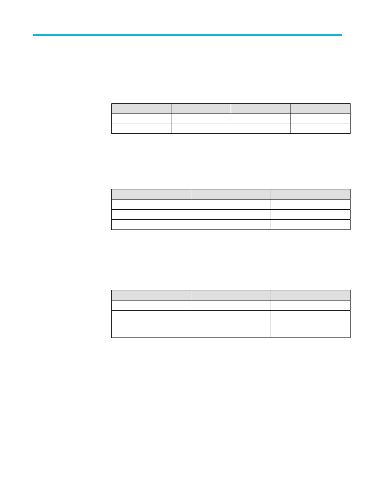
The following table lists the required equipment. You might need additional cables and adapters, depending on the actual test equipment
you use.
Required equipment Minimum requirements Examples
DC voltage source 3 mV to 4 V, ±0.1% accuracy Fluke 9500B Oscilloscope Calibrator with a 9530
Output Module
Leveled sine wave
generator
Time mark generator
50 kHz to 2 GHz, ±4% amplitude accuracy
80 ms period, ±1.0 x 10⁻⁶ accuracy, rise time <50 ns
24
Page 25

Test records
DC Gain Accuracy test record
DC Gain Accuracy
Performance
checks
Channel 1 DC Gain
Accuracy, 0 V offset,
0 V vertical position
Channel 2 DC Gain
Accuracy, 0 V offset,
0 V vertical position
Table continued…
Bandwidth Vertical scale Low limit Test result High limit
20 MHz 2 mV/div -2% 2%
FULL 100 mV/div -2% 2%
20 MHz 2 mV/div -2% 2%
FULL 100 mV/div -2% 2%
Performance verification procedures
4.98 mV/div -2% 2%
5 mV/div -2% 2%
10 mV/div -2% 2%
20 mV/div -2% 2%
49.8 mV/div -2% 2%
50 mV/div -2% 2%
100 mV/div -2% 2%
200 mV/div -2% 2%
500 mV/div -2% 2%
1 V/div -2% 2%
4.98 mV/div -2% 2%
5 mV/div -2% 2%
10 mV/div -2% 2%
20 mV/div -2% 2%
49.8 mV/div -2% 2%
50 mV/div -2% 2%
100 mV/div -2% 2%
200 mV/div -2% 2%
500 mV/div -2% 2%
1 V/div -2% 2%
2 Series Mixed Signal Oscilloscopes MSO22 and MSO24 Specifications and Performance Verification 25
Page 26

Performance verification procedures
DC Gain Accuracy
Performance
checks
Channel 3 DC Gain
Accuracy, 0 V offset,
0 V vertical position
Channel 4 DC Gain
Accuracy, 0 V offset,
0 V vertical position
Bandwidth Vertical scale Low limit Test result High limit
20 MHz 2 mV/div -2% 2%
FULL 100 mV/div -2% 2%
20 MHz 2 mV/div -2% 2%
FULL 100 mV/div -2% 2%
4.98 mV/div -2% 2%
5 mV/div -2% 2%
10 mV/div -2% 2%
20 mV/div -2% 2%
49.8 mV/div -2% 2%
50 mV/div -2% 2%
100 mV/div -2% 2%
200 mV/div -2% 2%
500 mV/div -2% 2%
1 V/div -2% 2%
4.98 mV/div -2% 2%
5 mV/div -2% 2%
10 mV/div -2% 2%
20 mV/div -2% 2%
49.8 mV/div -2% 2%
50 mV/div -2% 2%
100 mV/div -2% 2%
200 mV/div -2% 2%
500 mV/div -2% 2%
1 V/div -2% 2%
26
Page 27

Analog Bandwidth test record
Analog Bandwidth performance checks
Bandwidth at
Channel
Channel 1 1 mV/div ≥ 0.707
Channel 2 1 mV/div ≥ 0.707
Channel 3 1 mV/div ≥ 0.707
Table continued…
Vertical scale V
in-AC RMS
V
bw-AC RMS
Limit Test result Gain =
2 mV/div ≥ 0.707
5 mV/div ≥ 0.707
10 mV/div ≥ 0.707
20 mV/div ≥ 0.707
200 mV/div ≥ 0.707
700 mV/div ≥ 0.707
3 V/div ≥ 0.707
5 V/div ≥ 0.707
2 mV/div ≥ 0.707
5 mV/div ≥ 0.707
10 mV/div ≥ 0.707
20 mV/div ≥ 0.707
200 mV/div ≥ 0.707
700 mV/div ≥ 0.707
3 V/div ≥ 0.707
5 V/div ≥ 0.707
2 mV/div ≥ 0.707
5 mV/div ≥ 0.707
10 mV/div ≥ 0.707
20 mV/div ≥ 0.707
200 mV/div ≥ 0.707
700 mV/div ≥ 0.707
3 V/div ≥ 0.707
5 V/div ≥ 0.707
Performance verification procedures
V
bw-AC RMS/Vin-AC RMS
2 Series Mixed Signal Oscilloscopes MSO22 and MSO24 Specifications and Performance Verification 27
Page 28

Performance verification procedures
Analog Bandwidth performance checks
Bandwidth at
Channel
Vertical scale V
in-AC RMS
V
bw-AC RMS
Limit Test result Gain =
V
bw-AC RMS/Vin-AC RMS
Channel 4 1 mV/div ≥ 0.707
2 mV/div ≥ 0.707
5 mV/div ≥ 0.707
10 mV/div ≥ 0.707
20 mV/div ≥ 0.707
200 mV/div ≥ 0.707
700 mV/div ≥ 0.707
3 V/div ≥ 0.707
5 V/div ≥ 0.707
Digital threshold accuracy tests with 2-MSO option
Digital threshold accuracy performance checks
Test result V
Digital channel Threshold
V
s-
V
s+
Low limit
(V
+ Vs+)/2
s--
D0 0 V -0.18 V 0.18 V
4 V 3.74 V 4.26 V
D1 0 V -0.18 V 0.18 V
4 V 3.74 V 4.26 V
D2 0 V -0.18 V 0.18 V
4 V 3.74 V 4.26 V
D3 0 V -0.18 V 0.18 V
4 V 3.74 V 4.26 V
D4 0 V -0.18 V 0.18 V
4 V 3.74 V 4.26 V
D5 0 V -0.18 V 0.18 V
4 V 3.74 V 4.26 V
D6 0 V -0.18 V 0.18 V
4 V 3.74 V 4.26 V
D7 0 V -0.18 V 0.18 V
4 V 3.74 V 4.26 V
D8 0 V -0.18 V 0.18 V
4 V 3.74 V 4.26 V
D9 0 V -0.18 V 0.18 V
4 V 3.74 V 4.26 V
Table continued…
sAvg
=
High limit
28
Page 29

Performance verification procedures
Digital threshold accuracy performance checks
Test result V
Digital channel Threshold
D10 0 V -0.18 V 0.18 V
4 V 3.74 V 4.26 V
D11 0 V -0.18 V 0.18 V
4 V 3.74 V 4.26 V
D12 0 V -0.18 V 0.18 V
4 V 3.74 V 4.26 V
D13 0 V -0.18 V 0.18 V
4 V 3.74 V 4.26 V
D14 0 V -0.18 V 0.18 V
4 V 3.74 V 4.26 V
D15 0 V -0.18 V 0.18 V
4 V 3.74 V 4.26 V
V
s-
V
s+
Low limit
(V
+ Vs+)/2
s--
sAvg
=
High limit
Long term sample rate test records
Long Term Sample Rate
Performance checks Low limit Test result High limit
Long Term Sample Rate -2 divisions +2 divisions
AFG DC Offset Accuracy Tests
AFG DC Offset Accuracy
Performance checks Low limit Test result High limit
All models 20 mV DC offset @ 50 Ω 18.7 mV 21.3 mV
1 V DC offset @ 50 Ω 984 mV 1.016 V
- 1 V DC offset @ 50 Ω -1.016 V -984 mV
Check probe compensation
Procedure to check the probe compensation.
Procedure
1. Connect the probe compensation to Ch 1.
2. Turn on the Ch 1 and turn off all other channels.
3. Tap File > Default Setup.
4. Push Autoset button on the front-panel or tap File > Autoset from the menu bar.
The screen displays a square wave. The levels should be approximately 0 V - 2.5 V and 1 kHz.
2 Series Mixed Signal Oscilloscopes MSO22 and MSO24 Specifications and Performance Verification 29
Page 30

Performance verification procedures
Check Aux In
Procedure to check the Aux In.
Procedure
1. Connect probe compensation to Aux In.
2. Tap File > Default Setup.
3. Double-tap the trigger badge on the settings bar and set the trigger Source to Aux In.
4. Set Trigger Level to 1 V.
5. Tap Trigger on the settings bar and verify the oscilloscope is Triggering.
Check DC gain accuracy
Procedure to test the DC gain accuracy.
Procedure
WARNING:
performance of this procedure. The generator is capable of providing dangerous voltages.
1. Connect the oscilloscope to a calibrated DC voltage source. If you are using the Fluke 9500 calibrator, connect the calibrator head to
the oscilloscope channel to test.
Set the generator output to Off or 0 volts before connecting, disconnecting, and/or moving the test hookup during the
30
Page 31

Performance verification procedures
2. Tap File > Default Setup.
3. Double-tap the Acquisition badge and set Acquisition Mode to Average.
4. Set the Number of Waveforms to 16.
5. Tap outside the menu to close the menu.
6. Double-tap the Trigger badge and set the trigger Source to Internal.
7. Tap outside the menu to close it.
8. Add the Mean measurement to the Results bar:
a) Tap the Measure button to open the Add Measurements menu.
b) Set the Source to Ch 1.
c) In the Amplitude Measurements panel, double-tap the Mean button to add the Mean measurement badge to the Results bar.
9. Tap outside the menu to close it.
10. Double-tap the Mean results badge.
11. Tap Show Statistics in Badge.
12. Tap outside the menu to close it.
13. Tap the channel button of the channel to test, to add the channel badge to the Settings bar.
14. Double tap the channel to test badge to open its menu and set the channel settings:
a) Set Vertical Scale to 2 mV/div.
b) Tap Bandwidth Limit and set to 20 MHz.
c) Tap outside the menu to close it.
15. Record the negative-measured and positive-measured mean readings in the Expected gain worksheet as follows:
a) On the calibrator, set the DC Voltage Source to the V
value as listed in the 2 mV row of the worksheet.
negative
b) Double-tap the Acquisition badge and tap Clear to reset the measurement statistics.
c) Enter the Mean reading in the worksheet as V
negative-measured
d) On the calibrator, set the DC Voltage Source to V
positive
.
value as listed in the 2 mV row of the worksheet.
e) Double-tap the Acquisition badge (if not open) and tap Clear.
f) Enter the Mean reading in the worksheet as V
positive-measured
.
2 Series Mixed Signal Oscilloscopes MSO22 and MSO24 Specifications and Performance Verification 31
Page 32

Performance verification procedures
Table 1: Expected gain worksheet
Oscilloscope
vertical scale
setting
V
diffExpected
V
negative
V
positive
V
negative-
measured
V
positive-
measured
V
diff
Test result
(Gain
accuracy)
2 mV/div
4.98 mV/div
5 mV/div
10 mV/div
20 mV/div
49.8 mV/div
50 mV/div
100 mV/div
200 mV/div
500 mV/div
1.0 V/div
100 mV/div at
Full BW
16. Calculate Gain Accuracy as follows:
a) Calculate V
V
= | V
diff
b) Enter V
as follows:
diff
negative-measured
in the worksheet.
diff
- V
positive-measured
|
c) Calculate Gain Accuracy as follows:
Gain Accuracy = ((V
diff
- V
diffExpected
)/V
diffExpected
) × 100%
d) Enter the Gain Accuracy value in the worksheet and in the test record.
17. Repeat steps 14 on page 31 through 16 on page 32 for all vertical scale settings in the work sheet and the test record.
18. Repeat the procedure for all remaining channels:
a) Set the calibrator to 0 volts.
b) Move the calibrator output to the next channel input to be tested.
c) Double-tap the channel badge of the channel that you have finished testing and set Display to Off.
d) Double-tap the Mean measurement badge.
e) Tap the Configure panel.
f) Tap the Source 1 field and select the next channel to test.
g) Starting from step 14 on page 31, set the values from the test record for the channel under test, and repeat the above steps until
all channels have been tested.
19. Touch outside a menu to close the menu.
Check analog bandwidth
Procedure to check the bandwidth for each channel.
Procedure
WARNING:
performance of this procedure. The generator is capable of providing dangerous voltages.
32
Set the generator to off or 0 volts before connecting, disconnecting, and/or moving the test hookup during the
Page 33

Performance verification procedures
1. Connect the output of the calibrated leveled sine wave generator to the 50 Ω terminator (Tektronix Part Number 011-0049-02) on
Channel 1 as shown in the following illustration.
If using the Fluke 9500 calibrator as the sine wave generator, connect the calibrator head to the 50 Ω terminator with the Fluke 9500
in 50 Ω output mode. Do not connect the Fluke 9500 calibrator head directly to the oscilloscope channel.
2. Tap File > Default Setup to reset the instrument and add the channel 1 badge and signal to the display.
3. Add the AC RMS measurement as follows:
a) Tap the Measure button.
b) Set the Source to the channel under test.
c) In the Amplitude Measurements panel, double-tap the AC RMS measurement button to add the measurement badge to the
Results bar.
4. Set the channel under test settings:
a) Double-tap the badge of the channel under test to open its configuration menu.
b) Set Vertical Scale to 1 mV/div.
c) Tap outside the menu to close it.
5. Adjust the leveled sine wave signal source to display a waveform of 8 vertical divisions at the selected vertical scale with a set
frequency of 1 kHz.
For example, at 5 mV/div, use a ≥40 mV
signal; at 2 mV/div, use a ≥16 mV
p-p
signal.
p-p
At some V/div settings, the generator may not provide 8 vertical divisions of signal. Set the generator output to obtain as many
vertical divisions of signal as possible.
6. Double-tap the Horizontal badge in the Settings bar.
7. Set the Horizontal Scale to 1 ms/division.
8. Tap outside the menu to close it.
9. Record the AC RMS measurement in the V
in-AC RMS
entry of the test record.
10. Double-tap the Horizontal badge in the Settings bar.
11. Set the Horizontal Scale to 4 ns/division.
12. Adjust the signal source to the maximum bandwidth frequency for the bandwidth and model being tested.
13. Record the AC RMS measurement at the new frequency in the V
entry of the test record.
bw-pp
14. Use the values of V bw-pp and V in-pp recorded in the test record, and the following equation, to calculate the Gain at bandwidth.
Gain = Vbw-pp / Vin-pp.
To pass the performance measurement test, Gain should be ≥ 0.707. Enter Gain in the test record.
15. Repeat steps from 4 on page 33 to 14 on page 33 for all combinations of Vertical Scale and Horizontal Scale settings listed in the test
record.
16. Repeat the test for all remaining channels as follows:
2 Series Mixed Signal Oscilloscopes MSO22 and MSO24 Specifications and Performance Verification 33
Page 34

Performance verification procedures
a) Turn Off the generator.
b) Move the calibrator output to the next channel input to be tested.
c) Turn On the generator.
d) Tap the channel button on the oscilloscope Settings bar of the next channel to test.
e) Double-tap the AC RMS measurement badge.
f) Tap the Configure panel.
g) Tap the Source 1 field and select the next channel to test.
h) Starting from step 4 on page 33, repeat the procedure until all channels have been tested.
Check digital threshold accuracy with 2-MSO option
This procedure checks the threshold accuracy of the digital channels and is for models with the 2-MSO option only.
About this task
This procedure applies to digital channels D0 through D15, and to channel threshold values of 0 V and 4 V.
Procedure
1. Connect the P6316 digital probe to the instrument.
2. Connect the P6316 Group 1 pod to the DC voltage source to run this test.
You will need a BNC-to-0.1 inch pin adapter to complete the connection. If using the Fluke 9500 calibrator as the DC voltage source,
connect the calibrator head to the P6316 Group 1 pod. You will need a BNC-to-0.1 inch pin adapter to complete the connection.
3. Push Default Setup on the front panel to set the instrument to the factory default settings.
4. Display the digital channels and set the thresholds as follows:
a) Tap the D15-D0 button on the Settings bar.
b) Double-tap the D15-D0 badge on the Settings bar.
c) Tap the D15-D8 Turn All On button to turn all bits on.
d) Tap the D7-D0 Turn All On button to turn all bits on.
e) Tap the D15-D8 Thresholds field at the bottom of the menu and set the value to 0 V.
f) Tap the D7-D0 field at the bottom of the menu and set the value to 0 V. The thresholds are set for the 0 V threshold check.
34
Page 35

Performance verification procedures
g) Tap outside the menu to close it.
5. You need to record the test values in the test record row for 0 V for each digital channel. See Digital threshold accuracy performance
checks table.
6. Double-tap the Trigger badge.
7. Tap Slope and change the slope to rising edge.
8. Set the Source to the appropriate channel, such as D0.
By default, the Type is set to Edge, Coupling is set to DC, Slope is set to Rising, Mode is set to Auto, and Level is set to match the
threshold of the channel being tested.
9. Tap outside the menu to close it.
10. Set the DC voltage source (Vs) to -400 mV. Wait 3 seconds. Check the logic level of the corresponding digital channel in the display.
If the channel is a static logic level high (green), change the DC voltage source Vs to -500 mV.
11. Increment Vs by +20 mV. Wait 3 seconds and check the logic level of the corresponding digital channel in the display. If the channel
is at a static logic level high (green), record the Vs value as in the 0 V row of the test record.
If the channel is a logic level low (blue) or is alternating between high and low, repeat this step (increment Vs by 20 mV, wait
3 seconds, and check for a static logic high). Continue until a value for Vs- is found. In this procedure, the channel might not change
state until after you pass the set threshold level.
12. Double-tap the Trigger badge.
13. Tap Slope and change the slope to falling edge.
14. Tap outside the menu to close it.
15. Set the DC voltage source (Vs) to +400 mV. Wait 3 seconds. Check the logic level of the corresponding digital channel in the display.
If the channel is a static logic level low (blue), change the DC voltage source Vs to +500 mV.
16. Decrement Vs by -20 mV. Wait 3 seconds and check the logic level of the corresponding digital channel in the display. If the channel
is at a static logic level low, record the Vs value as Vs+ in the 0 V row of the test record.
If the channel is a logic level high (green) or is alternating between high and low, repeat this step (decrement Vs by 20 mV, wait
3 seconds, and check for a static logic low). Continue until a value for Vs+ is found.
17. Find the average, V
= (Vs- + Vs+)/2. Record the average as the test result in the test record.
sAvg
Compare the test result to the limits. If the result is between the limits, continue with the procedure to test the channel at the +4 V
threshold value.
18. Repeat the procedure starting with step 6 on page 35 for each remaining digital channel.
19. Double-tap the Trigger badge.
20. Set the Source to the appropriate channel, such as D0.
21. Tap Slope and change the slope to falling edge.
22. The remaining part of this procedure is for the +4 V threshold test.
a) Double-tap the D15-D0 badge on the Settings bar.
b) Tap the D15-D8 Turn All On button to turn all bits on.
c) Tap the D7-D0 Turn All On button to turn all bits on.
d) Tap the D15-D8 Thresholds field at the bottom of the menu and set the value to 4.00 V.
e) Tap the D7-D0 Thresholds field at the bottom of the menu and set the value to 4.00 V.
f) Tap outside the menu to close it.
23. Set the DC voltage source (Vs) to +4.4 V. Wait 3 seconds. Check the logic level of the corresponding digital channel in the display.
If the channel is a static logic level low (blue), change the DC voltage source Vs to +4.5 V.
24. Decrement Vs by -20 mV. Wait 3 seconds and check the logic level of the corresponding digital channel in the display. If the channel
is at a static logic level low, record the Vs value as Vs+ in the 4 V row of the test record.
If the channel is a logic level high (green) or is alternating between high and low, repeat this step (decrement Vs by 20 mV, wait
3 seconds, and check for a static logic low). Continue until a value for Vs+ is found.
2 Series Mixed Signal Oscilloscopes MSO22 and MSO24 Specifications and Performance Verification 35
Page 36

Performance verification procedures
25. Double-tap the Trigger badge.
26. Tap Slope and change the slope to rising edge.
27. Tap outside the menu to close it.
28. Set the DC voltage source (Vs) to +3.6 V. Wait 3 seconds. Check the logic level of the corresponding digital channel in the display.
If the channel is a static logic level high (green), change the DC voltage source Vs to +3.5 V.
29. Increment Vs by +20 mV. Wait 3 seconds and check the logic level of the corresponding digital channel in the display. If the channel
is at a static logic level high, record the Vs value as in the 4 V row of the test record.
If the channel is a logic level low (blue) or is alternating between high and low, repeat this step (increment Vs by 20 mV, wait
3 seconds, and check for a static logic high). Continue until a value for Vs- is found.
30. Find the average, V
Compare the test result to the limits. If the result is between the limits, the channel passes the test.
31. Repeat the procedure starting with step 19 on page 35 for each digital channel.
= (Vs- + Vs+)/2. Record the average as the test result in the test record.
sAvg
Check long term sample rate
This procedure checks the sample rate and delay time accuracy (time base).
Procedure
WARNING: Set the generator to off or 0 volts before connecting, disconnecting, and/or moving the test hookup during the
performance of this procedure. The generator is capable of providing dangerous voltages.
1. Connect the output of a time mark generator to the oscilloscope channel 1 input.
2. Set the time mark generator period to 80 ms. Use a time mark waveform with a fast rising edge.
3. If it is adjustable, set the time mark amplitude to approximately 1 V
4. Tap File > Default Setup.
5. Tap the channel 1 button on the Settings bar.
6. Double-tap the Channel 1 badge to open its Configuration menu.
7. Set Vertical Scale to 500 mV.
8. Set the Position value to center the time mark signal on the screen.
9. Tap outside the menu area to close it.
10. Double-tap the Horizontal settings badge.
11. Set the Horizontal Scale to 1 us/div.
12. Tap outside the menu area to close it.
13. Double-tap the Trigger settings badge.
36
P-P
.
Page 37

Performance verification procedures
14. Set Source to the channel being tested.
15. Set the Level as necessary for a triggered display.
16. Tap outside the menu area to close it.
17. Double-tap the Horizontal settings badge.
18. Adjust the Position value to move the trigger point to the center of the screen.
19. Turn Delay to On and set Position to 80 ms.
20. Set the Horizontal Scale to 1 us/div.
21. Observe where the rising edge of the marker crosses the center horizontal graticule line. The rising edge should cross within ±2
divisions of the vertical center graticule. Enter the deviation in the test record.
A 2.5 x 10⁻⁶ time base error is 2 divisions of displacement.
Check AFG DC offset accuracy
This procedure checks the AFG DC Offset Accuracy.
Procedure
1. Connect the AFG output to the DMM through a 50 Ω termination.
2. Push the Default Setup button on the oscilloscope front panel.
3. Tap the AFG button.
4. Tap Waveform Type and select DC from the drop down list.
5. Tap Amplitude and set amplitude to the value shown in the test record.
6. Set DMM to measure DC Voltage.
7. Measure voltage on the DMM. Compare the result to the limits in the test record.
8. Repeat steps from 3 on page 37 to 7 on page 37 above for each line in the test record. This completes the procedure.
2 Series Mixed Signal Oscilloscopes MSO22 and MSO24 Specifications and Performance Verification 37
 Loading...