

Page 1

2 Series Mixed Signal Oscilloscopes
MSO22 and MSO24
Help
Register now!
Click the following link to protect your product.
www.tek.com/register
*P077171600*
077-1716-00
Page 2

Copyright © Tektronix. All rights reserved. Licensed software products are owned by Tektronix or its subsidiaries or suppliers, and are
protected by national copyright laws and international treaty provisions. Tektronix products are covered by U.S. and foreign patents, issued
and pending. Information in this publication supersedes that in all previously published material. Specifications and price change privileges
reserved.
TEKTRONIX and TEK are registered trademarks of Tektronix, Inc.
FlexChannel, TekVPI, FastAcq, and e*Scope are registered trademarks of Tektronix, Inc.
FastFrame and TekSecure are trademarks of Tektronix, Inc.
Contacting Tektronix
Tektronix, Inc.
14150 SW Karl Braun Drive
P.O. Box 500
Beaverton, OR 97077
USA
For product information, sales, service, and technical support:
• In North America, call 1-800-833-9200.
• Worldwide, visit www.tek.com to find contacts in your area.
Page 3

Table of Contents
Table of Contents
TEKTRONIX END USER LICENSE AGREEMENT....................................................................................................................10
Open Source GPL License Notice.............................................................................................................................................. 16
Instrument compliance markings................................................................................................................................................ 17
Welcome to the 2 Series MSO Help............................................................................................................................................18
Product documents and support................................................................................................................................................. 19
Product support and feedback............................................................................................................................................. 19
Product Documentation....................................................................................................................................................... 19
Installing your instrument............................................................................................................................................................ 21
Install option upgrade licenses.............................................................................................................................................21
Operating requirements....................................................................................................................................................... 21
Input signal requirements.....................................................................................................................................................22
Check that the instrument passes power-on self tests........................................................................................................ 22
Battery pack information...................................................................................................................................................... 22
Battery pack installation................................................................................................................................................23
Operating safely with battery power..............................................................................................................................24
Rechargeable battery installation..................................................................................................................................25
Rechargeable battery removal......................................................................................................................................26
Battery status................................................................................................................................................................26
Instrument stand to battery pack installation.................................................................................................................28
Connecting probes to the instrument................................................................................................................................... 29
Rackmount option information............................................................................................................................................. 29
Getting acquainted with your instrument.....................................................................................................................................30
Front panel controls and connectors....................................................................................................................................30
Button and knob functions................................................................................................................................................... 31
Rear and side panel connections.........................................................................................................................................33
Instrument stand installation................................................................................................................................................ 35
User interface.......................................................................................................................................................................36
User interface elements....................................................................................................................................................... 38
Badges.................................................................................................................................................................................39
Moving waveform and measurement badges...................................................................................................................... 45
Group signal badges in the Settings bar..............................................................................................................................46
Configuration menus............................................................................................................................................................46
Zoom user interface............................................................................................................................................................. 47
Using the touch screen interface for common tasks............................................................................................................ 49
Accessing application help...................................................................................................................................................50
Configure the instrument.............................................................................................................................................................51
Download and install the latest instrument firmware............................................................................................................51
Set the time zone and clock readout format........................................................................................................................ 51
Functional check.................................................................................................................................................................. 52
Run Signal Path Compensation (SPC)................................................................................................................................ 52
Compensate the TPP Series probes................................................................................................................................... 53
Compensate passive probes............................................................................................................................................... 53
Connect to a network (LAN).................................................................................................................................................53
Mount a network drive from a standard instrument..............................................................................................................54
2 Series Mixed Signal Oscilloscopes MSO22 and MSO24 Help 3
Page 4

Table of Contents
Mount a TekDrive on the instrument.................................................................................................................................... 54
Unmount a network drive from a standard instrument......................................................................................................... 55
Unmount a TekDrive from the instrument............................................................................................................................ 55
Connect the oscilloscope to a PC using a USB cable......................................................................................................... 55
Deskew analog input channels - quick visual method......................................................................................................... 56
Deskew analog input channels - measurement method...................................................................................................... 56
Connect a keyboard or mouse.............................................................................................................................................57
ESD Prevention Guidelines................................................................................................................................................. 57
Analog channel operating basics................................................................................................................................................ 58
Acquiring a signal.................................................................................................................................................................58
Autoset to quickly display a waveform................................................................................................................................. 58
Set Horizontal parameters .................................................................................................................................................. 59
How to trigger on a signal.................................................................................................................................................... 60
Set the acquisition mode......................................................................................................................................................61
Start and stop an acquisition................................................................................................................................................61
Add a channel waveform to the display............................................................................................................................... 62
Configure channel or waveform settings..............................................................................................................................63
Add a math, reference, or bus waveform.............................................................................................................................63
Add a measurement.............................................................................................................................................................64
Configure a measurement................................................................................................................................................... 66
Delete a Measurement or Search badge............................................................................................................................. 68
Display an XY plot................................................................................................................................................................68
Display an FFT math waveform........................................................................................................................................... 68
Add a serial bus to the Waveform view................................................................................................................................68
Add a parallel bus to the Waveform view.............................................................................................................................70
Add a Search....................................................................................................................................................................... 71
Change waveform view settings.......................................................................................................................................... 73
Display and configure cursors..............................................................................................................................................74
Using Default Setup............................................................................................................................................................. 76
Add a callout to a view......................................................................................................................................................... 76
Delete a Callout................................................................................................................................................................... 77
Advanced triggering.................................................................................................................................................................... 78
Triggering concepts..............................................................................................................................................................78
Trigger on a pulse width event.............................................................................................................................................78
Trigger on a timeout event................................................................................................................................................... 79
Trigger on a runt signal event.............................................................................................................................................. 80
Trigger on a logic event........................................................................................................................................................81
Trigger on a setup-hold event.............................................................................................................................................. 82
Trigger on a rise or fall time event........................................................................................................................................82
Set up trigger on a parallel bus............................................................................................................................................ 83
Set up trigger on a serial bus............................................................................................................................................... 84
Set Trigger Holdoff...............................................................................................................................................................84
Trigger on an external signal using the AUX input...............................................................................................................84
Setting waveform display parameters......................................................................................................................................... 85
Set waveform display mode (Stacked or Overlay)...............................................................................................................85
Set the Waveform Interpolation mode..................................................................................................................................85
Set the waveform persistence, style, and intensity.............................................................................................................. 85
Set the graticule style and intensity..................................................................................................................................... 86
Mask testing waveforms..............................................................................................................................................................87
2 Series Mixed Signal Oscilloscopes MSO22 and MSO24 Help 4
Page 5

Table of Contents
Create a Mask......................................................................................................................................................................87
Edit mask segments on the screen......................................................................................................................................87
Edit mask segments using the Mask Definition menu......................................................................................................... 89
Zoom in on waveforms................................................................................................................................................................92
Turn on Zoom mode.............................................................................................................................................................92
Using Wave Inspector front-panel controls for zoom........................................................................................................... 93
Zoom mode and Searches...................................................................................................................................................93
Measurement configuration.........................................................................................................................................................94
Label a measurement.......................................................................................................................................................... 94
Set measurement reference levels...................................................................................................................................... 94
Set measurement gates.......................................................................................................................................................95
Saving and recalling information................................................................................................................................................. 97
Save a screen image........................................................................................................................................................... 97
Save a waveform to a file.....................................................................................................................................................97
Save instrument settings to a file......................................................................................................................................... 98
Save reports.........................................................................................................................................................................98
Save sessions......................................................................................................................................................................99
Recall a reference waveform............................................................................................................................................... 99
Recall a Setup file.............................................................................................................................................................. 100
Recall a Session file...........................................................................................................................................................101
Menus and dialog boxes........................................................................................................................................................... 102
Act On Event configuration menu...................................................................................................................................... 102
Add Measurements configuration menu overview............................................................................................................. 103
The Measurements tab...............................................................................................................................................104
Amplitude Measurements panel................................................................................................................................. 104
Time Measurements panel......................................................................................................................................... 105
Measurement configuration menu overview...................................................................................................................... 108
Measurement Name panel (Measurement configuration menu).................................................................................108
Configure panel (Measurement configuration menu)..................................................................................................109
Reference Levels panel (Measurement configuration menu)..................................................................................... 110
Gating panel (Measurement configuration menu)....................................................................................................... 111
Pass/Fail Testing panel (Measurement Settings menu)..............................................................................................112
Bus configuration menu......................................................................................................................................................113
Parallel Bus configuration menu................................................................................................................................. 113
Parallel Bus - Define Inputs menu...............................................................................................................................115
I2C serial bus configuration menu...............................................................................................................................115
SPI serial bus configuration menu.............................................................................................................................. 116
RS232 serial bus menu...............................................................................................................................................118
CAN serial bus configuration menu.............................................................................................................................119
LIN serial bus configuration menu.............................................................................................................................. 121
SENT serial bus configuration menu.......................................................................................................................... 122
Add Plot configuration menu..............................................................................................................................................124
Add Results Table configuration menu.............................................................................................................................. 124
Results Tables operations overview............................................................................................................................124
Measurement Table configuration menu.....................................................................................................................125
Save As configuration menu (Measurement Results Table).......................................................................................126
Search Results table menu.........................................................................................................................................126
Save As configuration menu (Search Results table).................................................................................................. 127
Bus Decode Results table configuration menu...........................................................................................................128
2 Series Mixed Signal Oscilloscopes MSO22 and MSO24 Help 5
Page 6

Table of Contents
Save As configuration menu (Bus Decode Results table).......................................................................................... 129
Search configuration menu overview.................................................................................................................................129
Bus Search configuration menus................................................................................................................................130
Parallel bus search configuration menu......................................................................................................................130
I2C serial bus search configuration menu...................................................................................................................131
SPI serial bus search configuration menu.................................................................................................................. 132
RS-232 serial bus search configuration menu............................................................................................................133
CAN serial bus search configuration menu (when not using a .dbc symbol definition file).........................................134
CAN serial bus search configuration menu (when using a .dbc symbol definition file)...............................................136
CAN DBC Symbolic Configuration menu....................................................................................................................138
LIN serial bus search configuration menu...................................................................................................................138
SENT serial bus search configuration menu...............................................................................................................139
Configure pattern editor.............................................................................................................................................. 141
Edge Search configuration menu................................................................................................................................142
Logic search configuration menu................................................................................................................................143
Logic Search - Define Inputs configuration menu.......................................................................................................145
Pulse Width Search configuration menu.....................................................................................................................145
Rise/Fall Time Search configuration menu.................................................................................................................146
Runt Search configuration menu................................................................................................................................ 148
Setup and Hold Search configuration menu............................................................................................................... 149
Setup and Hold Search - Define Inputs configuration menu.......................................................................................150
Timeout Search configuration menu...........................................................................................................................150
Analog Channel configuration menu..................................................................................................................................151
Invert channel guidelines............................................................................................................................................ 152
AFG configuration menu.................................................................................................................................................... 153
Cursor configuration menu.................................................................................................................................................155
Date and Time configuration menu....................................................................................................................................156
More (DRAW A BOX Menu)...............................................................................................................................................157
Mask Badge configuration menu....................................................................................................................................... 157
Mask Definition configuration menu...................................................................................................................................157
Right click menu functions associated with mask segments..............................................................................................160
Mask Test badge configuration menu................................................................................................................................ 161
Right click menu functions associated with the Mask Test badge..................................................................................... 162
Math configuration menu overview.................................................................................................................................... 162
Math configuration menu............................................................................................................................................ 162
Equation Editor (Math configuration menu)................................................................................................................ 164
Add Functions (math Equation Editor) .......................................................................................................................165
Menu bar overview.............................................................................................................................................................166
Recall configuration menu (File menu)....................................................................................................................... 166
Save As configuration menu (File menu)....................................................................................................................168
Browse Save As Location configuration menu........................................................................................................... 171
File Utilities configuration (File menu).........................................................................................................................172
Mount Drive configuration menu.................................................................................................................................173
Undo, Redo (Edit menu)............................................................................................................................................. 174
User Preferences (Utility menu)..................................................................................................................................174
Define Custom Colors menu.......................................................................................................................................178
I/O (Utility menu).........................................................................................................................................................179
LAN Reset configuration menu (Utility > I/O menu)....................................................................................................182
Self Test configuration menu (Utility menu)................................................................................................................ 182
2 Series Mixed Signal Oscilloscopes MSO22 and MSO24 Help 6
Page 7

Table of Contents
Calibration configuration menu (Utility menu).............................................................................................................183
Security configuration menu for standard instruments (Utility menu)......................................................................... 183
TekSecure Erase Memory...........................................................................................................................................184
Demo (Utility menu).................................................................................................................................................... 184
Help... (Help menu).....................................................................................................................................................185
License Options...(Help menu)................................................................................................................................... 185
About (Help menu)......................................................................................................................................................185
Location to Save Exit Key configuration menu........................................................................................................... 185
Browse License Files menu (Help > About)................................................................................................................186
Font Color menu (Text Settings configuration)...................................................................................................................188
Text Settings configuration menu (Callout and Waveform labels text)...............................................................................188
Plot configuration menus................................................................................................................................................... 188
Plot XY configuration menu........................................................................................................................................ 188
Save As configuration menu (plot Save panel, Save Plot Image button)................................................................... 189
Save As configuration menu (plot Save panel, Save Plot Data button)......................................................................190
Reference waveform configuration menu.......................................................................................................................... 190
Recall configuration menu (Ref waveform configuration menu)................................................................................. 191
Search configuration menu................................................................................................................................................ 192
Trigger configuration menu overview.................................................................................................................................193
Edge Trigger configuration menu................................................................................................................................193
Pulse Width Trigger configuration menu.....................................................................................................................194
Timeout Trigger configuration menu...........................................................................................................................195
Runt Trigger configuration menu................................................................................................................................ 196
Logic Trigger configuration menu............................................................................................................................... 197
Logic Trigger - Define Inputs configuration menu.......................................................................................................198
Setup and Hold Trigger configuration menu............................................................................................................... 198
Setup and Hold Trigger - Define Inputs configuration menu.......................................................................................199
Rise/Fall Time Trigger configuration menu.................................................................................................................199
Bus Trigger configuration............................................................................................................................................200
Virtual Keyboard.................................................................................................................................................................209
Bus trigger radix-specific virtual keypads...........................................................................................................................209
Virtual Keypad....................................................................................................................................................................210
Waveform View configuration menu.................................................................................................................................. 210
The Horizontal and Acquisition configuration menu...........................................................................................................212
Waveform acquisition................................................................................................................................................................215
Acquisition concepts.......................................................................................................................................................... 215
Acquisition hardware...................................................................................................................................................215
Sampling process....................................................................................................................................................... 215
Real-Time sampling....................................................................................................................................................215
Interpolated Real-Time sampling................................................................................................................................216
Waveform record........................................................................................................................................................ 216
Interpolation................................................................................................................................................................ 216
Acquisition modes..............................................................................................................................................................217
Waveform sample interpolation..........................................................................................................................................217
Coupling.............................................................................................................................................................................217
Scaling and positioning...................................................................................................................................................... 218
Vertical acquisition considerations.....................................................................................................................................218
Horizontal acquisition considerations.................................................................................................................................219
Triggering concepts...................................................................................................................................................................220
2 Series Mixed Signal Oscilloscopes MSO22 and MSO24 Help 7
Page 8

Table of Contents
Trigger sources.................................................................................................................................................................. 220
Trigger types...................................................................................................................................................................... 220
Trigger modes....................................................................................................................................................................221
Trigger holdoff....................................................................................................................................................................221
Trigger coupling................................................................................................................................................................. 222
Trigger slope and level.......................................................................................................................................................222
Trigger position in waveform record...................................................................................................................................222
Advanced triggering........................................................................................................................................................... 222
Bus triggering concepts.............................................................................................................................................. 223
Pulse width trigger concepts.......................................................................................................................................223
Timeout trigger concepts............................................................................................................................................ 223
Runt trigger concepts..................................................................................................................................................223
Logic trigger concepts.................................................................................................................................................223
Setup and Hold trigger concepts.................................................................................................................................223
Rise/Fall time trigger concepts....................................................................................................................................224
Waveform display overview.......................................................................................................................................................225
Waveform preview mode................................................................................................................................................... 225
Horizontal position and the horizontal reference point.......................................................................................................225
Measurement concepts.............................................................................................................................................................226
Measurement variables......................................................................................................................................................226
Missing or out-of-range samples........................................................................................................................................228
Math waveforms.................................................................................................................................................................228
Math waveform elements...................................................................................................................................................229
Math waveform sources.....................................................................................................................................................230
Guidelines for working with math waveforms.....................................................................................................................230
Math waveform editor syntax............................................................................................................................................. 230
Math waveform differentiation............................................................................................................................................231
Math waveform offset, position, and scale.........................................................................................................................231
Waveform integration.........................................................................................................................................................232
FFT process.......................................................................................................................................................................232
FFT and aliasing................................................................................................................................................................ 233
Blackman-Harris FFT window concepts.............................................................................................................................234
Flattop2 window................................................................................................................................................................. 234
Gaussian window...............................................................................................................................................................235
Hanning FFT window......................................................................................................................................................... 235
Hamming window...............................................................................................................................................................236
Kaiser-Bessel FFT window................................................................................................................................................ 236
Rectangular window...........................................................................................................................................................237
Tek-Exponential window.................................................................................................................................................... 237
Measurement algorithms...........................................................................................................................................................239
Amplitude measurement algorithms.................................................................................................................................. 239
AC RMS measurement algorithm............................................................................................................................... 239
Area measurement algorithm......................................................................................................................................239
Amplitude measurement algorithm............................................................................................................................. 239
Base measurement algorithm.....................................................................................................................................239
Integration algorithm................................................................................................................................................... 239
Maximum measurement algorithm..............................................................................................................................240
Mean measurement algorithm.................................................................................................................................... 240
Minimum measurement algorithm...............................................................................................................................240
2 Series Mixed Signal Oscilloscopes MSO22 and MSO24 Help 8
Page 9

Table of Contents
Negative Overshoot measurement algorithm............................................................................................................. 240
Positive Overshoot measurement algorithm...............................................................................................................240
Peak-To-Peak measurement algorithm.......................................................................................................................241
RMS measurement algorithm..................................................................................................................................... 241
Top measurement algorithm....................................................................................................................................... 241
Time measurement algorithms...........................................................................................................................................241
Burst Width measurement algorithm...........................................................................................................................241
Data Rate measurement algorithm.............................................................................................................................241
Delay measurement algorithm....................................................................................................................................241
Falling slew rate..........................................................................................................................................................241
Fall Time measurement algorithm.............................................................................................................................. 242
Frequency measurement algorithm............................................................................................................................ 242
High Time measurement algorithm.............................................................................................................................243
Hold Time measurement algorithm.............................................................................................................................243
Low Time measurement algorithm..............................................................................................................................243
N-Periods Duration measurement algorithm...............................................................................................................243
Negative Duty Cycle measurement algorithm.............................................................................................................244
Negative Pulse Width measurement algorithm...........................................................................................................244
Period measurement algorithm...................................................................................................................................244
Phase measurement algorithm...................................................................................................................................244
Positive Duty Cycle measurement algorithm.............................................................................................................. 245
Positive Pulse Width measurement algorithm............................................................................................................ 245
Rising Slew Rate measurement algorithm..................................................................................................................245
Rise Time measurement algorithm.............................................................................................................................245
Setup.......................................................................................................................................................................... 246
Skew........................................................................................................................................................................... 246
Time Outside Level measurement algorithm.............................................................................................................. 247
Time to Max................................................................................................................................................................ 247
Time to Min................................................................................................................................................................. 247
Unit Interval measurement algorithm..........................................................................................................................247
Index......................................................................................................................................................................................... 248
2 Series Mixed Signal Oscilloscopes MSO22 and MSO24 Help 9
Page 10

TEKTRONIX END USER LICENSE AGREEMENT
TEKTRONIX END USER LICENSE AGREEMENT
IF THIS SOFTWARE IS DESIGNATED AS BETA SOFTWARE (DEFINED BELOW), YOU MUST KEEP THIS SOFTWARE
CONFIDENTIAL AND MAY NOT DISCLOSE IT TO ANY THIRD PARTY WITHOUT TEKTRONIX’S EXPRESS WRITTEN CONSENT.
Your full confidentiality obligations are set forth below.
This End User License Agreement (“Agreement”) is an agreement between Tektronix, Inc., an Oregon corporation, and its corporate
affiliates, subsidiaries, and divisions as applicable (collectively, “Tektronix,” “we,” “us,” or “our”) and You (including any entity or
organization you represent, collectively, “Customer” or “You”). Please read this Agreement carefully as this Agreement governs the terms
and conditions under which You are permitted to use Tektronix’s software and services.
THE SOFTWARE, ENCODED OR INCORPORATED WITHIN EQUIPMENT OR ACCOMPANYING THIS AGREEMENT, IS FURNISHED
SUBJECT TO THE TERMS AND CONDITIONS OF THIS AGREEMENT. BY INDICATING YOUR ACCEPTANCE OF THESE TERMS BY
SELECTING AN "ACCEPT” OR SIMILAR BUTTON IN A SOFTWARE MENU, OR BY RETAINING THE SOFTWARE FOR MORE THAN
THIRTY DAYS OR USING THE SOFTWARE IN ANY MANNER YOU (A) ACCEPT THIS AGREEMENT AND AGREE THAT YOU ARE
LEGALLY BOUND BY ITS TERMS; AND (B) REPRESENT AND WARRANT THAT: (I) YOU ARE OF LEGAL AGE TO ENTER INTO A
BINDING AGREEMENT; AND (II) IF YOU ARE A REPRESENTATIVE FOR A CORPORATION OR OTHER LEGAL ENTITY, YOU HAVE
THE AUTHORITY TO ENTER INTO THIS AGREEMENT ON BEHALF OF SUCH ENTITY AND BIND SUCH ENTITY TO ITS TERMS. IF
YOU DO NOT AGREE TO THE TERMS OF THIS AGREEMENT, TEKTRONIX WILL NOT AND DOES NOT LICENSE THE SOFTWARE
TO YOU AND YOU MUST NOT DOWNLOAD, INSTALL, OR USE THE SOFTWARE. UNITED STATES GOVERNMENT CUSTOMERS
OR END-USERS MAY REQUEST A GOVERNMENT ADDENDUM TO THIS AGREEMENT.
NOTWITHSTANDING ANYTHING TO THE CONTRARY IN THIS AGREEMENT OR YOUR ACCEPTANCE OF THE TERMS AND
CONDITIONS OF THIS AGREEMENT, NO LICENSE IS GRANTED (WHETHER EXPRESSLY, BY IMPLICATION, OR OTHERWISE)
UNDER THIS AGREEMENT TO ANY SOFTWARE THAT YOU DID NOT OBTAIN LAWFULLY OR THAT IS NOT A LEGITIMATE,
AUTHORIZED COPY OF TEKTRONIX’S SOFTWARE. THIS AGREEMENT EXPRESSLY EXCLUDES ANY RIGHTS CONCERNING
SUCH ILLEGITIMATE COPIES.
IF THESE TERMS ARE NOT ACCEPTABLE, THE UNUSED SOFTWARE AND ANY ACCOMPANYING DOCUMENTATION SHOULD BE
RETURNED PROMPTLY TO TEKTRONIX (WITHIN 30 DAYS OF PURCHASE) FOR A FULL REFUND OF THE LICENSE FEE PAID.
(FOR INFORMATION REGARDING THE RETURN OF SOFTWARE ENCODED OR INCORPORATED WITHIN EQUIPMENT, CONTACT
THE NEAREST TEKTRONIX SALES OFFICE.)
DEFINITIONS
“Beta Software” means any Software that has been designated as a non-production version, including software labeled as “beta,”
“pre-release,” or “candidate.”
“Beta Term” begins on the day when You agree to this Agreement, and ends when the Beta Software license key expires, or after ninety
calendar days, whichever occurs later.
“Equipment” means Tektronix equipment that the Software is encoded or incorporated within or installed onto.
“Perpetual Software” means Software has been purchased with a “perpetual” type of license.
“Software” means the software accompanying this Agreement.
“Subscription Software” means Software that is licensed on a limited term basis, typically one year or as otherwise defined in a quotation,
purchase order, or product description. Subscription Software does not include Perpetual Software.
“Trial Period” means the duration of time—if any—that You are allowed to use the Software without paying for it.
LICENSE
Subject to the terms and conditions of this Agreement, Tektronix grants You a non-exclusive, non- transferable license to the Software, as
follows.
2 Series Mixed Signal Oscilloscopes MSO22 and MSO24 Help 10
Page 11

TEKTRONIX END USER LICENSE AGREEMENT
You may:
1. Use the Software with the Equipment it is encoded or incorporated in. If the Software is not encoded or incorporated in any Equipment,
You may use the Software on the number of computers or machines that You purchased licenses for. If You obtained the Software for
free, You may use it on an unlimited number of computers or machines unless otherwise specified;
2. Copy the Software for archival or backup purposes, provided that no more than one (1) such copy is permitted to exist at any one time,
and provided that each copy includes a reproduction of any patent or copyright notice or restrictive rights legend that was included with
the Software, as received from Tektronix;
3. Fully transfer the Equipment to a third party but only if prominently accompanied by this Agreement, and such third-party recipients
agree to be bound by its terms; and
4. Integrate Tektronix products that contain the Software into a system and sell or distribute that system to third parties, provided that
those third parties are bound by the terms of this Agreement, and provided that You (i) do not separate the Software from any
Equipment it is incorporated into, (ii) do not retain any copies of the Software, and (iii) do not modify the Software.
You may not:
1. Use the Software other than for its intended purpose as provided above in the section “You may,” or in conflict with the terms and
restrictions of this Agreement;
2. Use or retain any Beta Software after its Beta Term expires;
3. Use or retain any Software after its Trial Period (if any), unless You have paid for further use;
4. Use any Subscription Software after its subscription period expires;
5. Disclose, distribute or transfer the Software to any person or organization outside of Your organization without Tektronix’s prior
written consent, except in connection with a permitted use authorized in “You may” paragraphs 3 or 4 above;
6. Decompile, decrypt, disassemble, or otherwise attempt to derive the source code, techniques, processes, algorithms, know-how,
or other information (collectively “Reverse Engineer”) from the Software or permit or induce any third party to do so, except to the
limited extent allowed by directly applicable law or third party license (if any), and only to obtain information necessary to achieve
interoperability of independently created software with the Software;
7. Modify, translate, adapt, or create derivative works of the Software, or merge the Software with any other software;
8. Copy the documentation accompanying the Software, except as necessary to support an authorized use;
9. Remove any copyright, trademark, or other proprietary notices from the Software or any media relating thereto;
10. Export or re-export, directly or indirectly, the Software or Equipment, any associated documentation, or systems created in
accordance with “You may” section 4 above, to any country to which such export or re-export is restricted by law or regulation of
the United States or any foreign government having jurisdiction without the prior authorization, if required, of the Office of Export
Administration, Department of Commerce, Washington, D.C. and the corresponding agency of such foreign government;
11. Use the Software or Equipment in any manner or for any purpose that infringes, misappropriates, or otherwise violates any
intellectual property rights or other proprietary rights of any person, or any applicable laws;
12. Use the Software or Equipment in a network or system with other products or services that are incompatible, insecure or not
compliant with applicable laws; or
13. Bypass, circumvent, damage or otherwise interfere with any security or other features of the Software or Equipment designed to
control the manner in which they are used, or harvest or mine Tektronix’s proprietary content or information from the Software or
Equipment.
THE SOFTWARE MAY NOT BE USED, COPIED, MODIFIED, MERGED, OR TRANSFERRED TO ANOTHER EXCEPT AS EXPRESSLY
PERMITTED BY THESE TERMS AND CONDITIONS.
FEEDBACK
If You provide feedback to Tektronix concerning the functionality and performance of the Software or Equipment, including without limitation
identifying potential errors and improvements, any comments, questions, suggestions, or the like ("Feedback"), Tektronix is free to use
such Feedback without any attribution, compensation, or restriction in any manner to improve or enhance its products, irrespective of
any other obligation or limitation between the Parties governing such Feedback. You hereby grant Tektronix an irrevocable, worldwide,
2 Series Mixed Signal Oscilloscopes MSO22 and MSO24 Help 11
Page 12

TEKTRONIX END USER LICENSE AGREEMENT
perpetual, royalty-free license to use Your Feedback for any purpose whatsoever and waive any moral rights You may have in the
Feedback. Tektronix is not obligated to use Your Feedback.
OWNERSHIP
Title to the Software and all copies thereof, but not the media on which the Software or copies may reside, shall remain with Tektronix or
others from whom Tektronix has obtained a respective licensing right. Nothing in this Agreement grants, by implication, waiver, estoppel,
or otherwise, to You or any third party any intellectual property rights or other right, title, or interest in or to the Software or any intellectual
property rights embodied or contained therein.
GOVERNMENT NOTICE
This Software is a commercial product that has been developed entirely at private expense. If the Software or any related documentation
is obtained by or for an agency of the U.S. Government, the Software and documentation shall be considered “commercial items,”
“commercial computer software” or “commercial computer software documentation” respectively, as those terms are used in 48 CFR
§2.101, 48 CFR §12.212, 48 CFR §227.7202, or 48 CFR §252.227-7014, and are licensed with only those rights as are granted to all other
licensees as set forth in this Agreement and supersede any conflicting terms or conditions in any government order except those contrary
to applicable mandatory federal laws.
If the Customer is the United States Government, all contract disputes arising out of or relating to this Agreement will be governed by and
construed in accordance with the Contract Disputes Act (CDA), 41 U.S.C. §§ 7101-7109. Any legal suit, action, or proceeding arising out of
or relating to this Agreement or the transaction contemplated hereby will be instituted in the court or board of jurisdiction under the CDA. If
the matter is tortious in nature, the action will be brought under the Federal Tort Claims Act (FTCA), 28 U.S.C. § 1346(b).
TERM AND TERMINATION
For Software that is provided without time restriction—including Perpetual Software—the license granted herein is effective until otherwise
terminated.
For Subscription Software, the license granted herein is only effective for the period defined in a quotation, purchase order, or product
description, after which the license will expire.
Tektronix may terminate Your license to Beta Software at any time.
Any license may be terminated by Tektronix if You (1) fail to pay any amount for the Software or Equipment when due, or (2) fail to
comply with any term or condition and such failure is not remedied within fifteen (15) days after notice from Tektronix. Upon expiration or
termination by either party of any license including Beta Software, You shall return to Tektronix or destroy, the Software and all associated
documentation, together with all copies in any form and certify such destruction in writing.
Important Note: upon expiration or termination of Subscription Software, You may lose access to Your data stored by the Software.
TEKTRONIX HAS NO OBLIGATION OR LIABILITY FOR ANY LOSS, ALTERATION, DESTRUCTION, DAMAGE, CORRUPTION, OR
RECOVERY OF YOUR DATA CAUSED BY SUCH TERMINATION.
IF YOU TRANSFER, DISTRIBUTE, OR OTHERWISE MAKE AVAILABLE ANY COPY, MODIFICATION, OR MERGED PORTION OF THE
SOFTWARE WITHOUT THE EXPRESS PERMISSION OF THESE TERMS AND CONDITIONS OR PRIOR WRITTEN CONSENT OF
TEKTRONIX, YOUR LICENSE WILL BE IMMEDIATELY AND AUTOMATICALLY TERMINATED.
SOFTWARE UPDATES
Any updates for Subscription Software are released during the Term will be available at no additional cost.
Updates for Perpetual Software will be available for the first year for free. After the first year, updates will only be available if You have
paid for an additional maintenance term, and only during that term. If Your maintenance term ends, You will not be entitled to any additional
updates but will still have use of the Perpetual Software, including any updates that You already received.
Updates for any Software that is not Subscription Software or Perpetual Software will be available as long as You have a valid license to
the Software.
NO WARRANTY
2 Series Mixed Signal Oscilloscopes MSO22 and MSO24 Help 12
Page 13

TEKTRONIX END USER LICENSE AGREEMENT
Tektronix does not warrant that the functions contained in the Software will meet Your requirements or that the operation of the Software
will be uninterrupted, secure, or error-free.
EXCEPT AS SEPARATELY PROVIDED IN A WRITTEN WARRANTY FROM TEKTRONIX, THE SOFTWARE IS PROVIDED “AS IS”
WITHOUT ANY WARRANTY OF ANY KIND, EXPRESS OR IMPLIED, INCLUDING BUT NOT LIMITED TO, THE WARRANTIES OF
MERCHANTABILITY, FITNESS FOR A PARTICULAR PURPOSE, TITLE, QUIET ENJOYMENT, AND NON-INFRINGEMENT.
THE SOFTWARE IS NOT DESIGNED OR INTENDED FOR USE IN HAZARDOUS ENVIRONMENTS REQUIRING FAIL-SAFE
PERFORMANCE INCLUDING WITHOUT LIMITATION, IN THE OPERATION OF NUCLEAR FACILITIES, AIRCRAFT NAVIGATION
OR COMMUNICATION SYSTEMS, AIR TRAFFIC CONTROL, WEAPONS SYSTEMS, DIRECT LIFE-SUPPORT MACHINES, OR ANY
OTHER APPLICATION IN WHICH THE FAILURE OF THE SOFTWARE COULD LEAD TO DEATH, PERSONAL INJURY OR SEVERE
PHYSICAL OR PROPERTY DAMAGE (COLLECTIVELY "HAZARDOUS ACTIVITIES"). TEKTRONIX AND ITS AFFILIATES, LICENSORS,
AND RESELLERS EXPRESSLY DISCLAIM ANY EXPRESS OR IMPLIED WARRANTY OF FITNESS FOR HAZARDOUS ACTIVITIES.
LIMITATION OF LIABILITY
IN NO EVENT SHALL TEKTRONIX, ITS AFFILIATES, LICENSORS, OR RESELLERS BE LIABLE FOR: (1) ECONOMICAL,
INCIDENTAL, CONSEQUENTIAL, INDIRECT, SPECIAL, PUNITIVE OR EXEMPLARY DAMAGES, WHETHER CLAIMED UNDER
CONTRACT, TORT OR ANY OTHER LEGAL THEORY, (2) LOSS OF OR DAMAGE TO YOUR DATA OR PROGRAMMING, LOSS
OF PROFITS, BUSINESS INTERRUPTION, OR OTHER PECUNIARY LOSS ARISING FROM THE USE OF (OR INABILITY TO USE)
THE SOFTWARE, (3) PENALTIES OR PENALTY CLAUSES OF ANY DESCRIPTION, (4) ANY DAMAGE, CLAIMS, OR LOSSES
RESULTING FROM THE USE OF THE SOFTWARE IN CONJUNCTION WITH OTHER PRODUCTS OR SERVICES (INCLUDING
THIRD-PARTY PRODUCTS OR SERVICES); OR (5) INDEMNIFICATION OF YOU OR OTHERS FOR COSTS, DAMAGES, OR
EXPENSES RELATED TO THE GOODS OR SERVICES PROVIDED UNDER THIS LIMITED WARRANTY, EVEN IF TEKTRONIX OR ITS
AFFILIATES, LICENSORS, OR RESELLERS HAVE ADVANCE NOTICE OF THE POSSIBILITY OF SUCH DAMAGES. BECAUSE SOME
STATES/JURISDICTIONS DO NOT ALLOW THE EXCLUSION OR LIMITATION OF LIABILITY FOR CONSEQUENTIAL OR INCIDENTAL
DAMAGES, SOME OF THE ABOVE LIMITATIONS MAY NOT APPLY TO YOU, BUT THEY SHALL APPLY TO THE MAXIMUM EXTENT
PERMITTED BY LAW. NOTWITHSTANDING ANYTHING HEREIN TO THE CONTRARY, IN NO EVENT SHALL TEKTRONIX’S TOTAL
AGGREGATED LIABILITY TO YOU FOR ALL DAMAGES IN ANY ONE OR MORE CAUSES OF ACTION EXCEED THE AMOUNT
RECEIVED BY TEKTRONIX FROM YOU FOR THE SOFTWARE OR EQUIPMENT GIVING RISE TO THE CLAIM.
You are solely responsible for Your data. You must back up Your data before Tektronix or a third party performs any remedial, repair,
upgrade, or other work on Your systems, including any Equipment. If applicable law prohibits exclusion of liability for lost data, then
Tektronix will only be liable for the cost of the typical effort to recover the lost data from Your last available back up.
SECURITY DISCLAIMER
This Software and its associated Equipment (if any) are not designed or intended to be used with unsecure networks. You acknowledge
that use of the Equipment may rely upon certain networks, systems, and data communication mediums that are not controlled by Tektronix
and that may be vulnerable to data or security breaches, including, without limitation, internet networks used by Your internet providers
and the databases and servers controlled by Your internet providers. Tektronix shall not be liable for any such breaches, including without
limitation, damages and/or loss of data related to any security breach, and disclaims all warranties, including any implied or express
warranties that any content will be secure or not otherwise lost or altered.
For the avoidance of doubt, if You choose to connect this Software or Equipment to a network, it is Your sole responsibility to provide
and continuously ensure a secure connection to that network. You agree to establish and maintain appropriate measures (e.g., firewalls,
authentication measures, encryption, anti-virus applications, etc.) to protect the Software and Equipment and any associated data against
security breaches including unauthorized access, destruction, use, modification, or disclosure. Notwithstanding the foregoing, You shall not
use any Products in a network with other products or services that are incompatible, insecure or not compliant with applicable laws.
THIRD-PARTY DISCLAIMER
The Software may contain software owned by third parties and obtained under a license from those parties (“Third Party Software”). Your
use of such Third Party Software is subject to the terms and conditions of this Agreement and the applicable Third Party Software licenses.
Except as expressly agreed otherwise, third parties do not warrant the Third Party Software, do not assume any liability with respect to its
use, and do not undertake to furnish any support or information relating thereto.
2 Series Mixed Signal Oscilloscopes MSO22 and MSO24 Help 13
Page 14

TEKTRONIX END USER LICENSE AGREEMENT
SOURCE CODE OFFER
This Software may contain components licensed under the “GNU General Public License (GPL),” “Lesser GNU General Public License
(LGPL),” “Common Public License (CPL),” and/or “Mozilla Public License (MPL)” for which the complete corresponding sources are
available. You can order a complete machine-readable copy of the GPL, LGPL, CPL, and/or MPL source code from us for a period of three
(3) years after download or receipt of the software, by sending a written request to:
Chief Intellectual Property Counsel
Tektronix, Inc.
MS/50 LAW
14150 SW Karl Braun Dr.
Beaverton, OR 97077
This offer is valid to anyone in receipt of this information.
Your request must include: (i) the name of the product, (ii) your (company) name, and (iii) your return mailing and email address (if
available).
Please note that we may charge you a fee to cover the cost of performing this distribution.
Tektronix will fulfill its obligations under section 3.2 of the MPL by providing MPL source code (including any Tektronix modifications, if
applicable) via an electronic distribution method.
PRIVACY
Tektronix will handle and store data it receives in compliance with applicable law and the applicable Tektronix privacy statement or privacy
notice, available at www.tek.com/privacy-statement.
GENERAL
Unless the Customer is the United States Government, this Agreement contains the entire agreement between the parties with respect
to the use, reproduction, and transfer of the Software, and shall be governed by the laws of the state of Oregon, excluding choice of law
provisions.
You shall be responsible for any taxes that may now or hereafter be imposed, levied or assessed with respect to the possession or use of
the Software or the rights and licenses granted under this Agreement, including any sales, use, property, value added, and excise taxes,
and similar taxes, duties, or charges.
Any waiver by either party of any provision of this Agreement shall not constitute or be deemed a subsequent waiver of that or any other
portion.
You may not assign this Agreement or any right or obligation under this Agreement, or delegate any performance, without Tektronix’s prior
written consent. This section does not prohibit You from transferring the Equipment in accordance with Subsections 3 and 4 of the Section
titled “You may” above.
All questions or notices regarding this Agreement should be directed to the nearest Tektronix Sales Office or GC/Legal Department of
Tektronix.
ADDITIONAL STATEMENT FOR BETA SOFTWARE
Beta Software is not at the level of performance of a commercially available product. Beta Software is only provided for testing and
evaluation purposes and is not intended for commercial use. Tektronix does not warrant that the functions contained in the Beta Software
will meet Your requirements or that the operation of the Beta Software will be uninterrupted or error-free. Tektronix may modify the Beta
Software substantially prior to commercial release or may choose to not release a commercial version of the Beta Software.
BETA SOFTWARE CONFIDENTIALITY
2 Series Mixed Signal Oscilloscopes MSO22 and MSO24 Help 14
Page 15

TEKTRONIX END USER LICENSE AGREEMENT
You agree that Beta Software and any accompanying documentation are the confidential, proprietary trade secret information of Tektronix
(“Confidential Information”). Confidential Information also includes other proprietary information that Tektronix may share with You including
but not limited to technology, trade secrets, know-how, business operations, plans, strategies, marketing information, financial information,
or business plans. Confidential Information does not include any information that (i) is or becomes generally available to the general public
through no fault of You, (ii) is received by You from a third party that lawfully obtained the information and is not under any obligation
to keep it confidential, or (iii) was known to You prior to this Beta Software License Agreement or was independently developed by You
without any reference to the Confidential Information.
During the Beta Term and for a period of three years afterwards, You will safeguard the Confidential Information from unauthorized use,
access, or disclosure using at least the same degree of care that it uses to protect Your own sensitive information, and in no event less
than a reasonable degree of care. You agree that You will not disclose any Confidential Information in whole or in part to any third party
without the express prior written consent of Tektronix.
License updated 20201202.
2 Series Mixed Signal Oscilloscopes MSO22 and MSO24 Help 15
Page 16

Open Source GPL License Notice
Open Source GPL License Notice
For programs licensed under the "GNU General Public License (GPL) or Lesser GNU General Public License (LGPL)" the complete
corresponding sources are available. You can order a CD containing the sources from us for a period of three years after download of the
software, by sending a written request to:
Chief Intellectual Property Counsel, Tektronix, Inc.
MS 50/LAW
14150 SW Karl Braun Dr.
Beaverton OR, 97077
This offer is valid to anyone in receipt of this information.
Your request should include: (i) the name of the product, (ii) your (company) name, and (iii) your return mailing and email address (if
available).
Please note that we may charge you a fee to cover the cost of performing this distribution.
All the copyright and license information of open source packages used in the product software are available in attribution.zip present in C
drive of instrument.
2 Series Mixed Signal Oscilloscopes MSO22 and MSO24 Help 16
Page 17

Instrument compliance markings
The following table list the compliance markings that apply to the 2 Series MSO instrument.
Compliance labels Description
CE MARK CE marking is a certification mark that indicates conformity with health, safety, and
environmental protection standards for products sold within the European Economic
Area.
WEEE MARK WEEE marking indicating separate collection for WEEE- Waste of electrical and
electronic equipment. The mark is required per Article 11(2) of the WEEE Directive.
EAC MARK EAC marking is a certification mark to indicate products that conform to all technical
regulations of the Eurasian Customs Union.
TB RoHS
MARK
CSA MARK CSA marking is a certification mark that indicates that a sample of the product has
CHINA RoHS
40 MARK
RCM MARK RCM (Regulatory Compliance Mark) marking is a certification mark that signifies
BC MARK BC marking is a certification mark for Battery Chargers that indicates compliance with
TB RoHS marking indicates that the item is certified by Tektronix to be RoHS
Compliant to the 10 restricted substances according to EU Directive 2015/863 and
that Tektronix has published a TDoC and/or DoC.
been independently tested and certified to meet recognized standards for safety or
performance.
China RoHS 40 marking is a certification mark that indicates conformity with the
Chinese government regulation to control the restriction of hazardous substances for
products shipped to China.
product compliance with electrical safety, EMC, EME & telecommunications for
Australia and New Zealand.
California’s Title 20 Appliance Efficiency Regulations.
Instrument compliance markings
UKCA MARK UKCA (UK Conformity Assessed) marking is a new UK certification mark that
indicates conformity with health, safety, and environmental protection standards for
products sold within Great Britain (England, Wales and Scotland). It covers most
goods which previously required the CE marking.
UKRAINE
MARK
COMPLIANCE
CONTACT
ADDRESS
MARK - TEK
KCC-REM-tekOSC MARK
Ukraine marking is the certification mark that indicates conformity to applicable
technical regulations for products sold within the Ukraine.
Compliance Contact Address marking is the point of contact address for Tektronix
Compliance department.
KC (Korea Certification) mark signifies compliance with Korea’s product safety
requirements for electrical and electronic equipment / Tektronix Major Product Type:
Oscilloscopes / Tektronix Product ID Code: KCC-REM-tek-OSC
2 Series Mixed Signal Oscilloscopes MSO22 and MSO24 Help 17
Page 18

Welcome to the 2 Series MSO Help
Welcome to the 2 Series MSO Help
This Help supports the 2 Series MSO (MSO22, MSO24). See the following information on the key features of the instrument.
MSO22 and MSO24 Key features and benefits
• Bandwidths from 70 MHz to 500 MHz
• 2- and 4- analog channel inputs
• 10.1" TFT color (1280 x 800 pixels) Capacitive multi-touch display
• User interface optimized for touch screen use
• 2.5 GS/s sample rate for half channels and 1.25 GS/s sample rate for all channels
• 10 M points record length on all channels
• Battery pack option includes 2 battery slots and hot-swap capability of the batteries within the battery pack module
• No set limit on the number of math, reference, and bus waveforms you can display (the number of waveforms depends on available
system memory)
• Integrated options include 16 Channel MSO, 50 MHz Arbitrary Function Generator (AFG), 4 Bit Digital Pattern Generator, a Digital
Voltmeter (DVM), and trigger frequency counter
• Advanced serial bus triggering and analysis option lets you decode and trigger on industry standard buses
• Industry standard VESA interface can be used with several accessories offered by Tektronix and it is also compatible with off the shelf
VESA mounts
2 Series Mixed Signal Oscilloscopes MSO22 and MSO24 Help 18
Page 19

Product documents and support
Product documents and support
Finding documentation for your product and contacting Tektronix for support and feedback.
Product support and feedback
Tektronix values your feedback on our products. To help us serve you better, please send us your suggestions, ideas, or comments on
your instrument, application, or product documentation.
Contact through mail, telephone, or tek.com.
When you contact Tektronix Technical Support, please include the following information (be as specific as possible):
General information
• All instrument model numbers
• Hardware options, if any
• Probes used
• Your name, company, mailing address, phone number, and FAX number
• Please indicate if you would like to be contacted by Tektronix about your suggestion or comments.
Application specific information
• Software version number
• Description of the problem such that technical support can duplicate the problem
• If possible, save and send the setup files for all the instruments used and the application
• If possible, save and send status messages text files
• If possible, save and send the waveform on which you are performing the measurement as a .wfm file
Product Documentation
Review the following user documents before installing and using your instrument. These documents provide important operating
information.
Product documentation
The following table lists the primary product specific documentation available for your product. These and other user documents are
available for download from www.tek.com. Other information, such as demonstration guides, technical briefs, and application notes, can
also be found at www.tek.com.
Document Content
Help In-depth operating information for the product. Available from the Help button in the product
UI and as a downloadable PDF on www.tek.com/downloads.
Quick Start User Manual Introduction to product hardware and software, installation instructions, turn on, and basic
operating information.
Specifications and Performance Verification
Technical Reference
Programmer Manual Commands for remotely controlling the instrument.
Declassification and Security Instructions Information about the location of memory in the instrument. Instructions for declassifying
Instrument specifications and performance verification instructions for testing instrument
performance.
and sanitizing the instrument.
2 Series Mixed Signal Oscilloscopes MSO22 and MSO24 Help 19
Page 20

Product documents and support
How to find your product documentation
1. Go to www.tek.com.
2. Click Download in the green sidebar on the right side of the screen.
3. Select Manuals as the Download Type, enter your product model, and click Search.
4. View and download your product manuals. You can also click the Product Support Center and Learning Center links on the page for
more documentation.
2 Series Mixed Signal Oscilloscopes MSO22 and MSO24 Help 20
Page 21

Installing your instrument
Installing your instrument
Operating requirements and setup information to begin using your instrument.
Install option upgrade licenses
Option license upgrades are field-installable licenses that you can purchase after receiving your instrument, to add features to your
oscilloscope. You install option upgrades by installing license files on the oscilloscope. Each option requires a separate license file.
Before you begin
These instructions do not pertain to options that were purchased and pre-installed on your instrument when ordered.
A node-locked license is valid only for the specific model number and serial number of the instrument for which it was purchased; it will not
work on any other instrument. The single license file does not affect options that were factory installed or any other upgrades that you may
have already purchased and installed.
About this task
Note: You can only install a Node Locked option license one time. If you need to reinstall an uninstalled Node Locked license,
contact Tektronix Customer Support.
Procedure
1. Follow the instructions you received to download the upgrade license file (<filename>.lic).
2. Copy the license file or files to a USB memory device.
3. Insert the USB drive into the powered-on oscilloscope for which the upgrade was purchased.
4. Select Help > About.
5. Select Install License to open the Browse License Files dialog box.
6. Find and select the upgrade license file to install.
7. Select Open. The oscilloscope installs the license and returns to the About screen. Verify that the installed license was added to the
Installed Options list.
8. Repeat steps 5 through 7 for each upgrade license file that you purchased and downloaded.
9. Power cycle the oscilloscope to enable the installed upgrades.
10. If you installed a bandwidth upgrade, rerun signal path compensation (SPC). Then carefully remove the model/bandwidth label from
the lower-left corner of the front panel and install the new model/bandwidth label that was sent through normal mail channels as part
of the upgrade purchase.
Operating requirements
Use the instrument within the required operating temperature, power, altitude, and signal input voltage ranges to provide the most accurate
measurements and safe instrument operation.
Table 1: Environment requirements
Characteristic Description
Operating temperature 0°C to +50°C (+32°F to 120°F), with 5 °C/minute maximum gradient, noncondensing (NC)
For proper cooling, keep the rear of the instrument clear of obstructions for 2 inches (51 mm).
Operating humidity 5% to 90% relative humidity at temperatures up to +30°C,
5% to 60% relative humidity at temperatures greater than +30°C and up to +50°C.
Table continued…
2 Series Mixed Signal Oscilloscopes MSO22 and MSO24 Help 21
Page 22

Installing your instrument
Characteristic Description
Operating altitude Up to 3000 meters (9842 feet)
Battery power Requires 2-BATPK battery pack with 2 slots for batteries to be ordered with instrument or 2-BP battery pack
with 2 slots for batteries to be ordered post instrument purchase
Supports up to 2 TEKBAT-XX Li-Ion rechargeable batteries. Operating time; Up to 3 hours single battery and
up to 6 hours dual batteries
Table 2: Power requirements
Characteristic Description
Power source voltage 24 V DC
Power source current 2.5 A
Input signal requirements
Keep the input signals within allowed limits to ensure the most accurate measurements and prevent damage to the analog and digital
probes or instrument.
Make sure that input signals connected to the instrument are within the following requirements.
Input Description
Analog input channels and AUX In, 1 MΩ
setting, maximum input voltage at BNC
Digital input channels, maximum input
voltage range at digital inputs
300 V
RMS
Measurement Category II
Observe probe ratings
P6316 Digital Probe
Check that the instrument passes power-on self tests
Power-on self tests verify that all instrument modules are working correctly after power up.
Procedure
1. Power on the instrument and wait until the instrument screen appears.
2. Select Utility > Self Test from the top-edge Menu bar to open the Self Test configuration menu.
3. Check that the status of all power-on self tests are Passed.
If one or more power-on self tests shows Failed:
1. Power cycle the instrument.
2. Select Utility > Self Test. If one or more power-on self tests still shows Failed, contact Tektronix Customer Support.
Battery pack information
The battery pack allows you to perform measurements without relying on AC power. All 2 Series MSO instruments support the installation
of the battery pack.
You can operate the instrument continuously for approximately three hours with one battery and six hours with two batteries in the battery
pack. The instrument turns off automatically when the batteries run out of power. An on-screen icon and battery status menu indicates the
remaining battery power.
2 Series Mixed Signal Oscilloscopes MSO22 and MSO24 Help 22
Page 23

Installing your instrument
Parts list
Item Part Number Description
1 2-BP 2 Series MSO Battery Pack with two battery slots; ordered separate from instrument purchase.
2-BATPK 2 Series MSO Battery Pack with two battery slots; option ordered with instrument purchase.
2 TEKBAT-XX Battery; lithium-ion, rechargeable, SMBUS, recessed terminals, UL, safety controlled
3 211-1722-XX Pack of 4 screws, M4X.7X12MM
4 174-7369-XX Ground cable, safety controlled
Recommended installation tools
Use a screwdriver handle with No. 2 Phillips screw tip or a No. 2 Phillips screwdriver to install the battery pack onto your instrument.
Battery pack installation
Install the battery pack to the back of your instrument.
Before you begin
The battery pack must be empty during the installation procedure. After installation, insert one or two batteries into the battery pack before
you turn on the instrument.
CAUTION:
removing the battery pack.
The battery interface connector is susceptible to Electrostatic Discharge (ESD). Use ESD precautions with installing or
2 Series Mixed Signal Oscilloscopes MSO22 and MSO24 Help 23
Page 24

Procedure
Installing your instrument
1. Remove cover from battery interface connector on the back of your instrument.
2. Attach the battery interface cover to the cover slot in the middle of the battery pack.
Use this slot to save the cover for the battery interface connector when the battery pack is installed.
3. Align the connector on your battery pack with the battery interface connector on your instrument and connect the battery back to your
instrument.
There is a hole on the opposite side of the connector on the instrument and a peg on the battery pack to help with alignment.
4. Install the four provided screws into the corner screw mounts on the battery pack.
To remove the battery pack, reverse this procedure.
Warning:
ground cable.
Before operating the instrument with the battery back connected without an AC power source, always connect the
Operating safely with battery power
For safe operation, the instrument chassis should always remain at earth ground potential.
Warning:
instrument from battery power.
Without a connection between the chassis and earth ground, you can receive a shock from exposed metal on the chassis if you connect
an input to a hazardous voltage (>30 V
grounding cable from the ground lug terminal on the side panel to earth ground. If you use a different grounding wire, it must be at least 12
gauge.
To avoid electric shock, connect the side ground lug external chassis ground point to earth ground when operating the
, >42 Vpk). To protect yourself against possible shock, you can attach the Tektronix-supplied
RMS
2 Series Mixed Signal Oscilloscopes MSO22 and MSO24 Help 24
Page 25

Installing your instrument
If you choose not to attach the grounding cable, you are not protected against electric shock if you connect the oscilloscope to a hazardous
voltage. You can still use the oscilloscope if you do not connect a signal greater than 30 V
center, or the common lead. Ensure that all probe common leads are connected to the same voltage.
Warning: Hazardous voltages may exist in unexpected places due to faulty circuitry in the device under test.
CAUTION: When operating the instrument on battery power do not connect a grounded device, such as a printer or computer, to
the oscilloscope unless the instrument grounding cable is connected to the earth ground.
(42 Vpk) to the probe tip, the BNC connector
RMS
Rechargeable battery installation
The battery pack has 2 battery slots and supports hot swapping of the batteries during operation to extend the battery run time. The
batteries are charged when the instrument is connected to an AC power source or charge each battery separately using the Tektronix
external battery charger (TEKCHG-XX).
Procedure
1. Use your fingers to push on the battery door latch and open the door upward.
The battery door is made to easily detach from the hinges. The battery pack will still operate with the door open or removed.
2. Use the triangle alignment keys on top of the battery and battery pack slot to place the rechargeable battery into slot one or two.
The pull tab will be on the opposite side of the alignment key. A latch secures the battery in place when inserted into the battery pack.
3. Close and latch the battery pack door.
2 Series Mixed Signal Oscilloscopes MSO22 and MSO24 Help 25
Page 26

Rechargeable battery removal
Procedure
Installing your instrument
1. Use your fingers to push on the door latch and open the door upward.
2. Open the battery latch to release the battery from the slot.
3. Use the battery pull tab to remove the battery from the slot.
4. Close and latch the battery pack door.
Battery status
When the battery pack is installed and a battery is inserted, an icon and battery menu indicates the battery status.
The battery icon is displayed in the upper right corner of the screen. Double tapping the icon opens the battery menu. The battery menu
indicates whether a battery has been inserted in slot 1 or 2, the battery serial number, a remaining charge percentage, and the battery time
to full or empty. The table and images below describe the different icon states, Time to full, and Time to empty.
2 Series Mixed Signal Oscilloscopes MSO22 and MSO24 Help 26
Page 27

Installing your instrument
Item Description
1 The battery icon displays a power cord when connected to an AC power source. This indicates that the battery is charging in the
battery pack.
2 The battery icon when operating on battery power alone.
3 The battery icon turns red when less than ten percent of the battery life is remaining.
4 Time to full displays the time it takes for the battery fully charge when connected to an AC power source.
5 Time to empty displays the remaining time until the battery is empty. It is only displayed when operating on battery power alone.
When the batteries in the 2-BP battery pack on your instrument have a low battery charge and the power cord is not connected, the power
button will blink twice and then your instrument will turn off.
2 Series Mixed Signal Oscilloscopes MSO22 and MSO24 Help 27
Page 28

Instrument stand to battery pack installation
Mount your instrument to the provided stand in three configurations.
Before you begin
Align the stand with the four VESA screw mounts (closest to the label) on the back of the battery pack.
Procedure
Installing your instrument
1. Hand tighten the bottom two screws on the stand to the bottom two VESA screw mounts.
The instrument is now secured to the stand straight up and down.
2. Hand tighten the top two screws on the stand to the top two VESA screw mounts.
The instrument is now secured to the stand at a fifteen degree angle.
3. Turn the instrument upside-down and hand tighten the top two screws on the stand to the bottom two VESA screw mounts.
The instrument is now secured to the stand at a seventy-five degree angle when the stand is laying flat.
2 Series Mixed Signal Oscilloscopes MSO22 and MSO24 Help 28
Page 29

Installing your instrument
Connecting probes to the instrument
Probes connect the instrument to your device under test (DUT). Use a probe that best matches your signal measurement needs.
Connect a BNC passive probe or cable by pushing it onto a channel BNC bayonet connector and turn the lock mechanism clockwise until it
locks.
Rackmount option information
An optional rackmount kit lets you install the oscilloscope in standard equipment racks.
Please refer to your product's datasheet at www.tek.com for more information on rackmount options.
2 Series Mixed Signal Oscilloscopes MSO22 and MSO24 Help 29
Page 30

Getting acquainted with your instrument
Getting acquainted with your instrument
A high-level description of the instrument controls and user interface.
Front panel controls and connectors
The front panel controls provide direct access to key instrument settings such as vertical, horizontal, trigger, cursors, and zoom. The
connectors are where you input signals with probes or cables.
Description
1 Use the Acquisition controls to start and stop waveform acquisition, enable making a single waveform acquisition, calculate the
average of all the samples for each acquisition interval, and delete the current acquisitions and measurement values from memory.
2 Use the Multipurpose Knobs (A, B) to move cursors, adjust the zoom, and set parameter values in configuration menu input fields.
3 Use the Trigger controls to force a trigger event at a random point in the waveform and capture the acquisition, set the amplitude
level that the signal must pass through to be considered a valid transition, and set how the instrument behaves in the absence or
presence of a trigger event.
4 Use the Horizontal controls to move the waveform from side to side on the screen, and set the time per major horizontal graticule
division and samples/second parameters for the oscilloscope.
5 Use the Vertical controls to move the selected waveform up or down on the screen, set the amplitude units per vertical graticule
division of the selected waveform, turn on (display) or select channels, and add or select a math, reference (saved), bus, and digital
waveform on the Waveform view.
6 Use the Miscellaneous controls to turn touchscreen capability off, restore the oscilloscope settings to the default settings,
automatically display a stable waveform, and save files or settings (using the current File > Save As settings).
7 After connecting the supplied power cord, use the power button to power the instrument on and off. The power button color indicates
the following instrument states; amber is standby, blue is on, unlit is off.
When the batteries in the 2-BP battery pack on your instrument have a low battery charge and the power cord is not connected, the
power button will blink twice and then your instrument will turn off.
Table continued…
2 Series Mixed Signal Oscilloscopes MSO22 and MSO24 Help 30
Page 31

Getting acquainted with your instrument
Description
8 The AFG/AUX Out BNC connector is multiplexed. You must select either AFG or Aux Out to use this connector.
AFG is the signal output for the optional Arbitrary Function Generator (AFG) feature. AUX Out generates a signal transition on a
trigger event or outputs a synchronization signal from the AFG.
9 Pattern Generator (PG) is a signal output for four Digital signals.
10 Use Ground and probe compensation connectors to provide a ground connector to help reduce electrostatic damage (ESD) and
adjust the high-frequency response of a passive probe.
11 Auxiliary trigger input (Aux in) is a connector to which you can connect an external trigger input signal. Use the Aux In trigger signal
with the Edge trigger mode.
12 Use the Probe connectors to connect BNC passive probes and BNC cables.
Button and knob functions
A description of the functionality of each button and knob on your instrument.
Button Description
Run/Stop Starts and stops waveform acquisition. The button color indicates the acquisition status (green
indicates running and acquiring; red indicates stopped). When stopped, the oscilloscope shows
waveforms from the last completed acquisition. The Run/Stop button on the screen also shows the
acquisition status.
Single/Seq Enables making a single waveform acquisition, or a specified number of acquisitions (as set in
the Acquisition configuration menu). Pushing Single/Seq turns off Run/Stop mode and takes a
single acquisition. The button color indicates the acquisition status (quick green flash indicates single
acquisition acquired; solid green indicates waiting for trigger event). Pushing Single/Seq again takes
another single acquisition.
Clear Deletes the current acquisitions and measurement values from memory.
A and B knobs The multipurpose knobs A and B move cursors and set parameter values in configuration menu input
fields. Selecting an menu field that can use a multipurpose knob assigns the indicated knob to change
the value in that input field. The ring around each knob lights when you can use that knob to do an
action. Push a multipurpose knob to enable the Fine mode for making smaller increment changes.
Push the knob again to close Fine mode.
Force Forces a trigger event at a random point in the waveform and captures the acquisition.
Level Sets the amplitude level that the signal must pass through to be considered a valid transition. The
color of the Level knob LED indicates the trigger source except for dual-level triggers. The Level knob
is not available when the trigger type requires two level settings or other trigger qualifiers (set from
the Trigger configuration menu). Push the knob to set the threshold level to 50% of the peak-to-peak
amplitude range of the signal.
Mode Sets how the instrument behaves in the absence or presence of a trigger event.
Auto trigger mode enables the instrument to acquire and display a waveform whether or not a
trigger event occurs. If a trigger event occurs, the instrument displays a stable waveform. If a trigger
event does not occur, the instrument forces a trigger event and acquisition and displays an unstable
waveform.
Normal trigger mode sets the instrument to acquire and display a waveform only when there is a valid
trigger event. If no trigger occurs, the last waveform record acquired remains on the display. If no last
waveform exists, no waveform is displayed.
Table continued…
2 Series Mixed Signal Oscilloscopes MSO22 and MSO24 Help 31
Page 32

Getting acquainted with your instrument
Button Description
Horizontal Position Moves the waveform and graticule side to side on the screen (changing the trigger point position in the
waveform record). Push the knob to center the trigger event to the center graticule on the Waveform
view.
Horizontal Scale Sets the time per major horizontal graticule division and samples/second parameters for the
oscilloscope. Scale applies to all waveforms. Push the knob to enable the Fine mode for making
smaller increment changes. Push the knob again to close Fine mode.
Vertical Position Moves the selected waveform (Channel, Math, Reference, Bus) and its graticule up or down on the
screen. The color of the knob indicates which waveform the knob is controlling. Push the knob to set
the threshold level to 50% of the peak-to-peak amplitude range of the signal.
Vertical Scale Sets the amplitude units per vertical graticule division of the selected waveform. The scale values are
shown on the right edge of the horizontal graticule lines, and are specific to the selected waveform in
both Stacked or Overlay modes (in other words, each waveform has its own unique vertical graticule
settings regardless of display mode). The color of the knob indicates which waveform the knob is
controlling.
Channel buttons Turn on (display), select, or turn off Channel, Math, Reference, or Bus waveforms. The number of
channel buttons depends on the instrument model. If the channel is not displayed, pushing a Channel
button turns on that channel to the Waveform view. If the channel is on the screen and is not selected,
pushing that channel's button selects that channel. If the channel is on the screen and is also selected,
pushing that channel's button turns that channel off (removes it from Waveform view).
Math Adds or selects a Math waveform on the Waveform view. If no Math waveform exists, pushing the
Math button adds a Math waveform to the Waveform view and opens the Math configuration menu. If
only one Math waveform is displayed, pushing the button turns off the Math waveform (removes it from
Waveform view). Push the button again to display the waveform. If two or more Math waveforms are
displayed, pushing the button cycles through selecting each math waveform.
Ref Adds or selects a Reference (saved) waveform on the Waveform view. If no Reference waveform
exists, pushing the button opens the Browse Waveform Files configuration menu. Navigate to and
select a waveform file (*.wfm) and tap Recall to load and display the reference waveform. If only one
Reference waveform is displayed, pushing the button turns off the Reference waveform (removes it
from the Waveform View). Push the button again to display the waveform. If two or more Reference
waveforms are displayed, pushing the button cycles through selecting each Reference waveform.
Bus Adds or selects a bus waveform on the Waveform view. If no Bus waveform exists, pushing the button
adds a Bus waveform to the Waveform view and opens the Bus configuration menu. If only one Bus
waveform is displayed, pushing the button turns off the Bus waveform (removes it from Waveform
view). If two or more Bus waveforms are displayed, pushing the button cycles through selecting each
Bus waveform.
Digital Adds or selects a digital waveform on the Waveform view. If no digital waveform exists, pushing the
button adds a digital waveform to the Waveform view and opens the digital configuration menu. If only
one digital waveform is displayed, pushing the button turns off the digital waveform (removes it from
Waveform view). If two or more digital waveforms are displayed, pushing the button cycles through
selecting each digital waveform.
Autoset Automatically displays a stable waveform.
Default Setup Restores the oscilloscope settings (such as; horizontal, vertical, scale, position) to the factory default
settings.
Touch Off Turns touch screen capability off. The button is lighted when the touch screen is turned off.
Table continued…
2 Series Mixed Signal Oscilloscopes MSO22 and MSO24 Help 32
Page 33

Getting acquainted with your instrument
Button Description
Save Save is a one-push save operation that uses the current File > Save As settings to save screen-shots
(including open menus and dialog boxes), waveform files, instrument settings. If a File > Save or File
> Save As operation has occurred since the last instrument start-up, pushing the button saves the file
types to the location last set in the Save As configuration menu. If no file save operation has occurred
since the last instrument start-up, pushing the button opens the Save As configuration menu. Select
a tab to choose the type of file to save (such as; Screen Capture and Waveform), set any associated
parameters, and where to save it, and select OK. The specified file or files are saved. The next time
you push the button, the same type files are saved. Screen Captures save the entire screen, including
most displayed configuration menus and dialog boxes.
Rear and side panel connections
The rear and side panel connections supply power to the instrument and provide connectors for network, USB devices, digital probes,
battery pack, and instrument stand.
Description
1 Use the digital probe connector to connect the P6316 Logic Probe.
2 Use the USB Device port to connect to a PC to remotely control the oscilloscope using the USBTMC protocol.
3 Use the LAN connector (RJ-45) to connect the oscilloscope to a 10/100 Base-T local area network.
4 Use the two USB Host ports to connect a USB memory device, keyboard, or mouse
5 The ground lug external chassis ground point allows you to connect your instrument chassis to a ground reference. Use the ground
lug when the instrument is operating on power from the optional battery pack accessory. Attach an anti-static wrist strap to the
ground lug to reduce electrostatic damage (ESD) while you handle or probe the DUT.
Table continued…
2 Series Mixed Signal Oscilloscopes MSO22 and MSO24 Help 33
Page 34

Getting acquainted with your instrument
Description
6 To power the instrument, connect the supplied power cord to the power connector slot on the side of the instrument. Then connect
the power cord to the appropriate AC mains source and use the power button. Use only the power cord specified for this product and
certified for the country of use.
To completely remove power from the instrument, disconnect the power cord. Use the power cord latch when removing the power
cord from the power connector.
7 The power cord has a high force, latching connector to secure the power cord in place. The latch has two opposite facing arrows on
it. Push the latch in until the connector is fully seated.
Hold onto the power cord latch and move it away from the power connector slot to disconnect the power cord.
8 Use the security lock connector to secure the oscilloscope to a work bench or other location with a standard PC/laptop lock cable.
9 Use the battery interface connector to connect the external battery pack to the instrument. See the instructions that come with the
battery pack for more information.
CAUTION: The battery interface connector is susceptible to Electrostatic Discharge (ESD). Use ESD precautions with
installing or removing the battery pack.
10 Use the VESA mount (100mm x 100mm) screws to mount your instrument to the supplied stand or other compatible VESA
accessories.
2 Series Mixed Signal Oscilloscopes MSO22 and MSO24 Help 34
Page 35

Instrument stand installation
Mount your instrument to the provided stand in three configurations.
Before you begin
Align the stand with the four VESA screw mounts (closest to the label) on the back of the instrument.
Procedure
Getting acquainted with your instrument
1. Hand tighten the bottom two screws on the stand to the bottom two VESA screw mounts.
The instrument is now secured to the stand straight up and down.
2. Hand tighten the top two screws on the stand to the top two VESA screw mounts.
The instrument is now secured to the stand at a fifteen degree angle.
3. Turn the instrument upside-down and hand tighten the top two screws on the stand to the bottom two VESA screw mounts.
The instrument is now secured to the stand at a seventy-five degree angle when the stand is laying flat.
2 Series Mixed Signal Oscilloscopes MSO22 and MSO24 Help 35
Page 36

Getting acquainted with your instrument
User interface
The touch screen user interface contains waveforms and plots, measurement readouts, and touch-based controls to access all
oscilloscope functions.
Description
1 The menu bar provides menus for typical operations including:
Saving, loading, and accessing files
Undoing or redoing an action
Setting oscilloscope display and measurement preferences
Configuring network access
Running self tests
Erasing measurement and settings memory
Loading option licenses
Opening a Help viewer
2 The Waveform view area displays analog, math, reference, bus, and trend waveforms. The waveforms include waveform
handles (identifiers), individual vertical graticule scale labels, and trigger position and level indicators. You can set the Waveform
View to stack each waveform vertically in separate graticule, called slices (the default mode), or overlay all the waveforms on
the screen (traditional waveform view). You can also add Measurement Results views (plots) for individual measurements. These
plot views are separate view windows that you can move on the screen by dragging their title bar to a new position.
Table continued…
2 Series Mixed Signal Oscilloscopes MSO22 and MSO24 Help 36
Page 37

Getting acquainted with your instrument
Description
3 The results bar contains controls for displaying cursors, adding callouts, plots, and result tables to the screen. You also are able
to add badges to the results bar. To remove a measurement, search or other badge from the results bar flick-it off screen. The
controls are:
The Cursors button displays on-screen cursors in the selected view. Touch and drag, or use the multipurpose knobs, to move
the cursors. Double-tap on a cursor, or on the cursor readouts, to open a configuration menu to set cursor types and related
functions.
The Callout button adds a callout object to the selected view. Double-tap the callout text to open a configuration menu to change
the type of callout, text and font characteristics. Drag any callout other than bookmark to any location on the oscilloscope screen
view. Bookmarks callout can only be added to wave views and spectrum views.
The Measure button opens a configuration menu from which to select and add measurements to the results bar. Each
measurement you add has a separate badge. Double-tap a measurement badge to open its configuration menu.
The Search button lets you detect and mark a waveform where specified events occur. Tap Search to open a configuration
menu and set the search conditions for analog channels. You can add any number of searches to the same waveform or to
different waveforms. Search badges are added to the results bar.
The zoom icon button at lets you to draw a box on the screen to zoom in on an area of interest, drawing segments for mask
testing, or drawing areas to define visual trigger conditions.
The More... button allows you to select Zoom and Mask.
4 The settings bar contains the following elements. Tap a channel or waveform button to add it to the screen and display a badge.
Double-tap a badge to open its configuration menu.
System badges for setting Horizontal, Trigger, and Date/Time parameters
Inactive Channel buttons to turn on channels
Add New Waveform buttons to add math, reference, and bus waveforms to the display
Channel and Waveform badges that let you configure the individual waveform parameters
5 Configuration menus let you quickly change the parameters of the selected user interface item. You can open configuration
menus by double-tapping on badges, screen objects, or screen areas.
2 Series Mixed Signal Oscilloscopes MSO22 and MSO24 Help 37
Page 38

User interface elements
Each area of the user interface has a specific function that helps manage information or controls.
Getting acquainted with your instrument
1. The Waveform Record View is a graphical high-level view of the overall waveform record length, how much of the record is on the
screen (shown in brackets), the location of key time events including the trigger event, and the current position of waveforms cursors.
If you are displaying a Reference waveform that is shorter than the current acquisition record length, or you are changing the
horizontal time scale while the oscilloscope acquisition is stopped, the brackets change position to show the part of the waveform
record that is being viewed relative to the current acquisition total record length.
If cursors are active on a waveform, the Waveform Record View shows the relative cursor positions as small vertical dashed lines.
When in Zoom mode, the Waveform Record View is replaced with the Zoom Overview.
2. The Expansion Point icon on the waveform view shows the center point around which the waveform expands and compresses when
changing horizontal settings.
3. The Trigger Position Indicator shows where the trigger event occurred in the waveform record. The trigger icon is displayed in the
waveform slice that is the trigger source.
4. The Zoom icon switches zoom on and off. The front panel Multipurpose knobs also turn on zoom mode and change the position and
horizontal size of the Zoom Box.
5. The Trigger Level Indicator icon shows the trigger level on the trigger source waveform. Some trigger types require two trigger levels.
6. Measurement and Search badges show measurement and search results.
2 Series Mixed Signal Oscilloscopes MSO22 and MSO24 Help 38
Page 39

Getting acquainted with your instrument
7. The Results Bar Handle opens or closes the results bar, to maximize waveform screen viewing when needed. To reopen the results
bar, either tap the handle icon or swipe left from the right side of the display.
8. The System badges show global instrument settings (Horizontal, Trigger, Run/Stop status, and Date/Time).
9. The Inactive Channel buttons add channel waveforms to the Waveform view and add an associated Channel badge to the Settings
bar.
The optional AFG button opens the AFG configuration menu to set and enable the AFG output. This button is only present if the AFG
option is installed.
10. Double-tap a badge to open its associated configuration menu. If you add more Channel or Waveform badges than can fit in the
waveform badge display area, tap the scroll buttons at each end of the waveform badge area to scroll and display hidden badges.
11. The Waveform Handles on each waveform identify the source of that waveform (Cx for channels, Mx for Math waveforms, Rx for
Reference waveforms, Bx for bus waveforms). The waveform handles are at the zero-volt level of the waveform by default. The
currently selected waveform handle is a solid color; unselected waveform handles are outlined. Double-tapping a waveform handle
opens the configuration menu for that waveform.
Badges
Badges are rectangular icons that show waveform, measurement, and instrument settings or readouts. Badges also provide fast access to
configuration menus. The badge types are Channel, Waveform, Measurement, Search, and System.
Channel and Waveform badges
Channel and Waveform (Math, Ref, Bus) badges are shown in the settings bar, located along the bottom left of the screen. Each
waveform has its own badge. The badges show high-level settings for each displayed channel or waveform. Double-tap a badge to open
its configuration menu.
Most Channel and Waveform badges also have Scale buttons, shown by single-tapping the badge. Use the Scale buttons to increase or
decrease the vertical scale setting for that waveform.
You can drag Channel and Waveform badges to change their position in the Settings bar and open the badge right-click menu to access a
quick-action menu.
There are two ways to delete Channel and Waveform badges.
• Right-click the badge and turn it off.
2 Series Mixed Signal Oscilloscopes MSO22 and MSO24 Help 39
Page 40

Getting acquainted with your instrument
• Flick the badge off the bottom edge of the display to remove it from the Settings bar. Flicking upwards from the bottom edge of the
Settings bar recovers the badge. Badge recovery is only possible within 10 seconds of removal.
Channel badges are listed in the channel order unless you have moved them. Channel badges may also display short error or warning
messages. For more information double-tap the badge to open its configuration menu, or search the instrument Help.
Waveform badges (Math, Ref, Bus) are listed in the order created (unless they have been moved), and are grouped together by type.
Deleting a Waveform badge does not change the order or names of the remaining badges.
Measurement badges
Measurement badges are located in the Results bar. They show measurements or search results. The badge title also shows the
measurement source or sources. To add a Measurement badge, tap the Measure button and select a measurement.
Double-tap a Measurement badge to open its configuration menu to change or refine settings. The default measurement badge readout
shows the measurement's mean (μ) value.
To add statistical readouts to individual measurement badges, double-tap a measurement badge to open its configuration menu and select
Show Statistics in Badge. The measurement badge displays the standard deviation (σ) value. The standard deviation is zero, when the
popultion is one.
Some Measurement badges also have Navigation buttons, shown by single-tapping the badge.
The < (Previous) and > (Next) buttons center the waveform in the display at the position of the previous or next measurement point in the
record (for measurements that take more than one measurement per acquisition).
The Min' and Max' navigation buttons center the waveform in the display at the minimum or maximum value for that measurement in the
current acquisition.
The prime symbol (') shown on measurement readings and Min/Max buttons indicates that the value shown (or moved to in the case of
Min/Max buttons and waveforms) is from the current acquisition. Lack of a prime symbol means the value is from all acquisitions.
The Measurement badge displays Status and Failures information when pass/fail testing is enabled through the configuration menu. The
Status line shows Pass (green) or Fail (red) according to the conditions defined in the Pass/Fail Testing panel. The number of Failures
are displayed when statistics are shown in the badge. The Pass/Fail status, number of Failures, and the Limit(s) set in the Pass/Fail
Testing panel are available in the Measurement Results table.
2 Series Mixed Signal Oscilloscopes MSO22 and MSO24 Help 40
Page 41
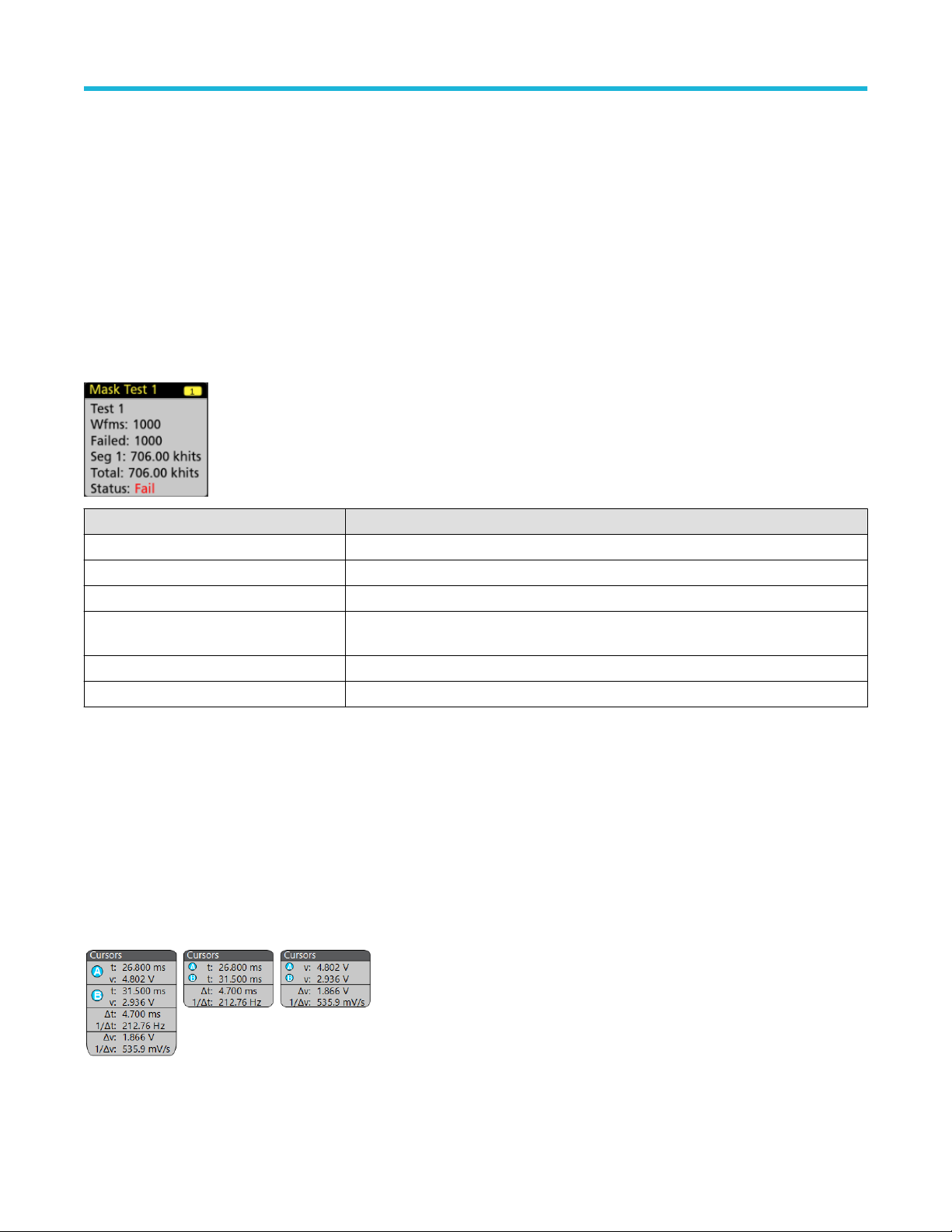
Getting acquainted with your instrument
Measurement badges are listed in the order created, starting at the top of the Results bar. Deleting a Measurement badge does not
change the order or names of the remaining badges.
You can drag Measurement badges to change their position in the Results bar and open the badge right-click menu to access a
quick-action menu.
There are two ways to delete Channel and Waveform badges.
• Right-click the badge and turn it off.
• Flick the badge off the right edge of the display to remove it from the Results bar. Flicking left from the right edge of the Results bar
recovers the badge. Badge recovery is only possible within 10 seconds of removal.
Mask Test Badge
The mask test results and measurement statistics are displayed in the Mask Test badge in the Results bar. The badge is created when the
first segment of a mask is defined.
Badge readout Description
Label A label defined in the badge configuration menu.
Wfms The total number of waveforms tested against the mask.
Failed The number of waveforms that contained one or more samples that violated the mask.
Hits (optional readout) A row is created for each segment that makes up the mask. The number displayed is the
number of times that segment has been hit.
Total The total number of hits on all segments.
Status The status of the mask test. Either Pass (green) or Fail (red) is displayed.
Double-tap a Mask Test badge to open its configuration menu to change or refine settings.
You can drag the badge to change its position in the Results bar and open the badge right-click menu to access a quick-action menu.
There are two ways to delete Channel and Waveform badges.
• Right-click the badge and turn it off.
• Flick the badge off the right edge of the display to remove it from the Results bar. Flicking left from the right edge of the Results bar
recovers the badge. Badge recovery is only possible within 10 seconds of removal.
Cursor Badges
You can display the cursor readouts in a Cursors badge in the Results bar. The badge contents depend on the cursor in use.
To create a cursor readouts badge, turn on Cursors, double-tap a cursor readout to open its configuration menu, and set the Readouts
mode to Badge.
2 Series Mixed Signal Oscilloscopes MSO22 and MSO24 Help 41
Page 42

Getting acquainted with your instrument
Note: You can only view cursor readouts in one location at a time; either on the waveform or in a Cursors badge. You cannot
move cursor readouts to a badge for Spectrum View cursors.
You can drag the badge to change its position in the Results bar and open the badge right-click menu to access a quick-action menu.
There are two ways to delete Channel and Waveform badges.
• Right-click the badge and turn it off.
• Flick the badge off the right edge of the display to remove it from the Results bar. Flicking left from the right edge of the Results bar
recovers the badge. Badge recovery is only possible within 10 seconds of removal.
Search badges
Search badges are also shown in the Results bar, below the Measurement badges. A search badge lists the search source, search type,
and the number of search event occurrences in the current acquisition. The instrument marks the waveform where those events occur with
small down-pointing triangles along the top of the waveform graticule. Double-tap a search badge to open its configuration menu to change
or refine search settings.
Search badges are created by tapping the Search button. Use the displayed configuration menu to set the search criteria.
Search badges have < (Previous) and > (Next) Navigation buttons that open the Zoom mode and center the waveform in the display
at the position of the previous or next search mark in the waveform record. Search badge Navigation buttons are only usable when the
oscilloscope is in single acquisition mode. Single-tap a badge to close the Navigation buttons.
Some searches also provide Min and Max navigation buttons that open the Zoom mode and center the waveform in the display at the
minimum or maximum value for that search event in the current acquisition.
Search badges are listed in the order created. Deleting a Search badge does not change the order or names of the remaining badges.
You can drag Search badges to change their position in the Results bar and open the badge right-click menu to access a quick-action
menu.
There are two ways to delete Channel and Waveform badges.
• Right-click the badge and turn it off.
• Flick the badge off the right edge of the display to remove it from the Results bar. Flicking left from the right edge of the Results bar
recovers the badge. Badge recovery is only possible within 10 seconds of removal.
Deleting mass Measurements/Searches badges at Once
This badge helps you to delete/remove many number measurements or searches, which are in the Results bar.
1. Select and right click on the Measurement/Search badge in the Results bar, which displays the dialog box as shown:
2 Series Mixed Signal Oscilloscopes MSO22 and MSO24 Help 42
Page 43

Getting acquainted with your instrument
Controls Description
Configure Measurement/Search Configure Measurement or Search badges
Delete Measurement/Search Deletes the selected Measurement (standard, jitter, power, DDR, etc.)/Search badge
Delete all Measurement/Search Deletes all the Measurement (standard, jitter, power, DDR, etc.)/Search badge in the
Results bar.
2. When Delete All Measurements is selected, the oscilloscope asks for the confirmation to delete all the measurements/search at a
time.
3. The dialog box provides you a checkbox that gives the choice to bypass remaining information dialogs.
• Don’t ask for remaining items: Default is unchecked. If you leave it unchecked and clear the information dialog, then the dialog
will appear again for the next measurement deletion.
• If the box is checked, it proceeds with deleting the rest of the items without bringing up the dialog box again.
Note: The dialog box appears for each set of measurements you want to delete.
Signal Clipping and Badges
Warning: Clipping is caused by excessive or dangerous voltage at the probe tip, and/or a vertical scale setting that is not
adequate to display the entire vertical range of the waveform. Excessive voltage at the probe tip can injure the operator and cause
damage to the probe and/or instrument.
This instrument shows a warning triangle symbol and the words Clipping in a Channel badge when a vertical clipping condition exists. Any
measurement badges associated with that channel also indicate a clipping condition by turning the measurement text red and listing the
type of clipping (positive or negative).
To close the clipping message, change the vertical scale to show the entire waveform, disconnect the probe tip from the excessive voltage
source, and check that you are probing the correct signal using the correct probe.
Clipping causes inaccurate amplitude-related measurement results. Clipping also causes inaccurate amplitude values in saved waveform
files. If a math waveform is clipped, it will not affect amplitude measurements on that math waveform.
System badges
System badges (in the settings bar) display the main Horizontal and Trigger settings. You cannot delete System badges.
2 Series Mixed Signal Oscilloscopes MSO22 and MSO24 Help 43
Page 44

Getting acquainted with your instrument
Double-tap a System badge to open its configuration menu.
The Horizontal badge also has Scale buttons, shown by single-tapping the badge. Use the Horizontal Scale buttons to increase or
decrease the horizontal time setting.
Common badge actions
Action Result Example
Single tap Immediate access controls (Scale,
Navigation).
Double tap Configuration menu with access to all
settings for the badge.
Touch and hold Right-click menu with single tap
access to common actions. Typical
actions include turning off a channel
and deleting a measurement or
search badge.
Flick Flick the badge off the bottom edge of the display to remove it from the Settings bar.
Flick the badge off the right edge of the display to remove it from the Results bar.
Flick from the right or bottom edge to recover a removed badge. This action is only possible within 10 seconds of
badge removal.
Badge selection status
The appearance of a badge indicates its selection status (selected or unselected), or if a measurement needs to be deleted to close a
channel or waveform badge.
2 Series Mixed Signal Oscilloscopes MSO22 and MSO24 Help 44
Page 45

Getting acquainted with your instrument
Badge type Selected Unselected
Turned off or in use
1
Channel or
Waveform
Measurement N/A
Moving waveform and measurement badges
You can move waveform and measurement badges within their display bars to meet your measurement needs. Simply touch and drag the
badge to a new position.
Moving waveform badges in the Settings Bar
• A waveform badge can only be moved within the Settings Bar.
• Dragging a waveform badge to a new location selects that waveform.
• Dragging a badge to a new location causes the non-selected badges to move slightly to create the position at which to insert the
badge.
• To move a badge to a position that is off screen of the displayed bar badges (scroll buttons are present), drag the badge that you're
moving onto one of the scroll buttons. The badges that are off screen shift onscreen one at a time until you move the badge off of the
scroll button and position it in the displayed badges.
• Changing the order of waveform badges or badge groups also changes the order of displayed waveforms in the Waveform view. The
order of badges or badge groups (left to right) in the Settings bar determines the order of slices in the display (top to bottom).
• Once you have moved any waveform badge (Channel, Math, Ref, Bus) on the Settings bar to a new position, adding a new badge
adds that badge to the right of the existing badges. This differs from the default badge addition action, which listed badges together by
category (Channels, Math, Ref, Bus) and arranged the badges in numerical order within each badge category. To restore the default
badge addition method, tap File > Default Setup and add the waveform badges back onto the Settings bar.
• Changing the order of bus waveform badges changes the order of the tabs in a bus decode Results table.
Moving badges in the measurement Results Bar
• A Measurement or Search badge can only be moved within the Results Bar.
• Dragging a badge to a new location causes the non-selected badges to move to create the position at which to insert the badge.
• Once you have moved any Results badge to a new position, adding a new Measurement or Search badge adds that badge to the
bottom of the Results bar badges.
• To move a badge to a position that is off screen of the displayed bar badges (scroll buttons are present), drag the badge that you're
moving onto one of the scroll buttons. The badges that are off screen shift onscreen one at a time until you move the badge off of the
scroll button and position it in the displayed badges.
• Changing the order of Measurement badges in the Results bar changes the order of measurements shown in a Results table.
• Changing the order of Search badges in the Results Bar changes the order of the tabs shown in a Search Results table.
1
A dimmed Channel badge means the screen waveform is turned off (but not deleted). A dimmed Waveform badge means that the waveform display is turned off, or it
is being used as a source by a measurement and cannot be deleted until the measurement is deleted.
2 Series Mixed Signal Oscilloscopes MSO22 and MSO24 Help 45
Page 46

Getting acquainted with your instrument
Badge grouping
You can group signal badges in the Settings bar to display multiple waveforms in a single slice.
Group signal badges in the Settings bar
You can group signal badges in any combination of channel, waveform, math, reference and bus badges to display related waveforms in
the same display slice. Use this feature to group related signals for easier visual comparisons.
To group one or more signal badges, drag a badge onto another badge until the background badge turns red, then release. Repeat to add
other badges to a group. Each group is shown in its own slice as a set of overlaid waveforms.
Badge group characteristics
• Badges in a group are listed left to right in the order they were added to the group.
• The badge group color is the color of the last selected badge in the group.
• Use standard touch and menu interactions to select and change individual badge settings.
• You can drag and move badge groups the same way as individual badges.
• The order of badges or badge groups (left to right) determines the order of slices in the display (top to bottom).
• To ungroup a single badge, drag it vertically and release. You can also ungroup a single badge by touching and holding a badge in the
group to open its right-click menu, and select Ungroup Badge(x) to ungroup the selected badge.
• To ungroup the entire group, touch and hold any badge in the group to open its right-click menu. Select to ungroup the selected badge
or ungroup all of the badges.
Badge group caveats
• You cannot drag badges within a group to change their order.
• You cannot add one badge group to another.
• You cannot drag a badge group onto an individual badge to group those badges.
Configuration menus
Configuration menus let you quickly set the parameters for channels, system settings (Horizontal, Trigger), measurements, cursor
readouts, Waveform and Plot views, callout text, and so on.
Double-tap an item (badge, Waveform View or Plot View, cursor readouts, callout text, and so on) to open its configuration menu. For
example, double-tap a Channel badge in the Settings Bar to open its configuration menu.
2 Series Mixed Signal Oscilloscopes MSO22 and MSO24 Help 46
Page 47

Getting acquainted with your instrument
Selections or values that you enter take effect immediately. Menu contents are dynamic, and can change depending on your selections,
instrument options, or attached probes.
Related settings are grouped into 'panels'. Tap the panel name to show those settings. Changes to panel settings can change the values
and/or fields shown in that panel and other panels.
Tap anywhere outside a configuration menu to close it.
To open Help content for a configuration menu, tap the question mark icon in the upper right corner of the menu.
Zoom user interface
Use the zoom tools to magnify waveforms to view signal details.
1. The Zoom Overview shows the entire waveform record. All waveforms are shown in Overlay mode in the Zoom Overview area.
Using pinch and expand gestures on the Zoom Overview waveforms changes the horizontal time base settings.
Note:
2. The Zoom Box shows the area of the Zoom Overview to display in the Zoom View (see 5). You can touch and drag the box to move
the area to view.
Moving the Zoom Box, or changing its position, does not change the horizontal time base settings.
Note:
3. The Zoom icon (in the upper right corner of the Waveform View) switches zoom mode on and off.
2 Series Mixed Signal Oscilloscopes MSO22 and MSO24 Help 47
Page 48

Getting acquainted with your instrument
4. A zoom box lets you quickly draw a box around an area of interest in the Waveform or Zoom Overview. Drawing a box immediately
puts the oscilloscope into zoom mode. To draw a zoom box, tap the DRAW-A-BOX button (while in Zoom mode), then touch and drag
on the waveform to draw a box waveform. You can continue to draw zoom boxes until you single tap anywhere on the screen or open a
menu.
To toggle between Zoom mode and Mask mode, double-tap the DRAW-A-BOX button and select one of the two options. Search for
the Mask Testing topics in the oscilloscope Help for more information.
5. The Zoom View shows the zoomed waveforms, as marked by the Zoom Box, in the Zoom Waveform Record View. Use pinch and/or
drag options in the zoom view to change the zoomed area of interest.
Note: Pinch, expand, and drag gestures in the Zoom View only change zoom magnification settings and Zoom Box position.
6. Use the Zoom Title Bar controls to adjust the vertical and horizontal size of the zoom area. Click or tap the + or - buttons or use the A
and B multipurpose knobs.
In a waveform view, if both Cursor and Zoom are turned on, use the Zoom Box and Cursors button to change the multipurpose knob
functionality. Tap the Zoom Title Bar to assign the knobs to adjust the zoom or tap the Cursors button to assign knobs to adjust the
cursors.
Double tap the Horizontal Zoom Position or Horizontal Zoom Scale fields to enter a value using a numerical keypad.
To exit the zoom display mode, tap the Zoom icon in the corner of display or tap the X in the Zoom Title Bar.
Math-FFT or XY plot view zoom
Use the A and B multipurpose knobs to adjust the zoom for Math-FFT or XY plot view.
In a Math-FFT or XY plot view, if A and B multipurpose knobs are assigned to Zoom, the zoom box is highlighted and the multipurpose
knobs within the Zoom Box are enabled.
If both Cursors and Zoom are turned on in Math-FFT or XY Plot view, use the Zoom Box and Cursors button to change the multipurpose
knob functionality. Tap the Zoom Box to assign the knobs to adjust zoom or tap the Cursors button to assign knobs to adjust the cursors .
To exit the zoom display mode, tap the Zoom icon in the corner of view or tap the X in the Math-FFT view or XY plot view.
2 Series Mixed Signal Oscilloscopes MSO22 and MSO24 Help 48
Page 49

Getting acquainted with your instrument
Using the touch screen interface for common tasks
Use standard touch screen actions, similar to those found on smart phones and tablets, to interact with most screen objects. You can also
use a mouse to interact with the UI. The equivalent mouse operation is shown for each touch operation.
The oscilloscope has a user interface tutorial. Tap Help > User Interface Tutorial to quickly learn the fundamental touch operations.
Table 3: Common touchscreen UI tasks with mouse equivalents
Task Touchscreen UI action Mouse action
Add a channel, math, reference,
or bus waveform to the screen.
Select a channel, math,
reference, or bus waveform to
make it active
Tap an inactive channel button, Add New Math,
Add New Reference, or Add New Bus button.
Stacked or Overlay mode: Tap the Channel or
Waveform badge.
Stacked mode: Tap the channel, math, reference,
or bus waveform slice or handle.
Click an inactive channel button, Add New Math,
Add New Reference, or Add New Bus button.
Stacked or Overlay mode: Left-click the Channel or
Waveform badge.
Stacked mode: Left-click the channel, math,
reference, or bus waveform slice or handle.
Overlay mode: Tap the channel or waveform
handle.
Display scale or navigation
Tap the badge. Click the badge.
buttons on a badge
(waveform, measurement2,
search, horizontal).
Open a configuration menu on
Double-tap the badge, view, or other object. Double-click the badge, view, or other object.
any item (all badges, views,
cursor readouts, labels, and so
on).
Open a right-click menu
(badges, views).
Close a configuration menu.
Touch and hold on the badge, Waveform View, Plot
view, or other screen item until a menu opens.
3
Tap anywhere outside the menu or dialog. Click anywhere outside the menu or dialog.
Move a menu. Touch and hold the menu title bar or a blank area
in the menu, then drag the menu to new position.
Move a callout.
4
Touch and hold on a callout and quickly 5 start to
drag, then move to new position.
Change horizontal or vertical
settings directly on a waveform.
Vertical changes only apply
to the selected channel or
Tap a badge and use the Scale buttons.
Touch and hold two fingertips on the waveform
view, move them together or apart vertically or
horizontally, lift from screen; repeat.
waveform; horizontal changes
apply to all channels and
waveforms.
Overlay mode: Left-click the channel or waveform
handle.
Right-click the object.
Click and hold the right mouse button on title or
blank area, drag to new position.
Click and hold the right mouse button on the
callout and quickly start to drag, then move to the
new position.
Left-click a channel, waveform, or Horizontal
badge and click on the Scale buttons.
Table continued…
2
Not all measurement or search badges display navigation buttons.
3
Some dialog boxes will not close until you click an OK, Close, or other button in the dialog.
4
Callouts are screen objects and are not associated with any particular waveform channel or slice.
5
Start to move the callout as soon as selected (highlighted), otherwise the UI opens the right-click menu.
2 Series Mixed Signal Oscilloscopes MSO22 and MSO24 Help 49
Page 50

Getting acquainted with your instrument
Task Touchscreen UI action Mouse action
Increase or decrease the zoom
area (while in Zoom mode)
Touch and hold two fingertips on the waveform
view, move them together or apart vertically or
horizontally, lift from screen; repeat.
Click the + or - buttons on the Zoom Title bar.
Click the Draw-a-Box button, draw a box around
the waveform area of interest.
Quickly scroll or pan a waveform
or list.
Close or open the Results Bar
to increase the Waveform View
area.
Change the position of badges
in the Settings Bar or Results
Bar.
Touch and drag in the waveform or list. Click and drag in the waveform or list.
Tap on the Results Bar Handle (three vertical dots
in border) or anywhere in the border between the
Waveform View and the Results Bar.
Touch and drag the badge to a new position in the
same bar.
Click the Results Bar Handle (three vertical dots
in border) or anywhere in the border between the
Waveform View and the Results Bar.
Click and drag the Results Bar divider.
Click and drag the badge to a new position in the
same bar.
Accessing application help
Use the instrument online help to quickly get information about a function or assistance in performing a task.
Using context-sensitive help
To open help on a particular menu or item, tap the Help button (question mark symbol) in the title bar. The browser opens with content
relevant to the menu or item.
Navigating the online help
Select Help > Help. The Help Browser is similar in look and feel to PC-based Help tools.
The Help tool does not have a virtual keyboard. Connect a keyboard to your instrument to enter text in the search fields of
Note:
the Search or Index tabs.
From the help browser, select one of the following tabs:
• Contents Tab. Click any entry to display information on the subject.
• Search Tab. Type in the keyword you are looking for; then click List Topics. Every topic that contains the keyword will be displayed.
Select a topic, and then click Display to open the topic.
Other help features
Zoom on help text. Use the magnifying glass icons to zoom in or out of the help text.
2 Series Mixed Signal Oscilloscopes MSO22 and MSO24 Help 50
Page 51

Configure the instrument
Configure the instrument
Configure the instrument to your preferred settings.
Download and install the latest instrument firmware
Installing the latest firmware helps ensure that your instrument has the latest features and is taking the most accurate measurements.
Before you begin
Save any important on-instrument files such as waveforms, screen captures, and setups to a USB drive or network. The installation
process does not remove user-created files, but it is recommended to back up important files before an update.
Determine the current version of firmware installed on the instrument using the Help > About menu.
Procedure
To download the instrument firmware and install onto an instrument:
1. Open up a Web browser on a PC and go to www.tek.com/product-support
2. Enter the instrument model number in the search field and click Go.
3. Scroll down the screen and click the Software tab.
4. If the listed available firmware version (Windows or non-Windows) is newer than what is on your instrument, select and download that
file to your PC.
5. Copy the downloaded firmware file to a USB drive.
6. Insert the USB drive with the firmware file into one of the USB ports on the instrument.
7. Power on the instrument.
For the battery operated instrument, connect the power cord and keep it connected during the upgrade of an instrument firmware.
8. Follow on-screen instructions.
The instrument will take a few minutes to install the new firmware. Do not remove the USB flash drive or power off the instrument
during this time.
What to do next
To confirm the firmware update, locate the version number found in the About window under the Help menu. Confirm that the instrument
firmware version number matches the firmware version number that you just installed.
Set the time zone and clock readout format
Set the time zone to your region so that saved files are marked with the correct date and time information. You can also set the time format
(12 or 24 hour clock).
Procedure
1. Double-tap the Date/Time badge (bottom-right of screen) to open the configuration menu.
2. To turn off showing the date and time on the screen, tap Display button to Off.
2 Series Mixed Signal Oscilloscopes MSO22 and MSO24 Help 51
Page 52

Configure the instrument
To turn on date/time display again, double-tap in the blank area where the date/time badge was displayed to open the configuration
menu, and set the Display button to On.
3. Select a time format (12 Hour or 24 Hour).
4. Tap the Time Zone field and select the time zone that applies to your location.
5. Tap anywhere outside of the menu to close it.
Functional check
Use this procedure to quickly verify that the oscilloscope can display a waveform and take a measurement.
1. Power on the oscilloscope.
2. Tap Utility > Self test. Check that all tests listed show Pass.
3. Connect an analog probe to the Channel 1 connector.
4. Connect the oscilloscope tip and ground lead to the probe compensation connectors.
5. Push the Autoset button. You should see a square wave in the display (approximately 5 V
6. Tap the Measure button.
7. Tap the Time Measurements panel in the Add Measurements configuration menu.
8. Double-tap the Frequency button to add the frequency measurement to the Results bar.
9. Check that the Frequency measurement reads 1 kHz.
10. Repeat these steps to check the other channels on the oscilloscope. Make sure that you set the source in the Add Measurement
configuration menu to use the correct channel before adding the Frequency measurement.
P-P
).
Run Signal Path Compensation (SPC)
Run SPC when you first receive an instrument, and at regular intervals, for best measurement accuracy. You should run SPC whenever
the ambient (room) temperature has changed by more than 5 °C (9 °F), or once a week if you use vertical scale settings of 5 mV per
division or less.
About this task
Signal Path Compensation (SPC) corrects for DC level inaccuracies in the internal signal path, caused by temperature variations and/or
long-term signal path drift. Failure to run SPC on a regular basis may result in the instrument not meeting warranted performance levels at
low volts per division settings.
Before you begin
Disconnect all probes and cables from the front-panel channel inputs and rear-panel signal connectors.
Procedure
1. Power on and warm up the instrument for at least 20 minutes.
2. Tap Utility > Calibration.
3. Tap Run SPC. The SPC Status readout shows Running while SPC is running. SPC can take three minutes approximately per channel
to run, so wait until the SPC Status message changes to Pass before reconnecting probes and using the instrument.
CAUTION: You can abort the SPC calibration by tapping Abort SPC. This may leave some channels uncompensated,
resulting in possible inaccurate measurements. If you do abort the SPC, make sure to run the SPC procedure completely
before using the instrument to take measurements.
4. Close the Calibration configuration dialog when SPC has completed.
If the SPC fails, write down any error message text. Make sure that all probes and cables are disconnected and run the SPC again. If
the SPC still fails, contact Tektronix Customer Support.
2 Series Mixed Signal Oscilloscopes MSO22 and MSO24 Help 52
Page 53

Configure the instrument
Compensate the TPP Series probes
Probe compensation adjusts the high frequency response of a probe for best waveform capture and measurement accuracy.
Before you begin
The oscilloscope must be powered on for at least 20 minutes before compensating a probe.
Procedure
Use this procedure to compensate supported TPP-family probes that show a Default status when connected to the oscilloscope.
Compensate passive probes
Use this procedure to optimize gain and offset accuracy at the probe tip. Allow the instrument to warm up before performing this procedure.
Perform the low frequency probe compensation for passive probes.
Note: The probe compensation procedure is not recommended for the P5050 passive probes. These probes have little gain or
offset errors. However, you should perform this procedure for other passive probes.
Complete the following steps:
1. If you have not already done so, connect the probe to the instrument.
2. Connect the probe to probe compensation (Fast Edge on some models) terminals as shown. Connect only one probe at a time.
3. Select Probe Cal from the Vertical menu to open the Probe Compensation control window.
4. Select the channel to which the probe is attached.
5. Click Compensate Probe to begin the procedure. The Probe Status indicator changes to Pass when the procedure is complete. If the
procedure does not pass, contact your local Tektronix service personnel.
6. Remove the connections from the terminals.
Connect to a network (LAN)
Connecting to a network allows you to remotely access the instrument.
Work with your network administrator to obtain the required information to connect to your network (IP address, Gateway IP address,
Subnet Mask, DNS IP address, and so on).
1. Connect a CAT5 cable from the instrument LAN connector to your network.
2. Select Utility > I/O on the menu bar to open the I/O configuration menu.
3. Obtain or enter the network address information:
• If your network is DHCP-enabled, and the IP address field does not already show an address, tap Auto to obtain the IP address
information from the network. DHCP mode is the default mode.
• If your network is not DHCP-enabled, or you need a permanent (non-changing) IP address for this instrument, tap Manual and
enter the IP address and other values provided by your IT or system administrator resource.
4. Tap Test Connection to verify that the network connection is working. The LAN Status icon turns green when the instrument
successfully connects to your network. If you have problems connecting to your network, contact your system administration resource
for help.
2 Series Mixed Signal Oscilloscopes MSO22 and MSO24 Help 53
Page 54

Configure the instrument
Mount a network drive from a standard instrument
Use this procedure to mount (map) a network Linux mount point shared directory on a standard (non Windows OS) instrument.
Prerequisites: The oscilloscope must be connected to a network that has access to the directories to mount or unmount. See Connect to
a network (LAN) on page 53.
To mount a Linux network drive on the oscilloscope, the network Linux mount point (drive, host) that you want to mount must be exported.
If the mount point is not exported, work with your organization's IT resource to get that location exported and accessible to your network.
To mount a network drive on your standard oscilloscope:
1. Tap File > File Utilities.
2. Tap Mount to open the Mount Drive menu.
3. Select Network in the Drive Type.
4. Select the drive letter to assign to the network drive from the Drive Letter list.
5. Tap Name or IP to specify how you will enter the host name (server) of the network mount location or PC.
6. Enter the network host name or IP address of the Linux mount point or Windows PC or server in the Server Name or Server IP
Address field. Example: ACME-PC0205
7. Enter the path to the location of the mount point or shared directory of the server in the Path field.
Linux example: /opt/testing/batch1 (Linux requires forward slashes in path definitions. Linux assumes that the path starts at the root
directory.
8. If access to this network location is controlled, enter the required information in the User Name and Password fields.
9. Tap OK. The oscilloscope mounts the drive and adds the specified drive letter to the Drive column in the File Utilities menu.
The oscilloscope displays an error message if it cannot mount the drive. Work with your organization's IT resource to verify that the
access information is correct and to resolve the network access problems.
CAUTION:
The Linux ScopeApp does not support SMB version 1.0 for CIFS network mounts.
Mount a TekDrive on the instrument
You can access, interact with, and download your mission-critical data securely from anywhere in the world. TekDrive is the storage facility
given to you from Tektronix when you have purchased any of our 2 Series MSO oscilloscope. The cloud allows you the facility to upload
and download the files from anywhere and everywhere with easy access to the data anytime. The data is stored with high security and
a sophisticated infrastructure to ensure confidentiality, integrity, and availability of your data. With TekDrive, anyone in your company can
view and interact with shared files uploaded to your account. Use the below procedure to mount (map) a TekDrive on a instrument.
Before you begin
The oscilloscope must have internet connectivity access.
Browse to drive.tekcloud.com, register, and create a new account.
• The TekDrive mount feature is supported on 2 Series MSO oscilloscopes.
• The maximum upload file size limit to TekDrive is restricted to 25 GB.
• When the TekDrive is enabled, copy/paste for the files/folders in the TekDrive menu are disabled.
• In some scenarios, recalling the files from the TekDrive is not supported hence you will not see it listed in the file chooser, but you can
continue recalling the file through USB/Network or Local drives.
For example, Math Filter files cannot be recalled/applied from math advanced menu if it's stored in the TekDrives.
• When a TekDrive is unmounted or auto-disconnected, the waveform files activated from it would continue to work until you recall the
defaults, or run TekSecure®, or change the reference waveform file.
2 Series Mixed Signal Oscilloscopes MSO22 and MSO24 Help 54
Page 55

Configure the instrument
About this task
To mount a TekDrive on your oscilloscope:
1. Tap File > File Utilities.
2. Tap Mount to open the Mount Drive menu.
3. Select TekDrive in the Drive Type using the toggle switch.
4. Enter the Drive Name.
5. Select the required Auto Disconnect option.
6. Tap Connect to TekDrive which displays the window with the QR/Numeric code for the TekDrive activation.
7. Browse to drive.tekcloud.com/activate to login using the credentials and enter the numeric code displayed on the mount drive window
in the oscilloscope application. Register and create a new account if you are a new user.
8. The activation successful message is displayed on the oscilloscope application window.
9. After the successful activation, click OK, mount Tekdrive to finish the TekDrive mounting on the oscilloscope.
10. Once the specified TekDrive has been successfully connected to oscilloscope, the drive appears in all file browsing dialog windows.
Unmount a network drive from a standard instrument
Use this procedure to unmount (remove, disconnect) a network Linux mount point from a standard (non-Windows 10) instrument.
To unmount a network drive from your instrument:
1. Tap File > File Utilities.
2. Select the drive to unmount in the Drive column.
3. Tap Unmount. The instrument immediately unmounts the drive and removes it from the Drive column.
Unmount a TekDrive from the instrument
Use this procedure to unmount (remove, disconnect) a TekDrive from a instrument.
About this task
To unmount a TekDrive from your instrument
1. Tap File > File Utilities.
2. Select the TekDrive to unmount in the Drive column.
3. Tap Unmount. The instrument immediately unmounts the drive and removes it from the Drive column.
Connect the oscilloscope to a PC using a USB cable
Use a USB cable to connect the oscilloscope directly to a PC for remote instrument control.
1. On the oscilloscope, select Utility > I/O from the menu bar.
2. Tap USB Device Port Settings.
3. Confirm that the USB Device Port control is On (default setting).
4. Connect a USB cable from the PC to the USB Device port on the side of the instrument.
5. If using the USB connection to remotely control the oscilloscope using GPIB commands, set the GPIB Talk/Listen Address for your
configuration (0 - 30).
2 Series Mixed Signal Oscilloscopes MSO22 and MSO24 Help 55
Page 56

Configure the instrument
Deskew analog input channels - quick visual method
Use the following procedure to visually align waveform edges to compensate for timing differences between probes.
Critical Time measurements on multiple channels require that all probes be adjusted, or deskewed, to compensate for signal timing
differences between probes. This procedure uses displayed waveform edges to quickly minimize deskew between probes.
Note: Once probes have been deskewed for a particular channel, you should only use the probes on the channels for which they
were deskewed, when taking critical Time measurements.
1. Connect all probes that you want to deskew.
2. Connect up to four probe tips and ground leads to the Probe Compensation connector (maximum of four channels at a time).
3. Turn on (display on screen) the connected channels that you want to deskew.
4. Double-tap in the Waveform view and set Waveform Mode to Overlay.
5. Push the Autoset button.
6. Adjust the vertical Scale and Position controls for each channel so that the signals overlap and are centered on the display.
7. Adjust the horizontal Scale so that the differences in the channel delays are clearly visible.
8. Determine the channel you want to use as your reference.
9. Double-tap the Channel badge of a channel other than the reference channel and tap the Other panel.
10. Tap the Deskew field and use the multipurpose knob to align this channel with the reference channel waveform such that the
waveforms cross the trigger point at the same time. For fine adjust, double-tap the Deskew field to open a number pad.
11. Repeat steps 9 and 10 for each additional channel you want to deskew.
12. To deskew additional channels:
a. Disconnect all probe tips except the reference probe from the Probe Compensation connections.
b. Connect up to three probe tips and ground leads to the Probe Compensation connector (maximum of four channels at a time).
c. Repeat steps 3 through 12 for the additional channels to deskew.
Deskew analog input channels - measurement method
Use the following procedure to more accurately minimize timing differences between probes.
Critical Time measurements on multiple channels require that all probes be adjusted, or deskewed, to compensate for signal timing
differences between probes. This procedure uses a Delay measurement to adjust a probe's deskew setting.
Once probes have been deskewed for a particular channel, you should only use the probes on the channels for which they
Note:
were deskewed, when taking critical Time measurements.
1. Connect all probes that you want to deskew to the oscilloscope.
2. Connect up to four probe tips and ground leads to the Probe Compensation connector (maximum of four channels at a time).
3. Turn on all the channels of the first four channels that you want to deskew.
4. Push the Autoset button.
5. Change the vertical Scale of all active channels to 500 mV/div and adjust the vertical Position so that the waveforms are centered in
their respective slices.
6. Determine the channel you want to use as your reference.
7. Tap the Measure button and tap the Time Measurements panel.
8. Select the Delay measurement and set your chosen reference channel as Source 1 and your channel being deskewed as Source 2,
then tap the Add button.
9. Double-tap the Channel badge of the channel being deskewed (Source 2) and tap the Other panel.
10. Tap the Deskew field and use the multipurpose knob to align this channel with the reference waveform such that the measured delay
between channels becomes a minimum. For fine adjust, double-tap the Deskew field to open a number pad.
2 Series Mixed Signal Oscilloscopes MSO22 and MSO24 Help 56
Page 57

Configure the instrument
11. Double-tap the Delay measurement badge and set the Source 2 channel to the next channel to deskew.
12. Repeat steps 9 through 11 for each additional channel you want to deskew in the first set of four.
13. To deskew additional channels:
a. Disconnect all probe tips except the reference probe from the Probe Compensation connections.
b. Connect up to three probe tips and ground leads to the Probe Compensation connector (maximum of four channels at a time).
c. Repeat steps 3 through 13 for the additional channels to deskew.
Connect a keyboard or mouse
The instrument supports most standard USB-connected keyboards and mice, and wireless-connected keyboards and mice (using a
USB-connected dongle).
Connect a keyboard and/or mouse by connecting their USB cable, or USB dongle, into any available USB Host port. The keyboard or
mouse should work immediately. If it does not, try the following:
1. Remove and reinsert the USB cable or dongle in the same port.
2. Insert the USB cable or dongle into a different USB port.
ESD Prevention Guidelines
Electrostatic discharge (ESD) can damage oscilloscope and some probe inputs. This topic discusses how to avoid this type of damage.
Electrostatic discharge (ESD) is a concern when handling any electronic equipment. The instrument is designed with robust ESD
protection, however it is still possible that large discharges of static electricity directly into the signal input may damage the instrument. Use
the following techniques to prevent electrostatic discharge from damaging the instrument.
• Discharge the static voltage from your body by wearing a grounded antistatic wrist strap while connecting and disconnecting cables,
probes, and adapters. The instrument provides a ground connection to which to attach a wrist strap (on the Probe Comp ground
connector).
• A cable that is left unconnected on a bench can develop a large static charge. Discharge the static voltage from all cables before
connecting them to the instrument or device under test by momentarily grounding the center conductor of the cable, or by connecting a
50 Ω termination to one end, before attaching the cable to the instrument.
• Before you apply power, connect the instrument to an electrically-neutral reference point, such as earth ground. To do this, plug the
three-pronged power cord into an outlet grounded to earth ground. Grounding the oscilloscope is necessary to ensure safety and to
take accurate measurements.
• If you are working with static sensitive components, ground yourself. Static electricity that builds up on your body can damage
static-sensitive components. Wear a wrist strap to safely send static charges on your body to earth ground.
• The oscilloscope must share the same ground as any circuits that you plan to test.
2 Series Mixed Signal Oscilloscopes MSO22 and MSO24 Help 57
Page 58

Analog channel operating basics
Analog channel operating basics
Acquiring a signal
After acquiring a signal you can take measurements and plot the results.
Use the following procedure to set the scale and position parameters for analog signal acquisition.
1. Press the Default Setup button.
2. Connect the probe output to the desired oscilloscope channel, and connect the probe input to the input signal source using proper
probing/connecting techniques.
Note: Some probes automatically set their termination and other values.
3. Tap the channel button to add the channel waveform to the waveform view and add a channel badge to the setting bar. A channel
button lights when its channel is on.
4. Double-tap the channel badge to open the channel Vertical Settings menu. To change the input coupling, select the appropriate
coupling button.
• Select DC to couple both the AC and DC components of an input signal.
• Select AC to couple only the AC components of an input signal.
5. Use the Vertical knobs to scale and position the waveform vertically on the screen. The Knobs should be highlighted with the active
channel's color. Dragging the waveform handle also positions the waveform.
6. Use the Vertical Settings menu to change the offset. Tap Offset, and then use a multipurpose knob to adjust the offset.
7. Use the Horizontal knobs to scale and position the waveform horizontally on the screen and to set the record length. Dragging the
reference icon also positions the waveform.
8. Use the Horizontal menu to set the record length and sample rate (when in Manual mode).
9. You may attempt to stabilize the display by pressing the trigger Level knob to set the trigger level to 50%. The 50% level is calculated
as the midpoint between the highest and lowest samples of the acquired waveform. If your signal is periodic you should see a stable,
triggered signal. This method will not work as well with random signals.
Autoset to quickly display a waveform
The Autoset function analyzes the signal characteristics and changes the instrument Horizontal, Vertical, and Trigger settings to
automatically display a triggered waveform. You can then make further changes to trigger and horizontal settings to view the waveform
point of interest.
1. Connect the probe with the signal of interest to an available channel.
2. Double-tap the Trigger badge and set the trigger source to that of the signal of interest.
3. Connect any other associated signal(s) to available channel input(s).
4. Add the channel waveforms to the Waveform view. See Add a channel waveform to the display on page 62.
5. Tap File > Autoset or push the front-panel Autoset button. When using the Stacked Display mode, the instrument analyzes the signal
characteristics of the trigger source channel (analog) and adjusts the horizontal, vertical, and trigger settings accordingly to display a
triggered waveform for that channel. The Vertical scale is adjusted in each waveform slice of all active waveforms to maximize ADC
utilization.
2 Series Mixed Signal Oscilloscopes MSO22 and MSO24 Help 58
Page 59

Analog channel operating basics
When using the Overlay Display mode, the instrument adjusts the horizontal and trigger settings of the trigger source channel to
display a triggered waveform for that channel. Vertical scale and position adjustments for all active channels in Overlay Display mode
are controlled by the Autoset in Overlay Display Mode Optimizes selection in the Autoset panel of the User Preferences menu. If
the selection is Visibility, Autoset vertically scales and positions all active channel waveforms such that they are uniformly spaced on
screen. If the selection is Resolution, Autoset vertically scales and positions all active channel waveforms such that they each use as
much of the ADC's range as possible.
You can set which parameters the instrument can adjust when running an Autoset. Access the Autoset panel in Utility >
Note:
User Preferences > Autoset.
Autoset guidelines
• Autoset displays three or four cycles (depending on the detected signal) with the trigger level near the midlevel of the signal.
• The trigger is set to type Edge, rising slope, DC coupling.
• If no channels are displayed before pushing Autoset, the oscilloscope adds Ch 1 to the Waveform view whether it has a signal or not.
• Autoset ignores math, reference, and bus waveforms.
• A channel or waveform with a frequency less than 40 Hz is classified as no signal.
Set Horizontal parameters
Use this procedure to set the horizontal time base parameters such as mode, minimum sample rate, horizontal scale, delay, and trigger
delay time (relative to the center of the waveform record.
1. Double-tap the Horizontal badge on the Settings bar to open the Horizontal configuration menu.
2 Series Mixed Signal Oscilloscopes MSO22 and MSO24 Help 59
Page 60

Analog channel operating basics
2. Use the menu selections to set horizontal parameters.
3. Tap the Help icon on the menu title for more information on these settings.
How to trigger on a signal
Use this procedure to open the Trigger menu to select and configure the trigger event type and conditions.
1. Double-tap the Trigger badge on the Settings bar to open the Trigger configuration menu.
2. Select a trigger from the Trigger Type list. The trigger type sets what fields are available in the menu and also updates the illustration
to show a graphic of the trigger type.
To trigger on a bus, you must first add the bus to the Waveform view. See Add a math, reference, or bus waveform on page 63
Triggering on buses other than Parallel requires purchasing and installing serial trigger and analysis options.
Note:
3. Select the other fields and panels to refine the trigger conditions. The menu fields and trigger graphic updates as you make changes to
the trigger settings. Displayed fields depend on the selected trigger type. Selection changes take effect immediately.
2 Series Mixed Signal Oscilloscopes MSO22 and MSO24 Help 60
Page 61

Analog channel operating basics
4. Tap the Help icon on the menu title for more information on these settings.
5. Tap outside the menu to close the menu.
Set the acquisition mode
Use this procedure to set the method the instrument uses to acquire and display the signal.
1. Double-tap the Acquisition badge on the Settings bar to open the Acquisition configuration menu.
2. Select the acquisition method from the Acquisition Mode list. Set any other parameters associated with the selected acquisition type.
3. Tap the Help icon on the menu title for more information on these settings.
4. Tap outside the menu to close the menu.
Start and stop an acquisition
Acquisition controls the start and stop of waveform acquisition.
1. To start an acquisition, double-tap the Horizontal configuration menu, tap the Acquisition Settings on the Settings bar. Tap Run/Stop
in the Acquisition configuration menu.
2. Tap the Stopped button on the setting bar to run the acquisition again. You can also push the Run/Stop button on the front panel.
3. To stop an acquisition, tap Run/Stop again or push the Run/Stop button. Tap the Running button on the setting bar to stop the
acquisition.
4. To take a single acquisition, double-tap the Horizontal configuration menu, tap the Acquisition Settings on the Settings bar.
5. Tap Single/Seq in the Acquisition configuration menu, or push the Single/Seq button on the front panel.
6. The color of the Run/Stop and Single/Seq buttons on the front panel indicate the acquisition status (green = acquiring, red = stopped).
7. To clear the current acquisition data from waveform memory, double-tap the Acquisition badge and tap Clear in the Acquisition
configuration menu, or push the Clear button on the front panel.
2 Series Mixed Signal Oscilloscopes MSO22 and MSO24 Help 61
Page 62

Add a channel waveform to the display
Use this procedure to add a channel signal to the Waveform View.
1. Connect signal(s) to the channel input(s).
2. Tap an Inactive Channel button (in the Settings bar) of a connected channel.
The selected channel is added to the Waveform View and a Channel badge is added to the Settings bar.
Analog channel operating basics
3. Continue tapping Inactive Channel buttons to add more channels (analog). Channels are displayed from lowest-numbered channel at
the top, to highest-numbered channel at the bottom of the view, regardless of the order they were added (in stacked mode).
4. Double-tap a channel badge to open that channel's configuration menu to check or change settings.
2 Series Mixed Signal Oscilloscopes MSO22 and MSO24 Help 62
Page 63

Analog channel operating basics
Configure channel or waveform settings
Use the channel and waveform configuration menus to set parameters such as vertical scale and offset, coupling, bandwidth, probe
settings, deskew values, external attenuation values, and other settings.
Before you begin
Prerequisite: There is a channel or waveform badge in the Settings bar.
Procedure
1. Double-tap a Channel or Waveform badge to open a configuration menu for that item.
For example, in a Channel menu, use the Vertical Settings panel to set basic probe parameters such as vertical scale and position,
offset, coupling, termination, and bandwidth limit. Available settings depend on the probe.
2. Tap the Probe Setup panel to confirm probe settings and run configuration or compensation on supported probes.
3. Tap the Help icon on the menu title to open the help topic for more information.
4. Tap outside the menu to close the menu.
Add a math, reference, or bus waveform
Math waveforms let you create new waveforms based on operations between two or more waveforms or by applying equations to
waveform data. A reference waveform is a static waveform record displayed for comparison. Bus waveforms let you view and analyze
serial or parallel data.
There is no set limit to the number of Math, Reference, or Bus waveforms you can add to the Waveform View, other than system physical
memory constraints.
1. Tap the Math Ref Bus > Add New Math, Add New Ref, or Add New Bus button in the Settings bar.
2 Series Mixed Signal Oscilloscopes MSO22 and MSO24 Help 63
Page 64

Analog channel operating basics
2. The instrument adds the waveform to the Waveform view, adds a Waveform badge to the Settings bar, and opens a configuration
menu. This example shows adding a Math waveform.
3. Use the configuration menus to refine the waveform parameters. Displayed fields depend on the waveform and selections made in the
menu. Selection changes take effect immediately.
This example shows adding a Math waveform, using the Math Source fields to select Ch 1 and Ch 2 as the waveform sources, set the
math type to Basic math operation, and subtracting channel 2 from channel 1.
4. When adding a Reference waveform, the instrument displays a Recall configuration menu. Navigate to and select the reference
waveform file (*.wfm) to recall, then tap the Recall button. The instrument displays the Reference waveform.
5. Double-tap a math, reference, or bus badge to check or change the waveform settings.
6. Tap the Help icon on a configuration menu title for more information on math, reference, and bus waveform settings.
7. Tap outside the menu to close the menu.
Add a measurement
Use this procedure to select and add measurements.
1. Acquire the channel(s) and/or waveform(s) on which you want to take measurements.
2 Series Mixed Signal Oscilloscopes MSO22 and MSO24 Help 64
Page 65

Analog channel operating basics
Note: Waveforms do not need to be displayed to be used for measurements, as long as the channel or waveform badge is
on the Settings bar and is acquiring the signal to measure.
2. Tap the Measure button to open the Add Measurements configuration menu or drag the Measure button onto a waveform in the
waveform display area to automatically set the source.
If the menu shows tabs other than Standard, then optional measurement types have been installed on the
Note:
instrument. Select a tab to show the measurements for that option.
3. Tap the Source field and select the measurement source. The list shows all available sources that are valid for the measurement.
2 Series Mixed Signal Oscilloscopes MSO22 and MSO24 Help 65
Page 66

Analog channel operating basics
4. Select a measurement category panel, such as Amplitude Measurements or Time Measurements, to display measurements for
those categories.
5. Select a measurement and tap Add to add the measurement to the Results bar. You can also double-tap a measurement to add it to
the Results bar.
6. Select and add other measurements for the current source. Tap the measurement category panels to display and select other
measurements to add.
7. To add measurements for other sources, select a different source, select a measurement, and add the measurement.
8. Tap outside the Add Measurements menu to close the menu.
9. To further adjust a measurement's settings, double-tap a measurement badge to open a configuration menu for that measurement.
See Configure a measurement on page 66.
10. Tap the Help icon on the menu title for more information on settings.
Configure a measurement
Use this procedure to add statistical readouts to the measurement badge, display plots for the measurement, and refine measurement
parameters (configuration, global versus local scope of settings, gating, filtering, and so on).
1. Double-tap a measurement badge to open its Measurement configuration menu.
2 Series Mixed Signal Oscilloscopes MSO22 and MSO24 Help 66
Page 67

2. Tap Show Statistics in Badge to add statistical readouts to the measurement badge.
Analog channel operating basics
3. Tap available panel titles to make changes for those categories.
4. Use the available fields to refine the measurement conditions. Displayed fields depend on the measurement. Selection changes take
effect immediately. Selection changes can also change fields in other panels.
5. Tap the Help button on the menu title for more information on this menu's settings.
6. Tap outside the menu to close the menu.
2 Series Mixed Signal Oscilloscopes MSO22 and MSO24 Help 67
Page 68

Analog channel operating basics
Delete a Measurement or Search badge
Use this procedure to remove a Measurement or Search badge from the Results bar.
1. Touch and hold the Measurement or Search badge that you want to delete. The instrument opens a right-click menu.
2. Select Delete Meas to delete that badge from the Results bar.
Note: You can undo a measurement delete.
3. The second way to delete a Measurement or Search badge is by flicking it off the right edge of the display. Flicking to the left from the
right edge of the display recovers the badge.
Note: Badge recovery is possible within 10 seconds only of removal.
Display an XY plot
Use this procedure to display an XY plot.
1. Double-tap Horizontal badge on the Setting bar.
2. Tap the Acquisition Settings panel.
3. Tap XY to On. The plot is added to the screen.
4. Double-tap in the Plot view to open a configuration menu for that plot.
Display an FFT math waveform
Use this procedure to display an FFT math waveform.
The FFT process mathematically converts the standard time-domain signal (repetitive or single-shot acquisition) into its frequency
components. The FFT function processes the waveform record and displays the FFT frequency domain record, which contains the input
signal frequency components from DC (0 Hz) to ½ the sample rate (also called the Nyquist frequency).
1. Tap Add New Math to create a math waveform and open the Math configuration menu.
2. Tap Source and select the signal source from the list.
3. Set Math Type to FFT. The FFT of the waveform is displayed in an FFT Math waveform view.
4. Double-tap on the FFT waveform display to open a configuration menu to further refine the FFT display.
Add a serial bus to the Waveform view
Use this procedure to add a serial bus to the Waveform view.
This instrument supports decoding parallel buses (standard with the instrument) and several serial buses options. All serial bus functions
are options that must be purchased and installed before they are available in the instrument menus.
Use a Bus configuration menu to define a bus from which to acquire, decode, and display data.
1. Tap the Math Ref Bus > Add New Bus button on the Settings bar to add a Bus badge to the Settings bar, add a bus waveform to the
screen, and open the Bus configuration menu. The default bus type is parallel.
2 Series Mixed Signal Oscilloscopes MSO22 and MSO24 Help 68
Page 69

2. Tap Bus Type and select the bus type from the drop-down list.
Analog channel operating basics
3. Use the fields and controls to select the bus signal sources, thresholds, other parameters, and the output format. The following image
shows the settings for an I2C serial bus.
The decoded bus is updated on the screen as you make changes to the settings.
4. Tap outside of the Bus configuration menu to close it.
5. Double-tap the Trigger badge and use the Trigger configuration menu to trigger on a specific condition in the bus.
2 Series Mixed Signal Oscilloscopes MSO22 and MSO24 Help 69
Page 70

Analog channel operating basics
6. For more information on serial bus settings, tap the Help button on the Bus configuration menu.
Add a parallel bus to the Waveform view
Use this procedure to add a parallel bus to the Waveform view.
When you acquire data from a Parallel bus, you can set up the bus to be clocked or unclocked. If the bus is not clocked, the instrument
acquires all data from the parallel bus at the sample rate of the instrument.
1. Tap the Math Ref Bus > Add New Bus button on the Settings bar. This adds a Bus badge bus to the Settings bar, adds a bus
waveform to the screen, and opens the Bus configuration menu. The default bus type is parallel.
2. If setting up a clocked bus:
a. Set Clocked Data to Yes.
2 Series Mixed Signal Oscilloscopes MSO22 and MSO24 Help 70
Page 71

Analog channel operating basics
b. Tap the Clock Source field and select the source for the parallel bus clock signal.
c. Tap the Polarity and Threshold controls and set the clock signal transition to detect and threshold level, respectively.
3. Tap Define Inputs and select the signal sources for the parallel bus. Signal sources can be analog, math, or reference. Tap a signal in
the Sources list to add it to the bus list on the left.
The bus waveform updates as you make changes on the configuration menu. Tap the + symbol next to the waveform handle to turn on
and off showing the signals associated with the bus waveform.
4. Use the rest of the fields and controls in the configuration menu to set up the parallel bus parameters (label, position, display and
decode formats).
5. Tap outside of the Bus configuration menu to close it.
6. To get a stable triggered waveform, double-tap the Trigger badge, set the Trigger Type to Bus, select the bus Source to the parallel
bus you just set up, and enter the data condition on which to trigger in the Data field.
7. For information on parallel bus menu settings, tap the Help button on the Bus configuration menu.
Add a Search
Use this procedure to set search criteria and mark a waveform where those events occur.
You can search on analog signals, math waveforms, and reference waveforms. You can add searches to different waveforms and multiple
searches to the same waveform.
Prerequisite: Display the channel or waveform signal on which to search. The waveform must be displayed to create a search for it.
2 Series Mixed Signal Oscilloscopes MSO22 and MSO24 Help 71
Page 72

1. Tap the Search button to open the Search configuration menu.
Analog channel operating basics
2. Use the configuration menu fields to set the search criteria in the same way that you would set for a trigger condition (select the
Search Type, Source, and conditions on which to search).
You cannot search for sequential events (there is no Sequence search type).
Note:
3. The searched waveform is marked with one or more triangles as soon as the search criteria becomes true. Each search uses a
different color for its markers. The example image shows search criteria set to find positive pulse widths that are less than 70 ns wide.
4. To stop showing marks on a waveform, double-tap the Search badge and tap Display to Off.
5. To move the waveform to center marks on the display, push the Run/Stop front panel button to stop acquisition, single-tap a Search
badge, and tap the < or > Navigation button.
2 Series Mixed Signal Oscilloscopes MSO22 and MSO24 Help 72
Page 73

Analog channel operating basics
Note: Navigation buttons are only functional when the oscilloscope acquisition mode is set to Stop.
This opens the Zoom mode and moves the waveform to the previous or next event mark on the waveform.
6. If available for a search, tap the Min or Max button to center the waveform in the display at the minimum or maximum value of the
search events in the waveform record.
7. To return the instrument to normal acquisition mode, push the Run/Stop front-panel button to set it to Run mode.
Change waveform view settings
Use this procedure to change the waveform display mode (Stacked or Overlay), waveform trace interpolation algorithm, waveform
persistence, style and intensity, and graticule style and intensity.
1. Double-tap on an open graticule area to open the Waveform View configuration menu.
2. Tap the buttons in the Display Mode to toggle between Overlay and Stacked modes.
3. Use the other controls to set the waveform interpolation algorithm, waveform point persistence, style, and intensity, and graticule style
and intensity.
4. Tap the Help icon on the menu title to open the Waveform View menu help topic for more information on the waveform view
parameters.
5. Tap outside the menu to close the menu.
2 Series Mixed Signal Oscilloscopes MSO22 and MSO24 Help 73
Page 74

Analog channel operating basics
Display and configure cursors
Cursors are on-screen lines that you can move to take measurements on specific parts of a waveform or between two different waveforms.
Cursor readouts show both current position values and the difference (delta) between cursors. Polar cursor readouts are available through
the cursor configuration menu for XY plots.
1. Tap the waveform slice (in Stacked mode), or the channel or waveform badge (in Overlay mode) to which you want to add cursors.
2. Tap the Cursors button. The cursors are added to the display.
3. Use Multipurpose Knobs A and B to move the cursors, or touch and drag a cursor. Cursors show readouts that show position and
difference measurements between the cursors.
4. To move the cursors to a different channel or waveform, just tap in that waveform graticule.
5. To further configure cursors, double-tap on either cursor line or the cursor readouts to open the Cursors configuration menu. For
example, tap the Cursor type to select the cursors to display, such as Waveform, V Bars, H Bars, and V&H Bars.
2 Series Mixed Signal Oscilloscopes MSO22 and MSO24 Help 74
Page 75

The cursor configuration menu in the waveform view.
The cursor configuration menu in an XY plot.
Analog channel operating basics
6. To split the cursors between two waveforms, tap the Source field and select Split and select the source for each cursor. The cursors
are moved to the specified waveforms.
7. Tap the Help icon on the menu title for more information on the menu settings.
8. To stop showing cursors, open the Cursors configuration menu and set Display to Off.
2 Series Mixed Signal Oscilloscopes MSO22 and MSO24 Help 75
Page 76

Analog channel operating basics
Using Default Setup
Use Default Setup to restore instrument settings to their factory defaults.
1. Press the front panel Default Setup button to return the instrument to its factory default settings (horizontal, vertical, scale, position,
and so on).
2. You can also select File > Default Setup to restore default settings.
Add a callout to a view
Tap the Callout button to add callouts at the default position, but you can relocate it later.
1. Tap the Callout button on the upper right of the results bar. The oscilloscope adds a text placeholder with default text as Double tap to
edit at the center of the screen. However, you can move it around to place it at your choice.
2. The default callout field wraps text at about 15 characters. Use a mouse to select the callout and select any point from the available 8
touch points to resize the callout field to a larger size, to autowrap the callout text for the longer callout.
3. Double-tap or Double-click on the callout text top to open the callout Settings configuration menu.
4. Select the type of callout from the drop-down list. The types of callout available are as follow:
Callout Type Description
Note Adds a callout as a text.
Arrow Adds a callout text with an arrow.
Rectangle Adds a callout text with an arrow pointing to a rectangle. The rectangle can be dragged to any position.
Bookmark Adds a callout text with a bookmark added for either Waveform view (ch, math, ref), Spectrum view (freq
domain traces, rf vs time domain traces), or Time Trends. Specify the source channel from the drop-down list
and X-position of the callout.
5. Tap in the Text field and use a keyboard to enter the callout text, or double-tap in the Text field and use the on-screen keyboard to
enter the callout text.
You can enter only one row of text in the Text field of the Text Settings configuration menu (using an attached
Note:
keyboard). You can enter multiple rows using the on-screen keyboard entry field.
6. If you used the on-screen keyboard to enter text, tap the Enter button on the keyboard to close the keyboard and show the callout on
the screen.
7. Use the format menu controls to set font type, size, color and other characteristics. See Text Settings configuration for details.
2 Series Mixed Signal Oscilloscopes MSO22 and MSO24 Help 76
Page 77

Analog channel operating basics
8. Tap outside the callout Settings configuration menu to close it.
9. To move a callout, touch and drag the callout text to a new position.
Delete a Callout
Tap and hold on a callout text to open a menu to delete that Callout.
1. Touch and hold on the callout text you want to delete (or right-click with the mouse). The oscilloscope opens the right-click menu.
2. Select Delete. The callout is deleted immediately.
2 Series Mixed Signal Oscilloscopes MSO22 and MSO24 Help 77
Page 78

Advanced triggering
Advanced triggering
You can check the advanced trigger status in the trigger menu. The menu indicates the trigger type and then shows sources, levels, or any
other parameters that are important for the particular trigger type.
Triggering concepts
User selected trigger conditions are used to capture waveforms for measurement and analysis.
The next figure shows how triggers fit into the overall instrument operation.
Trigger helps you to capture meaningful waveforms to display on screen. This instrument has simple edge triggers as well as a variety of
advanced triggers.
The trigger event
The trigger event establishes the time-zero point in the waveform record. All waveform record data are located in time with respect to that
point. The instrument continuously acquires and retains enough sample points to fill the pretrigger portion of the waveform record (that part
of the waveform that is displayed before or to the left of the triggering event on screen).
When a trigger event occurs, the instrument starts acquiring samples to build the post-trigger portion of the waveform record (displayed
after or to the right of the trigger event). Once a trigger is recognized, the instrument will not accept another trigger until the acquisition is
complete and the holdoff time has expired.
Trigger on a pulse width event
Pulse-width triggering triggers the oscilloscope when a signal pulse width is less than, greater than, equal to, or not equal to a specified
pulse width. This trigger is useful for digital logic troubleshooting.
To trigger on a pulse width event:
1. Double-tap the Trigger badge to open the Trigger configuration menu.
2. Tap Trigger Type and select Pulse Width. See Pulse Width Trigger configuration menu on page 194.
3. Tap Source and select the trigger source.
2 Series Mixed Signal Oscilloscopes MSO22 and MSO24 Help 78
Page 79

Advanced triggering
4. Tap Trigger When and select the pulse width condition on which to trigger (> Limit, < Limit, = Limit, ≠ Limit, Outside Range, Inside
Range).
5. Set the pulse width time constraints:
a. For all trigger when conditions except Outside Range or Inside Range, tap the Time Limit field and use the assigned multipurpose
knob to set the pulse width time condition to meet.
b. For Outside Range or Inside Range conditions, tap the High Time Limit and High Time Limit fields and use the assigned
multipurpose knobs to set the pulse width time range condition to meet.
6. Tap the Level field and set the threshold value at which you want to measure pulse width.
7. Select the pulse polarity on which to trigger.
Trigger on a timeout event
Use Timeout triggering to trigger the oscilloscope when a signal stays above, stays below, or stays above or below a specified level for
longer than a specified time limit.
To trigger on a timeout event:
1. Double-tap the Trigger badge to open the Trigger configuration menu.
2. Tap Trigger Type and select Timeout. See Timeout Trigger configuration menu on page 195.
3. Tap Source and select the signal source.
4. Tap Trigger When and select the condition on which to trigger (Stays High, Stays Low, or Either).
5. Tap the Threshold field and use the assigned multipurpose knob (or double-tap the field and use the keypad to enter a value) to set
the threshold value that determines when the signal is high or low.
6. Tap the Time Limit field and use the assigned multipurpose knob (or double-tap the field and use the keypad to enter a value) to set
the maximum time that a signal can stay high or low before transitioning to the opposite state.
2 Series Mixed Signal Oscilloscopes MSO22 and MSO24 Help 79
Page 80

Trigger on a runt signal event
Use Runt triggering to locate signal pulses that do not make a full logic level transition.
To trigger on a runt event:
1. Double-tap the Trigger badge to open the Trigger configuration menu.
2. Tap Trigger Type and select Runt. See Runt Trigger configuration menu on page 196.
3. Tap Source and select the trigger source.
4. Tap Trigger When and select the condition on which to trigger.
Advanced triggering
5. Tap the Upper Threshold field and use the assigned multipurpose knob to set the threshold value that defines the upper limit that the
signal must cross to be a valid signal transition (or double-tap the field and use the keypad to enter a value).
6. Tap the Lower Threshold field and use the assigned multipurpose knob to set the threshold value that defines the lower limit that the
signal must cross to be a valid signal transition (or double-tap the field and use the keypad to enter a value).
2 Series Mixed Signal Oscilloscopes MSO22 and MSO24 Help 80
Page 81

Advanced triggering
7. If Trigger When is set to a limit value, use the Time Limit field to set the runt signal time constraints.
Trigger on a logic event
Use the Logic trigger to trigger the oscilloscope when the specified logic conditions occur on the inputs.
To trigger on a Logic event:
1. Double-tap the Trigger badge to open the Trigger configuration menu.
2. Tap Trigger Type and select Logic. See Logic Trigger configuration menu on page 197.
3. Set Use Clock Edge? to enable or disable finding logic patterns that occur on the clock edge of a specified channel.
4. Tap Logic Pattern Define Inputs and use the Logic Trigger menu to set the logic state and the signal logic threshold level for each
analog or digital signal.
5. Tap Clock Source and select the signal to use as the clock.
6. Use the Clock Edge controls to set the signal transition edge to use to evaluate the logic condition at the clock transition.
7. Tap the Clock Threshold field and set the threshold level that the clock signal must pass through to be considered a valid transition.
The clock threshold value is independent of the input signal threshold(s).
8. Tap Trigger When and select the waveform condition on which to trigger when not using a clock edge.
9. Tap Define Logic and set the logic condition that must occur with all specified signals to cause a trigger event.
2 Series Mixed Signal Oscilloscopes MSO22 and MSO24 Help 81
Page 82

Advanced triggering
Trigger on a setup-hold event
Use the Setup & Hold trigger to trigger on a waveform when a data signal changes state inside of a specified setup and hold time, relative
to a clock edge.
To trigger on a Setup/Hold event:
1. Double-tap the Trigger badge to open the Trigger configuration menu.
2. Tap Trigger Type and select Setup & Hold. See Setup and Hold Trigger configuration menu on page 198.
3. Tap Clock Source and select the signal to use as the clock.
4. Tap the Clock Level field and set the threshold level that the clock signal must pass through to be considered a valid transition. The
clock threshold value is independent of the input signal threshold(s).
5. Use Clock Edge to set which clock signal edge to use to start the trigger evaluation.
6. Tap Define Inputs and use the Define Inputs menu to set the signal input sources and their threshold levels. See Setup and Hold
Trigger - Define Inputs configuration menu on page 199.
7. Tap the Setup Time field and set the length of setup time that the data signal must be stable before a clock edge occurs.
8. Tap the Hold Time field and set the length of hold time that the data signal must be stable after a clock edge occurs.
Trigger on a rise or fall time event
Use the Rise/Fall Time trigger to trigger when the rise or fall time of a signal is less than, greater than, equal to, or not equal to a specified
time limit
To trigger on a Rise/Fall event:
1. Double-tap the Trigger badge to open the Trigger configuration menu.
2. Tap Trigger Type and select Rise/Fall. See Rise/Fall Time Trigger configuration menu on page 199.
3. Tap Source and select the trigger signal source.
4. Tap Trigger When and select the condition on which to trigger.
2 Series Mixed Signal Oscilloscopes MSO22 and MSO24 Help 82
Page 83

Advanced triggering
5. Tap the Time Limit field to set the time value for the Trigger When condition.
6. Tap the Upper Threshold field and use the assigned multipurpose knob (or double-tap the field and use the keypad to enter a value)
to set the length of setup time that the data signal must be stable before a clock edge occurs.
7. Tap the Lower Threshold field and use the assigned multipurpose knob (or double-tap the field and use the keypad to enter a value)
to set the length of hold time that the data signal must be stable after a clock edge occurs.
8. Use the Slope controls to set the signal transition direction to detect. (rising, falling, or either direction).
Set up trigger on a parallel bus
Use this procedure to set up triggering on a parallel bus.
Use this procedure if you have already created a parallel bus.
1. Double-tap the Trigger badge.
2. Tap the Trigger Type field and select Bus from the list.
3. Tap the Source field and select the parallel bus on which to trigger.
2 Series Mixed Signal Oscilloscopes MSO22 and MSO24 Help 83
Page 84

Advanced triggering
4. Tap either the Binary or Hex Data boxes to enter the parallel bus data value, in either Binary or Hexadecimal format, on which to
trigger. The number of bits shown depends on the number of sources (channels) in the parallel bus.
a. Use multipurpose knob A to select the digit or digits to change.
b. Use multipurpose knob B to change the value of the selected digits.
Set up trigger on a serial bus
Use this procedure to set up triggering on a serial bus.
Use this procedure if you have already created a serial bus. Serial buses require purchasing and installing serial bus options. To trigger on
a Rise/Fall event:
1. Double-tap the Trigger badge on the Settings bar.
2. Tap Trigger Type and select Bus from the list.
3. Tap Source and select a serial bus from the list.
4. Tap Trigger On and select what to trigger on from the list. The displayed fields and controls depend on the bus type and Trigger On
selection. Use these fields to trigger on a specific bus condition. See Bus Trigger configuration on page 200.
Set Trigger Holdoff
Trigger Holdoff sets the time, after triggering on an event, that the instrument waits before detecting the same trigger event to start the next
acquisition.
Setting the correct holdoff time is important to get a stable trigger. The holdoff set for the waveform triggers on the first pulse in the burst to
remedy the unstable trigger.
Prerequisite: You have set up a trigger event for a signal.
1. Double-tap the Trigger badge on the Settings bar to open the Trigger configuration menu.
2. Tap the Mode & Holdoff panel.
3. To set a specific holdoff time, tap Holdoff Time and use the assigned multipurpose knob to specify a holdoff time. Or double-tap the
field and use the virtual keypad to enter a holdoff time.
Trigger on an external signal using the AUX input
Use this procedure to trigger the instrument from an external signal connected to the AUX input.
1. Double-tap the Trigger badge on the Settings bar.
2. Tap Trigger Type and select Edge from the list.
3. Tap Source and select Aux.
The Aux setting is available only for the Edge trigger type.
Note:
4. Set the values for Coupling, Level, and Slope to trigger on the Aux connector signal.
Settings take effect immediately.
2 Series Mixed Signal Oscilloscopes MSO22 and MSO24 Help 84
Page 85

Setting waveform display parameters
Setting waveform display parameters
Use waveform display controls to set the display mode, persistence, style, and intensity display parameters, and graticule style and
intensity.
Set waveform display mode (Stacked or Overlay)
Use this procedure to change the waveform display mode (Stacked or Overlay).
1. Double-tap on an open graticule area to open the Waveform View configuration menu.
2. Tap the Display Mode buttons to toggle between Overlay and Stacked modes.
In stacked display mode, each waveform is stacked vertically in separate graticule slices. This is the default display mode.
In overlay display mode, all waveforms are displayed in a single graticule (traditional waveform view).
Set the Waveform Interpolation mode
Use this procedure to set the waveform interpolation mode, which sets how waveform data points are calculated between record data
points.
1. Double-tap on an open graticule area to open the Waveform View configuration menu.
2. Tap the buttons under Interpolation to select either Sin(x)/x or Linear.
Sin(x)/x calculates record points along a curve between the actual acquired samples. This form of interpolation is useful when
acquiring rounded waveforms such as sine waves. It is good for general-purpose uses but may introduce overshoot or undershoot
in signals with fast rise times. This interpolation is also useful for looking at high-frequency signals, especially where the frequency
components are just below the Nyquist frequency.
Linear calculates record points between actual acquired samples using a straight-line fit. This interpolation is useful for measuring
waveforms with fast rise times, such as pulse trains.
Set the waveform persistence, style, and intensity
Use the Waveform View configuration menu to set waveform persistence, style, and intensity.
1. Double-tap on an open graticule area to open the Waveform View menu.
2. Tap the Persistence field to select the persistence option.
a. Off disables display persistence.
b. Auto lets the oscilloscope automatically determine a persistence time for you.
c. Infinite persistence continuously accumulates record points until you change one of the acquisition display settings. Use infinite
persistence for displaying unique signal anomalies, such as glitches.
d. Variable persistence accumulates record points for a specified time interval. Each record point decays independently according to
the time interval. Use variable persistence for displaying infrequently appearing signal anomalies, such as glitches.
If you select Variable persistence, tap Variable Persistence Time and set the time using the multipurpose knob, or double-tap the
field and use the virtual keypad to enter the time value.
3. Tap the Waveform Style buttons to set waveforms to draw as vectors (continuous lines) or dots.
• Vectors displays the waveform with the waveform sample values connected using the selected interpolation method.
• Dots displays the individual waveform sample values with no interpolation.
4. Tap the Waveform Intensity field and use the multipurpose knob to set the brightness of all waveforms.
2 Series Mixed Signal Oscilloscopes MSO22 and MSO24 Help 85
Page 86

Setting waveform display parameters
Set the graticule style and intensity
Use this procedure to set the graticule (display grid) style and intensity.
1. Double-tap on an open graticule area to open the Waveform View configuration menu.
2. Tap the Graticule Style field to select a graticule style from the list.
• Grid provides a grid, cross hairs, and frame on the instrument display.
• Time provides a vertical grid of time marks, cross hairs, and frame on the instrument display.
• Full shows a frame and a grid on the instrument display. This style is useful for making quick, full-screen measurements with
cursors and automatic readouts when cross hairs are not needed.
• None provides a frame without a grid and cross hairs.
3. Tap the Graticule Intensity field and use the multipurpose knob to set the brightness of all graticules.
Note: Changing the graticule intensity also changes the intensity of vertical scale readouts and horizontal time readouts on
the screen. Graticule intensity does not change the intensity of callout text on the screen.
2 Series Mixed Signal Oscilloscopes MSO22 and MSO24 Help 86
Page 87

Mask testing waveforms
Mask testing waveforms
Mask testing determines how well your signals conform to expected signal quality and provides instant automated statistical analysis. A
mask defines a portion of the instrument display that a signal must not enter. Mask testing is supported for analog channels, analog math
waveforms, analog reference waveforms, and RF vs. Time waveforms.
Create a Mask
Use the More button to create a new mask on the instrument display.
1. Double-tap the More button and select the Mask button on the DRAW A BOX menu window. This sets the DRAW A BOX function to
Mask mode.
2. Tap outside the menu to close the DRAW A BOX menu. The Draw a Box icon is highlighted to show that it is in Mask draw mode.
3. Tap the Draw-A-Box Zoom icon at the up right of the Results Bar to draw a rectangle on the waveform screen for the first segment to
define. The segment created is associated with the channel to which it was added (in Stacked mode) or the active channel (in Overlay
mode).
4. Continue drawing rectangles to add other mask segments:
a. If in Stacked mode, you can draw mask segments in different waveform slices.
b. If in Overlay mode, select a channel before creating segments for that channel.
5. When you are done drawing the mask segments, tap anywhere to end the segment draw function.
6. To draw segments again, tap the Draw A Box zoom icon again.
7. To change the shape of a segment, see .
Edit mask segments on the screen
Use the touchscreen or a mouse to directly edit a segment, including moving, changing size, duplicating a segment, moving individual
vertices, adding and deleting vertices, and rotating the segment.
1. To move a mask segment, touch and drag the segment to a new position.
You cannot drag a mask segment from one waveform slice to another while in Stacked display mode.
Note:
2. To delete a mask segment:
a. Touch and Hold or right-click on the segment to delete.
b. Select Delete Segment from the menu.
3. To resize a mask segment:
2 Series Mixed Signal Oscilloscopes MSO22 and MSO24 Help 87
Page 88

Mask testing waveforms
a. Single-tap a segment to enable resize segment mode. Resize mode draws resize points on all four sides and the corners of a
boundary area that contains the segment.
b. Touch and drag a top, bottom, left, or right resize point to resize the segment vertically or horizontally.
c. Touch and drag a corner resize point to resize both the length and height of the segment in the dragged direction.
Note: You cannot move a segment while in resize mode.
d. To exit resize mode, tap outside the mask segment. The instrument returns to normal operation.
4. To add vertices to or delete vertices from a mask segment:
a. Tap a segment twice to enable add/delete vertex mode. Add/delete mode draws a crosshair at each existing vertex, and a plus
symbol midway between each existing vertex.
Note: A triangular segment does not draw the existing vertices with crosshairs, as they cannot be deleted; only the
midway plus symbols are shown to let you add vertices to a triangle.
b. Tap a vertex crosshair to delete that vertex.
c. Tap a plus symbol to add a new vertex at that location. The segment is redrawn to show the new vertex. You can continue to add
vertices; there is no limit to the number of vertices in a segment.
You cannot move vertices while in add/delete vertex mode.
Note:
d. To exit add/remove vertex mode, tap outside the mask segment. The instrument returns to normal operation.
5. To move vertices in a mask segment:
a. Tap the segment three times to enable move vertex mode. The move vertex mode draws crosshairs on all vertices of the segment.
b. Touch and drag a vertex to move it to a new position.
c. To exit move vertex mode, tap outside the mask segment. The instrument returns to normal operation.
6. To rotate a mask segment:
a. Tap four times in the segment to enable rotate segment mode.
2 Series Mixed Signal Oscilloscopes MSO22 and MSO24 Help 88
Page 89

b. Touch and drag the dot in the segment to rotate it.
Note: Once you are touching and dragging the rotate dot, you can move your finger outside of the segment to get finer
control over the rotation increments.
Mask testing waveforms
c. To exit rotate segment mode, tap outside the mask segment. The instrument returns to normal operation.
Edit mask segments using the Mask Definition menu
The Mask Definition menu allows you to edit the mask, including moving, changing size, moving individual vertices, adding and deleting
vertices. You have the choice to edit a mask by segments or waveform tolerance with the Mask Defined By options in the Mask Settings
panel.
See Mask Definition configuration menu on page 157
See Edit mask segments on the screen on page 87 for information on graphically editing a segment on the screen.
CAUTION: Do not toggle between the Mask Defined By options without saving your mask settings. When Waveform
Tolerances is selected, a mask generated by the Segment settings are replaced with a mask generated by the tolerance
fields.
See for more information on the mask settings.
1. To change the shape of a segment using the Mask Settings menu:
a. Double-tap on the segment to edit.
b. Select Segments under the Mask Defined By options.
c. Tap the Shape field.
d. Select the shape to which to change the segment. The segment changes shape immediately.
2. To change the height of a segment using the Mask Settings menu:
a. Double-tap on the segment to edit.
b. Select Segments under the Mask Defined By options.
2 Series Mixed Signal Oscilloscopes MSO22 and MSO24 Help 89
Page 90

Mask testing waveforms
c. Tap the Height field and enter the height value as units of the current vertical channel settings (volts, amps, and so on). Or
double-tap on the field and use the A knob to change the value. The shape immediately changes height while maintaining the
vertical center position of the segment.
3. To change the vertical center of a segment using the Mask Settings menu:
a. Double-tap on the segment to edit.
b. Select Segments under the Mask Defined By options.
c. Tap the Vertical Center field and enter the height value as units of the current vertical channel settings (volts, amps, and so on).
Or double-tap on the field and use the A knob to change the value. The shape immediately changes the vertical center position
of the segment.
4. To change the width of a segment using the Mask Settings menu:
a. Double-tap on the segment to edit.
b. Select Segments under the Mask Defined By options.
c. Tap the Width field and enter the width value as horizontal time (seconds). Or double-tap on the field and use the A knob to
change the value. The shape immediately changes width while maintaining the horizontal center position of the segment.
5. To change the horizontal center of a segment using the Mask Settings menu:
a. Double-tap on the segment to edit.
b. Select Segments under the Mask Defined By options.
c. Tap the Horizontal Center field and enter the new horizontal center position value. Or double-tap on the field and use the A knob
to change the value. The shape immediately changes the horizontal center position.
6. To flip a segment vertically using the Mask Settings menu:
a. Double-tap on the segment to edit.
b. Select Segments under the Mask Defined By options.
c. Tap the Flip Vertical button. The segment immediately flips vertically around its center position.
7. To flip a segment horizontally using the Mask Settings menu:
a. Double-tap on the segment to edit.
b. Select Segments under the Mask Defined By options.
c. Tap the Flip Horizontal button. The segment immediately flips horizontally around its center position.
8. To rotate a segment using the Mask Settings menu:
a. Double-tap on the segment to edit.
b. Select Segments under the Mask Defined By options.
c. Tap the Rotate field and use the A knob to change the value. The segment immediately rotates when you enter a value or
change the value with the A knob. Or double-tap on the field and enter the number of degrees to rotate the segment, where zero
(0) degrees is the position when the segment was created. You can rotate a segment from 0° to 360°.
9. To add a point (vertex) to a segment using the Edit Vertices menu:
a. Double-tap on the segment to edit.
b. Select Segments under the Mask Defined By options.
c. Tap the Edit Vertices panel.
d. Select the vertex in the Define Area list counter-clockwise from you want to insert a new vertex. Selecting a vertex highlights that
vertex on the segment.
e. Tap Insert Point. A new vertex is added to the segment, marked with an X, and is highlighted in the list.
f. Continue adding vertices as needed.
10. To delete a point (vertex) from a segment using the Edit Vertices menu:
a. Double-tap on the segment to edit.
2 Series Mixed Signal Oscilloscopes MSO22 and MSO24 Help 90
Page 91

Mask testing waveforms
b. Select Segments under the Mask Defined By options.
c. Tap the Edit Vertices panel.
d. Select the vertex in the Define Area list that you want to delete. Selecting a vertex highlights that vertex on the segment.
e. Tap Delete Point. A new vertex is added to the segment, marked with an X, and is highlighted in the list.
f. Continue deleting vertices as needed.
11. To move individual vertices in a segment using the Edit Vertices menu:
a. Double-tap on the segment to edit.
b. Select Segments under the Mask Defined By options.
c. Tap the Edit Vertices panel.
d. Select the vertex in the Define Area list that you want to move. Selecting a vertex highlights that vertex on the segment.
e. Tap the X (time) axis or Y (Ampl.) field in the list and use the A and B knobs to change the position values. Or double-tap on
each field and enter the new positional values for that vertex.
12. To reset the shape using the Edit Vertices menu:
a. Double-tap on the segment to edit.
b. Select Segments under the Mask Defined By options.
c. Tap the Edit Vertices panel.
d. Tap Reset Points. The shape changes to a triangle centered in the display or slice.
13. To save the segment edits:
a. Tap the Save panel.
b. Tap Save Mask. Only edits to the segment settings are saved.
c. Tap outside the menu to exit.
14. To change the vertical tolerance of a segment using the Mask Settings menu:
a. Double-tap on the segment to edit.
b. Select Waveform Tolerances under the Mask Defined By options.
c. Tap the Vertical Tolerance field and enter the tolerance value as units of the current channel settings (volts, amps, and so on).
Or double-tap on the field and use the A knob to change the value.
d. Tap the Update Mask Now button to immediately change the vertical tolerance of the segment.
15. To change the horizontal tolerance of a segment using the Mask Settings menu:
a. Double-tap on the segment to edit.
b. Select Waveform Tolerances under the Mask Defined By options.
c. Tap the Horizontal Tolerance field and enter the tolerance value as units of the current channel settings (volts, amps, and so
on). Or double-tap on the field and use the A knob to change the value.
d. Tap the Update Mask Now button to immediately change the horizontal tolerance of the segment.
16. To save the waveform tolerance edits:
a. Tap the Save panel.
b. Tap Save Mask. Only edits to the waveform tolerance settings are saved.
c. Tap outside the menu to exit.
2 Series Mixed Signal Oscilloscopes MSO22 and MSO24 Help 91
Page 92

Zoom in on waveforms
Zoom in on waveforms
Use the zoom tools to magnify waveforms to view signal details.
Turn on Zoom mode
Zoom mode lets you look at a portion of your waveform in greater detail. Enable Zoom mode and touch and drag on-screen to select the
area to zoom.
To enable Zoom mode, use one of the following methods:
1. Double-tap the More button and select the Zoom button on the DRAW A BOX menu window. This sets the Draw-a-Box function to
Zoom mode.
Tap the Draw-A-Box Zoom icon button at the up right of the Results Bar, then touch and drag in the Waveform view to draw a box on
the area of interest. The Zoom mode stays enabled so that you can draw boxes to zoom in different areas of the Zoom Overview, or
draw boxes to further zoom in on the same area.
2. Tap the Zoom icon in the corner of Waveform and Plot views.
3. Zoom overview:
a. To use Zoom once enabled, tap the zoom icon touch and draw a box around an area of interest in the Waveform or Plot view to
immediately display the zoomed waveform and the Zoom Overview window.
b. You can draw boxes in the Waveform view, most plots, and the Zoom Overview area.
c. The Zoom mode stays enabled so that you can draw boxes to zoom in different areas of the Zoom Overview, or draw boxes to
further zoom in on the same area.
d. Single-tapping anywhere disables the zoom box draw mode.
e. To exit the zoom display mode, tap the Zoom icon in the corner of Waveform and Plot views.
4. For more information on zoom:
• Zoom mode and Searches on page 93
2 Series Mixed Signal Oscilloscopes MSO22 and MSO24 Help 92
Page 93

Zoom in on waveforms
Using Wave Inspector front-panel controls for zoom
Use the Wave Inspector controls to increase or decrease the area of the zoom box and to control the part of the waveform shown in the
main Zoom view.
1. Push the front-panel Zoom button to open Zoom mode. Push the Zoom button again to exit zoom mode.
2. Turn the Zoom knob (center knob) to increase or decrease the horizontal area of the zoom box in the Zoom Waveform Overview,
which in turn controls the amount of the waveforms shown in the main Zoom view.
3. Turn the Pan knob (outer knob) to move the Zoom box left or right in the Zoom Waveform Overview, which in turn controls the part of
the waveform shown in the main Zoom view.
4. For information on the Zoom interface, see Zoom user interface on page 47.
Zoom mode and Searches
Use Zoom and Searches to find events of interest on a waveform.
Searches provide a way to mark a waveform event or events for reference. You can set marks automatically with search criteria such as
particular edges, pulse widths, runts, logic states, rise/fall times, setup and hold, and bus data types.
You can also tap a Search badge and use its navigation buttons to position the waveform to previous or next search marks.
Search tables and Zoom mode
• When you select a row in the Search Results Table, Zoom mode adjusts the position of the zoom window to place the selected search
event in the middle of the zoom window.
• If zoom was not already on, it is turned on with its previous zoom factor and the zoom window position adjusted to show the selected
search event.
For information on creating a Search, see Add a Search on page 71.
2 Series Mixed Signal Oscilloscopes MSO22 and MSO24 Help 93
Page 94

Measurement configuration
Measurement configuration
After adding a measurement, you can customize the measurement for more precise results by using gating, setting reference levels,
adding a filter, limiting the results to view, or adding a label.
To customize measurements, double-tap a Measurement badge in the Results bar to open the Measurement configuration menu
overview on page 108.
Customize the following elements:
• Label your measurement to clarify documentation.
• Reference levels determine how time-related measurements are taken.
• Gating confines the measurement to a certain portion of a waveform.
Label a measurement
Use this procedure to add a custom label to a measurement.
Measurement labels appear on the Measurement badge and can be added to Results tables.
Labels are set in the Measurement panel of the Measurements configuration menu. See Measurement configuration menu
overview on page 108.
Prerequisite: To set measurement reference levels you must be taking a measurement. See Add a measurement on page 64.
1. Double-tap a Measurement badge in the Results bar to open the Measurement configuration menu.
2. Tap the Configure panel.
3. Use one of the following methods to enter label text:
• Tap the Label field and enter the label text using a keyboard and press the keyboard Enter key to add the label text to the
Measurement badge.
• Double-tap the Label field and enter the label text using the virtual keyboard, then tap the Enter button to add the label text to the
Measurement badge. Tap outside the virtual keyboard to close it.
Note: The new label text replaces the default measurement name on the Measurement badge that shows the measurement
type (Frequency, Peak-to-Peak, and so on). To view the measurement type for a relabeled measurement, double-tap the
Measurement badge and look at the topmost panel name, which has the measurement name.
Custom measurement labels can be added to a Results table.
4. Tap anywhere outside the Measurement menu to close it.
Set measurement reference levels
Use this procedure to set measurement reference levels.
Reference levels are set in the Reference Levels panel of the Measurements configuration menu. See Measurement configuration menu
overview on page 108.
Prerequisite: To set measurement reference levels you must be taking a measurement. See Add a measurement on page 64.
Procedure
1. Double-tap a Measurement badge. The Measurement configuration menu is displayed.
2. Tap the Reference Levels panel.
3. Select either Global (default) or Local:
• Global causes changes in this panel to be updated in all other measurements that also have Global selected in this panel.
2 Series Mixed Signal Oscilloscopes MSO22 and MSO24 Help 94
Page 95

Measurement configuration
When switching from Global to Local:
• If a specific measurement has not been set to Local before then no changes are made to any of the values. You can update the
parameters.
• If a specific measurement has been set to Local before, then changed back to Global and then again switched to Local, the last
used Local values are shown.
• Local causes changes in this panel to only effect this measurement. When switching from Local to Global, all fields will update to
the current Global parameters.
4. Tap Set Levels In and select either % or Absolute.
• % sets the High, Mid, and Low reference levels as percentages of the calculated Top and Base signal levels. Tap the Levels 10% -
90%, 20% - 80%, or Custom button to select the type of percent value to set.
• 10% - 90% sets the Low, Mid and High Ref values to 10%, 50% and 90% respectively for both rising and falling edges.
• 20% - 80% sets the Low, Mid and High Ref values to 20%, 50% and 80% respectively for both rising and falling edges.
• Custom opens the Rising and Falling Edge numeric entry fields to set High, Mid and Low Ref levels to different values for the
rising and falling edges of a waveform. Tap the Rising Edge and Falling Edge High, Mid, or Low fields and set the level using
the assigned multipurpose knob. Or double-tap the field and use the virtual keypad to enter a value.
• Absolute sets the High, Mid, and Low reference levels to specific signal levels. Tap the Levels Same or Unique buttons to select
the type of absolute value to set.
• Same sets the High, Mid, and Low reference for both rising and falling edges of a signal to the specified values. Tap the
Threshold High, Mid, or Low field and set the threshold using a multipurpose knob. Or double-tap the field and use the virtual
keypad to enter a value.
• Unique opens the Rising and Falling Edge numeric entry fields to set High, Mid and Low Ref levels to different values for the
rising and falling edges of a waveform. Tap the Rising Edge and Falling Edge High, Mid, or Low fields and set the level using
the assigned multipurpose knob. Or double-tap the field and use the virtual keypad to enter a value.
5. Tap the Base Top Method drop down tab and select the method from the list. This setting is only available when using the % level
setting.
6. Touch Hysteresis and use the assigned multipurpose knob to set the value.
7. Tap anywhere outside the Measurement configuration menu to close it.
Set measurement gates
Use this procedure to specify which portion of your waveform is used to take measurements.
Gating is set in the Gating panel of the Measurements configuration menu. See Measurement configuration menu overview on page 108.
To set measurement gates you must be taking a measurement. See Add a measurement on page 64.
Procedure
1. Double-tap a measurement badge to open the Measurement configuration menu.
2. Tap the Gating panel.
3. Tap Gating and select either Global or Local gating:
• Global causes changes in this panel to be updated in all other measurements that also have Global selected in this panel.
When switching from Global to Local:
• If a specific measurement has not been set to Local before then no changes are made to any of the values. You can update
the parameters.
• If a specific measurement has been set to Local before, then changed back to Global and then again switched to Local, the
last used Local values are shown.
2 Series Mixed Signal Oscilloscopes MSO22 and MSO24 Help 95
Page 96

Measurement configuration
• Local causes changes in this panel to only effect this measurement. When switching from Local to Global, all fields will update to
the current Global parameters.
4. Tap the Gating Type drop down tab and select the gating type from the list:
• None takes measurement across the entire waveform record.
• Screen takes measurements on that portion of the waveform shown in the display. When Zoom is on, the display is the zoom
window.
• Cursors takes measurements on that portion of the waveform between the cursors. Selecting Cursors opens cursors on the
measurement source. Set the cursors so that the waveform area of interest is between the cursors.
• Logic takes measurements only when the logical state of a specified waveform is true. If Logic gating is selected, continue with
the following steps.
• Search takes measurements between the start and stop times defined by a specified search.
• Time takes measurements between the times specified in the Start Gate Time and End Gate Time fields, relative to the trigger
point.
5. For the Logic and Search gates, tap the Source field and select the source from the list.
6. For the Logic gate, tap the Threshold field and use the assigned multipurpose knob to set the desired threshold dividing a logic Low
or High state.
7. For the Logic gate, tap the Hysteresis field and use the assigned multipurpose knob to set the desired hysteresis.
8. For the Logic gate, tap Active and select either the High or Low active state. High sets the gating to take measurements when the
specified waveform is an active High. Low sets the gating to take measurements when the specified waveform is an active Low logic
state.
9. Tap anywhere outside the Measurement configuration menu to close it.
10. Tap on a gating-enabled measurement badge to display the vertical gate bars on the waveform for that measurement.
11. To return measurement gating to its default value, open the Gating panel and select a gating type of None.
2 Series Mixed Signal Oscilloscopes MSO22 and MSO24 Help 96
Page 97

Saving and recalling information
Saving and recalling information
Use these procedures to save or recall waveforms, setups, or sessions.
Save a screen image
Use this procedure to save a screen image.
1. Tap the File menu and select Save As.
The Save As configuration menu opens.
2. Tap Screen Capture to open the Screen Capture tab.
3. Tap Save Location or Browse to select the location to save the file.
a. Tap the drop down arrow in the Save Location field and select the location to save the file from a list of recent save locations. Or
double-tap the field and use the virtual keyboard to enter a path to the save location.
b. Tap Browse to open the Browse Save As Location configuration menu to navigate to and select a location at which to save the file.
4. File Name shows the name last used to save a file. The default name is Tek000. To change the file name, double-tap the file name and
enter a new file name using the virtual keyboard.
5. Tap Auto Increment File Name to enable or disable automatic incrementing of a file name. Auto Increment File Name lets you save
sequential files without needing to manually rename them each time. The count number is added to the end of the file name.
• If Auto Increment File Name is enabled the Count defaults to 000 if there are no files at the specified location and file name that
already use incremented file names. If there are files at the save location that already use the specified file name, and have already
been saved using count increments, the Count field shows the next count value that will be added to the file name when the file is
saved.
• To change the starting count value, tap the Count field and use the assigned knob to change the value, or double-tap the field and
use the virtual keypad to change the value.
6. Tap Save As Type and select the desired graphic image file type from the list.
7. Tap Save to save the screen image to the specified file name, location, and type.
Save a waveform to a file
Use this procedure to save channel waveform data to a comma-separated values (csv) or Tektronix waveform data (wfm) file, for later
analysis or inclusion in reports.
1. Tap the File menu and select Save As.
The Save As configuration menu opens.
2. Tap Waveform to open the Waveform tab.
3. Tap Save Location or Browse to select the location to save the file.
a. Tap the Save Location drop down arrow and select the location to save the file from a list of recent save locations. Or double-tap
the field and use the virtual keyboard to enter a path to the save location.
b. Tap Browse to open the Browse Save As Location configuration menu to navigate to and select a location at which to save the file.
4. File Name shows the name last used to save a file. The default name is Tek000. To change the file name, double-tap the file name and
enter a new file name using the virtual keyboard.
5. Tap Auto Increment File Name to enable or disable automatic incrementing of a file name. Auto Increment File Name lets you save
sequential files without needing to manually rename them each time. The count number is added to the end of the file name.
• If Auto Increment File Name is enabled the Count defaults to 000 if there are no files at the specified location and file name that
already use incremented file names. If there are files at the save location that already use the specified file name, and have already
2 Series Mixed Signal Oscilloscopes MSO22 and MSO24 Help 97
Page 98

Saving and recalling information
been saved using count increments, the Count field shows the next count value that will be added to the file name when the file is
saved.
• To change the starting count value, tap the Count field and use the assigned knob to change the value, or double-tap the field and
use the virtual keypad to change the value.
6. Tap Save As Type and select the desired waveform data type from the list.
7. Tap Source and select the source of the waveform to save from the list. You can save a single waveform or all waveforms.
8. Tap Save to save the waveform to the specified file name, location, and type.
Save instrument settings to a file
Use this procedure to save instrument settings to a Tektronix setup (.set) file.
1. Tap the File menu and select Save As.
The Save As configuration menu opens.
2. Tap Setup to open the Setup tab.
3. Tap Save Location or Browse to select the location to save the file.
a. Tap the Save Location drop down arrow and select the location to save the file from a list of recent save locations. Or double-tap
the field and use the virtual keyboard to enter a path to the save location.
b. Tap Browse to open the Browse Save As Location configuration menu to navigate to and select a location at which to save the file.
4. File Name shows the name last used to save a file. The default name is Tek000. To change the file name, double-tap the file name and
enter a new file name using the virtual keyboard.
5. Tap Auto Increment File Name to enable or disable automatic incrementing of a file name. Auto Increment File Name lets you save
sequential files without needing to manually rename them each time. The count number is added to the end of the file name.
• If Auto Increment File Name is enabled the Count defaults to 000 if there are no files at the specified location and file name that
already use incremented file names. If there are files at the save location that already use the specified file name, and have already
been saved using count increments, the Count field shows the next count value that will be added to the file name when the file is
saved.
• To change the starting count value, tap the Count field and use the assigned knob to change the value, or double-tap the field and
use the virtual keypad to change the value.
6. Enable Include Reference Waveforms to include waveform files for all active waveforms in the setup file.
7. Tap Save to save the setup information to the specified file name and location.
Save reports
Use this procedure to save reports.
1. Tap the File menu and select Save As.
The Save As configuration menu opens.
2. Tap Report to open the Report tab.
3. Tap Save Location or Browse to select the location to save the file.
a. Tap the Save Location drop down arrow and select the location to save the file from a list of recent save locations. Or double-tap
the field and use the virtual keyboard to enter a path to the save location.
b. Tap Browse to open the Browse Save As Location configuration menu to navigate to and select a location at which to save the
file.
4. File Name shows the name last used to save a file. The default name is Tek000. To change the file name, double-tap the file name
and enter a new file name using the virtual keyboard.
5. Tap Auto Increment File Name to enable or disable automatic incrementing of a file name. Auto Increment File Name lets you save
sequential files without needing to manually rename them each time. The count number is added to the end of the file name.
2 Series Mixed Signal Oscilloscopes MSO22 and MSO24 Help 98
Page 99

Saving and recalling information
• If Auto Increment File Name is enabled the Count defaults to 000 if there are no files at the specified location and file name
that already use incremented file names. If there are files at the save location that already use the specified file name, and have
already been saved using count increments, the Count field shows the next count value that will be added to the file name when
the file is saved.
• To change the starting count value, tap the Count field and use the assigned knob to change the value, or double-tap the field
and use the virtual keypad to change the value.
6. Tap Save As Type and select the report file format from the list.
7. Tap Append Report to enable appending this report to a previous report that uses the same file name.
8. Double-tap Comments and use the virtual keyboard to add descriptive comments to the report.
9. Tap Include Images and Annotations to include screen images and annotations in the report.
10. Tap Include Setup Configuration to include the instrument settings data in the report.
11. Tap Save to save the report file to the specified file name, location, and type.
Save sessions
Use this procedure to save a session file. A session file contains instrument setup information, measurements, reference waveforms of
active signals, plots, and eye diagram masks if enabled.
1. Tap the File menu and select Save As.
The Save As configuration menu opens.
2. Tap Session to open the Session tab.
3. Tap Save Location or Browse to select the location to save the file.
a. Tap the Save Location drop down arrow and select the location to save the file from a list of recent save locations. Or double-tap
the field and use the virtual keyboard to enter a path to the save location.
b. Tap Browse to open the Browse Save As Location configuration menu to navigate to and select a location at which to save the file.
4. File Name shows the name last used to save a file. The default name is Tek000. To change the file name, double-tap the file name and
enter a new file name using the virtual keyboard.
5. Tap Auto Increment File Name to enable or disable automatic incrementing of a file name. Auto Increment File Name lets you save
sequential files without needing to manually rename them each time. The count number is added to the end of the file name.
• If Auto Increment File Name is enabled the Count defaults to 000 if there are no files at the specified location and file name that
already use incremented file names. If there are files at the save location that already use the specified file name, and have already
been saved using count increments, the Count field shows the next count value that will be added to the file name when the file is
saved.
• To change the starting count value, tap the Count field and use the assigned knob to change the value, or double-tap the field and
use the virtual keypad to change the value.
6. Tap Save to save the session data to the specified file name, location, and type.
Recall a reference waveform
Use this procedure to recall (load) and display a saved waveform as a Reference waveform. There is no set limit to the number of
reference waveforms that you can load and display.
1. Tap the Math Ref Bus >Add New Ref button on the Settings bar.
The Recall configuration menu opens to the last location used to recall a waveform file. If the location is not available, the menu
defaults to the instrument C drive.
2. Tap Files of Type: and select the file type from the list.
The files list updates to show all files that match the selected file type.
3. Tap the file name in the list to add the file to the File Name field.
2 Series Mixed Signal Oscilloscopes MSO22 and MSO24 Help 99
Page 100

Saving and recalling information
4. Tap Open to exit the menu and add the reference waveform to the screen.
5. If the file location shown in the Look In field does not contain the file to recall, navigate to the folder that contains the file to recall,
using one of the following methods:
• To recall files from recently accessed file locations, tap the drop down arrow in the Look in field and select from the list of recently
accessed locations.
• Tap in the Drive column and use the displayed contents to navigate to locations on the internal storage location C, a connected
USB drive, or a network-connected drive.
• Double-tap the Look in field and use the virtual keyboard to manually enter a path to the file location (folder).
As you navigate the folders, the files list area shows all files that match the file type selected in the Files of Type field.
6. Select the file to recall, using one of the following methods:
• If the file was recently recalled, tap the drop down arrow in the File Name: field and select from a drop-down list of recently
recalled files.
• Select a file name in the main files list. The file Name field updates to show the selected file name.
Note: You can double-tap on a file name to immediately recall the file and close the menu.
7. Tap Recall.
The reference waveform is loaded and displayed, and a Ref badge is added to the Settings bar.
Recall a Setup file
Use this procedure to recall (load) and configure instrument settings from a Setup file.
1. Select File > Recall from the Menu bar to open the Recall configuration menu.
2. Tap Setup to open the Setup tab.
The Recall configuration menu opens to show the settings last used to recall a setup file.
3. Tap Files of Type: and select the file type from the list.
The files list updates to show any files that match the selected file type.
4. Navigate to the folder that contains the file to recall, using one of the following methods:
• To recall files from recently accessed file locations, tap the drop down arrow in the Look in field and select from the list of recently
accessed locations.
• Tap in the Drive column and use the displayed contents to navigate to locations on the internal storage location C, or on a
connected USB drive.
• Double-tap the Look in field and use the virtual keyboard to manually enter a path to the file location (folder).
As you navigate the folders, the files list area shows all files that match the file type selected in the Files of Type field.
5. Select the file to recall, using one of the following methods:
• If the file was recently recalled, tap the drop down arrow in the File Name: field and select from a drop-down list of recently
recalled files.
• Select a file name in the main files list. The File Name field updates to show the selected file name.
You can double-tap on a file name to immediately recall the file and close the menu.
Note:
6. Tap Recall.
The instrument loads the setup file and reconfigures the oscilloscope to the setup file settings.
2 Series Mixed Signal Oscilloscopes MSO22 and MSO24 Help 100
 Loading...