


xx
MSO2000B and DPO2000B Series
Oscilloscopes
ZZZ
Installation and Safety
Instructions
*P071307801*
071-3078-01


xx
MSO2000B and DPO2000B Series
Oscilloscopes
ZZZ
Installation and Safety
Instructions
www.tektronix.com
071-3078-01

Copyright © Tektronix. All rights reserved. Licensed software products are owned by Tektronix or its subsidiaries
or suppliers, and are protected by national copyright laws and international treaty provisions.
Tektronix products are covered by U.S. and foreign patents, issued and pending. Information in this publication
supersedes that in all previously published material. Specifications and price change privileges reserved.
TEKTRONIX and TEK are registered trademarks of Tektronix, Inc.
Contacting Tektronix
Tektronix, Inc.
14150 SW Karl Braun Drive
P.O. Box 500
Beaverto
USA
For product information, sales, service, and technical support:
n, OR 97077
In North America, call 1-800-833-9200.
Worl dwid e, visi t www.tektronix.com to find contacts in your area.

Table of Contents
Preface ............................................................................................................... 1
Accessories and Replaceable Parts .......................................................................... 1
Documentation ................................................................................................. 4
General Safety Summary .......................................................................................... 5
Compliance Information........................................................................................... 7
EMC Compliance............................. ................................ ................................ . 7
Safety Compliance............................................................................................. 9
Environmental Considerations ........................................ ................................ ...... 11
Operating Requirements .......................................................................................... 12
Electrical Ratings ............................................................................................. 14
Input Ratings .. ................................ ................................ ................................ 14
Environmental Ratings ....................................................................................... 15
Physical Specifications....................................................................................... 15
Installation Procedure............................................................................................. 16
Power-On and Power-Off Procedure ............................................................................ 18
Functional Check ............................................................................................. 19
Compensating a Passive Voltage Probe .................................................................... 20
plication Module Free Trial .............................................................................. 21
Ap
Upgrading Firmware ....................... ................................ ................................ .. 22
Connecting Your Oscilloscope to a Computer... . . .... . . .... . . .... . ..... . ..... . ..... . ..... . ..... . ..... . ... 23
Getting Acquainted with the Oscilloscope.. . ..... . ..... ..... . ..... . ..... . .... . ..... . ..... . ... . . ..... . ..... . .... 24
Front-Panel Menus and Controls............................................................................ 24
Front-Panel Connectors ........ ................................ ................................ .............. 31
Side-Panel Connector ........................................................................................ 31
Rear-Panel Connectors....................................................................................... 32
まえがき .................................................................................................. 33
アクセサリと交換部品 ............................................................................... 33
マニュアル ........................................................................................... 37
安全にご使用いただくために .......................................................................... 38
適合性に関する情報.................................................................................... 40
EMC 適合性 ......................................................................................... 40
安全性 ............................................................................................... 42
環境への配慮 ....................................................................................... 44
動作の要件 .............................................................................................. 45
電気定格 ............................................................................................ 47
入力定格 ............................................................................................ 47
環境要件 ............................................................................................ 48
物理仕様 ............................................................................................ 48
MSO2000B and DPO2000B Installation and Safety Instructions i

Table of Contents
インストール手順 ........................................................................................ 49
電源投入、電源切断の手順............................................................................ 51
機能チェック......................................................................................... 52
受動電圧プローブの補正 .......................................................................... 53
アプリケーション・モジュールの無料トライアル ................................................... 54
ファームウェアのアップグレード.................................................................... 55
オシロスコープとコンピュータの接続 .............................................................. 56
オシロスコープの概要 .................................................................................. 57
フロント・パネル・メニューとコントロール........................................................... 57
フロント・パネル・コネクタ ........................................................................... 64
サイド・パネル・コネクタ............................................................................. 65
リア・パネル・コネクタ ............................................................................... 65
前言 ...................................................................................................... 68
附件和可更换部件 ................................................................................. 68
文档 .................................................................................................. 72
常规安全概要 ........................................................................................... 73
符合性信息 .............................................................................................. 76
EMC 符合性 .......................................................................................... 76
安全符合性.......................................................................................... 78
环境注意事项....................................................................................... 80
操作要求................................................................................................. 81
电气额定值.......................................................................................... 83
输入额定值.......................................................................................... 83
环境额定值.......................................................................................... 84
物理技术规格....................................................................................... 84
安装步骤................................................................................................. 85
开机和关机步骤 ........................................................................................ 87
功能检查 ............................................................................................ 88
补偿无源电压探头 ................................................................................. 89
应用模块免费试用 ................................................................................. 90
升级固件 ............................................................................................ 91
将示波器连接到计算机............................................................................ 92
熟悉示波器 .............................................................................................. 92
前面板菜单和控制 ................................................................................. 92
前面板连接器....................................................................................... 99
侧面板连接器....................................................................................... 99
后面板连接器...................................................................................... 100
ii MSO2000B and DPO2000B Installation and Safety Instructions

Preface
This manual describes the installation and operation of the following
oscilloscopes:
DPO2002B DPO2004B DPO2012B
DPO2014B DPO2022B DPO2024B
MSO2002B MSO2004B MSO2012B
MSO2014B MSO2022B MSO2024B
Important safety precautions to avoid injury and prevent damage to this
product or any products connected to it
EMC (electromagnetic compliance), safety, and environmental standards with
which the product complies
Voltage, power, and environmental requirements to use the product
Installation procedure
Power-on and power-off procedure
Front- and rear-panel controls and connectors
Accessories and Replaceable Parts
Standard Accessories
Accessory Description
DPO2000B and MSO2000B
Series Oscilloscopes Installation
and Safety Instructions
DPO2000B and MSO2000B
Series Oscilloscopes
Documentation C D
Tektronix OpenChoice Desktop
PC Communications CD
Calibration certificate
documenting traceability to
national metrology institute(s),
and ISO9001 quality system
registration
Provides safety and compliance
information along with hardware
installation instructions to present
the associated safety warnings.
This manual is available in English,
Simplified Chinese, and Japanese
Electronic versions of documents,
including the Programmer Manual
and the Technical Reference.
Productivity, analysis, and
documentation software.
Tektronix part
number
071-3078‑XX
063-4472‑XX
063-4402‑XX
——
MSO2000B and DPO2000B Installation and Safety Instructions 1

Preface
Standard Accessories, (cont.)
Accessory Description
Front panel overlay
For DPO2000B and
MSO2000B series: Probes
For MSO2000B series: Digital
probe
For MSO2000B series:
Accessories pouch
Five year warranty
Power cord
French (Option L1)
Italian (Option L2)
German (Option L3)
Spanish (Option L4)
Japanese (Option L5)
Portuguese (Option L6)
Simple Chinese (Option L7)
Traditional Chinese (Option L8)
Korean (Option L9)
Russian (Option L10)
For models 100 MHz bandwidth:
One 200 MHz, 10X passive voltage
probe with 10 M input resistance
per channel
For models < 100 MHz bandwidth:
One 100 MHz, 10X passive voltage
probe with 10 M input resistance
per channel
One, 16-channel digital probe
Pouch that attaches to the handle
for carrying probes and other
accessories.
For details, refer to the warranty
in the front of the electronic (PDF)
user manual
North America (Option A0)
Universal Euro (Option A1)
United Kingdom (Option A2)
Australia (Option A3)
Switzerland (Option A5)
Japan (Option A6)
China (Op tion A10)
India (Option A11)
Brazil (Option A12)
No power cord or AC adapter
(Option A99)
Tektronix part
number
335-2020-00
335-2021-00
335-2022-00
335-2023-00
335-2024-00
335-2025-00
335-2026-00
335-2027-00
335-2028-00
335-2029-00
TPP0200
TPP0100
P6316
016-2008-00
——
161-0348-00
161-0343-00
161-0344-00
161-0346-00
161-0347-00
161-0342-00
161-0341-00
161-0349-00
161-0356-00
——
2 MSO2000B and DPO2000B Installation and Safety Instructions

Preface
Optional Acces
Accessory Description Tektronix par
DPO2EMBD
DPO2AUTO
DPO2COMP
DPO2CONN The conne
NEX-HD2HEADER
TekVPI probes that work with
MSO/DP
Note: These probes require the use
of the TekVPI external power adapter
listed
TekVPI external power adapter
TPA-B
Note: This adapter requires the use
of the TekVPI external power adapter
list
Deskew pulse generator Deskew pulse generator and signal source with TekVPI
Power measurement deskew and
cal
TEK-USB-488 Adapter GPIB to USB Adapter TEK-USB-488
Ra
S
Hard transit case
DPO2000B and MSO2000B Series
Oscilloscopes Service manual
DPO2000B and MSO2000B Series
Oscilloscopes Application Module
Installation
O2000B Series oscilloscopes
below.
NC
ed above.
ibration fixture
ckmount kit
oft transit case
sories
The embedded serial triggering and analysis module
enables trigg
SPI serial buses, as well as bus views, bus decoding,
search tools, and packet decode tables with timestamp
information
The automotive serial triggering and analysis module
enables trig
and LIN serial buses, as well as bus views, bus decoding,
search tools, and packet decode tables with timestamp
informatio
The computer triggering and analysis module enables
triggerin
buses, search tools, bus views, bus decoding in hex,
binary, and ASCII, and decode tables with timestamp
informati
remote programmability and a Video Out port to display
the oscilloscope screen on an external monitor
Adapter that routes the channels from a Mictor connector
to 0.1 i n
Visit t
Tool on the Tektronix website at www.tektronix.com
Suppl
TekV P
illoscope interface
osc
verts TEK-DPG pulse generator output into a series
Con
of test point connections
ds rackmount brackets
Ad
ase for carrying an oscilloscope
C
raveling hard case, which requires use of the soft transit
T
case (ACD2000)
Service information on DPO2000B and MSO2000B series
oscilloscopes
Describes how to install application modules in
DPO2000B and MSO2000B series oscilloscopes
ering on packet level information on I
gering on packet level information on CAN
n
g on RS-232, RS -422, RS-485 and UART serial
on
ctivity module adds an Ethernet port for
ch header pins
he Oscilloscope Probe and Accessory Selector
ies external power to a TekVPI probe
I to TekProbe II BNC Adapter
2
C and
DPO2EMBD
DPO2AUTO
DPO2COMP
DPO2CONN
NEX-HD2HEADER
119 ‑7465‑XX
NC
TPA-B
-DPG
TEK
067-1686-00
D2000
RM
CD2000
A
CTEK4321
H
077-0737‑XX
071-2330‑XX
tnumber
MSO2000B and DPO2000B Installation and Safety Instructions 3

Preface
Documentation
The following table lists the documentation that is a vailable for the product and
shows where you can find it: in a printed manual, on the product documentation
CD-ROM, or on the Tektronix Web site at www.tektronix.com.
Table 1: Product documentation
Item Purpose Location
Installation and Safety Instructions (this
manual)
User Manual Provides operation and application
Specifications and Performance
Verification Technical Reference
Programmer M anual
Service Manual Provides information about adjustments,
Provides safety and compliance
information along with hardware
installation instructions to present the
associated safety warnings. This manual
is available in English, Japanese, and
Simplified Chinese
information. This manual is available
in English, French, Italian, German,
Spanish, Japanese, Portuguese,
Simplified Chinese, Traditional Chinese,
Korean, and Russian
Specifications and procedures for
checking instrument performance.
Command reference for remotely
controlling the instrument.
repair, and replaceable parts.
Printed manual and also
available in electronic format at
www.tektronix.com/manuals
Product Documentation CD and available
at www.tektronix.com/manuals
Product Documentation CD and available
at www.tektronix.com/manuals
Product Documentation CD and available
at www.tektronix.com/manuals
Available at www.tektronix.com/manuals
4 MSO2000B and DPO2000B Installation and Safety Instructions

General Safety Summary
General Safet
To Avoid Fire or Personal
Injury
ySummary
Review the fo
this product or any products connected to it.
To avoid potential hazards, use this product only as specified.
Only qualified personnel should perform service procedures.
While using this product, you may need to access other parts of a larger system.
Read the safety sections of the other component manuals for warnings and
cautions related to operating the system.
Use Proper Power Cord. Use only the power cord specified for this product and
certified for the country of use.
Connect and Disconnect Properly. Do not connect or disconnect probes or test
leads while they are connected to a voltage source.
Connect and Disconnect Properly. De-energize the circuit under test before
connecting or disconnecting the current probe.
Ground the Product. This product is grounded through the grounding conductor
of the power cord. To
connected to earth ground. Before making connections to the input or output
terminals of the product, ensure that the product is properly grounded.
llowing safety precautions to avoid injury and prevent damage to
avoid electric shock, the grounding conductor must be
Observe A ll Terminal Ratings. To avoid fire or shock hazard, observe all ratings
and markings on the product. Consult the product manual for further ratings
information before making connections to the product.
Connect the probe reference lead to earth ground only.
Do not apply a potential to any terminal, including the common terminal, that
exceeds the maximum rating of that terminal.
Power Disconnect. The power cord d
source. Do not block the power cord; it must remain accessible to the user at
all times.
Do Not Operate Without Covers. Do not operate this product with covers or
panels removed.
Do Not Operate With Suspected Failures. If you suspect that there is damage to
this product, have it inspected by qualified service personnel.
Avoid Exposed Circuitry. Do not touch exposed connections and components
when power is present.
isconnects the product from the power
MSO2000B and DPO2000B Installation and Safety Instructions 5
General Safety Summary
TermsinthisManual
Symbols and Terms on the
Product
Do Not Operate i
Do Not Operate in an Explosive Atmosphere.
Keep Product Surfaces Clean and Dry.
Provide Prop
details on installing the product so it has proper ventilation.
These terms may appear in this manual:
WARNING.
in injury or loss of life.
CAUTION
damage to this product or other property.
These t
. Caution statements identify conditions or practices that could result in
erms may appear on the product:
DANGER indicates an injury hazard immediately accessible as you read
the ma
n Wet/Damp Conditions.
er Ventilation. Refer to the manual’s installation instructions for
Warning statements identify conditions or practices that could result
rking.
WARNING indicates an injury hazard not immediately accessible as you
the marking.
read
CAUTION indicates a hazard to property including the product.
The following symbol(s) may appear on the product:
6 MSO2000B and DPO2000B Installation and Safety Instructions

Compliance Information
Compliance In
EMC Compliance
EC Declaration of
Conformity – EMC
formation
This section
environmental standards with which the instrument complies.
Meets intent of Directive 2004/108/EC for Electromagnetic Compatibility.
Compliance was demonstrated to the following specifications as listed in the
Official Journal of the European Communities:
EN 61326-1:2006, EN 61326-2-1:2006. EMC requirements for electrical equipment
for measurement, control, and laboratory use.
CISPR 11:2003. Radiated and conducted emissions, Group 1, Class A
IEC 61000-4-2:2001. Electrostatic discharge immunity
IEC 61000-4-3:2002. RF electromagnetic field immunity
IEC 61000-4-4:2004. Electrical fast transient/burst immunity
IEC 61000-4-5:2001. Power line surge immunity
IEC 61000-4-6:2003. Conducted RF immunity
IEC 61000-4-11:2004. Voltage dips and interruptions immunity
lists the EMC (electromagnetic compliance), safety, and
123
4
5
6
EN 61000-3-2:2006. AC power line harmonic emissions
EN 61000-3-3:1995. Vo ltage changes, fluctuations, and flicker
European Contact.
Tektronix UK, Ltd.
Western Peninsula
West ern Roa d
Bracknell, RG12 1RF
United Kingdom
United Kingdom
1
This product is intended for use in nonresidential areas only. Use in residential areas may cause electromagnetic
interference.
2
Emissions which exceed the levels required by this standard may occur when this equipment is connected to a
test object.
3
To ensure compliance with the EMC standards listed here, high quality shielded interface cables should be used.
4
Trace bloom not exceeding 4 divisions pk-to-pk may be induced under the conditions of the IEC 61000-4-3 test.
5
Trace bloom not exceeding 1 division pk-to-pk may be induced under the conditions of the IEC 61000-4-6 test.
6
Performance Criterion C applied at the 70%/25 cycle Voltage-Dip and the 0%/250 cycle Voltage-Interruption test
levels (IEC 61000-4-11).
MSO2000B and DPO2000B Installation and Safety Instructions 7

Compliance Information
Australia / New Zealand
Declaration of
Conformity – EMC
7
Add text here to
list inrush current information.
Complies with the EMC provision of the Radiocommunications Act per the
following standard, in accordance with ACMA:
CISPR 11:2003. Radiated and Conducted Emissions, Group 1, Class A, in
accordance with EN 61326-1:2006 and EN 61326-2-1:2006.
Australia / New Zealand contact.
Baker & McK
enzie
Level 27, AMP Centre
50 Bridge Street
Sydney NSW 2000, Australia
8 MSO2000B and DPO2000B Installation and Safety Instructions

Compliance Information
Safety Compli
ance
EC Declaration of
Conformity – Low Voltage
U.S. Natio
nally Recognized
Testing Laboratory Listing
Canadian Certification
Additional Compliances
Equipment Type
Compliance was demonstrated to the following specification as listed in the
Official Journal of the European Communities:
Low Voltage Directive 2006/95/EC.
EN 61010-1: 2001. Safety requirements for electrical equipment for
measurement control and laboratory use.
UL 61010-1:2004, 2ndEdition. Standard for electrical measuring and test
equipment.
CAN/CSA-C22.2 No. 61010-1:2004. Safety requirements for electrical
equipment for measurement, control, and laboratory use. Part 1.
IEC 61010-1: 2001. Safety requirements for electrical equipment for
measurement, control, and laboratory use.
nd measuring equipment.
Test a
Safety Class
Pollution Degree
Description
Class1–groundedproduct.
A measure of the contaminants that could occur in the environment around
and within a product. Typically the internal environment inside a product is
considered to be the same as the external. Products should be used only in the
environment for which they are rated.
Pollution Degree 1. No pollution or only dry, nonconductive pollution occurs.
Products in this category are generally encapsulated, hermetically sealed, or
cated in clean rooms.
lo
Pollution Degree 2. Normally only dry, nonconductive pollution occurs.
ccasionally a temporary conductivity that is caused by condensation must
O
be expected. This location is a typical office/home environment. Temporary
condensation occurs only when the product is out of service.
Pollution Degree 3 . Conductive pollution, or dry, nonconductive pollution
that becomes conductive due to condensation. These are sheltered locations
where neither temperature nor humidity is controlled. The area is protected
from direct sunshine, rain, or direct wind.
Pollution Degree 4. Pollution that generates persistent conductivity through
conductive dust, rain, or snow. Typical outdoor locations.
MSO2000B and DPO2000B Installation and Safety Instructions 9

Compliance Information
Pollution Degree
Installation (Overvoltage)
Category Descriptions
Overvoltage Category
Pollution Degr
Terminals on this product may have different installation (overvoltage) category
designations. The installation categories are:
Measurement Category IV. For measurements performed at the source o f
low-voltage installation.
Measurement Category III. For measurements performed in the building
installation.
Measurement Category II. For measurements performed on circuits directly
connected to the low-voltage installation.
Measurement Category I. For measurements performed on circuits not
directly connected to MAINS.
Overvol
ee 2 (as defined in IEC 61010-1). Note: Rated for indoor use only.
tage Category II (as defined in IEC 61010-1)
10 MSO2000B and DPO2000B Installation and Safety Instructions

Compliance Information
Environmenta
Product End-of-Life
l Considerations
This section provides information about the environmental impact of the product.
Observe the following guidelines when recycling an instrument or component:
Handling
Equipment Recycling. Production of this equipment required the extraction and
use of natural resources. The equipment may contain substances that could be
harmful to
end of life. In order to avoid release of such substances into the environment and
to reduce the use of natural resources, we encourage you to recycle this product
in an appropriate system that will ensure that most of the materials are reused or
recycled appropriately.
Mercur
mercury. Disposal may be regulated due to environmental considerations. Please
contact your local authorities or, within the United States, refer to the E-cycling
Central Web page (www.eiae.org) for disposal or recycling information.
yNotification. This product uses an LCD backlight lamp that contains
the environment or human health if improperly handled at the product’s
This sym
Union requirements according to Directives 2002/96/EC and 2006/66/EC
on waste electrical and electronic equipment (WEEE) and batteries. For
informa
Tektronix Web site (www.tektronix.com).
bol indicates that this product complies with the applicable European
tion about recycling options, check the Support/Service section of the
Restriction of Hazardous
Substances
This product has been classified as Monitoring and Control equipment, and is
outside the scope of the 2002/95/EC RoHS Directive.
MSO2000B and DPO2000B Installation and Safety Instructions 11
Operating Requirements
Operating Req
DPO2000B and MSO2000B
Series Oscilloscopes
uirements
This section
product safely and correctly. Refer to the complete product specifications in the
MSO/DPO2000B Technical Reference for additional information.
Power Supply Input Voltage: 100 V to 240 V ± 10%
Power Supply Input Power Frequency:
50/60 Hz at 100 V to 240 V
400 Hz at 115 V
Power Consumption: 80 W maximum
Input Voltage (between the signal and reference): 300 V
Installation Category II - for measurements performed on circuits directly
connected to the low-voltage installation
provides the specifications that you need to know to operate your
CAT II
RMS
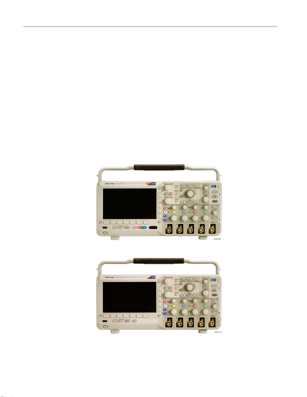
Figure 1: MSO2000B series
Figure 2: DPO2000B series
12 MSO2000B and DPO2000B Installation and Safety Instructions

Operating Requirements
TPP0100 or a TP
P0200
Passive Probe
MSO2000B Series
Oscilloscope with a P6316
Digital Probe
Single-ended
Installation Category II - for measurements performed on circuits directly connected to the
low-voltage installation
Temperature:
Operating: -10 °C to +55 °C (+14 °F to +131 °F)
Nonoperatin
Pollution Degree: 2, Indoor use only
Humidity: 5% to 95% RH
Threshold Accuracy: ±(100 mV + 3% of threshold)
Threshold Range: ±20 V
Maximum nondestructive input signal to probe: ±40 V peak
Minimum s ignal swing: 500 mV
voltage probe (ground referenced): 300 V
g: -51 °C to +71 °C ( -60 °F to +160 °F)
peak-to-peak
CAT II safety requirements
RMS
Input resistance: 101 k
Input capacitance: 8.0 pF
Temperature:
Operating: 0 °C to +50 °C (+32 °F to +122 °F)
Nonoperating: -20 °C to +60 °C (-4 °F to +140 °F)
Altitude:
Operating: 3,000 m (9,843 ft) maximum
Nonoperating: 12,000 m (39,370 ft) maximum
Pollution Degree: 2, Indoor use only
Humidity:
5% to 95% relative humidity
MSO2000B and DPO2000B Installation and Safety Instructions 13
Operating Requirements
Electrical Ratings
Power Requirements
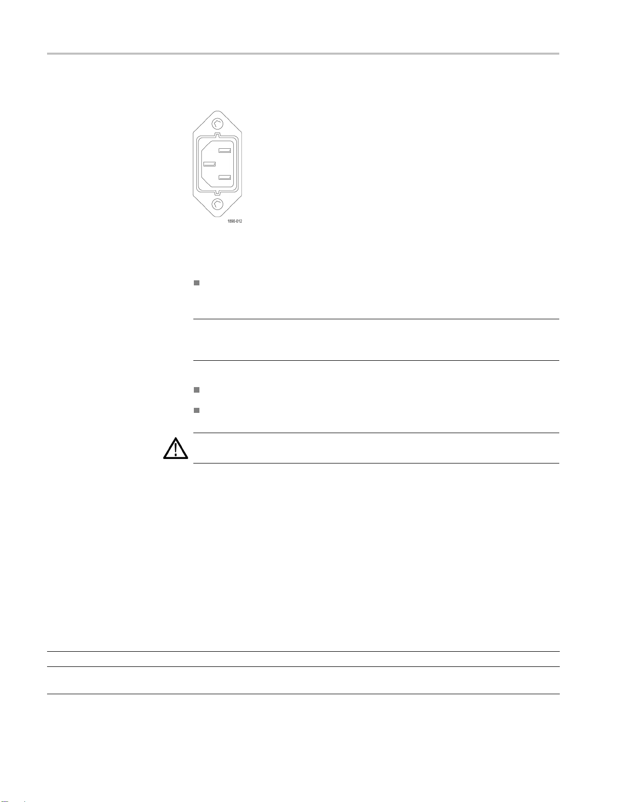
Power connector
The instrument has the following power requirements:
A single-phase power source with one current-carrying conductor at or near
earth-ground (the neutral conductor).
NOTE. Systems with both current-carrying conductors live with respect to ground
(such as
sources.
phase-to-phase in multiphase systems) are not recommended as power
The mains supply frequency must be 50 or 60 Hz.
The mains supply voltage must be in the range from 100 to 240 VAC.
WARNING. To reduce risk of fire and shock, ensure the mains supply voltage
fluctuations do not exceed 10% of the operating voltage range.
Only the line conductor is fused for over-current protection. The fuse is internal
es
Fus
and not user replaceable. Do not attempt to replace the fuse. If you suspect the
fuse has blown, return the instrument to an authorized service center for repair.
Ba
tteries
The instrument does not contain any user-replaceable batteries .
Input Ratings
Table 2: Maximum input voltage
Input Rating
At front-panel BNC connector 300 V RMS, Installation Category II; derate above 4 MHz to 6 V RMS at 200 MHz.
At the P6316 probe input, not at the
instrument input
±40 V peak
14 MSO2000B and DPO2000B Installation and Safety Instructions
Environmental Ratings
Table 3: Environmental specifications
Characteristic Description
Temperature
Humidity
Altitude
Cooling 50 mm (2 inch)
Operating 0 °C to + 50 °C
Nonoperating
Operating High: 40 °C to 50 °C, 10% to 60% RH
Nonoperating
Operating 3,000 m (9,842 ft)
Nonopera
ting
-20°Cto+60°C
Low: 0 °C to
High: 40 °C
Low: 0 °C to 40 °C, 5% to 90% RH
12,000 m (39,370 ft)
CAUTION. To ensure proper cooling, keep the sides and rear of the oscilloscope clear of obstructions.
Operating Requirements
40 °C, 10% to 90% RH
to 60 °C, 5% to 60% RH
Physical Specifications
Table 4: Physical specifications
Characteristic Description
Dimensions
Weight
Height
Width
Depth
Net
Shipping
Cleaning
175 mm (6.885 inches), including the feet but not the handle
377 mm (14.85 inch)
134 mm (5.3 inch), from the feet to the front of the knobs
139 mm (5.47 inch), from the feet to the front of the front cover
3.6 k g (7 lbs 14 oz), stand-alone oscilloscope
Inspect the oscilloscope a nd probes as often as operating conditions require. To
clean the exterior surface, perform the following steps:
1. Remove loose dust on the outside of the oscilloscope and probes with a
lint-free cloth. Use care to avoid scratching the clear glass display filter.
2. Use a soft cloth dampened with water to clean the oscilloscope. Use an
aqueous solution of 75% isopropyl alcohol for more efficient cleaning.
CAUTION. To avoid damage to the surface of the oscilloscope or probes, do not
use any abrasive or chemical cleaning agents.
MSO2000B and DPO2000B Installation and Safety Instructions 15

Installation Procedure
Installation Procedure
Connecting Probes
The oscilloscope supports probes with the following:
1. Tektronix Versatile Probe Interface (TekVPI)
These probes support two-way communication with the oscilloscope through
on-screen menus and remotely through programmable support. The remote
control is useful in applications like an ATE (automated test environment)
where you want the s ystem to preset probe parameters.
NOTE.
MSO2000B and D PO2000B Series oscilloscopes, visit the Oscilloscope Probe
and Accessory Selector tool on the Tektronix website.
2. TPA-BNC Adapter
NOTE. To use a TekVPI probe and a TPA-BNC adapter, connect a TekVPI external
power adapter (Tektronix part number 119
Power connector.
3. Plain BNC Interfaces
For more information on the many probes available for use with
TPA-BNC Adapter allows you to use Tek Probe II probe capabilities,
The
such as providing probe power, and passing scaling and unit information to
the oscilloscope.
‑
7465‑XX) to the side panel Probe
16 MSO2000B and DPO2000B Installation and Safety Instructions

Installation Procedure
Some probes use
scaling to the oscilloscope. Other probes only pass the signal and there is no
communication.
4. Digital Probe Interface (MSO2000B series only)
The P6316 pr
For more information on the many probes available for use with DPO2000B and
MSO2000B se
ries oscilloscopes, refer to www.tektronix.com.
TekProbe capabilities to pass the waveform signal and
obe provides 16 channels of digital (on or off state) information.
MSO2000B and DPO2000B Installation and Safety Instructions 17

Power-On and Power-Off Procedure
Power-On and P
Power-On
ower-Off Procedure
This instrum
conductor at or near earth ground. The line conductor is fused for over-current
protection. A protective ground connection through the grounding conductor in
the power cord is essential for safe operation.
1. Connect the supplied power cord to the rear-panel power connector.
2. Press the p
turn on.
NOTE. The Standby button on the front-panel does not disconnect mains power.
Only the power cord at the rear of the product can disconnect mains power.
ent operates from a single-phase power source with the neutral
ower button on the instrument front-panel and the instrument will
r-Off
Powe
18 MSO2000B and DPO2000B Installation and Safety Instructions
1. Press the power button on the instrument front-panel to turn the instrument off.
2. If you want to remove power completely, disconnect the power cord from the
rear-panel of the instrument.

Power-On and Power-Off Procedure
Functional Ch
eck
Perform this quick functional check to verify that your oscilloscope is operating
correctly.
1. Connect the oscilloscope power cable as described in Powering On the
Oscilloscope. (See page 18, Power-On and Power-Off Procedure.)
2. Power on the oscilloscope.
3. Connect the proper TPP0100 or TPP0200 probe tip and reference lead to the
PROBE COMP connectors on the oscilloscope.
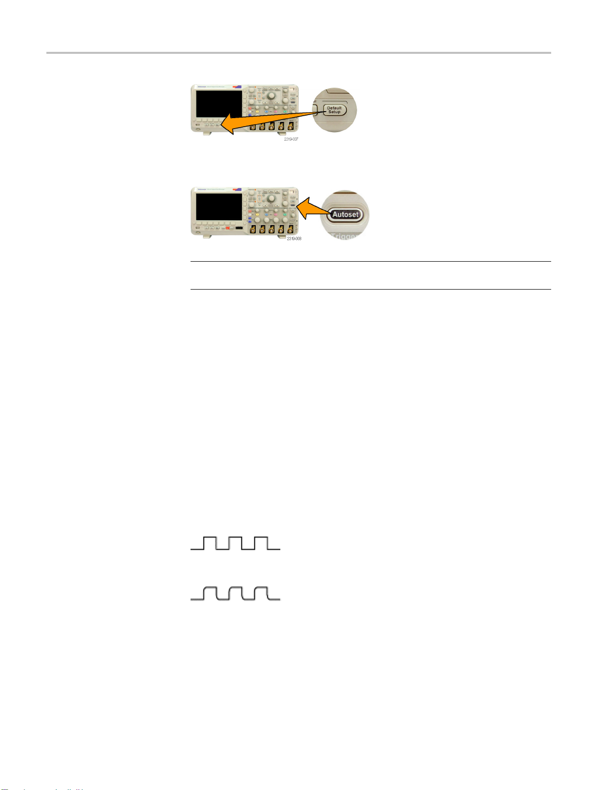
sh Default Setup.
4. Pu
MSO2000B and DPO2000B Installation and Safety Instructions 19
Power-On and Power-Off Procedure
5. Push Autoset
5Vat1kHz.
NOTE. For best perform ance, it is recommended that you set the Vertical scale to
1V.
If the signal appears but is misshapen, perform the procedures for
compens
If no signal appears, rerun the procedure. If this does not remedy the situation,
have th
. The screen should now display a square wave, approximately
ating the probe. (See page 20.)
e oscilloscope serviced by qualified service personnel.
Compensating a P assive Voltage Probe
Whene
compensate the probe to match it to the corresponding oscilloscope input channel.
ver you attach a passive voltage probe for the first time to any input channel,
operly compensate your passive p robe:
To pr
1. Follow the steps for the functional check. (See page 19.)
2. Check the shape of the displayed waveform to determine if your probe is
properly compensated.
Figure 3: Properly compensated
Figure 4: Under compensated
20 MSO2000B and DPO2000B Installation and Safety Instructions
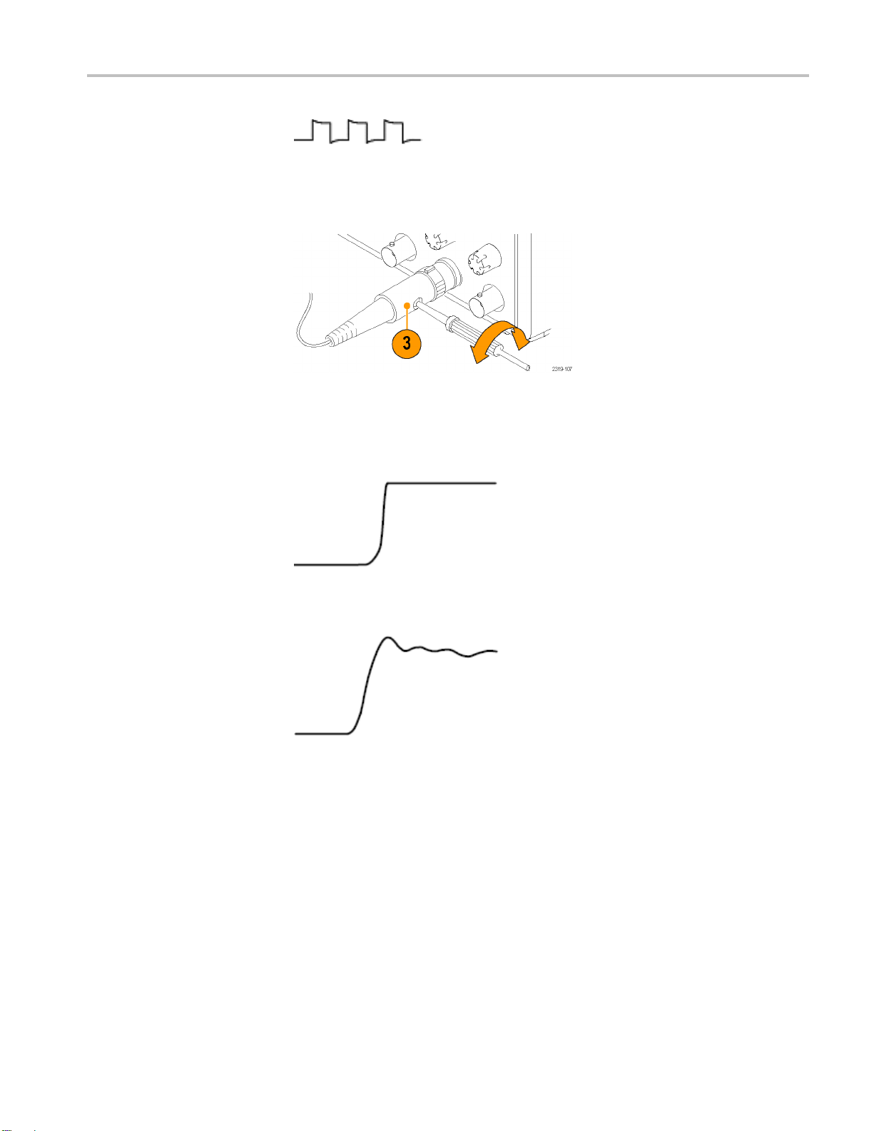
Power-On and Power-Off Procedure
Quick Tips
Figure 5: Over
3. If necessary
Use the shortest possible ground lead and signal path to minimize probe-induced
ringing and distortion on the measured signal.
compensated
, adjust your probe. Repeat as needed.
Figure 6: Signal with a short ground lead
Figure 7: Signal with a long ground lead
Application Module Free Trial
A 30-day free trial is available f or all application modules not installed in your
oscilloscope. The trial period begins when you power on the oscilloscope for
the first time.
After 30 days, you must purchase the module if you want to continue using the
application. To see the date when your free trial period expires, push the front
panel Utility button, push the lower-bezel Utility Page button, use multipurpose
knob a to select Config, and push the lower-bezel About button.
MSO2000B and DPO2000B Installation and Safety Instructions 21
Power-On and Power-Off Procedure
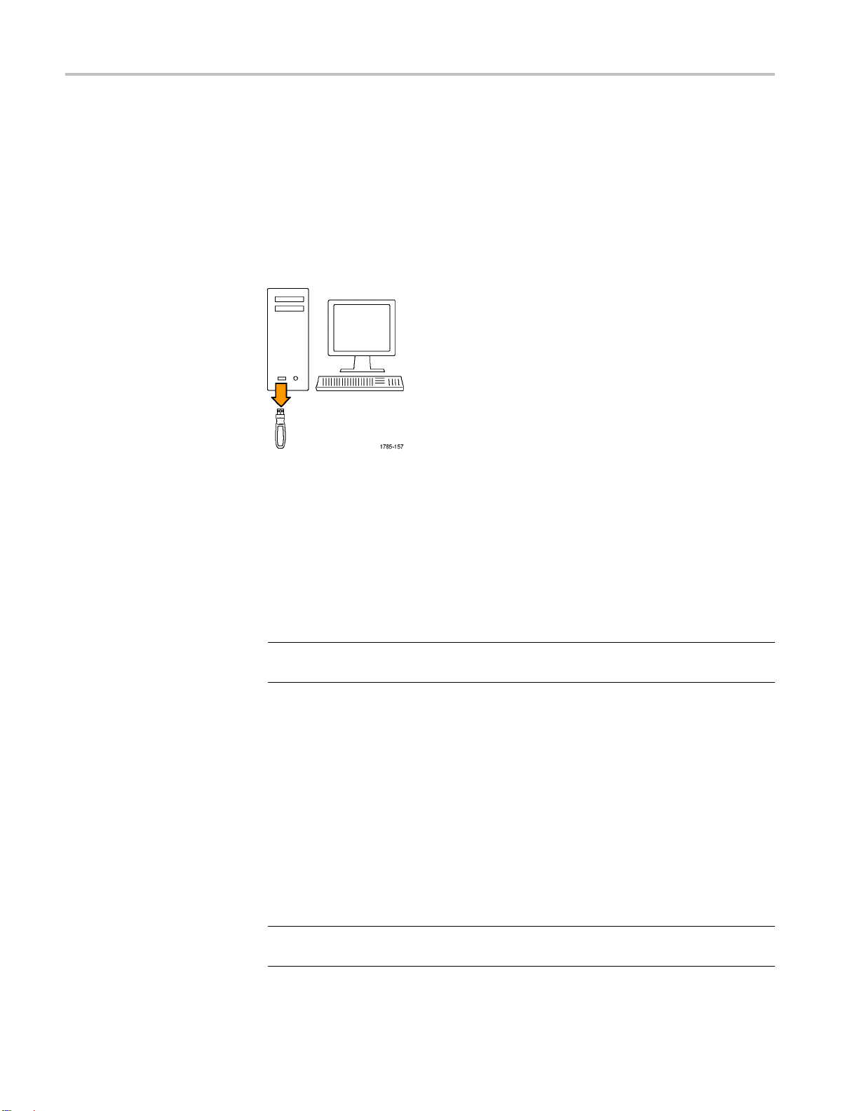
Upgrading Firmware
To upgrade the firmware of the oscilloscope:
1. Open up a Web browser and go to www.tektronix.com/software. Proceed to
the software finder. Download the latest firmware for your oscilloscope on
your PC.
Unzip the files and copy the firmware.img file into the root folder of a USB
flash drive.
2. Power off your oscilloscope.
3. Insert the USB flash drive into the front-panel USB port on your oscilloscope.
4. Power on the oscilloscope. The oscilloscop
installs the replacement firmware.
If the oscilloscope does not install the firmware, rerun the procedure. If
the problem continues, try a different model of USB flash drive. Finally, if
needed, contact qualified service personnel.
NOTE. Do not power off the oscilloscope or remove the USB flash drive until the
scope finishes installing the firmware.
oscillo
5. Power off the oscilloscope and remove the USB flash drive.
6. Power on the oscilloscope.
7. Push Utility.
8. Push Utility Page.
9. Turn multipurpose knob a and select Config.
10. Push About. The oscilloscope displays the firmware version number.
e automatically recognizes and
11. Confirm that the version number matches that of the new firmware.
NOTE. For more information on updating the firmware, refer to the electronic
(PDF) MSO/DPO2000B User Manual.
22 MSO2000B and DPO2000B Installation and Safety Instructions

Power-On and Power-Off Procedure
Connecting Yo
ur Oscilloscope to a Computer
You m ay want to document your work for future reference. Instead of saving
screen images and waveform data to a USB flash drive and generating a report
later, you ma
remote PC for analysis. You may also want to control an oscilloscope at a remote
location from your computer.
Two ways to connect your oscilloscope to a computer are through the VISA
(Virtual Instrument Software Architecture) drivers and the e*Scope Web-enabled
tools. Use VISA to communicate with your oscilloscope from y our computer
through a software application. Use e*Scope to communicate with your
oscilloscope through a Web browser.
NOTE. Fo
including instructions on how to save screen images and waveform data, refer to
the electronic (PDF) MSO/DPO2000B User Manual.
y want to get a copy of the image or waveform data directly from a
r more information on connecting your oscilloscope to a computer,
MSO2000B and DPO2000B Installation and Safety Instructions 23
Getting Acquainted with the Oscilloscope
Getting Acqua
inted with the Oscilloscope
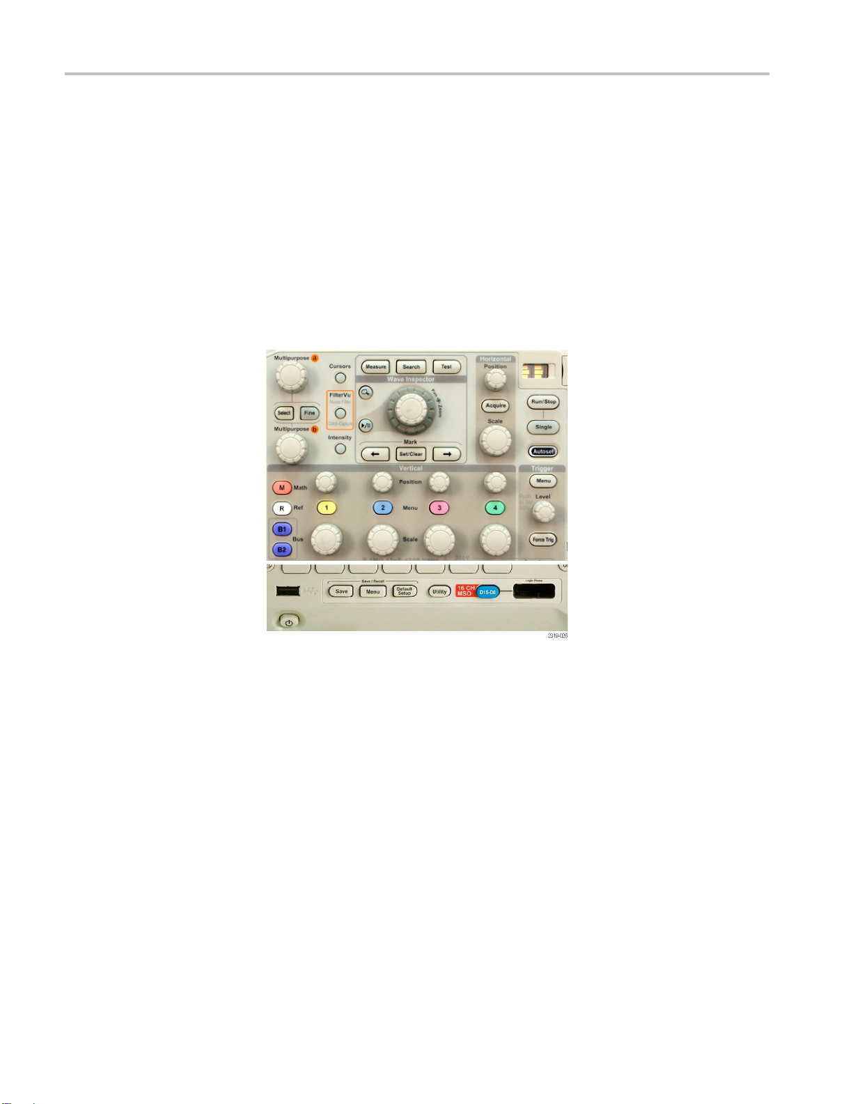
Front-Panel Menus and Controls
The front pa
Use the menu buttons to access more specialized functions.
Using the Menu System
To use the menu system:
1. Push a front-panel menu button to display the m enu that you want to use.
nel has buttons and controls for the functions that you use most often.
24 MSO2000B and DPO2000B Installation and Safety Instructions
 Loading...