


xx
MSO2000B and DPO2000B Series
Oscilloscopes
ZZZ
Installation and Safety
Instructions
*P071307801*
071-3078-01


xx
MSO2000B and DPO2000B Series
Oscilloscopes
ZZZ
Installation and Safety
Instructions
www.tektronix.com
071-3078-01

Copyright © Tektronix. All rights reserved. Licensed software products are owned by Tektronix or its subsidiaries
or suppliers, and are protected by national copyright laws and international treaty provisions.
Tektronix products are covered by U.S. and foreign patents, issued and pending. Information in this publication
supersedes that in all previously published material. Specifications and price change privileges reserved.
TEKTRONIX and TEK are registered trademarks of Tektronix, Inc.
Contacting Tektronix
Tektronix, Inc.
14150 SW Karl Braun Drive
P.O. Box 500
Beaverto
USA
For product information, sales, service, and technical support:
n, OR 97077
In North America, call 1-800-833-9200.
Worl dwid e, visi t www.tektronix.com to find contacts in your area.

Table of Contents
Preface ............................................................................................................... 1
Accessories and Replaceable Parts .......................................................................... 1
Documentation ................................................................................................. 4
General Safety Summary .......................................................................................... 5
Compliance Information........................................................................................... 7
EMC Compliance............................. ................................ ................................ . 7
Safety Compliance............................................................................................. 9
Environmental Considerations ........................................ ................................ ...... 11
Operating Requirements .......................................................................................... 12
Electrical Ratings ............................................................................................. 14
Input Ratings .. ................................ ................................ ................................ 14
Environmental Ratings ....................................................................................... 15
Physical Specifications....................................................................................... 15
Installation Procedure............................................................................................. 16
Power-On and Power-Off Procedure ............................................................................ 18
Functional Check ............................................................................................. 19
Compensating a Passive Voltage Probe .................................................................... 20
plication Module Free Trial .............................................................................. 21
Ap
Upgrading Firmware ....................... ................................ ................................ .. 22
Connecting Your Oscilloscope to a Computer... . . .... . . .... . . .... . ..... . ..... . ..... . ..... . ..... . ..... . ... 23
Getting Acquainted with the Oscilloscope.. . ..... . ..... ..... . ..... . ..... . .... . ..... . ..... . ... . . ..... . ..... . .... 24
Front-Panel Menus and Controls............................................................................ 24
Front-Panel Connectors ........ ................................ ................................ .............. 31
Side-Panel Connector ........................................................................................ 31
Rear-Panel Connectors....................................................................................... 32
まえがき .................................................................................................. 33
アクセサリと交換部品 ............................................................................... 33
マニュアル ........................................................................................... 37
安全にご使用いただくために .......................................................................... 38
適合性に関する情報.................................................................................... 40
EMC 適合性 ......................................................................................... 40
安全性 ............................................................................................... 42
環境への配慮 ....................................................................................... 44
動作の要件 .............................................................................................. 45
電気定格 ............................................................................................ 47
入力定格 ............................................................................................ 47
環境要件 ............................................................................................ 48
物理仕様 ............................................................................................ 48
MSO2000B and DPO2000B Installation and Safety Instructions i

Table of Contents
インストール手順 ........................................................................................ 49
電源投入、電源切断の手順............................................................................ 51
機能チェック......................................................................................... 52
受動電圧プローブの補正 .......................................................................... 53
アプリケーション・モジュールの無料トライアル ................................................... 54
ファームウェアのアップグレード.................................................................... 55
オシロスコープとコンピュータの接続 .............................................................. 56
オシロスコープの概要 .................................................................................. 57
フロント・パネル・メニューとコントロール........................................................... 57
フロント・パネル・コネクタ ........................................................................... 64
サイド・パネル・コネクタ............................................................................. 65
リア・パネル・コネクタ ............................................................................... 65
前言 ...................................................................................................... 68
附件和可更换部件 ................................................................................. 68
文档 .................................................................................................. 72
常规安全概要 ........................................................................................... 73
符合性信息 .............................................................................................. 76
EMC 符合性 .......................................................................................... 76
安全符合性.......................................................................................... 78
环境注意事项....................................................................................... 80
操作要求................................................................................................. 81
电气额定值.......................................................................................... 83
输入额定值.......................................................................................... 83
环境额定值.......................................................................................... 84
物理技术规格....................................................................................... 84
安装步骤................................................................................................. 85
开机和关机步骤 ........................................................................................ 87
功能检查 ............................................................................................ 88
补偿无源电压探头 ................................................................................. 89
应用模块免费试用 ................................................................................. 90
升级固件 ............................................................................................ 91
将示波器连接到计算机............................................................................ 92
熟悉示波器 .............................................................................................. 92
前面板菜单和控制 ................................................................................. 92
前面板连接器....................................................................................... 99
侧面板连接器....................................................................................... 99
后面板连接器...................................................................................... 100
ii MSO2000B and DPO2000B Installation and Safety Instructions

Preface
This manual describes the installation and operation of the following
oscilloscopes:
DPO2002B DPO2004B DPO2012B
DPO2014B DPO2022B DPO2024B
MSO2002B MSO2004B MSO2012B
MSO2014B MSO2022B MSO2024B
Important safety precautions to avoid injury and prevent damage to this
product or any products connected to it
EMC (electromagnetic compliance), safety, and environmental standards with
which the product complies
Voltage, power, and environmental requirements to use the product
Installation procedure
Power-on and power-off procedure
Front- and rear-panel controls and connectors
Accessories and Replaceable Parts
Standard Accessories
Accessory Description
DPO2000B and MSO2000B
Series Oscilloscopes Installation
and Safety Instructions
DPO2000B and MSO2000B
Series Oscilloscopes
Documentation C D
Tektronix OpenChoice Desktop
PC Communications CD
Calibration certificate
documenting traceability to
national metrology institute(s),
and ISO9001 quality system
registration
Provides safety and compliance
information along with hardware
installation instructions to present
the associated safety warnings.
This manual is available in English,
Simplified Chinese, and Japanese
Electronic versions of documents,
including the Programmer Manual
and the Technical Reference.
Productivity, analysis, and
documentation software.
Tektronix part
number
071-3078‑XX
063-4472‑XX
063-4402‑XX
——
MSO2000B and DPO2000B Installation and Safety Instructions 1

Preface
Standard Accessories, (cont.)
Accessory Description
Front panel overlay
For DPO2000B and
MSO2000B series: Probes
For MSO2000B series: Digital
probe
For MSO2000B series:
Accessories pouch
Five year warranty
Power cord
French (Option L1)
Italian (Option L2)
German (Option L3)
Spanish (Option L4)
Japanese (Option L5)
Portuguese (Option L6)
Simple Chinese (Option L7)
Traditional Chinese (Option L8)
Korean (Option L9)
Russian (Option L10)
For models 100 MHz bandwidth:
One 200 MHz, 10X passive voltage
probe with 10 M input resistance
per channel
For models < 100 MHz bandwidth:
One 100 MHz, 10X passive voltage
probe with 10 M input resistance
per channel
One, 16-channel digital probe
Pouch that attaches to the handle
for carrying probes and other
accessories.
For details, refer to the warranty
in the front of the electronic (PDF)
user manual
North America (Option A0)
Universal Euro (Option A1)
United Kingdom (Option A2)
Australia (Option A3)
Switzerland (Option A5)
Japan (Option A6)
China (Op tion A10)
India (Option A11)
Brazil (Option A12)
No power cord or AC adapter
(Option A99)
Tektronix part
number
335-2020-00
335-2021-00
335-2022-00
335-2023-00
335-2024-00
335-2025-00
335-2026-00
335-2027-00
335-2028-00
335-2029-00
TPP0200
TPP0100
P6316
016-2008-00
——
161-0348-00
161-0343-00
161-0344-00
161-0346-00
161-0347-00
161-0342-00
161-0341-00
161-0349-00
161-0356-00
——
2 MSO2000B and DPO2000B Installation and Safety Instructions

Preface
Optional Acces
Accessory Description Tektronix par
DPO2EMBD
DPO2AUTO
DPO2COMP
DPO2CONN The conne
NEX-HD2HEADER
TekVPI probes that work with
MSO/DP
Note: These probes require the use
of the TekVPI external power adapter
listed
TekVPI external power adapter
TPA-B
Note: This adapter requires the use
of the TekVPI external power adapter
list
Deskew pulse generator Deskew pulse generator and signal source with TekVPI
Power measurement deskew and
cal
TEK-USB-488 Adapter GPIB to USB Adapter TEK-USB-488
Ra
S
Hard transit case
DPO2000B and MSO2000B Series
Oscilloscopes Service manual
DPO2000B and MSO2000B Series
Oscilloscopes Application Module
Installation
O2000B Series oscilloscopes
below.
NC
ed above.
ibration fixture
ckmount kit
oft transit case
sories
The embedded serial triggering and analysis module
enables trigg
SPI serial buses, as well as bus views, bus decoding,
search tools, and packet decode tables with timestamp
information
The automotive serial triggering and analysis module
enables trig
and LIN serial buses, as well as bus views, bus decoding,
search tools, and packet decode tables with timestamp
informatio
The computer triggering and analysis module enables
triggerin
buses, search tools, bus views, bus decoding in hex,
binary, and ASCII, and decode tables with timestamp
informati
remote programmability and a Video Out port to display
the oscilloscope screen on an external monitor
Adapter that routes the channels from a Mictor connector
to 0.1 i n
Visit t
Tool on the Tektronix website at www.tektronix.com
Suppl
TekV P
illoscope interface
osc
verts TEK-DPG pulse generator output into a series
Con
of test point connections
ds rackmount brackets
Ad
ase for carrying an oscilloscope
C
raveling hard case, which requires use of the soft transit
T
case (ACD2000)
Service information on DPO2000B and MSO2000B series
oscilloscopes
Describes how to install application modules in
DPO2000B and MSO2000B series oscilloscopes
ering on packet level information on I
gering on packet level information on CAN
n
g on RS-232, RS -422, RS-485 and UART serial
on
ctivity module adds an Ethernet port for
ch header pins
he Oscilloscope Probe and Accessory Selector
ies external power to a TekVPI probe
I to TekProbe II BNC Adapter
2
C and
DPO2EMBD
DPO2AUTO
DPO2COMP
DPO2CONN
NEX-HD2HEADER
119 ‑7465‑XX
NC
TPA-B
-DPG
TEK
067-1686-00
D2000
RM
CD2000
A
CTEK4321
H
077-0737‑XX
071-2330‑XX
tnumber
MSO2000B and DPO2000B Installation and Safety Instructions 3

Preface
Documentation
The following table lists the documentation that is a vailable for the product and
shows where you can find it: in a printed manual, on the product documentation
CD-ROM, or on the Tektronix Web site at www.tektronix.com.
Table 1: Product documentation
Item Purpose Location
Installation and Safety Instructions (this
manual)
User Manual Provides operation and application
Specifications and Performance
Verification Technical Reference
Programmer M anual
Service Manual Provides information about adjustments,
Provides safety and compliance
information along with hardware
installation instructions to present the
associated safety warnings. This manual
is available in English, Japanese, and
Simplified Chinese
information. This manual is available
in English, French, Italian, German,
Spanish, Japanese, Portuguese,
Simplified Chinese, Traditional Chinese,
Korean, and Russian
Specifications and procedures for
checking instrument performance.
Command reference for remotely
controlling the instrument.
repair, and replaceable parts.
Printed manual and also
available in electronic format at
www.tektronix.com/manuals
Product Documentation CD and available
at www.tektronix.com/manuals
Product Documentation CD and available
at www.tektronix.com/manuals
Product Documentation CD and available
at www.tektronix.com/manuals
Available at www.tektronix.com/manuals
4 MSO2000B and DPO2000B Installation and Safety Instructions

General Safety Summary
General Safet
To Avoid Fire or Personal
Injury
ySummary
Review the fo
this product or any products connected to it.
To avoid potential hazards, use this product only as specified.
Only qualified personnel should perform service procedures.
While using this product, you may need to access other parts of a larger system.
Read the safety sections of the other component manuals for warnings and
cautions related to operating the system.
Use Proper Power Cord. Use only the power cord specified for this product and
certified for the country of use.
Connect and Disconnect Properly. Do not connect or disconnect probes or test
leads while they are connected to a voltage source.
Connect and Disconnect Properly. De-energize the circuit under test before
connecting or disconnecting the current probe.
Ground the Product. This product is grounded through the grounding conductor
of the power cord. To
connected to earth ground. Before making connections to the input or output
terminals of the product, ensure that the product is properly grounded.
llowing safety precautions to avoid injury and prevent damage to
avoid electric shock, the grounding conductor must be
Observe A ll Terminal Ratings. To avoid fire or shock hazard, observe all ratings
and markings on the product. Consult the product manual for further ratings
information before making connections to the product.
Connect the probe reference lead to earth ground only.
Do not apply a potential to any terminal, including the common terminal, that
exceeds the maximum rating of that terminal.
Power Disconnect. The power cord d
source. Do not block the power cord; it must remain accessible to the user at
all times.
Do Not Operate Without Covers. Do not operate this product with covers or
panels removed.
Do Not Operate With Suspected Failures. If you suspect that there is damage to
this product, have it inspected by qualified service personnel.
Avoid Exposed Circuitry. Do not touch exposed connections and components
when power is present.
isconnects the product from the power
MSO2000B and DPO2000B Installation and Safety Instructions 5
General Safety Summary
TermsinthisManual
Symbols and Terms on the
Product
Do Not Operate i
Do Not Operate in an Explosive Atmosphere.
Keep Product Surfaces Clean and Dry.
Provide Prop
details on installing the product so it has proper ventilation.
These terms may appear in this manual:
WARNING.
in injury or loss of life.
CAUTION
damage to this product or other property.
These t
. Caution statements identify conditions or practices that could result in
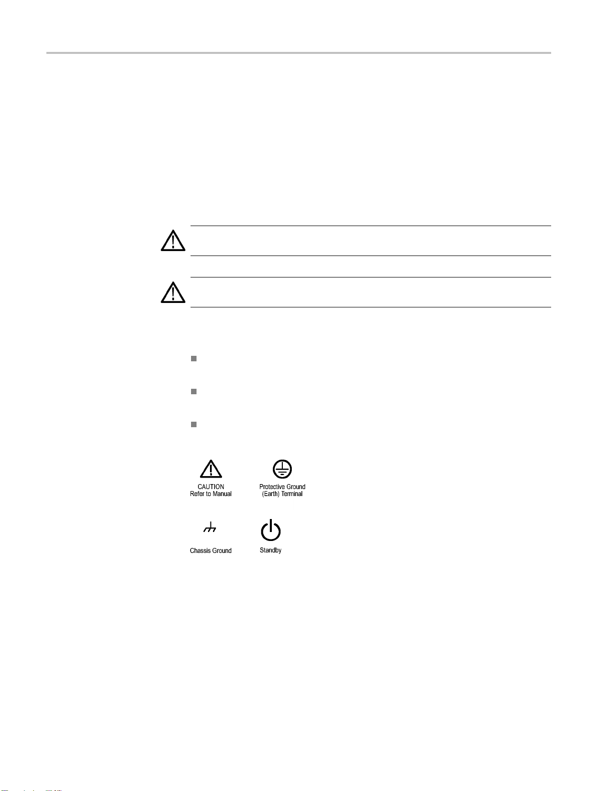
erms may appear on the product:
DANGER indicates an injury hazard immediately accessible as you read
the ma
n Wet/Damp Conditions.
er Ventilation. Refer to the manual’s installation instructions for
Warning statements identify conditions or practices that could result
rking.
WARNING indicates an injury hazard not immediately accessible as you
the marking.
read
CAUTION indicates a hazard to property including the product.
The following symbol(s) may appear on the product:
6 MSO2000B and DPO2000B Installation and Safety Instructions

Compliance Information
Compliance In
EMC Compliance
EC Declaration of
Conformity – EMC
formation
This section
environmental standards with which the instrument complies.
Meets intent of Directive 2004/108/EC for Electromagnetic Compatibility.
Compliance was demonstrated to the following specifications as listed in the
Official Journal of the European Communities:
EN 61326-1:2006, EN 61326-2-1:2006. EMC requirements for electrical equipment
for measurement, control, and laboratory use.
CISPR 11:2003. Radiated and conducted emissions, Group 1, Class A
IEC 61000-4-2:2001. Electrostatic discharge immunity
IEC 61000-4-3:2002. RF electromagnetic field immunity
IEC 61000-4-4:2004. Electrical fast transient/burst immunity
IEC 61000-4-5:2001. Power line surge immunity
IEC 61000-4-6:2003. Conducted RF immunity
IEC 61000-4-11:2004. Voltage dips and interruptions immunity
lists the EMC (electromagnetic compliance), safety, and
123
4
5
6
EN 61000-3-2:2006. AC power line harmonic emissions
EN 61000-3-3:1995. Vo ltage changes, fluctuations, and flicker
European Contact.
Tektronix UK, Ltd.
Western Peninsula
West ern Roa d
Bracknell, RG12 1RF
United Kingdom
United Kingdom
1
This product is intended for use in nonresidential areas only. Use in residential areas may cause electromagnetic
interference.
2
Emissions which exceed the levels required by this standard may occur when this equipment is connected to a
test object.
3
To ensure compliance with the EMC standards listed here, high quality shielded interface cables should be used.
4
Trace bloom not exceeding 4 divisions pk-to-pk may be induced under the conditions of the IEC 61000-4-3 test.
5
Trace bloom not exceeding 1 division pk-to-pk may be induced under the conditions of the IEC 61000-4-6 test.
6
Performance Criterion C applied at the 70%/25 cycle Voltage-Dip and the 0%/250 cycle Voltage-Interruption test
levels (IEC 61000-4-11).
MSO2000B and DPO2000B Installation and Safety Instructions 7

Compliance Information
Australia / New Zealand
Declaration of
Conformity – EMC
7
Add text here to
list inrush current information.
Complies with the EMC provision of the Radiocommunications Act per the
following standard, in accordance with ACMA:
CISPR 11:2003. Radiated and Conducted Emissions, Group 1, Class A, in
accordance with EN 61326-1:2006 and EN 61326-2-1:2006.
Australia / New Zealand contact.
Baker & McK
enzie
Level 27, AMP Centre
50 Bridge Street
Sydney NSW 2000, Australia
8 MSO2000B and DPO2000B Installation and Safety Instructions

Compliance Information
Safety Compli
ance
EC Declaration of
Conformity – Low Voltage
U.S. Natio
nally Recognized
Testing Laboratory Listing
Canadian Certification
Additional Compliances
Equipment Type
Compliance was demonstrated to the following specification as listed in the
Official Journal of the European Communities:
Low Voltage Directive 2006/95/EC.
EN 61010-1: 2001. Safety requirements for electrical equipment for
measurement control and laboratory use.
UL 61010-1:2004, 2ndEdition. Standard for electrical measuring and test
equipment.
CAN/CSA-C22.2 No. 61010-1:2004. Safety requirements for electrical
equipment for measurement, control, and laboratory use. Part 1.
IEC 61010-1: 2001. Safety requirements for electrical equipment for
measurement, control, and laboratory use.
nd measuring equipment.
Test a
Safety Class
Pollution Degree
Description
Class1–groundedproduct.
A measure of the contaminants that could occur in the environment around
and within a product. Typically the internal environment inside a product is
considered to be the same as the external. Products should be used only in the
environment for which they are rated.
Pollution Degree 1. No pollution or only dry, nonconductive pollution occurs.
Products in this category are generally encapsulated, hermetically sealed, or
cated in clean rooms.
lo
Pollution Degree 2. Normally only dry, nonconductive pollution occurs.
ccasionally a temporary conductivity that is caused by condensation must
O
be expected. This location is a typical office/home environment. Temporary
condensation occurs only when the product is out of service.
Pollution Degree 3 . Conductive pollution, or dry, nonconductive pollution
that becomes conductive due to condensation. These are sheltered locations
where neither temperature nor humidity is controlled. The area is protected
from direct sunshine, rain, or direct wind.
Pollution Degree 4. Pollution that generates persistent conductivity through
conductive dust, rain, or snow. Typical outdoor locations.
MSO2000B and DPO2000B Installation and Safety Instructions 9

Compliance Information
Pollution Degree
Installation (Overvoltage)
Category Descriptions
Overvoltage Category
Pollution Degr
Terminals on this product may have different installation (overvoltage) category
designations. The installation categories are:
Measurement Category IV. For measurements performed at the source o f
low-voltage installation.
Measurement Category III. For measurements performed in the building
installation.
Measurement Category II. For measurements performed on circuits directly
connected to the low-voltage installation.
Measurement Category I. For measurements performed on circuits not
directly connected to MAINS.
Overvol
ee 2 (as defined in IEC 61010-1). Note: Rated for indoor use only.
tage Category II (as defined in IEC 61010-1)
10 MSO2000B and DPO2000B Installation and Safety Instructions
Compliance Information
Environmenta
Product End-of-Life
l Considerations
This section provides information about the environmental impact of the product.
Observe the following guidelines when recycling an instrument or component:
Handling
Equipment Recycling. Production of this equipment required the extraction and
use of natural resources. The equipment may contain substances that could be
harmful to
end of life. In order to avoid release of such substances into the environment and
to reduce the use of natural resources, we encourage you to recycle this product
in an appropriate system that will ensure that most of the materials are reused or
recycled appropriately.
Mercur
mercury. Disposal may be regulated due to environmental considerations. Please
contact your local authorities or, within the United States, refer to the E-cycling
Central Web page (www.eiae.org) for disposal or recycling information.
yNotification. This product uses an LCD backlight lamp that contains
the environment or human health if improperly handled at the product’s
This sym
Union requirements according to Directives 2002/96/EC and 2006/66/EC
on waste electrical and electronic equipment (WEEE) and batteries. For
informa
Tektronix Web site (www.tektronix.com).
bol indicates that this product complies with the applicable European
tion about recycling options, check the Support/Service section of the
Restriction of Hazardous
Substances
This product has been classified as Monitoring and Control equipment, and is
outside the scope of the 2002/95/EC RoHS Directive.
MSO2000B and DPO2000B Installation and Safety Instructions 11
Operating Requirements
Operating Req
DPO2000B and MSO2000B
Series Oscilloscopes
uirements
This section
product safely and correctly. Refer to the complete product specifications in the
MSO/DPO2000B Technical Reference for additional information.
Power Supply Input Voltage: 100 V to 240 V ± 10%
Power Supply Input Power Frequency:
50/60 Hz at 100 V to 240 V
400 Hz at 115 V
Power Consumption: 80 W maximum
Input Voltage (between the signal and reference): 300 V
Installation Category II - for measurements performed on circuits directly
connected to the low-voltage installation
provides the specifications that you need to know to operate your
CAT II
RMS
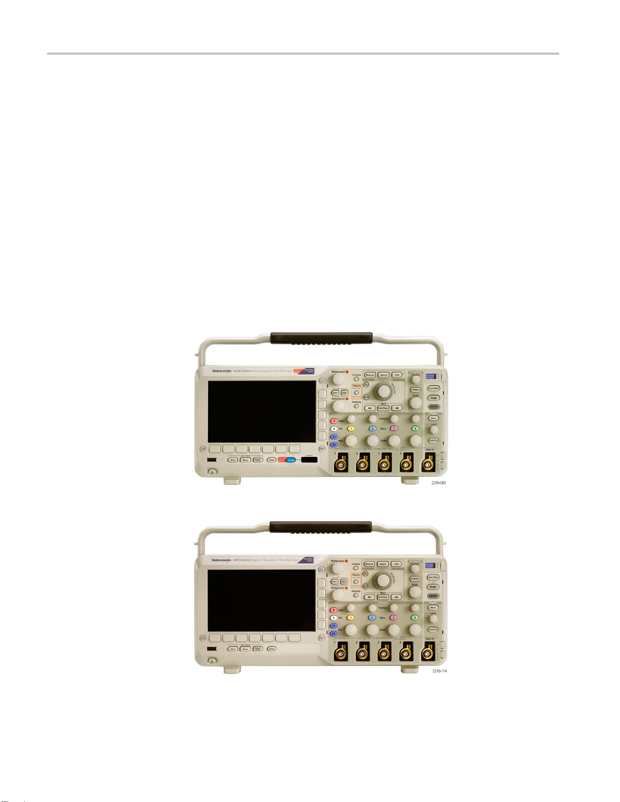
Figure 1: MSO2000B series
Figure 2: DPO2000B series
12 MSO2000B and DPO2000B Installation and Safety Instructions

Operating Requirements
TPP0100 or a TP
P0200
Passive Probe
MSO2000B Series
Oscilloscope with a P6316
Digital Probe
Single-ended
Installation Category II - for measurements performed on circuits directly connected to the
low-voltage installation
Temperature:
Operating: -10 °C to +55 °C (+14 °F to +131 °F)
Nonoperatin
Pollution Degree: 2, Indoor use only
Humidity: 5% to 95% RH
Threshold Accuracy: ±(100 mV + 3% of threshold)
Threshold Range: ±20 V
Maximum nondestructive input signal to probe: ±40 V peak
Minimum s ignal swing: 500 mV
voltage probe (ground referenced): 300 V
g: -51 °C to +71 °C ( -60 °F to +160 °F)
peak-to-peak
CAT II safety requirements
RMS
Input resistance: 101 k
Input capacitance: 8.0 pF
Temperature:
Operating: 0 °C to +50 °C (+32 °F to +122 °F)
Nonoperating: -20 °C to +60 °C (-4 °F to +140 °F)
Altitude:
Operating: 3,000 m (9,843 ft) maximum
Nonoperating: 12,000 m (39,370 ft) maximum
Pollution Degree: 2, Indoor use only
Humidity:
5% to 95% relative humidity
MSO2000B and DPO2000B Installation and Safety Instructions 13
Operating Requirements
Electrical Ratings
Power Requirements
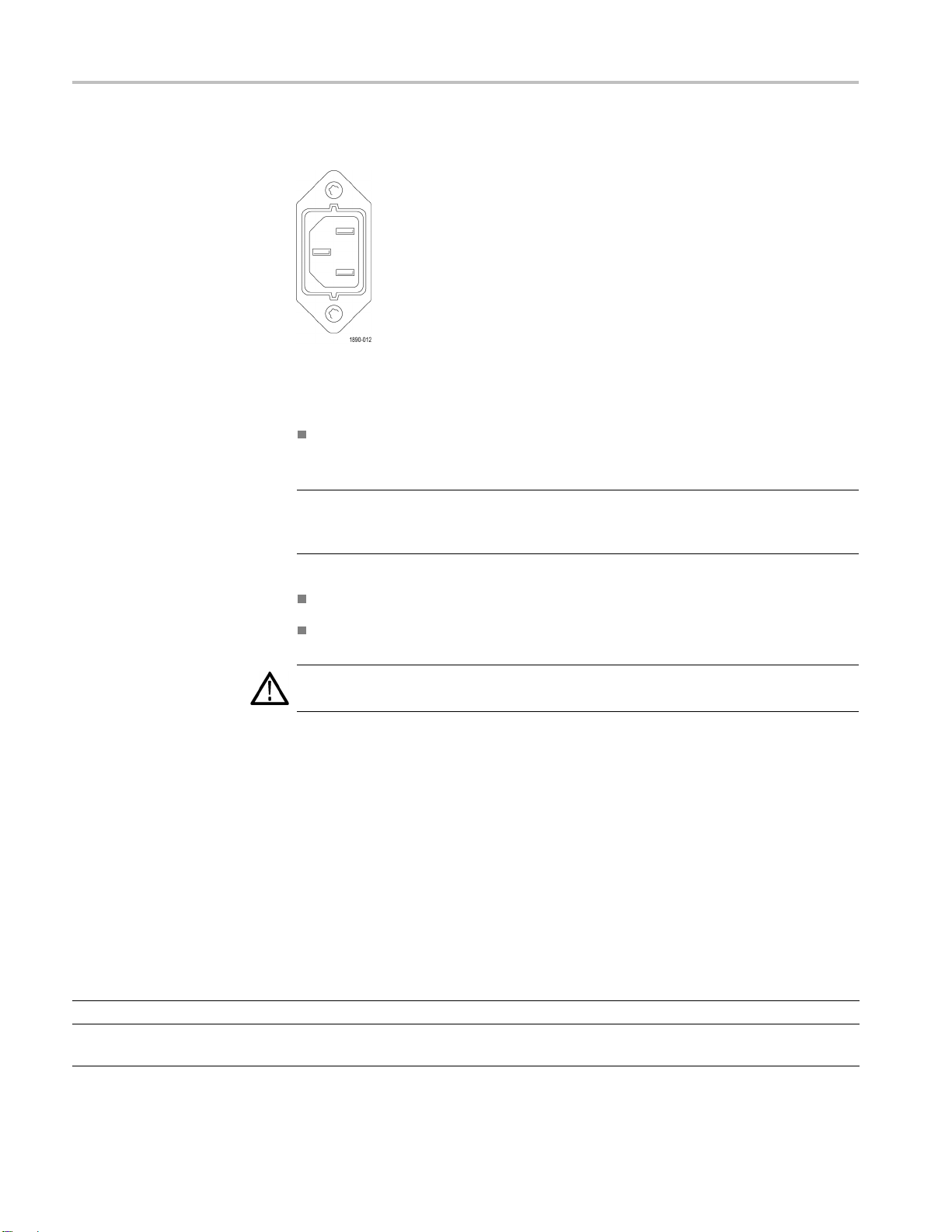
Power connector
The instrument has the following power requirements:
A single-phase power source with one current-carrying conductor at or near
earth-ground (the neutral conductor).
NOTE. Systems with both current-carrying conductors live with respect to ground
(such as
sources.
phase-to-phase in multiphase systems) are not recommended as power
The mains supply frequency must be 50 or 60 Hz.
The mains supply voltage must be in the range from 100 to 240 VAC.
WARNING. To reduce risk of fire and shock, ensure the mains supply voltage
fluctuations do not exceed 10% of the operating voltage range.
Only the line conductor is fused for over-current protection. The fuse is internal
es
Fus
and not user replaceable. Do not attempt to replace the fuse. If you suspect the
fuse has blown, return the instrument to an authorized service center for repair.
Ba
tteries
The instrument does not contain any user-replaceable batteries .
Input Ratings
Table 2: Maximum input voltage
Input Rating
At front-panel BNC connector 300 V RMS, Installation Category II; derate above 4 MHz to 6 V RMS at 200 MHz.
At the P6316 probe input, not at the
instrument input
±40 V peak
14 MSO2000B and DPO2000B Installation and Safety Instructions
Environmental Ratings
Table 3: Environmental specifications
Characteristic Description
Temperature
Humidity
Altitude
Cooling 50 mm (2 inch)
Operating 0 °C to + 50 °C
Nonoperating
Operating High: 40 °C to 50 °C, 10% to 60% RH
Nonoperating
Operating 3,000 m (9,842 ft)
Nonopera
ting
-20°Cto+60°C
Low: 0 °C to
High: 40 °C
Low: 0 °C to 40 °C, 5% to 90% RH
12,000 m (39,370 ft)
CAUTION. To ensure proper cooling, keep the sides and rear of the oscilloscope clear of obstructions.
Operating Requirements
40 °C, 10% to 90% RH
to 60 °C, 5% to 60% RH
Physical Specifications
Table 4: Physical specifications
Characteristic Description
Dimensions
Weight
Height
Width
Depth
Net
Shipping
Cleaning
175 mm (6.885 inches), including the feet but not the handle
377 mm (14.85 inch)
134 mm (5.3 inch), from the feet to the front of the knobs
139 mm (5.47 inch), from the feet to the front of the front cover
3.6 k g (7 lbs 14 oz), stand-alone oscilloscope
Inspect the oscilloscope a nd probes as often as operating conditions require. To
clean the exterior surface, perform the following steps:
1. Remove loose dust on the outside of the oscilloscope and probes with a
lint-free cloth. Use care to avoid scratching the clear glass display filter.
2. Use a soft cloth dampened with water to clean the oscilloscope. Use an
aqueous solution of 75% isopropyl alcohol for more efficient cleaning.
CAUTION. To avoid damage to the surface of the oscilloscope or probes, do not
use any abrasive or chemical cleaning agents.
MSO2000B and DPO2000B Installation and Safety Instructions 15

Installation Procedure
Installation Procedure
Connecting Probes
The oscilloscope supports probes with the following:
1. Tektronix Versatile Probe Interface (TekVPI)
These probes support two-way communication with the oscilloscope through
on-screen menus and remotely through programmable support. The remote
control is useful in applications like an ATE (automated test environment)
where you want the s ystem to preset probe parameters.
NOTE.
MSO2000B and D PO2000B Series oscilloscopes, visit the Oscilloscope Probe
and Accessory Selector tool on the Tektronix website.
2. TPA-BNC Adapter
NOTE. To use a TekVPI probe and a TPA-BNC adapter, connect a TekVPI external
power adapter (Tektronix part number 119
Power connector.
3. Plain BNC Interfaces
For more information on the many probes available for use with
TPA-BNC Adapter allows you to use Tek Probe II probe capabilities,
The
such as providing probe power, and passing scaling and unit information to
the oscilloscope.
‑
7465‑XX) to the side panel Probe
16 MSO2000B and DPO2000B Installation and Safety Instructions

Installation Procedure
Some probes use
scaling to the oscilloscope. Other probes only pass the signal and there is no
communication.
4. Digital Probe Interface (MSO2000B series only)
The P6316 pr
For more information on the many probes available for use with DPO2000B and
MSO2000B se
ries oscilloscopes, refer to www.tektronix.com.
TekProbe capabilities to pass the waveform signal and
obe provides 16 channels of digital (on or off state) information.
MSO2000B and DPO2000B Installation and Safety Instructions 17

Power-On and Power-Off Procedure
Power-On and P
Power-On
ower-Off Procedure
This instrum
conductor at or near earth ground. The line conductor is fused for over-current
protection. A protective ground connection through the grounding conductor in
the power cord is essential for safe operation.
1. Connect the supplied power cord to the rear-panel power connector.
2. Press the p
turn on.
NOTE. The Standby button on the front-panel does not disconnect mains power.
Only the power cord at the rear of the product can disconnect mains power.
ent operates from a single-phase power source with the neutral
ower button on the instrument front-panel and the instrument will
r-Off
Powe
18 MSO2000B and DPO2000B Installation and Safety Instructions
1. Press the power button on the instrument front-panel to turn the instrument off.
2. If you want to remove power completely, disconnect the power cord from the
rear-panel of the instrument.

Power-On and Power-Off Procedure
Functional Ch
eck
Perform this quick functional check to verify that your oscilloscope is operating
correctly.
1. Connect the oscilloscope power cable as described in Powering On the
Oscilloscope. (See page 18, Power-On and Power-Off Procedure.)
2. Power on the oscilloscope.
3. Connect the proper TPP0100 or TPP0200 probe tip and reference lead to the
PROBE COMP connectors on the oscilloscope.
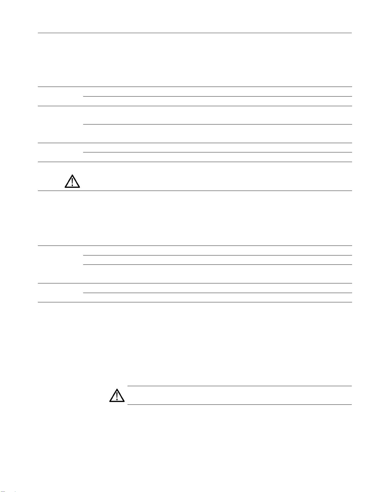
sh Default Setup.
4. Pu
MSO2000B and DPO2000B Installation and Safety Instructions 19
Power-On and Power-Off Procedure
5. Push Autoset
5Vat1kHz.
NOTE. For best perform ance, it is recommended that you set the Vertical scale to
1V.
If the signal appears but is misshapen, perform the procedures for
compens
If no signal appears, rerun the procedure. If this does not remedy the situation,
have th
. The screen should now display a square wave, approximately
ating the probe. (See page 20.)
e oscilloscope serviced by qualified service personnel.
Compensating a P assive Voltage Probe
Whene
compensate the probe to match it to the corresponding oscilloscope input channel.
ver you attach a passive voltage probe for the first time to any input channel,
operly compensate your passive p robe:
To pr
1. Follow the steps for the functional check. (See page 19.)
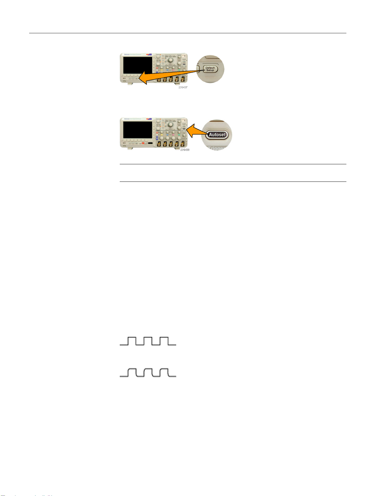
2. Check the shape of the displayed waveform to determine if your probe is
properly compensated.
Figure 3: Properly compensated
Figure 4: Under compensated
20 MSO2000B and DPO2000B Installation and Safety Instructions
Power-On and Power-Off Procedure
Quick Tips
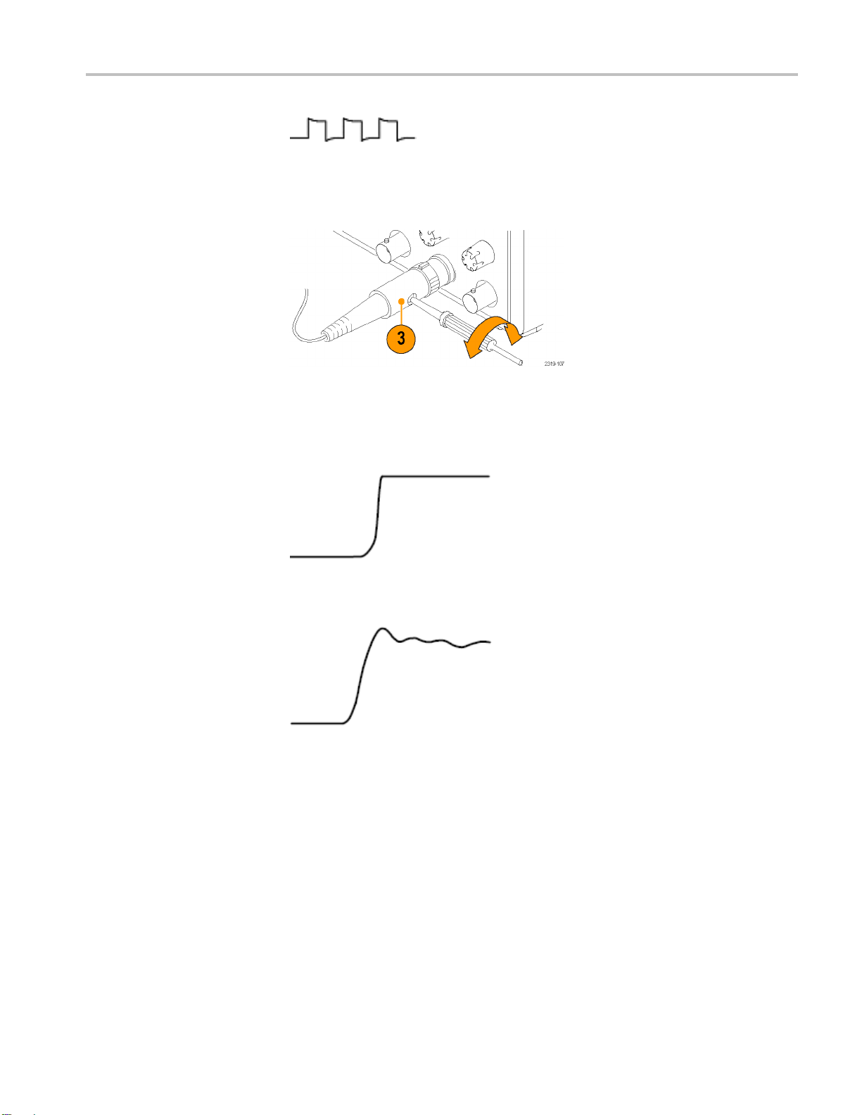
Figure 5: Over
3. If necessary
Use the shortest possible ground lead and signal path to minimize probe-induced
ringing and distortion on the measured signal.
compensated
, adjust your probe. Repeat as needed.
Figure 6: Signal with a short ground lead
Figure 7: Signal with a long ground lead
Application Module Free Trial
A 30-day free trial is available f or all application modules not installed in your
oscilloscope. The trial period begins when you power on the oscilloscope for
the first time.
After 30 days, you must purchase the module if you want to continue using the
application. To see the date when your free trial period expires, push the front
panel Utility button, push the lower-bezel Utility Page button, use multipurpose
knob a to select Config, and push the lower-bezel About button.
MSO2000B and DPO2000B Installation and Safety Instructions 21
Power-On and Power-Off Procedure
Upgrading Firmware
To upgrade the firmware of the oscilloscope:
1. Open up a Web browser and go to www.tektronix.com/software. Proceed to
the software finder. Download the latest firmware for your oscilloscope on
your PC.
Unzip the files and copy the firmware.img file into the root folder of a USB
flash drive.
2. Power off your oscilloscope.
3. Insert the USB flash drive into the front-panel USB port on your oscilloscope.
4. Power on the oscilloscope. The oscilloscop
installs the replacement firmware.
If the oscilloscope does not install the firmware, rerun the procedure. If
the problem continues, try a different model of USB flash drive. Finally, if
needed, contact qualified service personnel.
NOTE. Do not power off the oscilloscope or remove the USB flash drive until the
scope finishes installing the firmware.
oscillo
5. Power off the oscilloscope and remove the USB flash drive.
6. Power on the oscilloscope.
7. Push Utility.
8. Push Utility Page.
9. Turn multipurpose knob a and select Config.
10. Push About. The oscilloscope displays the firmware version number.
e automatically recognizes and
11. Confirm that the version number matches that of the new firmware.
NOTE. For more information on updating the firmware, refer to the electronic
(PDF) MSO/DPO2000B User Manual.
22 MSO2000B and DPO2000B Installation and Safety Instructions

Power-On and Power-Off Procedure
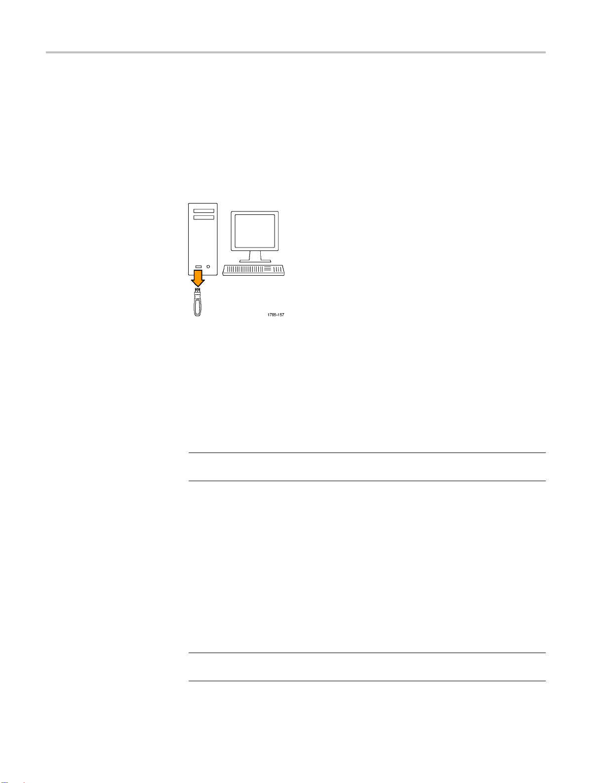
Connecting Yo
ur Oscilloscope to a Computer
You m ay want to document your work for future reference. Instead of saving
screen images and waveform data to a USB flash drive and generating a report
later, you ma
remote PC for analysis. You may also want to control an oscilloscope at a remote
location from your computer.
Two ways to connect your oscilloscope to a computer are through the VISA
(Virtual Instrument Software Architecture) drivers and the e*Scope Web-enabled
tools. Use VISA to communicate with your oscilloscope from y our computer
through a software application. Use e*Scope to communicate with your
oscilloscope through a Web browser.
NOTE. Fo
including instructions on how to save screen images and waveform data, refer to
the electronic (PDF) MSO/DPO2000B User Manual.
y want to get a copy of the image or waveform data directly from a
r more information on connecting your oscilloscope to a computer,
MSO2000B and DPO2000B Installation and Safety Instructions 23
Getting Acquainted with the Oscilloscope
Getting Acqua
inted with the Oscilloscope
Front-Panel Menus and Controls
The front pa
Use the menu buttons to access more specialized functions.
Using the Menu System
To use the menu system:
1. Push a front-panel menu button to display the m enu that you want to use.
nel has buttons and controls for the functions that you use most often.
24 MSO2000B and DPO2000B Installation and Safety Instructions

Getting Acquainted with the Oscilloscope
2. Push a lower-be
turn multipurpose knob a to select the desired choice. If a pop-up menu
appears, press the button again to select the desired choice.
3. Push a side-bezel button to choose a side-bezel menu item.
zel button to select a menu item. If a pop-out menu appears,
If the menu item contains more than one choice, push the side-bezel button
repeatedly to cycle through the choices.
If a pop-out menu appears, turn multipurpose knob a to select the desired
choice.
MSO2000B and DPO2000B Installation and Safety Instructions 25

Getting Acquainted with the Oscilloscope
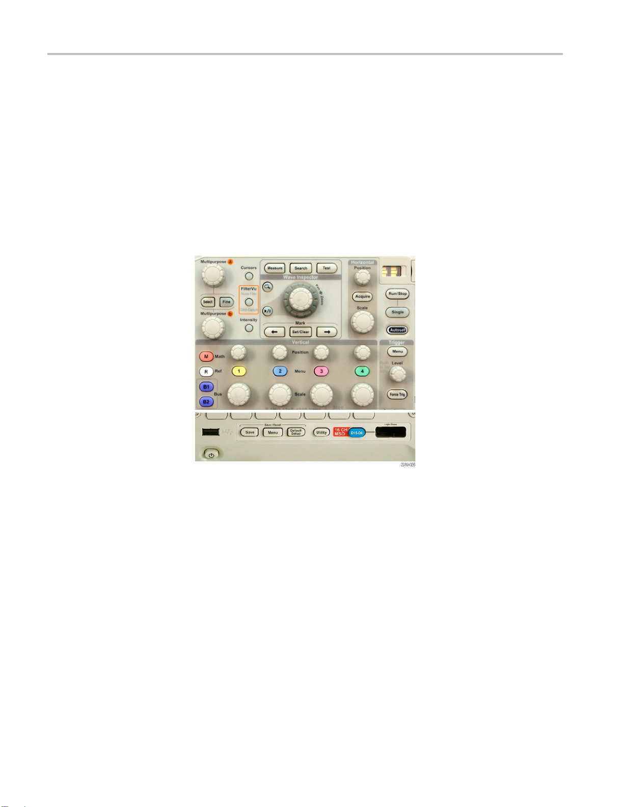
Using the Menu Buttons
Use the menu but
tons to perform many functions in the oscilloscope.
1. Measure. Pushtoperformautomatedmeasurements on waveforms or
to configure cursors.
2. Search. Push to search through an acquisition for user-defined events/criteria.
3. Test. Push to activate advanced or application-specific testing features.
4. Acquire. Push to set the acquisition mode and adjust the record length.
5. Autoset. Push to perform an automatic setup of oscilloscope settings.
6. Trigg
er Menu. Push to specify trigger settings.
7. Utility. Push to activate the system utility functions, such as selecting a
uage or setting the date/time.
lang
8. Save / Recall Menu. Push to save and recall setups, waveforms, and screen
es to internal memory, or a USB flash drive.
imag
9. Channel 1, 2, 3,or4Menu. Push to set vertical parameters for input
eforms and to display or remove the corresponding waveform from the
wav
display.
10.B1
or B2.Pushtodefine and display a serial bus if you have the appropriate
module application keys. The DPO2AUTO module s upports CAN and LIN
buses. The DPO2EMBD module supports I
2
C and SPI. The DPO2COMP
module supports RS-232, RS-422, RS-485, and UART buses.
Parallel bus support is available on MSO2000B products.
Also, push the B1 or B2 button to display or remove the corresponding bus
from the display.
26 MSO2000B and DPO2000B Installation and Safety Instructions

Getting Acquainted with the Oscilloscope
Using Other Controls
11. R.Pushtomanag
each reference waveform from the display.
12. M. Push to manage the math waveform, including the display or removal of
the math waveform from the display.
These buttons and knobs control waveforms, cursors, a
1. Turn the upper multipurpose knob a, when activated, to move a cursor, to set a
numerical parameter value for a menu item, or to select from a pop-out list of
choices. Push the Fine button to toggle between coarse and fine adjustment.
e reference waveforms, including the display or removal of
nd other data input.
Screen icons tell you when a or b are active.
2. Cursors. Push once to activate the two vertical cursors. Push again to turn on
the two vertical and two horizontal cursors. Push again to turn off all cursors.
When the cursors are on, you can turn the multipurpose knobs to control
their position.
3. Select. Push to activate special functions.
For example, when using the two vertical cursors (and no horizontal ones are
visible), you can push this button to link or unlink the cursors. When the two
vertical and two horizontal cursors are both visible, you can push this button
to make either the vertical cursors or the horizontal cursors active.
4. FilterVu.Pushtofilter unwanted noise from your signal and still capture
glitches.
5. Fine. Push to toggle between making coarse and fine adjustments with the
vertical and horizontal position knobs, the trigger level knob, and many
operations of multipurpose knobs a and b
6. Intensity. Push to enable multipurpose knob a to control waveform display
intensity and knob b to control graticule intensity.
7. Turn the lower multipurpose knob b, when activated, to move a cursor or set a
numerical parameter value for a menu item. Push Fine to make adjustments
more slowly.
MSO2000B and DPO2000B Installation and Safety Instructions 27

Getting Acquainted with the Oscilloscope
8. Zoom button. Push to activate zoom mode.
9. Pan (outer knob). Turn to scroll the zoom window through the acquired
waveform.
10. Zoom (inner knob). Turn to control the zoom factor. Turning it clockwise
zooms in further. Turning it counterclockwise zooms out.
11. Play-pause button. Push to start or stop the automatic panning of a
waveform. Control the speed a nd direction w ith the pan knob.
12. ← Prev. Push to jump to the previous waveform mark.
13. Set/C
14. → Next. Push to jump to the next waveform mark.
15. Horizontal Position. Turn to adjust the trigger point location relative to the
acquired waveforms. Push Fine to make smaller adjustments.
16. Horizontal Scale. Turn to adjust the horizontal scale (time/division).
lear Mark. Push to establish or delete a waveform mark.
28 MSO2000B and DPO2000B Installation and Safety Instructions

Getting Acquainted with the Oscilloscope
17. Run/Stop. Push to start or stop acquisitions.
18. Single. Push to make a single acquisition.
19. Autoset. Push to automatically set the vertical, horizontal, and trigger
controls for a usable, stable display.
20. Trigger Level. Turn to adjust the trigger level.
Push Level to Set 50%. Push the Trigger level knob to set the trigger level to
the midpoint of the waveform.
21. Force Trig. Push to force an immediate trigger event.
22. Ver
23.1,
24.V
tical Position. Turn to adjust the vertical position of the corresponding
waveform. Push Fine to make smaller adjustments.
2, 3, 4 Menu. Push to display or remove the corresponding waveform
from the display and access the vertical menu.
ertical Scale. Turn to adjust the vertical scale factor of the corresponding
waveform (volts/division).
MSO2000B and DPO2000B Installation and Safety Instructions 29

Getting Acquainted with the Oscilloscope
25. Print. Push to print to a PictBridge printer.
26. Power sw
27. USB 2.0 Host port. Insert a USB peripheral to the oscilloscope, such as
akeybo
28. Save. Push to perform an immediate save operation. The save operation uses
the cu
29. Default Setup. Push to perform an immediate restore of the oscilloscope
to the
30. D15 - D0. Push to display or remove the digital channels from the display,
and t
31. Menu Off. Push to clear a displayed menu from the screen.
32. Waveform Only. Pushtoremovemenuandreadoutinformationfromthe
screen so the oscilloscope o nly displays the waveform or bus. Push a second
me to recall the previous menu and readout information.
ti
itch. Push to power on or off the oscilloscope.
ard or a flash drive.
rrent save parameters, as defined in the Save / Recall menu.
default settings.
o access the digital channel setup menu (MSO2000B series only).
30 MSO2000B and DPO2000B Installation and Safety Instructions

Getting Acquainted with the Oscilloscope
Front-Panel C
onnectors
1. Digital Probe Connector (MSO2000B series only).
2. Channel 1, 2,(3, 4). Channel inputs with TekVPI Versatile Probe Interface.
3. Aux In. Trigger level range is adjustable from +12.5 V to –12.5 V.
4. PROBE COMP. Square wave signal source to compensate probes
Side-Panel Connector
Output voltage: 0 V to 5 V, Frequency: 1 kHz
5. Groun
6. Application Module Slots.
d.
MSO2000B and DPO2000B Installation and Safety Instructions 31

Getting Acquainted with the Oscilloscope
Rear-Panel Connectors
1. TekVPI e xte rna
external power supply (Tektronix part number 119‑7465‑XX) w hen additional
power is needed for TekVPI probes.
1. LAN. Use the LAN (Ethernet) port (RJ-45 connector) to connect the
oscilloscope to a 10/100 Base-T local area network. The port is available on
the opti
2. Lock. Use to secure the oscilloscope and optional connectivitiy module.
3. Video Out. Use the Video Out port (DB-15 female connector) to show the
oscilloscope display on an external monitor or projector. The port is available
on the
onal connectivity module (DPO2CONN).
optional connectivity module (DPO2CONN).
l power supply connector. Use the connector for the TekVPI
4. USB 2.0 Device port. Use the USB 2.0 Full Speed Device port to connect
Bridge compatible printer, or for direct PC control of the oscilloscope
aPict
using USBTMC protocol.
NOTE. The cable connected from the USB 2.0 Device port to the host computer
must meet the USB2.0 specification for high speed operation when connected to
a high speed host controller.
5. Power input. Attach to an AC power line with integral safety ground.
32 MSO2000B and DPO2000B Installation and Safety Instructions

まえがき
まえがき
このマニュアルでは、次のオシロスコープのインストール方法と操作方法につ
いて説明します。
アクセサリと交換部品
スタンダード・アクセサリ
DPO2002B
DPO2014
MSO2002
MSO2014
型
B型
B型
B型
DPO2004B
DPO2022
MSO2004
MSO2022
型
B型
B型
B型
DPO2012B
DPO2024
MSO2012
MSO2024
型
B型
B型
B型
人体への損傷を避け、本製品や本製品に接続されている製品への損傷を
防止するための安全性に関する注意事項
本製品が適合している EMC 基準、安全基準、および環境基準
本製品を使用するための電圧、電力、および環境要件
設置手順
電源投入、電源遮断の手順
フロント・パネルとリア・パネルのコントロールとコネクタ
アクセサリ 説明 当社部品番号
DPO2000B シリーズおよび
MSO2000B シリーズ・オシロス
コープの設置と安全性に関す
る手順書
DPO2000B/MSO2000B シリー
ズ・オシロスコープ・マニュア
ルCD
Tektronix OpenChoice
Desktop PC Communications
CD
計量標準総合センターへのト
レーサビリティと、ISO9001 品
質システム登録を文書化した
校正証明書
安全性とコンプライアンスに関
する情報、ハードウェアの設置
手順および禁止事項(警告)に
ついて説明します。 英語版、簡
体字中国語版、日本語版が用
意されています。
MSO/DPO4000B シリーズ・マ
ニュアルの CD バージョンに
は、『プログラマ・マニュアル』と
『テクニカル・リファレンス』が含
まれています。
生産性向上、解析、および文書
作成用のソフトウェアです。
071-3078-XX
063-4472‑XX
063-4402‑XX
——
MSO2000B and DPO2000B Installation and Safety Instructions 33

まえがき
スタンダード・アクセサリ, (続き)
アクセサリ 説明 当社部品番号
フロント・パネル・オーバーレイ
フランス語(オプション L1 型)
イタリア語(オプション L2 型)
ドイツ語(オプション L3 型)
スペイン語(オプション L4 型)
日本語(オプション L5 型)
ポルトガル語(オプション L6 型)
簡体字中国語(オプション L7
型)
繁体中国語(オプション L8 型)
韓国語(オプション L9 型)
ロシア語(オプション L10 型)
335-2020-00
335-2021-00
335-2022-00
335-2023-00
335-2024-00
335-2025-00
335-2026-00
335-2027-00
335-2028-00
335-2029-00
DPO2000B シリーズおよび
MSO2000B シリーズ用: プ
ローブ
MSO2000B シリーズ: デジタ
ル・プローブ
MSO2000B シリーズ: アクセ
サリ・ポーチ
5年保証
帯域 ≥ 100 MHz のモデル: 1
チャンネルに付き 200 MHz、
10X 受動電圧プローブ 1 本、入
力抵抗 10 MΩ
帯域 ≥ 100 MHz のモデル: 1
チャンネルに付き 100 MHz、
10X 受動電圧プローブ 1 本、入
力抵抗 10 MΩ
16 チャンネル・デジタル・プロー
ブ(1 本)
プローブやその他のアクセサリ
を持ち運ぶためのポーチ(ハン
ドルに取り付け)
詳細については、この電子版
ユーザ・マニュアル(PDF)冒頭
の「保証」をご覧ください
TPP0200 型
TPP0100 型
P6316 型
016-2008-00
——
34 MSO2000B and DPO2000B Installation and Safety Instructions

まえがき
スタンダード・アクセサリ, (続き)
アクセサリ 説明 当社部品番号
電源コード
北米(オプション A0 型)
汎用欧州(オプション A1 型)
英国(オプション A2 型)
オーストラリア(オプション A3
型)
スイス(オプション A5 型)
日本(オプション A6 型)
中国(オプション A10 型)
インド(オプション A11 型)
ブラジル(オプション A12 型)
電源コードおよび AC アダプタ
なし(オプション A99 型)
161-0348-00
161-0343-00
161-0344-00
161-0346-00
161-0347-00
161-0342-00
161-0341-00
161-0349-00
161-0356-00
——
MSO2000B and DPO2000B Installation and Safety Instructions 35

まえがき
オプショナル・アクセサリ
アクセサリ 説明 当社部品番号
DPO2EMBD 型
DPO2AUTO 型
DPO2COMP 型
DPO2CONN 型
NEX-HD2HEADER
エンベデッド・シリアル・トリガおよび解析モジュー
2
ル。I
Cシリアル・バスおよびSPIシリアル・バス上
でのパケット・レベル情
バス・デコード、検索ツールの使用、およびタイム
スタンプ情報付きパケット・デコード・テーブルの
表示が可能になります
自動シリアル・トリガおよび解析モジュール。CAN
および LIN シリアル
報によるトリガ、バス表示、バス・デコード、検索ツー
ルの使用、およびタイムスタンプ情報付きパケット・
デコード・テーブル
コンピュータ・トリガおよび解析モジュールにより、
RS-232、RS
アル・バスによるトリガ、検索ツールの使用、バス表
示、16 進/2 進/ASCII でのバス・デコード、およ
びタイムスタンプ
表示が可能になります。
接続モジュール。リモート・プログラミング用のイー
サネット・ポー
し、オシロスコープ画面を外部モニタに表示でき
るようにする。
Mictor コネクタから 0.1 インチのヘッダ・ピンにチャ
ンネルを転送するアダプタ。
-422、RS-485、および UART の各シリ
トおよびビデオ出力ポートを追加
報によるトリガ、バス表示、
。
・バス上でのパケット・レベル情
の表示が可能になります。
情報付きのデコード・テーブルの
DPO2EMBD 型
DPO2AUTO 型
DPO2COMP 型
DPO2CONN 型
NEX-HD2HEADER
MSO/D
ロスコープで使用する TekVPI プ
ローブ
注: これら
TekVPI 外部電源アダプタが必要
です。
TekVPI 外部電源アダプタ TekVPI プローブへの外部電源
TPA
注: このアダプタには上記の
TekVPI 外部電源アダプタが必要
です。
デス
電力測定デスキューおよび校正
アダプタ
TEK-USB-488 型アダプタ GPIB-USB アダプタ
ラックマウント・キット
運搬用ソフト・ケース オシロスコープの運搬用ケース ACD2000 型
PO2000B シリーズ・オシ
のプローブには下記の
-BNC
キュー・パルス発生器
当社の We
Oscilloscope Probe and Accessory Selector Tool
をご利用ください。
TekV
kVPI オシロスコープ・インタフェースを備えたデ
Te
スキュー・パルス発生器および信号源
TEK-DPG パルス発生器の出力を一連のテスト・ポ
ント接続に変換
イ
ックマウント用ブラケット
ラ
b サイト (www.tektronix.com)の
PI-TekProbe II BNC アダプタ
7465‑XX
119‑
-BNC
TPA
TEK-DPG
067-1686-00
EK-USB-488
T
RMD2000 型
36 MSO2000B and DPO2000B Installation and Safety Instructions

オプショナル・アクセサリ, (続き)
アクセサリ 説明 当社部品番号
運搬用ハード・ケース
DPO2000B/MSO2000B シリーズ・
オシロスコープ・サービス・マニュ
アル
DPO2000B/MSO2000B シリーズ・
オシロスコープ・アプリケーション・
モジュールのインストレーション
持ち運び用ハード・ケース。運搬用ソフト・ケース
(ACD2000)を使用する必要があります。
DPO2000B/MSO2000B シリーズ・オシロスコープ
に関するサービス情報。
DPO2000B/MSO2000B シリーズ・オシロスコープ
にアプリケーション・モジュールをインストールする
方法を説明します。
HCTEK4321
077-0737‑XX
071-2330-XX
マニュアル
以下の表に、本製品の関連マニュアルおよびそのメディアと参照先を示
します。 マニュアルのメディアには、冊子、CD-ROM、当社の Web サイト
(www.tektronix.com)の 3 種類があります。
まえがき
表5: 製品マニュアル
項目 内容 参照先
設置と安全性に関する手順書(本
マニュア
ユーザ・マニュアル
仕様および性能検査のテクニカル・
リフ
プログラマ・マニュアル 本器をリモート制御するためのコマ
サービス・マニュアル
ル)
ァレンス
安全性とコンプライアンスに関する
情報、ハ
び禁止事項(警告)について説明し
ます。 英語版、日本語版、簡体字
中国語版
操作方
します。 英語版、フランス語版、ド
イツ語版、イタリア語版、スペイン語
版、ポ
日本語版、韓国語版、簡体字中国
語版、および繁体字中国語版があ
りま
機器の仕様および性能チェック手
順に
ンドについて説明します。
調整、修理、部品交換について説
明します。
ードウェアの設置手順およ
の 3 種類があります。
法および用途について説明
ルトガル語版、ロシア語版、
す。
ついて説明します。
印刷マニュアル。PDF 版は
tektronix.com/manuals でも入
www.
手できます。
製品マ
www.tektronix.com/manuals でも入
手できます。
マニュアル CD。PDF 版は
製品
www.tektronix.com/manuals でも入
手できます。
製品マニュアル CD。PDF 版は
ww.tektronix.com/manuals でも入
w
手できます。
PDF 版 。
www.tektronix.com/manuals で入
手できます。
ニュアル CD。PDF 版は
MSO2000B and DPO2000B Installation and Safety Instructions 37

安全にご使用いただくために
安全にご使用いただくために
人体への損傷を避け、本製品や本製品に接続されている製品の破損を防止
するために、安全に関する次の注意事項をよくお読みください。
安全のために、指示に従って本製品を使用してください。
資格のあるサービス担当者以外は、保守点検手順を実行しないでください。
本製品をご使用の際に、より大きな他のシステムにアクセスしなければならな
い場合があります。 システムの操作に関する警告や注意事項については、他
製品のコンポーネントのマニュアルにある安全に関するセクションをお読みく
ださい。
発火や人体への損傷を
避けるには
適切な電源コードを使用してください: 本製品用に指定され、使用される国で
認定された電源コードのみを使用してください。
接続と切断の手順を守ってください: プローブとテスト・リードが電圧源に接続
されている間は接続または切断しないでください。
接続と切断の手順を守ってください: 被測定回路の電源を切ってから、電流
プローブの接続あるいは切断を行ってください。
本製品を接地してください: 本製品は、電源コードのグランド線を使用して接
地します。 感電を避けるため、グランド線をアースに接続する必要があります。
本製品の入出力端子に接続する前に、本製品が正しく接地されていることを
確認してください。
すべての端子の定格を守ってください: 火災や感電の危険を避けるために、
本器のすべての定格とマーキングに従ってください。 本製品に電源を接続す
る前に、定格の詳細について、製品マニュアルを参照してください。
プローブの基準リードは、グランドにのみ接続してください。
コモン端子を含むいかなる端子についても、その端子の定格の上限を超える
電位を加えないでください。
電源の切断: 電源コードの取り外しによって主電源が切り離されます。 電源
コードをさえぎらないでください。コードには常にアクセスできることが必要です。
カバーを外した状態では使用しないでください: カバーやパネルを外した状
態で本製品を動作させないでください。
故障の疑いがあるときは使用しないでください: 本製品に故障の疑いがある
場合、資格を有するサー ビス担当者に検査を依頼してください。
回路の露出を避けてください: 電源が投入されているときに、露出した接続部
分や部品に触れないでください。
38 MSO2000B and DPO2000B Installation and Safety Instructions

安全にご使用いただくために
本マニュアル内の用語
本製品に関する記号と用
語
湿気の多いところでは使用し
爆発しやすい環境では動作させないでください:
製品の表面を清潔で乾燥した状態に保ってください:
充分な換気を確保してく
分な換気を確保してください。
本マニュアルでは次の用語を使用します。
警告: 人体や生命に危害をおよぼすおそれのある状態や行為を示します。
注意: 本製品やその他の接続機器に損害を与えるおそれのある状態や行為
を示します。
本製品では、次の用語を使用します。
DANGER:直ちに人体や生命に危険をおよぼす可能性があることを示しま
す。
ないでください:
ださい: ユーザ・マニュアルの設置手順を参照し、充
WARNING:人体や生命に危険をおよぼす可能性があることを示します。
CAUTION:本製品を含む周辺機器に損傷を与える可能性があることを示
します。
本製品では、次の記号を使用します。
MSO2000B and DPO2000B Installation and Safety Instructions 39

適合性に関する情報
適合性に関する情報
EMC 適合性
EC 適合宣言 - EMC
このセクションでは、本器
が適合している EMC 基準、安全基準、および環境
基準について説明します。
指令 2004/108/EC 電磁環境両立性に適合します。 『Official Journal of the
European Communities』に記載の以下の基準に準拠します。
EN 61326-1:2006、EN 61326-2-1:2006: 測定、制御、および実験用途の電子
機器を対象とする EMC 基準
123
CISPR 11:2003:グループ 1、クラス A、放射および伝導エミッション
IEC 61000-4-2:2001:静電気放電イミュニティ
IEC 61000-4-3:2002:RF 電磁界イミュニティ
4
IEC 61000-4-4:2004:ファスト・トランジェント/バースト・イミュニティ
IEC 61000-4-5:2001:電源サージ・イミュニティ
IEC 61000-4-6:2003:伝導 RF イミュニティ
IEC 61000-4-11:2004:電圧低下と停電イミュニティ
5
6
EN 61000-3-2:2006: AC 電源高調波エミッション
EN 61000-3-3:1995: 電圧の変化、変動、およびフリッカ
欧州域内連絡先:
Tektronix UK, Ltd.
Western Peninsula
Western Road
Bracknell, RG12 1RF
United Kingdom
United Kingdom
1
本製品は住居区域以外での使用を目的としたものです。 住居区域で使用すると、電磁干
渉の原因となることがあります。
2
本製品をテスト対象に接続した状態では、この規格が要求するレベルを超えるエミッショ
ンが発生する可能性があります。
3
ここに挙げた各種 EMC 規格に確実に準拠するには、高品質なシールドを持つインタフェー
ス・ケーブルが必要です。
4
IEC 61000-4-3 テストの条件下では、4 div p-p 未満のトレース・ブルームが誘導さ れる場
合があります。
5
IEC 61000-4-6 テストの条件下では、1 div p-p 未満のトレース・ブルームが誘導さ れる場
合があります。
40 MSO2000B and DPO2000B Installation and Safety Instructions

適合性に関する情報
オーストラリア/ニュー
ジーランド適合宣言
-EMC
6
70%/25 サイクルの電圧
能基準 C を適用します(IEC 61000-4-11)。
7
低下および 0%/250 サイクル瞬断の各テスト・ レベルにおいて、性
ACMA に従い、次の規格に準拠することで Radiocommunications Act の EMC
条項に適合しています。
CISPR 11:2003:グループ 1、クラス A、放射および伝導エミッション
(EN61326-1:2006 および EN61326-2-1:2006 に準拠)
オーストラリア/ニュージーランドの連絡先:
Baker & McK
enzie
Level 27, AMP Centre
50 Bridge Street
Sydney NSW 2000, Australia
MSO2000B and DPO2000B Installation and Safety Instructions 41

適合性に関する情報
安全性
EC 適合宣言 - 低電圧指
令
米国の国家認定試験機
関のリスト
カナダ規格
その他の基準に
対する
適合性
機器の種類
『Official Journal of the European Communities』に記載の以下の基準に準拠し
ます。
低電圧指令 2006/95/EC
EN 61010-1: 2001:測定、制御および実験用途の電子装置に対する安全
基準。
UL 61010-1:2004 年第 2 版:電子計測機器および試験用機器の標準規
格。
CAN/CSA-C22.2 No. 61010-1:2004:測定、制御、および実験用途の電子
装置に対する安全基準、 第 1 部。
IEC 61010-1: 2001:測定、制御、および実験用途の電子装置に対する安
全基準。
テスト機器および計測機器。
安全クラス
汚染度について
クラス 1 - アース付き製品。
製品内部およびその周辺で発生する可能性がある汚染度の尺度です。 通常、
製品の内部
されている環境でのみ使用してください。
汚染度 1
このカテゴリの製品は、通常、被包性、密封性のあるものか、クリーン・ルー
ムでの使用を想定したものです。
汚染度 2:通常、乾燥した非導電性の汚染のみが発生します。 ただし、結
露によって一時的な導電性が発生することもまれにあります。 これは、標
準的なオフィスや家庭内の環境に相当します。 一時的な結露は製品非動
作時のみ発生します。
汚染度 3:伝導性のある汚染、または通常は乾燥して導電性を持たないが
結露時に導電性を帯びる汚染。 これらは、温度、湿度のいずれも管理さ
れていない屋内環境に相当します。 日光や雨、風に対する直接の曝露か
らは保護されている領域です。
汚染度 4:導電性のある塵、雨、または雪により持続的に導電性が生じて
いる汚染。 これは一般的な屋外環境に相当します。
環境は外部環境と同じとみなされます。 製品は、その製品に指定
:汚染なし、または乾燥した非導電性の汚染のみが発生します。
42 MSO2000B and DPO2000B Installation and Safety Instructions

適合性に関する情報
汚染度
測定カテゴリ/過電圧カ
テゴリの記述
過電圧カテゴリ
汚染度 2(IEC 61010
す。
本製品の各端子には異な
ります。 各測定カテゴリは次のように定義されています。
測定カテゴリ IV。低
測定カテゴリ III。
測定カテゴリ II。低電圧電源に直接接続した回路で実施する測定用。
測定カテゴリ I。AC 電源に直接接続していない回路で実施する測定用。
過電圧カテゴリ II(IEC 61010-1 の定義による)
-1 の定義による)。 注: 屋内使用のみについての評価で
る測定(過電圧)カテゴリが指定されている場合があ
電圧電源を使用して実施する測定用。
建築物の屋内配線で実施する測定用。
MSO2000B and DPO2000B Installation and Safety Instructions 43

適合性に関する情報
環境への配慮
このセクションでは本製品が環境におよぼす影響について説明します。
使用済み製品の処理方
法
有害物質に関する規制
機器またはコンポーネントをリサイクルする際には、次のガイドラインを順守し
てください。
機器のリサイクル: 本
品には環境または人体に有害となる可能性のある物質が含まれているため、
製品を廃棄する際には適切に処理する必要があります。 有害物質の放出を
防ぎ、天然資源の使用を減らすため、本製品の部材の再利用とリサイクルの
徹底にご協力ください。
このマークは、本
リに関する指令 2002/96/EC および 2006/66/EC に基づき、EU の
諸要件に準拠していることを示しています。 リサイクル方法について
は、当社の We
参照してください。
水銀に関する通知: 本製品に使用されている LCD バックライト・ランプには、
水銀が含まれています。 廃棄にあたっては、環境への配慮が必要です。 廃棄
およびリサイクルに関しては、お住まいの地域の所轄官庁にお尋ねください。
この製品は Monitoring and Control(監視および制御)装置に分類され、
2002/95/EC RoHS Directive(電気・電子機器含有特定危険物質使用制限
指令)の適用範囲外です。
製品の製造には天然資源が使用されています。 本製
製品が WEEE(廃棄電気・電子機器)およびバッテ
b サイト(www.tektronix.com)のサービス・セクションを
44 MSO2000B and DPO2000B Installation and Safety Instructions

動作の要件
動作の要件
このセクションでは、製品を安全かつ正しく使用するために把握しておくべき
仕様について説明します。 詳細については、MSO/DPO2000B シリーズ・テク
ニカル・リファレンスの
製品仕様の項を参照してください。
DPO2000B/MSO2000B
シリーズのオシロスコー
プ
電源入力電圧: 100 V ~ 240 V ±10%
入力電源周波数:
50/60 Hz(100 V ~ 240 V)
400 Hz、115 V
消費電力: 80 W(最大)
入力電圧(信号電圧と基準電圧の間): 300 V
測定カテゴリ II:低電圧電源に直接接続した回路で実施する測定用。
RMS
CAT II
図 8: MSO2000B シリーズ
図 9: DPO2000B シリーズ
MSO2000B and DPO2000B Installation and Safety Instructions 45

動作の要件
TPP0100 型 ま た は
TPP0200 型受動プロー
ブ
P6316 型デジタル・プロー
ブを使用した MSO2000B
シリーズ・オシロスコープ
シングルエンド電圧プローブ
インストレーション・カテゴリ II:低電圧電源に直接接続した回路で実施する測定用。
温度:
動作時: –10 ~ +55 ℃(+14 ~ +131 ゚F)
非動作時: –51 ~ +71 ℃ (-60 ~ +160 ゚F)
汚染度: 2、ただし、屋内使用のみ
湿度: 相対湿度 5% ~
スレッショルド確度: ±(100 mV + スレッショルドの 3%)
スレッショルド範囲: ±20 V
プローブへの最大非破壊入力信号: ±40 V ピーク
最小信号スイング: 500 mV
入力抵抗: 101 kΩ
入力キャパシタンス: 8.0 pF
温度:
動作時: 0 ~ +50 ℃(+32 ~ +122 ゚F)
非動作時: –20 ~ +60 ℃(-4 ~ +140 ゚F)
(グランド基準): 300 V
95%
p-p
CAT II 安全基準
RMS
高度:
動作時: 最高 3,000 m(9,843 フィート)
非動作時: 最高 12,000 m(39,370 フィート)
汚染度: 2、ただし、屋内使用のみ
湿度:
相対湿度 5 ~ 95%
46 MSO2000B and DPO2000B Installation and Safety Instructions

電気定格
電源要件
動作の要件
電源コネクタ
ヒュー
ズ
バッテリ
本製品の電源要件
アース近傍電位の 1 本の通電導体(中性線)を持つ単相電源。
注: 2本の通電
相間など)は、電源として推奨されません。
AC 電源周波数: 50 または 60 Hz
AC 電源電
警告: 発火および感電のリスクを減らすため、主電源の電圧変動が動作電圧
レンジの 10% を超えていないことを確認してください。
ライン側のみ、過電流保護のためにヒューズが付けられています。 この内蔵
ヒューズはユーザによる交換を想定したものではありません。 ヒューズの交換
はしないでください。 ヒューズが飛んでいると思われる場合は、認定サービス・
ターに機器を返送して修理を受けてください。
セン
にユーザ交換可能なバッテリはありません。
本器
は次のとおりです。
導体が接地に対して通電状態のシステム(多相システムでの
圧: 100 ~ 240 V
AC
入力定格
表 6: 最大入力電圧
入力 定格
フロント・パネルの BNC コネクタ
P6316 型プローブの入力端(機
器の入力でなく)
MSO2000B and DPO2000B Installation and Safety Instructions 47
300 V RMS、測定カテゴリ II、4 MHz を超えると 200 MHz で 6 V RMS まで低下。
±40 V ピーク

動作の要件
環境要件
表 7: 環境仕様
特性 説明
温度
湿度
高度
冷却
動作時
非動作時
動作時
非動作時
動作時 3,000 m(9
非動作時 12,000 m(39,370 フィート)
50 mm(2 インチ)
0~+50℃
-20 ~ +60 ℃
高温: 40 ~ 50 ℃において、相対湿度 10 ~ 60%
低温: 0 ~ 40 ℃において、相対湿度 10 ~ 90%
高温: 40 ~ 60 ℃において、相対湿度 5 ~ 60%
低温: 0 ~ 40 ℃において、相対湿度 5 ~ 90%
注意: 適切に冷
ください。
物理仕様
表 8: 物理仕様
特性 説明
寸法
高さ
175 mm(6.885 インチ)、脚部を含みハンドルを含まず
,842 フィート)
却するため、オシロスコープの両側および背面を他の物でふさがないようにして
重量
クリーニング
幅
奥行き
本体 3.6 kg(スタンドアローン型オシロスコープの場合)
輸送
377 mm(14.85 インチ)
134mm(5.3インチ)、脚部からノブ前面まで
139 mm(5.47 インチ)、脚部からフロント・カバーの前面まで
動作状況に応じた頻度でオシロスコープとプローブを検査してください。 外部
表面の汚れを落とすには、次のようにします。
1. 乾いた柔らかい布で、オシロスコープとプローブの表面についた塵を落とし
ます。 ガラスのディスプレイ・フィルタを傷つけないように注意してください。
2. 水で湿らせた柔らかい布を使用して、オシロスコープの汚れを拭き取りま
す。 75% イソプロピル・アルコール水溶剤を使用すると汚れがよく落ちます。
注意: 研磨剤や化学洗浄剤は使用しないでください。機器やプローブの表
面が損傷する可能性があります。
48 MSO2000B and DPO2000B Installation and Safety Instructions

インストール手順
インストール手順
プローブの接続
オシロスコープとプローブは次の方法で接続できます。
1. Tektron
これらのプローブは、画面上のメニューおよびリモート設定可能な機能を
通して、オシロ
ントロールは、ATE(自動テスト環境)などで、システムのプローブ・パラメー
タをプリセットする場合に役立ちます。
ix 汎用プローブ・インタフェース(TekVPI)
スコープとの双方向通信をサポートしています。 リモート・コ
注: MSO2000B シリーズおよび DPO2000B シリーズ・オシロスコープではさまざ
まなプローブを使用できます。詳細については、当社 Web サイトの Oscilloscope
Probe and Accessory Selector Tool をご利用ください。
2. TPA-BNC 型\アダプタ
プロー
プに取り込むなど、Tek Probe II プローブの機能を使用できるようになりま
す。
注: TekVPI プローブと TPA-BNC アダプタを使用するには、TekVPI 外部電
源アダプタ(当社部品番号 119‑7465‑XX)をサイド・パネルの Probe Power(プ
ローブ電源)コネクタに接続します。
3. 通常の BNC インタフェース
ブに電力を供給したり、スケーリング情報や単位情報をオシロスコー
MSO2000B and DPO2000B Installation and Safety Instructions 49

インストール手順
TekProbe の機能を使
プに送るプローブもあれば、 波形信号のみを送信し、オシロスコープとの
間で通信を行わないプローブもあります。
4. デジタル・プローブ・インタフェース(MSO2000B シリーズのみ)
P6316 型プローブ
提供します。
DPO2000B シリ
なプローブを使用できます。詳細については www.tektronix.com を参照してく
ださい。
ーズおよび MSO2000B シリーズのオシロスコープではさまざま
用して、波形信号やスケーリング情報をオシロスコー
は、16 チャンネルのデジタル(オン/オフ状態)情報を
50 MSO2000B and DPO2000B Installation and Safety Instructions

電源投入、電源切断の手順
本製品はアース近傍電位の中性線を持つ単相電源で動作します。 ライン側
には、過電流保護のためにヒューズが付けられています。 安全な操作のため
には、電源コード内の接
地線を通じた保護用のグランド接続が不可欠です。
電源投入、電源切断の手順
電源の投入
電源の切断
1. 付属の電源コードをリア・パネルの電源コネクタに接続します。
2. フロント・パネルの電源ボタンを押して、電源を投入します。
注: フロント・パネルのスタンバイ・ボタンを押しても AC 電源は切断できませ
ん。 AC 電源を切断するには、リア・パネルの電源コードを抜く必要があります。
1. フロント・パネルの電源ボタンを押して、電源を切断します。
2. 電源を完全に切断するには、リア・パネルから電源コードを引き抜きます。
MSO2000B and DPO2000B Installation and Safety Instructions 51

電源投入、電源切断の手順
機能チェック
簡単な機能チェックを実行して、オシロスコープが正常に動作しているか確認
します。
1. 「オシロスコープの電源の投入」の説明に従って、オシロスコープの電源
ケーブルを接続します (51 ページ 「電源投入、電源切断の手順」 参照)。
2. オシロスコープの電源を投入します。
3. TPP0100 型または TPP0200 の適切なプローブ・チップとリファレンス・リー
ドを、オシロスコープの PROBE COMP(プローブ補正)コネクタに接続しま
す。
4. Default Setup を押します。
52 MSO2000B and DPO2000B Installation and Safety Instructions

電源投入、電源切断の手順
5. Autoset(オート
が画面に表示されます。
注: 最適なパフォーマンスを実現するため、垂直軸スケールを 1 V に設定す
ることをお勧めします。
信号は表示されているのに形状がゆがんでいる場合は、プローブの補正
手順を実行します (53 ページ参照)。
信号が表示されない場合は、同じ手順を再度実行します。 それでも問題
が解消されない場合は、資格のあるサービス担当者にオシロスコープの修
理を依頼してください。
受動電圧プローブの補正
セット)を押します。 振幅約 5 V、周波数 1 kHz の方形波
受動電圧プローブを初めて入力チャンネルに取り付ける場合は、必ずプロー
ブを補正して、対応するオシロスコープの入力チャンネルに適合させるように
します。
受動プローブを正しく補正するには、次の手順を実行します。
1. 次の手順に従って、機能チェックを実施します (52 ページ参照)。
2. 表示される波形の形状をチェックして、プローブが正しく補正されているか
確認します。
図 10: 適切な補正
図 11: 補正不足
MSO2000B and DPO2000B Installation and Safety Instructions 53

電源投入、電源切断の手順
図 12: 過度の補正
3. 必要に応じて、プローブを調整します。 必要なだけ調整を繰り返します。
ヒント グランド・リードと信号パスを可能な限り短くして、プローブに起因する測定信
号上のリンギングおよび歪を最小限にします。
図 13: 短いグランド・リード使用時の信号
図 14: 長いグランド・リード使用時の信号
アプリケーション・モジュールの無料トライアル
オシロスコープにインストールされていないアプリケーション・モジュールは、ど
れも 30 日間無料で試用できます。 トライアル期間は、初めてオシロスコープ
の電源をオンにした時点から起算されます。
30 日経過後も継続使用するには、モジュールをご購入いただく必要がありま
す。 トライアル期間の終了日を確認するには、フロント・パネルの Utility ボタ
ンを押して、下のベゼルの Utility Page(ユーティリティ・ページ)ボタンを押し、
汎用ノブ a を使用して Config(設定)を選択し、下のベゼルの About(バージョ
ン情報)ボタンを押します。
54 MSO2000B and DPO2000B Installation and Safety Instructions

ファームウェアのアップグレード
電源投入、電源切断の手順
オシロスコープのファーム
します。
1. Web ブラウザを起動し
トウェア・ファインダを実行します。 ご使用のオシロスコープ用の最新ファー
ムウェアを PC にダウンロードします。
ダウンロードしたファイルを解凍し、firmware.img ファイルを USB フラッシュ・
ドライブのルート・フォルダにコピーします。
2. オシロスコープの電源を切ります。
3. USB フラッシュ・ドライブをオシロスコープのフロント・パネルにある USB
ポートに挿入します。
ウェアをアップグレードするには、次の手順を実行
て、www.tektronix.com/software にアクセスし、 ソフ
4. オシロスコープの電源を投入します。 アップグレード用ファームウェアが自
動的に認識され、インストールされます。
ファームウェアのインストールが開始されない場合は、同じ手順を再度実
行します。 手順を繰り返してもインストールできない場合は、別の USB フ
ュ・ドライブを試してください。 それでも問題が解決しない場合は、
ラッシ
当社営業所にご連絡ください。
注: ファームウェアのインストールが完了するまで、オシロスコープの電源を
切ったり、USB フラッシュ・ドライブを取り外したりしないでください。
5. オシロスコープの電源を切って、USB フラッシュ・ドライブを取り外します。
6. オシロスコープの電源を投入します。
7. Utility を押します。
8. Utility Page(ユーティリティ ページ)を押します。
9. 汎用ノブ a を回して、Config(設定)を選択します。
MSO2000B and DPO2000B Installation and Safety Instructions 55

電源投入、電源切断の手順
10. About(バージョン情報
バージョンが表示されます。
11. バージョン番号が、新しい
します。
注: ファームウェアの更新の詳細については、MSO/DPO2000B ユーザ・マ
ニュアル(PDF)を参照してください。
オシロスコープとコンピュータの接続
作業データを文書化しておけば、今後の操作で役立てることができます。 ス
クリーン・イメー
そこからレポートを生成するという手間は不要です。イメージや波形データをリ
モート PC へ直接取り込んで、解析することができます。 離れた場所にあるコ
ンピュータからオシロスコープを制御することもできます。
オシロスコープをコンピュータに接続する方法は 2 つあります。1 つは VISA
(Virtual Instrument Software Architecture)ドライバを経由する方法、もう 1 つ
は Web 対応の e*Scope ツールを使用する方法です。 VISA を使用すると、コ
ンピュータからソフトウェア・アプリケーションを介してオシロスコープと通信で
きます。 e
できます。
ジや波形データを USB フラッシュ・ドライブにいったん保存し、
*Scope を使用すると、Web ブラウザを介してオシロスコープと通信
)を押します。 オシロスコープにファームウェアの
ファームウェアの番号に一致していることを確認
注: オシロスコープをコンピュータに接続するための詳細については、
MSO/DPO2000B ユーザ・マニュアル(PDF)を参照してください。スクリーン・イ
メージと波形データの保存方法についても説明があります。
56 MSO2000B and DPO2000B Installation and Safety Instructions

オシロスコープの概要
フロント・パネル・メニューとコントロール
フロント・パネルには、頻繁に使用する機能に対するボタンとコントロールが備
えられています。 メニュー・ボタンを使用すると、さらに高度な機能にアクセス
できます。
オシロスコープの概要
メニュー・システムの使用
メニュー・システムを使用するには、次の手順を実行します。
1. フロント・パネルのメニュー・ボタンを押して、使用するメニューを表示しま
す。
MSO2000B and DPO2000B Installation and Safety Instructions 57

オシロスコープの概要
2. 下のベゼル・ボタンを押して
ニューが表示された場合は、汎用ノブ a を回して目的の項目を選択しま
す。 さらにポップアップ・メニューが表示された場合は、ボタンを再度押し
て、目的の項目を選択します。
3. 側面ベゼル・ボタンを押して、ベゼル・メニュー項目を選択します。
、メニュー項目を選択します。 ポップアウト・メ
メニュー・ボタンの使用
メニュー項目が複数の選択肢を含む場合は、側面ベゼル・ボタンを繰り返
し押して、選択肢を繰り返し表示させます。
ポップアウト・メニューが表示された場合は、汎用ノブ a を回して目的の項
目を選択します。
メニュー・ボタンを使用すると、オシロスコープのさまざまな機能が実行できま
す。
58 MSO2000B and DPO2000B Installation and Safety Instructions

オシロスコープの概要
1. Measure(波形測定)。 このボタンを押すと、波形の自動測定を実行する
か、またはカーソルが設定できます。
2. Search(検索)。 このボタンを押すと、取り込んだ波形を調べてユーザ定
義のイベント/基準の状況を確認することができます。
3. Test(テスト)。 このボタンを押すと、高度なあるいはアプリケーション固有
のテスト機能が起動します。
4. Acquire(波形取込)。 このボタンを押すと、アクイジション・モードを設定
してレコード長を調節することができます。
5. Autoset(オートセット)。 このボタンを押すと、オシロスコープの設定を自
動的にセットアップできます。
6. Trigger(トリガ)の Menu(メニュー)。 このボタンを押すと、トリガ設定が指
定できます。
7. Utility。 このボタンを押すと、言語の選択または日時の設定などのシステ
ム・ユーティリティ機能が起動します。
8. Save/Recall Menu。 このボタンを押すと、設定、波形、スクリーン・イメー
ジを内部メモリまたは USB フラッシュ・ドライブに保存することや、これらの
データを呼び出すことができます。
9. チャンネル 1、2、3、または 4 の Menu(メニュー)。 これらのボタンを押す
と、入力波形の垂直軸パラメータを設定したり、対応する波形をディスプレ
イに表示したり、ディスプレイから消去したりできます。
10. B1 または B2。 適切なモジュール・アプリケーション・キーがある場合は、
これらのボタンを押すことで、シリアル・バスを定義または表示することがで
きます。 DPO2AUTO 型モジュールは CAN バスと LIN バスをサポートして
います。 DPO2EMBD 型モジュールは I
2
C と SPI をサポートしています。
DPO2COMP 型モジュールは、RS-232 バス、RS-422 バス、RS-485 バス、
および UART バスをサポートしています
。
MSO2000B シリーズ製品ではパラレル・バスも使用できます。
MSO2000B and DPO2000B Installation and Safety Instructions 59

オシロスコープの概要
他のコントロールの使用
さらに、B1 あるいは B2 ボ
したりもできます。
11. R。 このボタンを押すと、リファレンス波形の管理(表示/非表示の切り替
えなど)ができます。
12. M。 このボタンを押すと、演算波形の管理(表示/非表示の切り替えな
ど)ができます。
これらのボタンとノブを使用すると、波形、カーソル、および他のデータ入力を
制御できます。
タンを押すと、対応するバスを表示したり、削除
1. 上側の汎用ノブ a(アクティブ時)。カーソル移動、メニュー項目のパラメー
タ数値の設定、または、ポップアウト・リストの項目選択に使用します。 Fine
(微調整)ボタンを押すと、粗調整と微調整を切り替えできます。
a あるいは b がアクティブな場合は、画面のアイコンにより示されます。
2. Cursors(カーソル)。 このボタンを一度押すと、2 つの垂直カーソルがオ
ンになります。 再度押すと、2 つの垂直カーソルに加えて 2 つの水平カー
ソルがオンになります。 再度押すと、カーソルはすべてオフになります。
カーソルがオンの場合は、汎用ノブを回してその位置を調節できます。
3. Select(選択)。 このボタンを押すと、その時々の状況に応じた機能がオ
ンになります。
たとえば、2 つの垂直カーソルを使用している場合(水平カーソルはオフ)、
このボタンを押すとカーソルをリンクさせたり、リンクを解除したりできます。
2 つの垂直カーソルと 2 つの水平カーソルが両方ともオンの場合は、この
ボタンを押して垂直カーソルまたは水平カーソルのいずれかをアクティブ
にできます。
4. FilterVu(ノイズ・フィルタ)。 不要なノイズを信号から除去すると同時に、
グリッチを取り込みます。
5. Fine(微調整)。 このボタンを押すと、垂直および水平位置ノブ、トリガ・レ
ベル・ノブ、および汎用ノブ a と b のさまざまな操作を使用する場合に、粗
調整と微調整を切り替えることができます。
60 MSO2000B and DPO2000B Installation and Safety Instructions

オシロスコープの概要
6. Intensity(波形輝
表示輝度を設定し、汎用ノブ b を使用して目盛輝度を設定できるようにな
ります。
7. 下側の汎用ノブ b(アクティブ時)。カーソル移動、またはメニュー項目のパ
ラメータ数値の設定に使用します。 Fine(微調整)を押すと、さらにゆっく
りと調整が行えます。
8. Zoom(ズー
す。
9. Pan(パン
ウィンドウをスクロールできます。
)(外側ノブ)。 このノブを回すと、取り込んだ波形内でズーム・
度)。 このボタンを押すと、汎用ノブ a を使用して波形
ム)ボタン。 このボタンを押すと、ズーム・モードがオンになりま
10. Zoom(
きます。 時計回りに回すと、さらにズーム・インします。 反時計回りに回す
と、ズーム・アウトします。
11. Play-pause(実行/停止)ボタン。 このボタンを押すと、波形の自動パン
を開始または停止できます。 速度および方向を制御するには、パン・ノブ
を使用します。
12. ← Prev(前)。 このボタンを押すと、前の波形マークに移動します。
13. Set/Clear Mark(マークの設定/クリア)。 このボタンを押すと、波形マー
クを設定または削除できます。
14. → Next(次)。 このボタンを押すと、次の波形マークに移動します。
ズーム)(内側ノブ)。 このノブを回すと、ズーム・ファクタを制御で
MSO2000B and DPO2000B Installation and Safety Instructions 61

オシロスコープの概要
15. Horizontal(水平軸)の Position(位置)。 このボタンを回すと、取り込んだ
波形に対するトリガ・ポイントの相対位置を調整できます。 Fine(微調整)を
押すと、より微細な調整が行えます。
16. Horizontal(水平軸)の Scale(スケール)。 このボタンを回すと、水平軸ス
ケール(時間 /div)を調整できます。
17. Run/Stop(実行/停止)。 このボタンを押すと、アクイジションを開始また
は停止できます。
18. Single(シングル)。 このボタンを押すと、1 回のアクイジションを実行しま
す。
19. Autoset(オートセット)。 このボタンを押すと、適切な安定した表示のため
の垂直、水平、およびトリガ・コントロールを自動で設定できます。
20. Trigger(トリガ)の Level(レベル)。 このボタンを回すと、トリガ・レベルを
調整できます。
Push Level to Set 50%(押・50%振幅)。 トリガのレベル・ノブを押すと、トリ
ガ・レベルが波形の中間点に設定されます。
21. Force Trig(強制トリガ)。 このボタンを押すと、イベントをただちに強制的
にトリガします。
62 MSO2000B and DPO2000B Installation and Safety Instructions

オシロスコープの概要
22. Vertical(垂直軸)の Position(ポジション)。 このボタンを回すと、対応す
る波形の垂直軸位置が調整できます。 Fine(微調整)を押すと、より微細な
調整が行えます。
23. 1、2、3、4 Menu(メニュー)。 このボタンを押すと、対応する波形の表示/
非表示を切り替え
24. Vertical(垂直軸)の Scale(スケール)。 このボタンを回すと、対応する波
形の垂直軸スケー
たり、垂直軸メニューにアクセスしたりできます。
ル・ファクタ(V/div)を調整できます。
25. 印刷。 このボタンを押して、PictBridge 対応プリンタに印刷します。
26. 電源スイッチ。 オシロスコープの電源をオンまたはオフにします。
27. USB 2.0 ホスト・ポート。 キーボードやフラッシュ・ドライブなどの USB 周辺
機器をオシロスコープに接続します。
28. Save。 このボタンを押すと、ただちに保存操作が実行されます。 保存操
作では、Save / Recall メニューで定義された現在の保存パラメータが使用
されます。
29. Default Setup。 このボタンを押すと、オシロスコープがただちにデフォルト
設定に戻ります。
MSO2000B and DPO2000B Installation and Safety Instructions 63

オシロスコープの概要
30. D15-D0。 このボタンを
示/非表示を切り替えたり、デジタル・チャンネルのセットアップ・メニュー
にアクセスしたりできます(MSO2000B シリーズのみ)。
31. Menu Off。 このボタンを押すと、開いているメニューが閉じます。
32. Waveform On
画面から消え、波形またはバスのみが表示されます。このボタンをもう 1 回
押すと、前のメニューとリードアウト情報が再び表示されます。
フロント・パネル・コネクタ
押すと、ディスプレイでデジタル・チャンネルの表
ly。 このボタンを 1 回押すと、メニューとリードアウト情報が
1. デジタル・プローブ・コネクタ(MSO2000B シリーズのみ)。
2. チャンネル 1、2、(3、4)。 TekVPI 汎用プローブインタフェースを使用する
チャンネル入力です。
3. Aux In。 トリガ・レベルは +12.5 V ~ –12.5 V の範囲で調整できます。
4. PROBE COMP(プローブ補正)。 方形波信号ソースを出力して、プロー
ブを補正します。
出力電圧: 0 ~ 5 V、周波数: 1 KHz
5. グラ
6. アプリケーション・モジュール・スロット。
ンド。
64 MSO2000B and DPO2000B Installation and Safety Instructions

サイド・パネル・コネクタ
1. TekVPI 外部電源コネクタ。 TekVPI プローブに追加電源が必要な場合は、
オシロスコープの概要
このコネクタを使用して TekVPI 外部電源(当社部品番号 119‑7465‑XX)を
接続します。
リア・パネル・コネクタ
1. LAN。 LAN(イ ーサネ ット)ポート(RJ-45 コネク タ)を 使用し て、10/100
2. ロック。 オシロスコープとオプションの接続モジュールを安全にロックしま
3. ビデオ出力。 ビデオ出力ポート(DB-15 メス型コネクタ)を使用すると、外
Base-T ローカル・エリア・ネットワークにオシロスコープを接続します。 この
はオプションの接続モジュール(DPO2CONN 型)に備わっています。
ポート
す。
ニタやプロジェクタ上にオシロスコープの画面を表示できます。 この
部モ
ポートはオプションの接続モジュール(DPO2CONN 型)に備わっています。
MSO2000B and DPO2000B Installation and Safety Instructions 65

オシロスコープの概要
4. USB 2.0 デバイス・ポー
応プリンタを接続します。また、USBTMC プロトコルを使用して、PC からオ
シロスコープを直接制御することもできます。
注: 高速ホスト・コントローラに接続する場合は、USB 2.0 デバイス・ポートから
ホスト・コンピュータに接続するケーブルは高速動作に対応した USB 2.0 仕様
のものを使用してください。
5. 電源入力。 アース付きの AC 電源ケーブルを接続します。
ト。 USB 2.0 高速デバイス・ポートに PictBridge 対
66 MSO2000B and DPO2000B Installation and Safety Instructions

オシロスコープの概要
MSO2000B and DPO2000B Installation and Safety Instructions 67

前言
前言
附件和可更换部件
本手册介绍下列示波器的安
DPO2002B DPO2004B DPO2012B
DPO2014B DPO2022B DPO2024B
MSO2002B MSO2004B MSO2012B
MSO2014B MSO2022B MSO2024B
装和操作:
有关避免人身伤害,并防止损坏本产品或与本产品连接的任何产品的
安全性预防措施
产品遵循的 EMC(电磁兼容性)、安全和环境标准
使用本产品的电压
、功率和环境要求
安装步骤
开机和关机步骤
前后面板控件和连接器
标准附件
附件 说明
DPO2000B 和 MSO2000B 系列
示波器安装和安全说明
DPO2000B 和 MSO2000B 系列
示波器文档光盘
Tektronix OpenChoice
Desktop PC Communications
光盘
校准证明,记录国家计量机
构和 ISO9001 质量系统注册
的可追溯性
提供安全性和符合性信息以及
硬件安装说明,并以此介绍相
关安全警告。 本手册提供英
文、简体中文和日文版本。
文档的电子版本,包括《编程
手册》和《技术参考》。
效率、分析和文档软件。
Tektronix 部
件号
071-3078‑XX
063-4472‑XX
063-4402‑XX
——
68 MSO2000B and DPO2000B Installation and Safety Instructions

标准附件, (续)
附件 说明
前面板面饰
对于 DPO2000B 和 MSO2000B
系列: 探头
对于 MSO2000B 系列: 数字
探头
对于 MSO2000B 系列: 附件包连在手柄上用于携带探头和其
五年保修 有关详情,请参阅电子版
法语(选件 L1)
意大利语(选件 L2)
德语(选件 L3)
西班牙语(选件 L4)
日语(选件 L5)
葡萄牙语(选件 L6)
简体中文(选件 L7)
繁体中文(选件 L8)
韩语(选件 L9)
俄语(选件 L10)
对于 ≥ 100 MHz 带宽型号:
一个 200 MHz、10X 无源电压
探头,每个通道输入电阻为
10 MΩ
对于 < 100 MHz 带宽型号:
一个 100 MHz、10X 无源电压
探头,每个通道输入电阻为
10 MΩ
一个 16 通道数字探头
他附件的包。
(PDF) 用户手册前面的保修部
分
前言
Tektronix 部
件号
335-2020-00
335-2021-00
335-2022-00
335-2023-00
335-2024-00
335-2025-00
335-2026-00
335-2027-00
335-2028-00
335-2029-00
TPP0200
TPP0100
P6316
016-2008-00
——
MSO2000B and DPO2000B Installation and Safety Instructions 69

前言
标准附件, (续)
附件 说明
电源线
北美(选件 A0)
欧洲通用(选件 A1)
英国(选件 A2)
澳大利亚(选件 A3)
瑞士(选件 A5)
日本(选件 A6)
中国(选件 A10)
印度(选件 A11)
巴西(选件 A12)
无电源线或交流适配器(选
件A99)
Tektronix 部
件号
161-0348-00
161-0343-00
161-0344-00
161-0346-00
161-0347-00
161-0342-00
161-0341-00
161-0349-00
161-0356-00
——
70 MSO2000B and DPO2000B Installation and Safety Instructions

可选附件
附件 说明 Tektronix 部件号
DPO2EMBD
DPO2AUTO
DPO2COMP
DPO2CONN
NEX-HD2H
EADER
2
嵌入式串行触发和分析模块在 I
总线上启用包级别信息触发,以及总线视图、总
线解码、搜索工具和具有
汽车串行触发和分析模块在 CAN 和 LIN 串行总
线上启用包级别信息触发
解码、搜索工具和具有时间戳信息的包解码表
计算机触发和分析模块
RS-422、RS-485 和 UART 串行总线上的触发,
并提供搜索工具、总线视图、十六进制/二进制
/ASCII 总线解
连接模块增加一个以太网端口用于远程控制,
并增加一个视频输出
显示示波器屏幕
将通道从 Mict
针引脚的适配器
码以及带时标信息的解码表
or 连接器传输到 0.1 英寸排
时间戳信息的包解码表
,以及总线视图、总线
允许 进行 RS-232、
端口用于在外部监视器上
C和SPI串行
DPO2EMBD
DPO2AUTO
DPO2COMP
DPO2CONN
NEX-HD2H
EADER
前言
TekVPI 探头 ,适 用 于
MSO/DPO
注意: 这些探头需要使用下面列
出的 TekVPI 外部电源适配器。
TekVPI
TPA-BN
注意: 此适配器需要使用上面列
出的 TekVPI 外部电源适配器。
相差校正脉冲发生器 相差校正脉冲发生器和信号源带 TekVPI 示波
功率测量相差校正和校准夹具 将 TEK-DPG 脉冲发生器输出转换成一系列测试
TEK-
机架安装套件 添加机架托架
软搬运箱 用于搬运示波器的箱子
硬搬
DPO2000B 和 MSO2000B 系列示波
器维
DPO2000B 和 MSO2000B 系列示波
器
2000B 系列示波器
外部电源适配器
C
USB-488 适配器
运箱
修手册
应用模块安装
请访问 Tektronix 网站 (www.tektronix.com)
上的 Oscil
Selector Tool(示波器探头和附件选择工具)
向 TekVPI 探头供应外部电源
TekVPI 到 TekProbe II BNC 适配器
器接口
点连接
-USB 适配器
GPIB
硬质箱,需要使用软搬运箱 (ACD2000)
旅行
DPO2000B 和 DPO2000B 系列示波器相关的维
息
修信
介绍如何在 DPO2000B 和 MSO2000B 系列示波器
安装应用模块
中
loscope Probe and Accessory
65‑XX
119‑74
TPA-BN
TEK-D
067-
TEK-
RMD2000
ACD2000
HCTEK4321
077-0737‑XX
071-2330‑XX
C
PG
1686-00
USB-488
MSO2000B and DPO2000B Installation and Safety Instructions 71

前言
文档
下表列出了为本产品提供的
文档,并且显示了可从何处获取这些文
档: 以印刷手册形式提供,也可从产品文档光盘或 Tektronix 网站
www.tektronix.com 上获取。
表 9: 产品文档
项目 用途 位置
安装和安全说明(本手
册)
用户手册 提供操作和应用信息。 本手册提供英
技术规格和性能验证技
术参考
程序员手册 用于远程控制仪器的命令参考。 可从产品文档 CD 中以及
维修手册 提供有关调整、维修和可更换部件的
提供安全性和符合性信息以及硬件安
装说明,并以此介绍相关安全警告。
本手册提供英文、日文和简体中文版
本。
文、法文、意大利文、德文、西班牙
文、日文、葡萄牙文、简体中文、繁
体中文、韩文和俄文版本。
技术规格和仪器性能检查步骤。 可从产品文档 CD 中以及
信息。
以印刷手册形式提供,也可从
www.tektronix.com/manuals 上获 取
该文档的电子版本
可从产品文档 CD 中以及
www.tektronix.com/manuals 上
获取
www.tektronix.com/manuals 上
获取
www.tektronix.com/manuals 上
获取
可从 www.tektronix.com/manuals 上
获取
72 MSO2000B and DPO2000B Installation and Safety Instructions

常规安全概要
常规安全概要
详细阅读下列安全性预防措施,以避免人身伤害,并防止损坏本产品或与
本产品连接的任何产品。
为避免可能的危险,请务必按照规定使用本产品。
只有合格人员才能执行维修程序。
使用此产品时,可能需要接触到更大系统的其他部分。 有关操作此系统
的警告和注意事项,请阅读其他组件手册的安全说明部分。
避免火灾或人身伤害
使用合适的电源线: 只使用所在国家/地区认可的本产品专用电源线。
正确连接和断开: 探头或测试导线连接到电压源时请勿插拔。
正确连接和断开: 连接电流探头或断开电流探头的连接之前请将被测电路
断电。
将产品接地: 本产品通过电源线的接地导线接地。 为避免电击,必须将
接地导线与大地相连。 在对本产品的输入端或输出端进行连接之前,请
务必将本产品正确接地。
遵循所有终端额定值: 为避免火灾或电击危险,请遵循产品上所有的额定
值和标记说明。 在连接产品之前,请先查阅产品手册,了解额定值的详
细信息。
只能将探头基准导线连接到大地。
对任何终端(包括公共终端)施加的电压不要超过该终端的最大额定值。
断开电源: 电源线可以使产品断开电源。 不要阻挡电源线;用户必须能
随时触及电源线。
切勿开盖操作: 外盖或面板打开时请勿操作本产品。
有可疑故障时不要操作: 如果怀疑本产品已损坏,请让合格的维修人员进
行检查。
远离裸露电路: 电源接通后请勿接触外露的接头和元件。
请勿在潮湿环境下操作:
请勿在易燃易爆的气体中操作:
请保持产品表面清洁干燥:
保持适当的通风: 有关如何安装产品使其保持正常通风的详细信息,请参
阅手册中的安装指南。
MSO2000B and DPO2000B Installation and Safety Instructions 73

常规安全概要
本手册中的术语
本手册中可能使用以下术语:
警告: “警告”声明指出可能会造成人身伤害或危及生命安全的情况或
操作。
注意: “注意”声明指出可能对本产品或其他财产造成损坏的情况或操
作。
74 MSO2000B and DPO2000B Installation and Safety Instructions

常规安全概要
产品上的符号和术语
产品上可能出现以下术语:
“DANGER”(危险)表示会对人体产生直接伤害。
“WARNING”(警告)表示有可能会对人体产生伤害。
“CAUTION”(注意)表示可能会对包括本仪器在内的物品造成损害。
产品上可能出现以下符号:
MSO2000B and DPO2000B Installation and Safety Instructions 75

符合性信息
符合性信息
EMC 符合性
此部分列出仪器遵循的 EMC(电磁兼容性)、安全和环境标准。
EC 一致性声明 - EMC
符合 Directive 2004/108/EC 有关电磁兼容性的要求。 已证明符合《欧
洲共同体公报》中所列的以下技术规格:
EN 61326-1
的 EMC 要求。
CISPR 11:
:2006、EN 61326-2-1:2006: 测量、控制和实验室用电气设备
123
2003。 放射和传导辐射量,组 1,A 类
IEC 61000-4-2:2001。 静电放电抗扰性
IEC 61000-4-3:2002。 射频电磁场抗扰性
4
IEC 61000-4-4:2004。 电气快速瞬变/突发抗扰性
IEC 61000-4-5:2001。 电源线路浪涌抗扰性
IEC 61000-4-6:2003。 传导射频抗扰性
IEC 61
000-4-11:2004。 电压跌落和中断抗扰性
5
6
EN 61000-3-2:2006: 交流电源线谐波辐射
EN 61000-3-3:1995: 电压变化、波动和闪变
欧洲联
系方式:
Tektronix UK, Ltd.
Western Peninsula
Western Road
Bracknell, RG12 1RF
United Kingdom(英国)
United Kingdom(英国)
1
本产品仅在非居民区内使用。 在居民区内使用可能造成电磁干扰。
2
当该设备与测试对象连接时,可能产生超过此标准要求的辐射级别。
3
为确保符合上面列出的 EMC 标准,应使用高质量的屏蔽接口电缆。
4
在 IEC 61000-4-3 测试条件下,可包括峰-峰值不超过 4 格的光迹噪声(Trace bloom)。
5
在 IEC 61000-4-6 测试条件下,可包括峰-峰值不超过 1 格的光迹噪声(Trace bloom)。
6
性能标准 C 应用于 70%/25 周期电压跌落以及 0%/250 周期电压中断测试水平
(IEC 61000-4-11)。
7
76 MSO2000B and DPO2000B Installation and Safety Instructions

符合性信息
澳大利亚/新西兰一致性
声明 - EMC
根据 ACMA,符合 Radi
定的以下标准:
CISPR 11:2003
EN 61326-1:2006 和 EN 61326-2-1:2006。
澳大利亚/新西兰联系方式:
Baker & McKenzie
Level 27, AMP Centre
50 Bridge Street
Sydney NSW 2000, Australia
ocommunications Act(无线电通信法)有关 EMC 规
。放射和传导发射量,组 1,A 类,依照
MSO2000B and DPO2000B Installation and Safety Instructions 77

符合性信息
安全符合性
EC 一致性声明 - 低电压
美国国家认可的测试实
验室列表
加拿大认证
其他符合性
设备类型
安全级别
污染度说明
经证明符合《欧洲共同体官方公报》中所列的以下技术规范:
低电压指令 2006/95/EC。
EN 61010-1: 2001。 测量、控制和实验室用电气设备的安全性要求。
UL 61010-1:2004,第 2版。 电气测量和测试设备的标准。
CAN/CSA-C22.2 No. 61010-1:2004。 测量、控制和实验室用电气设
备的安全性要求。 第 1 部分。
IEC 61010-1: 2001。测量、控制和实验室用电气设备的安全性要求。
测试和测量设备。
1 级 - 接地产品。
对产品周围和产品内部环境中可能出现的污染的一种量度。 通常认为产
品的内部环境与外部环境相同。 产品只应该在其规定环境中使用。
污染度
安装(过压)类别说明
污染度 1。无污染或仅出现干燥、非导电性污染。 此类别的产品通常
进行了封装、密封或被置于干净的房间中。
污染度 2。通常只发生干燥、非导电性污染。 偶尔会发生由凝结引起
的临时传导。 典型的办公室/家庭环境属于这种情况。 只有当产品处
于非使用状态时,才会发生临时凝结。
污染度 3。导电性污染,或由于凝结会变成导电性污染的干燥、非导
电性污染。 此类场所为温度和湿度不受控制的建有遮盖设施的场所。
此类区域不受阳光、雨水或自然风的直接侵害。
污染度 4。通过导电性的尘埃、雨水或雪而产生永久导电性的污染。
户外场所通常属于这种情况。
污染度 2(如 IEC 61010-1 中定义)。 注意: 仅适合在室内使用。
本产品的端子可能有不
测量类别 IV。 用于在低压安装电源处进行的测量。
测量类别 III。 用于在建筑安装中进行的测量。
同的安装(过压)类别指定。 安装类别包括:
78 MSO2000B and DPO2000B Installation and Safety Instructions

符合性信息
过压类别
测量类别 II。 用于在与低压
测量类别 I。 用于在不直接连接到市电的电路上进行的测量。
过压类别 II(如 IEC 61010-1 中的定义)
安装直接相连的电路上进行的测量。
MSO2000B and DPO2000B Installation and Safety Instructions 79

符合性信息
环境注意事项
本部分提供有关产品对环境影响的信息。
产品报废处理
有害物质限制
回收仪器或元件时,请遵守下面的规程:
设备回收: 生产本设备需要提取和使用自然资源。 如果对本产品的报废处
理不当,则该设备中包含的某些物质可能会对环境或人体健康有害。 为
避免将有害物质释放到
的方法回收本产品,以确保大部分材料可以得到恰当地重复使用或回收。
此符号表示该产品符合欧盟有关废旧电子和电气设备 (WEEE) 以及
电池的 2002/96/EC 和 2006/66/EC 号指令所规定的相关要求。 有
关回收方式的信息,请查看 Tektronix 网站 (www.tektronix.com)
上的 Support/Service(支持/服务)部分。
含汞通告: 本产品使用含汞的液晶显示屏背光灯。 出于环境因素考虑,对
该产品的处理可能受到控制。 请联络当地主管机构,如在美国境内,请
参阅电子产品循环利用中心网页 (www.eiae.org) 了解处理或回收信息。
根据其分类,本产品属于监视控制设备,不在 2002/95/EC RoHS 指令规
定的范畴之内。
环境中,并减少对自然资源的使用,建议采用适当
80 MSO2000B and DPO2000B Installation and Safety Instructions

操作要求
操作要求
DPO2000B 和
DPO2000B 系列
示波器
本部分提供为安全正确地操
《MSO/DPO2000B 技术参考》中的完整产品规格以了解更多信息。
电源输入电压: 100
电源输入频率:
50/60 Hz(10
400 Hz(115 V)
功率消耗: 最大 80
输入电压(信号与参考之间): 300 V
安装类别 II - 用于在与低电压安装直接相连的电路上进行测量。
0V到240V)
V 到 240 V ± 10%
W
作产品而需要了解的技术规格。 请参阅
CAT II
RMS
图 15: MSO2000B 系列
图 16: DPO2000B 系列
MSO2000B and DPO2000B Installation and Safety Instructions 81

操作要求
TPP0100 或 TPP0
200
无源探头
MSO2000B 系列示波器
及 P6316 数字探头
单端电压探头(以接地端为基
安装类别 II - 用于在与低电压安装直接相连的电路上进行测量。
温度:
工作状态: -10℃ 到 +55℃(+14℉ 到 +131℉)
非工作状态: -51℃ 至 +71℃(-60℉ 至 +160℉)
污染度: 2 级,仅室内使用
湿度:5%到95%R
阈值精度: ±(100 mV + 阈值的 3%)
阈值范围: ±20 V
至探头的最大无损输入信号: ±40 V 峰值
最小信号摆幅: 500 mV
输入电阻: 101 kΩ
输入电容: 8.0 pF
温度:
工作状态: 0℃ 至 +50℃(+32℉ 至 +122℉)
非工作状态: -20℃ 至 +60℃(-4℉ 至 +140℉)
H
准): 300 V
峰-峰
CATII安全要求
RMS
海拔高度:
工作状态: 最大 3,000 米(9,843 英尺)
非工作状态: 最大 12,000 米(39,370 英尺)
污染度: 2 级,仅室内使用
湿度:
5% 到 95% 相对湿度
82 MSO2000B and DPO2000B Installation and Safety Instructions

电气额定值
电源要求
操作要求
电源连接器
仪器具有下列电源要求:
单相电源,其中有一根载流导线接地或近地(中性导线)。
说明: 两条载流导线的接地均带电(例如多相位系统中的相间电压)的
系统不建议用作电源。
市电电源频率必须为 50 或 60 Hz。
市电电源电压必须在 100 至 240 VAC范围内。
警告: 为减少起火和电击风险,请确保市电电源的电压波动不超过工作
电压范围的 10%。
保险丝
电池
只有线路导线装有保险丝以提供过流保护。 保险丝为内置,不可由用户
更换。 请勿尝试更换保险丝。 如果您怀疑保险丝熔断了,请将该仪器送
回授权维修中心进行维修。
用户不可更换仪器的电池。
输入额定值
10: 最大输入电压
表
输入 额定值
位于前面板 BNC 连接器 300 V RMS, 安装类别 II;从 4 MHz 以上时开始下降到 200MHz 时的 6 V RMS。
位于 P6316 探头输入处,而不
是仪器输入处
±40V峰值
MSO2000B and DPO2000B Installation and Safety Instructions 83

操作要求
环境额定值
表 11: 环境技术规格
特性 说明
温度
湿度
海拔高度
冷却 50 毫米(2 英寸)
工作状态
非工作状态
工作状态 高温: 40℃ 到 50℃
非工作状态 高温: 40℃ 到 60℃
工作状态 3,000 米(9,
非工作状态 12,000 米(39,370 英尺)
0℃到+50℃
-20℃ 到 +60℃
低温: 0℃ 到 40℃,10% 到 90% RH
低温: 0℃ 到 40℃,5% 到 90% RH
注意: 为确保正常散热,请不要在示波器两侧和后面堆放物品。
物理技术规格
表 12: 物理技术规格
特性 说明
尺寸
高度 175 毫米(6.885 英寸),包括支脚,但不包括手柄
,10% 到 60% RH
,5%到60%RH
842 英尺)
重量
清洁
宽度 377 毫米(14.85 英寸)
深度 134 毫米(5.3 英寸),从支脚到旋钮前面
139 毫米(5.47 英寸),从支脚到前盖前面
净重
装运
3.6 公斤(7 磅,14 盎司),单独示波器
按照操作条件的要求,经常检查示波器和探头。 请按照下述步骤清洁仪
器的外表面:
1. 使用不起毛的抹布清除示波器和探头外部的浮尘。 请千万小心以避免
刮擦到光洁的显示器滤光材料。
2. 使用一块用水浸湿的软布清洁示波器。 要更彻底地清洁,可使用 75%
异丙醇的水溶剂。
注意: 为避免损坏仪器或探头的表面,请勿使用任何磨蚀性试剂 或化学
清洁剂。
84 MSO2000B and DPO2000B Installation and Safety Instructions

安装步骤
安装步骤
连接探头
如何 示波器支持带以下部件的探头:
1. Tektronix 通用型探头接口 (TekVPI)
这些探头通过屏幕菜单和通过可编程支持的远程方式与示波器进行双
向通信。 在希望系统预置探头参数的应用中,例如 ATE(automated
test environment,自动化测试环境),远程控制十分有用。
说明: 有关适用于 MSO2000B 和 DPO2000B 系列示波器众多探头的详细
信息,请访问 Tektronix 网站上的 Oscilloscope Probe and Accessory
Selector Tool(示波器探头和附件选择工具)。
2. TPA-BNC 适配器
TPA-BNC 适配器允许使用 Tek Probe II 探头功能,例如提供探头电源
以及将刻度和单位信息传递到示波器。
说明: 要使用 TekVPI 探头和 TPA-BNC ハハ配器,请将 TekVPI 外部电源适
配器(Tektronix 部件号 119-7465-XX)连接到侧面板 Probe Power(探
头电源)连接器。
3. 普通 BNC 接口
有些探头使用 TekProbe 功能将波形信号和比例传递到示波器。 有些
探头仅传递信号,并不进行通信。
4. 数字探头接口
P6316 探头提供 16 个通道的数字(开关状态)信息。
MSO2000B and DPO2000B Installation and Safety Instructions 85
(仅适用于 MSO2000B 系列)

安装步骤
有关适用于 DPO2000B
参阅 www.tektronix.com。
和 MSO2000B 系列示波器诸多探头的详细信息,请
86 MSO2000B and DPO2000B Installation and Safety Instructions

开机和关机步骤
本仪器使用带接地或近地中性导线的单相电源。 线路导线上装有保险丝
进行过流保护。 通过电源线中的接地导线提供保护性接地对于安全操作
十分重要。
开机和关机步骤
开机
关机
1. 将附带的电源线接到后面板上的电源连接器上。
2. 按仪器前面板上的电源按钮,仪器将会打开。
说明: 前面板上的待机按钮不会断开市电电源。 仅产品后面的电源线可
以断开市电电源。
1. 按仪器前面板上的电源按钮关闭仪器。
2. 如果要完全
切断电源,请从仪器后面板断开电源线。
MSO2000B and DPO2000B Installation and Safety Instructions 87

开机和关机步骤
功能检查
执行此快速功能检查以验证示波器是否正常工作。
1. 按照“打开示波器电源”中的叙述连接示波器的电源线。 ( 见第87
开机和关机步骤
页,
2. 打开示波器电源。
)
3. 将相应的 TPP0100 或 TPP0200 探头端部和参考引线连接到示波器的
PROBE COMP 连接器上。
4. 按 Default Setup。
5. 按“自动设置”。 屏幕上应出现一条大约 5 V,1 kHz 的方波。
88 MSO2000B and DPO2000B Installation and Safety Instructions

补偿无源电压探头
开机和关机步骤
说明: 为了获得最佳性能,建议将垂直刻度设为 1 V。
如果该信号出现,但已变形,请执行探头补偿过程。 ( 见第89页)
如果未出现信号,请重新运行该过程。 如果仍未解决,请将示波器交
由合格的维修人员进行维修。
每当首次将无源电压探头连接到任何输入通道时,请对其进行补偿以使其
与相应的示波器输入通道匹配。
要精确补偿无源探头,请执行下列操作:
1. 按以下步骤执行功能检查。 ( 见第88页)
2. 检查波形显示的形状,以确定探头是否已精确补偿。
图 17: 精确补偿
图 18: 补偿不足
图 19: 补偿过度
3. 如有必要,请调整探头。 根据需要,重复上述操作。
MSO2000B and DPO2000B Installation and Safety Instructions 89

开机和关机步骤
快速提示
应用模块免费试用
使用尽可能短的接地导线和信
失真减至最小。
图 20: 使用接地短导线的信号
图 21: 使用接地长导线的信号
号路径,以便使测量信号的探头感应振荡和
对于示波器上未安装的所有应用模块,提供 30 天免费试用。 试用期始
于您首次打开示波器电源的时间。
30 天以后如想继续使用该应用程序,您必须购买该模块。 要查看您的试
用期的到期日期,请按前面板 Utility 按钮,然后按下方屏幕菜单“辅
助功能页面”按钮,再使用通用旋钮 a 选择“配置”,最后按下方屏幕
菜单“版
本”按钮。
90 MSO2000B and DPO2000B Installation and Safety Instructions

升级固件
开机和关机步骤
要升级示波器的固件,请执行以下操作:
1. 打开 Web 浏览器访问 www.tektronix.com/software。 前进到 software
finder(软件查找)部分。 将适用的示波器最新固件下载到 PC 上。
解压文件并将 firmware.img 文件复制到 USB 闪存驱动器的根文件夹
内。
2. 关闭示波器的电
3. 将 USB 闪存驱动器插入示波器前面板的 USB 端口。
4. 打开示波器电源。 示波器自动识别并安装更换固件。
如果示波器未安装固件,请重新运行该过程。 如果问题仍然存在,请
尝试其他型号的 USB 闪存驱动器。 最后如果需要,请联络合格的服
务人员。
说明: 在
存驱动器。
5. 关闭
6. 打开示波器电源。
7. 按下 Utility。
8. 按“辅助功能页面”。
9. 旋转通用旋钮 a 选择“配置”。
10. 按“关于”。 示波器显示固件版本号。
示波器完成固件安装之前,请勿关闭示波器电源或移除 USB 闪
示波器电源并移除 USB 闪存驱动器。
源。
11. 确认版本号与新固件匹配。
说明: 有关更新固件的更多信息,请参考电子版 (PDF) MSO/DPO2000B 用
户手册。
MSO2000B and DPO2000B Installation and Safety Instructions 91

熟悉示波器
将示波器连接到计算机
您可能希望记录所做的工作以备将来参考。 不必将屏幕图像和波形数据
存储到 USB 闪存驱动器,然后再生成报告,而是直接将图像和波形数据的
副本发送到远程 PC 进行分析。 也可通过计算机控制远程位置的示波器。
将示波器与计算机连接的方法有两种,即通过 VISA(Virtual Instrument
Software Architecture ,虚拟仪器 软件架构)驱动程序和 e*Scope Web
工具。 使用 VISA 通过软件应用程序使计算机与示波器进行通信。 使用
e*Scope 通过
说明: 有关将示波器连接到计算机的更多信息,包括保存屏幕图像和波
形数据的说明,请参考电子版 (PDF) MSO/DPO2000B 用户手册。
熟悉示波器
Web 浏览器与示波器进行通信。
前面板菜单和
使用菜单系
统
控制
前面板具有最常用功能的按钮和控制。 使用菜单按钮可以访问特殊的功
能。
要使用菜单系统,请执行下列操作:
1. 按某个前面板菜单按钮以显示要使用的菜单。
92 MSO2000B and DPO2000B Installation and Safety Instructions

熟悉示波器
2. 按下方屏幕菜单按钮选择菜单
钮 a 选择所需的选项。 如果出现弹出式菜单,请再次按下按钮选择
所需的选项。
3. 按某个侧屏幕按钮选择侧屏幕菜单项。
项。 如果出现弹出式菜单,旋转通用旋
使用菜单按钮
如果菜单项包含多个选项,可重复按下侧屏幕按钮可看到全部选项。
如果出现弹出式菜单,旋转通用旋钮 a 选择所需的选项。
使用菜单按钮执行示波器中的许多功能。
1. 测量。 按该按钮对波形执行自动测量或配置光标。
2. 搜索。 按该按钮在捕获数据中搜索用户定义的事件/标准。
MSO2000B and DPO2000B Installation and Safety Instructions 93

熟悉示波器
3. 测试。 按此按钮可激活高级的
或应用特定的测试功能。
4. 采集。 按此按钮可以设置采集模式和调整记录长度。
5. 自动设置。 按此按钮可以对示波器的设置执行自动设置。
6. “触发”菜单。 按此按钮可以指定触发设置。
7. Utility(辅助功能)。 按此按钮可以激活系统辅助功能,如选择
语言或设置日期/时间。
8. Save/Recall(保存/调出)菜单。 按下可保存和调出内部存储器或
USB 闪存驱动器内的设置、波形和屏幕图像。
9. 通道 1、2、3 或 4菜单。 按下即可以设置输入波形的垂直参数,并
在显示器上显示或去除相应的波形。
10. B1 或 B2。 如果有对应的模块应用密钥,则按下即可定义和显示串
行总线。 DPO2AUTO 模块支持 CAN 和 LIN 总线。 DPO2EMBD 模块支持
2
C 和 SPI 总线。 DPO2COMP 模块支持 RS-232、RS-422、RS-485 和
I
UART 总线。
在 MSO2000B 产品上提供并行总线支持。
另外,按 B1 或 B2 按钮可显示总线或从显示中去除相应的总线。
11. R。 按此按钮可以管理基准波形,包括显示每个基准波形或删除所
显示的基准波形。
12. M。 按此按钮可以管理数学波形,包括显示数据波形或删除所显示
的数据波形。
94 MSO2000B and DPO2000B Installation and Safety Instructions
 Loading...