

Page 1

x
DPO2000 and MSO2000 Series
Oscilloscopes
ZZZ
User Manual
*P071231902*
071-2319-02
Page 2

Page 3

xx
DPO2000 and MSO2000 Series
Oscilloscopes
ZZZ
User Manual
www.tektronix.com
071-2319-02
Page 4

Copyright © Tektronix. All rights reserved. Licensed software products are owned by Tektronix or its subsidiaries or suppliers, and are
protected by na
tional copyright laws and international treaty provisions.
Tektronix pro
previously published material. Specifications and price change privileges reserved.
TEKTRONIX and TEK are registered trademarks of Tektronix, Inc.
e*Scope, FilterVu, OpenChoice, TekSecure, and TekVPI and Wave Inspector are registered trademarks of Tektronix, Inc.
PictBridge is a registered trademark of the Standard of Camera & Imaging Products Association CIPA DC-001-2003 Digital Photo
Solutions for Imaging Devices.
Contacting
Tektronix, Inc.
14200 SW Karl Braun Drive
P.O. Box 500
Beaverton, OR 97077
USA
For product information, sales, service, and technical support:
In North America, call 1-800-833-9200.
Worldwide, visit www.tektronix.com to find contacts in your area.
ducts are covered by U.S. and foreign patents, issued and pending. Information in this publication supersedes that in all
Tektronix
Page 5

MSO2000 and DPO 2000 Series Oscilloscopes
Warranty
Tektronix warrants that the product will be free from defects in materials and workmanship for a period of three (3) years from the date
of original pu
option, either will repair the defective product without charge for parts and labor, or will provide a replacement in exchange for the
defective product. Batteries are excluded from this warranty. Parts, modules and replacement products used by Tektronix for warranty
work may be ne
rchase from an authorized Tektronix distributor. If the product proves defective during this warranty period, Tektronix, at its
w or reconditioned to like new performance. All replaced parts, modules and products become the property of Tektronix.
In order to ob
period and make suitable arrangements for the performance of s ervice. Customer shall be responsible for packaging and shipping
the defective product to the service center designated by Tektronix, shipping charges prepaid, and with a copy of customer proof of
purchase. T
the Tektronix service center is located. Customer shall be responsible for paying all shipping charges, duties, taxes, and any other
charges for products returned to any other locations.
This warranty shall not apply to any defect, failure or damage caused by improper use or improper or inadequate maintenance and
care. Tekt
other than Tektronix representatives to install, repair or service the product; b) to repair damage resulting from improper use or
connection to incompatible equipment; c) to repair any damage or malfunction caused by the use of non-Tektronix supplies; or
d) to serv
increases the time or difficulty of servicing the product.
THIS WARRANTY IS GIVEN BY TEKTRONIX WITH RESPECT TO THE PRODUCT IN LIEU OF ANY OTHER WARRANTIES,
EXPRESS OR IMPLIED. TEKTRONIX AND ITS VENDORS DISCLAIM ANY IMPLIED WARRANTIES OF MERCHANTABILITY OR
FITNESS
IS THE SOLE AND E XCLU S IVE REMEDY PROVIDED TO THE CUSTOMER FOR BREACH OF THIS WARRANTY. T EKT RONIX
AND ITS VENDORS WILL NOT BE LIABLE FOR ANY INDIRECT, SPECIAL, INCIDENTAL, OR CONSEQUENTIAL DAMAGES
IRRESPE
DAMAGES.
[W16 – 15AUG04]
tain service under this warranty, Customer must notify Tektronix of the defect before the expiration of the warranty
ektronix shall pay for the return of the product to Customer if the shipment is to a location within the country in which
ronix shall not be obligated to furnish service under this warranty a) to repair damage resulting from attempts by personnel
ice a product that has been modified or integrated with other products when the effect of such modification or integration
FOR A PARTICULAR PURPOSE. TEKTRONIX’ RESPONSIBILITY TO REPAIR OR REPLACE DEFECTIVE PRODUCTS
CTIVE OF WHETHER TEKTRONIX OR THE VENDOR HAS ADVANCE N OTICE OF THE PO SSIBILITY OF SUCH
Page 6

P2221 Probe
Warranty
Tektronix warrants that this product will be free from defects in materials and workmanship for a period of one (1) year from the date of
shipment. If a
product without charge for parts and labor, or will provide a replacement in exchange for the defective product. Parts, modules and
replacement products used by Tektronix for warranty work may be new or reconditioned to like new performance. All replaced
parts, modul
ny such product proves defective during this warranty period, Tektronix, at its option, either will repair the defective
es and products become the property of Tektronix.
In order to ob
and make suitable arrangements for the performance of service. Customer shall be responsible for packaging and shipping the
defective product to the service center designated by Tektronix, with shipping charges prepaid. Tektronix shall pay for the return of the
product to C
be responsible for paying all shipping charges, duties, taxes, and any other charges for products returned to any other locations.
This warranty shall not apply to any defect, failure or damage caused by improper use or improper or inadequate maintenance and
care. Tektronix shall not be obligated to furnish service under this warranty a) to repair damage resulting from attempts by personnel
other than
connection to incompatible equipment; c) to repair any damage or malfunction caused by the use of non-Tektronix supplies; or
d) to service a product that has been modified or integrated with other products when the effect of such modification or integration
increase
THIS WARR
EXPRESS OR IMPLIED. TEKTRONIX AND ITS VENDORS DISCLAIM ANY IMPLIED WARRANTIES OF MERCHANTABILITY OR
FITNESS FOR A PARTICULAR PURPOSE. TEKTRONIX’ RE SPONSIBILITY TO REPAIR OR REPLACE DEFECTIVE PRODUCTS
IS THE SO
AND ITS VENDORS WILL NOT BE LIABLE FOR ANY INDIRECT, SPECIAL, INCIDENTAL, OR CONSEQUENTIAL DAMAGES
IRRESPECTIVE OF WHETHER TEKTRONIX OR THE VENDOR HAS ADVANCE NOTICE OF THE PO SSIBILITY OF SUCH
DAMAGES
[W2 – 15
tain service under this warranty, Customer must notify Tektronix of the defect before the expiration of the warranty period
ustomer if the shipment is to a location within the country in which the Tektronix service center is located. Customer shall
Tektronix representatives to install, repair or service the product; b) to repair damage resulting from improper use or
s the time or difficulty of s ervicing the product.
ANTY IS GIVEN BY TEKTRONIX WITH RESPECT TO THE PRODUCT IN LIEU OF ANY OTHER WARRANTIES,
LE AND EXCLUSIVE REMEDY PROVIDED TO THE CUSTOMER FO R BREACH OF THIS WARRANTY. TEKTRONIX
.
AUG04]
Page 7

P6316 Probe
Warranty
Tektronix warrants that the product will be free from defects in materials and workmanship for a period of one (1) year from the date of
original purc
option, either will repair the defective product without charge for parts and labor, or will provide a replacement in exchange for the
defective product. Batteries are excluded from this warranty. Parts, modules and replacement products used by Tektronix for warranty
work may be ne
hase from an authorized Tektronix distributor. If the product proves defective during this warranty period, Tektronix, at its
w or reconditioned to like new performance. All replaced parts, modules and products become the property of Tektronix.
In order to ob
period and make suitable arrangements for the performance of s ervice. Customer shall be responsible for packaging and shipping
the defective product to the service center designated by Tektronix, shipping charges prepaid, and with a copy of customer proof of
purchase. T
the Tektronix service center is located. Customer shall be responsible for paying all shipping charges, duties, taxes, and any other
charges for products returned to any other locations.
This warranty shall not apply to any defect, failure or damage caused by improper use or improper or inadequate maintenance and
care. Tekt
other than Tektronix representatives to install, repair or service the product; b) to repair damage resulting from improper use or
connection to incompatible equipment; c) to repair any damage or malfunction caused by the use of non-Tektronix supplies; or
d) to serv
increases the time or difficulty of servicing the product.
THIS WARRANTY IS GIVEN BY TEKTRONIX WITH RESPECT TO THE PRODUCT IN LIEU OF ANY OTHER WARRANTIES,
EXPRESS OR IMPLIED. TEKTRONIX AND ITS VENDORS DISCLAIM ANY IMPLIED WARRANTIES OF MERCHANTABILITY OR
FITNESS
IS THE SOLE AND E XCLU S IVE REMEDY PROVIDED TO THE CUSTOMER FOR BREACH OF THIS WARRANTY. T EKT RONIX
AND ITS VENDORS WILL NOT BE LIABLE FOR ANY INDIRECT, SPECIAL, INCIDENTAL, OR CONSEQUENTIAL DAMAGES
IRRESPE
DAMAGES.
[W15 – 15AUG04]
tain service under this warranty, Customer must notify Tektronix of the defect before the expiration of the warranty
ektronix shall pay for the return of the product to Customer if the shipment is to a location within the country in which
ronix shall not be obligated to furnish service under this warranty a) to repair damage resulting from attempts by personnel
ice a product that has been modified or integrated with other products when the effect of such modification or integration
FOR A PARTICULAR PURPOSE. TEKTRONIX’ RESPONSIBILITY TO REPAIR OR REPLACE DEFECTIVE PRODUCTS
CTIVE OF WHETHER TEKTRONIX OR THE VENDOR HAS ADVANCE N OTICE OF THE PO SSIBILITY OF SUCH
Page 8

Page 9

Table of Contents
General Safety Summary ... ... .. . .. .. . .. ... .. . .. ... .. . .. .. . .. ... .. . .. ... .. . .. .. . .. ... .. . .. ... .. . .. .. . .. ... .. . .. ... .. . .. .. . .. ... .. . ... iii
Compliance Information............................................................................................................... v
EMC Compliance................................................................................................................. v
Safety Compliance.............................................................................................................. vii
Environmental Considerations................................................................................................... ix
Preface................................................................................................................................. x
Key Features .....................................................................................................................x
Conventions Used in This Manual.. . .. .. . .. . .. ... .. . .. . . . .. . .. ... .. . .. ... .. . .. . . . .. . .. ... .. . .. . .. .. . .. . .. .. . .. . .. .. . .. . .. .. . .. . . xi
Installation.............................................................................................................................. 1
Before Installation................................................................................................................ 1
Operating Considerations........................................................................................................ 5
Connecting Probes. .. .. . .. . .. .. . .. . .. .. . .. . .. .. . .. . .. .. . .. . .. .. . .. . .. .. . .. . .. .. . .. . .. .. . .. . .. .. . .. . .. .. . .. . .. .. . .. . .. .. . .. . .. .. . . 8
Securing the Oscilloscope ....................................................................................................... 9
Powering On the Oscilloscope ................................................................................................. 10
Powering Off the Oscilloscope.................................................................................................. 11
Functional Check. .. . .. . .. .. . .. . .. .. . .. . .. .. . .. . .. .. . .. ... .. . .. . .. .. . .. . . . .. . .. .. . .. . .. ... .. . .. .. . .. . .. .. . .. . .. .. . .. . .. .. . .. . .. .. 11
Compensating a Passive Voltage Probe . . .. .. . .. ... .. . .. .. . .. ... .. . .. .. . .. . .. .. . .. .. . .. . .. .. . .. . . . .. . .. .. . .. . .. .. . .. . . . .. . .. .. 12
Application Module Free Trial... .. . .. . . . .. . .. .. . .. .. . .. . . . .. . .. .. . .. .. . .. . . . .. . .. .. . .. .. . .. . . . .. . .. .. . .. .. . .. . . . .. ... .. . .. .. . .. . 14
Installing an Application Module. . .. . .. .. . .. .. . .. . .. .. . .. .. . .. . .. .. . .. .. . .. .. . .. . .. .. . .. .. . .. . .. .. . .. .. . .. . . . .. . .. .. . .. .. . .. . . . . 14
Changing the User Interface Language . .. . .. .. . .. . .. .. . .. . .. .. . .. . .. .. . .. . .. .. . .. . .. .. . .. . .. .. . .. . .. .. . .. . .. .. . .. . .. .. . .. . .. .. 14
Changing the Date and Time .. . .. . .. .. . .. . .. .. . .. . .. . .. .. . .. . .. .. . .. . .. .. . .. . .. ... .. . .. . .. .. . .. . .. .. . .. . .. ... .. . .. . .. .. . .. . .. .. 15
Signal Path Compensation . .. . .. .. . .. . .. .. . .. . . . .. . .. .. . .. . .. .. . .. . . . .. . .. .. . .. . .. .. . .. . . . .. . .. .. . .. . .. .. . .. . . . .. . .. .. . .. . .. .. . 17
Upgrading Firmware ............................................................................................................ 18
Connecting Your Oscilloscope to a Computer ... .. . .. . . . .. . .. .. . .. . .. .. . .. . . . .. . .. .. . .. . .. .. . .. .. . .. . .. .. . .. ... .. . .. .. . .. ... .. 21
Connecting a USB Keyboard to Your Oscilloscope. . .. . .. .. . .. . . . .. . .. .. . .. . .. .. . .. . .. .. . .. ... .. . .. ... .. . .. .. . .. . .. .. . .. . .. .. . 25
Getting Acquainted with the Oscilloscope . . .. . .. .. . .. .. . .. ... .. . .. .. . .. . . . .. . .. .. . .. . .. .. . .. . . . .. . .. .. . .. ... .. . .. .. . .. .. . .. . .. .. . .. . 27
Front-Panel Menus and Controls. . .. .. . .. .. . .. . .. .. . .. . . . .. . .. .. . .. ... .. . .. .. . .. ... .. . .. .. . .. . . . .. . .. .. . .. . .. .. . .. .. . .. . .. .. . .. 27
Front-Panel Connectors ... .. . .. ... .. . .. .. . .. .. . .. . .. .. . .. . . . .. . .. .. . .. . .. .. . .. .. . .. ... .. . .. .. . .. . . . .. . .. .. . .. . .. .. . .. . . . .. . .. .. 39
Side-Panel Connector... .. . .. . .. .. . .. . .. .. . .. . .. .. . .. . .. .. . .. . .. .. . .. . .. .. . .. . .. .. . .. . .. .. . .. ... .. . .. . .. .. . .. . .. .. . .. ... .. . .. . .. 39
Rear-Panel Connectors. .. . .. . .. .. . .. .. . .. . .. .. . .. ... .. . .. .. . .. .. . .. . .. .. . .. . . . .. . .. .. . .. . .. .. . .. .. . .. ... .. . .. .. . .. . . . .. . .. .. . .. 40
ire the Signal ... ... .. . .. .. . .. . . . .. . .. .. . .. . .. .. . .. . . . .. . .. .. . .. ... .. . .. .. . .. .. . .. . .. .. . .. . . . .. . .. .. . .. . .. .. . .. .. . .. ... .. . .. .. . .. .41
Acqu
Setting Up Analog Channels.. . .. .. . .. . .. .. . .. . .. .. . .. ... .. . .. . .. .. . .. . . . .. . .. .. . .. . .. ... .. . .. .. . .. . .. .. . .. . .. .. . .. . .. .. . .. . .. .. 41
Using the Default Setup......................................................................................................... 44
Using Autoset ................................................................................................................... 45
Acquisition Concepts............................................................................................................ 46
How the Analog Acquisition Modes Work.. .. . .. . . . .. . .. .. . .. . .. .. . .. . .. .. . .. ... .. . .. ... .. . .. .. . .. . .. .. . .. . .. .. . .. . . . .. . .. .. . .. 48
Changing the Acquisition Mode, Record Length, and Delay Time. .. . .. . .. .. . .. . .. .. . .. . .. .. . .. . .. .. . .. . .. .. . .. ... .. . .. . .. .. . 48
Using Roll Mode................................................................................................................. 50
Setting Up a Serial or Parallel Bus ............................................................................................. 51
Setting Up Digital Channels (MSO2000 Series Only) . .. . . . .. . .. .. . .. . .. .. . .. . . . .. . .. .. . .. . .. .. . .. . .. .. . .. ... .. . .. ... .. . .. .. . . 60
Reducing Unwanted Noise With FilterVu ...................................................................................... 61
Using FilterVu ...................................................................................................................63
Table of Content
s
DPO2000 and MSO2000 Series Oscilloscopes User Manual i
Page 10

Table of Content
Trigger Setup . .. . .. .. . .. . .. .. . .. ... .. . .. .. . .. . .. .. . .. ... .. . .. .. . .. . .. .. . .. ... .. . .. .. . .. . .. .. . .. ... .. . .. .. . .. . .. .. . .. ... .. . .. .. . ....... 65
Display Wave
Analyze Waveform Data. . .. . .. .. . .. .. . .. . .. .. . .. . .. .. . .. .. . .. . .. .. . .. . .. .. . .. .. . .. . .. .. . .. . .. .. . .. ... .. . .. .. . .. . .. .. . .. ... .. . .. .. . ... 87
Save and Recall Information....................................................................................................... 109
g Application Modules .. .. . .. .. . .. . .. .. . .. ... .. . .. .. . .. . .. .. . .. ... .. . .. .. . .. . .. .. . .. ... .. . .. .. . .. . .. .. . .. ... .. . .. .. . .. . .. .. . .. . 122
Usin
Appendix: Warranted Specifications, Safety Certifications, and Electromagnetic Compatibility . . . .. .. . .. .. . .. .. . .. .. . .. .. . .. .. 123
Index
s
Triggering Con
Choosing a Trigger Type . .. .. . .. . .. .. . .. . . . .. . .. .. . .. . .. ... .. . .. .. . .. . .. .. . .. . .. .. . .. . . . .. . .. .. . .. . .. .. . .. . .. .. . .. . .. .. . .. . .. .. . 68
Selecting Triggers. . .. .. . .. . .. .. . .. . . . .. . .. .. . .. . .. .. . .. .. . .. ... .. . .. .. . .. . . . .. . .. .. . .. . .. .. . .. . . . .. . .. .. . .. ... .. . .. .. . .. .. . .. . ..68
Triggering on
Checking Trigger Settings .. .. . .. ... .. . .. .. . .. . . . .. . .. .. . .. .. . .. . . . .. . .. .. . .. . .. .. . .. .. . .. .. . .. . .. .. . .. .. . .. ... .. . .. .. . .. . . . .. . . 74
Starting and Stopping an Acquisition. ... .. . .. .. . .. ... .. . .. .. . .. . .. .. . .. .. . .. . .. .. . .. . . . .. . .. .. . .. . .. .. . .. . . . .. . .. .. . .. . .. .. . .. . 75
Adding and Removing a Waveform ... .. . .. .. . .. . .. .. . .. ... .. . .. .. . .. . .. .. . .. ... .. . .. .. . .. . .. .. . .. ... .. . .. .. . .. . .. .. . .. ... .. . .. 76
Setting the Display Style and Persistence ..................................................................................... 76
Setting Wav
Scaling and Positioning a Waveform ........................................................................................... 80
Setting Input Parameters . . .. . .. .. . .. . . . .. . .. .. . .. . .. .. . .. . . . .. . .. .. . .. . .. .. . .. . . . .. . .. .. . .. . .. .. . .. . . . .. . .. .. . .. . .. .. . .. . . . .. . . 81
Positioni
Positioning, Scaling, and Grouping Digital C hannels .. . .. . .. .. . .. . . . .. . .. .. . .. . .. .. . .. . . . .. . .. .. . .. . .. .. . .. .. . .. . .. .. . .. ... .. . 83
Viewing Digital Channels . . .. .. . .. . .. .. . .. .. . .. . .. .. . .. . . . .. . .. .. . .. ... .. . .. .. . .. .. . .. . .. .. . .. . . . .. . .. .. . .. . .. .. . .. .. . .. . .. .. . .. 85
Annotati
Taking Automatic Measurements............................................................................................... 87
Selectin
Customizing an Automatic Measurement...................................................................................... 91
Taking Manual Measurements with Cursors ... . .. .. . .. . .. .. . .. . .. .. . .. . .. .. . .. . .. .. . .. . .. .. . .. . .. .. . .. . .. .. . .. . .. .. . .. . .. .. . .. 94
Using Ma
Using FFT ....................................................................................................................... 98
Using Reference Waveforms ................................................................................................. 101
Using W
Saving a Screen Image ........................................................................................................ 111
g and Recalling Waveform Data........................................................................................ 112
Savin
Saving andRecalling Setups................................................................................................. 114
Saving with One Button Push ................................................................................................ 116
g Setup, Screen Image, and Waveform Files. . . .. . .. ... .. . .. . .. .. . .. . . . .. . .. ... .. . .. . .. .. . .. . .. .. . .. . .. .. . .. . .. .. . .. . . 116
Savin
Printing a Hard Copy.......................................................................................................... 118
Erasing Oscilloscope Memory................................................................................................ 120
cepts............................................................................................................. 65
Buses............................................................................................................. 70
form Data .............................................................................................................. 76
eform Intensity ..................................................................................................... 79
ng and Labeling Bus Signals. . .. . .. ... .. . .. ... .. . .. .. . .. . .. .. . .. . .. .. . .. . . . .. . .. .. . .. . .. .. . .. . .. .. . .. . .. .. . .. . .. .. . .. . 83
ng the Screen .......................................................................................................... 86
g Automatic Measurements............................................................................................ 88
th Waveforms ......................................................................................................... 97
ave Inspector to Manage Long Record Length Waveforms. . .. .. . .. . . . .. . .. .. . .. . .. .. . .. . .. .. . .. ... .. . .. ... .. . .. . . 103
ii DPO2000 and MSO2000 Series Oscilloscopes User Manual
Page 11

General Safety S
ummary
General S afet
Review the following safety precautions to avoid injury and prevent damage to this product or any products connected to it.
To avoid potential hazards, use this product only as specified.
Only qualified personnel should perform service procedures.
To Avoid Fire or Personal Injury
Use Proper Power Cord. Use only the power cord specified for this product and certified for the country of use.
Connect and Disconnect Properly. Do not connect or d isconnect probes or test leads while they are c onnected
to a voltage source.
Connect and Disconnect Properly. De-energize the circuit under test before connecting or disconnecting the current
probe.
Ground th
shock, the grounding conductor must be connected to earth ground. Before making c onnections to the input or output
terminals of the product, ensure that the product is properly grounded.
Observe All Terminal Ratings. To avoid fire or shock hazard, observe all ratings and markings on the product. Consult
the prod
Connect
e Product.
uct manual for further ratings information before making connections to the product.
the probe reference lead to earth ground only.
y Summary
This product is grounded through the grounding conductor of the power cord. To avoid electric
Do not ap
Power D
must remain accessible to the user at all times.
ply a potential to any terminal, including the common terminal, that exceeds the maximum rating of that terminal.
isconnect.
The power cord disconnects the product from the power source. Do not block the power cord; it
Do Not Operate Without Covers. Do not operate this product with covers or panels removed.
Do Not Operate With Suspected Failures. If you suspect that there is damage to this product, have it inspected by
qualified service personnel.
Avoid Exposed Circuitry. Do not touch exposed connections and components when power is present.
Do Not Operate in Wet/Damp Conditions.
Do Not Operate in an Explosive Atmosphere.
Keep Product Surfaces Clean and Dry.
Provide Proper Ventilation.
per ventilation.
pro
Refer to the manual’s installation instructions for details on installing the product so it has
Terms in this Manual
These terms may appear in this manual:
WARNING. Warning statements identify conditions or practices that could result in injury or loss of life.
DPO2000 and MSO2000 Series Oscilloscopes User Manual iii
Page 12
General Safety S
CAUTION. Caution statements identify conditions or practices that could result in damage to this product or other property.
Symbols and Terms on the Product
These terms may appear on the product:
DANGER indicates an injury hazard immediately accessible as you read the marking.
WARNING indicates an injury hazard not immediately accessible as you read the marking.
CAUTION indicates a hazard to property including the product.
The following symbol(s) may appear on the product:
ummary
iv DPO2000 and MSO2000 Series Oscilloscopes User Manual
Page 13

Compliance Info
rmation
Compliance In
This section lists the EMC (electromagnetic compliance), safety, and environmental standards with which the instrument
complies.
EMC Compliance
EC Declaration of Conformity – EMC
Meets intent of Directive 2004/108/EC for E lectromagnetic Compatibility. Compliance was demonstrated to the following
specifications as listed in the Official Journal of the European Communities:
EN 61326-1:2006, EN 61326-2-1:2006. EMC requirements for electrical equipment for measurement, control, and
laboratory use.
CISPR 11:2003. Radiated and conducted emissions, Group 1, Class A
IEC 61000-4-2:2001. Electrostatic discharge immunity
IEC 61000-4-3:2002. RF electromagnetic field immunity
IEC 61000-4-4:2004. Electrical fast transient/bur
IEC 61000-4-5:2001. Power line surge immunity
IEC 61000-4-6:2003. Conducted RF immunity
IEC 61000-4-11:2004. Voltage dips and interruptions immunity
123
formation
4
st immunity
5
6
EN 61000-3-2:2006. AC power line harmonic emissions
EN 61000-3-3:1995. Voltage changes, fluctuations, and flicker
European Contact.
Tektronix UK, Ltd.
Western Peninsula
Western Road
Bracknell, RG12 1RF
United Kingdom
1
This product is intended for use in nonresidential areas only. Use in residential areas may c ause electromagnetic interfe
2
Emissions which exceed the levels required by this standard may occur when this equipment is connected to a test object.
3
To ensure compliance with the EMC standards listed here, high quality shielded interface cables should be used.
4
Trace bloom not exceeding 4 divisions pk-to-pk may be induced under the conditions of the IEC 61000-4-3 test.
5
Trace bloom not exceeding 1 division pk-to-pk may be induced under t he conditions of the IEC 61000-4-6 test.
6
Performance Criterion C applied at the 70%/25 cycle Voltage-Dip and the 0%/250 cycle Voltage-Interruption test levels
(IEC 61000-4-11).
rence.
Australia / New Zealand Declaration of Conformity – EMC
Complies with the EMC provision of the Radiocommunications Act per the following standard, in accordance with ACMA:
DPO2000 and MSO2000 Series Oscilloscopes User Manual v
Page 14

Compliance Info
CISPR 11:2003. Radiated and Conducted Emissions, Group 1, Class A, in accordance w ith EN 61326-1:2006 and
EN 61326-2-1:2
rmation
006.
vi DPO2000 and MSO2000 Series Oscilloscopes User Manual
Page 15

Safety Compliance
EC Declaration of Conformity – Low Voltage
Compliance was demonstrated to the following specification as listed in the Official Journal of the European Communities:
Low Voltage Directive 2006/95/EC.
EN 61010-1: 2001. Safety requirements for electrical equipment for measurement control and laboratory use.
Compliance Info
rmation
U.S. Nation
UL 61010-1:2004, 2ndEdition. Standard for electrical measuring and test equipment.
ally Recognized Testing Laboratory Listing
Canadian Certification
CAN/CSAlaboratory use. Part 1.
C22.2 No. 61010-1:2004. Safety requirements for electrical equipment for measurement, control, and
Additional Compliances
IEC 61010-1: 2001. Safety requirements for electrical equipment for measurement, control, and laboratory use.
Equipment Type
Test and measuring equipment.
y Class
Safet
Class 1 – grounded product.
Pollution Degree Description
asure of the contaminants that could occur in the environ ment around and within a p roduct. Typically the internal
Ame
environment inside a product is considered to be the same as the external. Products should be used only in the environment
for which they are rated.
Pollution Degree 1. No pollution or only dry, nonconductive pollution occurs. Products in this category are generally
capsulated, hermetically sealed, or located in clean rooms.
en
llution Degree 2. Normally only dry, nonconductive pollution occurs. Occasionally a t emporary conductivity that is
Po
caused by condensation must be expected. This location is a typical office/home environment. Temporary condensation
occurs only when the product is out of service.
Pollution Degree 3. Conductive pollution, or dry, nonconductive pollution that becomes conductive due to condensation.
hese are sheltered locations where neither temperature nor humidity is controlled. The area is protected from direct
T
sunshine, rain, or direct wind.
Pollution Degree 4. Pollution that generates persistent conductivity through conductive dust, rain, or snow. Typical
outdoor locations.
DPO2000 and MSO2000 Series Oscilloscopes User Manual vii
Page 16

Compliance Info
Pollution Degree
Pollution Degree 2 (as defined in IEC 61010-1). Note: Rated for indoor use only.
Installation (Overvoltage) Category Descriptions
Terminals on this product may have different installation (overvoltage) category designations. The installation categories are:
Measurement Category IV. For measurements performed at the source of low-voltage installation.
Measurement Category III. For m easurements performed in the building installation.
Measurement Category II. For measurements performed on circuits directly connected to the low-voltage installation.
Measurement Category I. For measurements performed on circuits not directly connected to MAINS.
rmation
Overvolta
Overvoltage Category II (as defined in IEC 61010-1).
ge Category
viii DPO2000 and MSO2000 Series Oscilloscopes User Manual
Page 17

Environmental Considerations
This section provides information about the environmental impact of the product.
Product End-of-Life Handling
Observe the following guidelines when recycling an instrument or component:
Equipment Recycling. Production of this equipment required the extraction and use of natural resources. The
equipment may contain substances that could be harmful to the environment or human health if improperly handled at the
product’s end of life. In order to avoid release of such substances into the environment and to reduce the use of natural
resources, we encourage you to recycle this product in an appropriate system that will ensure that most of the materials are
reused or recycled appropriately.
This symbol indicates that this product complies with the applicable European Union requirements according
to Directives 2002/96/EC and 2006/66/EC on waste electrical and electronic equipment (WEEE) and
batteries. For information about recycling options, check the Support/Service section of the Tektronix Web
site (www.tektronix.com).
Compliance Info
rmation
Mercury N
to environmental considerations. Please contact your local authorities or, within the United States, refer to the E-cycling
Central Web page (www.eiae.org) for disposal or recycling information.
Restric
This product has been classified as Monitoring and Control equipment, and is outside the scope of the 2002/95/EC RoHS
Directive.
otification.
tion of Hazardous Substances
This product uses an LCD backlight lamp that contains mercury. Disposal may be regulated due
DPO2000 and MSO2000 Series Oscilloscopes User Manual ix
Page 18

Preface
Preface
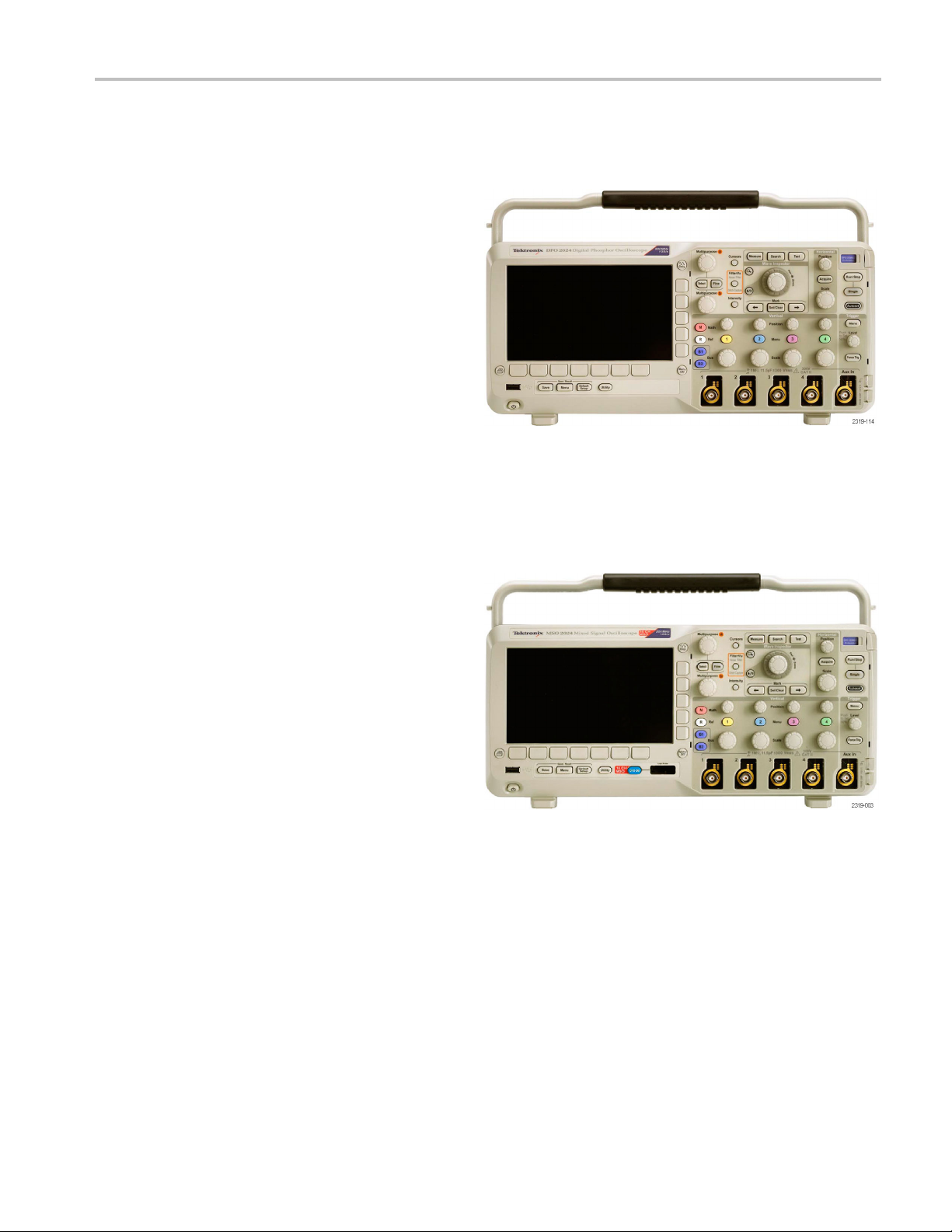
This manual describes the installation and operation of the following oscilloscopes:
DPO2024 DPO2014 DPO2012
MSO2024 MSO2014 MSO2012
Key Features
DPO2000 and MSO2000 series oscilloscopes can help you verify, debug, and characterize electronic designs. Key features
include:
200 MHz and 100 MHz bandwidths
2 channel and 4 channel models
Sample rates up to 1 GS/s on all analog channels
1 M points record length on all channels
5,000 waveforms/second waveform capture rate
I2C, SPI, CAN, LIN, RS-232, RS-422, RS-485, and UART bus triggering and analysis (with the appropriate application
module and model oscilloscope)
Wave Inspector controls for m anaging long record lengths, w ith zoom and pan, play and pause, search and mark
Large 178 mm (7 inch) WQVGA wide screen color display
Small and lightweight, at 140 mm (5.5 inch) deep and 3.6 kg (7 lbs, 14 oz)
FilterVu provides a variable low pass filter to block unwanted noise while still displaying high frequency events
USB flash drive port for quick and easy storage of measurement results
Direct printing to any PictBridge compatible printer
Ethernet port for remote programmability with the optional connectivity module
Video Out port to display the oscilloscope screen on an external monitor with the optional connectivity module
USB 2.0 Device port for direct PC control of the oscilloscope using USBTMC protocol
OpenChoice documentation software for simple transfer of screen shots and waveform data to a PC
National Instrument’s LabVIEW SignalExpress™ Tektronix Edition productivity and analysis software
Remote viewing and control with e*Scope
Remote control with VISA connectivity
TekVPI Versatile Probe Interface supports active, differential, and current probes for automatic scaling and units
MSO2000 series of mixed signal oscilloscopes also offer:
16 digital channels
Parallel bus triggering and analysis
Easy connection to your device-under-test through the convenient design of the P6316 digital probe
x DPO2000 and MSO2000 Series Oscilloscopes User Manual
Page 19

Conventions Used in This Manual
The following icons are used throughout this manual.
Preface
Sequence Step
Front panel power
Connect power
Network
USB
DPO2000 and MSO2000 Series Oscilloscopes User Manual xi
Page 20

Preface
xii DPO2000 and MSO2000 Series Oscilloscopes User Manual
Page 21

Installation
Before Installation
Unpack the oscilloscope and check that you received all items listed as standard accessories. The following pages list
recommended accessories and probes, instrument options, and upgrades. Check the Tektronix Web site (www.tektronix.com)
for the most current information.
Standard Accessories
Accessory Description
DPO2000 and MSO2000 Series
Oscilloscopes User Manual
DPO2000 and MSO2000 Series
Oscilloscopes Documentation Browser
CD
NI LabVIEW SignalExpress Tektronix Edition
andTektronix OpenChoice Desktop PC
Communications CDs
Calibration certificate documenting
traceability to national metrology institute(s),
and ISO9001 quality system registration.
Front panel overlay
English (Option L0)
French (Option L1)
Italian (Option L2)
German (Option L3)
Spanish (Option L4)
Japanese (Option L5)
Portuguese (Option L6)
Simple Chinese (Option L7)
Traditional Chinese (Option L8)
Korean (Option L9)
Russian (Option L10)
Electronic versions of documents, including
the Programmer M anual and the Technical
Reference.
Productivity, analysis, and documentation
software.
French (Option L1)
Italian (Option L2)
German (Option L3)
Spanish (Option L4)
Japanese (Option L5)
Portuguese (Option L6)
Simple Chinese (Option L7)
Traditional Chinese (Option L8)
Korean (Option L9)
Russian (Option L10)
Installation
Tektronix part
number
071-2319‑XX
071-2320‑XX
071-2321‑XX
071-2322‑XX
071-2323‑XX
071-2324‑XX
071-2325‑XX
071-2326‑XX
071-2327‑XX
071-2328‑XX
071-2329‑XX
063-4118‑XX
063-3967‑XX
——
335-2020-00
335-2021-00
335-2022-00
335-2023-00
335-2024-00
335-2025-00
335-2026-00
335-2027-00
335-2028-00
335-2029-00
DPO2000 and MSO2000 Series Oscilloscopes User Manual 1
Page 22

Installation
Standard Accessories (cont.)
Accessory Description
For DPO2000 and MSO2000 series: Probes One, 200 MHz, 1X/10X passive probe per
channel
For MSO2000 series: Digital probe One, 16-channel digital probe
For MSO2000 series: Accessories pouch Pouch that attaches to the handle for carrying
probes and other accessories.
Three year warranty
Power cord
For details, refer to the warranty in the front of
this manual
North America (Opti o n A0)
Universal Euro (Option A1)
United Kingdom (Option A2)
Australia (Option A3)
Switzerland (Option A5)
Japan (Option A6)
China (Option A10)
India (Option A11)
No power cord or AC adapter (Option A99)
Tektronix part
number
P2221
P6316
016-2008-00
——
161-0348-00
161-0343-00
161-0344-00
161-0346-00
161-0347-00
161-0342-00
161-0341-00
161-0349-00
——
2 DPO2000 and MSO2000 Series Oscilloscopes User Manual
Page 23

Optional Accessories
Tektronix part
Accessory Description
DPO2EMBD
The embedded serial triggering and analysis
module enable
informationonI
s triggering on packet level
2
C and SPI serial buses, as
well as bus views, bus decoding, search tools,
and packet de
code tables with timestamp
information
DPO2AUTO
The automoti
ve serial triggering and analysis
module enables triggering on packet level
information on CAN and LIN serial buses, as
well as bus v
iews, bus decoding, search tools,
and packet decode tables with timestamp
information
DPO2COMP
The computer triggering and analysis module
enables triggering on RS-232, RS-422, RS-485
and UART se
rial buses, search tools, bus
views, bus decoding in hex, binary, and ASCII,
and decode tables with timestamp information
DPO2CONN
The connectivity module adds an Ethernet port
for remote programmability and a Video Out
port to di
splay the oscilloscope screen on an
external monitor
NEX-HD2
HEADER
Adapter that routes the channels from a Mictor
connector to 0.1 inch header pins
TPA-BNC TekV PI to TekProbe II BNC Adapter TPA-BNC
TekVPI external power adapter
Supplies external power to a TekVPI probe
Deskew pulse generator Deskew pulse generator and signal source
with TekVPI oscilloscope interface
Power measurement deskew and calibration
fixture
USB-488 Adapter
TEK-
Converts TEK-DPG pulse generator output
a series of test point connections
into
to USB Adapter
GPIB
Rackmount kit Adds rackmount brackets RMD2000
Soft transit case Case for carrying an oscilloscope ACD2000
Hard transit case
PO2000 and MSO2000 Series
D
Oscilloscopes Service manual
Traveling hard case, which requires use of the
ft transit case (ACD2000)
so
ervice information on DPO2000 and
S
MSO2000 series oscilloscopes
number
DPO2EMBD
DPO2AUTO
DPO2COMP
DPO2CONN
NEX-HD2
119‑7465‑XX
TEK-DPG
067-1686-00
USB-488
TEK-
HCTEK4321
071-2331‑XX
Installation
HEADER
DPO2000 and MSO2000 Series Oscilloscopes User Manual 3
Page 24

Installation
Optional Accessories (cont.)
Tektronix part
Accessory Description
DPO2000 and MSO2000 Series
Oscilloscopes Application Module Installation
The DPO2000 and MSO2000 series oscilloscopes work with multiple optional probes. (See page 8, Connecting Probes.)
Check the Tektronix Web site (www.tektronix.com) for the most current information.
Describes how to install application modules in
DPO2000 and MSO2000 series oscilloscopes
number
071-2330‑XX
Related Documentation
Accessory Description Tektronix part number
DPO2000 and MSO2000 Series
Oscilloscopes Programmer Manual
DPO2000 and MSO2000 Series
Oscilloscopes Technical Reference
Manual
Describes commands for remote control
of the oscilloscope; available electronically
on the D ocumentation Browser CD or for
download from www.tektronix.com/manuals
Describes the oscilloscope specifications
and performance verification procedure;
available electronically on the Documentation
Browser CD or for download from
www.tektronix.com/manuals
077-0097‑XX
077-0096‑XX
4 DPO2000 and MSO2000 Series Oscilloscopes User Manual
Page 25
Operating Considerations
DPO2000 and MSO2000 Series Oscilloscopes
Power Supply Input Voltage: 100 V to 240 V ± 10%
Power Supply Input Power Frequency:
50/60 Hz at 100 V to 240 V
400 Hz at 115 V
Power Consumption: 80 W maximum
Weight: 3.6 kg (7 lbs 14 oz), stand-alone oscilloscope
Height, including the feet but not the handle:
175 mm (6.885 inch)
Installation
Width: 377 mm (14.85 inch)
Depth: from the feet to the front of the knobs: 134 mm (5.3 inch)
Depth: fr
Clearan
Input V
300 V
Installation Category II - for measurements performed
on circ
installation
Tempe
Operating: 0 °C to +50 °C
Nonoperating: -20 °C to +60 °C
Humidity:
Operating: High: 40 °C to 50 °C, 10% to 60% RH
Operating: Low: 0 °C to 40 °C, 10% to 90% RH
Non-operating: High: 40 °C to 60 °C, 5% to 60% RH
Non-operating: Low: 0 °C to 40 °C, 5% to 90% RH
om the feet to the front of the front cover: 139 mm (5.47 inch)
ce: 50 mm (2 inch)
oltage (between the signal and reference):
CAT II
RMS
uits directly connected to the low-voltage
rature:
DPO2000 series
MSO2000 series
Altitude:
Operating: 3,000 m (9,842 ft)
Nonoperating Altitude: 12,000 m (39,370 ft)
DPO2000 and MSO2000 Series Oscilloscopes User Manual 5
Page 26

Installation
Random Vibrati
Operating: 0.31 G
Non-operating: 2.46 G
on:
, 5 - 500 Hz, 10 minutes per axis, 3 axes (30 minutes total)
RMS
, 5 - 500 Hz, 10 minutes per axis, 3 axes (30 minutes total)
RMS
Pollution Degree: 2, Indoor use only
CAUTION. To ensure proper cooling, keep the sides and rear of the oscilloscope clear of obstructions.
P2221 Passive Probe
Input Voltage (bet
300 V
RMS
Installation Category II - for measurements performed on circuits directly connected to the low-voltage installation
Temperature:
Operating: 0 °C to +50 °C (+32 °F to +122 °F)
Nonoperating: -5
Pollution Degree: 2, Indoor use only
Humidity: 10% to 95% RH
ween the signal and reference):
CAT II
5 °C to +75 °C ( -67 °F to +167 °F)
MSO2000 Series Oscilloscope with a P6316 Digital Probe
Threshold Accuracy: ±(100 mV + 3% of threshold)
Threshold Range: ±20 V
Maximum nond
Minimum signal swing: 500 mV
Input resistance: 101 kΩ
Input capacitance: 8.0 pF
Temperat
Operating: 0 °C to +50 °C (+32 °F to +122 °F)
Nonoperating: -40 °C to +71 °C (-40 °F to +160 °F)
Altitude:
Operating: 3,000 m (9,843 ft) maximum
Nonoper
Pollution Degree: 2, Indoor use only
estructive input signal to probe: ±40 V
peak-to-peak
ure:
ating: 12,000 m (39,370 ft) maximum
6 DPO2000 and MSO2000 Series Oscilloscopes User Manual
Page 27

Installation
Humidity:
5% to 95% relative humidity
Cleaning
Inspect the oscilloscope and probes as often as operating conditions require. To clean the exterior surface, perform the
following steps:
1. Remove loose dust on the outside of the oscilloscope and probes with a lint-free cloth. Use care to avoid scratching the
clear glass display filter.
2. Use a soft cloth dampened with water to clean the oscilloscope. Use an aqueous solution of 75% isopropyl alcohol
for more efficient cleaning.
CAUTION. To avoid damage to the surface of the oscilloscope or probes, do not use any abrasive or chemical cleaning
agents.
DPO2000 and MSO2000 Series Oscilloscopes User Manual 7
Page 28
Installation
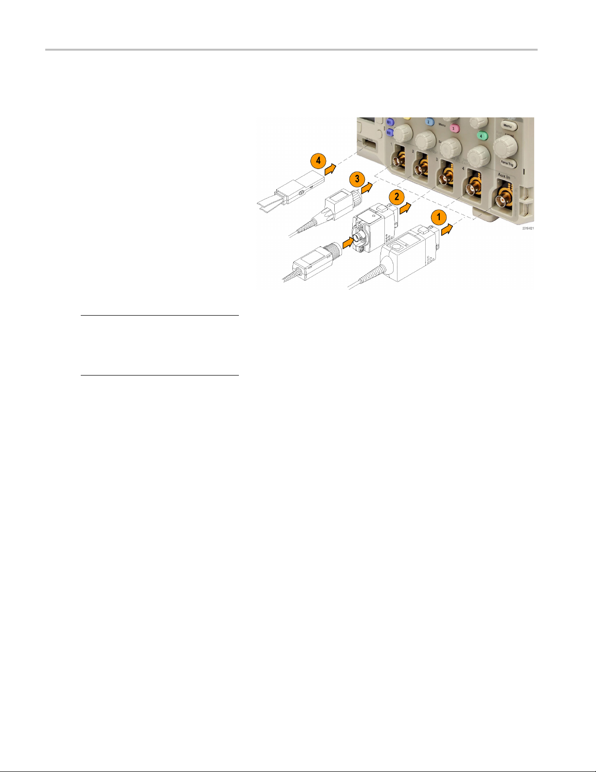
Connecting Probes
The oscilloscope supports probes with the following:
1. Tektronix Versatile Probe Interface
(TekVPI)
These probes support two-way
communication with the oscilloscope
through on-screen menus and remotely
through programmable support. The
remote control is useful in applications
like an ATE (automated test environment)
where you want the system to preset
probe parameters.
2. TPA-BNC Adapter
The TPA-BNC Adapter allows you to
use Tek Probe II probe capabilities,
such as providing probe power, and
passing scaling and unit information to
the oscilloscope.
NOTE. To use a TekVPI probe and a
TPA-BNC adapter, connect a TekVPI
external power adapter (Tektronix part
number 119
Probe Power connector.
‑
7465‑XX) to the side panel
8 DPO2000 and MSO2000 Series Oscilloscopes User Manual
Page 29
3. Plain BNC Interfaces
Some probes use TekProbe capabilities
to pass the wav
to the oscilloscope. Other probes
only pass the signal and there is no
communicati
eform signal and scaling
on.
Installation
4. Digital Prob
only)
The P6316 probe provides 16 channels
of digital (
For more in
www.tektronix.com.
e Interface (MSO2000 series
on or off state) information.
formation on the many probes available for use with DPO2000 and MSO2000 series oscilloscopes, refer to
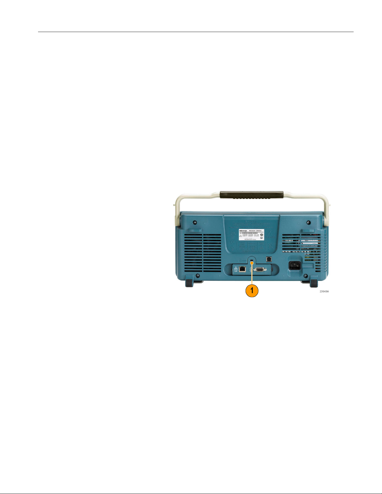
Securing the Oscilloscope
1. Use a standard laptop computer style
security
to your location.
This photo also shows the optional
DPO2CONN
module provides an Ethernet port and a
Video Out port for the oscilloscopes.
lock to secure your oscilloscope
module installed. The
DPO2000 and MSO2000 Series Oscilloscopes User Manual 9
Page 30
Installation
Powering On the Oscilloscope
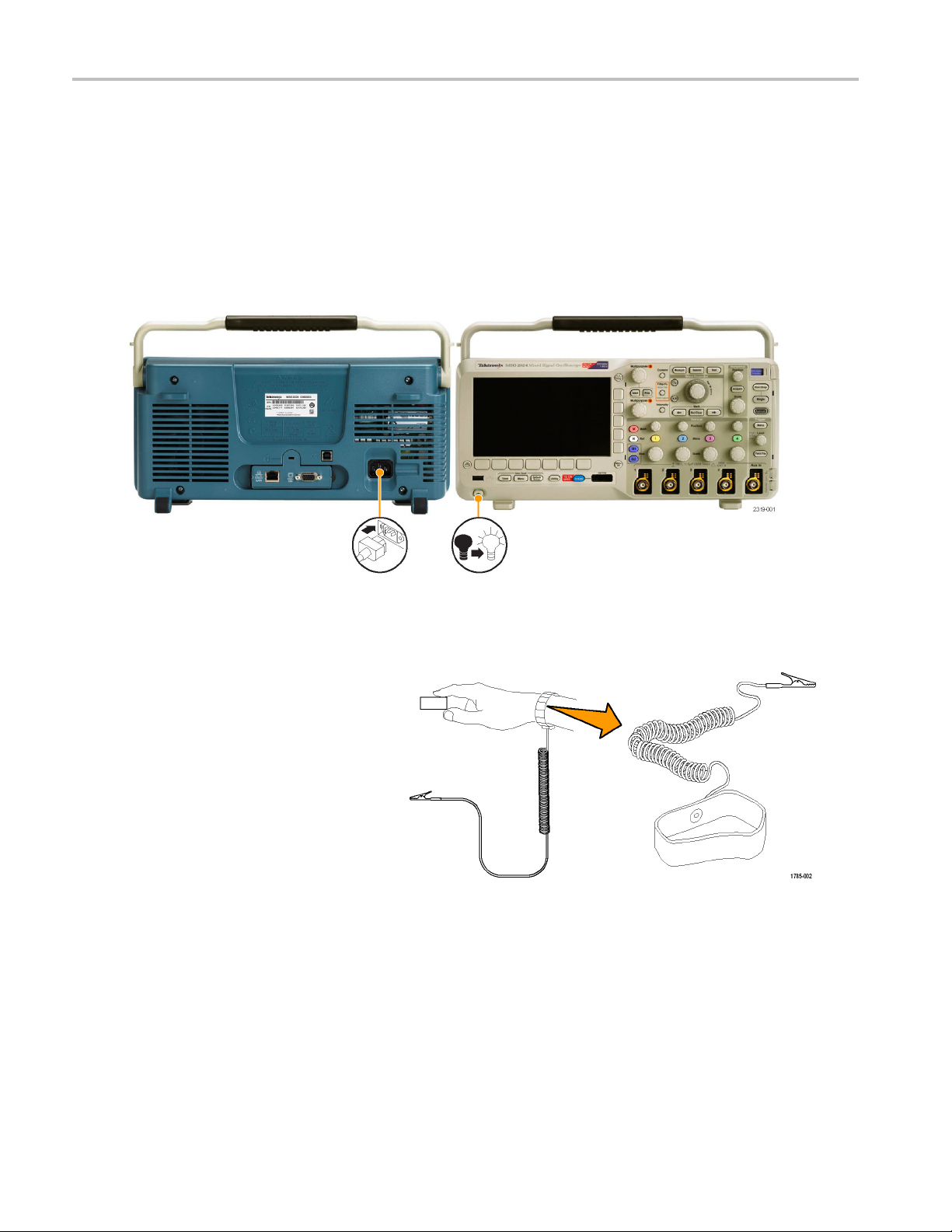
Ground the Oscilloscope and Yourself
Before pushing the power switch, connect the oscilloscope to an electrically neutral reference point, such as earth ground.
Do this by plu
gging the three-pronged power cord into an outlet grounded to earth ground.
Grounding th
same ground as any circuits that you are testing.
To connect the power cord and power on the oscilloscope:
e oscilloscope is necessary for safety and to take accurate measurements. The oscilloscope needs to share the
Quick Tips
Ifyouareworkingwithstaticsensitive
components, ground yourself. Static
electricity that builds up on your body
can damage static-sensitive components.
Wearing a grounding strap safely sends
static charges on your body to earth ground.
10 DPO2000 and MSO2000 Series Oscilloscopes User Manual
Page 31
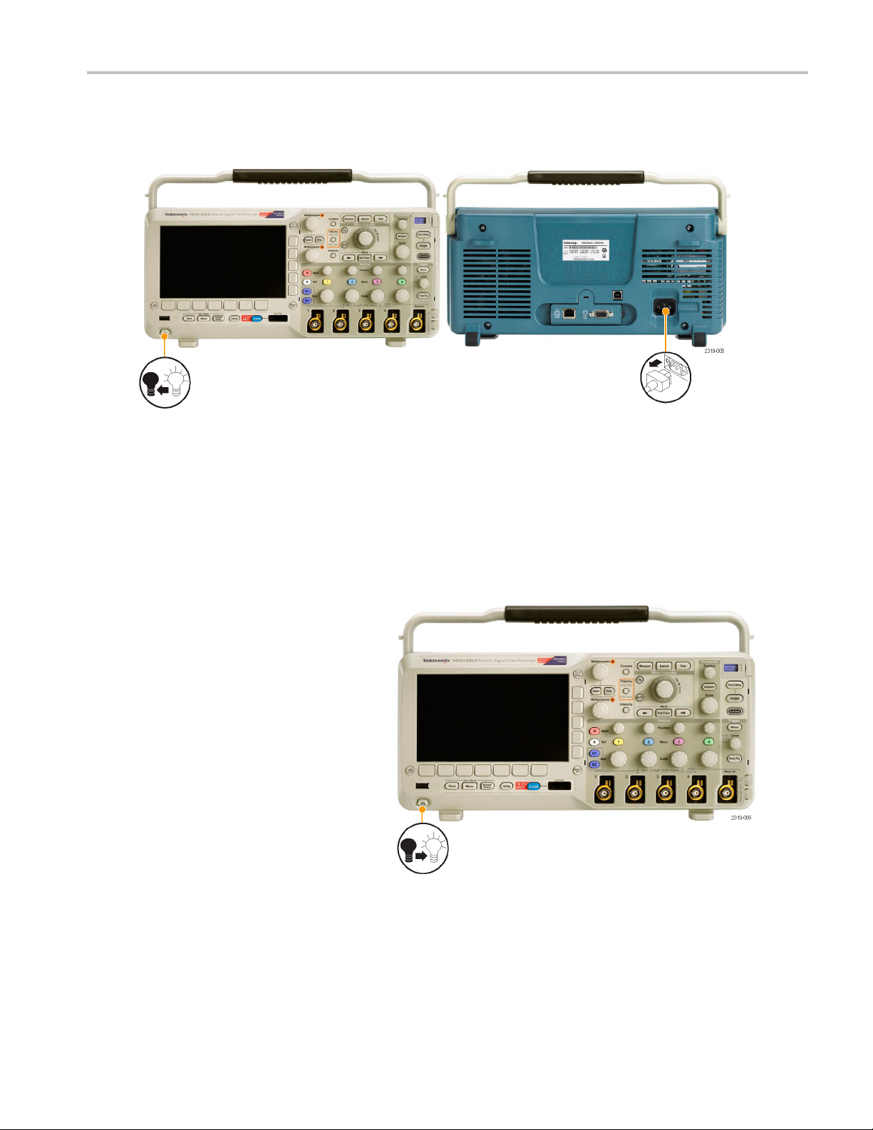
Powering Off the Oscilloscope
To power off the oscilloscope and remove the power cord:
Installation
Functional Check
Perform this quick functional check to verify that your oscilloscope is operating correctly.
1. Connect the oscilloscope power cable
as described in Powering On the
Oscilloscope. (See page 10.)
2. Power on the oscilloscope.
DPO2000 and MSO2000 Series Oscilloscopes User Manual 11
Page 32

Installation
3. Connect the P2221 probe tip and
reference lead to the PROBE COMP
connectors on
4. Push Default Setup .
5. Push Autoset. The screen should now
display a square wave, approximately
5Vat1kHz.
the oscilloscope.
NOTE. For best performance, it is
recommended that you set the Vertical scale
to1V.
If the signal appears but is misshapen,
perform the procedures for compensating
the probe. (See page 12.)
If no signal appears, rerun the procedure.
If this does not remedy the situation,
have the oscilloscope serviced by
qualified service personnel.
Compensating a Passive Voltage Probe
ever you attach a passive voltage probe for the first time to any input channel, compensate the probe to match it to
When
the corresponding oscilloscope input channel.
To properly compensate your passive probe:
1. Follow the steps for the functional
check. (See page 11.)
2. Check the shape of the displayed
waveform to determine if your
probe is properly compensated.
Properly compensated
Under compensated Over compensated
12 DPO2000 and MSO2000 Series Oscilloscopes User Manual
Page 33

3. If necessary, adjust your probe.
Repeat as needed.
Quick Tips
Use the shortest possible ground lead
and signal path to minimize probe-induced
ringing and distortion on the measured
signal.
th a sh ort ground lead
Signal wi
Installation
Signal with a long ground lead
DPO2000 and MSO2000 Series Oscilloscopes User Manual 13
Page 34
Installation
Application Module Free Trial
A 30-day free trial is available for all application modules not installed in your oscilloscope. The trial period begins when you
power on the oscilloscope for the first time.
After 30 days, you must purchase the module if you want to continue using the application. To see the date when your free
trial period expires, push the front panel Utility button, push the lower-bezel Utility Pag e button, use multipurpose knob a to
select Config, and push the lower-bezel About button.
Installing an Application Module
CAUTION. To avoid damage to the oscilloscope or application module, observe ESD (electrostatic discharge) precautions.
(See page 10, Powering On the Oscilloscope.)
Turn off the oscilloscope power while removing or adding an application module.
(See page 11, Powering Off the Oscilloscope.)
Optional application module packages extend the capability of your oscilloscope. You can install one or two application
modules at one time. An application module goes into the slot with a window in the upper right corner of the front panel.
Another slot is directly behind the one that you can see. To use this slot, install the module with the label facing away from you.
For more information on how to install and test application modules, refer to the DPO2000 and MSO2000 Series
Oscilloscopes Application Module Installation manual.
NOTE. If you remove an application module, the features provided by the application module become unavailable. To
restore the features, turn off the oscilloscope power, reinstall the module and turn on the oscilloscope power.
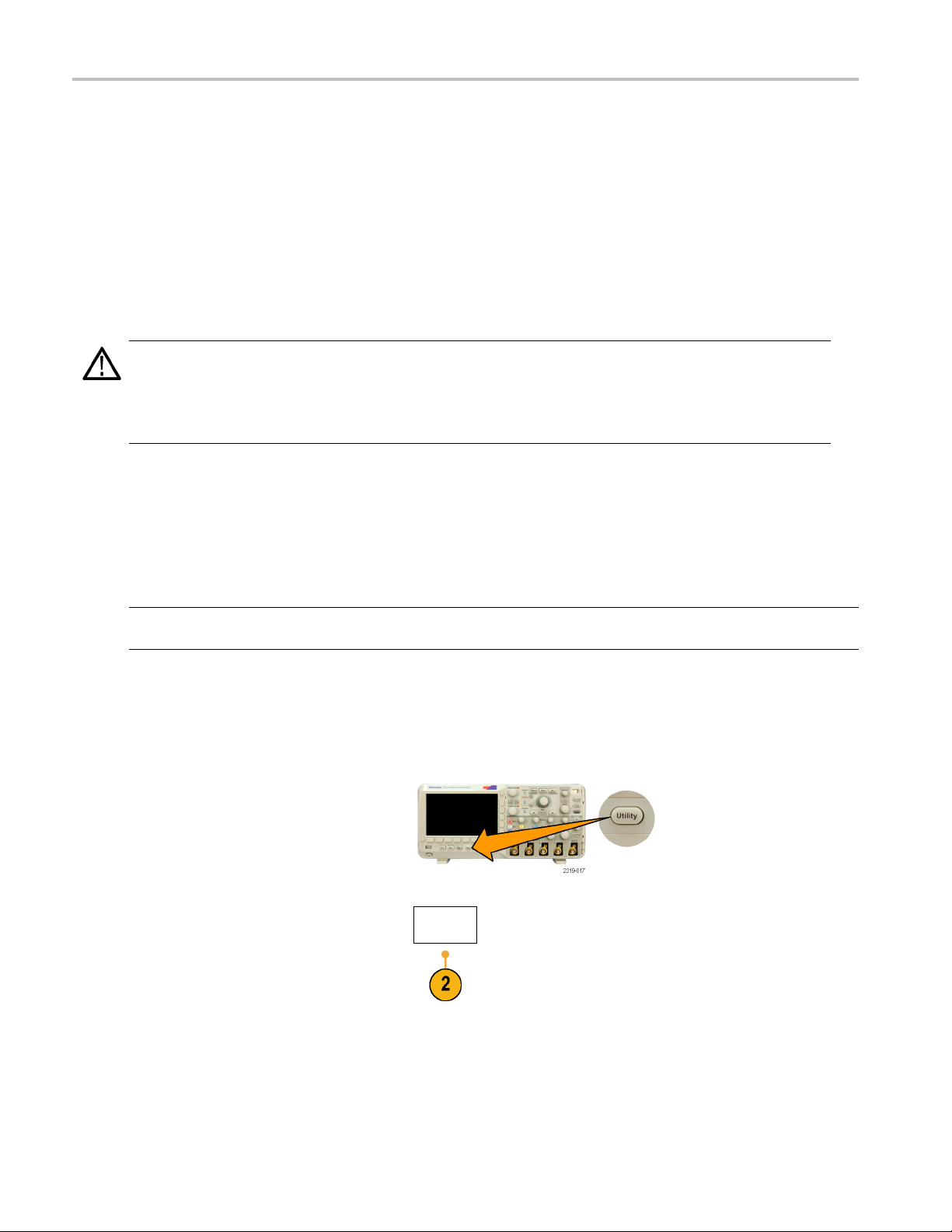
Changing the User Interface Language
To change the language of the o scilloscope user interface, and to change the front-panel button labels through the use
verlay:
of an o
1. Push U
2. Push Utility Page.
tility.
Utility
Pag
e
14 DPO2000 and MSO2000 Series Oscilloscopes User Manual
Page 35

Installation
3. Turn multipurpose knob a and select Config.
4. Push Language
from the resulting
lower-bezel menu.
5. Turn multipu
rpose knob a and select the
desired language. Choose among: English,
French, German, Italian, Spanish, Brazilian
Portuguese
, Russian, Japanese, Korean,
Simplified Chinese, and Traditional Chinese.
6. If you choose to use English, be sure that
the plastic front-panel overlay is removed.
If you choose a language other than English,
place the plastic overlay for the language
that you desire over the front panel to display
labels in that language.
Utility
Page
Config
Language
English
Set Date &
Time
TekSecure
Erase
Memory
About
Changing the Date and Time
the internal clock with the current date and time:
To se t
1. Push
DPO2000 and MSO2000 Series Oscilloscopes User Manual 15
Utility.
Page 36

Installation
2. Push Utility P
age.
3. Turn multipurpose knob a and select Config.
4. Push Set Dat
5. Push the si
e&Time.
de-bezel buttons and use
multipurpose knobs a and b to set the Day,
Month, Year, Hour, and Minute values.
6. Push Display and turn multipurpose knob a
to choose Date & Time, Date Only, Time
Only,or
None.
Utility
Page
System
Config
Set Date &
Time
Display
Time Only
Select
Day
Day
3
Language
English
Set Date &
Time
TekSecure
Erase
Memory
About
7. Push OK Enter Date & Time.
OK Ente
Date &
Time
r
16 DPO2000 and MSO2000 Series Oscilloscopes User Manual
Page 37

Signal Path Compensation
Signal Path Compensation (SPC) corrects for DC inaccuracies caused by temperature variations and/or long-term drift.
You should run the SPC whenever the ambient temperature has changed by more than 10 °C or once a week if you
use vertical settings of 5 mV per division or less. Failure to do so may result in the oscilloscope not meeting warranted
performance levels at those volts per division settings.
To compensate the signal path:
1. Warm up the oscilloscope for at least
20 minutes. Remove all input signals
(probes and cables) from channel inputs.
Input signals with AC components adversely
affect SPC.
Installation
2. Push Utility.
3. Push Utility Page.
4. Turn multipurpose knob a and select
Calibration.
5. Push Signal Path from the lower-bezel
menu.
6. Push OK Com pensate Signal Paths from
the resulting side-bezel menu.
Utility
Page
Utility
Page
Calibration
OK Com-
pensate
Signal
Paths
Signal
Path
Pass
Factory
Pass
DPO2000 and MSO2000 Series Oscilloscopes User Manual 17
Page 38

Installation
The oscillosco
pe displays a message when
the calibration is complete. Push Menu Off
to remove the message.
7. After calibr
ation, v e rify that the status
indicator on the lower-bezel menu displays
Pass.
Utility
Page
Calibration
Signal
Path
Pass
Factory
Pass
If it does not, then recalibrate the
oscilloscope or have the oscilloscope
serviced b
y qualified service personnel.
Service personnel use the factory calibration
s to calibrate the internal voltage
function
references of the oscilloscope using
external sources. Refer to your Tektronix
field offic
e or representative for assistance
with factory calibration.
NOTE. Signal Path Compensation does not include calibration to the probe tip. (See page 12, Compensating a Passive
Voltage Probe.)
Upgrading Firmware
To upgrade the firmware of the oscilloscope:
1. Open up a Web browser and go to
www.tektronix.com/software. Proceed to
the software finder. Download the latest
firmware for your oscilloscope on your PC.
ip the files and copy the firmware.img
Unz
file into the root folder of a USB flash drive.
18 DPO2000 and MSO2000 Series Oscilloscopes User Manual
Page 39
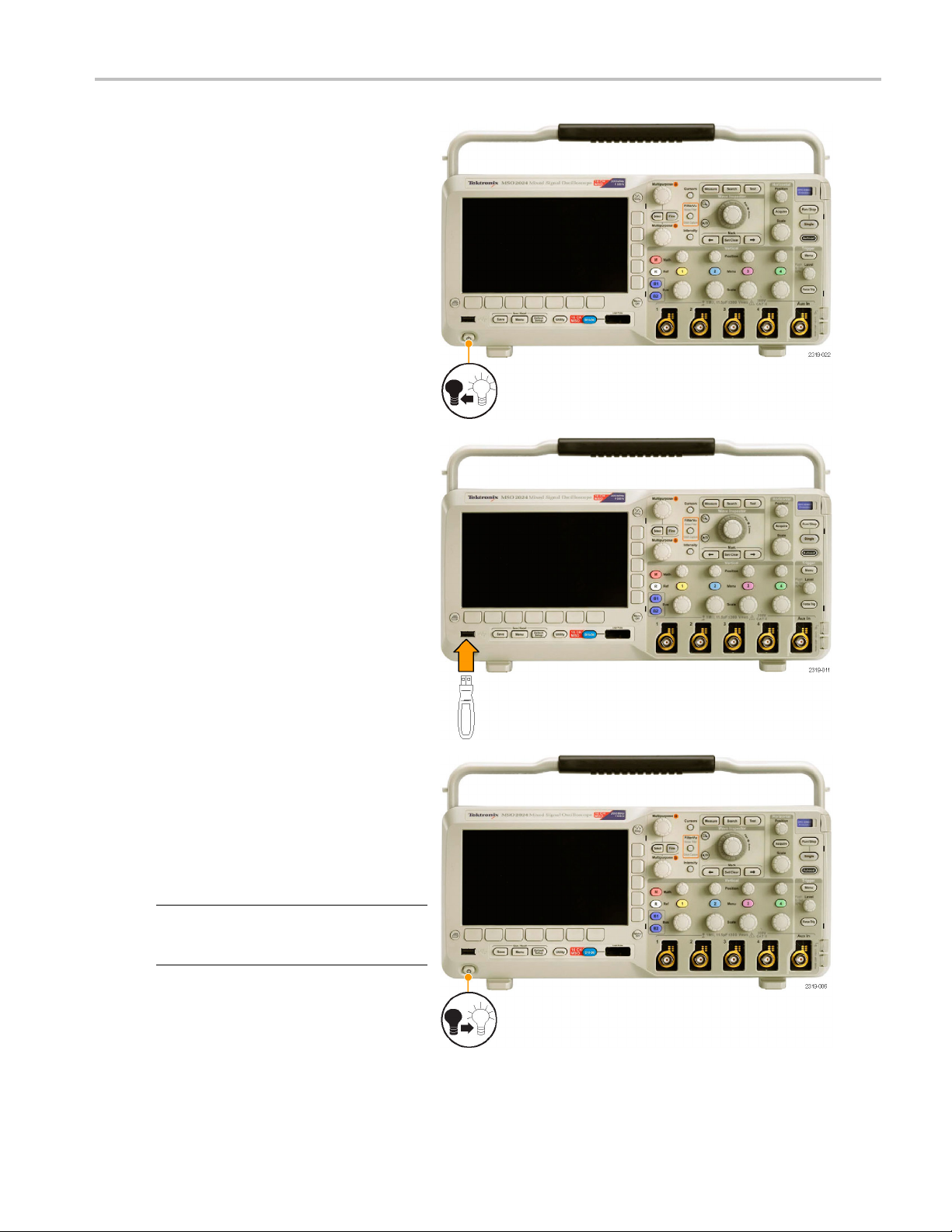
2. Power off your oscilloscope.
3. Insert the USB flash drive into the front-panel
USB port o
n your oscilloscope.
Installation
4. Power on the oscilloscope. The oscilloscope
automatically recognizes and installs the
replacement firmware.
If the oscilloscope does not install the
firmware, rerun the procedure. If the
problem continues, try a different model of
USB flash drive. Finally, if needed, contact
qualified service personnel.
NOTE. Do not power off the oscilloscope or
remove the USB flash drive until the oscilloscope
finishes installing the fi rmware.
DPO2000 and MSO2000 Series Oscilloscopes User Manual 19
Page 40

Installation
5. Power off the oscilloscope and remove the
USB flash drive.
6. Power on the oscilloscope.
7. Push Utility.
ity
8. Push
Utility Page.
Util
Page
20 DPO2000 and MSO2000 Series Oscilloscopes User Manual
Page 41

Installation
9. Turn multipurpose knob a and select Config.
Utility
Page
Config
Language
English
10. Push About. The oscilloscope displays the
firmware versi
11. Confirm that t
on number.
he version number matches
that of the new firmware.
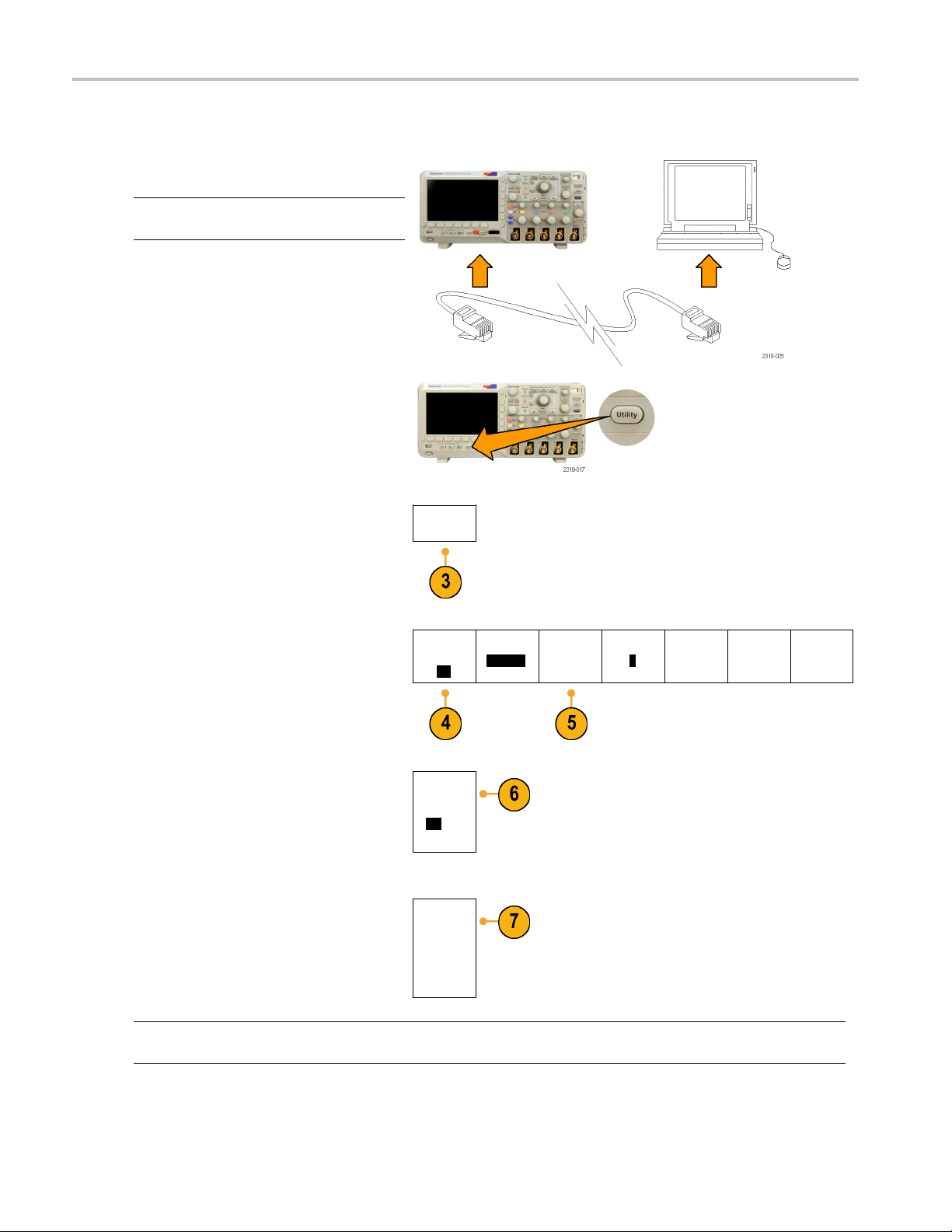
Connecting Your Oscilloscope to a Computer
You may want to document your work for future reference. Instead of saving screen images and waveform data to a USB
flash drive and generating a report later, you may want to get a copy of the image or waveform data directly from a remote
PC for analysis. You may also want to control an oscilloscope at a remote location from your computer. (See page 111,
Saving a Screen Image.) (See page 112, Saving and Recalling Waveform Data.)
Two ways to connect your oscilloscope to a computer are through the V ISA (Virtual Instrument Software Architecture) drivers
and the e*Scope Web-enabled tools. Use VISA to communicate with your oscilloscope from your computer through a
software application. Use e*Scope to communicate with your oscilloscope through a Web browser.
Using VISA
VISA let
runs on your PC, such as Microsoft Excel, National Instruments LabVIEW, or a program of your own creation. You can use a
common communications connection, such as USB or Ethernet, to connect the computer to the oscilloscope.
s you use your MS-Windows computer to acquire data from your oscilloscope for use in an analysis package that
Set Date &
Time
TekSecure
Erase
Memory
About
To set up VISA communications between your oscilloscope and a computer:
1. Load th
e VISA drivers on your computer.
You will find the drivers on the appropriate
CD that comes with your oscilloscope or
Tektronix software finder Web page
at the
(www.tektronix.com).
DPO2000 and MSO2000 Series Oscilloscopes User Manual 21
Page 42

Installation
2. Connect the oscilloscope to your computer
with the appropriate USB or Ethernet cable.
NOTE. You need
a DPO2CONN module to
make the Ethernet connection.
To communicate between the oscilloscope
and a GPIB system, connect the oscilloscope
to the TEK-USB-488 GPIB-to-USB Adapter
with a USB cable. Then connect the adapter
to your GPIB system with a GP IB cable.
Cycle the power on the oscilloscope.
3. Push Utility.
4. Push Utility Page.
5. Turn multipurpose knob a and select I/O.
6. If a USB cable is connected between
the oscilloscope and your computer, the
oscilloscope automatically sets itself up for
you.
Check the USB on the lower-bezel menu to
be sure it is enabled. If it is not enabled, push
USB and make an appropriate selection in
the side-bezel menu.
Utility
Page
Utility
Page
I/O
USB
Computer
Ethernet
Network
Settings
GPIB
1
22 DPO2000 and MSO2000 Series Oscilloscopes User Manual
Page 43

Installation
7. To use Ethernet
, push Ethernet Network
Settings.
8. On the side-be
zel menu, if you are on a
DHCP Ethernet network and using a through
cable, set DHCP to On. If you are using a
cross-over c
able, set it to Off and set a hard
coded TCPIP address.
9. If you are using GPIB, push GPIB. Enter
the GPIB ad
dress on the side-bezel menu,
using multipurpose knob a.
This will
set the GPIB address on an
attached TEK-USB-488 Adapter.
10. Run your
application software on your
computer.
Quick Tips
Change
Instrument
Settings
DHCP/
BOOTP
On|Off
Talk/List
Address
(a) 1
en
The CDs that are shipped with your oscilloscope include a variety of Windows-based software tools designed to ensure
nt connectivity between your oscilloscope and your computer. There are toolbars that enhance connectivity with
efficie
Microsoft Excel and Word. There is also a stand-alone acquisition program called the OpenChoice Desktop.
USB Host port
e front-panel USB 2.0 Host port for USB flash drives and keyboards.
Use th
USB Device port
he rear-panel USB 2.0 Device port for PCs or PictBridge printers.
Use t
ng e*Scope
Usi
e*Scope lets you access any Internet-connected D PO2000 or MSO2000 series oscilloscope from a browser on your
workstation, PC, or laptop computer. No matter where you are, your oscilloscope is as close as the nearest browser.
DPO2000 and MSO2000 Series Oscilloscopes User Manual 23
Page 44
Installation
To set up e*Scope communications between your oscilloscope and a Web browser running on a remote computer:
1. Connect the oscilloscope to your computer
network with the appropriate Ethernet cable.
NOTE. You need a DPO2CONN module to
make the Ethernet connection.
If you are connecting directly to your
computer, y ou need a Crossover Ethernet
Cable. If you are connecting to a network or
a hub, you need a Straight Through Ethernet
Cable.
2. Push Utility.
3. Push Utility Page.
4. Turn multipurpose knob a and select I/O.
5. Push Ethernet Network Settings.
6. On the side-bezel menu, if you are on a
DHCP Ethernet network and using dynamic
addressing, set DHCP to On. If you are
using static addressing, set it to Off.
7. Push Change Instrument Settings.Ifyou
are using DHCP, note the Ethernet address
and instrument name. If you are using Static
addressing, enter the Ethernet address you
will be using.
Utility
Page
Utility
Page
I/O
DHCP/
BOOTP
On|Off
Change
Instrument
Settings
USB
Enabled
Ethernet
Network
Settings
GPIB
1
NOTE. Depending on the type and speed of network to which your oscilloscope is connected, you may not see the
DHCP/BOOTP field update instantaneously after pressing the DHCP/BOOTP button. It may take a few seconds to update.
24 DPO2000 and MSO2000 Series Oscilloscopes User Manual
Page 45

8. Start your browser on your remote computer. In the browser address line, enter the IP address or, if DHCP is set to On
in the oscilloscope, simply enter the instrument name.
You should now
work, rerun the procedure. If it still does not work, contact qualified service personnel.
see the e*Scope screen showing the oscilloscope display on your Web browser. If e*Scope does not
Connecting a USB Keyboard to Your Oscilloscope
You can connect a USB keyboard to the USB Host port on the front panel of the oscilloscope. The oscilloscope will detect the
keyboard, even if it is plugged in while the oscilloscope is powered on. (See page 42, Labeling Channels and Buses.)
Installation
DPO2000 and MSO2000 Series Oscilloscopes User Manual 25
Page 46

Installation
26 DPO2000 and MSO2000 Series Oscilloscopes User Manual
Page 47

Getting Acquain
ted with the Oscilloscope
Getting Acqua
inted with the Oscilloscope
Front-Panel Menus and Controls
The front panel has buttons and controls for the functions that you use most often. Use the menu buttons to access
more specialized functions.
Using the Menu System
To use the menu system:
1. Push a front-panel menu button to
display the menu that you want to use.
2. Push a lower-bezel button to select a
menu item. If a pop-out menu appears,
turn multipurpose knob a to select
the desired choice. If a pop-up menu
appears, press the button again to select
the desired choice.
DPO2000 and MSO2000 Series Oscilloscopes User Manual 27
Page 48

Getting Acquain
ted with the Oscilloscope
3. Push a side-bez
el button to choose a
side-bezel menu item.
If the menu item contains more than
one choice, pu
sh the side-bezel button
repeatedly to cycle through the choices.
If a pop-out menu appears, turn
multipurpos
e knob a to select the desired
choice.
4. Toremoveas
ide-bezel menu, push the
lower-bezel button again or push Menu
Off.
28 DPO2000 and MSO2000 Series Oscilloscopes User Manual
Page 49

5. Certain menu choices require you to set
a numeric value to complete the setup.
Use the upper a
knobs a and b to adjust values.
6. Push Fine to turn off or on the ability to
make smaller adjustments.
nd lower multipurpose
Using the Menu Buttons
Getting Acquain
ted with the Oscilloscope
Use the me
1. Measure. Push to perform automated
2. Search.
3. Test. Push to activate advanced or
4. Acquire. Push to set the acquisition
5. Autoset. Push to perform an automatic
6. Tri
7. Uti
nu buttons to perform many functions in the oscilloscope.
measurements on waveforms or to
ecursors.
configur
Push to search through
an acquisition for user-defined
events/criteria.
application-specific testing features.
mode and adjust the record length.
p of oscilloscope settings.
setu
gger Menu. Push to specify trigger
settings.
lity. P ush to activate the system utility
functions, such as selecting a language
or setting the date/time.
8. Save / Recall Menu. Push to save and
call setups, waveforms, and screen
re
images to internal memory, or a USB
flash drive.
DPO2000 and MSO2000 Series Oscilloscopes User Manual 29
Page 50

Getting Acquain
9. Channel 1, 2, 3,or4Menu. Push
to set vertical parameters for input
waveforms and
the corresponding waveform from the
display.
ted with the Oscilloscope
to display or remove
30 DPO2000 and MSO2000 Series Oscilloscopes User Manual
Page 51

10. B1 or B2. Pushtodefine and
display a serial bus if you have the
appropriate m
The DPO2AUTO module supports CAN
and LIN buses. The DPO2EMBD module
supports I
module supports RS-232, RS-422,
RS-485, and UART buses.
Parallel bus
MSO2000 products.
Also, push the B1 or B2 buttontodisplay
or remove th
the display.
11. R. Push to manage reference waveforms,
including the display or removal of each
referenc
odule application keys.
2
and SPI. The DPO2COMP
C
support is available on
e corresponding bus from
e waveform from the display.
Getting Acquain
ted with the Oscilloscope
12. M.Pushto
including the display or removal of the
math waveform from the display.
Using O
These buttons and knobs control waveforms, cursors, and other data input.
1. Turn the upper multipurpose knob a,
when activated, to move a cursor, to set
a numerical parameter value for a menu
item, or to select from a pop-out list of
choices. Push the Fine button to toggle
between coarse and fine adjustment.
Screen icons tell you when a or b are
active.
2. Cursors. Push once to activate the
two vertical cursors. Push again to turn
on the two vertical and two horizontal
cursors. Push again to turn off all
cursors.
When the cursors are on, you can turn
the multipurpose knobs to control their
position.
manage the math waveform,
ther Controls
DPO2000 and MSO2000 Series Oscilloscopes User Manual 31
Page 52

Getting Acquain
3. Select. Push to activate special
functions.
For example, w
cursors (and no horizontal ones are
visible), you can push this button to link
or unlink the
vertical and two horizontal cursors are
both visible, you can push this button to
make either t
horizontal cursors active.
4. FilterVu.Pushtofilter unwanted noise
from your signal and still capture glitches.
5. Fine. Push to toggle between making
coarse and fine adjustments with the
vertical
trigger level knob, and many operations
of multipurpose knobs a and b.
6. Intensity. Push to enable multipurpose
knob a to control waveform display
intensi
intensity.
ted with the Oscilloscope
hen using the two vertical
cursors. When the two
he vertical cursors or the
and horizontal position knobs, the
ty and knob b to control graticule
7. Turn th
8. Zoom b
9. Pan (outer knob). Turn to scroll the zoom
10. Zoom (inner knob). Turn to control the
11. Play-pause button. Push to start or stop
e lower multipurpose knob b,
when activated, to move a cursor or set
a numerical parameter value for a menu
ush Fine to make adjustments
item. P
more slowly.
utton. Push to activate zoom
mode.
window through the acquired waveform.
m factor. Turning it clockwise zooms
zoo
in further. Turning it counterclockwise
zooms out.
the automatic panning of a waveform.
ntrol the speed and direction with the
Co
pan knob.
32 DPO2000 and MSO2000 Series Oscilloscopes User Manual
Page 53

Getting Acquain
ted with the Oscilloscope
12. ← Prev. Push to j
waveform mark.
13. Set/Clear Mark. Push to establish or
delete a waveform mark.
14. → Next. Push to jump to the next
waveform mark.
15. Horizontal Position. Turn to adjust
the trigger point location relative to the
acquired wa
smaller adjustments.
16. Horizontal Scale. Turn to adjust the
horizontal scale (time/division).
17. Run/Stop. Push to start or stop
acquisitions.
18. Single. Push to make a single
acquisition.
ump to the previous
veforms. Push Fine to make
19. Autoset. Push to automatically set the
vertical, horizontal, and trigger controls
for a usable, stable display.
20. Trigger Level. Turn to adjust the trigger
level.
Push Level to Set 50%. Push the
Trigger level knob to set the trigger level
to the midpoint of the waveform.
21. Force Trig. Push to force an immediate
trigger event.
22. Vertical Position. Turn to adjust the
vertical position of the corresponding
eform. Push Fine to make smaller
wav
adjustments.
2, 3, 4 Menu. Push to display or
23.1,
remove the corresponding waveform
from the display and access the vertical
nu.
me
DPO2000 and MSO2000 Series Oscilloscopes User Manual 33
Page 54

Getting Acquain
24. Vertical Scale. Turn to adjust the
vertical scale factor of the corresponding
waveform (vol
25. Print. Push to print to a PictBridge
printer.
ted with the Oscilloscope
ts/division).
26. P ower switc
the oscilloscope.
27. USB 2.0 Host port. Insert a USB
peripheral to the oscilloscope, such as a
keyboard o
28. S ave. Pus
save operation. The save operation uses
the current save parameters, as defined
in the Sav
29. Default Setup. Push to perform an
immediate restore of the oscilloscope to
the default settings.
30. D15 - D0. Push to display or remove the
digital channels from the display, and to
access the digital channel setup menu
(MSO2000 series only).
h. Push to power on or off
raflash drive.
h to perform an immediate
e / Recall menu.
31. Menu Off. Push to clear a displayed
menu from the screen.
34 DPO2000 and MSO2000 Series Oscilloscopes User Manual
Page 55

32. Waveform Only. Push to remove menu
and readout information from the screen
so the oscillo
waveform or bus. Push a second time
to recall the previous menu and readout
information
scope only displays the
.
Identifying Items in the Display
The items shown to the right may appear in
the display. Not all of these items are visible
at any give
outside the graticule area when menus are
turned off.
n time. Some readouts move
Getting Acquain
ted with the Oscilloscope
1. The acquisition readout shows when an
acquisition is running, stopped, or when
acquisition preview is in effect. Icons are:
Run: Acquisitions enabled
Stop: Acquisitions not enabled
Roll: In Roll mode (40 ms per division
or slower)
PreVu: In this state, the oscilloscope
is stopped or between triggers.
You can change the horizontal
or vertical position or scale to
see approximately what the next
acquisition will look like.
DPO2000 and MSO2000 Series Oscilloscopes User Manual 35
Page 56

Getting Acquain
ted with the Oscilloscope
2. The trigger sta
status. Status conditions are:
Trig’d: Triggered
Auto: Acquiring untriggered data
PrTrig: Acquiring pretrigger data
Trig?: Waiting for trigger
3. The trigger
the trigger occurred in the acquisition.
4. The expansion point icon (an orange
e) shows the point that the
triangl
horizontal scale expands and
compresses around.
tus readout shows trigger
position icon shows where
5. The waveform record view shows the
r location relative to the waveform
trigge
record. The line color corresponds to the
selected waveform color.
6. The FilterVu indicator shows if the
ble low pass filter is active.
varia
7. The cursor readout shows time,
itude, and delta (Δ) values for each
ampl
cursor.
For FFT measurements, it shows
uency and magnitude.
freq
For serial buses, the readout shows the
decoded values.
36 DPO2000 and MSO2000 Series Oscilloscopes User Manual
Page 57

Getting Acquain
ted with the Oscilloscope
8. The trigger lev
level on the waveform. The icon color
corresponds to the trigger source color.
9. The trigger readout shows the trigger
source, slope, level, and frequency for
an Edge trigger. The trigger readouts
for other trigger types show other
parameters.
10. The horizontal position/scale readout
shows on the top line the horizontal scale
(adjust with the Horizontal Scale knob).
With Delay Mode on, the bottom line
shows the time from the T symbol to the
expansion point icon (adjust with the
Horizontal Position knob).
Use horizontal position to insert added
delay between when the trigger occurs
and when you actually capture the data.
Insert a negative time to capture more
pretrigger information.
With Delay Mode off, the bottom line
shows the time location of the trigger
within the acquisition, as a percentage.
el icon shows the trigger
11. Measurement readouts show the
selected measurements. You can select
up to four measurements to display at
one time.
A
symbol appears instead of the
expected numerical measurement if a
vertical clipping condition exists. Part
of the waveform is above or below the
display. To obtain a proper numerical
measurement, turn the vertical scale
and position knobs to make all of the
waveform appear in the display.
12. The auxiliary waveform readouts show
the vertical and horizontal scale factors
of the math and reference waveforms.
DPO2000 and MSO2000 Series Oscilloscopes User Manual 37
Page 58
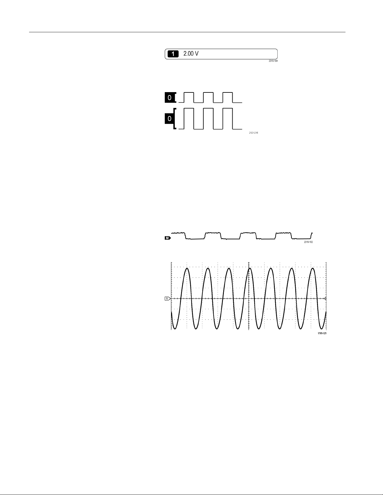
Getting Acquain
ted with the Oscilloscope
13. The c hannel rea
scale factor (per division), coupling,
invert, and bandwidth status. Adjust with
the Vertical S
1, 2, 3,or4 menus.
14. For digital channels (MSO2000 series
only), the baseline indicators label the
channel, and
levels. The colors follow the color code
used on resistors. The D0 indicator is
black, the D
D2 indicator is red, and so on.
The bus display shows decoded packet
level info
parallel buses (MSO2000 series only).
The bus indicator shows the bus number
and bus typ
Not shown in this illustration, the Timing
Resoluti
resolution of the digital channels. To see
the readout, push the D15-D0 front panel
button.
dout shows the channel
cale knob and the channel
point to the high and low
1 indicator is brown, the
rmation for serial buses or for
e.
on readout shows the timing
15. For math
baseline indicator shows the zero-volt
level of a waveform.
16. For analog channels, the waveform
basel
level of a waveform (ignoring the effect
of offset). The icon colors correspond to
the wa
channels, the waveform
ine indicator shows the zero-volt
veform colors.
38 DPO2000 and MSO2000 Series Oscilloscopes User Manual
Page 59

Front-Panel Connectors
Getting Acquain
ted with the Oscilloscope
1. Digital Probe
(MSO2000 series only).
2. Channel 1, 2,(3, 4). Channel inputs with
TekVPI Versatile Probe Interface.
3. Aux In. Trigger level range is adjustable
from +12.5 V t
4. PROBE COMP.
source to compensate probes.
Output voltage: 0 V to 5 V
Frequency
5. Ground.
6. Applicati
Connector
o –12.5 V.
Square wave signal
:1kHz
on Module Slots.
Side-Panel Connector
1. TekVPI external power supply connector.
Use the connector for the TekVPI
l power supply (Tektronix part
externa
number 119‑7465‑XX) when additional
power is needed for TekVPI probes.
DPO2000 and MSO2000 Series Oscilloscopes User Manual 39
Page 60

Getting Acquain
ted with the Oscilloscope
Rear-Panel Connectors
1. LAN.UsetheLA
connector) to connect the oscilloscope
to a 10/100 Base-T local area network.
The port is ava
connectivity module (DPO2CONN).
2. Lock. Use to secure the oscilloscope
and optional connectivitiy module.
3. Video Out. Use the Video Out port
(DB-15 fema
oscilloscope display on an external
monitor or projector. The port is available
on the opti
(DPO2CONN).
4. USB 2.0 Device port.UsetheUSB
2.0 Full Speed Device port to connect
aPictBri
direct PC control of the oscilloscope
using USBTMC protocol.
5. Power input. Attach to an AC power line
with int
Operating Considerations.)
dge compatible printer, or for
egral safety ground. (See page 5,
N (Ethernet) port (RJ-45
ilable on the optional
le connector) to show the
onal connectivity module
40 DPO2000 and MSO2000 Series Oscilloscopes User Manual
Page 61

Acquire the Sign
al
Acquire the Si
This section describes concepts of and procedures for setti ng up the oscilloscope to acquire the signal as you want it to.
gnal
SettingUpAnalogChannels
Use front-panel buttons and knobs to set up your oscilloscope to acquire signals using the analog channels.
1. Connect a P2221 probe or a TekVPI
probe to the
2. Push Default Setup.
NOTE. If you are using a probe that does not
supply p
(probe factor) o n the oscilloscope vertical
menu to match the probe. The default
tion for the oscilloscope is 10X and is
attenua
set in the Probe Setup lower-bezel menu of
any analog channel.
input signal source.
robe encoding, set the attenuation
3. Select the input channel by pushing the
front-panel buttons.
4. Push Autoset.
DPO2000 and MSO2000 Series Oscilloscopes User Manual 41
Page 62

Acquire the Sign
al
5. Push the desire
adjust the vertical position and scale.
6. Adjust the horizontal position and scale.
The horizontal position determines the
number of pretrigger and posttrigger
samples.
The horizontal scale determines the size
of the acquisition window relative to the
waveform. You can scale the window to
contain a waveform edge, a cycle, several
cycles, or thousands of cycles.
d channel button. Then
Quick Tip
Use the zoom feature to see multiple cycles of your signal in the upper part, and a single cycle in the lower part of the
display. (See page 103, Using Wave Inspector to Manage Long Record Length Waveforms.)
Labeling Channels and Buses
You can
waveform baseline indicator in the left side of the screen. The label can have up to 32 characters.
To label a channel, push a channel input button for an analog channel to label a channel.
add a label to the channels and buses shown on the display for easy identification. The label is placed on the
1. Push a front panel button for an input
el or a bus.
chann
42 DPO2000 and MSO2000 Series Oscilloscopes User Manual
Page 63

Acquire the Sign
al
2. Push a lower-b
ezel button to create a label,
such as for channel 1 or B1.
3. Turn multipu
rpose knob b to scroll through
the list to find a suitable label. You can edit
the label after you insert it if necessary.
4. Push Insert Preset Label to add the label.
If you are using a USB keyboard, use the
arrow keys to position the insertion point and
edit the inserted label, or type in a new label.
(See page 25, Connecting a USB Keyboard
to Your Oscilloscope.)
Label
Insert
Preset
Label
5. If you do not have a USB keyboard
connected, push the side- and lower-bezel
eys to position the insertion point.
arrow k
6. Turn multipurpose knob a to scroll through
the list of letters, numbers, and other
characters to find the character in the name
that you want to enter.
ABCDEFGHIJKLMNOPQRSTUVWXYZ
cdefghijklmnopqrstuvwxyz
ab
0123456789_=+-!@#$%^&*()[]{}<>/~’”\|:,.?
DPO2000 and MSO2000 Series Oscilloscopes User Manual 43
Page 64

Acquire the Sign
7. Push Select or Enter Character to let the
al
oscilloscope know that you have picked the
proper charac
ter to use.
8. Continue scrolling and pushing Select until
9. Push Display Labels and select On to see
Using th
To return the oscilloscope to its default settings:
1. Push Default Setup.
You can use the lower-bezel buttons to edit
the label as n
you have ent
eeded.
ered all the desired characters.
For another label, push the side- and
lower-bezel arrow keys to reposition the
insertion
the label
point.
.
eDefaultSetup
Enter
Character
Display
Labels
On|Off
Back
Space
Delete
Clear
2. If you change your mind, push Undo
Default Setup to undo the last default
Undo
Default
Setup
setup.
44 DPO2000 and MSO2000 Series Oscilloscopes User Manual
Page 65

Using Autoset
Autoset adjusts the oscilloscope (acquisition, horizontal, trigger, and vertical controls) such that it displays four or five
waveform cycles for analog channels with the trigger near the middle level, and ten cycles for digital channels.
Autoset works with both the analog and digital channels.
1. Connect the analog probe, and then select
the input channel. (See page 41, Setting
Up Analog Channels.)
Connect the digital probe and select the
input chann
Digital C hannels (MSO2000 Series Only).)
2. Push Autoset to execute an A utoset.
el. (See page 60, Setting Up
Acquire the Sign
al
3. If desired, push Undo Autoset to undo
Autoset.
the last
You can also disable the Autoset function if you want to set up a waveform manually. To disable or enable the Autoset function:
1. Push and hold Autoset.
2. Push a
3. Release Menu Off, and then release
nd hold Menu Off.
set.
Auto
Undo
Autoset
DPO2000 and MSO2000 Series Oscilloscopes User Manual 45
Page 66

Acquire the Sign
al
4. Select the desired side-bezel setting.
Autoset
Enabled
Autoset
Disabled
Quick Tips
To position the waveform appropriately, Autoset may change the vertical position. Autoset always sets vertical offset
to0V.
If you use Autoset when no channels are displayed, the oscilloscope turns on channel one (1) and scales it.
If you use Autoset and the oscilloscope detects a video signal, the oscilloscope automatically sets the trigger type to
video and makes other adjustments to display a stable video signal.
To manually set the oscilloscope to view a video signal in an IRE graticule:
1. Set the Trigger Type to Video.
2. Set the Vertical Scale to 143mV/div.
3. Select the proper input channel Attenuation for the probe or cable being used to feed the video signal to the
oscilloscope.
4. If necessary, connect a 75 ohm pass-through terminator to the oscilloscope input. For example, you need to add a
terminator when you use a 75-ohm cable between the video signal and the oscilloscope.
Acquisition Concepts
Before a signal can be displayed, it must pass through the input channel where it is scaled and digitized. Each channel
has a de
extracts waveform records.
Sampling Process
Acqui
analog signal, converting it into digital
data, and assembling it into a waveform
reco
memory.
dicated input amplifier and digitizer. Each channel produces a stream of digital data from which the oscilloscope
sition is the process of sampling an
rd, which is then stored in acquisition
Input signal
Sampled points
Digital values
46 DPO2000 and MSO2000 Series Oscilloscopes User Manual
Page 67

Real-Time Sampling
Acquire the Sign
al
DPO2000 and MS
oscilloscopes use real-time sampling.
In real-time sampling, the oscilloscope
digitizes all
single trigger event.
Waveform R
The oscilloscope builds the waveform record through the use of the following parameters:
Sample interval: The time between
recorded sample points. Adjust this by
turning the Horizontal Scale knob or
changing the record length with the bezel
buttons.
Record length: The number of samples
required to fill a waveform record. Set
this by pushing the Acquire button and
using the resulting lower- and side-bezel
menus.
O2000 series
of the points it acquires using a
ecord
Record points
Sampling rate
Trigger point: The zero time reference in a waveform record. It is shown on the screen by an orange T.
Horizontal position: When the Delay mode is on, this is the time from the trigger point to the expansion point. Adjust this
ning the Horizontal Position knob.
by tur
When the Delay mode is off, the expansion point is fixed to the trigger point. (Push the Acquire front panel button
to set the Delay mode.)
positive time to acquire the record after the trigger point. Use a negative time to acquire it before the trigger point.
Use a
Expansion point: The point that the horizontal scale expands and contracts around. It is shown by an orange triangle.
DPO2000 and MSO2000 Series Oscilloscopes User Manual 47
Page 68

Acquire the Sign
al
How the Analog Acquisition M odes Work
FilterVu Noise Filter F oreground mode
retains the first sampled point from each
acquisition i
Sample in other oscilloscopes. This is the
default mode.
FilterVu Glitch Capture Background mode
uses the high
samples contained in two consecutive
acquisition intervals. At fast time per division
settings, t
mode is unavailable. This mode is also
called Peak Detect in other oscilloscopes.
Average mode calculates the average value
for each record point over a user-specified
number of a
Sample mode for each individual acquisition.
Use Average mode to reduce random noise.
nterval. This mode is also called
est and lowest of all the
he Glitch Capture Background
cquisitions. Average uses
Changin
Use this procedure to change the acquisition mode.
1. Push Acquire.
2. Push Average.
3. Set the Average acquisition mode from the
g the Acquisition Mode, Record Length, and Delay Time
age
Record
Lengt
100k
Delay
h
On |
Off
Set Horiz.
Position to
10%
Waveform
Display
side-bezel menu. You can chose how many
ples on which to average: 2, 4, 8, 16,
sam
32, 64, 128, 256, or 512.
Average
Off
Aver
Average
On |Off
XY Display
Off
Acquisition
ls
Detai
48 DPO2000 and MSO2000 Series Oscilloscopes User Manual
Page 69

Acquire the Sign
al
4. Turn multipurp
ose knob a to set the number
of waveforms to average over.
5. Push Record Length.
Choose 100 k or 1.00 M points. The
selections depend on the horizontal time per
division setting. 125 k and 1.25 M records
lengths are available at slower time per
division settings.
DPO2000 and MSO2000 Series Oscilloscopes User Manual 49
Page 70

Acquire the Sign
al
6. Push the lower-
On when you want to delay the acquisition
relative to the trigger event.
With Delay set to On, turn the Horizontal Position knob counterclockwise to increase the delay. The trigger point will move
to the left and ultimately outside of the acquired waveform. Then you can adjust the Horizontal Scale knob to acquire more
detail around the area of interest at the center of the screen.
When this delay is on, the trigger point separates from the horizontal expansion point. T he horizontal expansion point
stays at the center of the screen. The trigger point can move off the screen. When this happens, the trigger marker turns
to point in the direction of the trigger point.
Use the delay feature when you want to acquire waveform detail that is separated from the trigger event by a significant
interval of time. For example, you can trigger on a sync pulse that occurs once every 10 ms and then look at high-speed
signal characteristics that occur 6 ms after the sync pulse.
When the delay feature is s et to Off, the expansion point is tied to the trigger point so that scale changes are centered
around the trigger point.
Using Roll Mode
bezel Delay buttontoselect
Roll mode gives a display similar to a strip chart recorder for low-frequency signals. Roll mode lets you see acquired data
points w
Roll mo
ithout waiting for the acquisition of a complete waveform record.
de is enabled when the trigger mode is auto and the horizontal scale is set to 40 ms/division or slower.
Quick Tips
Roll mode is disabled when you switch to Average acquisition mode, use digital channels, use math waveforms, turn on
a bus, switch to Normal trigger, or set the horizontal scale to 20 ms per division or faster.
Zoom is disabled when you use Roll mode.
Push Run/Stop to halt Roll mode.
50 DPO2000 and MSO2000 Series Oscilloscopes User Manual
Page 71

SettingUpaSerialorParallelBus
Your oscilloscope can decode and trigger on:
I2C and SPI serial buses if the DPO2EMBD application module is installed
CAN and LIN serial buses if the DPO2AUTO application module is installed
RS-232, RS-422, RS-485, and UART serial buses if the DPO2COMP application module is installed
Parallel buses if you are using an MSO2000 series oscilloscope
(See page 14, Application Module Free Trial.)
Using Buses in Two Steps
To quickly use serial bus triggering:
Acquire the Sign
al
1. Push B1 or
the bus to trigger on.
You can separately use B1 and B2 to
view two d
2. Push Trigger Menu and enter trigger
parameters. (See page 68, Choosing a
Trigger Type.)
You can display bus information without
triggering on the bus signal.
B2 and enter parameters of
ifferent buses.
SettingUpBusParameters
NOTE.
To trigger on serial or parallel bus conditions, refer to Triggering on Buses. (See page 70, Triggering on Buses.)
For all serial bus sources, use any combination of channels 1 through 4, and D15 through D0.
DPO2000 and MSO2000 Series Oscilloscopes User Manual 51
Page 72

Acquire the Sign
To set up bus parameters:
1. Push B1 or B2 to bring up the lower-bezel
al
bus menu.
2. Push Bus. Turn multipurpose knob a to scroll
through the list of bus types and select the
desired bus: Parallel (MSO2000 series only),
2
I
C, SPI, CAN, RS-232, or LIN.
The actual menu items shown will depend on
your model oscilloscope and the application
modules installed.
3. Push Define Inputs. The choices depend
on the selected bus.
Use the side-bezel buttons to define
parameters for the inputs, such as specific
signals to an analog or digital channel.
If you select Parallel, push the side-bezel
button to enable or disable Clocked Data.
Push the side-bezel button to select the
Clock Edge on which to clock data: rising
edge, falling edge, or both edges.
Turn multipurpose knob a to select the
Number of Data Bits in the parallel bus.
Turn multipurpose knob a to select the
desired bit to define.
Turn multipurpose knob b to select the
desired analog or digital channel as the
source for the bit.
B1
Parallel
Define
Inputs
Clocked
Data
Yes |
No
Clock
Edge
Number of
Data Bits
(a) 16
Define Bits
t15
(a) Bi
(b) D15
Define
Inputs
Thresholds B1 Label
Parallel
Bus
Display
Event
Tab l e
52 DPO2000 and MSO2000 Series Oscilloscopes User Manual
Page 73

Acquire the Sign
al
4. Push Threshol
You can set the
ds.
threshold for all channels in
the parallel or serial bus from a list of preset
values. The values are based on common
types of inte
grated circuits. The preset
values are:
1.4 V for TTL
2.5 V for 5.0
VCMOS
1.65 V for 3.3 V CMOS
1.25 V for 2.5 V CMOS
-1.3 V for E
CL
3.7 V for PECL
0V
Alternate
ly, you can set the threshold to a
specific value for the signals that makes
up the parallel or serial bus. To do so,
push the S
elect side-bezel button and turn
multipurpose knob a to select a Bit or a
Channel number (Signal name).
Bus
Parallel
Define
Inputs
Thresholds B1 Label
Parallel
Bus
Display
Event
Table
Then, turn multipurpose knob b to define the
voltage level above which the oscilloscope
treats the signal as high and below which
as low.
5. Push B1 Label to edit the label for the
bus. (See page 42, Labeling Channels and
s.)
Buse
Bus
Parallel
Define
Input
holds
Thres
s
B1 Lab
Parallel
el
Bus
Display
Event
Table
DPO2000 and MSO2000 Series Oscilloscopes User Manual 53
Page 74
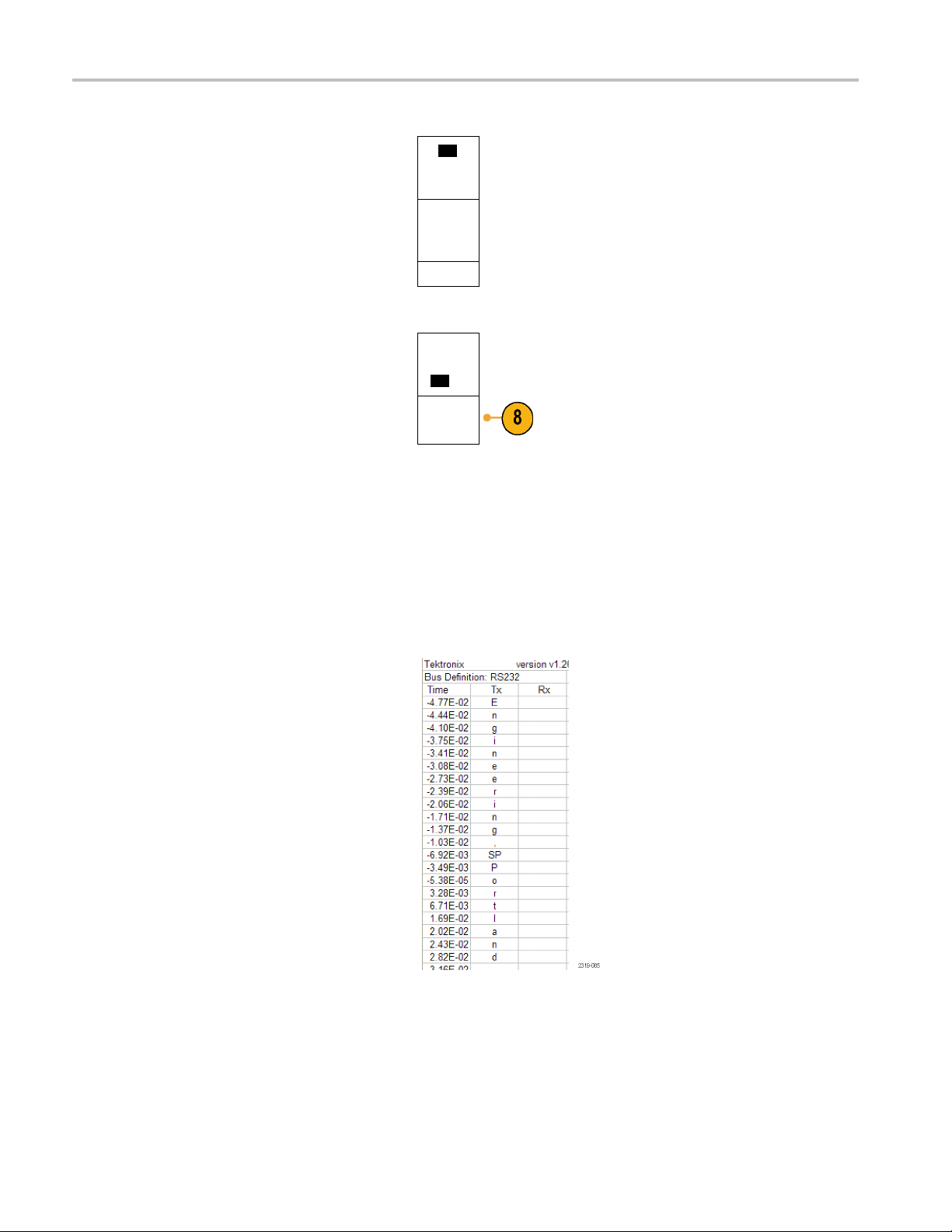
Acquire the Sign
al
6. Push Bus Displ
ay and use the side-bezel
menu to define how to display the parallel or
serial bus.
Push the desir
ed side-bezel menu choice to
display the bus data in hex, binary, or ASCII
(RS-232 only) format.
7. Push Event Table and select On to display
alistofI
with times
For a cloc
2
C, SPI, CAN, or LIN bus packets
tamps.
ked parallel bus, the table lists the
value of the bus at each clock edge. For
an unclocked parallel bus, the table lists the
value of t
he bus whenever any one of its bits
changes.
For an RS-232 bus, the table lists decoded
r packets.
bytes, o
Hex
Binary
ASCII
Event
Tabl e
On |Off
Save
Event
Tabl e
8. Push Sav
e Event Table to save the event
table data in a .csv (spreadsheet) formatted
file on the currently selected storage device.
This example of an Event Table is from an
RS-232 bus.
2 event tables display one line for each
RS-23
7- or 8-bit byte when Packets are set to Off.
RS-232 event tables display one line for each
t when Packets are set to On.
packe
2
I
C, SPI, CAN, and LIN event tables display
one line for each packet.
9. Push B1 or B2 and turn multipurpose knob
a to move the bus display up or down on the
screen.
54 DPO2000 and MSO2000 Series Oscilloscopes User Manual
Page 75

To acquire data from an I2C bus, you need to also set up these items:
Acquire the Sign
al
1. If you select I
2C, push Define Inputs and
the desired side-bezel menu choices.
B1
I2C
Define
Inputs
Thresholds Include
R/W in
Address
No
B1 Label
I2C
Bus
Display
You can assign the predefined SCLK Input
or SDA Input to the channel connected to
the signal.
2. Push Include R/W in Address and then
push the des
ired side-bezel button.
This control determines how the oscilloscope
shows the I
traces, cur
2
C addresses in bus decode
sor readouts, Event Table listings,
and trigger settings.
If you sele
If you sele
The oscil
bit is the R/~W bit. The last eight bits are the eight LSBs of the address. (In the physical layer of the I
ct Yes, the oscilloscope displays 7-bit addresses as eight bits, where the eighth bit (LSB) is the R/~W bit.
ct No, the oscilloscope displays 7-bit addresses as seven bits, and 10-bit addresses as ten bits.
loscope also displays 10-bit addresses as 11 bits. The first two bits are the two MSBs of the address. The next
2
Cprotocol,10bitI2C
addresses are preceded by the five bit code, 11110. The oscilloscope never includes these five bits in address readouts.)
Event
Tab l e
DPO2000 and MSO2000 Series Oscilloscopes User Manual 55
Page 76

Acquire the Sign
To acquire data from an SPI bus, you need to also set up these items:
al
1. If you selected SPI, push Define Inputs and
the desired side-bezel menu choices.
You can set the Framing to SS (Slave
Select)ortoIdleTime.
You can assign the predefined SCLK, SS,
MOSI,orMISO signals to any channel.
2. Push Configure and the desired side-bezel
menu choices.
3. Push SCLK to set the edge of the signal to
match the SPI bus being acquired.
4. Set the level of the SS, MOSI, and MISO
signals to match the SPI bus.
Active High means that a signal is considered
active when the signal is greater than the
threshold value.
Active Low means that the signal is
considered active when the signal is lower
than the threshold value.
Bus
SPI
SCLK
SS
Active
High
Active Low
MOSI
Active
High
Active Low
MISO
Active
High
Active Low
-more10f2
Define
Inputs
Thresholds
Configure
B1 Label
SPI
Bus
Display
Event
Tabl e
5. Use multipurpose knob a to set the number
of bits to match the Word Size of the SPI bus.
6. Push either side bezel button to set the bit
order to match the SPI bus.
Word Size
(a) 8 b
Bit Order
MS First
Bit Order
LS First
its
To acquire data from a CAN bus, you need to also set up these items:
1. If you selected CAN, push Define Inputs
and the desired side-bezel menu choices.
Bus
CAN
Define
Inputs
Thresholds Bit Rate
500 Kbps
B1 Label
CAN
Bus
Display
Event
Tabl e
56 DPO2000 and MSO2000 Series Oscilloscopes User Manual
Page 77
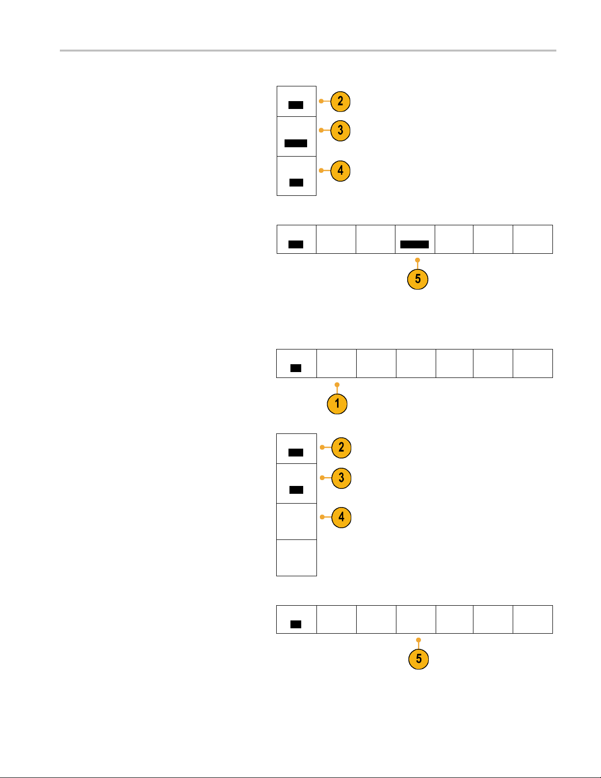
Acquire the Sign
al
2. Turn multipur
pose knob a to select the
channel connected to the CAN bus source.
3. Turn multipurpose knob a to select the type of
CAN signal to match the source of the CAN
bus: CAN_H, C
AN_L, Rx, Tx, or Differential.
4. Turn multipurpose knob a to set the Sample
Point from 5
% to 95% of the position within
the bit period or the unit interval.
5. Push Bit Rate and turn multipurpose knob a
to select f
rom the list of predefined bit rates.
Alternately, you can set the bit rate to a
specific value. To do so, select Custom, and
then turn
multipurpose knob b to set the bit
rate from 10000 to 1000000.
To acqui
re data from a LIN bus, you need to also set up these items:
1. If you selected LIN , push Define Inputs and
the desired side-bezel menu choices.
CAN Input
(a) 1
Signal
Type
CAN_H
Sample
Point
50%
Bus
CAN
Bus
LIN
Define
Inputs
Define
Inputs
Thresholds Bit Rate
500 Kbps
Thresholds
Configure
B1 Label
CAN
B1 Label
LIN
Bus
Display
Bus
Display
Event
Tab l e
Event
Table
2. Turn multipurpose knob a to select the
channel connected to the LIN bus source.
3. Turn multipurpose knob a to set the Sample
Point from 5% to 95% of the position within
the bit period or the unit interval.
4. Select the Polarity to match the LIN bus
being acquired.
5. Push Configure and the desired side-bezel
menu choices.
LIN Input
(a) 1
Sample
Point
50%
Polarity
Normal
(High=1)
Polarity
Inverted
(High=0)
Bus
LIN
Define
Inputs
Thresholds
Configure
B1 Label
LIN
Bus
Display
Event
Table
DPO2000 and MSO2000 Series Oscilloscopes User Manual 57
Page 78

Acquire the Sign
al
6. Push Bit Rate,
and turn multipurpose knob a
to select from the list of predefined bit rates.
Alternately, you can set the bit rate to a
specific value
.Todoso,selectCustom,and
Bit Rate
(a)
19.2K bps
then turn multipurpose knob b to set the bit
rate from 800 bps to 100000 bps.
7. Push LIN Standard, and turn multipurpose
knob a to select the appropriate standard.
8. Push Includ
e Parity Bits with Id to select
whether or not to include parity bits.
LIN
Standard
v1.x
Include
Parity Bits
with Id
Off
On|
To acquire data from a RS-232 bus, you need to also set up these items:
1. If you sel
ected RS-232, push Configure and
the desired side-bezel menu choices.
Use the si
de-bezel menu to configure the
Bus
RS-232
Define
Inputs
bus. Use Normal polarity to trigger on
RS-232 signals and Inverted polarity to
on RS-422, RS-485, and UART
trigger
signals.
Thresholds
Configure
9600-8-N
B1 Label
RS-232
Bus
Display
Event
Tabl e
58 DPO2000 and MSO2000 Series Oscilloscopes User Manual
Page 79
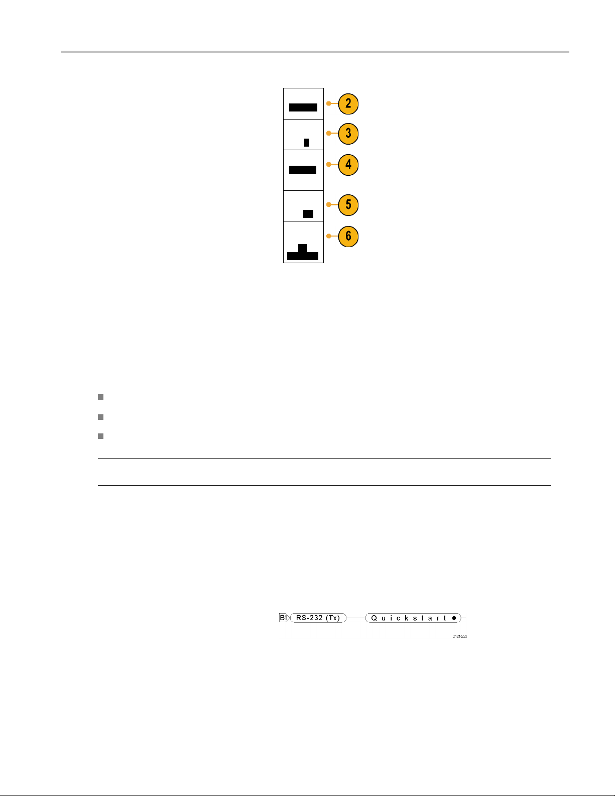
Acquire the Sign
al
2. Push Bit Rate,
and turn multipurpose knob a
to select the appropriate bit rate.
3. Push Data Bits
and select the number to
match the bus.
4. Push Parity a
nd turn multipurpose knob a to
match the polarity used by the bus as None,
Bit Rate
9600 bps
Data Bits
7|
8
Parity
(a) None
Odd, or Even.
5. Push Packets and select On or Off.
6. Turn multip
urpose knob a to select an
end-of-packet character.
Packets
On|
Off
End of
Packet
0A
(Linefeed)
RS-232 decoding displays a stream of bytes.
You can organize the stream into packets
with an end
Physical
-of-packet character
Layer Bus Activity
Oscilloscope waveform traces from analog channels 1 to 4, digital channels D15 to D0, and the traces you see when you
choose to display a bus always show the physical layer bus activity. In the physical layer display, bits that were transmitted
earlier are to the left, and bits that were transmitted later are to the right.
I2C, and CAN buses transmit the MSB (most significant bit) first
SPI buses do not specify a bit order
RS-232 and LIN buses transmit the LSB (least significant bit) first
NOTE. The oscilloscope displays the decode traces and event tables for all buses with the MSB on the left and LSB
on the right.
For example, an RS-232 signal (after the start bit) might be high, high, high, low, high, low, low, and high. Since the RS-232
protocol uses high for z ero and low for one, this value would be 0001 0110.
Since the decode displays the MSB first, the oscilloscope reverses the order of the bits and displays 0110 1000. If the bus
display is set to hex, the value displays as 68. If the bus display is set to ASCII, the value displays as h.
RS-232
If you de fi ned an end-of-packet character
to use for RS-232 decoding, the stream of
bytes will be displayed as packets.
DPO2000 and MSO2000 Series Oscilloscopes User Manual 59
Page 80

Acquire the Sign
al
When decoding an RS-232 bus in ASCII
mode, a large dot indicates that the value
represents a c
ASCII range.
haracter outside the printable
SettingUpDigitalChannels(MSO2000SeriesOnly)
Use front-panel buttons and knobs to set up your oscilloscope to acquire signals using the digital channels available
only on MSO2000 models.
1. Connect the P6316 digital probe to the input
signal source.
2. Connect the ground lead or leads to the
circuit ground.
You can connect one or two of the common
ground leads for each group of 8 channels
(wires).
3. If needed, connect the appropriate grabber
for each channel to the probe tip.
4. Connect each channel to the desired circuit
test point.
5. Push the D15 - D0 front panel button to
display the menu.
60 DPO2000 and MSO2000 Series Oscilloscopes User Manual
Page 81

Acquire the Sign
al
6. Push the lower
access the D15 - D0 On or Off menu.
7. Turn multipu
the list of digital channels. Turn multipurpose
knob b to position the selected channel.
As you posit
on the display, the oscilloscope groups the
channels, and adds the group to the pop-up
list. You c
move all the channels in the group instead
of individual channels.
8. Push the l
You can assign a different threshold value
to each pod.
9. Push the l
and create the label. You can create labels
through the front panel or with an optional
USB keyb
Channels and Buses.)
10. Push the lower-bezel Height button
edly to set the signal height. You only
repeat
need to do this once to set the height for all
of the digital channels.
-bezel D15 - D0 button to
rpose knob a to scroll through
ion channels close to each other
an select the group from the list to
ower-bezel Thresholds button.
ower-bezel Edit Labels button
oard. (See page 42, Labeling
D15–D0
On/Off
Thresholds Edit Labels Height
S |ML
Quick Tip
Use the zoom feature to see multiple cycles of the signal in the upper part, and a single cycle in the lower part of the
display. (See page 103, Using Wave Inspector to Manage Long Record Length Waveforms.)
The lead for each digital channel has a color-coded band for easy identification. The ground leads are shorter and
have black wires.
Digital channels store a high or low state for each sample. The threshold that separates a high from a low can be set for
all the channels in GROUP 1 or in GROUP 2. The threshold can not be set for individual channels.
Reducing Unwanted Noise With FilterVu
You can use FilterVu to filter unwanted noise from your signal and still capture glitches. The oscilloscope does this by
perimposing a filtered foreground waveform over a glitch capture background waveform.
su
e filtered waveform uses a variable low-pass filter to block out noise, yielding a cleaner waveform. When the noise filter is
Th
adjusted to the minimum bandwidth setting, no more than 1% of high-frequency content that could cause the oscilloscope
to alias will pass through the filter.
DPO2000 and MSO2000 Series Oscilloscopes User Manual 61
Page 82

Acquire the Sign
The glitch capture waveform shows signal details up to the full bandwidth of the oscilloscope. The oscilloscope captures
pulses as narro
When your signal is filtered, the glitch capture waveform changes color to distinguish it from the filtered waveform. When
the signal is filtered, you can independently adjust the intensity of the glitch capture waveform. When the signal is not
tered, the intensity of the glitch capture waveform depends on the overall intensity (under the Intensity button on the
fil
oscilloscope front panel).
FilterVu, Bandwidth Limit, and Averaging
You can use FilterVu, Bandwidth Limits, or Average mode to reduce noise in your signal. Each has benefits.
NOTE. FilterVu does not apply to triggering. To reduce the effects of noise on your signal while triggering, use Bandwidth
Limits or use Coupling settings.
Use FilterVu when you want to do the following:
Adjust your filter frequency with more granularity than the Bandwidth Limit provides.
Adjust all channels to the same frequency.
Acquire a non-repetitive or a single-shot signal.
al
w as 5 ns, using peak detect min/max sampling.
Use Bandwidth Limit w hen you want to do the following:
Filter only one channel.
Trigger on a filtered signal.
Acquire a non-repetitive or a single-shot signal.
Use Average mode when you want to do the following:
Acquire a repetitive signal.
Noise on your signal is random (not correlated with the trigger).
Increase the vertical precision of your acquisition.
NOTE. You can use FilterVu with Bandwidth Limit. You cannot use FilterVu with Average mode.
Quick Tips
You can choose to save to a file with full resolution (every point that was captured) or reduced resolution (fewer points).
When your signal is filtered, only the reduced-resolution waveform is guaranteed to be filtered to the chosen frequency.
Sometimes, the filter is unable to produce a full-resolution waveform with a frequency as low as the chosen frequency.
The frequency of the full-resolution waveform is shown in the saved file.
When the glitch capture background is on, a saved waveform file includes both the foreground and the background data.
Reference waveforms can be filtered; the chosen noise filter frequency also applies to references. Reference waveforms
also have a glitch capture background.
Reference waveforms are always saved at full resolution. Unlike saving a waveform to a file, there is no reduced
resolution option.
62 DPO2000 and MSO2000 Series Oscilloscopes User Manual
Page 83

When the signal is not filtered, most measurements are taken on the foreground waveform. The min, max, and
peak-to-peak m
largest amplitudes in the waveform.
When the signal is filtered, all measurements are taken from the filtered waveform.
Dual-waveform math can be filtered; the chosen noise filter frequency also applies to math. Dual-waveform math
does not have a glitch capture background.
Search uses the glitch capture background, when available. This lets you better search for spikes and other anomalies.
Serial bus decode uses a full-resolution sample (foreground) waveform. When filtering is active, that waveform might not
be filtered t
Using FilterVu
By default, the noise filter cutoff frequency is set to the full bandwidth of the oscilloscope when you use FilterVu. To invoke
the variable low-pass filter (noise filter), turn the multipurpose knob counterclockwise. The oscilloscope passes lower
frequency signals which results in a cleaner-looking wav eform. The noise frequency readout displays frequencies that
the oscilloscope includes in the foreground waveform. The oscilloscope displays higher frequency components in the
background waveform, up to the bandwidth of the DPO2000 or MSO2000 model.
easurements are taken on the glitch capture background, because they measure the smallest and
o the chosen frequency.
Acquire the Sign
al
NOTE. The oscilloscope always displays the noise filter cutoff frequency in the upper right part of the screen. The cutoff
frequency reflects the -3 dB point.
1. Push the FilterVu button.
2. Turn multipurpose knob a to adjust the
Noise Filter (Foreground) value.
DPO2000 and MSO2000 Series Oscilloscopes User Manual 63
Page 84

Acquire the Sign
al
Noise Filter (Fore-
ground)
(a)
200MHz
3. Push Glitch C
apture Background to turn
off the background waveform that contains
the higher frequency components of the
signal.
With Glitch Capture set to Off, the
oscilloscope displays only the noise filter
(foregroun
d) waveform.
4. With Glitch Capture set to On, turn
multipurp
ose knob b to adjust the intensity of
the Glitch Capture (background) waveform.
You c an only adjust the intensity when
.
filtering
Glitch
Capture
Back-
ground
On |Off
Back-
ground
Intensity
Auto
64 DPO2000 and MSO2000 Series Oscilloscopes User Manual
Page 85
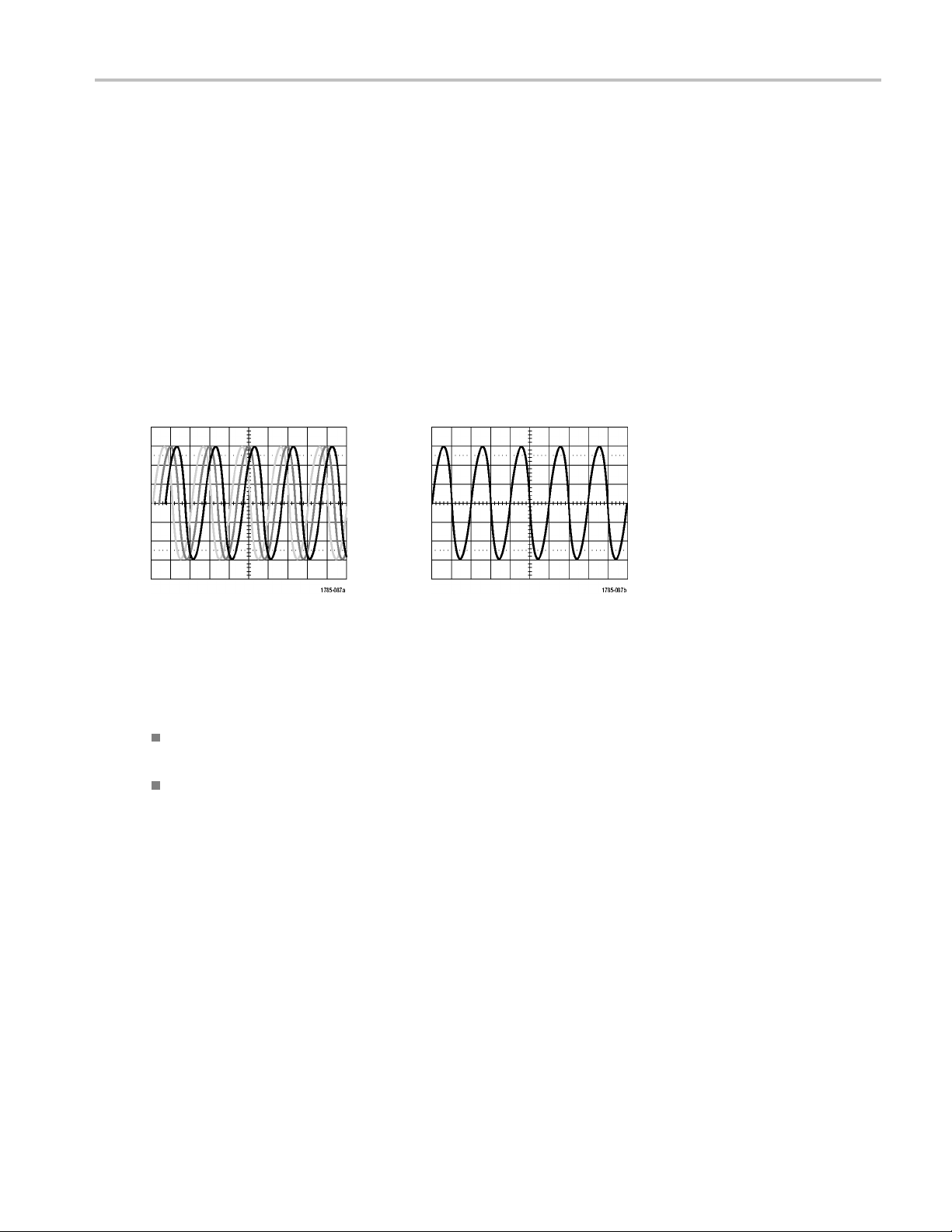
Trigger Setup
This section contains concepts and procedures for setting up the oscilloscope to trigger on your signal.
Triggering Concepts
Trigger Event
The trigger event establishes the time-reference point in the waveform record. All waveform record data is located in time
with respect to that point. The oscilloscope continuously acquires and retains enough sample points to fill the pretrigger
portion of the waveform record. That is the part of the waveform that is displayed before, or to the left of, the triggering
event on screen. When a trigger event occurs, the oscilloscope starts acquiring samples to build the posttrigger portion of
the waveform record, that is, the part displayed after or to the right of the trigger event. After a trigger is recognized, the
oscilloscope will not accept another trigger until the acquisition is complete and the holdoff time has expired.
Trigger Setup
Untrigg
ered display
Trigger
ed display
Trigger Modes
The trigger mode determines how the oscilloscope behaves in the absence of a trigger event:
Normal trigger mode enables the oscilloscope to acquire a waveform only when it is triggered. If no trigger occurs, the
last waveform record acquired remains on the display. If no last waveform exists, no waveform is displayed.
Auto trigger mode enables the oscilloscope to acquire a waveform even if a trigger does not occur. Auto mode uses
a timer that starts when the acquisition is started, and the pretrigger information is obtained. If a trigger event is not
detected before the timer times out, the oscilloscope forces a trigger. The length of time it waits for a trigger event
depends on the time base setting.
Auto mode, when forcing triggers in the absence of valid triggering events, does not synchronize the waveform on the
display. The waveform will appear to roll across the screen. If valid triggers occur, the display will become stable.
You can also force the oscilloscope to trigger. To do so, push the front-panel Force Trig button.
DPO2000 and MSO2000 Series Oscilloscopes User Manual 65
Page 86

Trigger Setup
Trigger Holdoff
Adjust holdof
when the oscilloscope is triggering on
undesired trigger events.
Trigger holdo
since the oscilloscope does not recognize
new triggers during the holdoff time. When
the oscillos
it disables the trigger system until acquisition
is complete. In addition, the trigger system
remains dis
that follows each acquisition.
f to obtain stable triggering
ff can help stabilize triggering,
cope recognizes a trigger event,
abled during the holdoff period
Holdoffs
Trigger Coupling
Trigger coupling determines what part of the signal is passed to the trigger circuit. Edge triggering can use all available
coupling types: DC, Low Frequency Rejection, High Frequency Rejection, and Noise Rejection. All other trigger types
use DC coupling only.
The cutoff frequency for low frequency rejection is 65 kHz. The cutoff frequency for high frequency rejection is 85 kHz.
Horizontal Position
When Delay Mode is on, use horizontal
position to acquire waveform detail in a
region that is separated from the trigger
location by a significant interval of time.
66 DPO2000 and MSO2000 Series Oscilloscopes User Manual
Page 87

Trigger Setup
1. Adjust the position (delay) time by
rotating the Horizontal Position knob.
2. Turn the horizontal Scale knob to acquire
the detail th
position (delay) expansion point.
The part of the record that occurs before the trigger is the pretrigger portion. The part that occurs after the trigger is the
posttrigger portion. Pretrigger data can help you troubleshoot. For example, to find the cause of an unwanted glitch in
your test circuit, you can trigger on the glitch and make the pretrigger period large enough to capture data before the
glitch. By analyzing what happens before the glitch, you may uncover information that helps you find the s ource of the
glitch. Alternatively, to see what is happening in your system as a result of the trigger event, make the posttrigger period
large enough to capture data after the trigger.
at you need around the
Slope and Level
The slope control determines whether the
oscilloscope finds the trigger point on the
rising or the falling edge of a signal.
The level control determines where on that
edge the trigger point occurs.
The oscilloscope provides a long horizontal
bar or bars across the graticule to temporarily
show the trigger level.
1. Turn the front-panel Trigger Level knob
just the trigger level without going
to ad
to a menu.
2. Push the Force Trig button to force the
oscilloscope to trigger.
DPO2000 and MSO2000 Series Oscilloscopes User Manual 67
Page 88

Trigger Setup
Choosing a Trigger Type
To select a trigger:
1. Push Trigger Menu.
2. Push Ty pe to bring up the list of Trigger
Types.
NOTE. The bus trigger in the MS O 2000 series
works on parallel buses even without an
application module. Using the bus trigger on
other buses requires use of the DPO2EMBD,
DPO2AUTO, or DPO2COMP application
module.
3. Turn multipurpose knob a to select the
desired trigger type.
The trigger types are: Edge, Pulse Width,
Runt, Logic, Setup & Hold, Rise/Fall Time,
Video, and Bus.
4. Complete the trigger setup using the
lower-bezel menu controls displayed for
the trigger type. The controls to set up the
trigger vary depending on the trigger type.
Selecting Triggers
Trigger type Trigger conditions
Edge
Type
Edge
Source1Coupling
DC
Slope
Level
100 mV
Trigger on a rising or falling edge, as defined by the
slope control. Coupling choices are DC, LF Reject, HF
Reject, and Noise Reject.
Edge triggers are the simplest and most commonly
used trigger type, with both analog and digital signals.
An edge trigger event occurs when the trigger source
passes through a specified voltage level in the specified
direction.
Mode
Auto
& Holdoff
68 DPO2000 and MSO2000 Series Oscilloscopes User Manual
Page 89
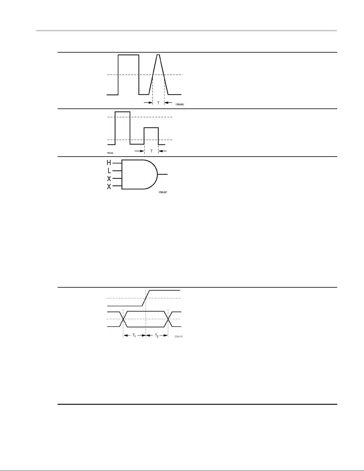
Trigger Setup
Trigger type Trigger conditions
Pulse Width Trigger on pulses that are less than, greater than, equal
to, or not equal to a specified time. You can trigger on
positive or n e
primarily used on digital signals.
Runt Trigger on a pulse amplitude that crosses one threshold
but fails to c
the first. You can detect positive or negative (or either)
runts, or only those wider than, less than, greater than,
equal to, or
are primarily used on digital s ignals.
gative pulses. Pulse width triggers are
ross a second threshold before recrossing
not equal to a specified width. Runt triggers
Logic
Setup and Hold Trigger when a logic data input changes state inside of
Trigger when all channels transition to the specified
state. Use multipurpose knob a to select a channel.
Push the appropriate side-bezel button to set that
channel’s state to High (H), Low (L),orDon’t Care (X).
Use the Clock side-bezel button to enable clocked
(state) triggering. You can have at most a single clock
channel. Push the Clock Edge bottom bezel button to
change the polarity of the clock edge. Turn off clocked
triggering and return to unclocked (pattern) triggering by
selecting the clock channel and setting it to high, low,
or don’t care.
For unclocked triggering, by default, triggering occurs
when the selected condition goes true. You can also
select triggering when the condition goes false, or
time-qualified triggering.
You can use up to 20 channels for a logic trigger
(4 analog and 16 digital) with MSO2000 series
oscilloscopes.
the setup or hold time relative to a clock edge.
Setup is the amount of time that data should be stable
and not change before a clock edge occurs. Hold is the
time that data should be stable and not change after
a clock edge occurs.
MSO2000 series oscilloscopes are capable of multiple
channel Setup and Hold triggering, and can monitor
the state of an entire bus for setup and hold violations.
You can use up to 20 channels for a Setup and Hold
trigger (4 analog and 16 digital) with MSO2000 series
oscilloscopes.
Use the Clock side-bezel button to select the clock
channel. Use the Select control, Data,andNot used
buttons to select one or more channels you want to
monitor for setup and hold violations.
DPO2000 and MSO2000 Series Oscilloscopes User Manual 69
Page 90

Trigger Setup
Trigger type Trigger conditions
Rise/Fall Time Trigger on rise and fall times. Trigger on pulse edges
that traverse
rates than the specified time. Specify pulse edges as
positive or negative or either.
between two thresholds at faster or slower
Trigge
Video
Bus Trigger on various bus conditions.
Trigger on specified fields or lines of a composite video
signal. Only
Trigger on NTSC, PAL, or SECAM. Works with
Macrovision signals.
2
C requir
I
SPI requires a DPO2EMBD module.
CAN requires a DPO2AUTO module.
LIN requi
RS-232, RS-422, RS-485, and UART require a
DPO2COMP module.
Paralle
(See page 14, Application Module Free Trial.)
composite signal formats are supported.
es a DPO2EMBD module.
res a DPO2AUTO module.
l requires an MSO2000 series oscilloscope.
ring on Buses
You can use your oscilloscope to trigger on CAN, I2C, SPI, RS-232, RS-422, RS-485, UART, and LIN buses, if you have the
appropriate DPO2AUTO, DPO2EMBD, or DPO2COMP application module installed. The MSO2000 series can trigger on
parallel buses without an application module. The oscilloscope can display both physical layer (as analog waveforms) and
protocol level information (as digital and symbolic waveforms).
To set up the bus trigger:
1. If you have not already defined your bus
using the front-panel B1 and B2 buttons, do
so now. (See page 51, Setting Up a Serial
or Parallel Bus.)
2. Push Trigger Menu.
70 DPO2000 and MSO2000 Series Oscilloscopes User Manual
Page 91

Trigger Setup
3. Push Type.
4. Turn multipur
pose knob a to scroll through
the list of trigger types until you select Bus.
5. Push Source Bus and turn multipurpose
knob a to scr
oll through the source bus side
menu until you select the bus that you want
to trigger on.
6. Push Trigger On and turn multipurpose
knob a to scroll through the side-bezel
menu unti
l you select the desired trigger on
feature.
If you are using the parallel bus trigger, you
can trigg
er on a binary or hex data value.
Push the lower-bezel Data button and enter
the parameters of interest with multipurpose
knobs a a
IfyouareusingtheI
nd b.
2
C bus trigger, you
can trigger on Start, Repeated Start,
Stop, M
issing Ack, Address, Data,or
Address/Data.
If you are using the SPI bus trigger, you can
ronSS Active, MOSI, MISO,orMOSI
trigge
&MISO.
If you are using the CAN bus trigger, you can
er on Start of Frame, Type of Frame,
trigg
Identifier, Data, Id & Data, End of Frame,
Missing Ack,orBit Stuffing Error.
Type
Bus
B1 (I2C)
B2
(Parallel)
Source
Bus
B1 (I2C)
Trigger On
Address
Address
07F
Direction
Write
Mode
Auto
& Holdoff
If you are using the RS-232 bus trigger, you
can trigger on Tx Start Bit, Rx Start Bit, Tx
f Packet, Rx End of Packet,Tx Data,
End o
Rx Data, Tx Parity Error,orRx Parity
Error.
If you are using the LIN bus trigger, you
can trigger on Sync, Identifier, Data, Id
ta,Wakeup Frame, Sleep Frame,or
&Da
Error.
DPO2000 and MSO2000 Series Oscilloscopes User Manual 71
Page 92

Trigger Setup
7. If you are setting up an I2C trigger and have
made a Trigger On selection of Address
or Address/Da
Address button to access the I
ta, push the lower-bezel
2
C Address
side-bezel menu.
Push the side
-bezel Addressing Mode
button and select 7bitor 10 bit. Push
the side-bezel Address button. Enter
the address p
arameters of interest with
multipurpose knobs a and b.
Then push the lower-bezel menu Direction
button and s
elect the direction of interest:
Read, Write,orRead or Write.
If you have
made a Trigger On selection
of Data or Address/Data, push the
lower-bezel Data button to access the I
Data side
-bezel menu.
2
C
Push the Number of Bytes button and
enter the number of bytes with multipurpose
knob a.
Push the side-bezel Addressing Mode
button and select 7bitor 10 bit. Push
-bezel Data button. Enter the data
the side
parameters of interest with multipurpose
knobs a and b.
e information on the I
For mor
2
C address
formats, refer to item 2 under Setting Up
Bus Parameters.
8. If you are setting up an SPI trigger and have
made a Trigger On selection o f MOSI or
push the lower-bezel Data button,
MISO,
push the side-bezel MOSI (or MISO) button,
and enter the data parameters of interest
multipurpose knobs a and b.
with
Then push the Number of Bytes button and
enter the number of bytes with multipurpose
a.
knob
If you select MOSI & MISO, push the
lower-bezel Data button and enter the
ameters of interest in the side-bezel
par
menus.
72 DPO2000 and MSO2000 Series Oscilloscopes User Manual
Page 93

9. If you are setting up a CAN trigger and have
made a Trigger On selection of Type of
Frame, push th
button, and select Data Frame, Remote
Frame, Error Frame, or Overload Frame.
If you have ma
Identifier, push the lower-bezel Identifier
button, and select a Format. Then push the
Identifier si
binary or hex value with multipurpose knobs
a and b.
Push the low
and select the direction of interest: Read ,
Write,orRead or Write.
If you have
of Data. Push the lower-bezel Data button
and enter the parameters of interest with
multipurp
10. If you are setting up an RS-232 trigger and
have made
Data or Rx Data, push the lower-bezel Data
button.
Push the
enter the number of bytes with multipurpose
knob a.
Push th
the parameters of interest with multipurpose
knobs a and b.
e lower-bezel Frame Type
de a Trigger On selection of
de-bezel button, and enter a
er-bezel menu Direction button
made a Trigger On selection
ose knobs a and b.
a Trigger On selection of Tx
Number of Bytes button and
e side-bezel Data button, and enter
Trigger Setup
11. If you are setting up an LIN trigger and
have made a Trigger On selection of
ifier, Data
Ident
the lower-bezel Identifier or Data buttons
and enter the parameters of interest on the
lting side-bezel menu.
resu
If you have made a Trigger On selection
of Error, push the lower-bezel Error Type
on and enter the parameters of interest
butt
on the resulting side-bezel menu.
,orIdentifier & Data, push
I2C, SPI, CAN, and LIN Bus Trigger Data Matching
Rolling window byte matching for I2C, and SPI. To use a rolling window to trigger on data, you define the number
of bytes to match. Then the oscilloscope uses a rolling window to find any match within a packet, with the window rolling
one byte at a time.
For example, if the number of bytes is one, the oscilloscope will attempt to match the first byte, second byte, third, and so
on within the packet.
If the number of bytes is two, the oscilloscope will try to match any two consecutive bytes, such as one and two, two and
three, three and four, and so on. If the oscilloscope finds a match, it will trigger.
DPO2000 and MSO2000 Series Oscilloscopes User Manual 73
Page 94
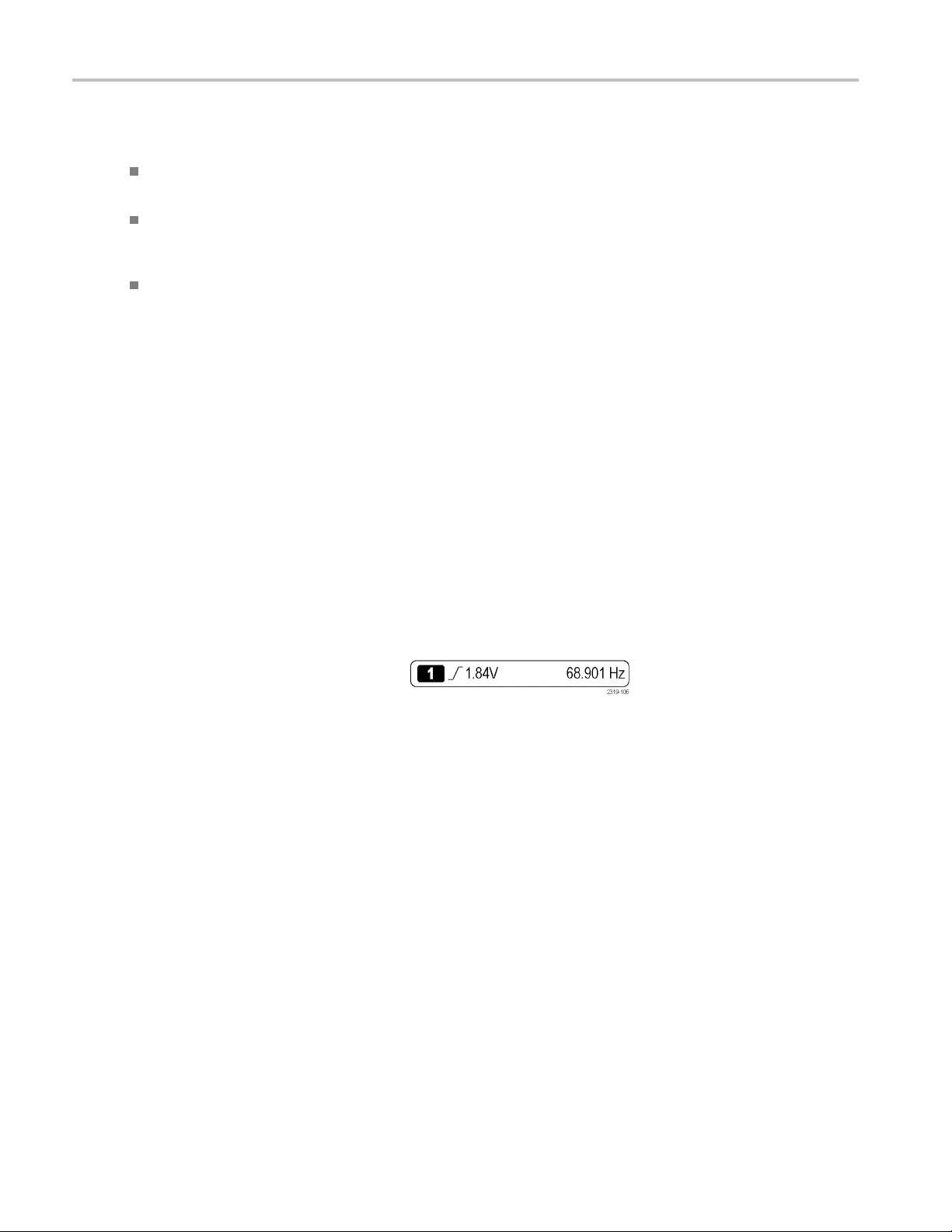
Trigger Setup
Specific byte matching (non-rolling window matching for a specific position in the packet) for I2C, SPI,
and CAN.
For I2C and SPI
mask the bytes that you are not interested in.
For I2C, push the lower-bezel Trigger On to trigger on Address/Data. Push Ad dr ess . On the side-bezel menu, push
Address, and turn multipurpose knobs a and b as needed. Set the address to don’t cares (X) if you want to mask the
address. The
For CAN, trig
the first byte. Set the number of bytes to match the number of bytes of interest. Use the data qualifier to perform: =,
!=, <, >, >=, and <= operations. Triggering on identifier and data always matches the identifier and data selected by
the user, wi
You can
trigger on a specificbyteforI
, enter the number of bytes to match the number of bytes in the signal. Then use don’t cares (X) to
data will be matched starting at the first byte without using a rolling window.
gering occurs when the user-selected data input matches the data and qualifier in the signal starting at
th the data starting at the first byte. No rolling window is used.
2
C, SPI, and CAN in several ways:
RS-232 Bus Trigger Data Matching
You can trigger on a specific data value for RS-232 bytes. If you d efined an end-of-packet character to use for RS-232 bus
decoding, you can use the same end-of-packet character as a data value for trigger data matching. To do so, choose the Tx
End of Packet or the Rx End of Packet character as the Trigger O n selection.
ParallelBusTriggerDataMatching
Optimum
(MSO2000 series only).
parallel bus trigger performance is achieved by using only analog channels or only d igital channels
Checking Trigger Settings
kly determine the settings of some
To quic
key trigger parameters, check the Trigger
readout at the bottom of the display. The
uts differ for edge and the advanced
reado
triggers.
1. Trigger source = channel 1.
2. Trigger slope = rising.
3. Trigger level = 1.84 V.
4. 6-Digit Trigger Frequency Readout =
68.901 Hz.
Edge trigger readout
74 DPO2000 and MSO2000 Series Oscilloscopes User Manual
Page 95

StartingandStoppinganAcquisition
After you have defined the acquisition and trigger parameters, start the acquisition with Run/Stop or Single.
Push Run/Stop to start acquisitions.
The oscilloscope acquires repeatedly
until you push the button again to stop
the acquisition.
Push Single to take a single acquisition.
Single sets the trigger mode to Normal
for the single acquisition.
Trigger Setup
DPO2000 and MSO2000 Series Oscilloscopes User Manual 75
Page 96

Display Wavefor
mData
Display Wavef
orm Data
This section contains concepts and procedures for displaying the acquired waveform.
Adding and Removing a Waveform
1. To add or remove a waveform from
the display, push the corresponding
front-panel channel button or the D15-D0
button.
You can use the channel as a trigger
source whether or not it is displayed.
Setting the Display Style and Persistence
1. To set the display style, push Acq uire.
2. Push Waveform Display.
Average
Off
Record
Length
100k
Delay
On|Off
Set Hor
Position to
0s
Wavefo
Display
rm
iz.
XY Display
Off
Acquisition
Details
76 DPO2000 and MSO2000 Series Oscilloscopes User Manual
Page 97
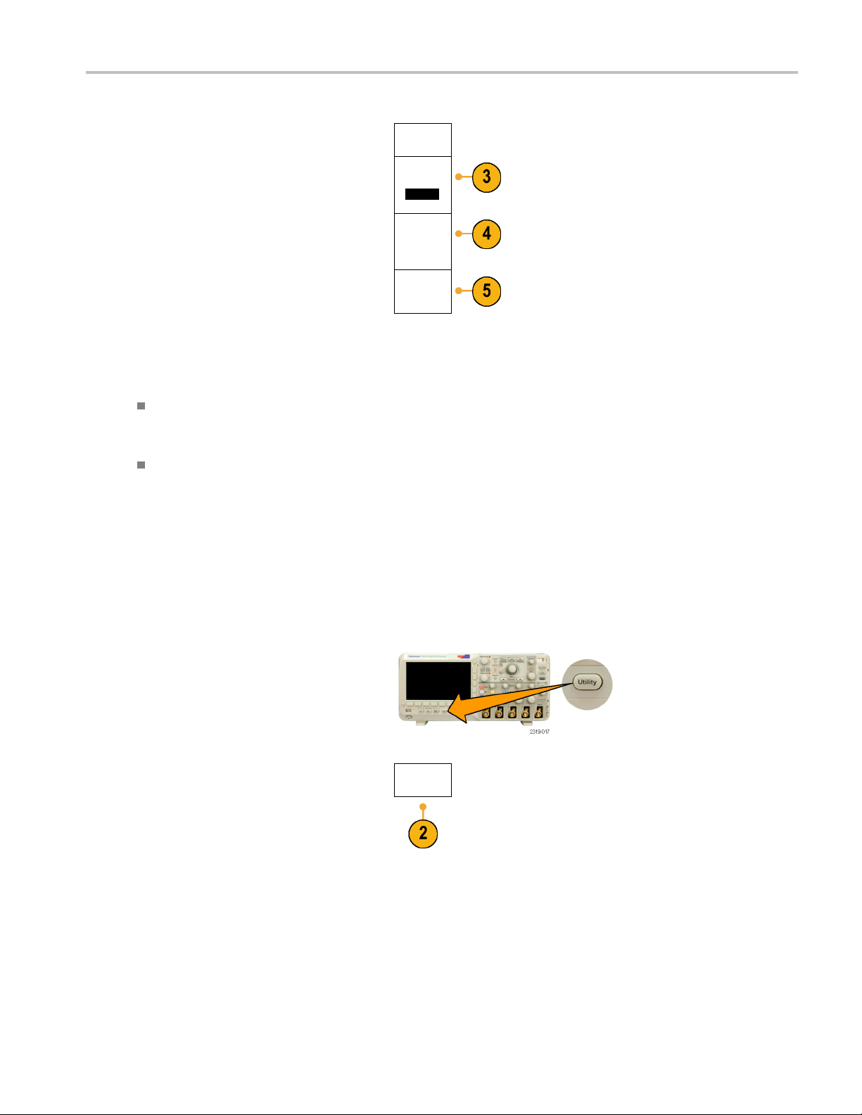
Display Wavefor
Waveform
Display
3. Push Persist Time, and turn multipurpose
knob a to have waveform data remain on
screen for a us
er-specified amount of time.
4. Push Set to Auto to have the oscilloscope
automatical
ly determine a persistence time
Persist
Time
(a) Auto
Set to Auto
for you.
5. Push Clear P
persistence information.
ersistence to reset the
Clear Per-
sistence
Quick Tips
Variable persistence accumulates sampled waveform points for a specified time interval. Each sampled waveform
decays independently according to the time interval. Use variable persistence for displaying infrequently appearing
signal anomalies, such as glitches.
Infinite persistence continuously accumulates record points until you change one of the acquisition display settings. Use
infinite persistence for displaying uniqu e signal anomalies, such as glitches.
mData
XY Display Mode
The XY Display mode graphs the data in fixed pairs of waveforms against one another. You can use CH1 versus CH2, and
REF1 versus REF2. On four-channel models, you can also use CH3 versus CH4.
ng the Graticule Style
Setti
1. To s et
2. Push Utility Page.
the graticule style, push Utility.
Utility
Pag
e
DPO2000 and MSO2000 Series Oscilloscopes User Manual 77
Page 98

Display Wavefor
mData
3. Turn multipur
pose knob a and select
Display.
4. Push Graticule from the lower-bezel menu.
5. Select the desired style from the resulting
side-bezel menu.
Use the Full
graticule for quick estimates of
waveform parameters.
Use the Grid graticule for full-screen
measureme
nts with cursors and automatic
readouts when cross hairs are not needed.
Use the Cross Hair graticule for making
quick est
imates of waveforms while leaving
more room for automatic readouts and other
data.
Use the F
rame graticule with automatic
readouts and other screen text when display
features are not needed.
Utility
Page
Display
Backlight
Intensity
High
Graticule
Full
Screen
Annotation
Quick Tips
n display IRE and mV graticules. To do this, set the trigger type to video and set the vertical scale to
You c a
143 mV/division. (The 143 mV/division selection is available in the coarse vertical scale settings for the channel when
you set the trigger type to video.) The oscilloscope will automatically display the IRE graticule for NTSC signals, and the
ticule for other video signals (PAL, SECAM, and custom).
mV gra
Setting the LCD Backlight
1. Push Utility.
2. Push Utility Page.
Utility
Page
78 DPO2000 and MSO2000 Series Oscilloscopes User Manual
Page 99

Display Wavefor
mData
3. Turn multipur
4. Push Backligh
5. Select the intensity level from the resulting
Setting W
1. Push the front-panel Intensity button.
pose knob a and select
Display.
t Intensity.
side-bezel
menu. Choices are: High,
Medium, and Low.
aveform Intensity
Utility
Page
Display
Backlight
Intensity
High
Medium
Low
Backlight
Intensity
High
Graticule
Full
Screen
Annotation
This will bring up the intensity r eadout on
lay.
the disp
2. Turn multipurpose knob a to select the
desired intensity for the waveform.
3. Turn multipurpose knob b to select the
desired intensity for the graticule.
DPO2000 and MSO2000 Series Oscilloscopes User Manual 79
Page 100

Display Wavefor
mData
4. Push Intensity
readout from the display.
again to clear the i ntensity
Scaling and Positioning a Waveform
Use the horizontal controls to adjust the time base, adjust the trigger point, and to examine waveform details more closely.
You can also use the Wave Inspector Pan and Zoom controls to adjust the display of waveforms. (See page 103, Using
Wave Inspector to Manage Long Record Length Waveforms.)
Original waveform Scaled horizon tally Positioned horizontally
Use the vertical controls to select waveforms, adjust the waveform vertical position and scale, and set input parameters.
Push a channel menu button (1, 2, 3,or4) as many times as needed and the associated menu items to select, add, or
remove a waveform.
Original waveform Scaled vertically Positioned vertically
Quick Tips
Preview. If you change the Position or Scale controls when the acquisition is stopped or when it is waiting for the next
trigger, the oscilloscope rescales and repositions the relevant waveforms in response to the new control settings. It
simulates what you will see when you next push the RU N button. The oscilloscope uses the new settings for the next
acquisition.
You may see a clipped waveform if the original acquisition went off the screen.
The math waveform, cursors, and automatic measurements remain active and valid when using preview.
80 DPO2000 and MSO2000 Series Oscilloscopes User Manual
 Loading...