

Tektronix 7018-S, 7018-C Instruction Manual

Models 7018-S and 7018-C
28-Channel3-Pole Multiplexer Cards
Instruction Manual
Contains Operating and Servicing Information

WARRANTY
Kcithley Instruments, Inc. warrants this product to be free from defects in material and workmanship for a period of I year
from date of shipment.
Keithley Instruments, Inc. warrants the following items for 90 days from the date of shipment: probes, cables, rechargeable
baitcries, diskettes, and documentation.
During the warranty period, we will, at our option, either repair or replace any product that proves to be defective.
To exercise this warranty, write or call your local Keithley representative, or contact Keithlcy headquarters in Cleveland, Ohio.
You will be given prompt assistance and return instructions. Send the product, transportation prepaid, to the indicated sewice
facility. Repairs will be made and the product returned, transportation prepaid. Repaired or replaced products arc warranted for
the balance of the original warranty period, or at least 90 days.
LlMlTATlON OF WARRANTY
This warranly does not apply to defects resulting from product modification without Keithley’s express written consent, or
misuse of any product or part. This warranty also does not apply to fuses, software, non-rechargeable batteries, damage from
battery leakage, or problems arising from normal wear or failure to follow instructions.
THIS WARRANTY IS IN LIEU OF ALL OTIIER WARRANTIES, EXPRESSED OR IMPLIED, INCLUDING ANY
IMPLIED WARRANTY OF MERCHANTABILITY OR FITNESS FOR A PARTICULAR USE. THI? REMEDIES I’ROVIDED HEREIN ARE BUYER’S SOLE AND EXCLUSIVE REMEDIES.
NEITHER KEITHLEY INSTRUMENTS, INC. NOR ANY OF ITS EMPLOYEES SHALL BE LIABLE FOR ANY DIRECT,
INDIRECT, SPECIAL, INCIDENTAL OR CONSEQUHNTIAL DAMAGES ARISING OUT OF THE USE OF ITS
INSTRUMENTS AND SOFI-WARE EVEN IF KEITHLEY INSTRUMENTS, INC., HAS BEEN ADVISED IN ADVANCE
OF THE POSSIBILITY OF SUCH DAMAGES. SUCH EXCLUDED DAMAGES SHALL INCLUDE, BUT ARE NOT LIMITED TO: COSTS OF REMOVAL AND INSTALLATION, LOSSES SUSTAINED AS THE RESULT OF INJURY TO ANY
PERSON, OR DAMAGE TO PROPERTY.
Kcithley Instruments, Inc. * 28775 Aurora Road - Cleveland, OH 44139 - 440-24X-0400 - Fax: 440-248-6168 9 http://www.kcithley.com

Models 7018-S and 7018-C
Instruction Manual
01993, Keithley Instruments, Inc.
All Rights Reserved
Cleveland, Ohio, U. 5. A.
First Printing, October 1993
Document Number: 7018-901-01 Rev. A

Manual Print History
The print history shown below lists the printing dates of all Revisions and Addenda created for this manual. The
Revision Level letter increases alphabetically as the manual undergoes subsequent updates. Addenda, which are
released between Revisions, contain important change information that the user should incorporate immediately
into the manual. Addenda are numbered sequentially. When a new Revision is created, all Addenda associated
with the previous Revision of the manual are incorporated into the new Revision of the manual. Each new Revision includes a revised copy of this print history page.
Revision A (Document Number 7018~901.01) October 19%

Safety Precautions
l‘hc following safciy prccaulions should hc ohscrvcd heforc using
this producl and any associated instrumcnlation. Although some in~mmxmis and accessories would normally hc used with non-hazardous voltages, thcrc are siluations whcrc hazardous conditions
may hc prcscnl.
This product is imended for USC by queiilicd pcrsonncl whn rcwg~
nix shock hazards and arc familiar with :hc safety prccaulions rc~
quired Lo avoid possihlc injury. Kcad tbc “peraiing informalion
carclully hefore using the pruducl.
The types “C product users arc:
Responsible body is lhc individual or group rcsponsihlc lor the USC
and mainlenancc or equipmcnl. r”r ensuring that the equipment is
operated within its specilicauons and “pcrating limits. and for cn~
swing lhal “pcratnrs arc adcquatcly waincd.
Operators us” the product for ils imendcd runclion. They must he
trained in clcctrical salety procedures and proper US” of lhc instrumcnt. They must hc protcctcd from electric shock and con&i wilb
hazardous live circuits.
Maintenance personnel perform routine proccdurcs on the producl
to keep it “pcrating, for example. setting the line vollagc or replacing consumahic materials. Maintenance proccdurcs arcdcscrihcd in
the manual. The proccdurcs cxplicidy stat” if ~hc opcralor may pcrSourm Ihem. Otherwise, they should bc pcrrormcd only by service
personnel.
Service personnel arc lraincd 1” work on live circuits. and pcrlurm
safe installations and repairs or
vice personnel may perform installation and service proccdurcs.
lixcrcise extreme caution when a shock hazard is prcscnt. Lcihal
vol~agc may be present on cable connector jacks or test Axturcs. The
American National Slandards lnstitule (ANSI) BIZBES thdl B shock
hazard exists when voltage levels grcatcr than 30V RMS. 42.4V
peak. or 60VDC arc prcsen~. A goud safety practice is to fx-
pect that hazardous vnltage is present in any un-
known circuit before measuring.
products.
Only properly trained scr-
The insmmcnt and accessories mu bc used in accordance with its
spccilicalions and operating inslrucLinns OT the safely of Ihc cquipmcnt may be impeircd.
Do ml exceed the maximum signal lcvcls ofthc inswmcnls and acccssorics, as defined in the specificaliuns and operating information, and as shown on Ihc insliumcnt OT test fixlurc panels, or
switching card.
The
WARNING
rcsul~ in persrmal injury or death. Always read the asocialed i&rmaCon very carefully bclore performing ~hc indicated procedure.
The
CAUTION
damage the inslrumcnl. Such damage may invatidaw the wananty.
Inavumenlalian and acccssorics shall nol hc connected 10 humans.
hcading in a manual explains dangcrs that might
hcading in a manual cxplains haxds Lhat could
When fuses BTC used in B produa, replace with same type and Ming
I’m continued prolcclion againsl fire harard.
Chassis conncclions must only be used as shield ConnecLions for
measuring circuits, NOT as safely carlh ground conneclions.
II you arc using a test fixurc, keep the lid closed while power is applied IO the device under test. Sale operalion rcquircs the use of a
lid intcriock.
Ira 0..
wire recommended in lhc user documentalion.
Then
rccr to the operating inslruclions located in lhc manual.
Then.
suc 1000 volls or more, including Lhc combined elfal of normal
and common mode voltages. Use standard safculy precautions 10
avoid pcrsonai contact with these vol~agcs.
ww is present mnm it LO sareely earth ground using the
symbol on an instrument indicates Hal the USCT should TC-
~ymhol on an instrumcnl shows Lhal il can swrcc OT mca-
Bcrorc pcribrming any maimcnancc, discoonccl the lint cord and
all test cahlcs.
To maintnin protcclion from elcc~ric shock and fire, rcplaccmcm
components in mains circuils, including lhc power Iransrormcr, test
leads, and input jacks, musL bc purchased from Kcithlcy Instrumcnts. Slandard rusts, wilh applicable national sarcly approvals,
may be used if the rating and type ari: Lhc same. Other components
that are not safety related may hc purchased from oLhcr suppliers as
long as Lhcy arc cquivalenl LO Ihc original componcnl. (Note thal set
lcclcd patts should bcpurchased only through Kcithlcy lnstrumenls
LO maintain accuracy and functiunalily of the producl.) If you arc
unsure about the applicabilily (11 a rcptaccmem componcm, call a
Kcithlcy Insmunents
To clean an insvumenl. USC B damp clolh or mild, water based
cleaner. Clean the exlerior of the instwmcnl only. Do not apply
ctcancr dircclly Lu Lhc instrument or aliow liquids LO enLcr or spilt
on the instrumenl. Products that consisL of a circuit board wilh no
case or chassis (c.g., dala acquisition board for installation into a
computer) should ncvcr rcquirc cleaning if handled according LO in-
sLruclions. I( Ihc board bccomcs cantaminaled and apcratian is a[-
f&cd, the board should be retuned Lo lhc factory for proper
clcaninglservicing.
dficc
for infonna~ion.
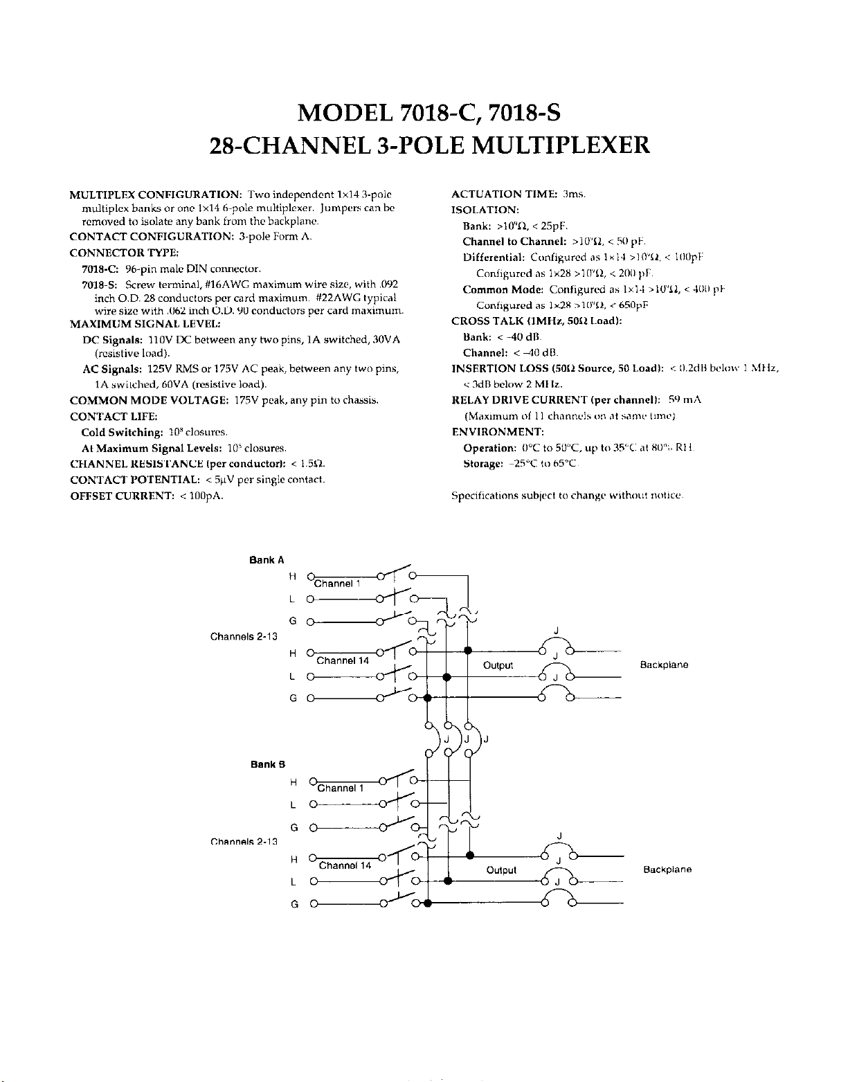
MODEL 7018-C, 7018-S
2%CHANNEL 3-POLE MULTIPLEXER
MULTIPLEX CONFIG”RATION: TWO indepcndcnt 1x14 3.pole
multiplex banks or 0°C 1x14 h-poic muitiplcxer. Jumpers can be
rcmovcd to isolate any bank from the backplane.
CONTACT CONFIG”RATION: 3~poIe Form A.
CONNECTOR TYPE:
AC Signals: 125” RMS or 175” AC peak, between any two pins,
IA switched, 60VA (rcsistivc land).
COMMON MODE VOLTAGE: 175” peak, any pin to chassis.
CONTACT LIFE:
Cold Switching: IOx closures.
At Maximum Signal Levels: 10’ CIOSureS.
CHANNEL RESlSTANCE ,per eonductor~: < 1.50.
CONTACT POTENTIAL: < SpV per single contact.
OFFSET CLlRRENT: < 100pA.

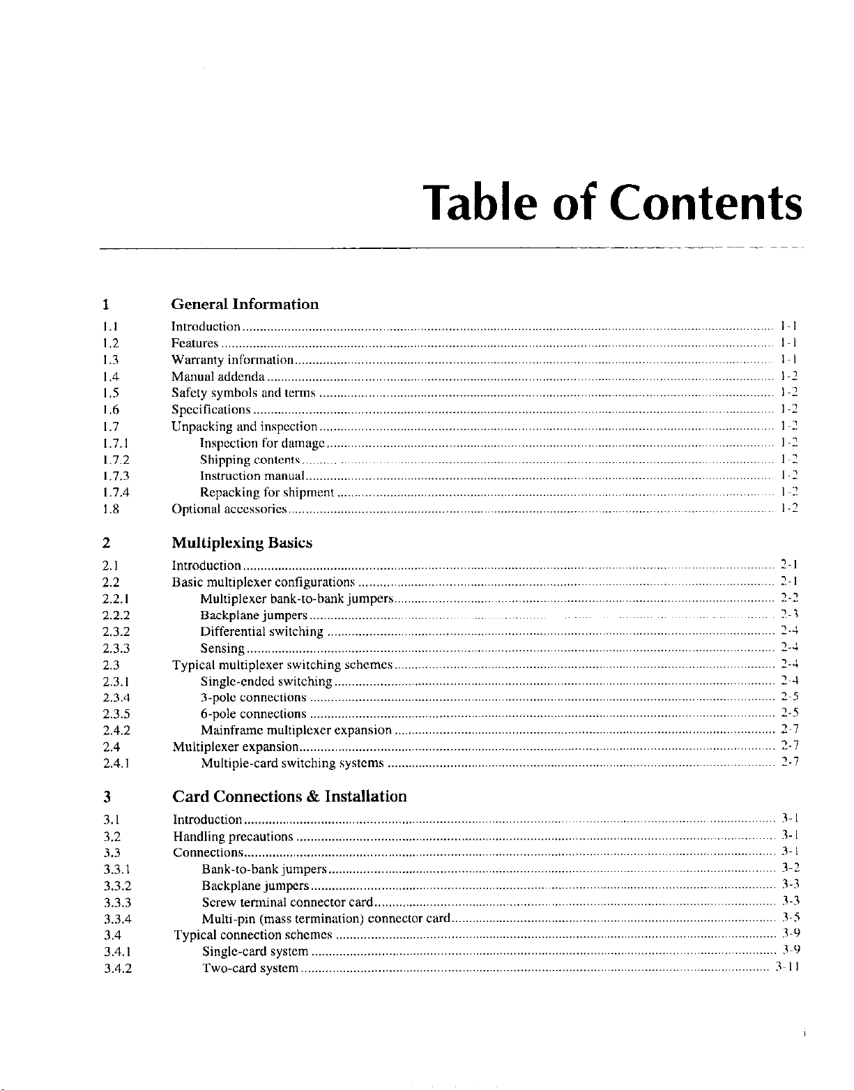
Table of Contents
1
1.1
1.2
1.3
I .4
1.5
1.6
1.7
1.7.1
1.7.2
1.7.3
1.7.4
1.8
General Information
Introduction
Features
WalTanty
Manual
Safety
Specifications..
Unpacking
Inspection for damage .................................................................................................................................
Shipping contents ........................................................................................................................................
Instruction manual
Repacking for shipment
Optional accessories
.........................................................................................................................................................
...............................................................................................................................................................
lnformatlo”.
addenda.. ................................................................................................................................................
symbols and terms ...................................................................................................................................
and inspcctio”.
.........................................................................................................................................
....................................................................................................................................................
.......................................................................................................................................
............................................................................................................................................
2 Multiplexing Basics
2.1
2.2
2.2.1
2.2.2
2.3.2
2.3.3
2.3
2.3. I
2.3.4
2.3.5
2.4.2
2.4
2.4. I
Introduction
Basic multtplexer configurations
Multiplexer bank-to-bank jumpers..
Backplane jumpers. .....................................................................................................................................
Differential switching .................................................................................................................................
Sensing ........................................................................................................................................................
Typical
Single-cndcd switching.. .............................................................................................................................
3.pole connections
h-pole connections ......................................................................................................................................
Mainframe multiplexer expansion
Multiplexer expansion..
Multiple-card swttchlng systems
.........................................................................................................................................................
multiplexer swtchlng schemes..
.......................................................................................................................................
..................................................................................................................................
..............................................................................................................................
?-I
........................................................................................................................
............................................................................................................
............................................................................................................
......................................................................................................................................
..............................................................................................................
................................................................................................................
2~ I
2-Z
2~3
2-J
2-J
2-4
2~4
2~5
2-S
2~1
2-7
Z-7
3
3.1
3.2
3.3
3.3.1
3.3.2
3.3.3
3.3.4
3.4
3.4.1
3.4.2
Card Connections & Installation
Introduction
Handling precautions
Connections
Bank-to-bank jumpers .................................................................................................................................
Backplane jumpers.. ....................................................................................................................................
Screw terminal connector card
Multi-pin (mass termination)
Typical connection schemes
Single-card system ......................................................................................................................................
Two-card system..
.........................................................................................................................................................
..........................................................................................................................................
.........................................................................................................................................................
....................................................................................................................
connector card..
...............................................................................................................................
.....................................................................................................................................
............................................................................................
3~ I
3 I
3~ I
3-X
3-3
3-3
3-5
3-9
3-5
3-I I
3.4.3
35.1
3.5
3.5.2
3.5.3
Two-mainframe system .............................................................................................................................
Ground screw .............................................................................................................................................
Model 7018 installation and removal
Multiplexer card installation. .....................................................................................................................
Multiplexer card removal
................................................................................................................ 3-14
.......................................................................................................................... 3-15
3- 12
3 I4
3- 15
4
4.1
4.2
4.2. I
4.2.2
4.3
4.3.1
4.3.2
4.3.3
4.3.4
4.4
4.4.1
4.4.2
4.4.3
4.5
4.5. I
4.5.2
4.5.3
4.5.4
4.5.5
4.5.6
4.5.1
5
5.1
5.2
5.3
5.3.1
5.3.2
5.3.3
5.3.4
5.3.5
5.3.6
5.3.1
5.3.8
5.4
5.5
5.5.1
5.5.2
5.5.3
5.5.4
5.6
5.6.1
56.2
5.6.3
Operation
Introduction
Operational constraints..
Maximum signal levels ................................................................................................................................
Channel hmdatlons .........................................................................................................................................
Mainframe control of multiplexer card
Channel assignments
Front panel control ......................................................................................................................................
IEEE-488 bus operation ..............................................................................................................................
Selecting 3-pale/6-pole operation ................................................................................................................
Multiplexer applications ......................................................................................................................................
Resistor testing ............................................................................................................................................
Transistor current gain testing .....................................................................................................................
Testing with matrix cards ............................................................................................................................
Measurement considerations ...............................................................................................................................
Path isolation ...............................................................................................................................................
Magnetic tields ..........................................................................................................................................
Radio frequency interference ....................................................................................................................
Ground loops .............................................................................................................................................
Keeping connectors clean.. ........................................................................................................................
AC frequency response.. ............................................................................................................................
Thermoelectric potentials ..........................................................................................................................
......................................................................................................................................................... 4-l
......................................................................................................................................
...............................................................................................................
...................................................................................................................................
4-l
4-l
4-l
4-l
4 -I
4-3
4-4
4-4
4-5
4-S
4-6
4-7
4-9
4-9
4 -10
4-10
4 -10
4-l 1
4-l 1
4-l I
Service Information
Introductio” .........................................................................................................................................................
Handling and cleaning precautions .....................................................................................................................
Performance verification .....................................................................................................................................
Environmental conditions.. ..........................................................................................................................
Recommended equipment ...........................................................................................................................
Multiplexer card connections ......................................................................................................................
Channel resistance tests.. .............................................................................................................................
Offset current tests.. ..................................................................................................................................... 5-3
Contact potential tests.. ................................................................................................................................
Bank and channel-to-channel isolation tests
Differential and common-mode ..................................................................................................................
Special handling of static-sensitive devices
Principles of operation .......................................................................................................................................
Block diagram ...........................................................................................................................................
ID data circuits ..........................................................................................................................................
Relay control .............................................................................................................................................
Relay power control ..................................................................................................................................
Troubleshooting.. ...............................................................................................................................................
Troubleshooting equipment.. .....................................................................................................................
Troubleshooting access .............................................................................................................................
Troubleshooting procedure.. ......................................................................................................................
...............................................................................................
......................................................................................................
5-l
5-l
5-l
5-2
5-2
5-2
5-3
5-5
5-6
5-8
5 -IO
5-l I
S-1 I
5 -I I
5-l I
5-12
5-12
5-l 2
5.12
S-12
ii

6.1
6.2
6.3
6.4
6.5
Replaceable Parts
Introduction
Parts lists
Ordering information ..........................................................................................................................................
Factory service
Component layouts and schemetic ......................................................................................................................
.........................................................................................................................................................
.............................................................................................................................................................
h- I
6-I
b- I
....................................................................................................................................................
h-l
6 -I
iii

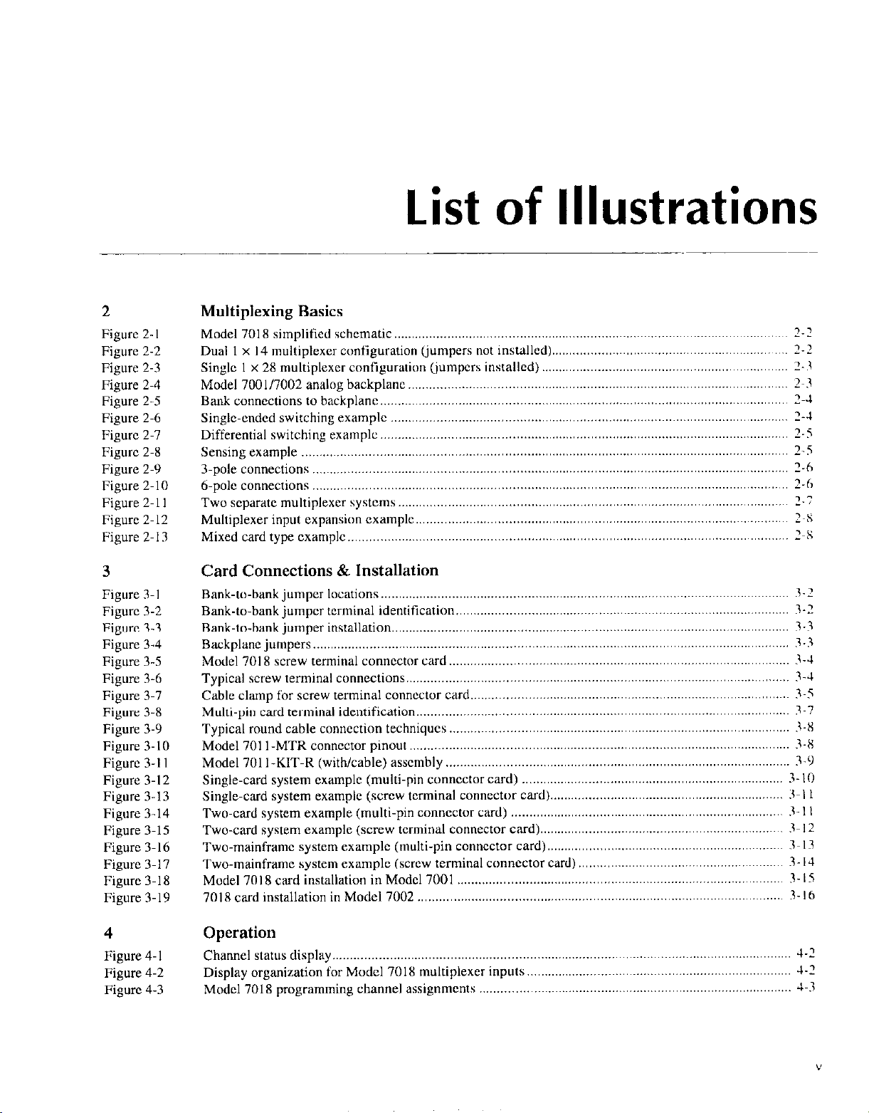
2 Multiplexing Basics
Figure 2. I
Figure 2-2
Figure 2-3
Figure 2-4
Figure 2-5
Figure 2-6
Figure 2-7
Figure 2-X
Figure 2-9
Figure 2-l 0
Figure 2. I I
Figure 2. I2
Figure 2. I3
Model 7018 simplified schematic..
Dual 1 x 14 multiplexer configuration (jumpers not installed)
Single I x 28 multiplexer configuration (jumpers installed)
Model 7001/7002 analog backplane ...........................................................................................................
Bank connections to backplane ,.,..................................., ............................................................................
Single-ended switching example
Differential switching example..
Sensing example
3.pole connections
6.~01~ connections
Two separate multiplexer systems..
Multiplexer input cxpension example
Mixed card type cxamplc ...... ..................................
........................................................................................................................................ 7-5
............ . .....
............
List
.............................................................................................................
.._
............
......... .... .... .............. .......... .. .... ... ....
................................................................................................................. 2-h
.._
................................................................................................................ 1-h
. .
.._
.....
.....................................................................................
...............................................................................................
.........
of
.............................................................................................. 2~8
..............................................................................
Illustrations
................................................................... 2-2
...................................................................... 2-3
.. ........
............................
2-2
2~3
2-J
........... 2-J
1-5
............
2-7
2~8
3
Figure 3-I
Figure 3-2
Figure 3-3
Figure 3-4
Figure 3-5
Figure 3-6
Figure 3-7
Figure 3-X
Figure 3-9
Figure 3-10
Figure 3-l I
Figure 3-12
Figure 3-13
Figure 3-14
Figure 3-15
Figurc 3-16
Figure 3-17
Figure 3-18
Figure 3-19
4
Figure 4-l
Figure 4-2
Figure 4-3
Card Connections & Installation
Bank-to-bank jumper locations ..,.......,.._ .....................................................................................................
Bank-to-bank jumpcr terminal identtficatton ,......................................., .....................................................
Bank-to-bank jumper installation
Backplane jumpers ._...............,,..,., ..............................................................................................................
Model 7018 screw terminal connector card..
Typical screw terminal connections..
Cable clamp for screw terminal connector card..
Multi-pin card terminal identif~catlon.. ... .. .... .. ... ......... ... .......
Typical round cable connection techniques ,.....,.,...,.,...._ ............................................................................
Model 701 1 -MTR connector pinout
Model 701 I-KIT-R (with/cable) assembly
Single-card system example (multi-pin connector card) _...,
Single-card system example (screw terminal connector card).
Two-cud system example (multi-pin connector card) .._.._
Two-card system example (screw terminal connector card)
Two-mainframe system example (multi-pin connector card)
Two-mainframe system example (screw terminal connector card)
Model 7018 card installation in Model 7001
7018 card installation in Model 7002 ..... ...................................
..
........ ....
.._............................................. ................................................... 3-i
........................................................................ 3-J
.._.......,
...........
.......................................................................................................... 3-J
.. ..... ........... ......... .....
......................................................................................................
....
......................................
.....................................................................
................................................................. 3-l I
....................................................................... 3-l I
..................................................................... 3- I2
..........................................................
.._
......
..........................................................
..... .. .. ......... ........
.........................................................
..............................................
......................................................
.......................................................... 3-9
...................................................
3-1
3-Z
3-3
3~5
3~7
3-X
i-X
3 -IO
3~ I3
3- IJ
3-15
3 16
Operation
Channel status display .._..............,.,,...........................,.,....., .......................................................................
Display organization for Model 7018 multiplexer inputs..
Model 7018 programming channel assignments
.._..,,, ..........................................................................
....
..............................................................
... ....
J-2
J-2
J-3

Figure 4-4
Figure 4-5
Figure 4-6
Figure 4-7
Figure 4-8
Figure 4-9
Figure 4-10
Figure 4-l I
Figure 4. I2
Four-wire resistance
testing.. .......................................................................................................................
Low resistance testing .................................................................................................................................
Configuration for current gain test ..............................................................................................................
cards together .....................................................................................
Connecting multiplexer and
Path isolation resistance
Voltage attenuation
by path isolation resistance
Power line ground loops
matrix
..............................................................................................................................
.......................................................................................
............................................................................................................................
Eliminating ground loops ..........................................................................................................................
Thermoelectric
generation.. .......................................................................................................................
4-6
4.7
4.8
4-9
4-9
4.10
4-I 0
4-l I
4-l
I
5
Figure 5-l
Figure 5-2
Figure 5-3
Figure 5-4
Figure 5-5
Figure 5-6
Figure 5-7
Figure 5-X
Figure 5-9
Figure 5-10
Service Information
Path resistance
Offset current
test connections.. .................................................................................................................
test connections ....................................................................................................................
Contact potential test connections.. .............................................................................................................
Bank isolation
Channel-to-channel
Differential isolation test connections..
Common-mode
Model 7018 block diagram..
Start and stop sequences
Transmit and acknowledge sequence..
test connections ...................................................................................................................
isolation test connections
..
lsolatmn test connections..
............................................................................................
.....................................................................................................
...............................................................................................
......................................................................................................................
............................................................................................................................
......................................................................................................
5-3
5-4
5.5
5-7
5-7
5.10
IO
5
5 -I
5 -1 I
5 -I I
I
vi
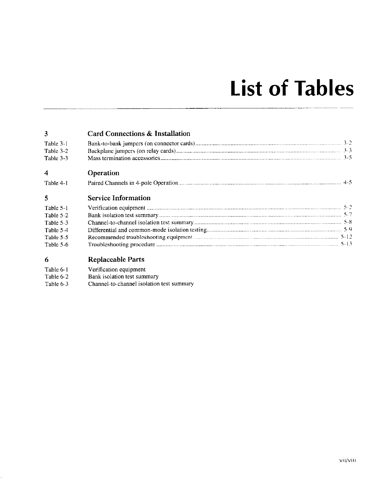
List
of Tables
3
Table 3. I
Table 3-2
Table 3-3
4
Table 4-l
5
Table 5-l
Table 5-2
Table 5-3
Table 5-4
Table 5-5
Table 5-6
Card Connections & Installation
Bank-to-bank jumpers (on connector cuds) ~..~ 3~2
Backplane jumpcrs (on r&y cards) ~.~ 3~3
Mass termmatton accessories . 3-5
Operation
Paired Channels in 4.pole Operation .,.........................,,,,....,.,..,,....,,.......................................................... 4-S
Service Information
Verification equipment .... ~.,
Bank isolation test summary ..,..,.....,............................,...................................................................~.......... S-7
Channel-to-channel isolation test summary 5-X
Differential and common-mode isolation testing ~.~...~~.~
Recommended troubleshooting equipment 5. I2
Troubleshooting procedure 5- I3
6 Replaceable Parts
Table 6-I Verification equipment
Table 6-2
Table 6-3
Bank isolation test summary
Channel-to-channel isolation test summa~
5~2
SL)

General Information
1.1
This section contains general information about the Model
7018 28.Channel 3.Pole Multiplexer Card.
There are two basic versions of this multiplcxcr card; the
Model 7018-S and the Model 7018-C. The Model 701X-S asscmbly consists of a screw terminal connector card and a relay card. External test circuits arc wired directly to the screw
terminals of the connector card. Also available from Keithley is the Model 7018.ST. This accessory is an extra screw
terminal connector card. With an extra connector card, you
can wire a second test system without disturbing the wiring
configuration of the first test system.
The Model 7018-C assembly consists of a multi-pin (mass
termination) connector card and the relay card. External test
circuit connections to the multiplexer are made via the 96.
pin male DIN connector on the connector card. Keithley offers a variety of optional accessories that can be used to make
connections to the connector card (see paragraph I .a).
The rat of Section I is arranged in the following manner:
1.2 Features
1.3 Warranty information
1.4 Manual addenda
1.5 Safety symbols and terms
1.6 Specifications
introduction
I.8 Optional accessories
1.2 Features
The Model 7018 is a three-pole.
card. Some of the key features include:
* Low contxt potential and offset current for Iminimal cf-
fats on low-Icvcl signals.
. The connector board detaches fronl the rulq board
allowing easy access to the screw terminals (.Modcl
7018-S) and jumpers.
* Easy jumper configuration of one or two multiplcxcr
banks(I x28or2x 14).
* Backplane jumpers. Cutting jumpers disconnects muIt&
plcxcr hank outputs from the Model 700117002 imalog
backplane.
.
l-pole or 6-p& operation.
2X-cbanncl multiplc*cr
1.3 Warranty information
Warranty information is located on the inside front cover ot
this instruction manual. Should your Model 7018 rcquirc
warranty scrvicc. contiict the Keithlcy rcpresentatiw or
authorized repair facility in your area for further informotion. When returning the multiplexer card for repair. be
sure to till out and include the service form at the back of this
manual in order to provide the repair facility with the
necessary information.
1.7 Unpacking and inspection
l-1
1.4 Manual addenda
Any improvements or changes concerning the multiplexer
card or manual will be explained in an addendum included
with the card. Addenda are provided in a page replacement
format. Simply replace the obsolete pages with the new
pa&X.
2. When not installed in a Model 7001/7002 mainframe,
keep the card in the anti-static bag, and store it in the original packing carton.
After removing the card from its anti-static bag, inspect it for
any obvious signs of physical damage. Report any such damage to the shipping agent immediately.
1.5
The following symbols and terms may be found on an instro-
ment or used in this manual.
The L!?!, symbol on an instrument indicates that the user
should refer to the operating instructions located in the instruction manual.
The
more may be present on the terminal(s). USC standard safety
precautions to avoid personal contact with these voltages.
The WARNING heading used in this manual explains dangers that might result in personal injury or death. Always
read the associated information very carcfully before performing the indicated procedure.
The CAUTION heading used in this manual explains hazards that could damage the multiplexer card. Such damage
may invalidate the warranty.
Safety symbols and terms
f
symbol on an instrument shows that IOOOV or
1.7.2 Shipping contents
The following items are included with every Model 7018 ordcr:
- Model 7018 2%channel 3-pole Multiplexer Card
- Model 7018 Instruction Manual
- Additional accessories as ordered
1.7.3 instruction manual
The Model 7018 Instruction Manual is three-hole drilled so
that it can be added to the three-ring bindcr of the Model
700117002 instruction Manual. After removing the plastic
wrapping, place the manual in the binder following the mainframe instruction manual. Note that a manual identification
tab is included and should precede the multiplexer card in-
stnrction manual.
If an additional instruction manual is required, order the
manual package, Keithlcy part number 701X-901-00. The
manual package includes an instruction manual and any per-
tinent addenda.
1.6 Specifications
Model 7018 specifications are found at the front of this man-
ual. These specifications are exclusive of the switching
mainframe specifications.
1.7 Unpacking and inspection
1.7.1 inspection for damage
The Model 7018 is packaged in are-sealable, anti-static bag
to protect it from damage due to static discharge and from
contamination that could degrade its performance. Before rcmoving the card from the bag, observe the following precautions on handling.
Handling Precautions:
I. Always grasp the card by the side edges and shields. Do
not touch the board surfaces or components.
1-2
1.7.4 Repacking for shipment
Should it become necessary to return the Model 7018 for repair, carefully pack the unit in its original packing carton or
the equivalent, and include the following information:
- Advise as to the warranty status of the multiplexer card.
. Write ATTENTION REPAIR DEPARTMENT on the
shipping label.
* Fill out and include the service form located at the back
of this manual.
1.8 Optional accessories
The following accessories are available for use with the
Model 7018:

Model 701%ST - This screw terminal connector card is
identical to the one provided with the Model 7018-S assembly. An extra screw terminal connector card allows you to
wire a second test system without disturbing the wiring conliguration of the first connector card.
Model 701 l-MTC-Z-This 2.mctcr round cable assembly
is terminated with a 96.pin female DIN connector on each
end. It will mate directly to lbc connector on the Model
701X-C and to a standard Y6-pin male DIN bulklaid com~cctar (see Model 701 I-MTR).
Model 7011-KIT-R-This connection kit includes a 96.pin
fcmalc DIN connector that will mate directly to the conncctar on the Model 7018-C or to a standard Yh-pin male DIN
bulkhead connector (see Model 701 I -MTR). This connector
uses solder cups for connections to external circuitry. It includes an adaptcr for a round cable and the housing.
Model 701 I-MTR - This Y&pin malt DIN bulkhead con
ncctor uses solder cups for connections 10 e.xtemal circuitr).
It wilt mate to the Model 701 I -KIT-K connector. and !vI~niel
701 t -MTC-2 cable assembly.
2
Multiplexing Basics
2.1 Introduction
This section covers the basics for multiplex switching and is
arranged as follows:
2.2 Basic multiplex configurations: Covers the basic
multiplex configurations: dual I x 14 configuration
and single I x 28 configuration. The backplane jumpers are also covered here.
2.3 Typical multiplexer switching schemes: Explains
some of the basic ways a multiplexer can be used for
switching. Covers sin&cndcd switching, diffcrcntiat
(floating) switching, sensing, and 3-pale/6-pole operation.
2.4 System expansion: Discusser the various configor;tlions that arc possible by using multiple cwds.
2.2 Basic multiplexer configutations
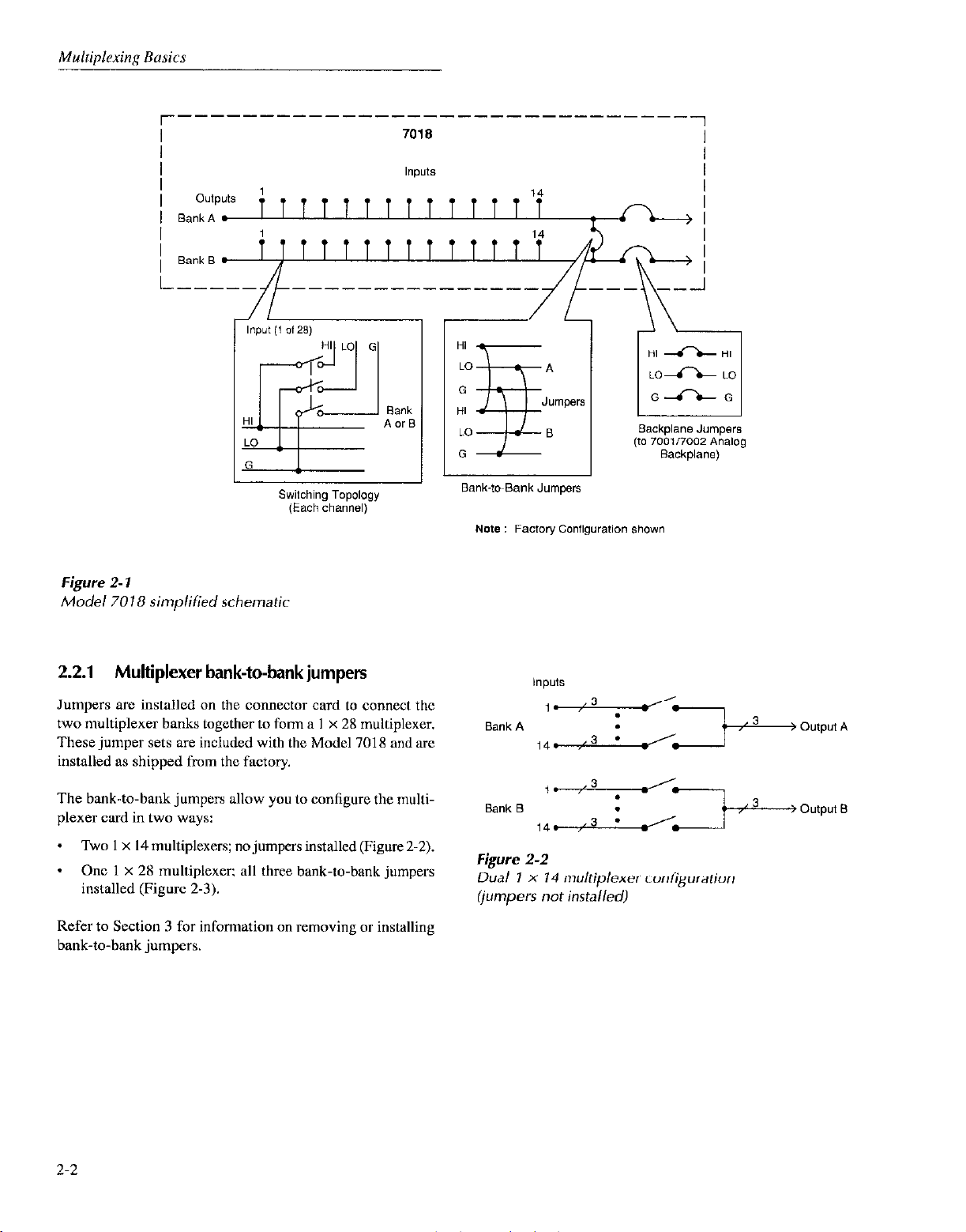
A simplified schematic of the Model 70 t 8 multiplexer card
is shown in Figure 2. I. It is organized ns two I x t 4 multiplexer banks. Each bank has 14 inputs and one output.
Three-potc switching is provided for each mult~plcxcr input.
with HI. LO, and guard switcbcd The banks can bc junlpercd together to expand muttiplcxcr inputs, and beckplanc
jumpers provide bank connections to other card(s) installed
in a Model 7001/7002 mainframe.
2-t
r-----
-----_-______-------------
7018
1
Note : Factory Config”ration shown
Figure 2- 1
Model 7018 simplified schematic
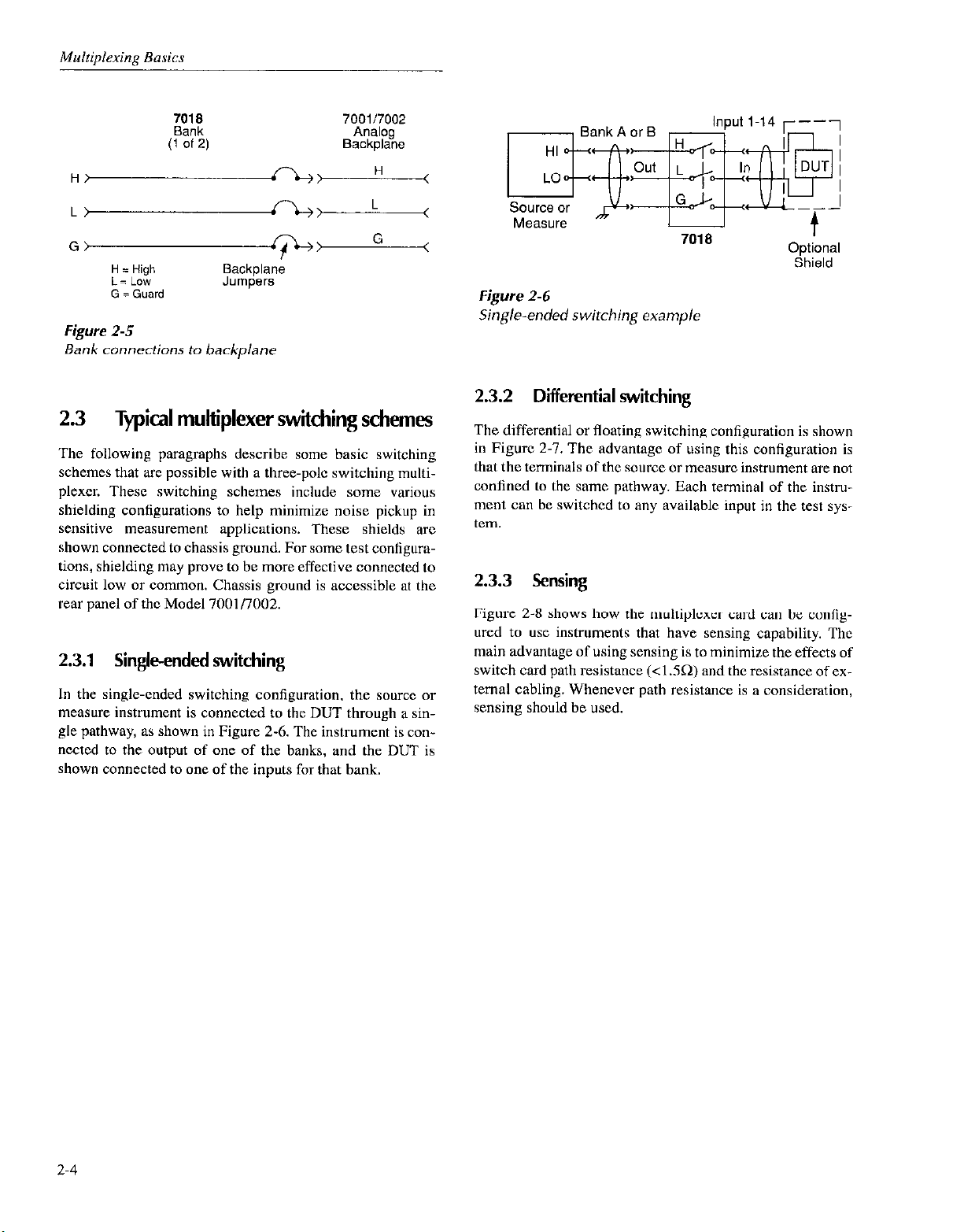
2.2.1 Multiplexer bank-to-bank jumpers
Jumpers arc installed on the connector card to connect the
two multiplexer banks together to form a I x 28 multiplexer.
These jumper sets are included with the Model 7018 and are
installed as shipped from the factory.
The bank-to-bank jumpers allow you to configure the multi-
plexer card in two ways:
* Two 1 x I4 multiplexers; no jumpers installed (Figure 2-2).
* One 1 x 2X multiplexer; all three bank-to-bank jumpers
installed (Figure 2-3).
Refer to Section 3 for information on removing or installing
bank-to-bank jumpers.
Figure 2-2
Dual 1 X 14 multiplexer configuration
(jumpers not installed)
2-2

Figure 2-3
Single1 x28 multiplexer configuration (jumpers installed)
2.2.2 Backplane jumpers
NOTE
When the backplane jumpers nrc installed.
connecting the banks together on one card
will automatically connect the banks of
cards in other slots to~cther.
Figure 2-5 shows how each bank of the Model 701X i> cons
ncctcd to the backpbmc. The Model 70 IX is shipped fro111 the
factory with the backplxx jumpers installed.
&moving (cutting) the beckphuw .jumpws isrrlatcs the card
from the beckplanc. and subsequently. any card installed in
the other slot. For information on rcmoviny the jumpcr~. rcfcr to Section 3.
There arc six backplane jumpers located on the relay card
(three for each bank). With the jumpers instelled, the banks
of the multiplexer card are connected to the analog backplane of the Model 7OOl/7002, allowing expansion with other 7001/7002 card(s) installed in the mainframe. With the
jumpers removed (cut), the multiplexer card is isolated from
other card(s) installed in the mainframe.
The three-pole analog backplane of the Model 700117002
mainframe is shown in Figure 2-4. Through this analog
backplane, the banks of a Model 7018 multiplexer card, in-
stalled in one slot, can be connected to the banks (or rows) of
n compatible card installed in another slot of the mainframe.
Model 7001/7002
Analog
Backplane
Row 2 or Bank B
r----
l
Card 1
l r----
I I
&------!‘L
G\!-?G
I
I I
H)I
NOTE
The Model 7(101I7002 dots not provide itn
analog backplane for the non-701X scrics
cards. As a result, any of these c;irds installed in one slot in the nwinfrwnc is clectrically isoletcd from any card instidlcd io
another slot. The only way to connect il
Model 701X to one of thcsc cards is to wire
them togcthcr cxtemelly,
Card 2
I
KH
I
I
I
L------------.
Figure 2-4
Model 7001/7002 analog backplane
L\/t,
Gi-10
H = High
L= LOW
G = Guard
L----- -------
ROW = Matrix Card (7012,
Bank = MUX Card 17018,
7018
Bank
(1 Of 2)
700117002
Analog
Backplane
I
, BankAorS I
Input l-14 r---)
,- I
H‘A., H
L‘A L
G>
H = High
i= LOW
G = Guard
Figure 2-5
Bank connections to backplane
2.3
The following paragraphs describe some basic switching
schemes that are possible with a three-pole switching multiplexer. These switching schemes include some various
shielding configurations to help minimize noise pickup in
sensitive measurement applications. These shields are
shown connected to chassis ground. For some test configurations, shielding may prow! to be more effective connected to
circuit low or common. Chassis ground is accessible at the
rear panel of the Model 7001/7002.
Typical multiplexer switching schemes
Jumpers
9::
Backplane
G
<
<
<
2.3.1 Single-ended switching
In the single-ended switching configuration, the source or
measure instrument is connected to the DUT through a single pathway, as shown in Figure 2-6. The instrument is connected to the output of one of the banks, and the DUT is
shown connected to one of the inputs for that bank.
Measure or
Figure2-6
Sing/e-ended switching example
t
Optional
Shield
2.3.2 Differential switching
The differential or floating switching configuration is shown
in Figure 2-l. The advantage of using this configuration is
that the terminals of the source or measure instrument are not
confined to the same pathway. Each terminal of the instrument can be switched to any available input in the test system.
2.3.3 Sensing
Figure 2-8 shows how the multiplexer card can be configured to use instruments that have sensing capability. The
main advantage of using sensing is to minimize the effects of
switch card path resistance (<I .SQ) and the resistance of ex-
ternal cabling. Whenever path resistance is a consideration,
sensing should be used.
2-4

Figure 2-7
Differential switching example
3”“ICtl “I -
Sense HI
Figure 2-8
Sensing example
I-
701
Input I-14
a
7018
2.3.4 3-pole connections
Figure 2-9 shows typical 3-p& connections using a single
channel to switch both source and measure instruments to
the DUT. In this example, source HI and measure HI arc
routed separately to the DUT, while the LO terminals xc
connected together externally.
2.3.5
6-pole connections
The Model 7018 can also be used for h-pole switching for
testing more complex DUTs. Figure 2. IO shows typical Opole connections. In order to use h-pole switching. Ihc tikc-
numbcrcd channels of Banks A and I3 must bc paired togcther (Bank A, Input I with Bank B. Input I, etc.,. See ,>a~graph 4.3.4 f& informalion on sclting up the switching
mainframe for h-potc operation.
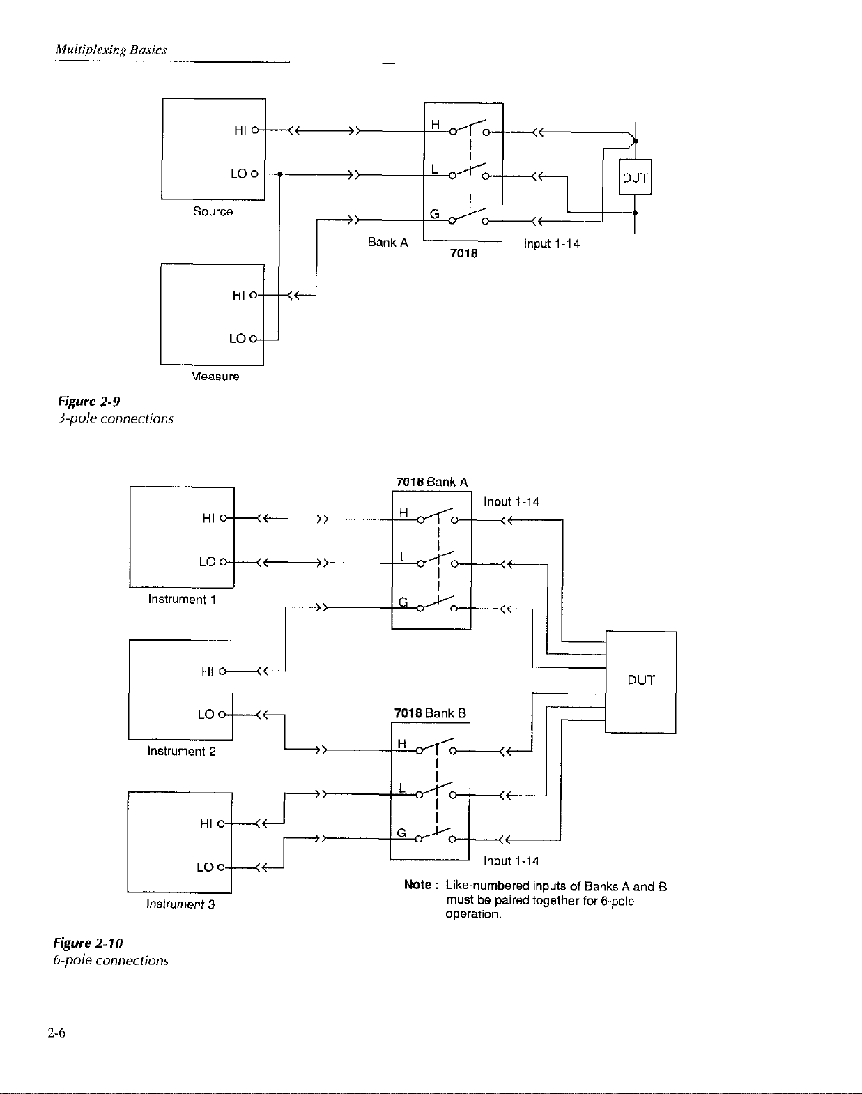
Figure 2-9
3-p& connections
HI 0
LO
ci
HI
LO
--
t---j-
Lit )
Instrument 1
r
Instrument 3
1 DUT
Note : Like-numbered inputs of Banks A and Et
must be paired together for &pole
operation.
Figure 2- 10
6.pole
2-6
connections
2.4 Multiplexer expansion
With the USC of additional switching cards and mainframes.
larger systems can be configured. Each Model 7001 Switch
System mainframe will accommodate up to two cards. and
each Model 7002 Switch System can hold up to IO cards.
2.4.1 Multiple-card switching systems
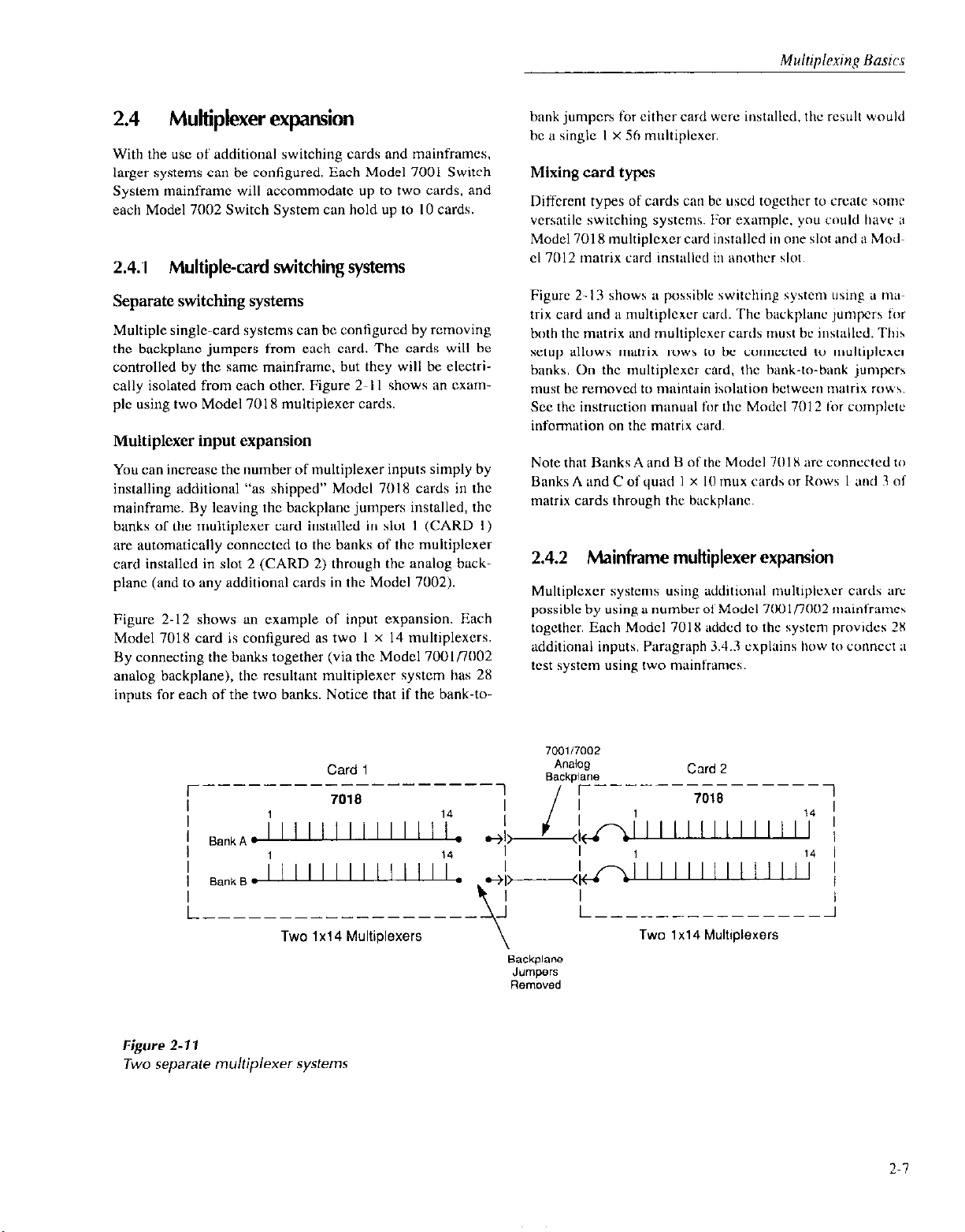
hank jumpcrs for either card were installed. the rewh would
be a single I x 5h muhiplexcr.
Mixing card types
Different types of cards cw bc used togcthcr to create some
vcrsatilc switching systems. For cxemplc. you could have it
Model 7018 multiplexer card instellcd in one slot and ii Modcl 7012 matrix card installed ill imothcr slot.
Separate switching systems
Multiple single-card systems can be configured by removing
the backplane jumpers from each card. The cards will be
controlled by the sane mainframe, but they will be clcctrially isolated from each other. Figure 2-l I shows an exemplc using two Model 7018 multiplexer cards.
Multiplexer input expansion
You can incrcasc the number of multiplexer inputs simply by
installing additional “as shipped” Model 7018 cards in the
mainframe. By leaving the backplane jumpers installed, the
banks of the multiplexer card installed in slot I (CARD I)
arc automaticttlly conncctcd to the banks of the multiplexer
card installed in slot 2 (CARD 2) through the analog backplane (and to any additional cards in the Model 7002).
Figure 2-12 shows an example of input expansion. Each
Model 7018 card is configured as two I x I4 multiplcxers.
By connecting the banks together (via the Model 7OOlflOO2
analog backplane), the resultant multiplexer system has 28
inputs for each of the two banks. Notice that if the bank-to-
Card 1
7018
r----
______---------
Figure 2-13 shows a possible switching system using a nw
trix card and a muhiplcxcr card. The bxkphmc jumpus for
both the matrix and multiplcxcr cards must bc installcd. Thih
setup allows mntrix rows to be conncctcd to multiplexer
banks. On the muhiplcxcr card. the bank-to-bank jumpers
must be removed to maintain isolation hctwccn matrix IOU\.
See the instruction Manuel fur the Model 7012 ior complctc
information on the matrix card.
Note that Banks A and B of the Model 70 IX arc connected tiz
Banks A and C of quad 1 x IO mux cards or Rows I and 3 of
matrix cards through the backplane.
2.4.2
Muhiplcxcr systems using udditional muhiplexcr cards arc
possible by using a number of Model Xi) l/7002 n~~inframc~
together. Each Model 701X added to the system provides 2X
additional inputs. Paragraph 3.4.3 cxphlins hwv tu connc~t a
wst system using two mainframes.
1
I
Mainframe multiplexer
700117002
A”CliOg
Backpiane
r----
I I
_----------
Card 2
7018
expansion
1
I
Figure 2-11
Two
separate multiplexer systems
Two 1x14 Multiplexers Two 1 x14 Multiplexers
 Loading...