

Tektronix 503 Instruction Manual
INSTRUCTION MANUAL
MODELS 503, 503C
MILLIOHMMETERS
0 COPYRIGHT 1976, KEITHLEY INSTRUMENTS, INC.
PRINTED MAY 1977, CLEVELAND, OHIO, U.S.A.
MODEL 503
CONTENTS
CONTENTS
Section
Page
SpECIpIC*TIONS ---------------------------------------------------- iv
GENERAI, DESCRIPTION ________-___________----------------------- 1
1.
OpE&Q-ION ----------------------------------------------------- 2
2.
CIRCUIT DESCRIPTION ------------------------------------------- 12
3.
SERVICING -_-_------------------------------------------------- 18
4.
REpL)&E&LE pm',-- ____-___________________________________-----
5.
SCHE&yJIC --------------------------------------------------------- 31
24
ii
0874
MODEL 503
Pip;.
ILLUSTRATIONS
No. Title
1 Front Panel. ---------------__----------------------------
ILLUSTRATIONS
Page
1
2 Pour Terminal Measurement. -------------------------------3 Model 503 Controls. -_--__________-_-_-___________________
4 lbo-terminal Connection. ------_-_-_________-_____________
5 Modification for &ground Chassis. -----------------------6 Series Resistance Measurements. ----------_---______------
7
a
9 Super Regulated 12 Volt Supply Schematic Diagram. ---------
10 Test Current Generator Schematic Diagram. ----------------11 AC Amplifier Schematic Diagram. _--_________-__--_________
12 Synchronous Demodulator Meter - Output. _-______---_-______
13
14
15 Location of Printed Circuit Board Components. ------------
16 Location of Range Switch Components. ---------------------
Exploded View for Rack Mounting. ------------------------Power Supply Schematic Diagram.
Waveform of Synchronous Demodulator. ----------------------
Model 503 Internal Components Locations (Top Removed). ----
------------_---__________
2
5
6
7
9
11
12
13
14
16
17
19
21
22
23
0874
c
iii
SPECIFICATIONS
MODEL 503
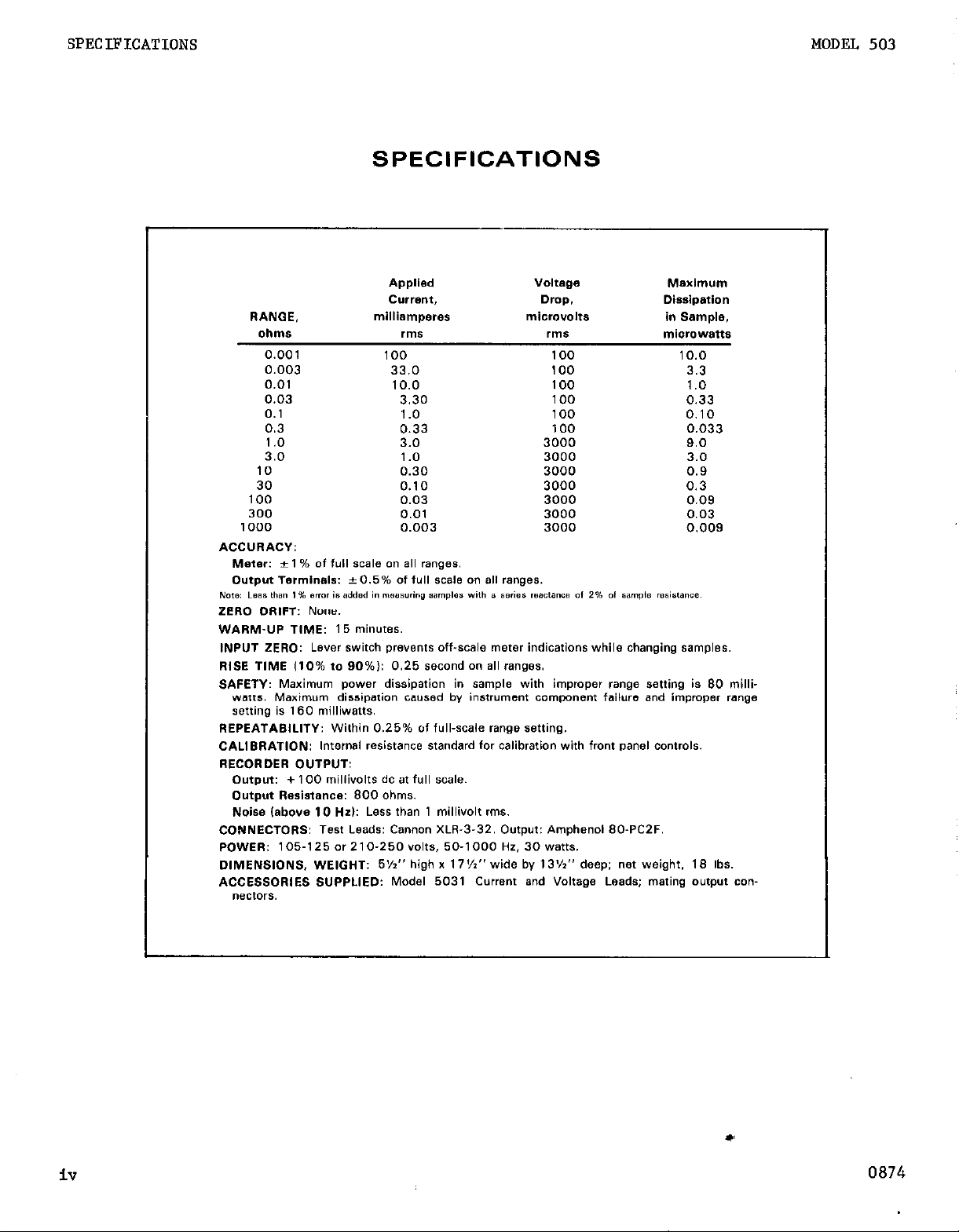
SPECIFICATIONS
Applied
C”Wl?“t,
RANGE,
oIlIll* rnls rms
0.001 100 100 10.0
0.003 33.0 100 3.3
0.01 10.0 100 1.0
0.03 3.30 100 0.33
0.1 1.0 100 0.10
0.3 0.33 100 0.033
1.0 3.0 3000 9.0
3.0 1 .o 3000 3.0
10 0.30 3000 0.9
30 0.10 3000 0.3
100 0.03 3000 0.09
300 0.01 3000 0.03
1000 0.003 3000 0.009
ACCURACY:
Meter: * 1 % of ‘“,I SCSI0 an a,, ranges.
Output Te,lni”al*: +0.5% Of ‘“II SC& an a,, ranges.
Nom Less U’S” 1% Brmr ts added I” measuring 9amp1e. with B series resctanca Of 2% Of “ample m.i.l.“E..
ZERO DRIFT: None.
WARM-UP TIME: 15 minutes.
INPUT ZERO: Lever ~wifch prevenf~ off-scale meter indications while changing samples.
Rl8E TlME 110% to 90%): 0.25 second an a11 wmges.
SAFETY: Maximum power dissipation in sample with improper range setting is 80 milli-
wets. Maximum dissipation cawed by instrument component failure and improper range
sating is 160 milliwatts.
REPEATABILITY: Within 0.25% of full-scale range setting.
CALIBRATION: Internal redstance standard for calibration with front panel controls.
RECORDER D”TPwr
Output: + 100 millivolts dc at full scale.
Output Resistance: 800 ohms.
Noise (above IO Hzl: Less than 1 millivolt rms.
CONNECTORS: Test Leads: Cannon XLR-3-32. Output: Amphenol 80.PC2F.
POWER: 105-I 25 or 2 1 O-250 YOltS, 50-1000 HZ. 30 watts.
DIMENSIONS, WEIGHT: 5%” high x 17%” wide by 13%” deep; net weight. 18 Ibs.
ACCE88DRlES 8”PPUED: Model 5031 Current and Voltage Leads; mating o”f,,“t con-
“eCtOr*.
milliamperes
Voltage
Drop.
microvolts in Sample.
ME2tdll”~
Dissipation
miorowatts
iv
0874
MODEL 503
GENERAL DESCRIPTION
SECTION 1.
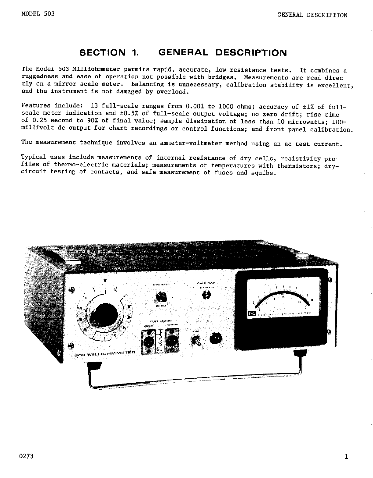
The Model 503 Milliohnuwter permits rapid, accurate, low resistance tests.
ruggedness and ease of operation not possible with bridges.
tly on a mirror scale meter.
and the instrument is not damaged by overload.
Features include: 13 full-scale ranges from 0.001 to 1000 ohms; accuracy of +l% of full-
scale meter indication and ?0.5% of full-scale output voltage; no zero drift; rise time
of 0.25 second to 90% of final value;
millivolt dc output for chart recordings or control functions;
The measurement technique involves an ammeter-voltmeter method using an ac test current.
Typical uses include measurements of internal resistance of dry cells, resistivity pro-
files of thermo-electric materials;
circuit testing of contacts,
Balancing is unnecessary,
and safe measurement of fuses and squibs.
GENERAL DESCRIPTION
It combines a
Measurements are read direc-
calibration stability is excellent,
sample dissipation of less than 10 microwatts; lOO-
and front panel calibration.
measurements of temperatures with thermistors; dry-
0273
OPERATION
MODEL 503
SECTION 2.
2-1.APPLICAl'IONS: The Keithley Model 503 Milliohmmeter is especially useful
for accurate measurement of low value resistors; resistances of lead wires,
terminal connector contacts and welds; resistance change in conductors due
to temperature and humidity effects;
conductors; resistivity of semiconductors, contact resistance of vibrators,
relays and choppers and internal resistance of dry cells. Also for resistivity profiles of thermoelectric materials end safe measurement of squibs and
fuses.
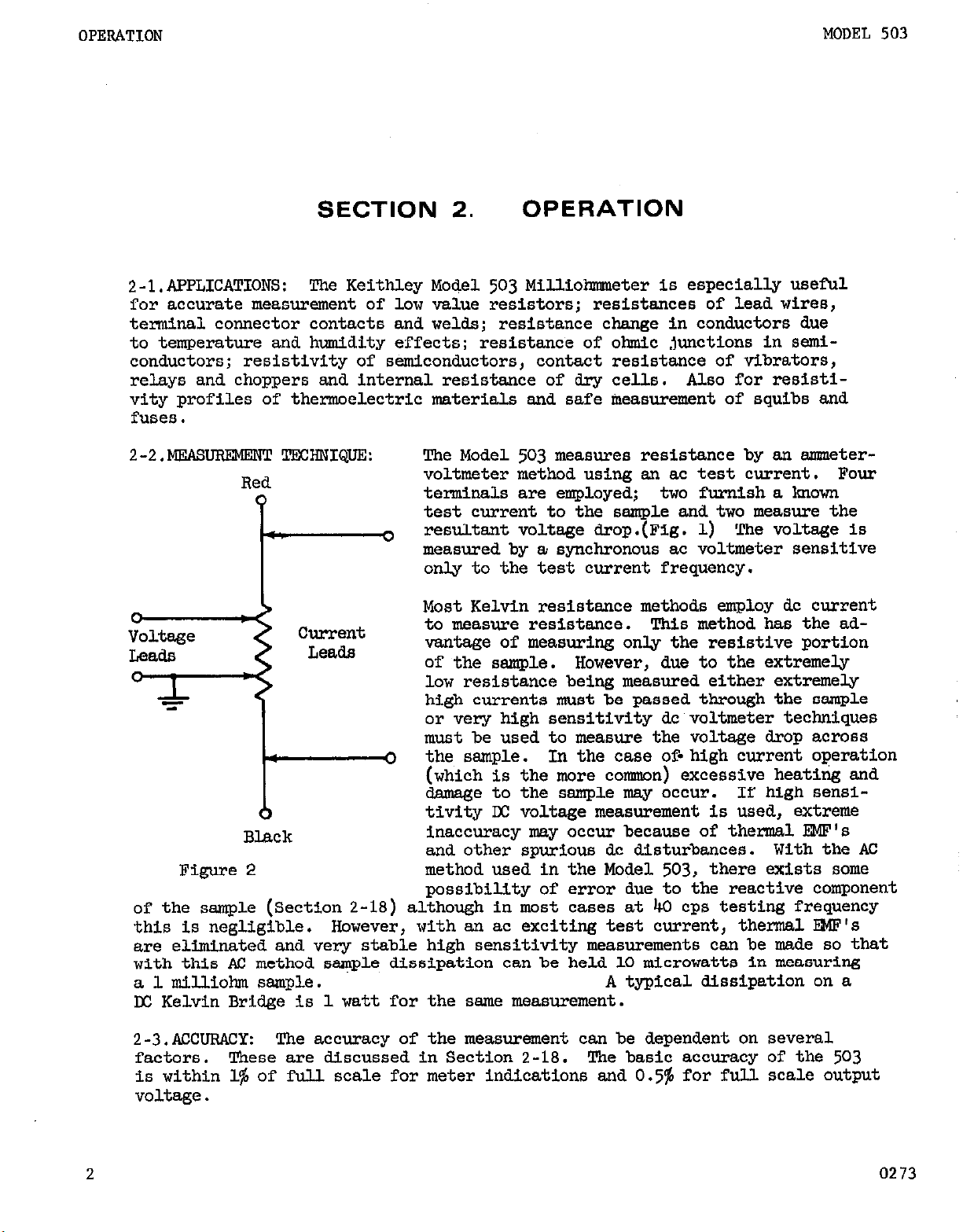
2-2.MEAsuRBMERT TECHNIQUE:
Red
0
w.
Current
Leads
*
0
Black
Figure2
of the sample (Section 2-18) although in most cases at 40 cps testing frequency
this is negligible.
are eliminated and very stable high sensititity measurements can be made so that
with this AC method sample dissipation can be held 10 microwatts in measuring
a 1 milliobm sample. A typical dissipation on a
D(: Kelvin Bridge is 1 watt for the ssme measurement.
However, with an ac exciting test current, thermal E?@'s
!Che Model 503 measures resistance by an metervoltmeter method using an ac test current. Four
terminals are employed; two furnish a known
test current to the sample and two measure the
resultant voltage drop.(Fig. 1) !Che voltage is
3
measured by a synchronous ac voltmeter sensitive
only to the test current frequency.
Most Kelvin resistance methods employ dc current
to measure resistance. !l%is method has the advantage of measuring only the resistive portion
of the sample.
low resistance being measured either extremely
high currents must be passed through the sample
or very high sensitivity dc voltmeter techniques
must be used to measure the voltage drop across
the sample.
0
(which is the more cosnnon) excessive heating and
damage to the sample msy occur. If high sensitivity LX voltage measurement is used, extreme
inaccuracy may occur because of thermal EKF's
and other spurious dc disturbances. With the AC
method used in the Model 503, there exists some
possibility of error due,to the reactive component
OPERATION
resistance of ohmic junctions in semi-
However, due to the extremely
In the case of-high current operation
2
2-3.ACcuRACY:
factors. These are discussed in Section 2-18.
is within 1% of full scale for meter indications and 0.5% for full scale output
voltage.
The accuracy of the measurement can be dependent on several
The basic accuracy of the 503
0273
MODEL 503
2-4.RRPEATABILSl'Y: Raving once established a reading for a particular sample
measurement, it is possible to repeat within 0.25% of the full scale range setting. This assumes the connections to the sample remain fixed.
OPERATION
2-5.CALIRRATION: The
resistance standards to check its accuracy.
503
is self calibrating and thus reduces the need for
It is possible to verify the cali-
bration with or without the sample attached to the test leads. (See Sect. 2-14)
2-6.VOVIMETER SPECIFICATIONS:
Since the
503
uses a synchronous demodulator,
the voltmeter is sensitive only to signals of the test current frequency.
The sensitivity and input impedance are listed in Table 2.
TABLE2
Rms Input for Full
Remges
Milliohm
Ohm
Scale Deflection
100 uv
3000
uv
2 in
200
ohms
1 x 10⁶ ohms
2-7.TRST CURRENT CRARACTRRISTICS: The testcurrent is a square wave derived
from the transistor inverter.
justed as discussed in Section 3-2.
The frequency is about 40 cps, and can be ad-
This may be desirable if the power line
frequency is a multiple of 40 cps.
The maximum open circuit voltage is no more than 20 volts peak to peak. No
more than 80 milliwatts of power can be delivered from this source.
2-8.SPEED OF MEASUREMENT:
Fast measurements are possible by virtue of an
overall 0.25 second response (gO$ full scale) of the output voltage. A zero
switch on the front panel shorts the input to the voltage amplifier, thus
preventing off scale indication while changing samples,. Recovery from over-
load is almost instantaneous and normal operation can be immediately resumed.
2-9.wAF@MJP:
has a
15
Operation within the stated specification is-assured if the
minute period of warm-up. It can be used within one minute, but
503
measurements may not be within the accuracy specification.
2-lO.RFCORDING: Output terminals are available at the rear of the instrument.
The output is t100 millivolts across approximately 800 ohms. The output noise
level, above 10 cps, is less than 1miUivolt rms. This output is suitable
for driving digital voltmeters and servo-rebalance recorders. The accuracy of
the output is
2-11.KWER REQUIRBWWI!: The Model
frequencies from
105
to
125
0.5%
50
v0l-h or
of full scale.
503
can be powered over a range of line
cps to 1000 cps. The line voltages can range from either
210
to
250
v0lts.
No special connections or modifications
are required to operate over the range of power line frequencies.
A three prong power line cord is provided, this is to assure proper grounding
of the instrument to the power line.
2-12.CAXNET OR RACK l.KXlNTING:
The Model
503
is shipped a8 a bench instrument
unless the order call.6 for rack-sreanting. The Model Koch Rack bunting Kit
adapts the instrument for standard lg-inch rack mounting. Refer to pragraph
2-18 for conversion instructions.
02
3
3
OPERATION
MODEL 503
2-13.DESCFUFTION
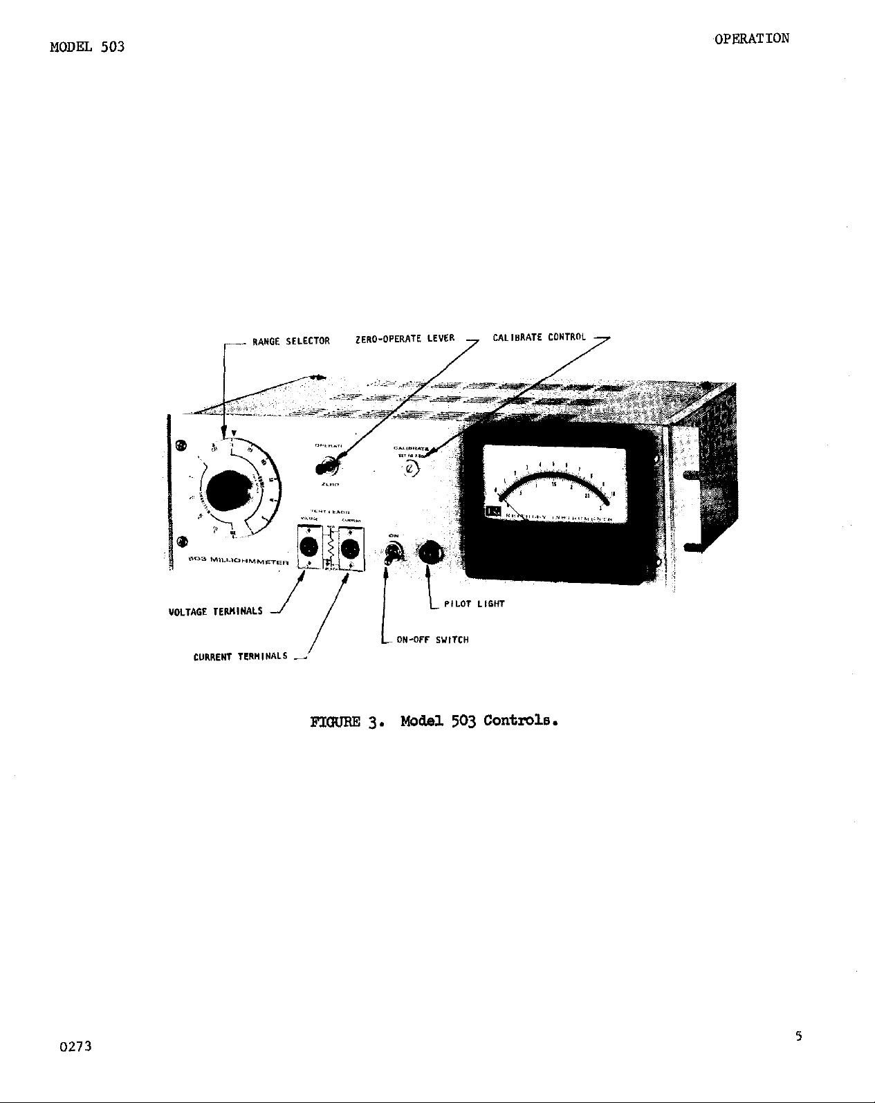
1. RANGE SELEC!lXX
ing from 1 milX.ohm to 300 milJiohms, and seven ohm positions ranging
from lob to lOo0 ohms.
ibration. (Fig. 3)
2. ON:
indicated by the il&minated front panel pilot Lamp. (Fig. 3)
OPERATE-ZERO: This is a lever switch. 1 With the switch in the up
3.
operate) position the 503 is reaw to take measurements. In the down
zero) position the 503 is in zero check.
4.
CALIBMTE:
put voltage of the 503.
justed with a screw driver. (Fig. 3)
VOLTAGE TERMINAL%
5.
the voltmeter circuit.
can be plugged into this receptacle.
6.
CURRENT TERMINAIS:
the current source.
(Fig. 3)
OF CONTROIS AND TERMINALS:
The RANGE SELECTOR has six milliohm positions rang-
A CAL position is provided for Instrument cal-
Toggle switch is the main power switch. Presence of power is
(Fie. 3)
This control is used to calibrate the meter and the out-
It is a recessed slotted control that can be ad-
A 3-pin male receptacle is used for connection to
Pin No. 3 is at chassis ground. Either test lead
(Fig.
3)
A 3-pin male receptacle is used for connection,to
Either test lead can be plugged into this
receptacle.
7.
sis.
OUTHJT:
This provides the output voltage for recording. Pin No. 2 is at ckas-
A two terminal receptacle is located at the rear of the chas-
sis ground.
a.
RESET (503C ONLY): This unlocks the contact circuit. A g-pin recep-
tacle at the rear
of
the chassis provides connections for operation with
the contact meter.
OUTHJTCti
9.
on the chassis behind the front panel.
This is a slotted control located inside the instrument
This adjusts the value of the out-
put voltage for a full scale reading.
10.
11.
MILIJOHMS CALz This is a slotted control located inside the instru-
ment on the chassis behind the front panel.
ibrated using this control.
use.
This is a factory adjusted control and should not require attention.
KJSE:
A fuse extractor post is located on the rear of the instrument.
A low resistance standard is required for its
The milliohm ranges are cal-
For 117 volt operation use a 3 AG, $ amp fuse; for 234~volts use a 3 AG, * amp.
12.
POWER CORD:
The three-wire cord with ,the NEMA approved three-prong
plug provides a ground connection for the cabinet. An adapter to allow
operation
from
two prong outlets is provided.
0273
MODEL 503
,OPERATION
0273
FIm 3.
140del 503 Controls.
5
OPERATION
2-14.0UTLINE OF PFOCELJJRE:
MODEL 503
1. Connect power cord to power source.
nished with the
503.
Power line voltage and frequency range are specified
A three-wire power cord is fur-
on the rear of the instrument.
2. Set ZERO-OPERATE lever to the ZERO position. Set RANGE SELECTOR to
lOOC-ohm position.
Turn on the power.
3,
4.
CONNECTIONS: Each test lead set has two clips, one with a red insu-
lator and the other with a black insulator.
Allow 15 minute warm-up.
When making connections use
both test leads, making sure clips with like color insulators are on the
same side of the sample, (Refer to Figure 2) This is necessary to avoid
meter readings below zero.
Four terminal connections:
a.
The current leads should be attached
to the sample making sure the test current flows through the entire
sample.
This may include leads on the sample. Attach the voltage
leads being sure they are connected only across that portion of the
sample to be measured. If the terminals or the leads of the sample
are included in the voltmeter circuit, their resistance will be
included in the reading. (See Section 2-18)
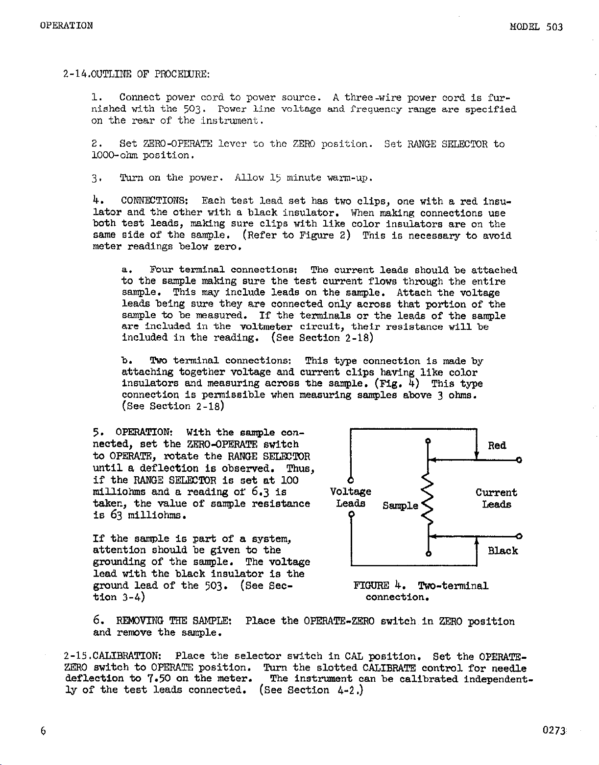
b. Two terminal connections: This type connection is made by
attaching together voltage and current clips having like color
insulators and measuring across the sample. (Fig, 4) This type
connection is permissible when measuring samples above 3 ohms.
(See Section 2-18)
5.
OPERATION: With the sample connected, set the ZERO-OPERATE switch
to OPERATE, rotate the RAWGE SELECTOR
until a deflection is observed.
if the RANGE SELECTOR is set at 100
milliohms and a reading of
6.3
is
taken, the value of sample resistance
IS
63
milliohms.
If the sample is
attention should
grounding of the
part of a system,
be given to the
sample. The voltage
lead with the black insulator is the
E;;; l..d of the
503.
(See Sec-
I
6. FtEMNING ‘I!m s&m&
Place the OPERATE-ZERO switch in ZERO position
and remove the sample.
2-15.CALIBRATION:
ZERO switch to OPERATE position.
deflection to
Place the selector switch in CAL position. Set the OPERATE-
Turn the slotted CALIBRATE control for needle
7.50
on the meter. The inst-nt can be calibrated independent-
ly of the test leads connected. (See Section
Leads
?
FIGURE
connection.
4-2.)
Sample
4.
Two-terminal
Leads
6
0273

MODEL 503
OPERATION
Z-16. OUTPUT.
at ground.
RRATE control on the front panel calibrates the output as well as the meter.
An internal contml R125 OUTPUT CAL is adjusted at the factory to insure track-
ing between the meter and the output voltage.
If it is desired to use a recorder other than 100 millivolts, the output ter-
minals may be shunted with the following values:
After the divider is added to the output, recalibrate the instrument on the
CAL position.
CAL control.
2-lT.MEAsuREMENT OF GROUNDED SAMPLES:
be independently grounded at some point. Since the voltage test lead with the
black clip insulator is at chassis ground, errors could arise in measurement.
1.
using a two-prong power cord adaptor to remove the ground connection to
the power line. Place the instrument so that the cabinet is not touching
ground.
proper insulation.
The 503 is designed to drive a 100 millivolt recorder. The CALI-
Recorder Sensitivity
TEMPORARY MEAsuRe
Connect to the output terminals, observing that pin No. 2 is
(See Figure 14)
Resistance Value
50 m-l
10 mv
lmv
Adjust recorder sensitivity with R125, the internal recorder
FOR OCCASIONALMEASUREMENTS:
If the tilt bail is not used, the rubber feet can provide the
'Z"E
3&Gns
(tap output 7 ohms from ground)
It is possible that the test sample may
Isolate the Model 503
PgRMANENTSET-up:
2.
(such as in rack use) the followlng modification will facilitate such
measurement.
milliohm ranges; the ohm ranges are inoperative.
Remove the chassis ground connection from pin 4 of T-l and pin 3 of J-1.
Then connect pin 3 of J-1 to pin 4 of T-l.
and current test Leads will be isolated from ground.
J-l
The change allows the instrument to operate only on the
FIGlJF?E 5. Modification for unground chassis.
Should it be necessary to unground the chassis,
In this way both the voltage
(Fig. 5)
c
0273
7
 Loading...