

Page 1

Tektronix MDO4034-3 Manual
Get Pricing & Availability at
ApexWaves.com
Call Today: 1-800-915-6216
Email: sales@apexwaves.com
https://www.apexwaves.com/oscilloscopes/tektronix-inc/mdo4000/MDO4034-3
Page 2

x
MDO4000 Series
Mixed Domain Oscilloscopes
ZZZ
User Manual
*P071291300*
071-2913-00
Page 3

Page 4

xx
MDO4000 Series
Mixed Domain Oscilloscopes
ZZZ
User Manual
www.tektronix.com
071-2913-00
Page 5

Copyright © Tektronix. All rights reserved. Licensed software products are owned by Tektronix or its subsidiaries or suppliers, and are
protected by na
tional copyright laws and international treaty provisions.
Tektronix pro
previously published material. Specifications and price change privileges reserved.
TEKTRONIX and TEK are registered trademarks of Tektronix, Inc.
e*Scope, iView, OpenChoice, TekSecure, and TekVPI are registered trademarks of Tektronix, Inc.
MagniVu and Wave Inspector are trademarks of Tektronix, Inc.
PictBridge is a registered trademark of the Standard of Camera & Imaging Products Association CIPA DC-001-2003 Digital Photo
Solutions for Imaging Devices.
Contactin
Tektronix, Inc.
14150 SW Karl Braun Drive
P.O. Box 500
Beaverton, OR 97077
USA
For product information, sales, service, and technical support:
In North America, call 1-800-833-9200.
Worldwide, visit www.tektronix.com to find contacts in your area.
ducts are covered by U.S. and foreign patents, issued and pending. Information in this publication supersedes that in all
g Tektronix
Page 6

MDO4000 Series Oscilloscopes
Warranty
Tektronix warrants that the product will be free from defects in materials and workmanship for a period of three (3) years from the date
of original pu
option, either will repair the defective product without charge for parts and labor, or will provide a replacement in exchange for the
defective product. Batteries are excluded from this warranty. Parts, modules and replacement products used by Tektronix for warranty
work may be ne
rchase from an authorized Tektronix distributor. If the product proves defective during this warranty period, Tektronix, at its
w or reconditioned to like new performance. All replaced parts, modules and products become the property of Tektronix.
In order to ob
period and make suitable arrangements for the performance of s ervice. Customer shall be responsible for packaging and shipping
the defective product to the service center designated by Tektronix, shipping charges prepaid, and with a copy of customer proof of
purchase. T
the Tektronix service center is located. Customer shall be responsible for paying all shipping charges, duties, taxes, and any other
charges for products returned to any other locations.
This warranty shall not apply to any defect, failure or damage caused by improper use or improper or inadequate m aintenance and
care. Tekt
other than Tektronix representatives to install, repair o r service the product; b) to repair damage resulting from improper use or
connection to incompatible equipment; c) to repair any damage or malfunction caused by the use of non-Te ktronix supplies; or
d) to serv
increases the time or difficulty of servicing the product.
THIS WARRANTY IS GIVEN BY TEKTRONIX WITH RESPECT TO THE PRODUCT IN LIEU OF ANY OTHER WARRANTIES,
EXPRESS OR IMPLIED. TEKTRONIX AND ITS VENDORS DISCLAIM ANY IMPLIED WARRANTIES OF MERCHANTABILITY OR
FITNESS
IS THE SOLE AND E XCLU S IVE REMEDY PROVIDED TO THE CUSTOMER FOR BREACH OF THIS WARRANTY. TEKTRONIX
AND ITS VENDORS WILL NOT BE LIABLE FOR ANY INDIRECT, SPECIAL, INCIDENTAL, OR CONSEQUENTIAL DAMAGES
IRRESPE
DAMAGES.
[W16 – 15AUG04]
tain service under this warranty, Customer must notify Tektronix of the defect before the expiration of the warranty
ektronix shall pay for the return of the product to C ustomer if the shipment is to a location within the country in which
ronix shall not be obligated to furnish service under this warranty a) to repair damage resulting from attempts by personnel
ice a product that has been modified or integrated with other products when the effect of such modification or integration
FOR A PARTICULAR PURPOSE. TEKTRONIX’ RESPONSIBILITY TO REPAIR OR REPLACE DEFECTIVE PRODUCTS
CTIVE OF WHETHER TEKTRONIX OR THE VENDOR HAS ADVANCE NOTICE OF THE POSSIBILITY OF SUCH
Page 7

P6616, TPP0500, and TPP1000 Probes
Warranty
Te ktronix w arrants that the product will be free from defects in materials and workmanship for a period of one (1) year from the date of
original purc
option, either will repair the defective product without charge for parts and labor, or will provide a replacement in exchange for the
defective product. Batteries are excluded from this warranty. Parts, modules and replacement products used by Tektronix for warranty
work may be ne
hase from an authorized Tektronix distributor. If the product proves defective during this warranty period, Tektronix, at its
w or reconditioned to like new performance. All replaced parts, modules and products become the property of Tektronix.
In order to ob
period and make suitable arrangements for the performance of service. Customer shall be responsible for packaging and shipping
the defective product to the service center designated by Tektronix, shipping charges prepaid, and with a copy of customer proof of
purchase. T
the Tektronix service center is located. Customer shall be responsible for paying all shipping charges, duties, taxes, and any other
charges for products returned to any other locations.
This warranty shall not apply to any defect, failure or damage caused by improper use or improper or inadequate maintenance and
care. Tekt
other than Tektronix representatives to install, repair or service the product; b) to repair damage resulting from improper use or
connection to incompatible equipment; c) to repair any damage or malfunction caused by the use of non-Tektronix supplies; or
d) to serv
increases the time or difficulty of servicing the product.
THIS WARRANTY IS GIVEN BY TEKTRONIX WITH RESPECT TO THE PRODUCT IN LIEU OF ANY OTHER WARRANTIES,
EXPRESS OR IMPLIED. TEKTRONIX AND ITS VENDORS DISCLAIM ANY IMPLIED WARRANTIES OF MERCHANTABILITY OR
FITNESS
IS THE SOLE AND EXCLUSIVE REMEDY PROVIDED TO THE CUSTOMER FOR BREACH OF THIS WARRANTY. TEKTRONIX
AND ITS VENDORS WILL NOT BE LIABLE FOR ANY INDIRECT, SPECIAL, INCIDENTAL, OR CONSEQUENTIAL DAMAGES
IRRESPE
DAMAGES.
[W15 – 15AUG04]
tain service under this warranty, Customer must notify Tektronix of the defect before the expiration of the warranty
ektronix shall pay for the return of the product to Customer if the shipment is to a location within the country in which
ronix shall not be obligated to furnish service under this warranty a) to repair damage resulting from attempts by personnel
ice a product that has been modifi ed or integrated with other products when the effect of such modification or integration
FOR A PARTICULAR PURPOSE. TEKTRONIX’ RESPONSIBILITY TO REPAIR OR REPLACE DEFECTIVE PRODUCTS
CTIVE OF WHETHER TEKTRONIX OR THE VENDOR HAS ADVANCE NOTICE OF THE POSSIBILITY OF SUCH
Page 8

Table of Contents
General Safety Summary ... ... . .. . .. . ... . .. . .. . ... . .. . .. . ... . .. . .. . ... ... . .. . ... . .. . .. . ... ... . .. . ... ... . .. . .. . ... . .. . ... ... . .. . .. . ... v
Compliance Information.............................................................................................................. vii
EMC Compliance................................................................................................................ vii
Safety Compliance ............................................................................................................. viii
Environmental Considerations................................................................................................... ix
Preface................................................................................................................................. xi
Key Features.....................................................................................................................xi
Conventions Used in This Manual.. . .. . ... . .. . .. . ... . .. . .. . ... . .. . .. . ... . .. . .. . ... . .. . .. . ... . .. . .. . ... . .. . .. . ... . .. . .. . ... . .. . .. xi
Installation.............................................................................................................................. 1
Before Installation................................................................................................................ 1
Operating Considerations........................................................................................................ 5
Operating Positions ..............................................................................................................7
Connecting Probes. .. . .. . ... . .. . ... . .. . .. . ... . .. . .. . . .. . .. . ... . .. . .. . ... . .. . .. . . .. . .. . ... . .. . .. . ... . .. . .. . . .. . .. . ... . .. . .. . ... . .. 8
Securing the Oscilloscope ....................................................................................................... 9
Powering onthe Oscilloscope .................................................................................................. 10
Powering off the Oscilloscope .................................................................................................. 11
Functional Check. ... . .. . ... ... . .. . ... . .. . ... ... . .. . ... ... . .. . ... . .. . .. . ... . .. . .. . ... . .. . .. . . .. . .. . ... . .. . .. . ... . .. . .. . ... . .. . ... 11
Compensating a TPP0500 or TPP1000 Passive Voltage Probe.. . .. . .. . ... . .. . .. . ... . .. . ... . .. . .. . ... . .. . .. . . .. . .. . ... . .. . .. 12
Compensating a non-TPP0500 or non-TPP1000 Passive Voltage Probe. . ... ... . .. . .. . ... . .. . .. . ... . .. . .. . ... ... . .. . .. . ... . 14
Application Module Free Trial... . .. . ... ... . .. . .. . .. . ... . .. . .. . .. . ... ... . .. . .. . ... ... . .. . .. . .. . ... . .. . .. . .. . ... ... . .. . .. . ... ... . . 15
Installing an Application Module.. . .. . .. . ... ... . .. . .. . .. . ... . .. . .. . .. . ... . .. . .. . ... ... . .. . .. . ... ... . .. . .. . ... . .. . .. . .. . ... . .. . .. 15
Changing the Language of the User Interface or Keyboard.. . .. . . .. . .. . ... ... . .. . ... ... . .. . ... . .. . .. . ... . .. . .. . ... . .. . .. . ... . 16
Changing the Date and Time ... . .. . ... . .. . .. . . .. . .. . ... . .. . ... . .. . .. . . .. . .. . ... . .. . ... ... . .. . . .. . .. . ... . .. . ... ... . .. . ... . .. . ... 17
Signal Path Compensation . ... . .. . .. . ... . .. . .. . ... ... . .. . .. . . .. . .. . ... ... . .. . .. . ... . .. . .. . ... . .. . .. . ... . .. . .. . ... ... . .. . ... . .. . 19
Upgrading Firmware ............................................................................................................ 21
Connecting Your Oscilloscope to a C omputer . .. . ... . .. . .. . ... . .. . .. . ... ... . .. . ... ... . .. . .. . ... . .. . .. . ... . .. . .. . ... ... . .. . .. . . 24
Connecting a USB Keyboard to Your Oscilloscope. . ... ... . .. . .. . . .. . .. . ... ... . .. . ... ... . .. . .. . . .. . .. . ... ... . .. . ... ... . .. . .. . . 32
Get Acquainted with the Instrument ................................................................................................. 33
Front-Panel Menus and Controls. . .. . ... . .. . .. . ... ... . .. . .. . ... . .. . .. . ... ... . .. . .. . ... . .. . .. . .. . . .. . .. . ... ... . .. . .. . ... ... . .. . . 33
Front-Panel Connectors .. . ... ... . .. . .. . ... . .. . .. . ... . .. . .. . ... ... . .. . .. . ... . .. . .. . ... ... . .. . .. . ... ... . .. . .. . . .. . .. . ... ... . .. . .. 47
-Panel Connector... . .. . ... . .. . ... ... . .. . ... . .. . ... . .. . ... ... . .. . ... . .. . ... . .. . ... ... . .. . ... . .. . ... . .. . ... ... . .. . ... . .. . ... . 47
Side
Rear-Panel Connectors. . .. . .. . ... . .. . .. . ... ... . .. . .. . ... . .. . .. . .. . . .. . .. . ... ... . .. . .. . ... ... . .. . .. . ... . .. . .. . ... ... . .. . .. . ... . . 48
Acquire the Signal ... . .. . .. . ... . .. . .. . ... . .. . .. . ... ... . .. . .. . ... . .. . ... ... . .. . .. . ... ... . .. . .. . . .. . .. . ... ... . .. . .. . ... ... . .. . .. . . ...... 50
Setting Up Analog Channels.. . .. . ... . .. . ... ... . .. . ... ... . .. . ... . .. . ... ... . .. . ... ... . .. . ... . .. . .. . ... . .. . .. . ... . .. . .. . . .. . .. . ... 50
Using the Default Setup......................................................................................................... 53
Using Autoset ................................................................................................................... 54
Acquisition Concepts............................................................................................................ 55
How the Analog Acquisition Modes Work.. . .. . ... ... . .. . .. . . .. . .. . ... ... . .. . ... ... . .. . .. . . .. . .. . ... ... . .. . ... ... . .. . .. . . .. . .. . 57
Changing the Acquisition Mode, Record Length, and Delay Time. . .. . . .. . .. . ... . .. . .. . ... . .. . .. . . .. . .. . ... ... . .. . ... ... . .. . . 57
Using Roll Mode................................................................................................................. 59
Setting Up a Serial or Parallel Bus ............................................................................................. 60
Setting Up Digital C hannels . .. . .. . ... ... . .. . .. . ... . .. . .. . ... . .. . .. . ... ... . .. . .. . ... . .. . .. . ... . .. . .. . ... . .. . .. . ... ... . .. . .. . ... . 73
Table of Content
s
MDO4000 Series Oscilloscopes User Manual i
Page 9

Table of Content
Trigger Setup . ... ... . .. . ... ... . .. . .. . ... . .. . ... ... . .. . .. . ... ... . .. . ... . .. . .. . ... ... . .. . ... ... . .. . .. . ... . .. . ... ... . .. . .. . ... . .. . ....... 80
Display Waveform or Trace Data .................................................................................................... 96
Analyze Waveform or Trace Data.. . ... . .. . .. . ... . .. . .. . ... ... . .. . ... . .. . .. . ... . .. . .. . ... ... . .. . ... . .. . .. . ... . .. . .. . ... ... . .. . ... . . 117
Save and Recall Information ....................................................................................................... 161
s
When and Why to Turn On MagniVu. . ... ... . .. . ... . .. . ... . .. . ... . .. . ... . .. . ... . .. . .. . ... . .. . ... . .. . ... . .. . ... . .. . .. . . .. . ... ... 75
Using MagniVu . . ... . .. . .. . .. . ... . .. . .. . .. . ... . .. . .. . .. . ... . .. . .. . ... ... . .. . .. . ... ... . .. . .. . ... . .. . .. . .. . ... . .. . .. . .. . ... ... . .. . . 75
Setting Up the RF Inputs.. . .. . ... ... . .. . ... . .. . .. . ... . .. . .. . ... . .. . .. . ... . .. . ... ... . .. . ... ... . .. . .. . . .. . .. . ... . .. . .. . ... ... . .. . . 76
Triggering Concepts............................................................................................................. 80
Choosing a Trigger Type. .. . ... . .. . .. . ... . .. . .. . ... . .. . .. . ... . .. . ... ... . .. . ... ... . .. . ... . .. . .. . ... . .. . .. . ... ... . .. . ... . .. . ... ... 83
Selecting Triggers. . ... . .. . .. . ... ... . .. . .. . ... ... . .. . .. . . .. . .. . ... ... . .. . .. . ... ... . .. . .. . ... . .. . .. . ... ... . .. . .. . ... . .. . .. . ... . .. .84
Triggering on Buses............................................................................................................. 86
Checking Trigger Settings .. . .. . .. . ... ... . .. . .. . ... ... . .. . .. . ... . .. . .. . .. . ... . .. . .. . .. . ... ... . .. . .. . ... . .. . .. . ... ... . .. . .. . ... .. 90
Using Sequence Trigger (A (Main) and B (Delayed)). . ... ... . .. . ... ... . .. . .. . . .. . .. . ... . .. . .. . ... ... . .. . ... . .. . ... ... . .. . .. . .. 91
Starting and Stopping an Acquisition. . .. . .. . ... ... . .. . .. . . .. . .. . ... ... . .. . .. . ... ... . .. . .. . . .. . .. . ... ... . .. . .. . ... . .. . .. . ... . .. . 93
Triggering on the RF Input .. . .. . ... . .. . .. . ... ... . .. . ... . .. . .. . ... ... . .. . ... ... . .. . .. . ... . .. . ... ... . .. . .. . ... . .. . .. . ... . .. . .. . ... 93
Adding and Removing a Waveform ... . .. . .. . ... . .. . .. . ... . .. . .. . ... ... . .. . .. . ... . .. . ... ... . .. . .. . ... . .. . .. . ... . .. . .. . ... . .. . .. 96
Setting the Display Style and Persistence ..................................................................................... 96
Setting Waveform Intensity ................................................................................................... 100
Scaling and Positioning a Waveform......................................................................................... 101
Setting Input Parameters . . ... . .. . .. . ... . .. . .. . ... . .. . .. . ... . .. . .. . ... . .. . .. . ... . .. . .. . ... . .. . .. . ... . .. . .. . ... . .. . .. . ... . .. . .. 102
Positioning and Labeling Bus S ignals . . ... . .. . ... ... . .. . .. . ... . .. . .. . ... . .. . .. . ... . .. . .. . ... ... . .. . .. . . .. . .. . ... ... . .. . .. . ... 106
Positioning, Scaling, and Grouping Digital Channels . .. . .. . . .. . .. . ... ... . .. . .. . ... ... . .. . .. . . .. . .. . ... ... . .. . .. . ... ... . .. . .. 106
Viewing D igital Channels . . .. . .. . ... ... . .. . .. . ... . .. . ... ... . .. . .. . ... ... . .. . .. . . .. . .. . ... ... . .. . .. . ... ... . .. . .. . . .. . .. . ... ... . 108
Annotating the Screen .. . . .. . .. . ... ... . .. . ... ... . .. . .. . . .. . .. . ... ... . .. . ... ... . .. . .. . . .. . .. . ... ... . .. . ... ... . .. . .. . . .. . .. . ... . 108
Viewing the Trigger Frequency . ... . .. . .. . ... . .. . ... . .. . ... ... . .. . ... ... . .. . ... . .. . ... . .. . .. . ... . .. . .. . . .. . .. . ... . .. . ... ... . .. 109
Displaying the Frequency Domain Menu... . .. . ... ... . .. . .. . . .. . .. . ... ... . .. . ... ... . .. . .. . . .. . .. . ... ... . .. . ... ... . .. . .. . . .. . . 110
Using Markers in the Frequency Domain .. . ... ... . .. . .. . ... . .. . .. . .. . ... ... . .. . .. . ... ... . .. . .. . .. . . .. . .. . .. . ... ... . .. . .. . ... 117
Taking Automatic Measurements in the Frequency Domain ... ... . .. . ... ... . .. . ... . .. . ... ... . .. . ... ... . .. . ... . .. . .. . ... . .. . 120
Taking Automatic Measurements inthe Time Domain ...................................................................... 121
Selecting Automatic Measurements inthe Time Domain ................................................................... 122
Customizing an Automatic Measurement in the Time Domain.............................................................. 12
Taking Manual Measurements with Cursors ... . ... . .. . .. . ... . .. . ... ... . .. . ... . .. . ... ... . .. . ... ... . .. . ... . .. . ... ... . .. . ... ... 129
Setting Up a Histogram ....................................................................................................... 133
Using Math Waveforms ....................................................................................................... 136
Using FFT ..................................................................................................................... 137
Using Advanced Math......................................................................................................... 140
Using Spectrum Math . .. . .. . . .. . .. . ... ... . .. . ... ... . .. . ... . .. . .. . ... . .. . .. . ... . .. . .. . ... . .. . ... ... . .. . ... ... . .. . .. . . .. . .. . ... . 141
Using Reference Waveforms and Traces.................................................................................... 142
Using Wave Inspector to Manage Long Record Length Waveforms.. . . .. . .. . ... . .. . .. . ... ... . .. . ... . .. . .. . ... . .. . .. . ... . .. 144
Auto-magnify .. . ... ... . .. . .. . . .. . .. . ... ... . .. . ... ... . .. . .. . . .. . .. . ... ... . .. . ... ... . .. . .. . . .. . .. . ... ... . .. . ... ... . .. . .. . . .. . .. . . 149
Time-Correlated Multi-Domain Display....................................................................................... 150
Limit and Mask Testing........................................................................................................ 154
Analyzing Power . . .. . .. . ... . .. . .. . ... . .. . ... ... . .. . ... ... . .. . ... . .. . ... ... . .. . ... ... . .. . ... . .. . .. . ... . .. . .. . ... . .. . .. . . .. . .. . . 160
Saving a Screen Image....................................................................................................... 163
Saving and Recalling Waveform and Trace Data............................................................................ 164
6
ii MDO4000 Series Oscilloscopes User Manual
Page 10

Table of Content
Saving and Recalling Setups................................................................................................. 167
Saving with One
Managing Drives, Directories, and Files . . .. . ... . .. . .. . ... . .. . .. . ... ... . .. . .. . ... . .. . .. . ... . .. . .. . ... ... . .. . .. . ... . .. . ... ... . 170
Mounting a Network Drive .................................................................................................... 170
Printing a Har
Erasing Oscilloscope Memory ................................................................................................ 177
Using Application Modules .. ... . .. . .. . ... . .. . .. . ... . .. . .. . ... . .. . .. . ... ... . .. . .. . ... . .. . .. . ... . .. . .. . ... ... . .. . .. . ... . .. . .. . ... . .. . 179
Appendix A: M
Appendix B: TPP0500 and TPP1000 500 MHz and 1 GHz 10X Passive Probes Information ... . .. . .. . ... . .. . ... . .. . ... ... . .. . 184
Operating Information......................................................................................................... 184
Connecting
Compensating the Probe with MDO4000 Series Oscilloscopes . .. . ... . .. . .. . ... . .. . .. . ... . .. . .. . ... . .. . ... ... . .. . ... ... . .. 184
Standard Accessories. . .. . .. . ... ... . .. . ... ... . .. . ... . .. . .. . ... . .. . .. . ... . .. . .. . ... . .. . ... ... . .. . ... ... . .. . .. . . .. . .. . ... . .. . .. . 184
Optional A
Replacing the Probe Tip ...................................................................................................... 186
Specifications.................................................................................................................. 187
Performa
Safety Summary .............................................................................................................. 189
Appendix C: P6616 General-Purpose Logic P robe Information . .. . .. . ... . .. . ... ... . .. . ... ... . .. . .. . . .. . .. . ... . .. . .. . ... ... . .. . .. 191
Product D
Connecting the Probe to the Oscilloscope ... . .. . ... ... . .. . .. . ... . .. . .. . ... . .. . .. . ... . .. . .. . ... ... . .. . .. . ... . .. . .. . ... . .. . .. . 191
Connecting the Probe to Your Circuit .. . .. . ... . .. . .. . ... ... . .. . ... . .. . .. . ... ... . .. . ... ... . .. . .. . ... . .. . ... ... . .. . .. . ... . .. . .. 192
nal Check.............................................................................................................. 192
Functio
Typical Application . . .. . .. . ... ... . .. . ... ... . .. . .. . . .. . .. . ... ... . .. . ... ... . .. . .. . . .. . .. . ... ... . .. . ... ... . .. . .. . . .. . .. . ... ... . .. . 193
Accessories ................................................................................................................... 193
cations.................................................................................................................. 194
Specifi
Safety Summary .............................................................................................................. 195
Safety Terms and Symbols in This Manual................................................................................... 195
Index
Button Push ................................................................................................ 169
d Copy.......................................................................................................... 171
DO4000 Specifications............................................................................................. 180
the Probe to the Oscilloscope ................................................................................... 184
ccessories ......................................................................................................... 186
nce Graphs.. . ... . .. . ... ... . .. . ... . .. . ... . .. . .. . ... . .. . ... . .. . ... ... . .. . ... . .. . .. . . .. . .. . ... . .. . ... ... . .. . ... . .. . ... . 187
escription ........................................................................................................... 191
s
MDO4000 Series Oscilloscopes User Manual iii
Page 11

Table of Content
s
iv MDO4000 Series Oscilloscopes User Manual
Page 12

General Safety S
ummary
General Safet
Review the following safety precautions to avoid injury and prevent damage to this product or any products connected to it.
To avoid potential hazards, use this product only as specified.
Only qualified personnel should perform service procedures.
To Avoid Fire or Personal Injury
Use proper power cord. Use only the power cord specified for this product and certified for the country of use.
Connect and disconnect properly. Do not connect or disconnect probes or test leads while they are connected
to a voltage source.
Connect and disconnect properly. De-energize the circuit under test before connecting or disconnecting the current
probe.
Ground th
shock, the grounding conductor must be connected to earth ground. Before making connections to the input or output
terminals of the product, ensure that the product is properly grounded.
Observe all terminal ratings. To avoid fire or shock hazard, observe all ratings and markings on the product. Consult the
product
Connect
e product.
manual for further ratings information before making connections to the product.
the probe reference lead to earth ground only.
y Summary
This product is grounded through the grounding conductor of the power cord. To avoid electric
Do not ap
Power d
must remain accessible to the user at all times.
ply a potential to any terminal, including the common terminal, that exceeds the maximum rating of that terminal.
isconnect.
The power cord disconnects the product from the power source. Do not block the power cord; it
Do not operate without covers. Do not operate this product with covers or panels removed.
Do not operate with suspected failures. If you suspect that there is damage to this product, have it inspected by
qualified service personnel.
Avoid exposed circuitry. Do not touch exposed connections and components when power is present.
Do not operate in wet/damp conditions.
Do not operate in an explosive atmosphere.
Keep product surfaces clean and dry.
Provide proper ventilation.
per ventilation.
pro
Refer to the manual’s installation instructions for details on installing the product so it has
MDO4000 Series Oscilloscopes User Manual v
Page 13

General Safety S
Terms in This Manual
These terms may appear in this manual:
WARNING. Warning s tatements identify conditions or practices that could result in injury or loss of life.
CAUTION. Caution statements identify conditions or practices that could result in damage to this product or other property.
Symbols and Terms on the Product
These terms may appear on the product:
DANGER indicates an injury hazard immediately accessible as you read the marking.
WARNING indicates an injury hazard not immediately accessible as you r ead the marking.
CAUTION indicates a hazard to property including the product.
The following symbol(s) may appear on the product:
ummary
vi MDO4000 Series Oscilloscopes User Manual
Page 14

Compliance Info
rmation
Compliance In
This section lists the EMC (electromagnetic compliance), safety, and environmental standards with which the instrument
complies.
EMC Compliance
EC Declarati
Meets intent of Directive 2004/108/EC for Electromagnetic Compatibility. Compliance was demonstrated to the following
specifications as listed in the Official Journal of the European Communities:
EN 61326-1:2006, EN 61326-2-1:2006. EMC requirements for electrical equipment for measurement, control, and
laborator
CISPR 11:2
IEC 61000
IEC 61000
IEC 61000
IEC 6100
IEC 6100
IEC 6100
on of Conformity – EMC
1234
yuse.
003. Radiated and conducted emissions, Group 1, Class A
-4-2:2001. Electrostatic discharge immunity
-4-3:2002. RF electromagnetic field immunity
-4-4:2004. Electrical fast transient/burst immunity
0-4-5:2001. Power line surge immunity
0-4-6:2003. Conducted RF immunity
0-4-11:2004. Voltage dips and interruptions immunity
formation
5
6
7
EN 61000-3-2:2006. AC power line harmonic emissions
EN 6100
0-3-3:1995.
Voltage changes, fluctuations, and flicker
European contact.
Te ktronix UK, Ltd.
Western Peninsula
Western Road
Bracknell, RG12 1RF
United Kingdom
1
2
3
4
5
6
7
product is intended for use in nonresidential areas only. Use in residential areas may cause electromagnetic interference.
This
Emissions which exceed the levels required by this s tandard may occur when this equipment is connected to a test object.
To ensure compliance with the EMC standards listed here, high quality shielded interface cables should be used.
Instrument rebooting may be experienced where the EUT takes longer than 10 seconds to recover from a transient immunity test.
The instrument will exhibit ≤ 4.0 division waveform displacement and ≤ 8.0 division increase in peak-to-peak noise when subjected
to radiated interference per IEC 61000-4-3.
The instrument will exhibit ≤ 1.0 division waveform displacement and ≤ 2.0 division increase in peak-to-peak noise when subjected
to conducted interference per IEC 61000-4-6.
Performance Criterion C applied at the 70%/25 cycle Voltage-Dip and the 0%/250 cycle Voltage-Interruption test levels
(IEC 61000-4-11).
MDO4000 Series Oscilloscopes User Manual vii
Page 15

Compliance Info
Australia / New Zealand Dec laration of Conformity – EMC
Complies with the EMC provision of the Radiocommunications Act per the following standard, in accordance with ACMA:
CISPR 11:2003. Radiated and Conducted Emissions, Group 1, Class A, in accordance with EN 61326-1:2006 and
EN 61326-2-1:2006.
Australia / New Zealand contact.
Baker & McKenzie
Level 27, AMP
50 Bridge Street
Sydney NSW 2000, Australia
rmation
Centre
Safety Com
EC Declaration of Conformity – Low Voltage
Complianc
Low Volta
EN 61010-
U.S. Nationally Recognized Testing Laboratory Listing
UL 61010-1:2004, 2ndEdition. Standard for electrical measuring and test equipment.
Canadian Certification
CAN/CSA-C22.2 No. 61010-1:2004. Safety requirements for electrical equipment for measurement, control, and
laboratory use. Part 1.
tional Compliances
Addi
IEC 61010-1: 2001. Safety requirements for electrical equipment for measurement, control, and laboratory use.
Equipment Type
pliance
e was demonstrated to the following specification as listed in the Official Journal of the European Communities:
ge Directive 2006/95/EC.
1: 2001. Safety requirements for elec trical equipment for measurement control and laboratory use.
t and measuring equipment.
Tes
Safety Class
Class 1 – grounded product.
viii MDO4000 Series Oscilloscopes User Manual
Page 16

Compliance Info
rmation
Pollution Degree Description
A measure of the contaminants that could occur in the environment around and within a product. Typically the internal
environment inside a product is considered to be the same as the external. Products should be used only in the environment
for which they are rated.
Pollution Degree 1. No pollution or only dry, nonconductive pollution occurs. Products in this category are generally
encapsulated, hermetically sealed, or located in c lean rooms.
Pollution Degree 2. Normally only dry, nonconductive pollution occurs. Occasionally a temporary conductivity that is
caused by condensation must be expected. This location is a typical office/home environment. Temporary condensation
occurs only when the product is out of service.
Pollution Degree 3. Conductive pollution, or dry, nonconductive pollution that becomes conductive due to condensation.
These are sheltered locations where neither temperature nor humidity is controlled. The area is protected from direct
sunshine, rain, or direct wind.
Pollution Degree 4. Pollution that generates persistent conductivity through c onductive dust, rain, or snow. Typical
outdoor locations.
Pollution Degree
Pollution Degree 2 (as defined in IEC 61010-1). Note: Rated for indoor use only.
Installation (Overvoltage) Category Descriptions
Te rminals on this product may have different installation (overvoltage) category designations. T he installation categories are:
Measurement Category IV. For measurements performed at the source of low-voltage installation.
Measurement Category III. For measurements performed in the building installation.
Measurement Category II. For measurements performed on circuits directly connected to the low-voltage installation.
Measurement Category I. For measurements performed on circuits not directly connected to MAINS.
Overvoltage Category
Overvoltage Category II (as defined in IEC 61010-1).
ironmental Considerations
Env
This section provides information about the environmental impact of the product.
Product End-of-Life Handling
serve the following guidelines when recycling an instrument or component:
Ob
Equipment recycling. Production of this equipment required the extraction and use of natural resources. The equipment may
ontain substances that could be harmful to the environment or human health if im properly handled at the product’s end of life. In
c
MDO4000 Series Oscilloscopes User Manual ix
Page 17

Compliance Info
order to avoid release of such substances into the environment and to reduce the use of natural resources, we encourage you to
recycle this pr
rmation
oduct in an appropriate system that will ensure that most of the materials are reused or recycled appropriately.
This symbol ind
to Directives 2002/96/EC and 2006/66/EC on waste electrical and electronic equipment (WEEE) and
batteries. For information about recycling options, check the Support/Service section of the Tektronix Web
site (www.tek
icates that this product complies with the applicable European Union requirements according
tronix.com).
Restriction of Hazardous Substances
This product has been classified as Monitoring and Control equipment, and is outside the scope of the 2002/95/EC RoHS
Directive.
x MDO4000 Series Oscilloscopes User Manual
Page 18

Preface
This manual describes the installation and operation of the following oscilloscopes:
MDO4104-6 MDO4104-3 MDO4054-6 MDO4054-3
Key Features
MDO4000 Mixed Domain Oscilloscopes provide time-correlated acquisition of analog, digital, and RF signals in a single
instrument
in both the time and frequency domains simultaneously. Key features include:
. They can help you verify, debug, and characterize electronic designs by providing views and measurements
A dedicated RF input channel for frequency domain measurements
16 digital channels and four analog channels for time domain measurements
Time-correlated acquisition of analog, digital, and RF signals in a single instrument
The ability to independently set acquisition parameters on the time and frequency domain channels
1 GHz and 500 MHz bandwidths
Preface
Conven
The following icons are used throughout this manual.
Sample rates up to 2.5 GS/s on all analog channels
20 M points record length on all channels
>50,000 waveforms/second display rate
Advanced triggering and analysis: I2C, SPI, USB 2.0, CAN, LIN, FlexRay, RS-232, RS-422, RS-485, UART, I2S, Left
Justified (LJ), Right Justified (RJ), TDM, Ethernet, MIL-STD-1553 (with the appropriate application module), and Parallel
Power analysis application module (optional)
tionsUsedinThisManual
Sequence Step
Front panel power
Connect power
Network
USB
MDO4000 Series Oscilloscopes User Manual xi
Page 19

Preface
xii MDO4000 Series Oscilloscopes User Manual
Page 20

Installation
Before Installation
Unpack the oscilloscope and check that you received all items listed as standard accessories. T he following pages list
recommended accessories and probes, instrument options, and upgrades. Check the Tektronix Web site (www.tektronix.com)
for the most current information.
Standard accessories
Accessory Description
MDO4000 Series Oscilloscopes User Manual
MDO4000 Series Oscilloscopes
Documentation Browser CD
NI LabVIEW SignalExpress™, Tektronix
Edition and Tektronix OpenChoice Desktop
CD
Calibration certificate documenting
traceability to national metrology institute(s),
and ISO9001 quality system registration.
Front Panel Overlay
English (Option L0)
French (Option L1)
Italian (Option L2)
German (Option L3)
Spanish (Option L4)
Japanese (Option L5)
Portuguese (Option L6)
Simplified Chinese (Option L7)
Traditional Chinese (Option L8)
Korean (Option L9)
Russian (Option L10)
Electronic versions of documents, including
the Programmer M anual and the Technical
Reference.
Productivity, analysis, and documentation
software
French (Option L1)
Italian (Option L2)
German (Option L3)
Spanish (Option L4)
Japanese (Option L5)
Portuguese (Option L6)
Simplified Chinese (Option L7)
Traditional Chinese (Option L8)
Korean (Option L9)
Russian (Option L10)
Installation
Tektronix part
number
071-2913-XX
071-2914-XX
071-2915-XX
071-2916-XX
071-2917-XX
071-2918-XX
071-2919-XX
071-2920-XX
071-2921-XX
071-2922-XX
071-2923-XX
063-4367-XX
063-3967-XX
——
335-2376-XX
335-2377-XX
335-2378-XX
335-2379-XX
335-2380-XX
335-2381-XX
335-2382-XX
335-2383-XX
335-2384-XX
335-2385-XX
MDO4000 Series Oscilloscopes User Manual 1
Page 21

Installation
Standard accessories (cont.)
Tektronix part
Accessory Description
For 500-MHz models, one 500-MHz, 10X
passive probe per channel
For 1-GHz models, one 1-GHz, 10X passive
probe per channel
Front Cover
Hard plastic cover to help protect the instrument 200-5130-00
Power Cord North America (Option A0)
Universal Euro (Option A1)
United Kingdom (Option A2)
Australia (Option A3)
Switzerland (Option A5)
Japan (Option A6)
China (Option A10)
India (Option A11)
Brazil (Option A12)
No power cord or AC adapter (Option A99)
Logic probe
One, 16-channel logic probe, with accessories
Probe and accessory pouch Bag to hold probes and related accessories 016-2030-XX
number
TPP0500Probes
TPP1000
161-0104-00
161-0104-06
161-0104-07
161-0104-05
161-0167-00
161-A005-00
161-0306-00
161-0400-00
161-0357-00
——
P6616
Optional accessories
Accessory Description
Aerospace serial triggering and analysis
application module
Audio serial triggering and analysis
application module
Automotive serial triggering and analysis
application module
This module enables triggering on
MIL-STD-1553 serial buses. Also, it provides
digital views of the signal, bus views, bus
decoding, search tools, and decode tables with
time stamp information.
This module enables triggering on I
Justified (LJ), Right Justified (RJ), and TDM
audio buses. Also, it provides digital views of
the signal, bus views, packet decoding, search
tools, and packet decode tables with time
stamp information
This module enables triggering on packet level
information on CAN and LIN serial buses. Also,
it provides a digital view of the signal, bus view,
packet decoding, search tools, and a packet
decode table with time stamp information.
2
S, Left
Tektronix part
number
DPO4AERO
DPO4AUDIO
DPO4AUTO
2 MDO4000 Series Oscilloscopes User Manual
Page 22

Optional accessories (cont.)
Tektronix part
Accessory Description
FlexRay, CAN, and LIN serial triggering and
analysis application module
This module enables triggering on packet level
information in FlexRay, CAN, and LIN buses.
Also, it provides digital views of the signal, bus
views, packet decoding, search tools, packet
decode tables with time stamp information and
eye diagram analysis software.
Computer triggering and analysis application
module
This module enables triggering on RS-232,
RS-422, RS-485 and UART serial buses.
Also, it provides digital v iews of the signal,
bus views, packet decoding, search tools,
and packet decode tables with time stamp
information.
Embedded serial triggering and analysis
application module
This module enables triggering on packet
level information on I
2
C and SPI serial buses.
Also, it provides digital v iews of the signal,
bus views, packet decoding, search tools,
and packet decode tables with time stamp
information.
Ethernet serial triggering and analysis
application module
This module enables triggering on 10BASE-T
and 100BASE-TX buses. Also, it provides
search tools, bus views, and decode tables
with time stamp information.
Limit and mask test application module This module supports limit testing and testing
on telecom standard masks or custom masks.
Power analysis application module
This module supports measurements of power
quality, switching loss, harmonics, ripple,
modulation, safe operating area, and slew rate
(dV/dt and dI/dt).
Universal Serial Bus triggering and analysis
application module
This module enables triggering on packet level
information on USB 2.0 s erial buses. Also, it
provides digital views of the signal, bus views,
bus decoding data in hex, binary, and ASCII,
search tools, and packet decode tables with
time stamp information.
Extended video application module
This module enables triggering on a variety of
standard HDTV signals, as well as on custom
(non-standard) bilevel and trilevel video signals
with 3 to 4,000 lines.
Advanced RF triggering application module This module enables triggering with RF power
as the source for Pulse Width, Timeout, Runt,
Logic, and Sequence triggers
NEX-HD2HEADER
Adapter that routes the channels from a Mictor
connector to 0.1 inch header pins
TPA-BNC TekVPI to TekProbe II BNC Adapter TPA-BNC
TEK-USB-488 Adapter GPIB to USB Adapter TEK-USB-488
number
DPO4AUTOMAX
DPO4COMP
DPO4EMBD
DPO4ENET
DPO4LMT
DPO4PWR
DPO4USB
DPO4VID
MDO4TRIG
NEX-HD2HEADER
Installation
MDO4000 Series Oscilloscopes User Manual 3
Page 23

Installation
Optional accessories (cont.)
Tektronix part
Accessory Description
Rackmount kit Adds rackmount brackets RMD5000
Soft transit case Case for carrying instrument ACD4000B
Hard transit case
MSO4000B, DPO4000B, and MDO4000
Series Oscilloscopes Programmer Manual
MDO4000 Series Oscilloscopes Technical
Reference Manual
MDO4000 Series Oscilloscopes Service
Manual
MSO4000B, DPO4000B, and MDO4000
Series A pplication Module Installation
Instructions
DPO3PWR and DPO4PWR Power
Measurement Module User Manual
MDO4000 Series Oscilloscopes
Declassification and Security Instructions
TPA-N-VPI Adapter
Traveling case, which requires use of the soft
transit case (ACD4000B)
Describes commands for remote control of the
oscilloscope. Available electronically on the
Documentation Browser CD or for download
from www.tektronix.com/manuals.
Describes the oscilloscope specifications
and performance verification procedure.
Available electronically on the Documentation
Browser CD or for download from
www.tektronix.com/manuals.
Service information on MDO4000 Series
oscilloscopes
Describes how to install application modules
on your oscilloscope
English (Option L0)
French (Option L1)
Italian (Option L2)
German (Option L3)
Spanish (Option L4)
Japanese (Option L5)
Portuguese (Option L6)
Simplified Chinese (Option L7)
Traditional Chinese (Option L8)
Korean (Option L9)
Russian (Option L10)
Describes how to sanitize or remove memory
devices from the Tektronix MD4000Series
oscilloscopes.
Adapter from N connection (RF input) to
TekVPI probe.
number
HCTEK54
077-0510-XX
077-0583-XX
077-0585-XX
071-2136-XX
071-2631-XX
077-0235-XX
077-0236-XX
077-0237-XX
077-0238-XX
077-0239-XX
077-0240-XX
077-0241-XX
077-0242-XX
077-0243-XX
077-0244-XX
077-0584-00
TPA-N-VPI
The MDO4000 Series oscilloscopes work with multiple optional probes. (See page 8, Connecting Probes.) Check the
Tektronix Web site (www.tektronix.com) for the most current information.
4 MDO4000 Series Oscilloscopes User Manual
Page 24

Operating Considerations
Installation
MDO4000 Serie
Operating Li
Volts
100-240
115
Mains input
Maximum Power Consumption: 225 W
Weight:
5.0 kg (11.
cover
Height, feet folded in, handle folded down:
229 mm (9.
Width, from handle hub to handle hub: 439 mm
(17.3 in)
Depth, f
(5.8 in)
Depth, from back of feet to front of front cover: 155
mm (6.1 i
Temperature:
Operat
Non-operating: -20 °C to +60 °C (-4 °F to 140 °F)
0 lbs), standalone instrument, without front
rom back of feet to front of knobs: 147 mm
n)
ing:+0°Cto+50°C(+32°Fto122°F)
s Osc illoscopes
ne Frequency and Voltage Range
Hz
50-60
400
voltage range: 100 V - 240 V
0in)
MDO4000 Se
ries
ity:
Humid
Operating: High: 40 °C to 50 °C (104 °F to 122 °F),
10% to 60% RH
ting: Low: 0 °C to 40 °C (32 °F to 104 °F), 10
Opera
to 90% RH
Non-operating: High: 40 °C to 60 °C (104 °F to
F), 5 to 60% RH
140 °
Non-operating: Low: 0 °C to 40 °C (32 °F to 104 °F),
5to90%RH
Altitude:
Operating: 3,000 m (about 9,843 ft)
-operating Altitude: 12,000 m (39,370 ft)
Non
Pollution Degree: 2, Indoor use only
MDO4000 Series Oscilloscopes User Manual 5
Page 25

Installation
Acquisition System: 1 MΩ
The maximum input voltage at the BNC, 300 V
Derate at 20 dB
/decade between 4.5 MHz and 45 MHz.
. Installation Category II.
RMS
Derate at 14 dB/decade between 45 MHz and 450 MHz.
Above 450 MHz, 5 V
RMS
.
Acquisition System: 50 Ω
The maximum
input voltage at the BNC: 5 V
, with peaks ≤ ±20 V (DF ≤ 6.25%)
RMS
P6616: Digital Probe Inputs
The absolut
e maximum input voltage: ±42 V
Peak
.
Dedicated RF Input:
The maximu
m operating voltage: ±40 V
.
DC
6 MDO4000 Series Oscilloscopes User Manual
Page 26

Installation
CAUTION. To ensure proper cooling, keep the sides and rear of the instrument clear of obstructions. Ventilation clearance
should be at least 51 mm (2 in) on the left side, when looking at the front of the instrument, and on the rear of the instrument
Find more information on MDO4000 Series oscilloscope specifications in Appendix A. (See page 180, Appendix A:
MDO4000 Specification
s.).
Find information on T
500 MHz and 1 GHz 10X Passive Probes Information.)
Find information on P6616 probes in Appendix C. (See page 191, Appendix C: P6616 General-Purpose Logic Probe
Information.)
PP0500/TPP1000 probes in Appendix B. (See page 184, Appendix B: TPP0500 and TPP1000
Cleaning
Inspect the oscilloscope and probes as often as operating conditions require. To clean the exterior surface, perform the
following steps:
1. Remove loose dust on the outside of the oscilloscope and probes with a lint-free cloth. Use care to avoid scratching
the display.
2. Use a soft cloth dampened with water to clean the oscilloscope. Use an aqueous solution of 75% isopropyl alcohol
for more efficient cleaning.
CAUTION. Avoid getting moisture inside the unit during external cleaning. Use only enough cleaning solution to dampen
the cloth or swab.
CAUTION. To avoid damage to the surface of the oscilloscope or probes, do not use any abrasive or chemical cleaning
agents.
Operating Positions
Use the handle and front flip f
always have the handle in a down position.
eet to place the oscilloscope in a convenient operating position. When the feet are extended,
MDO4000 Series Oscilloscopes User Manual 7
Page 27

Installation
Connecting Probes
The oscilloscope supports probes with the following:
1. Tektronix Versatile Probe Interface
(TekVPI)
These probes support two-way
communication with the oscilloscope
through on-screen menus and remotely
through programmable support. The
remote control is useful in applications
like ATE where you want the system to
preset probe parameters.
2. Tektronix Versatile Probe Interface
(TekVPI) for Passive Probes
These probes build upon the functionality
of the TekVPI interface. Each probe
is matched with its c orresponding
oscilloscope channel, allowing the
oscilloscope to optimize the signal input
path. This provides AC compensation
across the frequency band.
3. TPA-BNC Adapter
The TPA-BNC Adapter allows you to
use TEKPROBE II probe capabilities,
such as providing probe power, and
passing scaling and unit information to
the oscilloscope.
4. BNC Interfaces
Some of these use TEKPROBE
capabilities to pass the waveform signal
and scaling to the oscilloscope. Some
only pass the signal and there is no other
communication.
5. Logic Probe Interface
The P6616 probe provides 16 channels
of digital (on or off state) information.
6. The TPA-N-VPI Adapter allows you to
use TekVPI probes in the RF input.
For more information on the many probes available for use with MDO4000 Series oscilloscopes, refer to www.tektronix.com.
8 MDO4000 Series Oscilloscopes User Manual
Page 28

Securing the Oscilloscope
1. Use a standard laptop computer style
security lock
to your location.
to secure your oscilloscope
Installation
MDO4000 Series Oscilloscopes User Manual 9
Page 29

Installation
Powering on the Oscilloscope
Ground the Oscilloscope and Yourself
To power on the instrument, connect the power cord that was provided with the instrument to the power connector on the
rear panel. C
power cord from the instrument.
onnect the power cord to a properly grounded electrical outlet. To power off the instrument, remove the
Grounding th
same ground as any circuits that you are testing.
If you are wo
components, ground yourself. Static
electricity that builds up on your body
can damage
Wearing a grounding strap safely sends
static charges on your body to earth ground.
To connect the power cord and power on the oscilloscope:
e oscilloscope is necessary for safety and to take accurate measurements. The oscilloscope needs to share the
rking with static sensitive
static-sensitive components.
10 MDO4000 Series Oscilloscopes User Manual
Page 30

Powering off the Oscilloscope
To power off the oscilloscope and remove the power cord:
Installation
Functional Check
Perform this quick functional check to verify that your oscilloscope is operating correctly.
1. Connect the oscilloscope power cable
as described in Powering On the
Oscilloscope. (See page 10.)
2. Power on the oscilloscope.
MDO4000 Series Oscilloscopes User Manual 11
Page 31

Installation
3. Connect the probe connector to
oscilloscope channel 1 and the probe tip
and reference
terminals on the oscilloscope front panel.
4. Push Default Setup.
5. Push Autoset. The screen should now
display a
2.5 V at 1 kHz.
If the signal appears but is misshapen,
perform
the probe. (See page 14, Compensating
a non-TPP0500 or non-TPP1000
Passive
If no signal appears, rerun the procedure.
If this does not remedy the situation,
have th
service personnel.
lead to the PROBE COMP
square wave, approximately
the procedures for compensating
Voltage Probe.)
e instrument serviced by qualified
Compensating a TPP0500 or TPP1000 Passive Voltage Probe
The MDO4000 Series oscilloscopes can automatically compensate TPP0500 and TPP1000 probes. This eliminates the need
for manual probe compensation, as is typically performed with other probes.
Each compensation generates values for a specific probe and channel combination. If you want to use the probe on another
channel and desire to compensate the new probe-channel pair, you must run a new set of compensation steps for that new
combination.
1. Connect the oscilloscope power cable. (See
page 10, Powering on the Oscilloscope.)
2. Power on the oscilloscope.
12 MDO4000 Series Oscilloscopes User Manual
Page 32

3. Connect the probe connector to the
oscilloscope channel and the probe tip
and reference
lead to the PROBE COMP
terminals on the oscilloscope front panel.
NOTE. Connect only one probe at a time to the
probe comp te
rminals.
4. Push a front-panel button for an input
channel connected to the probe you wish to
compensate. (1, 2, 3,or4)
Installation
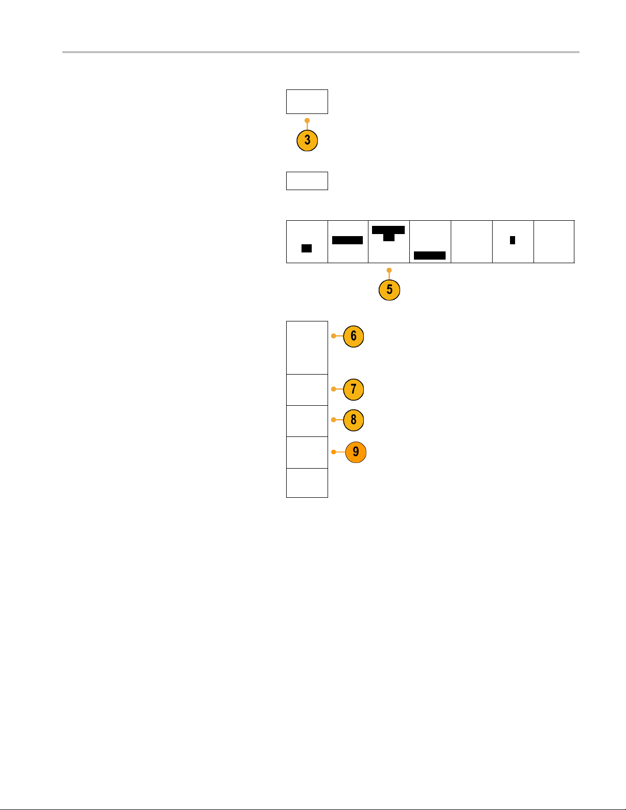
5. Notice on the lower menu that the
oscilloscope has automatically set the probe
termination value
6. Push More repeatedly to select Probe
Setup from the resulting pop-up menu.
Coupling
DC|AC
Term i n a -
tion set by
TPP1000
Invert
On|
Off
Bandwidth
Full
Label
More
MDO4000 Series Oscilloscopes User Manual 13
Page 33

Installation
TPP1000
Probe
Setup
SN:
000001
Atten: 10X
7. Notice that the compensation status starts
as Default.
8. Push Compens
ate probe and follow the
instructions that appear on the display.
Compen-
sation
Status
Default
Compen-
sate probe
for 1
Measure
Current
Yes |
No
When compensating TPP0500/TPP1000 probes on the MDO4000 Series oscilloscopes:
Each compensation generates values for a specific probe and channel combination. If you want to use the probe on
another ch
annel and desire to compensate the new probe-channel pair, you must run a new set of compensation steps.
Compe
Each chann
el can store compensation values for 10 individual probes. If you try to compensate an 11th probe on a
channel, the oscilloscope will delete the values for the least recently used probe and add the values for the new probe.
The oscilloscope will assign default compensation values to a TPP0500 or TPP1000 probe connected to the Aux
In channel.
NOTE. Af
actory calibration will delete all stored compensation values
NOTE. A probe compensation failure is most likely due to intermittent connection of the probe tip or ground connection
during the probe compensation operation. If a failure occurs, the oscilloscope will re-use the old probe compensation values,
existed prior to the failed probe compensation operation.
if they
nsating a non-TPP0500 or non-TPP1000 Passive Voltage Probe
Whenever you attach a passive voltage probe for the first time to any input channel, compensate the probe to match it to
the corresponding oscilloscope input channel.
If you are interested in using the automatic probe compensation procedure described above for the TPP0500 and TPP1000 probes
(See page 12, Compensating a TPP0500 or TPP1000 Passive Voltage Probe.) on a non-TPP0500/TPP1000 Tektronix passive
probe, check the instruction manual for your probe to see if it qualifies. Otherwise, to properly compensate your passive probe:
1. Follow the steps for the functional
check. (See page 11, Functional
Check.)
14 MDO4000 Series Oscilloscopes User Manual
Page 34

2. Check the shape of the displayed
waveform to determine if your
probe is prope
rly compensated.
Properly compensated
Under compensa
ted
Over compensat
Installation
ed
3. If necessary,
Repeat as needed.
adjust your probe.
Quick Tips
Use the shortest possible ground lead
and signal path to minimize probe-induced
ringing a
signal.
nd distortion on the measured
Signal with a short ground lead
ith a long ground lead
Signal w
Application Module Free Trial
A 30-day free trial is available for all application module licenses not installed in your oscilloscope. The trial period begins
when you power on the oscilloscope for the first time.
After 30 days, you must purchase the module if you want to continue using the application. To see the date when your free
trial period expires, push the front panel Utility button, push the lower-bezel Utility Page button, use multipurpose knob a to
select Config, and push the lower-bezel About button.
Installing an Application Module
CAUTION. To avoid damage to the oscilloscope or application module, observe ESD (electrostatic discharge) precautions.
(See page 10, Powering on the Oscilloscope.)
Turn off the oscilloscope power while removing or adding an application module.
(See page 11, Powering off the Oscilloscope.)
MDO4000 Series Oscilloscopes User Manual 15
Page 35

Installation
Optional application module packages extend the capability of your oscilloscope.
You can physically install up to four application m odules at one time. Application modules go into the two slots with windows
in the upper ri
slots, install the module with the label facing away from you.
Each module has a license, which you can optionally transfer between your application modules and oscilloscope. You can
keep each license in the module, which will allow you to move the module from one instrument to another.
Alternatively, you can move the l icense from the module to the oscilloscope. This approach will allow you to store the module
separately f
your oscilloscope simultaneously.
To transfer a license from a module to your oscill oscope or from your oscilloscope to a module:
1. Turn off the power to the oscilloscope. Insert the application modules in the oscilloscope. Turn on the power.
2. Push the front-panel Utility button. If needed, push the lower-menu Utility Page button and turn multipurpose knob
a to select Config. Push the lower menu Application Module Licenses button and the appropriate side-menu
buttons to
up to four licenses at one time.
3. After you turn off the power to the oscilloscope, you can remove the physical application module from the oscilloscope.
Refer to the MSO4000B, DPO4000B, and MDO4000 Series Oscilloscopes Application Module Installation Instructions that
came with your application module for instructions on installing and testing an application module.
ght corner of the front panel. Two additional slots are directly behind the two that you can see. To use these
rom the oscilloscope for safe keeping. This approach will also allow you to use more than four applications on
transfer the license from the module to the oscilloscope or from the oscilloscope to the module. Transfer
NOTE. If
you transfer the license back from the oscilloscope to the m odule. Consider putting the physical module in an envelope
or other storage with a label with the date, the module name, and the model and serial number of the oscilloscope, which
holds it
and wonders why it does not work.
you transfer a license from a module to an oscilloscope, the module w ill not work on another oscilloscope until
s license. This will help prevent trouble later if someone finds the module, installs it in some other oscilloscope,
Changing the Language of the User Interface or Keyboard
To change the language of the oscilloscope user interface or keyboard, and to change the front-panel button labels through
the use of an overlay:
1. Push Utility.
2. Push Utility Page.
Utility
Page
3. Turn multipurpose knob a and select Config.
16 MDO4000 Series Oscilloscopes User Manual
Config
Page 36

Installation
4. Push Language from the resulting
lower-bezel menu.
5. Push Menus from the resulting side menu
and turn mul
tipurpose knob a to s e lect the
desired language for the user interface.
6. Push USB Ke
yboard from the resulting side
menu and turn multipurpose knob a to select
the desired language version of keyboard
to use.
7. If you choose to use an English user
ce, be sure that the plastic front-panel
interfa
overlay is removed.
If you choose a language other than English,
e plastic overlay for the language
place th
that you desire over the front panel to display
labels in that language.
Utility
Page
Config
Language
Menus
(a) English
USB
Keyboard
English
Language
Set Date &
Time
TekSecure
Erase
Memory
About
Chan
ging the Date and Time
To set the internal clock with the current date and time:
1. Push Utility.
MDO4000 Series Oscilloscopes User Manual 17
Page 37

Installation
2. Push Utility P
age.
3. Turn multipurpose knob a and select Config.
4. Push Set Dat
e&Time.
5. Push the side-bezel buttons and turn both
pose knobs (a and b)tosetthetime
multipur
and date values.
6. Push OK Set Date & Time.
Utility
Page
Config
Utility
Page
Config
Display
Date &
Time
On|Off
Hour
4
Minute
44
Month
May
Day
3
Year
2011
OK Set
Date &
Time
Language
Set Date &
Time
TekSecure
Erase
Memory
About
18 MDO4000 Series Oscilloscopes User Manual
Page 38

Signal Path Compensation
Signal Path Compensation (SPC) corrects for DC inaccuracies caused by temperature variations and/or long-term drift.
Run the compensation whenever the ambient temperature has changed by more than 10 °C (18 °F) or once a week
if you use vertical settings of 5 mV/division or less. Failure to do so may result in the instrument not meeting warranted
performance levels at those volts/div settings.
Signal Path Compensation for Time and Frequency Domain s
To compensate the signal path:
1. Warm up the oscilloscope for at least
20 minutes. Remove all input signals
(probes and cables) from channel inputs.
Input signals with AC components adversely
affect SPC.
Installation
2. Push Utility.
3. Push Utility Page.
4. Turn multipurpose knob a and select
Calibration.
Utility
Page
Calibration
MDO4000 Series Oscilloscopes User Manual 19
Page 39

Installation
5. Push Signal Path from the lower-bezel
menu.
6. Push OK Compensate Signal Paths from
the resulting side-bezel menu.
The calibra
tion will take approximately
10 minutes to complete.
7. After cali
bration, verify that the status
indicator on the lower-bezel menu displays
Pass.
If it does not, then recalibrate the instrument
or have the instrument serviced by qualified
service p
ersonnel.
Service personnel use the factory calibration
ns to calibrate the internal voltage
functio
references of the oscilloscope using
external sources. Contact your Tektronix
fice or representative for assistance
field of
with factory calibration.
Utility
Page
Calibration
OK Com-
pensate
Signal
Paths
Utility
Page
Calibration
Signal
Path
Pass
Signal
Path
Pass
Factory
Pass
Factory
Pass
NOTE. Signal Path Compensation does not include calibration to the probe tip. (See page 14, Compensating a
non-TPP0500 or non-TPP1000 Passive Voltage Probe.)
Signal Path Compensation for Frequency Domain Only
The signal path compensation (SPC) described above runs on both the time and the frequency domain inputs. If you only
want to compensate the RF input, you can save time by running SPC only on the RF input and skipping the time domain
part. You can do this as follows:
1. As with the time and frequency calibration,
warm up the oscilloscope for at least
20 minutes. Remove all input signals
(probes and cables) from the RF input.
2. Push RF to bring up the Frequency Domain
menu.
20 MDO4000 Series Oscilloscopes User Manual
Page 40

Installation
3. Push More to select Compensate SIgnal
Path.
4. On the resulti
ng side menu, push OK.
Compensate RF Signal Path.
Upgrading Firmware
To upgrade the firmware of the oscilloscope:
1. Open up a Web browser and go to
www.tektronix.com/software. P roceed to
the software finder. Download the latest
firmware for your oscilloscope on your PC.
e files and copy the firmware.img
Unzip th
file into the root folder of a USB flash drive
or USB hard drive.
Spectrum
Traces
RF Versus
Time
Traces
Spectro-
gram
On
Spectrum
Triggered
Detection
Method
Auto
Edit Labels
More
2. Power off your oscilloscope.
MDO4000 Series Oscilloscopes User Manual 21
Page 41

Installation
3. Insert the USB flash or hard drive into the
front-panel USB port on your oscilloscope.
4. Power on the oscilloscope. The instrument
automatic
firmware and installs it.
If the instrument does not install the
firmware,
problem continues, try a d ifferent model of
USB flash or hard drive. Finally, if needed,
contact
ally recognizes the replacement
rerun the procedure. If the
qualified service personnel.
NOTE. Do not power off the oscilloscope or
remove the USB drive until the oscilloscope
finishes
5. Power off the oscilloscope and remove the
installing the firmware.
USB flash or hard drive.
22 MDO4000 Series Oscilloscopes User Manual
Page 42

Installation
6. Power on the osc
7. Push Utility.
8. Push Utility Page.
illoscope.
Utility
Page
9. Turn mu
ltipurpose knob a and select Config.
10. Push About. The oscilloscope displays the
firmware version number.
11. Confirm that the version number matches
that of the new firmware.
Config
Utility
Page
Config
Language
English
Set Da
Time
te &
TekSe
Erase
Memory
cure
About
MDO4000 Series Oscilloscopes User Manual 23
Page 43

Installation
Connecting Your Oscilloscope to a Computer
Connect your oscilloscope directly to a computer to let the PC analyze your data, collect screen images, or to control your
oscilloscope. (See page 163, Saving a Screen Image.) (See page 164, Saving and Recalling Waveform and Trace D ata.)
Three ways to connect your oscilloscope to a computer are through the VISA drivers, the e*Scope Web-enabled tools, and
a socket server. Use VISA to communicate with your oscilloscope from your computer through a software application,
such as Tektronix OpenChoice Desktop®. Use e*Scope to communicate with your oscilloscope through a Web browser,
such as Microsoft Internet Explorer.
Using VISA
VISA lets yo
runs on your PC, such as Microsoft Excel, National Instruments LabVIEW, Tektronix OpenChoice Desktop software, or a
program of your own creation. You can use a common communications connection, such as USB, Ethernet, or GPIB,
to connect
To set up VISA communications between your oscilloscope and a computer:
1. Load the VISA drivers on your computer.
2. Connect the oscilloscope to your computer
u use your MS-Windows computer to acquire data from your oscilloscope for use in an analysis package that
the computer to the oscilloscope.
Also, load your application, such as
OpenChoice Desktop.
You will find the drivers and OpenChoice
Desktop software on the appropriate CD
that comes with your oscilloscope or at
the Tektronix software finder Web page
(www.tektronix.com).
with the appropriate USB or Ethernet cable.
To communicate between the oscilloscope
and a GPIB system, connect the oscilloscope
to the TEK-USB-488 GPIB-to-USB Adapter
with a USB cable. Then connect the adapter
to your GPIB system with a GPIB cable.
Cycle the power on the oscilloscope.
24 MDO4000 Series Oscilloscopes User Manual
Page 44

3. Push Utility.
Installation
4. Push Utility Page.
5. Turn multipurpose knob a and select I/O.
6. If you are using USB, the system sets itself
up automatically for you, if USB is enabled.
Check USB on the lower-bezel menu to
be sure t
hat USB is enabled. If it is not
enabled, push USB. Then push Connect to
Computer on the side-bezel menu.
7. To use Ethernet, push the Ethernet & LXI
lower-bezel button.
e side-bezel buttons to adjust
Use th
your network settings, as needed. For
more information, see the e*Scope setup
mation below.
infor
Utility
Page
I/O
Utility
Page
I/O
USB
Computer
Ethernet &
LXI
Network
Configura-
tion
Automatic
Socket
Server
GPIB
1
8. If you want to change socket server
meters, push Socket Server and enter
para
new values through the resulting side-bezel
menu.
9. If you are using GPIB, push GPIB. Enter
the GPIB address on the side-bezel menu,
ing multipurpose knob a.
us
Talk/Listen
ress
Add
(a) 1
This will set the GPIB address on an
tached TEK-USB-488 Adapter.
at
MDO4000 Series Oscilloscopes User Manual 25
Page 45

Installation
10. Run your application software on your
computer.
Quick Tips
Your oscilloscope shipped with a CD that contains a variety of Windows-based software tools for efficient connectivity
between your oscilloscope and your computer. These include toolbars that speed connectivity with Microsoft Excel and
Word. There are also two standalone acquisition programs called NI LabVIEW SignalExpress™, Tektronix Edition and
Tektronix OpenChoice Desktop.
The rear-panel USB 2.0 device port is the correct USB port for computer connectivity. Use the rear- and front-panel USB
2.0 host ports to connect your oscilloscope to USB flash drives. Use the USB Device port to connect your oscilloscope
to a PC or a PictBridge printer.
USB Host port
USB Device port
Using the LXI Web Page and e*Scope
With e*Scope, you can access any Internet-connected MDO4000 Series oscilloscope from a web browser on your computer.
To set up e*Scope communications between your oscilloscope and a Web browser running on a remote computer:
1. Connec
2. Push Utility.
t the oscilloscope to your computer
network with an appropriate Ethernet cable.
26 MDO4000 Series Oscilloscopes User Manual
Page 46
Installation
3. Push Utility P
age.
4. Turn multipurpose knob a and select I/O.
5. Push Ether
net & LXI.
6. View the top side-menu item to determine
the condition of the LAN. An indicator turns
r good status and red if the device
green fo
detects a fault.
7. Push LAN
Settings to display the network
parameters con figured on your oscilloscope.
Utility
Page
I/O
Utility
Page
I/O
Ethernet
LXI LAN
Status
LAN
Setting
&
s
USB
Computer
Ethernet &
LXI
Network
Configura-
tion
Automatic
Socket
Server
GPIB
1
8. Push LA
N Reset to restore the LAN defaults
to your oscilloscope.
9. Push Te
st Connection to check if your
oscilloscope can find an attached network.
10. Push m
ore to see another page of
side-menu items.
LAN Reset
Test Con-
nection
more 1 of 2
MDO4000 Series Oscilloscopes User Manual 27
Page 47

Installation
11. Push Change Names to change the name
of the oscillo
scope, the network domain, or
the service name.
12. Push Change E
thernet & LXI Password to
change the name of the password.
13. Push Ch ange
e*Scope Password to use
the LXI password to also protect your
oscilloscope from changes made to LAN
settings fr
om a Web browser.
14. S tart your browser on your remote computer.
In the bro
wser address line, enter the host
name, a dot, and the domain name together.
Alternatively, just enter the IP address of
rument. Either way, you should then
the inst
see the LXI Welcome page on your Web
browser on your computer screen.
Ethernet &
LXI
Change
Names
Change
Ethernet
&LXI
Password
Change
e*Scope
Password
a Enabled
more
2of2
15. Click “Network Configuration” to view and
edit the network configuration settings. If
using a password and changing
you are
your settings, you need to know that the
default user name is “lxiuser”.
28 MDO4000 Series Oscilloscopes User Manual
Page 48

16. For e*Scope, click the Instrument Control
(e*Scope) link on the left side of the LXI
Welcome page.
tab (or window) open in your browser with
e*Scope running.
You should then see a new
Installation
Using a Socket Server
et server provides two-way communication over an Internet Protocol-based computer network. You can use your
Asock
oscilloscope’s socket server feature to let your oscilloscope communicate with a remote-terminal device or computer.
To set up and use a socket server between your oscilloscope and a remote terminal or computer:
1. Connect the oscilloscope to your computer
ork using an appropriate Ethernet
netw
cable.
MDO4000 Series Oscilloscopes User Manual 29
Page 49

Installation
2. Push Utility.
3. Push Utility Page.
4. Turn multipurpose knob a and select I/O.
5. Push Socket Server.
6. On the resulting Socket Server side menu,
push the top entry to highlight Enabled.
7. Choose whether the protocol should be
None or Terminal.
unication session run by a human
Acomm
at a keyboard typically uses a terminal
protocol. An automated session might
le its own communications without such
hand
protocol from the oscilloscope.
8. If required, change the port number by
rotating multipurpose knob a.
9. If required, press OK to set the new port
number.
Utility
Page
Utility
Page
I/O
Socket
Server
Enabled
Disabled
col
Proto
None
Terminal
Current
Port 4000
Select Port
000
(a) 4
OK
Port
Set
USB
Computer
Ethernet &
LXI
Network
Configura-
tion
Manual
Socket
Server
GPIB
1
30 MDO4000 Series Oscilloscopes User Manual
Page 50

10. After you have set up the socket server
parameters, the computer is now ready to
communicate w
ith the oscilloscope. If you
are running an MS Windows PC, you could
run its default client Te lnet, which has a
command inte
by typing “
rface. One way to do this is
Telnet” in the Run window. The
Telnet window will open on the PC.
Installation
NOTE. On MS Wi
ndows 7, you must first
enable Telnet in order for Telnet to work.
11. Start a terminal session between your
computer and your oscilloscope by typing in
an open com
mand with the oscilloscope’s
LAN address and port #.
You can obtain the LAN address by pushing
the Ether
net & LXI bottom menu item and
the resulting LAN Settings side menu
item to view the resulting Ethernet and LXI
Settings
screen. You can obtain the port #
by pushing the Socket Server bottom menu
item and viewing the Current Port side
menu ite
m.
For example, if the oscilloscope IP address
was
123.45.67.89 and the post #
was the
default of 4000, you could open
a session by writing into the MS Windows
Te lnet screen:
illoscope will send a help screen to the
The osc
o 123.45.67.89 4000.
computer when it has finished connecting.
MDO4000 Series Oscilloscopes User Manual 31
Page 51

Installation
12. You can now type
NOTE. Do not use the computer’s backspace
key during a
the oscilloscope.
Connecti
You can connect a USB keyboard to a USB Host port on the rear or front panel of the oscilloscope. The oscilloscope will
detect the keyboard, even if it is plugged in while the oscilloscope is powered on.
You can use the keyboard to quickly create names or labels. You can bring up the Label menu through the lower-bezel label
button of the Channel or Bus menus. Use the arrow keys on the k eyboard to move the insertion point, and then type in a
name or label. Labeling channels and buses makes the information on the screen easier to identify.
in a standard query, such
as,
*idn?.
The Telnet session window will respond by
displaying a c
haracter string describing your
instrument.
You can type in more queries and view
more results
using this Telnet session
window. You can find the syntax for relevant
commands, queries and related status
codes in the M
SO4000B, DPO4000B, and
MDO4000 Series Programmer Manual.
n MS Windows Telnet session with
ng a USB Keyboard to Your Oscilloscope
To choose whether to use a keyboard with a United States (US) key layout or one with an alternative layout.
1. Push Utility.
2. Push Utility Page.
Utility
Page
Config
Language
English
Set Date &
Time
TekSecure
Erase
Memory
About
3. Turn multipurpose knob a and select Config.
4. Push Language from the r esulting
lower-bezel menu.
5. Push USB Keyboard from the resulting side
menu.
6. Turn multipurpose knob a and select the
desired keyboard layout style from the
resulting menu.
32 MDO4000 Series Oscilloscopes User Manual
Page 52

Get Acquainted w
ith the Instrument
Get Acquainte
d with the Instrument
Front-Panel Menus and Controls
The front panel has buttons and controls for the functions that you use most often. Use the menu buttons to access
more specialized functions.
Overview
1. Frequency domain display
2. Time domain display
3. Traditional oscilloscope front-panel
controls
4. 10-digit keypad
5. Dedicated spectral analysis controls
6. Dedicated RF input with N-connector
MDO4000 Series Oscilloscopes User Manual 33
Page 53

Get Acquainted w
Using the Menu System
To use the menu system:
1. Push a front-panel menu button to
display the me
NOTE. The B1 through B4 buttons support
up to four different serial or parallel buses.
ith the Instrument
nu that you want to use.
2. Push a lower-bezel button to select a
menu item. If a pop-out menu appears,
turn multipurpose knob a to select
the desired choice. If a pop-up menu
appears, push the button again to select
the desired choice.
3. Push a side-bezel button to choose a
side-bezel menu item.
menu item contains more than
If the
one choice, push the side-bezel button
repeatedly to cycle through the choices.
p-out menu appears, turn
If a po
multipurpose knob a to select the desired
choice.
34 MDO4000 Series Oscilloscopes User Manual
Page 54

Get Acquainted w
ith the Instrument
4. Toremoveaside
lower-bezel button again or push Menu
Off.
5. Certain menu
a numeric value to complete the setup.
Use the upper and lower multipurpose
knobs a and b
6. Push Fine to
make smaller adjustments.
-bezel menu, push the
choices require you to set
to adjust values.
turn off or on the ability to
Using the Menu Buttons
Use the me
1. Measure. Push to perform automated
nu buttons to perform many functions in the oscilloscope.
measure
ments on waveforms.
2. Search
3. Autoset. Push to perform an automatic
4. Test. Push to activate advanced or
5. Acquire. Push to set the acquisition
6. Trigger Menu. Push to specify trigger
. Push to perform an automated
search through an acquisition for
user-defined events/criteria.
of oscilloscope settings.
setup
ication-specific testing features.
appl
and adjust the record length.
mode
settings.
MDO4000 Series Oscilloscopes User Manual 35
Page 55

Get Acquainted w
ith the Instrument
7. Utility. Push t
functions, such as selecting a language
or setting the date/time.
8. Save / Recall
recall setups, waveforms, and screen
images to internal memory, a USB flash
drive, or a m
9. Channel 1,2
to set vertical parameters for input
waveforms and to display or remove
the corres
display.
o activate the system utility
Menu. Push to save and
ounted network drive.
,3,or4Menu. Push
ponding waveform from the
10. B1, B2, B3,orB4. Push to define and
display a bus if you have the appropriate
module application keys.
DPO4AERO supports MIL-STD-1553
buses.
DPO4AUTO supports CAN and LIN
buses.
DPO4AUTOMAX s upports CAN, LIN,
and FlexRay buses.
DPO4EMBD supports I2C and SPI
buses.
DPO4ENET supports Ethernet
buses.
DPO4USB supports USB 2.0 buses.
DPO4COMP supports RS-232,
RS-422, RS-485, and UART buses.
DPO4AUDIO supports I2S, Left
Justified (LJ), Right Justified (RJ),
and TDM buses.
36 MDO4000 Series Oscilloscopes User Manual
Page 56

Get Acquainted w
ith the Instrument
Also, push the B
to display or remove the corresponding
bus from the display.
11. R. Push to manage reference waveforms
and traces, i
removal of each reference waveform or
trace from the display.
12. M. Push to manage the math w aveform
or trace, in
of the math waveform or trace from the
display.
Using Spe
These buttons configure the acquisition and display of the RF input.
1. RF. Push to bring up the frequency
domain display and menu.
2. Freq/Span. Push to specify the portion
pectrum to view on the display.
of the s
Set the center frequency and the span
— or set the start and stop frequency.
1, B2, B3,orB4 button
ncluding the display or
cluding the display or removal
ctral Analysis Controls
3. Ampl. Push to set the reference level.
4. B/W. Push to define the resolution
width.
band
5. Markers. Push to set automatic or
al markers.
manu
MDO4000 Series Oscilloscopes User Manual 37
Page 57

Get Acquainted w
Using Other Controls
These buttons and knobs control waveforms, cursors, and other data input.
ith the Instrument
1. Waveform Inte
multipurpose knob a to control w aveform
display intensity and knob b to control
graticule in
2. Cursors.Pus
on. When the cursors are on, you can
turn the multipurpose knobs to control
their posit
off.
Push and hold to show the cursor menu
and configu
Off when done to return control of the
cursors to the multipurpose knobs.
3. Fine. Push to toggle between making
coarse and fine adjustments with the
vertical
trigger level knob, and many operations
of multipurpose knobs a and b.
4. Turn the lower multipurpose knob b,
when activated, to move a cursor or set
a numeri
item. Push Fine to make adjustments
more slowly.
nsity. Push to enable
tensity.
h once to turn the cursors
ion. Push again to turn them
re the cursors. Push Menu
and horizontal position knobs, the
cal parameter value for a menu
5. Select. Push to activate special
ons.
functi
For example, when using the two vertical
cursors (and no horizontal ones are
le), you can push this button to link
visib
or unlink the cursors. When the two
vertical and two horizontal cursors are
visible, you can push this button to
both
make either the vertical cursors or the
horizontal cursors active.
lso can use the Select button with
You a
the file system operations.
38 MDO4000 Series Oscilloscopes User Manual
Page 58

Get Acquainted w
ith the Instrument
6. Turn the upper m
when activated, to move a cursor, to set
a numerical parameter value for a menu
item, or to sel
choices. Push the Fine button to toggle
between coarse and fine adjustment.
Screen icons
active.
7. Zoom button
mode.
8. Pan (outer knob). Turn to scroll the zoom
window through the acquired waveform.
9. Zoom (inner knob). Turn to control the
zoom fact
in further. Turning it counterclockwise
zooms out.
10. Play-pause button. Push to start or stop
the automatic panning of a waveform.
Control the speed and direction with the
pan knob.
ultipurpose knob a,
ect from a pop-out list of
tell you when a or b are
. Push to activate zoom
or. Turning it clockwise zooms
11. ← Prev. Push to jump to the previous
waveform mark.
12. Set/Clear Mark. Push to establish or
delete a waveform mark.
13. → Next. Push to jump to the next
waveform mark.
14. Horizontal Position. Turn to adjust
the trigger point location relative to the
acquired waveforms. Push Fine to make
smaller adjustments.
15. Horizontal Scale. Turn to adjust the
horizontal scale (time/division).
MDO4000 Series Oscilloscopes User Manual 39
Page 59

Get Acquainted w
16. Run/Stop . Push to start or stop
acquisitions.
17. Single. Push to make a single
acquisition
18. Autoset. Push to automatically set the
vertical, h
for a usable, stable display.
ith the Instrument
.
orizontal, and trigger controls
19. Trigger Lev
level. Push to set the trigger level to the
midpoint of the waveform.
20. Force Trig. Push to force an immediate
trigger e
21. Vertical Position. Turn to adjust the
vertical
waveform. Push Fine to make smaller
adjustments.
22. 1, 2, 3, 4. Push to display or remove
the corresponding waveform from the
displa
23. Verti
vertical scale factor of the corresponding
waveform (volts/division).
24. Print. Push to print a screen image using
the printer selected in the Utility menu.
(See
25. P ow
the instrument.
el. Turn to adjust the trigger
vent.
position of the corresponding
y and access the vertical menu.
cal Scale. Turn to adjust the
page 171, Printing a Hard Copy.)
er switch. Push to power on or off
26. USB 2.0 host ports. Insert a USB
cable here to connect peripherals to
the oscilloscope, such as a keyboard, a
printer, or a flash drive. There are two
more USB 2.0 host ports on the rear
panel.
40 MDO4000 Series Oscilloscopes User Manual
Page 60

27. Save. Push to perform an immediate
save operation. The save operation uses
the current sa
ve parameters, as defined
in the Save / Recall menu.
28. Default Setup. Push to perform an
immediate restore of the oscilloscope to
the default
settings.
29. D15 - D0. Push to display or remove the
digital cha
nnels from the display, and to
access the digital channel setup menu.
Get Acquainted w
ith the Instrument
MDO4000 Series Oscilloscopes User Manual 41
Page 61

Get Acquainted w
30. Menu Off. Push to clear a displayed
menu from the screen.
ith the Instrument
Identifying
The items sho
the display. Not all of these items are visible
at any given time. Some readouts move
outside the
turned off.
1. The acquisition readout shows when an
acquisition is running, stopped, or when
acquisi
Items in the Time Domain Display
wn to the right may appear in
graticule area when menus are
tion preview is in effect. Icons are:
quisitions enabled
Run: Ac
cquisitions not enabled
Stop: A
n roll mode (40 ms/div or
Roll: I
slower)
PreVu: In this state, the oscilloscope
is stopped or between triggers.
n change the horizontal
You ca
or vertical position or scale to
see approximately what the next
isition will look like.
acqu
42 MDO4000 Series Oscilloscopes User Manual
Page 62

Get Acquainted w
ith the Instrument
2. The trigger pos
trigger position in the acquisition.
3. The expansion point icon (an orange
triangle)
horizontal scale expands and
compresses around.
To ma k e th e
as the trigger point, push Acquire and
set the lower-menu Delay item to Off.
4. The waveform record view shows the
location relative to the waveform
trigger
record. The line color corresponds to the
selected waveform color.
The brac
currently displayed on the screen.
ition icon shows the
shows the point that the
expansion point the same
kets show the part of the record
5. The tri
6. The c
(See page 129, Taking Manual
Measurements with Cursors.)
gger status readout shows trigger
status. Status conditions are:
PrTrig: Acquiring pretrigger data
Trig?: Waiting for trigger
Trig’d: Triggered
Auto: Acquiring untriggered data
ursor readout shows time,
amplitude, and delta (Δ) values for each
cursor.
FFT measurements, it shows
For
frequency and magnitude.
For serial buses, the readout shows the
oded values.
dec
MDO4000 Series Oscilloscopes User Manual 43
Page 63

Get Acquainted w
ith the Instrument
7. The trigger lev
level on the waveform. The icon color
corresponds to the trigger source color.
8. The trigger readout shows the trigger
source, slope, and level. The trigger
readouts for other trigger types show
other parameters.
9. The top line of the record length/sampling
rate readout shows the sampling rate.
You can adjust it with the Horizontal
Scale knob. The bottom line shows
the record length. You can adjust it
by pushing Acquire and the Record
Length item in the resulting lower-bezel
menu.
el icon shows the trigger
10. The horizontal position/scale readout
shows on the top line the horizontal scale
(adjust with the Horizontal Scale knob).
With Delay Mode on, the bottom line
shows the time from the T symbol to the
expansion point icon (adjust with the
Horizontal Position knob).
Use horizontal position to insert added
delay between when the trigger occurs
and when you actually capture the data.
Insert a negative time to capture more
pretrigger information.
With Delay Mode off, the bottom line
shows the time location of the trigger
within the acquisition, as a percentage.
11. The Timing Resolution readout shows
the timing resolution of the digital
channels.
Timing resolution is the time between
samples. It is the reciprocal of the digital
sample rate.
When the MagniVu control is on,
“MagniVu” appears in the readout.
44 MDO4000 Series Oscilloscopes User Manual
Page 64

Get Acquainted w
ith the Instrument
12. Measurement re
selected measurements. You can select
up to eight measurements to display at
one time.
A
symbol appears instead of the
expected numerical measurement if a
vertical cli
of the waveform is above or below the
display. To obtain a proper numerical
measurement
and position knobs to make all of the
waveform appear in the display.
13. The auxiliary waveform readouts show
the vertic
of the math and reference waveforms.
14. The chann
scale factor (per division), coupling,
invert, and bandwidth status. Adjust
with the V
channel 1, 2, 3,or4 menus.
15. For analog channels, the waveform
baseline indicator shows the zero-volt
a waveform, assuming you have
level of
not used any offset. The icon colors
correspond to the waveform colors.
adouts show the
pping condition exists. Part
, turn the vertical scale
al and horizontal scale factors
el readout shows the channel
ertical Scale knob and in the
16. For digital channels, the baseline
indicators point to the high and low
levels. The indicator colors follow the
color code used on resistors. The
D0 indicator is black, the D1 indicator is
brown, the D2 indicator is red, and so on.
17. The g
MDO4000 Series Oscilloscopes User Manual 45
roup icon indicates when digital
channels are grouped.
Page 65

Get Acquainted w
ith the Instrument
18. The bus display
level information for serial buses or for
parallel buses. The bus indicator shows
the bus number
shows decoded packet
and bus type.
Identifying Items in the Frequency Dom ain Display
Activate the frequency domain display by pressing the front-panel RF button.
1. Vertical graticule labels
2. Start frequency
3. Reference level
4. Vertical scale
5. Center frequency
6. Span and resolution
7. RF Menu
8. Stop frequency
46 MDO4000 Series Oscilloscopes User Manual
Page 66

Front-Panel Connectors
Get Acquainted w
ith the Instrument
1. Logic Probe Co
2. Channel 1, 2, 3
Te kVPI Versatile Probe Interface.
3. RF Input Connector.
4. PROBE COMP. Square wave signal
source to compensate or calibrate
probes. Out
amplitude ± 1% behind 1 kΩ ±2%.
Frequency: 1 kHz.
5. Ground.
6. Application Module Slots.
nnector
, 4. Channel inputs with
put voltage: 0 – 2.5 V,
Side-Panel Connector
1. Ground strap connector. This is a
receptacle for a grounding strap.
MDO4000 Series Oscilloscopes User Manual 47
Page 67

Get Acquainted w
ith the Instrument
Rear-Panel Connectors
1. Auxiliary Out
generate a signal on a main trigger
pulse, as a 10 MHz reference signal,
or to output a s
happen, such as mask-limit test events.
To use this to synchronize other test
equipment wi
push the front-panel Utility button,
the bottom-bezel Utility Page button,
and select E
multipurpose knob a. Push AUX OUT
from the bottom-bezel menu and Main
Trigger fr
ALOWtoHIG
the trigger occurred. The logic level for
Vout (HI) is ≥2.5 V open circuit; ≥1.0 V
intoa50Ω
level for Vout (LO) is ≤0.7 V into a load
of ≤4mA;≤0.25 V into a 50Ω load to
ground.
2. EXT REF IN. You can connect an external
clock to
connector, push the front-panel U tility
button, the bottom-bezel Utility Page
button
multipurpose knob a. Push Reference
Source from the bottom-bezel menu
and EXT
menu.
put. Use this output to
ignal when other events
th your oscilloscope,
xternal Signals with
om the resulting side menu.
H transition indicates that
load to ground. The logic
this connector. To enable this
, and select External Signals with
REF IN from the resulting side
3. XGA Out. Use the XGA Video port
(DB-15 female connector) to show the
lloscope display on an external
osci
monitor or projector.
4. LAN. Use the LAN (Ethernet) port (RJ-45
connector) to connect the oscilloscope to
/100 Base-T local area network.
a10
MDO4000 models are LXI Class C
version 1.3 com pliant.
48 MDO4000 Series Oscilloscopes User Manual
Page 68

5. Device. U se the USB 2.0 High speed
device port to control the oscilloscope
through USBTM
TEK-USB-488 Adapter. The USBTMC
protocol allows USB devices to
communicate
messages. This lets you run your GPIB
software applications on USB hardware.
Also, use the
PictBridge-compatible printer to the
oscilloscope.
6. Host. Use the USB 2.0 high speed host
ports (two
the front) to take advantage of USB flash
drives and printers.
7. Power input. Attach to an AC power line
with inte
Operating Considerations.)
CorGPIBwitha
using IEEE488 style
USB port to connect a
on the rear-panel and one on
gral safety ground. (See page 5,
Get Acquainted w
ith the Instrument
MDO4000 Series Oscilloscopes User Manual 49
Page 69

Acquire the Sign
al
Acquire the Si
This section describes concepts of and procedures for setting up the oscilloscope to acquire the signal as you want it to.
gnal
Setting Up Analog Channels
Use front-panel buttons and knobs to set up your instrument to acquire signals using the analog channels.
1. Connect the TPP0500/TPP1000 or VPI
probe to the
2. Select the input channel by pushing the
front-panel buttons.
input signal source.
NOTE. If you are using a probe that does not
supply probe encoding, set the attenuation
(probe factor) on the oscilloscope vertical
menu for the channel to match the probe.
3. Push D
efault Setup.
50 MDO4000 Series Oscilloscopes User Manual
Page 70

4. Push Autoset.
5. Push the desired channel button. Then
adjust the vertical position and scale.
6. Adjust the horizontal position and scale.
The horizontal position determines the
number of pretrigger and posttrigger
samples.
The horizontal scale determines the size
of the acquisition window relative to the
waveform. You can scale the window to
contain a waveform edge, a cycle, several
cycles, or thousands of cycles.
Acquire the Sign
al
Quick Tip
e zoom feature to see multiple cycles of your signal in the upper part, and a single cycle in the lower part of the
Use th
display. (See page 144, Using Wave Inspector to Manage Long Record Length Waveforms.)
Labeling Channels and Buses
You can add a label to the channels and buses shown on the display for easy identification. The label is placed on the
waveform baseline indicator in the left side of the screen. The label can have up to 32 characters.
To label a channel, push a channel input button for an analog channel.
1. Push a front panel button for an input
channel or a bus.
MDO4000 Series Oscilloscopes User Manual 51
Page 71

Acquire the Sign
al
2. Push a lower-bezel button to create a label,
such as for channel 1 or B1.
3. Push Select Preset Label to view a list of
labels.
4. Turn multipurpose knob b to scroll through
the list to find a suitable label. You can edit
the label after you insert it if necessary.
5. Push Insert Preset Label to add the label.
If you are using a USB keyboard, use the
arrow keys to position the insertion point
and edit the inserted label, or type in a new
label. (See page 32, Connecting a USB
Keyboard to Your Oscilloscope.)
Label
Select
Preset
Label
Insert
Preset
Label
6. If you do not have a USB keyboard
ected, push the side- and lower-bezel
conn
arrow keys to position the insertion point.
52 MDO4000 Series Oscilloscopes User Manual
Page 72

Acquire the Sign
al
7. Turn multipurp
ose knob a to scroll through
the list of letters, numbers, and other
characters to find the character in the name
that you want t
o enter.
8. Push Select or Enter Character to let the
oscilloscope know that you have picked the
proper character to use.
You can use the lower-bezel buttons to edit
the label as needed.
9. Continue scrolling and pushing Select until
you have entered all the desired characters.
For another label, push the side- and
lower-bezel arrow k eys to reposition the
insertion point.
ABCDEFGHIJKLMNOPQRSTUVWXYZ
abcdefghijklmnopqrstuvwxyz
0123456789_=+-!@#$%^&*()[]{}<>/~’”\|:,.?
Enter
Character
Back
Space
Delete
Clear
10. Push Display Labels and select On to see
the label.
Using the Default Setup
To return the oscilloscope to its default settings:
1. Push Default Setup.
Display
Labels
On|Off
MDO4000 Series Oscilloscopes User Manual 53
Page 73

Acquire the Sign
al
2. If you change your mind, push Undo
Default Setup to undo the last default
setup.
Using Autose
Autoset adjusts the instrument (acquisition, horizontal, trigger, and vertical controls) such that it displays four or five waveform
cycles for analog channels with the trigger near the midlevel, and ten cycles for digital channels.
Autoset works with both the analog and digital channels.
1. To autoset an analog channel, connect the
analog probe, and then select the input
channel. (See page 50, Setting Up Analog
Channels.)
To autoset a digital channel, connect
the logic probe and select the input
channel. (See page 73, Setting Up Digital
Channels.)
Undo
Default
Setup
t
2. Push Autoset to execute an Autoset.
3. If des
You can also disable the Autoset function. To disable or enable the Autoset function:
1. Push
ired, push Undo Autoset to undo
the last Autoset.
and hold Autoset.
Undo
Autos
et
54 MDO4000 Series Oscilloscopes User Manual
Page 74

2. Push and hold Menu Off.
3. Release Menu Off, and then release
Autoset.
Acquire the Sign
al
4. Select the desired side-bezel setting.
Quick Tips
To position the waveform appropriately, Autoset may change the vertical position. Autoset always sets vertical offset
to0V.
If you use Autoset when no channels are displayed, the instrument turns on channel 1 and scales it.
If you use Autoset and the oscilloscope detects a video signal, the oscilloscope automatically sets the trigger type to
video and makes other adjustments to display a stable video signal.
Acquisition Concepts
a signal can be displayed, it must pass through the input channel where it is scaled and digitized. Each channel
Before
has a dedicated input amplifier and digitizer. Each channel produces a stream of digital data from which the instrument
extracts waveform records.
ing Process
Sampl
Autoset
Enabled
Autoset
Disabled
Acquisition is the process of sampling an
analog signal, converting it into digital
, and assembling it into a waveform
data
record, which is then stored in acquisition
memory.
MDO4000 Series Oscilloscopes User Manual 55
Input signal
Sampled points
Digital values
Page 75

Acquire the Sign
Real-Time S ampling
al
MDO4000 Serie
real-time sampling. In real-time sampling,
the instrument digitizes all of the points it
acquires usin
Waveform R
The instrument builds the waveform record through use of the following parameters:
Sample interval: The time between
recorded sample points. Adjust this
by turnin
or pushing Acquire and changing the
record length in the Acquire menu.
Record length: The number of samples
require
this by pushing the Acquire button and
using the resulting lower- and side-bezel
menus.
s oscilloscopes use
g a single trigger event.
ecord
gtheHorizontal Scale knob
dtofill a waveform record. Set
Record points
Sampling rate
er point: The zero time reference in
Trigg
a waveform record. It is shown on the
screen by an orange T.
Horizontal position: When Delay Mode
is on, this is the time from the trigger
t to the expansion point. Adjust this
poin
by turning the Horizontal Position knob.
Use a positive time to acquire the record
r the trigger point. Use a negative
afte
time to acquire it before the trigger point.
ansion point: The point that the
Exp
horizontal scale expands and contracts
around. It is shown by an orange triangle.
56 MDO4000 Series Oscilloscopes User Manual
Page 76

How the Analog Acquisition Modes Work
Sample mode retains the first sampled point
from each acqu
default mode.
Peak Detect mode uses the highest and
lowest of all
consecutive acquisition intervals. This mode
only works with real-time, noninterpolated
sampling an
frequency glitches.
Hi Res mode calculates the average of all
the samples for each acquisition interval.
This mode a
noninterpolated sampling. Hi-Res provides
a higher-resolution, lower-bandwidth
waveform
isition interval. Sample is the
the samples contained in two
d is useful for catching high
lso only works with real-time,
.
Acquire the Sign
al
Envelop
record points over all acquisitions. Envelope
uses P eak Detect for each individual
acquisi
Average mode calculates the average value
for eac
number of acquisitions. Average uses
Sample mode for each individual acquisition.
Use ave
e mode finds the highest and lowest
tion.
h record point over a user-specified
rage mode to reduce random noise.
Changing the Acquisition Mode, Record Length, and Delay Time
Use this procedure to change the acquisition mode.
1. Push Acquire.
MDO4000 Series Oscilloscopes User Manual 57
Page 77

Acquire the Sign
al
2. Push Mode.
3. Then choose the acquisition mode from
the side-be
zel menu. You can chose from:
Sample, Peak Detect, Hi Res, Envelope, or
Average.
Mode
Sample
Acquisition
Mode
Sample
Peak
Detect
Hi Res
Envelope
Average
16
Record
Length
10k
Delay
On |
Off
Set H oriz.
Position to
10%
Waveform
Display
XY Display
Off
NOTE. Peak Detect and Hi Res modes take advantage of sample points that the oscilloscope would have discarded at lower
sweep s
peeds. Therefore, these modes only work when the current sample rate is less than the maximum possible sample
rate. As soon as the oscilloscope starts to acquire at the maximum sample rate, then the Peak Detect, Hi Res and Sample
modes all look the same. You can control the sample rate by setting the Horizontal scale and the Record Length.
4. If you chose Average, turn multipurpose
knob a to set the number of waveforms to
ge over.
avera
5. Push Record Length .
6. Scroll through the available choices.
Choose among 1000, 10 k, 100 k, 1 M,
10 M, and 20 M points.
58 MDO4000 Series Oscilloscopes User Manual
Page 78
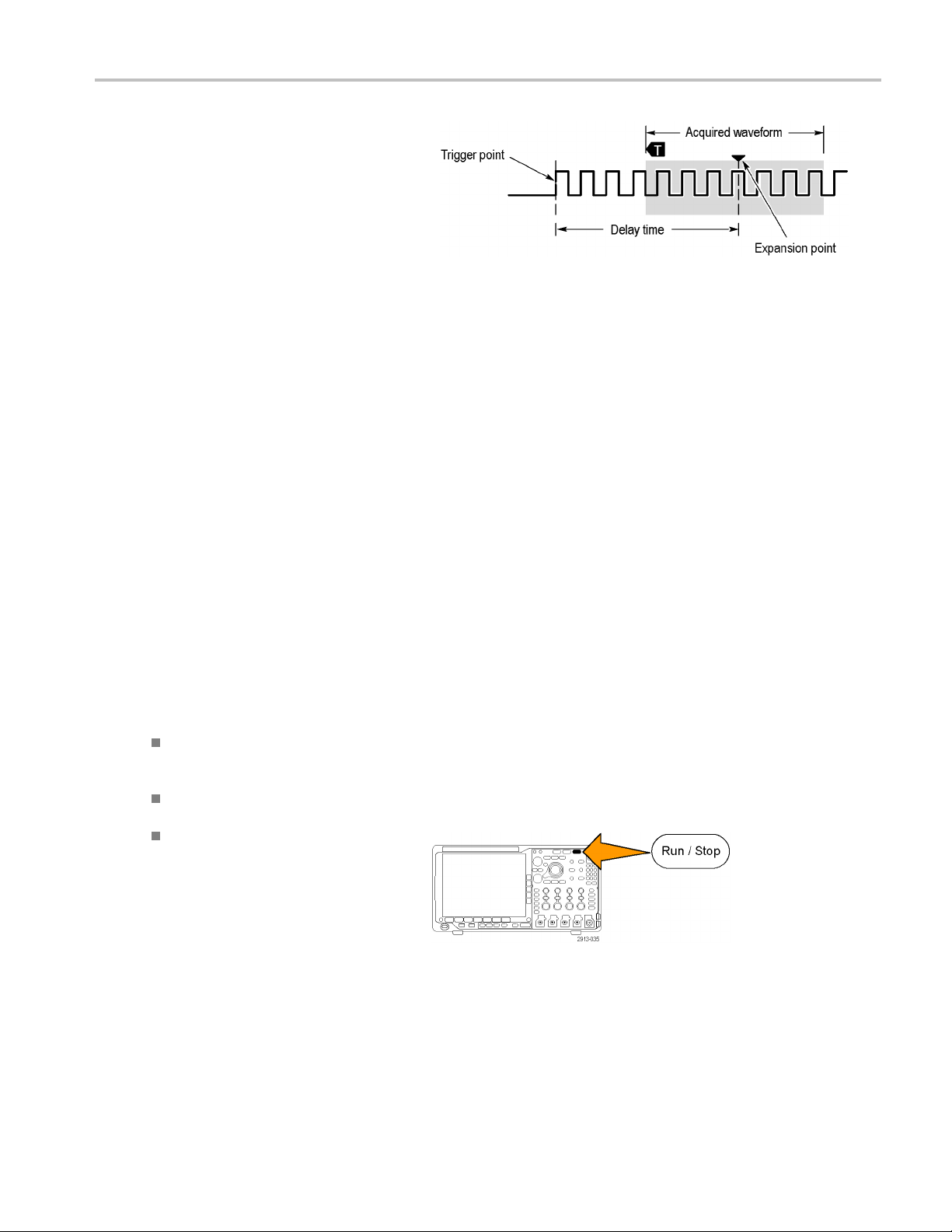
Acquire the Sign
al
7. Push the lower-
On when you want to delay the acquisition
relative to the trigger event.
With Delay set to On, turn the Horizontal Position knob counterclockwise to increase the delay. The trigger point will move
to the left and ultimately outside of the acquired waveform. Then you can adjust the Horizontal Scale knob to acquire more
detail around the area of interest at the center of the screen.
When this delay is on, the trigger point separates from the horizontal expansion point. The horizontal expansion point
stays at the center of the screen. The trigger point can move off the screen. When this happens, the trigger marker turns
to point in the direction of the trigger point.
Use the delay feature when you want to acquire waveform detail that is separated from the trigger event by a significant
interval of time. For example, you can trigger on a sync pulse that occurs once every 10 ms and then look at high-speed
signal characteristics that occur 6 ms after the sync pulse.
When the delay feature is set to Off, the expansion point is tied to the trigger point so that scale changes are centered
around the trigger point.
Using Roll Mode
bezel Delay button to select
Roll mode gives a display similar to a strip chart recorder fo r low-frequency signals. Roll mode lets you see acquired data
ithout waiting for the acquisition of a complete waveform record.
points w
de is enabled when the trigger mode is auto and the horizontal scale is set to 40 ms/div or slower.
Roll mo
Quick Tips
Switching to Envelope or Average acquisition mode, using digital channels, using math waveforms, turning on a bus,
tching to Normal trigger will disable Roll mode.
or swi
mode is disabled when you set the horizontal scale to 20 ms per division or faster.
Roll
Run/Stop to halt Roll mode.
Push
MDO4000 Series Oscilloscopes User Manual 59
Page 79

Acquire the Sign
al
Setting Up a Serial or Parallel Bus
Your oscilloscope can decode and trigger on signal events or conditions that occur on:
Bus type With this hardware
Audio (I2S, Left Justified (LJ), Right
Justified (RJ), and TDM)
CAN and LIN DPO4AUTO or DPO4AUTOMAX application module
Ethernet
FlexRay
I2C and SPI DPO4EMBD application module
MIL-STD-1553 DPO4AERO application module
Parallel
RS-232, RS-422, RS-485, and
UART
USB 2.0 DPO4USB application module
(See page 15, Application Module Free Trial.)
DPO4AUDIO application m odule
DPO4ENET application module
DPO4AUTOMAX application module
MDO4000 Series oscilloscope
DPO4COMP application module
Using Buses in Two Steps
To quickly use serial bus triggering:
1. Push B1, B2, B3,orB4 and enter
parameters of the bus on which to trigger.
You can separately assign a different bus to
each of the B1, B2, B3, and B4 buttons.
60 MDO4000 Series Oscilloscopes User Manual
Page 80

Acquire the Sign
al
2. Push Trigger Me
nu and enter trigger
parameters. (See page 83, Choosing a
Trigger Type.)
You can displa
y bus information without
triggering on the bus signal.
SettingUpBu
s Parameters
NOTE. For most bus sources, you may use any combination of channels 1 through 4, and D15 through D0. With some
buses, you may also use Ref 1 through 4 and Math as sources for protocol decode.
To trig g e r
on serial or parallel bus conditions, refer to Triggering on Buses. (See page 86, Triggering on Buses.)
To set up bus parameters:
1. Push B1, B2
, B3,orB4 to bring up the
lower-bezel bus menu.
2. Push Bus. Turn multipurpose knob a to
scroll through the list of bus types and select
the desired bus: Parallel, I
2
C, SPI, RS-232,
CAN, LIN, FlexRay, Audio, USB, Ethernet, or
MIL-STD-1553.
The actual menu items shown will depend on
your model oscilloscope and the application
modules installed.
3. Push Define Inputs. The choices depend
on the selected bus.
Bus B1
Parall
Define
Inputs
el
Thresholds B1 Label
Parallel
Bus
Display
Event
Table
MDO4000 Series Oscilloscopes User Manual 61
Page 81

Acquire the Sign
al
Use the side-bezel buttons to define
parameters for the inputs, such as specific
signals to an a
nalog or digital channel.
If you select Parallel, push the side-bezel
button to ena
Push the side
ble or disable Clocked Data.
-bezel button to select the
Clock Edge on which to clock data: rising
edge, falling edge, or both edges.
Turn multip
urpose knob a to select the
Number of Data Bits in the parallel bus.
Turn multipurpose knob a to select the
desired bi
ttodefine.
Turn multipurpose knob b to select the
desired analog or digital channel as the
source fo
r the bit.
4. Push Thresholds.
You can set the threshold for all channels in
the parallel or serial bus from a list of preset
. The preset values vary, depending
values
on the bus type.
Define
Inputs
Clocked
Data
No
Yes |
Clock
Edge
Number of
Data Bits
(a) 16
Define Bits
(a) Bit 15
(b) D15
Bus B1
Parallel
Define
Inputs
Thresholds B1 Label
Parallel
Bus
Display
Event
Tab l e
Alternatively, you can set the threshold to
fic value for the signals that make
a speci
up the parallel or serial bus. To do so,
push the Select side-bezel button and turn
purpose knob a to select a B it or a
multi
Channel number (Signal name).
Then, turn multipurpose knob b to define the
voltage level above which the oscilloscope
treats the signal as a logic high and below
which as a logic low.
NOTE. Some buses use two thresholds per
channel.
62 MDO4000 Series Oscilloscopes User Manual
Page 82

Acquire the Sign
al
5. Optionally, push B1 Label to edit the label for
the bus. (See page 51, Labeling Channels
and Buses.)
6. Push Bus Display and use the side-bezel
menu to defin
e how to display the parallel or
serial bus.
Depending on the bus, use the side-bezel
menu or the
knobs to set the number format.
7. Push Event Table and select On to display a
us packets with timestamps.
list of b
Bus B1
Parallel
Bus
Bus and
Wave-
forms
Hex
Binary
ASCII
Event
Tab l e
On |Off
Save
Event
Tab l e
Define
Inputs
Thresholds B1 Label
Parallel
Bus
Display
Event
Table
ocked parallel bus, the table lists the
For a cl
value of the bus at each clock edge. For
an unclocked parallel bus, the table lists the
of the bus whenever any one of its bits
value
changes.
The Event Table lists bytes, words, or
ts, depending on the bus type.
packe
8. Push
Save Event Table to save the event
table data in a .csv (spreadsheet) format on
the currently selected storage device.
MDO4000 Series Oscilloscopes User Manual 63
Page 83

Acquire the Sign
al
This example of an Event Table is from an
RS-232 bus.
RS-232 event t
ables display one line for each
7- or 8-bit byte when Packets are set to Off.
RS-232 event tables display one line for each
packet when P
ackets are set to On.
Other buses display one word, frame, or
packet per row, depending on the bus type.
64 MDO4000 Series Oscilloscopes User Manual
Page 84

Acquire the Sign
al
9. Push B1, B2, B3,
or B4 and turn multipurpose
knob a to move the bus display up or down
on the screen.
I2CBus
To acquire data from an I2C bus, you need to also set up these items:
1. If you select I2C, push Define Inputs and
the appropriate side-bezel menu choices.
Bus B1
I2C
Define
Inputs
Thresholds Include
R/W in
Address
No
You can assign the predefined SCLK Input
or SDA Input to the channel connected to
the signal.
2. Push Include R/W in Addr ess and then
push the desired side-bezel button.
This control determines how the oscilloscope
shows the I
2
C addresses in bus decode
traces, cursor readouts, Event Table listings,
and trigger settings.
If you select Yes, the oscilloscope displays 7-bit addresses as eight bits, where the eighth bit (LSB) is the R/W bit. It
displays 10-bit addresses as 11 bits w here the third bit is the R/W bit.
B1 Label
I2C
Bus
Display
Event
Tab l e
If you select No, the oscilloscope displays 7-bit addresses as seven bits, and 10-bit addresses as ten bits.
2
In the physical layer of the I
C protocol, 10 bit I2C addresses are preceded by the five bit code, 11110. The oscilloscope
does not include these five bits in address readouts.
SPI Bus
To acquire data from an SPI bus, you need to also set up these items:
1. If you
selected SPI, push Define Inputs and
the appropriate side-bezel menu choices.
an set the Framing to SS (Slave
You c
Select) or to Idle Time.
You can assign the predefined SCLK, SS,
,orMISO signals to any channel.
MOSI
2. Push Configu re and the desired side-bezel
u choices.
men
Bus B1
SPI
Define
Inputs
Thresholds
Configure
B1 Label
SPI
Bus
Displ
Event
ay
Tab l e
MDO4000 Series Oscilloscopes User Manual 65
Page 85

Acquire the Sign
al
3. Push SCLK to set the edge of the signal to
match the SPI bus being acquired.
4. Set the level of the SS, MOSI, and MISO
signals to match the SPI bus.
Active High m
eans that a signal is considered
active when the signal is greater than the
threshold value.
Active Low me
ans that the signal is
considered active when the signal is lower
than the threshold value.
5. Use multip
urpose knob a to set the number
of bits of the SPI Word Size.
6. Push eithe
r side bezel button to set the bit
order of the SPI bus.
SCLK
SS
Active
High
Active Low
MOSI
Active
High
Active Low
MISO
Active
High
Active Low
-more10f2
Word Size
(a) 8 bits
Bit Order
MS First
Bit Order
LS First
RS-232 Bus
To acquire data from a RS-232 bus, you need to also set up these items:
1. If you selected RS-232, push Configure and
the desired side-bezel menu choices.
Use the side-bezel menu to con figure the
bus. Use Normal polarity for RS-232 signals
and Inverted polarity for RS-422, RS-485,
and UART buses.
Bus B1
RS-23
Define
Inputs
2
Thresholds
Configure
8-N
9600-
B1 Label
RS-232
Bus
Display
Event
Tabl e
66 MDO4000 Series Oscilloscopes User Manual
Page 86
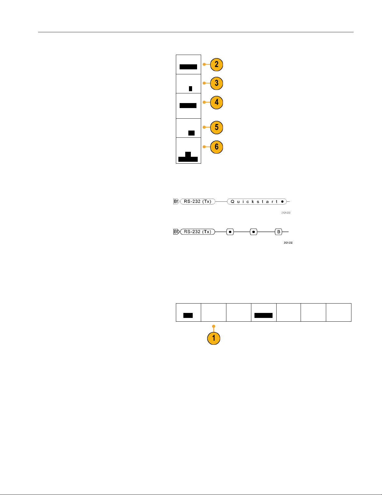
Acquire the Sign
al
2. Push Bit Rate,
and turn multipurpose knob a
to select the appropriate bit rate.
3. Push Data Bits
and select the number to
match the bus.
4. Push Parity a
nd turn multipurpose knob a to
match the polarity used by the bus as None,
Odd, or Even.
5. Push Packets and select On or Off.
6. Turn multip
urpose knob a to select an
end-of-packet character.
RS-232 decoding displays a stream of bytes.
You can organize the stream into packets
with an end
If you de fi n
-of-packet character
ed an end-of-packet character
to use for RS-232 decoding, the stream of
bytes will be displayed as packets.
When decoding an RS-232 bus in ASCII
mode, a l
arge dot indicates that the value
represents a character outside the printable
ASCII range.
Bit Rate
9600 bps
Data Bits
7|
8
Parity
(a) None
Packets
On|
Off
End of
Packet
0A
(Linefeed)
CAN Bus
To acquire data from a CAN bus, you need to also set up these items:
1. If you selected CAN, push Define Inputs and
the appropriate side-bezel menu choices.
Bus B1
CAN
Define
Inputs
Thresholds Bit Rate
500 Kb
B1 Label
CAN
ps
Bus
Display
Event
Tab l e
MDO4000 Series Oscilloscopes User Manual 67
Page 87

Acquire the Sign
al
2. Turn multipur
pose knob a to select the
channel connected to the CAN bus source.
3. Turn multipur
pose knob a to select the type
of CAN signal: CAN_H, CAN_L, Rx, Tx, or
Differential.
4. Turn multipurpose knob a to set the Sample
Point from 5% to 95% of the position within
the bit peri
od or the unit interval.
5. Push Bit Rate and turn multipurpose knob a
to select from the list of predefined bit rates.
Alternati
vely, you can set the bit rate to a
CAN Input
(a) 1
Signal
Type
CAN_H
Sample
Point
50%
Bus B1
CAN
Define
Inputs
specific value. To do so, select Custom, and
then turn multipurpose knob b to set the bit
rate from
10,000 to 1,000,000.
LIN Bus
To acquire data from a LIN bus, you need to also set up these items:
1. If you selected LIN, push Define Inputs and
the appropriate side-bezel menu choices.
Bus B1
LIN
Define
Inputs
Thresholds Bit Rate
500 Kbps
Thresholds
Configure
B1 Label
CAN
B1 Label
LIN
Bus
Display
Bus
Display
Event
Tabl e
Event
Tab l e
2. Turn multipurpose knob a to select the
channel connected to the LIN bus source.
3. Turn multipurpose knob a to set the Sample
Point from 5% to 95% of the position within
the bit period or the unit interval.
4. Select the Polarity to match the LIN bus
being acquired.
LIN Input
(a) 1
Sample
Point
50%
Polarity
Normal
(High=1)
Polarity
Inverted
(High=0)
68 MDO4000 Series Oscilloscopes User Manual
Page 88

Acquire the Sign
al
5. Push Configure and the appropriate
side-bezel menu choices.
6. Push Bit Rate, and turn multipurpose knob a
to select from the list of predefined bit rates.
Alternativ
ely, you can set the bit rate to a
specific value. To do so, select Custom , and
then turn multipurpose knob b to set the bit
rate from 8
00 bps to 100,000 bps.
7. Push LIN Standard, and turn multipurpose
knob a to s
elect the appropriate standard.
8. Push Include Parity Bits with Id to select
whether or not to include parity bits.
Audio Bu
s
Bus B1
LIN
Bit Rate
(a)
19.2K bps
LIN
Standard
v1.x
Include
Parity Bits
with Id
On|
Off
Define
Inputs
Thresholds
Configure
B1 Label
LIN
Bus
Display
Event
Table
To acquire data from an Audio bus, you need to also set up these items:
1. If you selected Audio, push Define Inputs
and the desired side-bezel menu choices.
Bus B1
Audio
Define
Inputs
Thresholds
Configure
B1 Label
RS-232
Bus
Display
Event
Tab l e
MDO4000 Series Oscilloscopes User Manual 69
Page 89

Acquire the Sign
al
2. Push Ty pe, and
turn multipurpose knob
a to select the type of audio bus data
configuration on which to trigger.
3. Select I2S to trigger on the standard Inter-IC
Sound, or Integrated Interchip Sound,
electrical s
erial bus interface standard stereo
format.
4. Select Left
Justified to trigger on an I2S
stream where there is no bit clock delay and
the data starts right on the edge of the word
select clo
ck.
5. Select Right Justified to trigger on an I2S
stream wh
ere the data lines up with the right
edge of the word select clock.
6. Select TD
M to trigger on time-division
multiplexing.
7. Push Co
nfigure, and the appropriate
side-menu buttons to further set up I2S
triggering.
USB Bus
Audio Bus
Type
I2S
Left
Justified
(LJ)
Right
Justified
(RJ)
TDM
To acquire data from a USB bus, you need to also set up these items:
1. If you selected USB, push Define Inputs to
set the USB bus speed and probe type.
Bus B1
USB
Define
Inputs
Full Speed
Thresholds B1 Label
USB
Bus
Display
Event
Tabl e
70 MDO4000 Series Oscilloscopes User Manual
Page 90
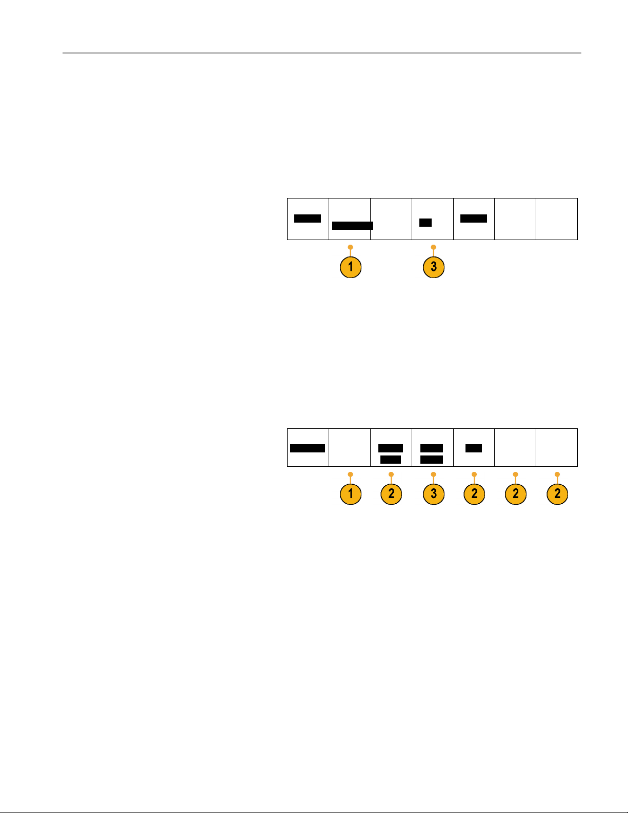
Acquire the Sign
al
2. The Thresholds
, Label, Bus Display, and
Event Table menus operate similarly to the
other serial buses.
Ethernet
To acquire data from an Ethernet bus, you need to also set up these items:
1. If you selected Ethernet, push Define
Inputs and the desired side-bezel menu
choices.
2. The Thresholds, Bus Display, and Event
Table menus operate similarly to the other
serial buses.
3. Push IPv4 to decide whether or not to
decode and trigger on Internet Protocol
version 4 signals.
Bus (B1)
Ethernet
Define
Inputs
100BASE-TX
Thresholds IPv4
Yes |No
(B1) Label
Ethernet
Bus
Display
Event
Table
MIL-STD 1553
To acquire data from a MIL-STD 1553 bus, you
need to also set up these items:
1. Push Define Inputs and use multipurpose
knob a to select the desired side-bezel menu
choices. S elect the polarity desired to match
the MIL-STD-1553 bus being acquired.
Bus B1
MIL – 1553
Define
Inputs
Thresholds
800 mV
0.00 V
RT
12.0μS
4.00μS
B1 Label
1553
Bus
Display
Event
Table
MDO4000 Series Oscilloscopes User Manual 71
Page 91

Acquire the Sign
al
2. The Thresholds
Event Table menu items operate similarly to
how they work on other serial bus menus.
3. Push RT if you wish to change the Response
Time (RT) maximum and minimum default
values.
Physical La
Oscilloscope waveform traces from analog channels 1 to 4, di gital channels D15 to D0, Math waveforms, and the traces you
see when you choose to display a bus always show the physical layer bus activity. In the physical layer display, bits that were
transmitted earlier are to the left, and bits that were transmitted later are to the right.
I2C, and CAN buses transmit the MSB (most significant bit) first
SPI buses do not specify a bit order
RS-232 and LIN buses transmit the LSB (least significant bit) first
NOTE. The oscilloscope displays the decode traces and event tables for all buses with the MSB on the left and LSB
on the right.
For example, an RS-232 signal (after the start bit) might be high, high, high, low, high, low, low, and high. Since the RS-232
protocol uses high for zero and low for one, this value would be 0001 0110.
, Label, Bus Display,and
yer Bus Activity
Since the decode displays the MSB first, the oscilloscope reverses the order of the bits and displays 0110 1000. If the bus
display is set to hex, the value displays as 68. If the bus display is set to ASCII, the value displays as h.
72 MDO4000 Series Oscilloscopes User Manual
Page 92

Setting Up Digital Channels
Use front-panel buttons and knobs to set up your instrument to acquire signals using the digital channels.
Acquire the Sign
al
1. Connect the P6
616 16-channel logic probe
to the input signal source.
2. Connect the ground lead or leads to the
circuit ground.
You can connect a separate lead for each
channel or a common ground lead for each
group of 8 wires.
3. If needed, connect the appropriate grabber
for each probe to the probe tip.
4. Connect each probe to the desired circuit
test point.
5. Push the D15 - D 0 front panel button to
display the menu.
6. Push the lower-bezel D15 - D0 button to
access the D15 - D0 On or Off menu.
D15–D0
On/Off
Thresholds Edit Labels MagniVu
On |
Off
Height
S |ML
MDO4000 Series Oscilloscopes User Manual 73
Page 93

Acquire the Sign
al
7. Turn multipurp
the list of digital channels. Turn multipurpose
knob b to position the selected channel.
As you positio
on the display, the oscilloscope groups the
channels, and adds the group to the pop-up
list. You can
move all the channels in the group instead of
individual channels.
8. Push the low
You can assign a different threshold value
to each channel.
9. Push the lo
and create the label. You can create labels
through the front panel or with an optional
USB keyboa
Channels and Buses.)
10. Push the lower-bezel MagniVu button to
increase
When and Why to Turn O n MagniVu.)
11. Push the lower-bezel Heig ht button
repeate
need to do this once to set the height for all
of the digital channels.
ose knob a to scroll through
n channels close to each other
select the group from the list to
er-bezel Thresholds button.
wer-bezel Edit Labels button
rd. (See page 51, Labeling
the timing resolution. (See page 75,
dly to set the signal height. You only
Quick Tip
Use the zoom feature to see multiple cycles of the signal in the upper part, and a single cycle in the lower part of the
display. (See page 144, Using Wave Inspector to Manage Long Record Length Waveforms.)
When setting up the logic probe, the first set of eight leads (pins 7 to 0) on the logic probe are marked GROUP 1 on the
lead box. The second set (pins 15 to 8) is marked GROUP 2.
Theleadforthefi rst channel in each group is colored blue for easy identification while you connect the logic probe to the
device under test. The other leads are gray.
Digital channels store a high or low state for each sample. The threshold that separates high from low can be set
separately for each channel.
74 MDO4000 Series Oscilloscopes User Manual
Page 94

When and Why to Turn On MagniVu
Te ktronix MagniVu acquisition technology allows you to have higher timing resolution so that you can more accurately
determine edge placement and make more precise timing measurements on digital edges. Using MagniVu, you can see
up to 32 times more detail than you can using normal digital channel sampling.
The MagniVu record is acquired in parallel to the main digita l acquisition and is available at any time, running or stopped.
MagniVu provides an ultra high resolution view of your data sampled at a maximum resolution of 60.6 ps for 10,000 points
centered around the trigger.
NOTE. MagniVu centers itself around the trigger point. If you turn MagniVu on while using a large record length and you are
looking somewhere other than the trigger point, then the digital signal may be off screen. In most of these cases, you can find
the digital record by looking for the digital signal in the upper overview and panning accordingly.
NOTE. You should turn on MagniVu when light gray shading is displayed to indicate the uncertainty of the edge position. If
the shading is not displayed, you do not need to use MagniVu. (See page 108, Viewing Digital Channels.)
Using M agniVu
1. Push D15 – D0.
Acquire the Sign
al
2. Push MagniVu and select On.
D15 – D0
On/Off
Quick Tips
u think you need more timing resolution, turn on MagniVu to increase the resolution.
If yo
iVu is always acquired. If the oscilloscope is in a stopped state, you can turn on MagniVu and still get the resolution
Magn
without taking another acquisition.
The serial bus features do not use data acquired in MagniVu mode.
Thresholds Label MagniVu
On |
Off
Height
S |ML
MDO4000 Series Oscilloscopes User Manual 75
Page 95
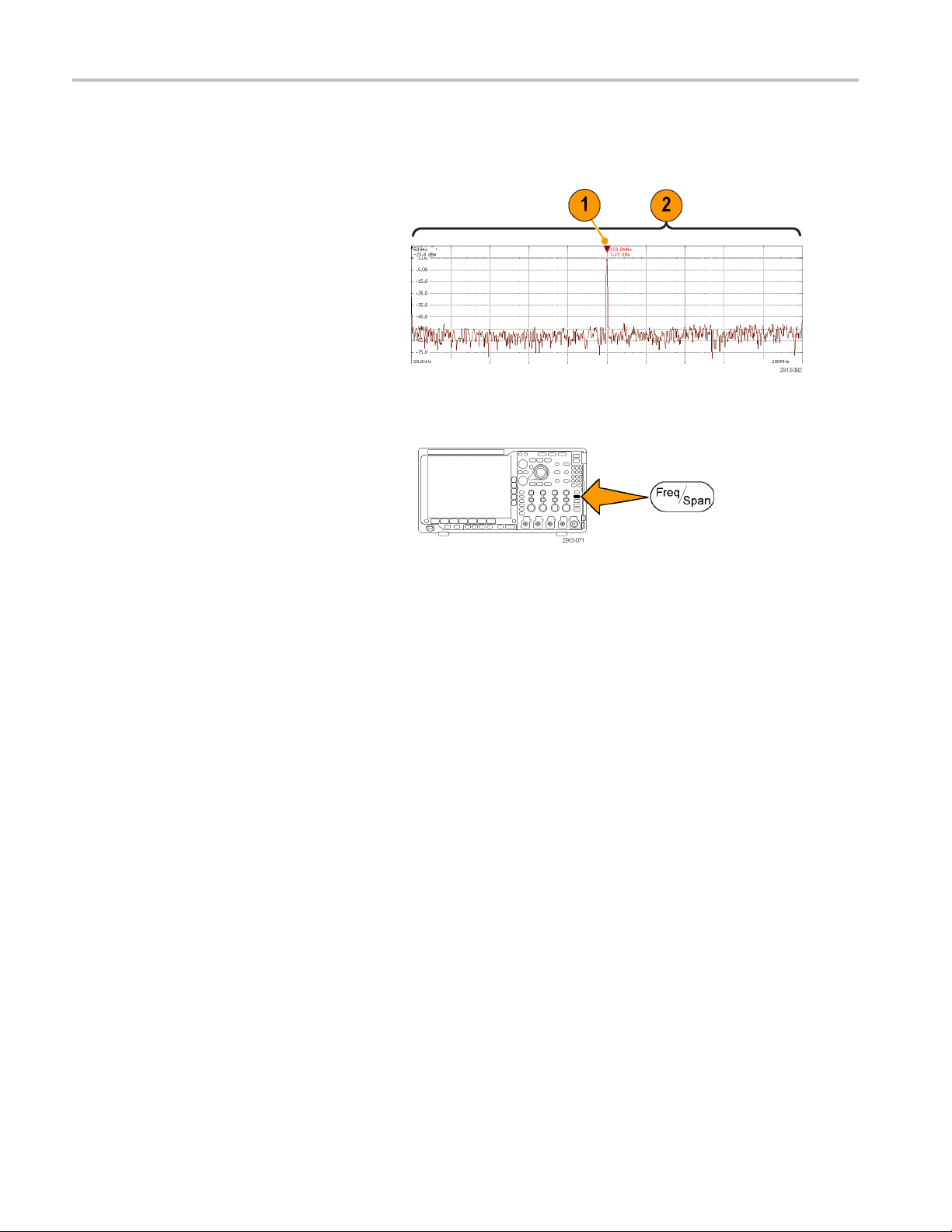
Acquire the Sign
al
Setting Up the RF Inputs
Frequency and Span Parameters
1. The center frequency is a precise
frequency at the center of the display.
In many applications, it is a carrier
frequency.
2. The span is the range of frequencies
you can observe around the center
frequency.
To d efine the center frequency and the span:
1. Push the front-panel Freq/Span button.
76 MDO4000 Series Oscilloscopes User Manual
Page 96

2. Push Center Fr
equency from the side
menu and use either the multipurpose knob
a or the oscilloscope keypad to enter the
desired cent
er frequency. If you use the
keypad, you can also use the resulting side
menu choices to enter units.
3. Push Span and use either multipurpose
knob b or the keypad to enter the desired
span. If you
use the keypad, you can also
use the resulting side menu choices to enter
units.
4. Push Start to set the lowest frequency to
capture.
5. Push Stop to set the highest frequency to
capture.
6. Push To Cent er to move the frequency
identified by the reference m arker to the
center frequency.
Frequency
& Span
Center
Frequency
(a)
2.24 GHz
Span
(a)
3.00 GHz
Start
7.36 MHz
Stop
3.74 GHz
To Center
Acquire the Sign
al
Reference Level
1. Push A
mpl to bring up the side menu for
adjusting RF amplitude settings.
MDO4000 Series Oscilloscopes User Manual 77
Page 97

Acquire the Sign
2. Push Ref Level and rotate multipurpose
3. Push Vertica
4. Push Vertical Units and rotate multipurpose
5. Push Auto Level to direct the oscilloscope
al
knob a to set th
e approximate maximum
power level, as shown by the baseline
indicator at the top of the frequency graticule.
l and rotate multipurpose knob
a to adjust the vertical position. You will
move the baseline indicator up or down.
This is usef
ul if you want to move signals
onto the visible display.
Rotate multipurpose knob b to adjust the
vertical s
cale.
knob a to define the vertical units of measure
for the fr
equency domain. Choices are:
dBm, dBμW, dBmV, dBμV, dBmA, and
dBμA. This is useful if your application
requires
a different unit of measurement
than that being currently displayed.
to autom
atically calculate and set the
reference level for you.
Amplitude
Ref Level
(a)
-25.0 dBm
Vertical
420 mdiv
20.0 dB/div
Vertical
Units
dBm
Auto Level
Resolution Bandwidth
The resolution bandwidth (RBW) determines the level to which the oscilloscope can resolve individual frequencies in
the frequency domain. For example, i f the test signal contains two carriers separated by 1 kHz, you will not be able to
discriminate between them unless the RBW is less than 1 kHz.
The views below both show the same signal. The difference between them is their RBW.
Lower (narrower) RBWs take longer to process,
but have finer frequency resolution and a lower
noise floor.
Higher (wider) RBWs take less time to process, but have less frequency re solution
and a higher noise floor.
78 MDO4000 Series Oscilloscopes User Manual
Page 98

Acquire the Sign
al
1. Push BW to bring
up the resolution
bandwidth side menu. This allows you to set
the smallest frequency difference that the
instrument ca
n discern in the frequency axis.
2. Push RBW Mode to select either Auto or
Manual.
Auto sets the resolution bandwidth
automatically as you change the span. The
default behavior is RBW = Span/1000.
Manual allows you to set your own
resolution bandwidth.
3. To manually adjust the RBW, push RBW
and turn multipurpose knob a.
4. Push Span : RBW and turn multipurpose
knob a to set the span/RBW ratio.
ThisratioisusedwhentheRBW Mode is
set to Auto. The default is 1000:1 but you
can set it to other values in a 1-2-5 sequence
(e.g. 1000, 20000, 50000).
5. Push Window and turn multipurpose knob a
to choose which FFT window type to use.
The choices are: Kaiser, Rectangular,
Hamming, Hanning, Blackman-Harris, or
Flat-Top.
Bandwidth
RBW
Mode
Auto
Manual
RBW
(a)
600 kHz
(Auto)
Span :
RBW
1000 : 1
Window
Kaiser
MDO4000 Series Oscilloscopes User Manual 79
Page 99

Trigger Setup
Trigger Setup
This section contains concepts and procedures for setting up the oscilloscope to trigger on your signal.
Triggering Concepts
Trigger Event
The trigger event establishes the time-reference point in the waveform record. All waveform record data is located in time
with respect to that point. The instrument continuously acquires and retains enough sample points to fill the pretrigger portion
of the waveform record. That is the part of the waveform that is displayed before, or to the left of, the triggering event on
screen. When a trigger event occurs, the instrument starts acquiring samples to build the posttrigger portion of the waveform
record, that is, the part displayed after or to the right of the trigger event. After a trigger is recognized, the instrument will not
accept another trigger until the acquisition is complete and the holdoff time has expired.
Untrigg
ered display
Trigger
ed display
Trigger Modes
The trigger mode determines how the instrument behaves in the absence of a trigger event:
Normal trigger mode enables the instrument to acquire a w aveform only when it is triggered. If no trigger occurs, the last
waveform record acquired remains on the display. If no last waveform exists, no waveform is displayed.
Auto trigger mode enables the instrument to acquire a waveform even if a trigger does not occur. Auto mode uses a
timer that starts when the acquisition is started, and the pretrigger information is obtained. If a trigger event is not
detected before the timer times out, the instrument forces a trigger. The length of time it waits for a trigger event
depends on the time base setting.
Auto mode, when forcing triggers in the absence of valid triggering events, does not synchronize the waveform on the
display. The waveform will appear to roll across the screen. If valid triggers occur, the display will become stable.
You can also force the instrument to trigger by pushing the front-panel Force Trig button.
80 MDO4000 Series Oscilloscopes User Manual
Page 100

Trigger Holdoff
Trigger Setup
Adjust holdof
the instrument is triggering on undesired
trigger events.
Trigger holdo
since the oscilloscope does not recognize
new triggers during the holdoff time. When
the instrume
disables the trigger system until acquisition
is complete. In addition, the trigger system
remains dis
that follows each acquisition.
f to obtain stable triggering when
ff can help stabilize triggering,
nt recognizes a trigger event, it
abled during the holdoff period
Trigger Coupling
Trigger co
signal is passed to the trigger circuit. Edge
and Sequence triggering can use all available
coupling
Rejection, High Frequency Rejection, and
Noise Rejection. All other trigger types use
DC coupl
upling determines what part of the
types: DC, AC, Low Frequency
ing only.
Holdoffs
Horizontal Position
When Delay Mode is on, use horizontal
position to acquire waveform detail in a
that is separated from the trigger
region
location by a significant interval of time.
MDO4000 Series Oscilloscopes User Manual 81
 Loading...