

Page 1

Test Equipment Depot - 800.517.8431 - 99 Washington Street Melrose, MA 02176 - TestEquipmentDepot.com
MDO4000C Series
Mixed Domain Oscilloscope
User Manual
*P077116700*
077-1167-00
Page 2

Page 3

MDO4000C Series
Mixed Domain Oscilloscope
User Manual
Warning
The servicing instructions are for use by qualified personnel only. To avoid
personal injury, do not perform any servicing unless you are qualified to do
so. Refer to all safety summaries prior to performing service.
Supports Firmware V1.02 and above
Page 4

Copyright © Tektronix. All rights reserved. Licensed software products are owned by Tektronix or its subsidiaries or suppliers, and are
protected by national copyright laws and international treaty provisions. Tektronix products are covered by U.S. and foreign patents, issued
and pending. Information in this publication supersedes that in all previously published material. Specifications and price change privileges
reserved.
TEKTRONIX and TEK are registered trademarks of Tektronix, Inc.
Page 5

Table of Contents
Important safety information ................................................................................................................................ ix
General safety summary ............................................................................................................................... ix
Service safety summary ................................................................................................................................ xi
Terms in the manual
Terms on the product .................................................................................................................................... xii
Symbols on the product ................................................................................................................................ xii
Compliance Information ..................................................................................................................................... xiii
EMC compliance .......................................................................................................................................... xiii
Safety compliance ....................................................................................................................................... xiv
Environmental compliance ........................................................................................................................... xvi
Preface ............................................................................................................................................................. xvii
Key features ................................................................................................................................................ xvii
Conventions used in this manual ................................................................................................................ xvii
Warranty ..................................................................................................................................................... xvii
Installation
..................................................................................................................................... xii
Before installation ........................................................................................................................................... 1
Operating positions ........................................................................................................................................ 7
Connecting probes ......................................................................................................................................... 8
Securing the oscilloscope ............................................................................................................................ 10
Power-On ..................................................................................................................................................... 10
Powering off the oscilloscope ....................................................................................................................... 11
Functional check .......................................................................................................................................... 12
Compensating a TPP0500B or TPP1000 passive voltage probe ................................................................ 14
Compensating a non-TPP0500B or non-TPP1000 passive voltage probe .................................................. 16
Application module free trial ......................................................................................................................... 17
Installing an application module ................................................................................................................... 17
Upgrading bandwidth ................................................................................................................................... 18
Changing the language of the user interface or keyboard ........................................................................... 19
Changing the date and time ......................................................................................................................... 20
Signal path compensation for time and frequency domains ........................................................................ 21
Upgrading firmware ...................................................................................................................................... 23
Connecting your oscilloscope to a computer ............................................................................................... 25
Using VISA ............................................................................................................................................. 25
Using e*Scope ........................................................................................................................................ 25
Using the LXI web page and e*Scope .................................................................................................... 26
MDO4000C Series Oscilloscope User Manual i
Page 6

Table of Contents
Using a socket server ............................................................................................................................. 26
Connecting a USB keyboard to your oscilloscope
....................................................................................... 28
Get acquainted with the instrument
Front-panel menus, controls, and connectors .............................................................................................. 29
Front panel menus and controls ................................................................................................................... 30
Using the menu system .......................................................................................................................... 30
Using the menu buttons ......................................................................................................................... 31
Below the display buttons ....................................................................................................................... 32
Using spectral analysis controls ............................................................................................................. 34
Using other controls ............................................................................................................................... 34
Identifying items in the time domain display ........................................................................................... 37
Identifying items in the frequency domain display .................................................................................. 41
Identifying items in the arbitrary/function generator display ................................................................... 42
Identifying Items in the digital voltmeter display ..................................................................................... 42
Rear-Panel Connectors ................................................................................................................................ 43
Acquire the signal
Setting up analog channels .......................................................................................................................... 45
Labeling channels and buses ....................................................................................................................... 47
Using the default setup ................................................................................................................................ 48
Using autoset ............................................................................................................................................... 49
Acquisition concepts .................................................................................................................................... 50
Using FastAcq .............................................................................................................................................. 52
How the analog acquisition modes work ...................................................................................................... 54
Changing the Acquisition Mode, Record Length, and Delay Time ............................................................... 55
Using Roll Mode ........................................................................................................................................... 57
Act on Event ................................................................................................................................................. 57
Setting up a serial or parallel bus ................................................................................................................. 58
Using buses in two steps ........................................................................................................................ 58
Setting up bus parameters ..................................................................................................................... 59
I2C bus ................................................................................................................................................... 62
SPI bus ................................................................................................................................................... 62
RS 232 bus ............................................................................................................................................. 63
CAN bus ................................................................................................................................................. 64
LIN bus ................................................................................................................................................... 65
FlexRay bus ........................................................................................................................................... 66
Ethernet .................................................................................................................................................. 67
ii MDO4000C Series Oscilloscope User Manual
Page 7

Table of Contents
Audio bus ............................................................................................................................................... 67
USB bus ................................................................................................................................................. 68
MIL STD 1553 ........................................................................................................................................ 68
Physical layer bus activity ...................................................................................................................... 68
Labeling channels and buses ................................................................................................................. 69
Setting up digital channels ........................................................................................................................... 70
When and why to turn on MagniVu .............................................................................................................. 72
Using MagniVu ............................................................................................................................................. 73
Setting up the RF inputs
Frequency and span parameters ........................................................................................................... 73
Reference Level ..................................................................................................................................... 74
Resolution bandwidth ............................................................................................................................. 74
............................................................................................................................... 73
Trigger setup
Triggering concepts ...................................................................................................................................... 77
Trigger event .......................................................................................................................................... 77
Trigger modes ........................................................................................................................................ 78
Trigger holdoff ........................................................................................................................................ 78
Trigger coupling ...................................................................................................................................... 78
Horizontal Position ................................................................................................................................. 78
Slope and level ....................................................................................................................................... 79
Choosing a trigger type ................................................................................................................................ 80
Selecting triggers ......................................................................................................................................... 81
Triggering on buses ..................................................................................................................................... 84
Parallel bus trigger ....................................................................................................................................... 84
I2C bus trigger .............................................................................................................................................. 84
SPI bus trigger ............................................................................................................................................. 85
RS-232 bus trigger ....................................................................................................................................... 85
CAN bus trigger ............................................................................................................................................ 85
LIN bus trigger .............................................................................................................................................. 85
FlexRay bus trigger ...................................................................................................................................... 86
Audio bus trigger .......................................................................................................................................... 86
USB bus trigger ............................................................................................................................................ 86
Ethernet bus trigger ...................................................................................................................................... 86
MIL-STD-1553 bus trigger ............................................................................................................................ 86
Data value matching .................................................................................................................................... 87
Parallel bus trigger data matching ................................................................................................................ 87
Checking trigger settings .............................................................................................................................. 88
MDO4000C Series Oscilloscope User Manual iii
Page 8

Table of Contents
Using sequence trigger (A (main) and B (delayed)) ..................................................................................... 88
B trigger after delay time ........................................................................................................................ 89
Trigger on B events ................................................................................................................................ 89
Starting and stopping an acquisition ............................................................................................................ 90
Display waveform or trace data
Adding and removing a waveform
Setting the display style and persistence ..................................................................................................... 91
Setting the graticule style ....................................................................................................................... 93
Setting the LCD backlight brightness and dimming settings .................................................................. 94
Setting waveform intensity ........................................................................................................................... 95
Scaling and positioning a waveform ............................................................................................................. 96
Setting input parameters .............................................................................................................................. 97
Positioning and labeling bus signals ............................................................................................................ 99
Positioning, scaling, and grouping digital channels .................................................................................... 101
Viewing digital channels ............................................................................................................................. 102
Annotating the screen ................................................................................................................................ 103
Viewing the trigger frequency ..................................................................................................................... 104
Displaying the Frequency domain menu .................................................................................................... 105
Trace types ........................................................................................................................................... 105
Detection types ..................................................................................................................................... 107
Spectrogram display ............................................................................................................................. 108
................................................................................................................ 91
Analyze waveform or trace data
Using markers in the frequency domain ..................................................................................................... 109
Automatic peak markers ....................................................................................................................... 109
Manual markers .................................................................................................................................... 110
Taking automatic measurements in the time domain ................................................................................. 112
Selecting automatic measurements in the time domain ............................................................................. 113
Customizing an automatic measurement in the time domain .................................................................... 116
Gating ................................................................................................................................................... 116
Statistics ............................................................................................................................................... 116
Snapshot .............................................................................................................................................. 117
Reference levels ................................................................................................................................... 118
Taking automatic measurements in the frequency domain ........................................................................ 119
Taking digital voltmeter measurements ..................................................................................................... 119
Taking manual measurements with cursors ............................................................................................... 121
Using cursor readouts ................................................................................................................................ 123
iv MDO4000C Series Oscilloscope User Manual
Page 9

Table of Contents
Setting up a histogram ............................................................................................................................... 125
To display a histogram ......................................................................................................................... 125
To add measurements on histogram data
To reset histogram measurements and statistics ................................................................................. 126
Using math waveforms ............................................................................................................................... 127
Using FFT .................................................................................................................................................. 128
Using advanced math ................................................................................................................................ 131
Using spectrum math ................................................................................................................................. 132
Using reference waveforms and traces ...................................................................................................... 133
Using Wave Inspector to manage long record length waveforms .............................................................. 135
Zooming a waveform ............................................................................................................................ 135
Panning a waveform ............................................................................................................................. 136
Playing and pausing a waveform ......................................................................................................... 136
Searching and marking waveforms ...................................................................................................... 137
Auto-magnify .............................................................................................................................................. 140
Limit and mask testing ............................................................................................................................... 141
Create or select the mask .................................................................................................................... 141
Set up the test ...................................................................................................................................... 143
Run the test and view the results ......................................................................................................... 144
Making video tests ..................................................................................................................................... 145
Taking automated power measurements ................................................................................................... 147
............................................................................................ 126
Save and recall information
External file structure ................................................................................................................................. 149
Naming your file ......................................................................................................................................... 149
Editing file directory reference waveform or instrument setup names ....................................................... 151
Saving a screen image ............................................................................................................................... 153
Saving and recalling waveform and trace data .......................................................................................... 154
Saving a waveform to file ..................................................................................................................... 155
Saving a waveform or trace to reference memory ............................................................................... 155
Displaying a reference waveform ......................................................................................................... 155
Removing a reference waveform from the display ............................................................................... 156
Saving and recalling setups ....................................................................................................................... 157
Saving with one button push ...................................................................................................................... 159
Managing drives directories and files ......................................................................................................... 160
Mounting a network drive ........................................................................................................................... 160
Printing a hard copy ................................................................................................................................... 161
Connect a printer to your oscilloscope ................................................................................................. 161
Set up print parameters ........................................................................................................................ 162
MDO4000C Series Oscilloscope User Manual v
Page 10

Table of Contents
Printing to a pictbridge printer .............................................................................................................. 162
Printing over ethernet ........................................................................................................................... 163
E mail printing ....................................................................................................................................... 164
Printing with one button push ............................................................................................................... 164
Using oscilloscope security features .......................................................................................................... 165
Erasing oscilloscope memory ............................................................................................................... 165
Using TekSecure without the MDO4SEC option installed .................................................................... 165
Using TekSecure with the MDO4SEC option installed ......................................................................... 166
Arbitrary/Function Generator
How to access the AFG ............................................................................................................................. 167
Using application modules
Using application modules ......................................................................................................................... 169
Appendix A: MDO4000C Series specifications
................................................................................................................................................................... 171
Appendix B: TPP0500B and TPP1000 500 MHz and 1 GHz 10X
passive probes information
Operating information ................................................................................................................................. 173
Connecting the probe to the oscilloscope .................................................................................................. 173
Compensating the probe with the MDO4000C series oscilloscope ........................................................... 173
Standard accessories ................................................................................................................................. 174
Optional accessories .................................................................................................................................. 175
Replacing the probe tip .............................................................................................................................. 176
Specifications ............................................................................................................................................. 176
Performance graphs ............................................................................................................................. 176
Safety summary ......................................................................................................................................... 178
Appendix C: P6616 general-purpose logic probe information
Product description .................................................................................................................................... 179
Connecting the probe to the oscilloscope .................................................................................................. 179
Connecting the probe to your circuit .......................................................................................................... 180
Functional check ........................................................................................................................................ 180
Typical application ...................................................................................................................................... 180
vi MDO4000C Series Oscilloscope User Manual
Page 11

Table of Contents
Accessories ................................................................................................................................................ 181
Specifications
............................................................................................................................................. 182
Safety summary ......................................................................................................................................... 183
Connect and disconnect properly ......................................................................................................... 183
Observe all terminal ratings .................................................................................................................. 183
Do not operate without covers .............................................................................................................. 183
Avoid exposed circuitry ........................................................................................................................ 183
Do not operate with suspected failures ................................................................................................ 183
Do not operate in wet or damp conditions ............................................................................................ 183
Keep product surfaces clean and dry ................................................................................................... 183
Safety terms and symbols in this manual. ............................................................................................ 183
Symbols on the product ............................................................................................................................. 183
MDO4000C Series Oscilloscope User Manual vii
Page 12

Table of Contents
viii MDO4000C Series Oscilloscope User Manual
Page 13

Important safety information
This manual contains information and warnings that must be followed by the user for safe operation and to keep the product in a
safe condition.
To safely perform service on this product, see the Service safety summary that follows the General safety summary.
General safety summary
Use the product only as specified. Review the following safety precautions to avoid injury and prevent damage to this product or
any products connected to it. Carefully read all instructions. Retain these instructions for future reference.
Comply with local and national safety codes.
For correct and safe operation of the product, it is essential that you follow generally accepted safety procedures in addition to
the safety precautions specified in this manual.
The product is designed to be used by trained personnel only.
Only qualified personnel who are aware of the hazards involved should remove the cover for repair, maintenance, or adjustment.
Before use, always check the product with a known source to be sure it is operating correctly.
This product is not intended for detection of hazardous voltages.
Use personal protective equipment to prevent shock and arc blast injury where hazardous live conductors are exposed.
While using this product, you may need to access other parts of a larger system. Read the safety sections of the other
component manuals for warnings and cautions related to operating the system.
When incorporating this equipment into a system, the safety of that system is the responsibility of the assembler of the system.
To avoid fire or personal injury
Use proper power cord. Use only the power cord specified for this product and certified for the country of use. Do not use the
provided power cord for other products.
Ground the product. This product is grounded through the grounding conductor of the power cord. To avoid electric shock, the
grounding conductor must be connected to earth ground. Before making connections to the input or output terminals of the
product, ensure that the product is properly grounded. Do not disable the power cord grounding connection.
Power disconnect. The power cord disconnects the product from the power source. See instructions for the location. Do not
position the equipment so that it is difficult to operate the power cord; it must remain accessible to the user at all times to allow for
quick disconnection if needed.
Connect and disconnect properly. Do not connect or disconnect probes or test leads while they are connected to a voltage
source. Use only insulated voltage probes, test leads, and adapters supplied with the product, or indicated by Tektronix to be
suitable for the product.
Observe all terminal ratings. To avoid fire or shock hazard, observe all rating and markings on the product. Consult the product
manual for further ratings information before making connections to the product. Do not exceed the Measurement Category
MDO4000C Series Oscilloscope User Manual ix
Page 14

Important safety information
(CAT) rating and voltage or current rating of the lowest rated individual component of a product, probe, or accessory. Use caution
when using 1:1 test leads because the probe tip voltage is directly transmitted to the product.
Observe all terminal ratings. To avoid fire or shock hazard, observe all rating and markings on the product. Consult the product
manual for further ratings information before making connections to the product.
Do not apply a potential to any terminal, including the common terminal, that exceeds the maximum rating of that terminal.
Do not float the common terminal above the rated voltage for that terminal.
Do not operate without covers. Do not operate this product with covers or panels removed, or with the case open. Hazardous
voltage exposure is possible.
Avoid exposed circuitry. Do not touch exposed connections and components when power is present.
Do not operate with suspected failures. If you suspect that there is damage to this product, have it inspected by qualified
service personnel.
Disable the product if it is damaged. Do not use the product if it is damaged or operates incorrectly. If in doubt about safety of the
product, turn it off and disconnect the power cord. Clearly mark the product to prevent its further operation.
Before use, inspect voltage probes, test leads, and accessories for mechanical damage and replace when damaged. Do not use
probes or test leads if they are damaged, if there is exposed metal, or if a wear indicator shows.
Examine the exterior of the product before you use it. Look for cracks or missing pieces.
Use only specified replacement parts.
Use proper fuse. Use only the fuse type and rating specified for this product.
Wear eye protection. Wear eye protection if exposure to high-intensity rays or laser radiation exists.
Do not operate in wet/damp conditions. Be aware that condensation may occur if a unit is moved from a cold to a warm
environment.
Do not operate in an explosive atmosphere.
Keep product surfaces clean and dry. Remove the input signals before you clean the product.
Provide proper ventilation. Refer to the manual's installation instructions for details on installing the product so it has proper
ventilation.
Slots and openings are provided for ventilation and should never be covered or otherwise obstructed. Do not push objects into
any of the openings.
Provide a safe working environment. Always place the product in a location convenient for viewing the display and indicators.
Avoid improper or prolonged use of keyboards, pointers, and button pads. Improper or prolonged keyboard or pointer use may
result in serious injury.
Be sure your work area meets applicable ergonomic standards. Consult with an ergonomics professional to avoid stress injuries.
Use care when lifting and carrying the product. This product is provided with handles for lifting and carrying.
Use only the Tektronix rackmount hardware specified for this product.
Probes and test leads
Before connecting probes or test leads, connect the power cord from the power connector to a properly grounded power outlet.
Keep fingers behind the finger guards on the probes.
x MDO4000C Series Oscilloscope User Manual
Page 15
Important safety information
Remove all probes, test leads and accessories that are not in use.
Use only correct Measurement Category (CAT), voltage, temperature, altitude, and amperage rated probes, test leads, and
adapters for any measurement.
Beware of high voltages. Understand the voltage ratings for the probe you are using and do not exceed those ratings. Two
ratings are important to know and understand:
■
The maximum measurement voltage from the probe tip to the probe reference lead.
■
The maximum floating voltage from the probe reference lead to earth ground.
These two voltage ratings depend on the probe and your application. Refer to the Specifications section of the manual for more
information.
WARNING. To prevent electrical shock, do not exceed the maximum measurement or maximum floating voltage for the
oscilloscope input BNC connector, probe tip, or probe reference lead.
Connect and disconnect properly. Connect the probe output to the measurement product before connecting the probe to the
circuit under test. Connect the probe reference lead to the circuit under test before connecting the probe input. Disconnect the
probe input and the probe reference lead from the circuit under test before disconnecting the probe from the measurement
product.
Connect and disconnect properly. De-energize the circuit under test before connecting or disconnecting the current probe.
Connect the probe reference lead to earth ground only.
Do not connect a current probe to any wire that carries voltages above the current probe voltage rating.
Inspect the probe and accessories. Before each use, inspect probe and accessories for damage (cuts, tears, or defects in the
probe body, accessories, or cable jacket). Do not use if damaged.
Ground-referenced oscilloscope use. Do not float the reference lead of this probe when using with ground-referenced
oscilloscopes. The reference lead must be connected to earth potential (0 V).
Service safety summary
The Service safety summary section contains additional information required to safely perform service on the product. Only
qualified personnel should perform service procedures. Read this Service safety summary and the General safety summary
before performing any service procedures.
MDO4000C Series Oscilloscope User Manual xi
Page 16
Important safety information
To avoid electric shock. Do not touch exposed connections.
Do not service alone. Do not perform internal service or adjustments of this product unless another person capable of rendering
first aid and resuscitation is present.
Disconnect power. To avoid electric shock, switch off the product power and disconnect the power cord from the mains power
before removing any covers or panels, or opening the case for servicing.
Use care when servicing with power on. Dangerous voltages or currents may exist in this product. Disconnect power, remove
battery (if applicable), and disconnect test leads before removing protective panels, soldering, or replacing components.
Verify safety after repair. Always recheck ground continuity and mains dielectric strength after performing a repair.
Terms in the manual
These terms may appear in this manual:
WARNING. Warning statements identify conditions or practices that could result in injury or loss of life.
CAUTION. Caution statements identify conditions or practices that could result in damage to this product or other property.
Terms on the product
These terms may appear on the product:
■
DANGER indicates an injury hazard immediately accessible as you read the marking.
■
WARNING indicates an injury hazard not immediately accessible as you read the marking.
■
CAUTION indicates a hazard to property including the product.
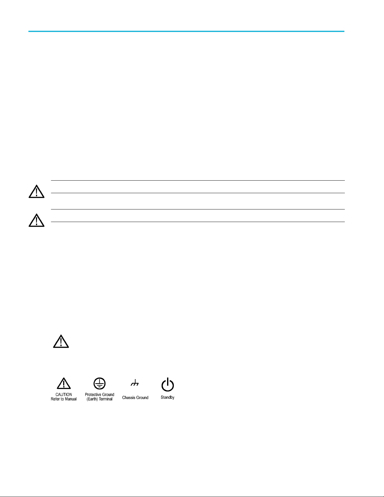
Symbols on the product
When this symbol is marked on the product, be sure to consult the manual to find out the nature of the potential
hazards and any actions which have to be taken to avoid them. (This symbol may also be used to refer the user to
ratings in the manual.)
The following symbols may appear on the product:
xii MDO4000C Series Oscilloscope User Manual
Page 17

Compliance Information
This section lists the EMC (electromagnetic compliance), safety, and environmental standards with which the instrument
complies.
EMC compliance
EC Declaration of Conformity – EMC
Meets intent of Directive 2004/108/EC for Electromagnetic Compatibility. Compliance was demonstrated to the following
specifications as listed in the Official Journal of the European Communities:
EN 61326-1, EN 61326-2-1. EMC requirements for electrical equipment for measurement, control, and laboratory use.
■
CISPR 11. Radiated and conducted emissions, Group 1, Class A
■
IEC 61000-4-2. Electrostatic discharge immunity
■
IEC 61000-4-3. RF electromagnetic field immunity
■
IEC 61000-4-4. Electrical fast transient / burst immunity
■
IEC 61000-4-5. Power line surge immunity
■
IEC 61000-4-6. Conducted RF immunity
1 2 3
4
5
6
1
This product is intended for use in nonresidential areas only. Use in residential areas may cause electromagnetic interference.
2
Emissions which exceed the levels required by this standard may occur when this equipment is connected to a test object.
3
Equipment may not meet the immunity requirements of applicable listed standards when test leads and/or test probes are connected due to coupling of electromagnetic
interference onto those leads/probes. To minimize the influence of electromagnetic interference, minimize the loop area between the unshielded portions of signal and
associated return leads, and keep leads as far away as possible from electromagnetic disturbance sources. Twisting unshielded test leads together is an effective way to
reduce loop area. For probes, keep the ground return lead as short as possible and close to the probe body. Some probes have accessory probe tip adapters to
accomplish this most effectively. In all cases, observe all safety instructions for the probes or leads used.
4
For compliance with the EMC standards listed here, high quality shielded interface cables should be used.
5
≤ 4.0 division waveform displacement or
Residual spurious signals in the RF section can typically increase to -65 dBm when the instrument is subjected to electromagnetic interference per the IEC
61000-4-3 test for frequencies up to 1 GHz, and to -45 dBm for frequencies above 1GHz.
6
≤ 4.0 division waveform displacement or ≤ 8.0 division increase in peak-to-peak noise.
Residual spurious signals in the RF section can typically increase to -80 dBm when the instrument is subjected to electromagnetic interference per the IEC
61000-4-6 test.
≤ 8.0 division increase in peak-to-peak noise.
MDO4000C Series Oscilloscope User Manual xiii
Page 18

Compliance Information
■
IEC 61000-4-8. Power frequency magnetic field immunity test
■
IEC 61000-4-11. Voltage dips and interruptions immunity
EN 61000-3-2. AC power line harmonic emissions
EN 61000-3-3. Voltage changes, fluctuations, and flicker
Australia / New Zealand Declaration of Conformity – EMC
Complies with the EMC provision of the Radiocommunications Act per the following standard, in accordance with ACMA:
■
CISPR 11. Radiated and conducted emissions, Group 1, Class A, in accordance with EN 61326-1 and EN 61326-2-1.
Russian federation
This product is approved by the Russian government to carry the GOST mark.
Safety compliance
This section lists the safety standards with which the product complies and other safety compliance information.
EU declaration of conformity – low voltage
Compliance was demonstrated to the following specification as listed in the Official Journal of the European Union:
Low Voltage Directive 2006/95/EC.
■
EN 61010-1. Safety Requirements for Electrical Equipment for Measurement, Control, and Laboratory Use – Part 1: General
Requirements.
■
EN 61010-2-030. Safety Requirements for Electrical Equipment for Measurement, Control, and Laboratory Use – Part
2-030: Particular requirements for testing and measuring circuits.
U.S. nationally recognized testing laboratory listing
■
UL 61010-1. Safety Requirements for Electrical Equipment for Measurement, Control, and Laboratory Use – Part 1: General
Requirements.
■
UL 61010-2-030. Safety Requirements for Electrical Equipment for Measurement, Control, and Laboratory Use – Part
2-030: Particular requirements for testing and measuring circuits.
xiv MDO4000C Series Oscilloscope User Manual
Page 19

Compliance Information
Canadian certification
■
CAN/CSA-C22.2 No. 61010-1. Safety Requirements for Electrical Equipment for Measurement, Control, and Laboratory Use
– Part 1: General Requirements.
■
CAN/CSA-C22.2 No. 61010-2-030. Safety Requirements for Electrical Equipment for Measurement, Control, and Laboratory
Use – Part 2-030: Particular requirements for testing and measuring circuits.
Additional compliances
■
IEC 61010-1. Safety Requirements for Electrical Equipment for Measurement, Control, and Laboratory Use – Part 1:
General Requirements.
■
IEC 61010-2-030. Safety Requirements for Electrical Equipment for Measurement, Control, and Laboratory Use – Part
2-030: Particular requirements for testing and measuring circuits.
Equipment type
Test and measuring equipment.
Safety class
Class 1 – grounded product.
Pollution degree description
A measure of the contaminants that could occur in the environment around and within a product. Typically the internal
environment inside a product is considered to be the same as the external. Products should be used only in the environment for
which they are rated.
■
Pollution Degree 1. No pollution or only dry, nonconductive pollution occurs. Products in this category are generally
encapsulated, hermetically sealed, or located in clean rooms.
■
Pollution Degree 2. Normally only dry, nonconductive pollution occurs. Occasionally a temporary conductivity that is caused
by condensation must be expected. This location is a typical office/home environment. Temporary condensation occurs only
when the product is out of service.
■
Pollution Degree 3. Conductive pollution, or dry, nonconductive pollution that becomes conductive due to condensation.
These are sheltered locations where neither temperature nor humidity is controlled. The area is protected from direct
sunshine, rain, or direct wind.
■
Pollution Degree 4. Pollution that generates persistent conductivity through conductive dust, rain, or snow. Typical outdoor
locations.
Pollution degree
Pollution Degree 2 (as defined in IEC 61010-1). Note: Rated for indoor, dry location use only.
IP rating
IP20 (as defined in IEC 60529).
Measurement and overvoltage category descriptions
Measurement terminals on this product may be rated for measuring mains voltages from one or more of the following categories
(see specific ratings marked on the product and in the manual).
■
Measurement Category II. For measurements performed on circuits directly connected to the low-voltage installation.
■
Measurement Category III. For measurements performed in the building installation.
■
Measurement Category IV. For measurements performed at the source of low-voltage installation.
MDO4000C Series Oscilloscope User Manual xv
Page 20

Compliance Information
NOTE. Only mains power supply circuits have an overvoltage category rating. Only measurement circuits have a measurement
category rating. Other circuits within the product do not have either rating.
Mains overvoltage category rating
Overvoltage Category II (as defined in IEC 61010-1)
Environmental compliance
This section provides information about the environmental impact of the product.
Product end-of-life handling
Observe the following guidelines when recycling an instrument or component:
Equipment recycling. Production of this equipment required the extraction and use of natural resources. The equipment may
contain substances that could be harmful to the environment or human health if improperly handled at the product’s end of life.
To avoid release of such substances into the environment and to reduce the use of natural resources, we encourage you to
recycle this product in an appropriate system that will ensure that most of the materials are reused or recycled appropriately.
This symbol indicates that this product complies with the applicable European Union requirements according to
Directives 2012/19/EU and 2006/66/EC on waste electrical and electronic equipment (WEEE) and batteries.
Perchlorate materials. This product contains one or more type CR lithium batteries. According to the state of California, CR
lithium batteries are classified as perchlorate materials and require special handling.
xvi MDO4000C Series Oscilloscope User Manual
Page 21
Preface
This manual provides operating information the following oscilloscopes:
MDO4024C MDO4034C MDO4054C MDO4104C
Key features
MDO4000C Mixed Domain Oscilloscopes include up to six built-in instruments, each with exceptional performance to address
tough challenges. Every oscilloscope features powerful triggering, search and analysis, and these are the only scopes to offer
synchronized analog, digital, and RF signal analysis. The MDO4000C is completely customizable and fully upgradeable.
■
Models are available with bandwidths from 200 MHz to 1 GHz
■
Sample rates of either 2.5 or 5 GS/s on all analog channels depending on the model
■
20 M points record length on all channels
■
>340,000 waveforms/second maximum waveform capture rate
■
A dedicated RF input channel for frequency domain measurements (optional)
■
Time-synchronized acquisition of analog, digital, and RF signals in a single instrument
■
50 MHz arbitrary/function generator (optional)
■
16 digital channels and four analog channels for time domain measurements (optional)
■
Advanced triggering and analysis: I2C, SPI, USB 2.0, CAN, LIN, FlexRay, RS-232, RS-422, RS-485, UART, I2S, Left
Justified (LJ), Right Justified (RJ), TDM, Ethernet, MIL-STD-1553 (with the appropriate application module), and Parallel
(optional)
■
Power analysis, and limit and mask testing application modules (optional)
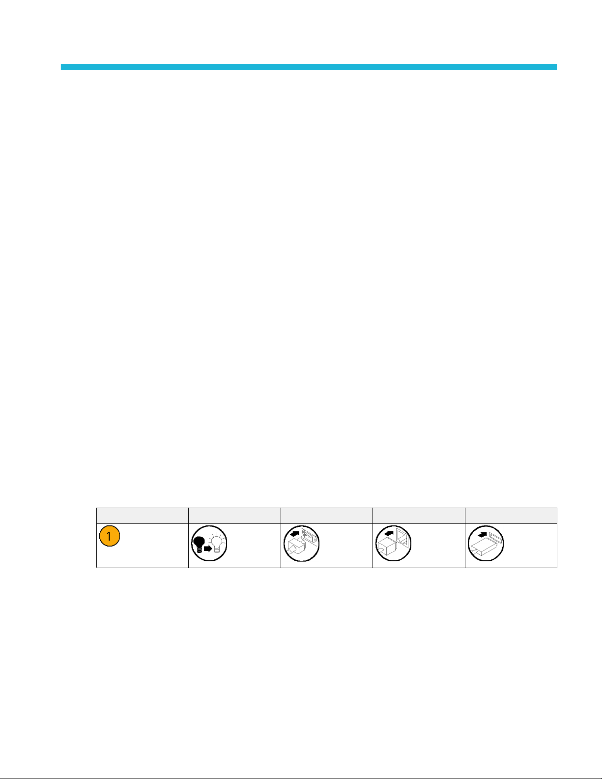
Conventions used in this manual
The following icons are used throughout this manual.
Sequence Step Front panel power Connect power Network USB
Warranty
Three-year warranty covering all parts and labor, excluding probes.
MDO4000C Series Oscilloscope User Manual xvii
Page 22

Preface
xviii MDO4000C Series Oscilloscope User Manual
Page 23

Installation
Before installation
Unpack the oscilloscope and check that you received all items listed as standard accessories. The following pages list
recommended accessories and probes, instrument options, and upgrades.
All products are shipped with a printed Installation and Safety manual that is in English, Japanese, Simplified Chinese, and
French.
Table 1: Standard accessories
Accessory Description Tektronix part number
MDO4000C Series Oscilloscopes User
Manual
Calibration certificate documenting
traceability to national metrology
institute(s), and ISO9001 quality system
registration.
English (Option L0) 077-1167-XX
French (Option L1) 077-1168-XX
Italian (Option L2) 077-1170-XX
German (Option L3) 077-1169-XX
Spanish (Option L4) 077-1171-XX
Japanese (Option L5) 077-1177-XX
Portuguese (Option L6) 077-1172-XX
Simplified Chinese (Option L7) 077-1174-XX
Traditional Chinese (Option L8) 077-1175-XX
Korean (Option L9) 077-1176-XX
Russian (Option L10) 077-1173-XX
– –
MDO4000C Series Oscilloscope User Manual 1
Page 24

Installation
Accessory Description Tektronix part number
Front Panel Overlay
When selecting a language option, you
will receive two front-panel overlays in the
language selected. Use the overlay that
matches your instrument.
Probes For 200, 350 and 500 MHz models, one
Adapter, for models with options SA3 or
SA6
Front Cover Hard plastic cover to help protect the
Power Cord North America (Option A0) 161-0348-00
French (Option L1) SA version
Non-SA version
Italian (Option L2) SA version
Non-SA version
German (Option L3) SA version
Non-SA version
Spanish (Option L4) SA version
Non-SA version
Japanese (Option L5) SA version
Non-SA version
Portuguese (Option L6) SA version
Non-SA version
Simplified Chinese (Option L7) SA
version
Non-SA version
Traditional Chinese (Option L8) SA
version
Non-SA version
Korean (Option L9) SA version
Non-SA version
Russian (Option L10) SA version
Non-SA version
500 MHz, 10X passive probe per channel
For 1 GHz models, one 1 GHz, 10X
passive probe per channel
N Male to BNC Female 103-0045-00
instrument
Universal Euro (Option A1) 161-0343-00
United Kingdom (Option A2) 161-0344-00
Australia (Option A3) 161-0346-00
Switzerland (Option A5) 161-0347-00
Japan (Option A6) 161-0342-00
China (Option A10) 161-0341-00
India (Option A11) 161-0349-00
Brazil (Option A12) 161-0356-00
No power cord or AC adapter (Option
A99)
335-3598-XX
335-3608-XX
335-3600-XX
335-3610-XX
335-3601-XX
335-3611-XX
335-3602-XX
335-3612-XX
335-3603-XX
335-3613-XX
335-3604-XX
335-3614-XX
335-3605-XX
335-3615-XX
335-0306-XX
335-3616-XX
335-3607-XX
335-3617-XX
335-3599-XX
335-3609-XX
TPP0500B
TPP1000
200-5130-00
– –
2 MDO4000C Series Oscilloscope User Manual
Page 25

Installation
Accessory Description Tektronix part number
Logic probe, with Option MDO4MSO One, 16-channel logic probe, with
accessories
Probe and accessory pouch Bag to hold probes and related
accessories
P6616
016-2030-XX
Table 2: Optional accessories
Accessory Description Tektronix part number
Aerospace serial triggering and analysis
application module
Audio serial triggering and analysis
application module
Automotive serial triggering and analysis
application module
FlexRay, CAN, and LIN serial triggering
and analysis application module
Bundle application module This module enables functionality for
Computer triggering and analysis
application module
This module enables triggering on MILSTD-1553 serial buses. Also, it provides
digital views of the signal, bus views, bus
decoding, search tools, and decode
tables with time stamp information.
This module enables triggering on I2S,
Left Justified (LJ), Right Justified (RJ),
and TDM audio buses. Also, it provides
digital views of the signal, bus views,
packet decoding, search tools, and
packet decode tables with time stamp
information
This module enables triggering on packet
level information on CAN and LIN serial
buses. Also, it provides a digital view of
the signal, bus view, packet decoding,
search tools, and a packet decode table
with time stamp information.
This module enables triggering on packet
level information in FlexRay, CAN, and
LIN buses. Also, it provides digital views
of the signal, bus views, packet decoding,
search tools, packet decode tables with
time stamp information and eye diagram
analysis software.
DPO4AERO, DPO4AUDIO, DPO4AUTO,
DPO4COMP, DPO4EMBD, DPO4ENET,
DPO4LMT, DPO4PWR, DPO4USB, and
DPO4VID
This module enables triggering on
RS-232, RS-422, RS-485 and UART
serial buses. Also, it provides digital views
of the signal, bus views, packet decoding,
search tools, and packet decode tables
with time stamp information.
DPO4AERO
DPO4AUDIO
DPO4AUTO
DPO4AUTOMAX
DPO4BND
DPO4COMP
MDO4000C Series Oscilloscope User Manual 3
Page 26

Installation
Accessory Description Tektronix part number
Embedded serial triggering and analysis
application module
Ethernet serial triggering and analysis
application module
This module enables triggering on packet
level information on I2C and SPI serial
buses. Also, it provides digital views of
the signal, bus views, packet decoding,
search tools, and packet decode tables
with time stamp information.
This module enables triggering on
10BASE-T and 100BASE-TX buses. Also,
it provides search tools, bus views, and
decode tables with time stamp
information.
NOTE. ≥350 MHz bandwidth models are
recommended for 100BASE-TX.
DPO4EMBD
DPO4ENET
Limit and mask test application module This module supports limit testing and
testing on telecom standard masks or
custom masks.
NOTE. ≥350 MHz bandwidth models are
recommended for Telecomm standards
>55 Mb/s. 1 GHz bandwidth models are
recommended for high-speed (HS) USB.
Power analysis application module This module supports measurements of
power quality, switching loss, harmonics,
ripple, modulation, safe operating area,
and slew rate (dV/dt and dI/dt).
Universal Serial Bus triggering and
analysis application module
This module enables triggering on packet
level information on USB 2.0 serial buses.
Also, it provides digital views of the
signal, bus views, bus decoding data in
hex, binary, and ASCII, search tools, and
packet decode tables with time stamp
information.
NOTE. 1 GHz bandwidth models are
required for high-speed (HS) USB.
DPO4LMT
DPO4PWR
DPO4USB
Extended video application module This module enables triggering on a
variety of standard HDTV signals, as well
as on custom (non-standard) bilevel and
trilevel video signals with 3 to 4,000 lines.
Advanced RF triggering application
module (for instruments with options SA3
or SA6)
NEX-HD2HEADER Adapter that routes the channels from a
TEK-USB-488 Adapter GPIB to USB Adapter TEK-USB-488
4 MDO4000C Series Oscilloscope User Manual
This module enables triggering with RF
power as the source for Pulse Width,
Timeout, Runt, Logic, and Sequence
triggers.
Mictor connector to 0.1 inch header pins.
DPO4VID
MDO4TRIG
NEX-HD2HEADER
Page 27

Accessory Description Tektronix part number
Rackmount kit Adds rackmount brackets RMD5000
Soft transit case Case for carrying instrument ACD4000B
Hard transit case Traveling case, which requires use of the
soft transit case (ACD4000B).
MSO4000B, DPO4000B, MDO4000/B/C,
and MDO3000 Series Oscilloscopes
Programmer Manual
Describes commands for remote control
of the oscilloscope.
HCTEK54
077-0510-XX
Installation
MDO4000C Series Oscilloscopes
Specifications and Performance
Verification Technical Reference Manual
MDO4000C Series Oscilloscopes Service
Manual
MDO4000C Series Application Module
Installation Instructions
DPO3PWR and DPO4PWR Power
Measurement Module User Manual
MDO4000C Series Oscilloscopes
Declassification and Security Instructions
TekVPI Probes
Describes the oscilloscope specifications
and performance verification procedure.
Service information on MDO4000C Series
oscilloscopes.
Describes how to install application
modules on your oscilloscope.
English (Option L0) 071-2631-XX
French (Option L1) 077-0235-XX
Italian (Option L2) 077-0236-XX
German (Option L3) 077-0237-XX
Spanish (Option L4) 077-0238-XX
Japanese (Option L5) 077-0239-XX
Portuguese (Option L6) 077-0240-XX
Simplified Chinese (Option L7) 077-0241-XX
Traditional Chinese (Option L8) 077-0242-XX
Korean (Option L9) 077-0243-XX
Russian (Option L10) 077-0244-XX
Describes how to sanitize or remove
memory devices from the Tektronix
MDO4000C Series oscilloscopes.
Visit the Oscilloscope Probe and
Accessory Selector Tool on the Tektronix
website
077-1178-XX
077-1179-XX
071-3253-XX
077-1180-00
NOTE. A subset of TekVPI probes can be
used on the RF input as well. These
probes require the use of the TPA-N-VPI
adapter listed below.
TPA-N-VPI adapter Adapter from N connection (RF input) to
TekVPI probe.
TPA-BNC adapter TekVPI to TekProbe II BNC Adapter TPA-BNC
MDO4000C Series Oscilloscope User Manual 5
TPA-N-VPI
Page 28

Installation
6 MDO4000C Series Oscilloscope User Manual
Page 29
Installation
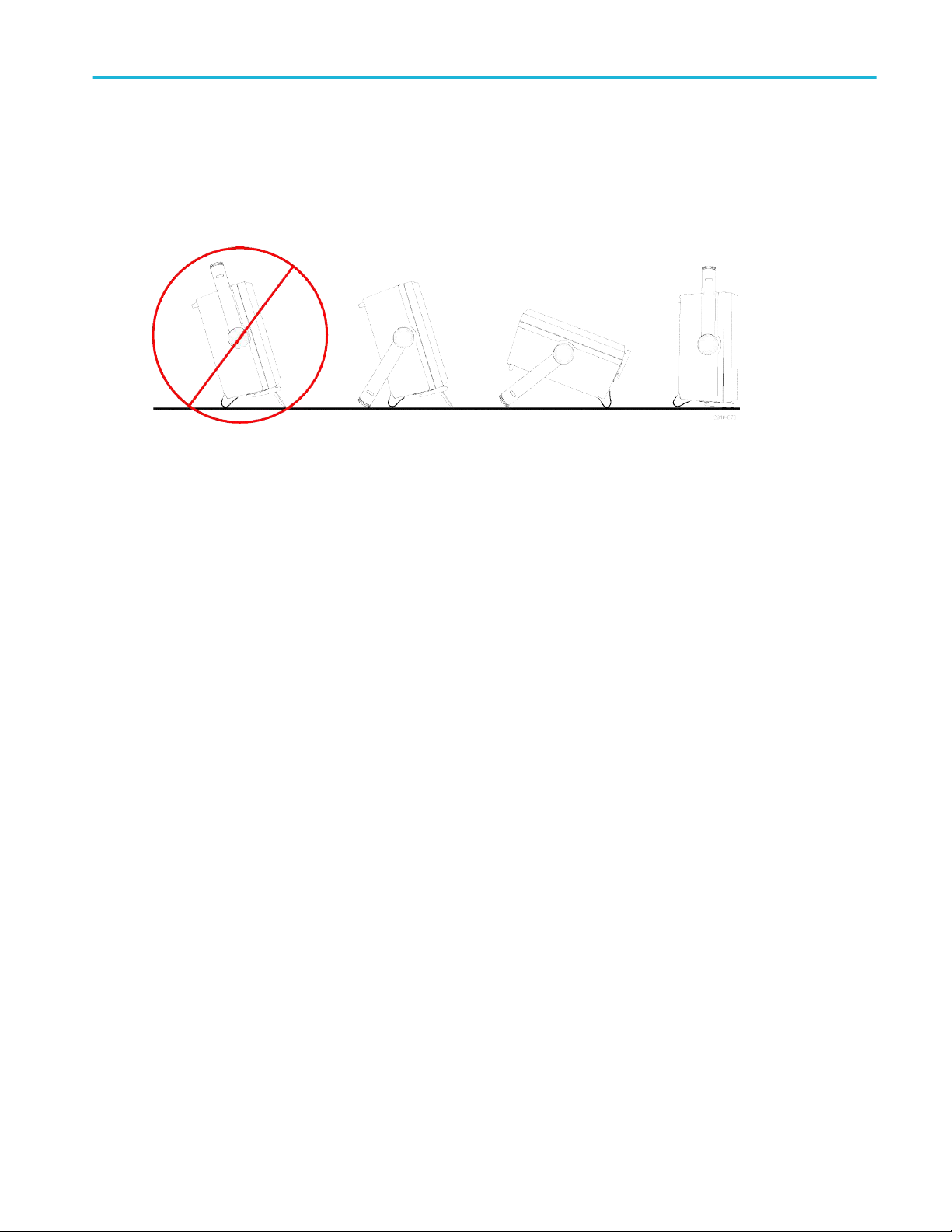
Operating positions
Use the handle and front flip feet to place the oscilloscope in a convenient operating position. When the feet are extended,
always have the handle in a down position.
MDO4000C Series Oscilloscope User Manual 7
Page 30
Installation
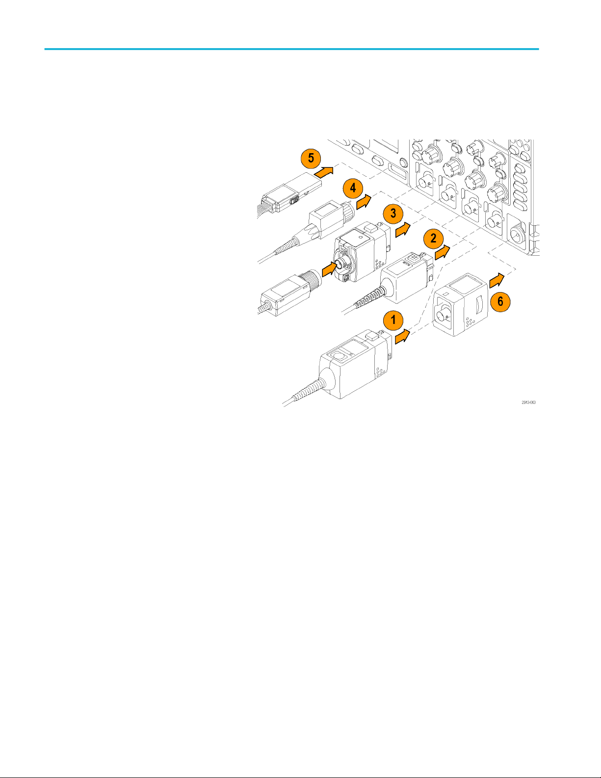
Connecting probes
The oscilloscope supports probes with the following:
1. Tektronix Versatile Probe Interface
(TekVPI)
These probes support two-way
communication with the oscilloscope
through on-screen menus and remotely
through programmable support. The
remote control is useful in applications
like ATE where you want the system to
preset probe parameters.
2. Tektronix Versatile Probe Interface
(TekVPI) for Passive Probes
These probes build upon the functionality
of the TekVPI interface. Each probe is
matched with its corresponding
oscilloscope channel, allowing the
oscilloscope to optimize the signal input
path. This provides AC compensation
across the frequency band.
3. TPA-BNC Adapter
The TPA-BNC Adapter allows you to use
TEKPROBE II probe capabilities, such as
providing probe power, and passing
scaling and unit information to the
oscilloscope.
8 MDO4000C Series Oscilloscope User Manual
Page 31

Installation
4. BNC Interfaces
Some of these use TEKPROBE
capabilities to pass the waveform signal
and scaling to the oscilloscope. Some
only pass the signal and there is no other
communication.
5. Logic Probe Interface
The P6616 probe provides 16 channels
of digital (on or off state) information.
6. The TPA-N-VPI Adapter allows you to
use TekVPI probes in the RF input.
For more information on the many probes available for use with MDO4000C Series oscilloscopes, visit the Oscilloscope Probe
and Accessory Selector Tool on the Tektronix website
MDO4000C Series Oscilloscope User Manual 9
Page 32

Installation
Securing the oscilloscope
1. Use a standard laptop computer style
security lock to secure your oscilloscope
to your location.
Power-On
1. Connect the supplied power cord to the rear-panel power connector.
2. Push the power button on the instrument front-panel and the instrument will turn on.
NOTE. The Standby button on the front-panel does not disconnect mains power. Only the power cord at the rear of the product
can disconnect mains power.
10 MDO4000C Series Oscilloscope User Manual
Page 33

Installation
Powering off the oscilloscope
To power off the oscilloscope, push the power button on the front of the oscilloscope.
To de-energize the instrument, cycle the power button on the instrument front panel to off, and then remove the power cord.
MDO4000C Series Oscilloscope User Manual 11
Page 34

Installation
Functional check
Perform this quick functional check to verify that your oscilloscope is operating correctly.
1. Connect the oscilloscope power cable.
2. Power on the oscilloscope.
3. Connect the probe connector to
oscilloscope channel 1 and the probe tip
and reference lead to the PROBE COMP
terminals on the right side of the
oscilloscope front panel.
4. Push Default Setup.
12 MDO4000C Series Oscilloscope User Manual
Page 35

Installation
5. Push Autoset. The screen should now
display a square wave, approximately
2.5 V at 1 kHz.
If the signal appears but is misshapen,
perform the procedures for compensating
the probe.
If no signal appears, rerun the procedure.
If this does not remedy the situation, have
the instrument serviced by qualified
service personnel.
MDO4000C Series Oscilloscope User Manual 13
Page 36

5
6
7
8
Installation
Compensating a TPP0500B or TPP1000 passive voltage probe
Your Tektronix oscilloscope can automatically compensate TPP0500B and TPP1000 probes. This eliminates the need for
manual probe compensation, as is typically performed with other probes.
Each compensation generates values for a specific probe and channel combination. If you want to use the probe on another
channel and desire to compensate the new probe-channel pair, you must run a new set of compensation steps for that new
combination.
1. Connect the oscilloscope power cable.
2. Connect the oscilloscope power cable.
3. Connect the probe connector to the oscilloscope channel, and the probe tip and reference lead to the PROBE COMP
terminals on the oscilloscope front panel.
NOTE. Connect only one probe at a time to the probe comp terminals.
4. Push a front panel button for an input
channel connected to the probe you wish
to compensate. (1, 2, 3, or 4)
5. Notice on the lower menu that the
oscilloscope has automatically set the
probe termination value.
6. Push More repeatedly to select Probe
Setup from the resulting pop-up menu.
7. Notice that the compensation status
starts as Default.
8. Push Compensate probe and follow the
instructions that appear on the display.
DC |ACTermination set
Coupling
TPP1000 Probe
Setup
SN:
000001 Atten:
10X
Compensation
Status
Default
Compensate
probe for 1
Measure
Current
No
Yes |
by TPP1000
On |
Invert
Off
More
Full Label
Bandwidth
14 MDO4000C Series Oscilloscope User Manual
Page 37

Installation
When compensating TPP0500B/TPP1000 probes on the oscilloscope:
■
Each compensation generates values for a specific probe and channel combination. If you want to use the probe on another
channel and desire to compensate the new probe-channel pair, you must run a new set of compensation steps.
■
Each channel can store compensation values for 10 individual probes. If you try to compensate an 11th probe on a channel,
the oscilloscope will delete the values for the least recently used probe and add the values for the new probe.
■
The oscilloscope will assign default compensation values to a TPP0500B or TPP1000 probe connected to the Aux In
channel.
NOTE. A factory calibration will delete all stored compensation values
NOTE. A probe compensation failure is most likely due to intermittent connection of the probe tip or ground connection during the
probe compensation operation. If a failure occurs, the oscilloscope will re-use the old probe compensation values, if they existed
prior to the failed probe compensation operation.
MDO4000C Series Oscilloscope User Manual 15
Page 38

Installation
Compensating a non-TPP0500B or non-TPP1000 passive voltage probe
Whenever you attach a passive voltage probe for the first time to any input channel, compensate the probe to match it to the
corresponding oscilloscope input channel.
If you are interested in using the automatic probe compensation procedure described above for the TPP0500B and TPP1000
probes See GUID-C0DD4580-7DCF-46A8-81FC-738AEA7742D1#GUID-C0DD4580-7DCF-46A8-81FC-738AEA7742D1. on a
non-TPP0500B/TPP1000 Tektronix passive probe, check the instruction manual for your probe to see if it qualifies. Otherwise, to
properly compensate your passive probe:
1. Follow the steps for the functional check.
See Functional check on page
12.
2. Check the shape of the displayed
waveform to determine if your probe is
properly compensated.
3. If necessary, adjust your probe. Repeat
as needed.
Quick Tips
Use the shortest possible ground lead and signal path to minimize probe-induced ringing and distortion on the measured signal.
Properly compensated
Under compensated
Over compensated
Signal with a short ground lead
16 MDO4000C Series Oscilloscope User Manual
Signal with a long ground lead
Page 39

Installation
Application module free trial
A 30-day free trial is available for all application module licenses not installed in your oscilloscope. The trial period begins when
you power on the oscilloscope for the first time.
After 30 days, you must purchase the module if you want to continue using the application. To see the date when your free trial
period expires, push Utility on the front panel, push Utility Page on the lower menu, use multipurpose knob a to select Config,
push About on the lower menu, and then push Application Modules on the side menu to see the expiration date.
Installing an application module
CAUTION. To avoid damage to the oscilloscope or application module, observe ESD (electrostatic discharge) precautions. See
Power-On on page 10.
Turn off the oscilloscope power while removing or adding an application module.
See Powering off the oscilloscope on page 11.
Optional application module packages extend the capability of your oscilloscope.
You can physically install up to four application modules at one time. Application modules go into the two slots with windows in
the upper right corner of the front panel. Two additional slots are directly behind the two that you can see. To use these slots,
install the module with the label facing away from you.
Some of the modules have licenses which allow you to transfer the license between your application modules and the
oscilloscope. You can keep each license in the module, which will allow you to move the module from one instrument to another.
Alternatively, you can move the license from the module to the oscilloscope. This approach will allow you to store the module
separately from the oscilloscope for safe keeping. This approach will also allow you to use more than four applications on your
oscilloscope simultaneously. To transfer a license from a module to your oscilloscope or from your oscilloscope to a module:
1. Turn off the power to the oscilloscope. Insert the application modules into the oscilloscope. Turn on the power.
2. Push Utility on the front panel. If needed, push Utility Page on the lower menu and turn multipurpose knob a to select
Config. Push Manage Modules and Options on the lower menu, and then push License Type on the side menu until
“Modules” is selected. The licenses contained in the oscilloscope will be listed in the side menu. Push the button next to the
appropriate license to transfer. You may transfer up to four licenses at one time.
3. After you turn off the power to the oscilloscope, you can remove the physical application module from the oscilloscope.
Refer to the MDO3000 and MDO4000 Series Application Module Installation Manual that came with your application module for
instructions on installing and testing an application module.
NOTE. If you transfer a license from a module to an oscilloscope, the module will not work on another oscilloscope until you
transfer the license back from the oscilloscope to the module. Consider putting the physical module in an envelope or other
storage with a label recording the date, module name, model and serial number of the oscilloscope which holds the license. This
will help prevent confusion later if someone finds the module, installs it in some other oscilloscope, and wonders why it does not
work.
MDO4000C Series Oscilloscope User Manual 17
Page 40

Installation
Upgrading bandwidth
You may increase the bandwidth of an instrument when your project requirements demand higher performance. Do this by
purchasing an upgrade.
All upgrades require that you send your instrument to a Tektronix Service Center and require a full calibration.
Model to be upgraded Option SA3 or Option
SA6 (spectrum
analyzer)
MDO4024C No 200 MHz 350 MHz MDO4BW2T34
MDO4034C No 350 MHz 500 MHz MDO4BW3T54
MDO4054C No 500 MHz 1 GHz MDOBW5T104
MDO4024C Yes 200 MHz 350 MHz MDO4BW2T34-SA
MDO4034C Yes 350 MHz 500 MHz MDO4BW3T54-SA
MDO4054C Yes 500 MHz 1 GHz MDO4BS5T104-SA
Bandwidth before
upgrade
200 MHz 500 MHz MDO4BW2T54
200 MHz 1 GHz MDO4BW2T104
350 MHz 500 MHz MDO4BW3T54
350 MHz 1 GHz MDO4BW3T104
500 MHz 1 GHz MDO4BW5T104
350 MHz 1 GHz MDO4BW3T104
500 MHz 1 GHz MDO4BW5T104
200 MHz 500 MHz MDO4BW2T54-SA
200 MHz 1 GHz MDO4BW2T104-SA
350 MHz 500 MHz MDO4BW3T54-SA
350 MHz 1 GHz MDO4BW3T104-SA
500 MHz 1 GHz MDO4BW5T104-SA
350 MHz 1 GHz MDO4BW3T104-SA
500 MHz 1 GHz MDO4BW5T104-SA
Bandwidth after
upgrade
Order product
18 MDO4000C Series Oscilloscope User Manual
Page 41

5
6
Installation
Changing the language of the user interface or keyboard
To change the language of the oscilloscope user interface or keyboard, and to change the front panel button labels through the
use of an overlay:
1. Push Utility.
2. Push Utility Page.
3. Turn multipurpose knob a and select
Config.
4. Push Language from the resulting lower
menu.
5. Push Menus from the resulting side
menu and turn multipurpose knob a to
select the desired language for the user
interface.
6. Push USB Keyboard from the resulting
side menu and turn multipurpose knob a
to select the desired language version of
keyboard to use.
7. If you choose to use an English user
interface, be sure that the plastic front
panel overlay is removed.
If you choose a language other than
English, place the plastic overlay for the
language that you desire over the front
panel to display labels in that language.
Language
Menus
(a) English
USB Keyboard
English
NOTE. If you order a language option, you will receive two front-panel overlays in the language you ordered: One for models with
RF options (options SA3 or SA6) and one with no RF option. Follow the instructions that come with the front-panel overlays.
MDO4000C Series Oscilloscope User Manual 19
Page 42

Installation
Changing the date and time
To set the internal clock with the current date and time:
1. Push Utility.
2. Push Utility Page.
3. Turn multipurpose knob a and select Config.
5. Push the side menu buttons and turn both multipurpose knobs (a and b) to set the time and date values.
6. Push OK Set Date & Time.
20 MDO4000C Series Oscilloscope User Manual
Page 43

4
5
Installation
Signal path compensation for time and frequency domains
Signal Path Compensation (SPC) corrects for DC inaccuracies caused by temperature variations and/or long-term drift. Run the
compensation whenever the ambient temperature has changed by more than 10 °C (18 °F) or once a week if you use vertical
settings of 5 mV/division or less. Failure to do so may result in the instrument not meeting warranted performance levels at those
volts/div settings.
To compensate the signal path:
1. Warm up the oscilloscope for at least
20 minutes. Remove all input signals
(probes and cables) from channel inputs.
Input signals with AC components
adversely affect SPC.
2. Push Utility.
3. Push Utility Page.
4. Turn multipurpose knob a and select
Calibration.
5. Push Signal Path on the lower menu.
6. Push OK Compensate Signal Paths on
the resulting side menu.
The calibration will take approximately
10 minutes to complete.
Utility Page
Calibration
Signal Path
Pass
Factory
Pass
MDO4000C Series Oscilloscope User Manual 21
Page 44

7
7
Installation
7. After calibration, verify that the status
Utility Page
Calibration
Signal Path
Pass
Factory
indicator on the lower menu displays
Pass. If it does not, then recalibrate the
instrument or have the instrument
serviced by qualified service personnel.
Service personnel use the factory
calibration functions to calibrate the
internal voltage references of the
oscilloscope using external sources.
Contact your Tektronix field office or
representative for assistance with factory
calibration.
NOTE. Signal Path Compensation does not include calibration to the probe tip.
Pass
22 MDO4000C Series Oscilloscope User Manual
Page 45

Upgrading firmware
To upgrade the firmware of the oscilloscope:
Open up a Web browser and go to the
1.
tektronix website. Proceed to the software
finder. Download the latest firmware for
your oscilloscope on your PC.
Unzip the files and copy the firmware.img file
into the root folder of a USB flash drive or USB
hard drive.
2. Power off your oscilloscope.
Installation
3. Insert the USB flash or hard drive into the
USB port on the front panel of your
oscilloscope.
4. Power on the oscilloscope. The
instrument automatically recognizes the
replacement firmware and installs it.
If the instrument does not install the
firmware, rerun the procedure. If the
problem continues, try a different model
of USB flash or hard drive. Finally, if
needed, contact qualified service
personnel.
NOTE. Do not power off the oscilloscope
or remove the USB drive until the
oscilloscope finishes installing the
firmware.
MDO4000C Series Oscilloscope User Manual 23
Page 46

Installation
5. Power off the oscilloscope and remove
the USB flash or hard drive.
6. Power on the oscilloscope.
7. Push Utility.
8. Push Utility Page.
9. Turn multipurpose knob a and select
Config.
10. Push About.
11. Confirm that the version number matches that of the new firmware.
24 MDO4000C Series Oscilloscope User Manual
Page 47

Connecting your oscilloscope to a computer
Connect your oscilloscope directly to a computer to let the PC analyze your data, collect screen images, or to control your
oscilloscope.
Three ways to connect your oscilloscope to a computer are through the VISA drivers, the e*Scope Web-enabled tools, and a
socket server. Use VISA to communicate with your oscilloscope from your computer through a software application, such as
Tektronix OpenChoice Desktop®. Use e*Scope to communicate with your oscilloscope through a Web browser, such as
Microsoft Internet Explorer. For best results, use a browser that supports html 5.
Using VISA
VISA lets you use your MS-Windows computer to acquire data from your oscilloscope for use in an analysis package that runs on
your PC, such as Microsoft Excel, National Instruments LabVIEW, Tektronix OpenChoice Desktop software, or a program of your
own creation. You can use a common communications connection, such as USB, Ethernet, or GPIB, to connect the computer to
the oscilloscope.
For VISA, load the VISA drivers on your computer. Also, load your application, such as OpenChoice Desktop. You will find the
drivers and OpenChoice Desktop software on the Tektronix website
Using e*Scope
With e*Scope, you can access and control any Internet-connected MDO4000C Series oscilloscope from a web browser on your
computer.
Installation
Connect the oscilloscope to your network using the LAN port. The built-in LXI web interface (Core 2011, Version 1.4) provides
network configuration information, which you can edit and customize. It also provides remote instrument control through the
e*Scope user interface. There you can control instrument settings, save screen images, save instrument data or setups, and
much more. Do all this through a password-protectable web-interface.
To set up VISA communication between your oscilloscope and a computer, perform these steps.
Load the VISA drivers on your computer. Also, load your application, such as OpenChoice Desktop.
1.
2. Connect the oscilloscope to your computer with the appropriate USB or Ethernet cable.
To communicate between the oscilloscope and a GPIB system, connect the oscilloscope to the TEK-USB-488 GPIB-to-USB
Adapter with a USB cable. Then connect the adapter to your GPIB system with a GPIB cable. Cycle the power on the
oscilloscope.
3. Push Utility
4. Push
5. Turn the Multipurpose a and select I/O.
6. If you are using USB, the system sets itself up automatically for you, if USB is enabled.
Check USB on the lower menu to be sure that USB is enabled. If it is not enabled, push USB. Then push Connect to
Computer on the side menu.
7. To use Ethernet, push Ethernet & LXI on the lower menu.
.
Utility page.
Use the side menu buttons to adjust your network settings, as needed. For more information, see the e*Scope setup
information below.
8. If you want to change socket server parameters, push Socket Server and enter new values through the resulting side
menu.
9. If you are using GPIB, push GPIB. Enter the GPIB address on the side menu, by turning the Multipurpose a knob.
MDO4000C Series Oscilloscope User Manual 25
Page 48

Installation
This will set the GPIB address on an attached TEK-USB-488 Adapter.
10. Run your application software on your computer.
TIP.
■
The Tektronix website provides access to a variety of Windows-based software tools for efficient connectivity between your
oscilloscope and your computer. These include tool bars that speed connectivity with Microsoft Excel and Word and a
standalone acquisition program called Tektronix OpenChoice Desktop.
■
The rear-panel USB 2.0 device port is the correct USB port for computer connectivity. Use the rear and front panel USB
2.0 host port to connect your oscilloscope to USB flash drives. Use the USB Device port on the rear panel to connect your
oscilloscope to a PC or a PictBridge printer.
Using the LXI web page and e*Scope
With e*Scope, you can access any Internet-connected MDO4000C oscilloscope from a web browser on your computer or tablet.
To set up e*Scope communications between your oscilloscope and a Web browser running on a remote computer:
1. Connect the oscilloscope to your computer network with an appropriate Ethernet cable.
2. Push Utility.
3. Push Utility Page.
4. Turn Multipurpose knob and select I/O.
5. Push Ethernet & LXI.
6. View the top item on the side menu to determine the condition of the LAN. An indicator turns green for good status and red if
the device detects a fault.
7. Push LAN Settings to display the network parameters configured on your oscilloscope.
8. Push LAN Reset to restore the LAN defaults to your oscilloscope.
9. Push Test Connection to check if your oscilloscope can find an attached network.
10. Push more to see another page of side menu items.
11. Push Change Names to change the name of the oscilloscope, the network domain, or the service name.
12. Push Change Ethernet & LXI Password to change the name of the password.
13. Push Change e*Scope Password to use the LXI password to also protect your oscilloscope from changes made to LAN
settings from a Web browser.
14. Start your browser on your remote computer. In the browser address line, enter the host name, a dot, and the domain name
together. Alternatively, just enter the IP address of the instrument. Either way, you should then see the LXI Welcome page
on your Web browser on your computer screen.
15. Click Network Configuration to view and edit the network configuration settings. If you are using a password and changing
your settings, you need to know that the default user name is “lxiuser”.
16. For e*Scope, click the Instrument Control (e*Scope) link on the left side of the LXI Welcome page. You should then see a
new tab (or window) open in your browser with e*Scope running.
Using a socket server
A socket server provides two-way communication over an Internet Protocol-based computer network. You can use your
oscilloscope’s socket server feature to let your oscilloscope communicate with a remote-terminal device or computer.
26 MDO4000C Series Oscilloscope User Manual
Page 49

Installation
To set up and use a socket server between your oscilloscope and a remote terminal or computer:
1. Push the Utility button.
2. Push Utility Page.
3. Turn Multipurpose a and select I/O.
4. Push Socket Server.
5. On the resulting Socket Server side menu, push the top entry to highlight Enabled.
6. Choose whether the protocol should be None or Terminal.
A communication session run by a human at a keyboard typically uses a terminal protocol. An automated session might
handle its own communications without such protocol from the oscilloscope.
7. If required, change the port number by turning Multipurpose a.
8. If required, press OK to set the new port number.
9. After you have set up the socket server parameters, the computer is now ready to communicate with the oscilloscope. If you
are running an MS Windows PC, you could run its default client Telnet, which has a command interface. One way to do this
is by typing “ Telnet ” in the Run window. The Telnet window will open on the PC.
NOTE. On MS Windows 7, you must first enable Telnet in order for Telnet to work.
10. Start a terminal session between your computer and your oscilloscope by typing in an open command with the
oscilloscope's LAN address and port #.
You can obtain the LAN address by pushing the Ethernet & LXI lower menu button and the resulting LAN Settings side
menu button to view the resulting Ethernet and LXI Settings screen. You can obtain the port # by pushing Socket Server on
the lower menu and viewing Current Port on the side menu.
For example, if the oscilloscope IP address was 123.45.67.89 and the post # was the default of 4000, you could open a
session by writing into the MS Windows Telnet screen: o 123.45.67.89 4000.
The oscilloscope will send a help screen to the computer when it has finished connecting.
11. You can now type in a standard query, such as, *idn?.
The Telnet session window will respond by displaying a character string describing your instrument.
You can type in more queries and view more results using this Telnet session window. You can find the syntax for relevant
commands, queries and related status codes in the Programmer Manual that is available at the Tektronix website.
NOTE. Do not use the computer’s backspace key during an MS Windows Telnet session with the oscilloscope.
MDO4000C Series Oscilloscope User Manual 27
Page 50

Installation
Connecting a USB keyboard to your oscilloscope
You can connect a USB keyboard to a USB Host port on the rear or front panel of the oscilloscope. The oscilloscope will detect
the keyboard, even if it is plugged in while the oscilloscope is powered on.
You can use the keyboard to quickly create names or labels. You can bring up the Label button on the lower menu by pushing a
Channel or Bus button. Use the arrow keys on the keyboard to move the insertion point, and then type in a name or label.
Labeling channels and buses makes the information on the screen easier to identify.
To choose whether to use a keyboard with a United States (US) key layout or one with an alternative layout:
1. Push Utility.
2. Push Utility Page.
3. Turn multipurpose knob a and select Config.
4. Push Language on the lower menu.
5. Push USB Keyboard on the side menu.
6. Turn multipurpose knob a and select the desired keyboard layout style from the resulting menu.
28 MDO4000C Series Oscilloscope User Manual
Page 51

Get acquainted with the instrument
Front-panel menus, controls, and connectors
The front panel has buttons and controls for the functions that you use most often. Use the menu buttons to access more
specialized functions.
1. Traditional oscilloscope front panel controls
2. 10-digit keypad
3. Application module slots
4. Ground strap connector
5. Ground
6. PROBE COMP
7. Auxiliary Input (only on instruments without option SA3 or SA6)
8. Dedicated spectral analysis controls, available with Option SA3 and SA6
9. Dedicated RF input with N-connector, available with Option SA3 and SA6
10. Analog channel (1, 2, 3, 4) inputs with TekVPI versatile probe interface
11. Digital channel input
12. Display: shows frequency and/or time domain
13. Arbitrary/function generator (AFG) enable button
MDO4000C Series Oscilloscope User Manual 29
Page 52

Get acquainted with the instrument
Front panel menus and controls
The front panel has buttons and controls for the functions that you use most often. Use the menu buttons to access more
specialized functions.
Using the menu system
To use the menu system:
1. Push a front panel menu button to display the menu that you want to use.
NOTE. The B1, B2, and B3 buttons support multiple serial or parallel buses.
2. Push a lower menu button. If a pop-out menu appears, turn Multipurpose a knob to select the desired choice. If a pop-up
menu appears, push the button again to select the desired choice.
3. Push a side menu button.
If the menu item contains more than one choice, push the side button repeatedly to cycle through the choices.
If a pop-out menu appears, turn Multipurpose a knob to select the desired choice.
4. To remove a side menu, push the lower button again or push Menu Off.
30 MDO4000C Series Oscilloscope User Manual
Page 53

Get acquainted with the instrument
5. Certain menu choices require you to set a numeric value to complete the setup. Use the upper and lower multipurpose
knobs a and b to adjust values. You can also set many numerical values with the 10-digit keypad on the front panel.
6. Push Fine to turn off or on the ability to make smaller adjustments.
Using the menu buttons
Use the menu buttons to perform many functions in the oscilloscope.
1.
Measure. Push to perform automated measurements on waveforms and to access the digital voltmeter (DVM) and
waveform histogram functions.
2. Search. Push to perform an automated search through an acquisition for user-defined events/criteria.
3. Autoset. Push to perform an automatic setup of oscilloscope settings.
4. Test. Push to activate advanced or application-specific testing features.
MDO4000C Series Oscilloscope User Manual 31
Page 54

Get acquainted with the instrument
5. Acquire. Push to set the acquisition mode and adjust the record length.
Trigger Menu. Push to specify trigger settings.
6.
7. M. Push to manage the math waveform, including the display or removal of the math waveform from the display.
8. R. Push to manage reference waveforms, including the display or removal of each reference waveform from the display.
9. B1, B2, or B3. Push to define a serial bus if you have the appropriate modules. Parallel bus support is available on
MDO4000C products with the MDO4MSO option installed. Push the appropriate button to display or remove the
corresponding bus from the display.
10. AFG. Push to enable the arbitrary/function generator output and access the AFG menu.
11. Vertical Position. Turn to adjust the vertical position of the corresponding waveform. Push to center the waveform baseline
indicator.
12. Channel 1, 2, 3 or 4 Menu. Push to set vertical parameters for input waveforms and to display or remove the corresponding
waveform from the display.
13. Vertical Scale. Turn to adjust the vertical scale factor of the corresponding waveform (volts/division). Push to toggle
between Fine and Coarse adjustment.
Below the display buttons
Use the buttons below the display to perform many functions in the oscilloscope.
1. Save / Recall Menu. Push to define the Save button to save and recall setups, waveforms, or screen images to internal
memory, a USB flash drive, or a mounted network drive.
Default Setup. Push to perform an immediate restore of the oscilloscope to the default settings.
2.
32 MDO4000C Series Oscilloscope User Manual
Page 55

Get acquainted with the instrument
3. Utility. Push to activate the system utility functions, such as selecting a language or setting the date/time.
4. B1, B2, or B3. Push to define and display a bus if you have the appropriate module application keys.
■
DPO4AERO supports MIL-STD-1553 buses.
■
DPO4AUDIO supports I2S, Left Justified (LJ), Right Justified (RJ), and TDM buses.
■
DPO4AUTO supports CAN and LIN buses.
■
DPO4AUTOMAX supports CAN, LIN and FlexRay, including physical layer testing on FlexRay.
■
DPO4BND adds support for DPO4AERO, DPO4AUDIO, DPO4AUTO, DPO4COMP, DPO4EMBD, DPO4ENET,
DPO4USB, DPO4LMT, DPO4PWR, and DPO4VID.
■
DPO4COMP supports RS-232, RS-422, RS-485, and UART buses.
■
DPO4EMBD supports I2C and SPI buses.
■
DPO4ENET supports 100BASE-T and 1000BASE-T buses.
■
DPO4USB supports USB 2.0 buses.
Push the B1, B2, or B3 button to display or remove the corresponding bus from the display.
■
MDO4TRIG supports advanced RF power level triggering.
■
MDO4MSO adds 16 digital channels; includes P6616 digital probe and accessories .
■
MDO4AFG adds the arbitrary/function generator to any MDO4000C Series product.
R. Push to manage reference waveforms and traces, including the display or removal of each reference waveform or trace
5.
from the display.
6. M. Push to manage the math waveform or trace, including the display or removal of the math waveform or trace from the
display.
MDO4000C Series Oscilloscope User Manual 33
Page 56

Get acquainted with the instrument
Using spectral analysis controls
These buttons configure the acquisition and display of the RF input.
RF. Push to bring up the frequency domain display and menu. The RF menu provides access to the Spectrogram display.
1.
2. Freq/Span. Push to specify the portion of the spectrum to view on the display. Set the center frequency and the span – or
set the start and stop frequency.
3. Ampl. Push to set the reference level.
4. BW. Push to define the resolution bandwidth.
5. Markers. Push to set automatic or manual markers.
Using other controls
Cursors. Push once to activate the two vertical cursors. Push again to turn off all cursors. Push and hold to bring up the
1.
cursor menu. Use the menu to select the cursor features, such as type, source, orientation, linked status, and units.
When the cursors are on, you can turn the multipurpose knobs to control their position.
2. Turn the upper multipurpose knob a, when activated, to move a cursor, to set a numerical parameter value for a menu item,
or to select from a pop-out list of choices. Push the Fine button to toggle between coarse and fine adjustment.
Screen icons tell you when a or b are active.
3. Select. Push to activate special functions.
For example, when using the two vertical cursors (and no horizontal ones are visible), you can push this button to link or
unlink the cursors. When the two vertical and two horizontal cursors are both visible, you can push this button to make either
the vertical cursors or the horizontal cursors active.
4. Fine. Push to toggle between making coarse and fine adjustments with the many operations of multipurpose knobs a and b.
5. Turn the lower Multipurpose b knob, when activated, to move a cursor or set a numerical parameter value for a menu item.
Push Fine to make adjustments more slowly.
34 MDO4000C Series Oscilloscope User Manual
Page 57

Get acquainted with the instrument
6. Intensity. Push to enable Multipurpose a to control waveform display intensity and knob b to control graticule intensity.
7.
Zoom button. Push to activate zoom mode.
8. Pan (outer knob). Turn to scroll the zoom window through the acquired waveform.
9. Zoom-scale (inner knob). Turn to control the zoom factor. Turning it clockwise zooms in further. Turning it counterclockwise
zooms out.
10. Play-pause button. Push to start or stop the automatic panning of a waveform. Control the speed and direction with the pan
knob.
11. ← Prev. Push to jump to the previous waveform mark.
12. Set/Clear Mark. Push to establish or delete a waveform mark.
13. → Next. Push to jump to the next waveform mark.
Horizontal Position. Turn to adjust the trigger point location relative to the acquired waveforms. Push to center when delay
14.
is on. Push to set to 10% when delay is off.
MDO4000C Series Oscilloscope User Manual 35
Page 58

Get acquainted with the instrument
15. Horizontal Scale. Turn to adjust the horizontal scale (time/division).
Autoset. Push to automatically set the vertical, horizontal, and trigger controls for a usable, stable display.
16.
17. Single. Push to make a single sequence acquisition.
18. Run/Stop. Push to start or stop acquisitions.
19. Trigger Level. Turn to adjust the trigger level.
Push Level to Set 50%. Push the Trigger level knob to set the trigger level to the midpoint of the waveform.
20. Force Trig. Push to force an immediate trigger event.
21.
Print. Push to print to the selected printer.
22. Power switch. Push to power on or off the oscilloscope.
23. USB 2.0 Host port. Insert a USB peripheral to the oscilloscope, such as a keyboard or a flash drive.
36 MDO4000C Series Oscilloscope User Manual
Page 59

Get acquainted with the instrument
24. Save. Push to perform an immediate save operation. The save operation uses the current save parameters, as defined in
the Save / Recall menu.
Save / Recall Menu. Push to save and recall setups, waveforms, and screen images to internal memory, or a USB flash
25.
drive.
26. Default Setup. Push to perform an immediate restore of the oscilloscope to the default settings.
27. Utility. Push to activate the system utility functions, such as selecting a language or setting the date/time.
28. D15 - D0. Push to display or remove the digital channels from the display, and to access the digital channel setup menu
(with option MDO4MSO only).
29. Menu Off. Push to clear a displayed menu from the screen.
Identifying items in the time domain display
The items shown in the graphic below may appear in the display. Not all of these items are visible at any given time. Some
readouts move outside the graticule area when menus are turned off.
1. The acquisition readout shows when an acquisition is running, stopped, or when acquisition preview is in effect.
■
Run = acquisitions enabled.
■
Stop = Acquisitions not enabled.
■
Roll = roll mode (40 ms/div or slower).
■
PreVu = The oscilloscope is stopped or between triggers.
MDO4000C Series Oscilloscope User Manual 37
Page 60

Get acquainted with the instrument
You can change the horizontal or vertical position or scale to see approximately what the next acquisition will look like. A/B =
When using the average acquisition mode, B shows the total number of acquisitions to be averaged (set this using the
Acquisition Mode side menu), and A shows the current progress towards this total number.
2. The trigger position icon shows the trigger position in the acquisition.
3. The expansion point icon shows the point that the horizontal scale expands and compresses around. To make the
expansion point the same as the trigger point (as it is here), push Acquire and set the lower menu Delay item to Off.
4. The waveform record view shows the trigger location relative to the waveform record. The line color corresponds to the
selected waveform color. The brackets show the part of the record currently displayed on the screen.
5. The trigger status readout shows trigger status. Status conditions are:
■
PrTrig: Acquiring pretrigger data.
■
Trig? = Waiting for trigger.
■
Trig’d: Triggered.
■
Auto: Acquiring untriggered data.
6. The security icon indicates when the I/O ports are disabled.
38 MDO4000C Series Oscilloscope User Manual
Page 61

Get acquainted with the instrument
7. The cursor readout shows time, amplitude, and delta (
and magnitude. For serial and parallel buses, the readout shows the decoded values.
Δ) values for each cursor. For FFT measurements, it shows frequency
8. The trigger level icon shows the trigger level on the waveform. The icon color corresponds to the trigger source color.
9. The trigger readout shows the trigger source, slope, and level. The trigger readouts for other trigger types show other
parameters.
10. The top line of the record length/sampling rate readout shows the sampling rate. You can adjust it with the Horizontal Scale
knob. The bottom line shows the record length. You can adjust it by pushing Acquire and Record Length on the lower
menu.
11. The horizontal position/scale readout shows on the top line the horizontal scale (adjust with the Horizontal Scale knob).
With Delay Mode on, the bottom line shows the time from the T symbol to the expansion point icon (adjust with the
Horizontal Position knob). Use horizontal position to insert added delay between when the trigger occurs and when you
actually capture the data. Insert a negative time to capture more pre-trigger information. With Delay Mode off, the bottom
line shows the time location of the trigger within the acquisition, as a percentage.
MDO4000C Series Oscilloscope User Manual 39
Page 62

Get acquainted with the instrument
12. The Timing Resolution readout shows the timing resolution of the digital channels. Timing resolution is the time between
samples. It is the reciprocal of the digital sample rate. When the MagniVu control is on, “MagniVu” appears in the readout.
13. Measurement readouts show the selected measurements. You can select up to four measurements to display at one time. A
symbol
appears instead of the expected numerical measurement if a vertical clipping condition exists. (Part of the
waveform is above or below the display.) To obtain a proper numerical measurement, turn the vertical scale and position
knobs to make all of the waveform appear in the display.
14. The auxiliary waveform readouts show the vertical and horizontal scale factors of the math and reference waveforms.
15. The channel readout shows the channel scale factor (per division), coupling, invert, and bandwidth status. Adjust with the
Vertical Scale knob and in the channel 1, 2, 3, or 4 menus.
16. For digital channels, the baseline indicators point to the high and low levels. The indicator colors follow the color code used
on resistors. The D0 indicator is black, the D1 indicator is brown, the D2 indicator is red, and so on.
17. The group icon indicates when digital channels are grouped.
40 MDO4000C Series Oscilloscope User Manual
Page 63

Get acquainted with the instrument
18. The bus display shows decoded packet level information for serial buses or for parallel buses. The bus indicator shows the
bus number and bus type.
19. For analog channels, the waveform baseline indicator shows the zero-volt level of a waveform, assuming you have not used
any offset. The icon colors correspond to the waveform colors.
Identifying items in the frequency domain display
Activate the frequency domain display by pressing the front panel RF button.
1. Vertical graticule labels
2. Start frequency
3. Reference level
4. Vertical scale
5. Center frequency
6. Span and resolution bandwidth
7. Stop frequency
8. Reference marker
MDO4000C Series Oscilloscope User Manual 41
Page 64

Get acquainted with the instrument
Identifying items in the arbitrary/function generator display
1. If visible, the AFG output is on
2. AFG label
3. Waveform type, e.g. “Sine”
4. Additive Noise icon
5. Frequency
6. Amplitude
(Refer to Arbitrary / Function Generator.)
Identifying Items in the digital voltmeter display
1. Measurement type (AC+DC RMS, DC, AC RMS, or Frequency)
2. Numerical value of the current measurement
3. Graphic (min, max, value, five-second rolling range)
The number on the left side of the graphic’s linear scale is the minimum value of the range (e.g. 0.000 V).
The number on the right side of the graphic’s linear scale is the maximum value of the range (e.g. 400.0 mV).
The gray bar shows the five second rolling average of measurements.
The inverted triangle shows the location on the scale of the current measurement value.
42 MDO4000C Series Oscilloscope User Manual
Page 65

Get acquainted with the instrument
4. Minimum measurement value recorded since you powered on the instrument or since you last pushed the Reset DVM
Statistics menu item.
5. Maximum measurement value recorded since you powered on the instrument or since you last pushed the Reset DVM
Statistics menu item.
6. Average of all measurement values recorded since you powered on the instrument or since you last pushed the Reset DVM
Statistics menu item.
7. Frequency
NOTE. An “Over bandwidth” message appears for voltage measurements
appears for voltage measurements ≤ 10 Hz. A “?” message appears next to min or max measurements that have gone out
of bounds. Push Reset DVM Statistics to remove the “?” messages from the display.
(Refer to Taking Digital Voltmeter Measurements.).
Rear-Panel Connectors
≥ 10 kHz. An “Under bandwidth” message
1.
AFG OUT. Use the AFG OUT port to transmit signals from the arbitrary function generator.
2. AUX OUT. Use to output Trigger, Signal Out, or AFG Sync Out. Also used to generate a signal on a main trigger pulse, as a
10 MHz reference signal, or to output a signal when other events happen, such as mask-limit test events.
3. REF IN. Use the 10 MHz external reference input to provide an external timebase.
4. LAN. Use the LAN (Ethernet) port (RJ-45 connector) to connect the oscilloscope to a 10/100/1000 Base-T local area
network.
5. Video Out. Use the Video Out port (DB-15 female connector) to show the oscilloscope display on an external monitor or
projector.
MDO4000C Series Oscilloscope User Manual 43
Page 66

Get acquainted with the instrument
6. USB 2.0 Device port. Use the USB 2.0 High Speed Device port to connect a PictBridge compatible printer, or for direct PC
control of the oscilloscope using USBTMC protocol.
NOTE. The cable connected from the USB 2.0 Device port to the host computer must meet the USB2.0 specification for
high speed operation when connected to a high speed host controller.
7. USB 2.0 Host port. Use the USB 2.0 High Speed Host port to connect a USB memory device or USB keyboard.
8.
Power input. Attach to an AC power line with integral safety ground.
9. Lock. Use to secure the oscilloscope.
10. VESA mounts. Use to secure the oscilloscope.
44 MDO4000C Series Oscilloscope User Manual
Page 67

Acquire the signal
This section describes concepts of and procedures for setting up the oscilloscope to acquire the signal as you want it to.
Setting up analog channels
Use front panel buttons and knobs to set up your instrument to acquire signals using the analog channels.
1. Connect the TPP0500B, TPP1000, or VPI probe to the input signal source.
2. Select the input channel by pushing the front panel buttons.
NOTE. If you are using a probe that does not supply probe encoding, set the attenuation (probe factor) in the oscilloscope
vertical menu for the channel to match the probe.
3. Push Default Setup.
MDO4000C Series Oscilloscope User Manual 45
Page 68

Acquire the signal
4. Push Autoset.
5. Push the desired channel button. Then adjust the vertical position and scale.
6. Adjust the horizontal position and scale. The horizontal position determines the number of pretrigger and posttrigger
samples.
The horizontal scale determines the size of the acquisition window relative to the waveform. You can scale the window to
contain a waveform edge, a cycle, several cycles, or thousands of cycles.
TIP. Use the zoom feature to see multiple cycles of your signal in the upper part, and a single cycle in the lower part of the
display. (Using Wave Inspector to Manage Long Record Length Waveforms.)
46 MDO4000C Series Oscilloscope User Manual
Page 69

Acquire the signal
Labeling channels and buses
You can add a label to the channels and buses shown on the display for easy identification. The label is placed on the waveform
baseline indicator in the left side of the screen. The label can have up to 32 characters.
To label a channel, push a channel input button for an analog channel.
1. Push a front panel button for an input channel or a bus.
2. Push a lower menu button to create a label, such as for channel 1 or B1.
3. Push Choose Preset Label to view a list of labels.
4. Turn Multipurpose b to scroll through the list to find a suitable label. You can edit the label after you insert it if necessary.
5. Push Insert Preset Label to add the label.
If you are using a USB keyboard, use the arrow keys to position the insertion point and edit the inserted label, or type in a
new label. (Connecting a USB Keyboard to Your Oscilloscope.)
6. If you do not have a USB keyboard connected, push the side and lower menu arrow keys to position the insertion point.
7. Turn Multipurpose a to scroll through the list of letters, numbers, and other characters to find the character in the name that
you want to enter.
8. Push Select or Enter Character to let the oscilloscope know that you have picked the proper character to use.
You can use the lower menu buttons to edit the label as needed.
9. Continue scrolling and pushing Select until you have entered all the desired characters. For another label, push the side
and lower menu arrow keys to reposition the insertion point.
10. Push Display Labels and select On to see the label.
MDO4000C Series Oscilloscope User Manual 47
Page 70

2
Acquire the signal
Using the default setup
To return the oscilloscope to its default settings:
1. Push Default Setup.
Undo Default
2. If you change your mind, push Undo
Default Setup to undo the last default
setup.
Setup
48 MDO4000C Series Oscilloscope User Manual
Page 71

3
Acquire the signal
Using autoset
Autoset adjusts the instrument (acquisition, horizontal, trigger, and vertical controls) such that it displays four or five waveform
cycles for analog channels with the trigger near the mid level, and ten cycles for digital channels.
Autoset works with both the analog and digital channels.
1. To autoset an analog channel, connect
the analog probe, and then select the
input channel.
To autoset a digital channel, connect the
logic probe and select the input channel.
Setting up digital channels on page 70.
2. Push Autoset to execute an Autoset.
3. If desired, push Undo Autoset to undo
the last Autoset.
You can also disable the Autoset function. To disable or enable the Autoset function:
1. Push and hold Autoset.
2. Push and hold Menu Off.
3. Release Menu Off, and then release
Autoset.
Undo Autoset
4. Select the desired setting (Autoset Enabled or Autoset Disabled) using the side menu.
MDO4000C Series Oscilloscope User Manual 49
Page 72

Test Equipment Depot - 800.517.8431 - 99 Washington Street Melrose, MA 02176 - TestEquipmentDepot.com
Acquire the signal
Quick Tips
■
To position the waveform appropriately, Autoset may change the vertical position. Autoset always sets vertical offset to 0 V.
■
If you use Autoset when no channels are displayed, the instrument turns on channel 1 and scales it.
■
If you use Autoset and the oscilloscope detects a video signal, the oscilloscope automatically sets the trigger type to video
and makes other adjustments to display a stable video signal.
Acquisition concepts
Before a signal can be displayed, it must pass through the input channel where it is scaled and digitized. Each channel has a
dedicated input amplifier and digitizer. Each channel produces a stream of digital data from which the instrument extracts
waveform records.
Sampling Process
Acquisition is the process of sampling an analog signal, converting it into digital data, and assembling it into a waveform record,
which is then stored in acquisition memory.
Real-Time Sampling
MDO4000C Series oscilloscopes use real-time sampling. In real-time sampling, the instrument digitizes all of the points it
acquires using a single trigger event.
Waveform Record
The instrument builds the waveform record through use of the following parameters:
50 MDO4000C Series Oscilloscope User Manual
Page 73

Acquire the signal
■
Sample interval: The time between recorded sample points. Adjust this by turning the Horizontal Scale knob or pushing
Acquire and changing the record length in the Acquire menu.
■
Record length: The number of samples required to fill a waveform record. Set this by pushing the Acquire button and
using the lower and side menus.
■
Trigger point: The zero time reference in a waveform record. It is shown on the screen by an orange T.
■
Horizontal position: When Delay Mode is on, this is the time from the trigger point to the expansion point. Adjust this by
turning the Horizontal Position knob.
Use a positive time to acquire the record after the trigger point. Use a negative time to acquire it before the trigger point.
■
Expansion point: The point that the horizontal scale expands and contracts around. It is shown by an orange triangle.
MDO4000C Series Oscilloscope User Manual 51
Page 74

2
3
Acquire the signal
Using FastAcq
FastAcq™ provides high-speed waveform capture. It is helpful in finding elusive signal anomalies. Fast acquisition mode reduces
the dead time between waveform acquisitions, enabling the capture and display of transient events such as glitches and runt
pulses. Fast acquisition mode can also display waveform phenomena at an intensity that reflects their rate of occurrence.
1. Push Acquire on the front panel.
2. Push FastAcq on the lower menu.
3. Toggle FastAcq on the side menu to
Select On.
Mode
Sample
FastAcq
Fast Acq
On Off
Waveform
Palette
a Temper-
ature
Record Length
10k
FastAcq
Off
Delay
On Off
Set Horiz.
Position to
10%
Waveform
Display
XY Display
Off
52 MDO4000C Series Oscilloscope User Manual
Page 75

Acquire the signal
4. Push Waveform Palette on the side menu
and use the multipurpose knob to select
the desired display palette.
The display palette lets you enhance the visibility of events. This choice uses intensity grading to indicate how often rare
transients occur relative to normal signals. The choices are Temperature, Spectral, Normal and Inverted.
■
Temperature uses color-grading to indicate frequency of occurrence with hot colors like red/yellow indicating frequently
occurring events and colder colors like blue/green indicating rarely occurring events.
■
Spectral uses color-grading to indicate frequency of occurrence with colder colors like blue indicating frequently occurring
events and hot colors like red indicating rarely occurring events.
■
Normal uses the default channel color (like yellow for channel one) along with gray-scale to indicate frequency of
occurrence where frequently occurring events are bright.
■
Inverted uses the default channel color along with gray scale to indicate frequency of occurrence where rarely occurring
events are bright.
These color palettes help highlight the events that over time occur more often or, in the case of infrequent anomalies, occur less
often.
MDO4000C Series Oscilloscope User Manual 53
Page 76

Acquire the signal
How the analog acquisition modes work
Sample mode retains the first sampled point
from each acquisition interval. Sample is the
default mode.
Peak Detect mode uses the highest and
lowest of all the samples contained in two
consecutive acquisition intervals. This mode
only works with real-time, noninterpolated
sampling and is useful for catching high
frequency glitches.
Hi Res mode calculates the average of all the
samples for each acquisition interval. This
mode also only works with real-time,
noninterpolated sampling. Hi-Res provides a
higher-resolution, lower-bandwidth waveform.
Envelope mode finds the highest and lowest
record points over all acquisitions. Envelope
uses Peak Detect for each individual
acquisition.
Average mode calculates the average value
for each record point over a user-specified
number of acquisitions. Average uses Sample
mode for each individual acquisition. Use
average mode to reduce random noise.
54 MDO4000C Series Oscilloscope User Manual
Page 77

257
Acquire the signal
Changing the Acquisition Mode, Record Length, and Delay Time
Use this procedure to change the acquisition mode.
1. Push Acquire.
2. Push Mode.
3. Then choose the acquisition mode from
the side menu. You can chose from:
Sample, Peak Detect, Hi Res, Envelope,
or Average.
Mode
Sample
Record Length
10k
FastAcq
Off
Delay
On Off
Set Horiz.
Position to
10%
Waveform
Display
XY Display
Off
4. If you chose Average, turn multipurpose
knob a to set the number of waveforms to
average over.
5. Push Record Length.
MDO4000C Series Oscilloscope User Manual 55
Page 78

Acquire the signal
6. Scroll through the available choices.
Choose among 1000, 10k, 100k, 1M, 5M,
10M, and 20M points.
7. Push Delay on the lower menu to select
On when you want to delay the
acquisition relative to the trigger event.
With Delay set to On, turn the Horizontal Position knob counterclockwise to increase the delay. The trigger point will move to
the left and ultimately outside of the acquired waveform. Then you can adjust the Horizontal Scale knob to acquire more detail
around the area of interest at the center of the screen.
When this delay is on, the trigger point separates from the horizontal expansion point. The horizontal expansion point stays at the
center of the screen. The trigger point can move off the screen. When this happens, the trigger marker turns to point in the
direction of the trigger point.
Use the delay feature when you want to acquire waveform detail that is separated from the trigger event by a significant interval
of time. For example, you can trigger on a sync pulse that occurs once every 10 ms and then look at high-speed signal
characteristics that occur 6 ms after the sync pulse.
When the delay feature is set to Off, the expansion point is tied to the trigger point so that scale changes are centered around the
trigger point.
56 MDO4000C Series Oscilloscope User Manual
Page 79

Acquire the signal
Using Roll Mode
Roll mode gives a display similar to a strip chart recorder for low-frequency signals. Roll mode lets you see acquired data points
without waiting for the acquisition of a complete waveform record.
Roll mode is enabled when the trigger mode is auto and the horizontal scale is set to 40 ms/div or slower.
Quick Tips
■
Switching to Envelope or Average
acquisition mode, using digital channels,
using math waveforms, turning on a bus,
or switching to Normal trigger will disable
Roll mode.
■
Roll mode is disabled when you set the
horizontal scale to 20 ms per division or
faster.
■
Push Run/Stop to halt Roll mode.
Act on Event
Have the oscilloscope perform a defined action after a defined event has occurred. The event can be a trigger or a certain
number of acquisitions. The action can be to:
■
Stop acquisitions
■
Save a waveform or a screen image to a file
■
Print
■
Send a pulse out the AUX OUT port
■
Generate a remote interface SRQ
■
Send an e-mail notification
■
Display a message on the oscilloscope display
1. Push Test
on the front panel.
2. Push Application on the lower menu.
3. Turn the multipurpose knob to select Act on Event.
4. Push Event on the lower menu, which will display the Event Type side menu. Select the desired event type.
MDO4000C Series Oscilloscope User Manual 57
Page 80

Acquire the signal
5. Push Actions on the lower menu, which will display the Actions side menu. Use this menu to select a action to occur upon
the event just selected.
6. Select the action type from the pop-up menu.
7. Select whether or not to enable the action.
8. If you selected Email Notification from the list of actions, you can now select Configure E-mail from the side menu to define
the parameters of the email.
NOTE. There is a single set of SMTP server settings saved for both Act on Event e-mail notification and for the e-mail
printer (set through the Utility > Print Setup > Select Printer > Add E-mail Printer menus). If you modify the SMTP settings in
one of these two locations, they will be similarly modified in the other location.
9. Push Repeat from the lower menu to set how many times you want this event and action pair to repeat.
Setting up a serial or parallel bus
Your oscilloscope can decode and trigger on signal events or conditions that occur on:
Bus type With this hardware
MIL-STD-1553 DPO4AERO application module
Audio (I2S, Left Justified (LJ), Right Justified (RJ), and TDM) DPO4AUDIO application module
CAN and LIN DPO4AUTO application module
CAN, LIN, and FlexRay DPO4AUTOMAX application module
I2C and SPI DPO4EMBD application module
10BASE-T/100BASE-TX Ethernet DPO4ENET application module
Parallel MDO4000C Series oscilloscope with the MDO4MSO option
RS-232, RS-422, RS-485, and URT DPO4COMP application module
USB 2.0 DPO4USB application module
NOTE. 1 GHz bandwidth models are required for high-speed
(HS) USB.
(Application Module Free Trial.)
Using buses in two steps
To quickly use serial bus triggering:
1. Push B1, B2, or B3 and enter parameters of the bus you want to decode.
58 MDO4000C Series Oscilloscope User Manual
Page 81

Acquire the signal
You can separately assign a different bus to each of the B1, B2, or B3 buttons.
2. Push Trigger Menu and enter trigger parameters.
You can display bus information without triggering on the bus signal.
Setting up bus parameters
NOTE. For most bus sources, you may use any combination of channels 1 through 4, and D15 through D0. With some buses,
you may also use Ref 1 through 4 and Math as sources for protocol decode.
To trigger on serial or parallel bus conditions, refer to Triggering on Buses. (Triggering on Buses.)
To set up bus parameters:
1. Push B1, B2, or B3 to bring up the lower bus menu.
2. Push Bus. Turn Multipurpose a to scroll through the list of bus types and select the desired bus: Parallel, I2C, SPI, RS-232,
CAN, LIN, FlexRay, Audio, USB, Ethernet, or MIL-STD-1553.
The actual menu items shown will depend on your model oscilloscope and the application modules installed.
3. Push Define Inputs. The choices depend on the selected bus.
■
Use the side menu buttons to define parameters for the inputs, such as specific signals to an analog or digital channel.
■
If you select Parallel, push the side menu button to enable or disable Clocked Data.
■
Push the side menu button to select the Clock Edge on which to clock data: rising edge, falling edge, or both edges.
■
Turn Multipurpose a to select the Number of Data Bits in the parallel bus.
MDO4000C Series Oscilloscope User Manual 59
Page 82

Acquire the signal
■
Turn Multipurpose a to select the desired bit to define.
■
Turn Multipurpose b to select the desired analog or digital channel as the source for the bit.
4. Push Thresholds.
You can set the threshold for all channels in the parallel or serial bus from a list of preset values. The preset values vary,
depending on the bus type.
Alternatively, you can set the threshold to a specific value for the signals that make up the parallel or serial bus. To do so,
push Select on the side menu and turn Multipurpose a to select a Bit or a Channel number (Signal name).
Then, turn Multipurpose b to define the voltage level above which the oscilloscope treats the signal as a logic high and
below which as a logic low.
NOTE. Some buses use two thresholds per channel.
5. Optionally, push B1 Label to edit the label for the bus. (Labeling Channels and Buses.)
60 MDO4000C Series Oscilloscope User Manual
Page 83

Acquire the signal
6. Push Bus Display and use the side menu to define how to display the parallel or serial bus.
Depending on the bus, use the side menu or the knobs to set the number format.
7. Push Event Table and select On to display a list of bus packets with timestamps.
For a clocked parallel bus, the table lists the value of the bus at each clock edge. For an unclocked parallel bus, the table
lists the value of the bus whenever any one of its bits changes.
The Event Table lists bytes, words, or packets, depending on the bus type.
8. Push Save Event Table to save the event table data in a .csv (spreadsheet) format on the currently selected storage
device.
This example of an Event Table is from an RS-232 bus.
MDO4000C Series Oscilloscope User Manual 61
Page 84

Acquire the signal
RS-232 event tables display one line for each 7- or 8-bit byte when Packets are set to Off. RS-232 event tables display one
line for each packet when Packets are set to On.
Other buses display one word, frame, or packet per row, depending on the bus type.
9. Push B1, B2, or B3 and turn Multipurpose a to move the bus display up or down on the screen.
I2C bus
To acquire data from an I2C bus, you need to also set up these items:
1. If you select I2C, push Define Inputs and the appropriate side menu choices.
You can assign the predefined SCLK Input or SDA Input to the channel connected to the signal.
2. Push Include R/W in Address and then push the desired side button.
This control determines how the oscilloscope shows the I2C addresses in bus decode traces, cursor readouts, Event Table
listings, and trigger settings.
If you select Yes, the oscilloscope displays 7-bit addresses as eight bits, where the eighth bit (LSB) is the R/W bit. It
displays 10-bit addresses as 11 bits where the third bit is the R/W bit.
If you select No, the oscilloscope displays 7-bit addresses as seven bits, and 10-bit addresses as ten bits.
In the physical layer of the I2C protocol, 10 bit I2C addresses are preceded by the five bit code, 11110. The oscilloscope
does not include these five bits in address readouts.
SPI bus
To acquire data from an SPI bus, you need to also set up these items:
1. If you selected SPI, push Define Inputs and the appropriate side menu choices.
You can set the Framing to SS (Slave Select) or to Idle Time.
You can assign the predefined SCLK, SS, MOSI, or MISO signals to any channel.
2. Push Configure and the desired side menu choices.
62 MDO4000C Series Oscilloscope User Manual
Page 85

Acquire the signal
3. Push SCLK to set the edge of the signal to match the SPI bus being acquired.
4. Set the level of the SS, MOSI, and MISO signals to match the SPI bus.
Active High means that a signal is considered active when the signal is greater than the threshold value.
Active Low means that the signal is considered active when the signal is lower than the threshold value.
5. Use Multipurpose a to set the number of bits of the SPI Word Size.
6. Push either side menu button to set the bit order of the SPI bus.
RS 232 bus
To acquire data from a RS-232 bus, you need to also set up these items:
1. If you selected RS-232, push Configure and the desired side menu choices.
Use the side menu to configure the bus. Use Normal polarity for RS-232 signals and Inverted polarity for RS-422, RS-485,
and UART buses.
2. Push Bit Rate, and turn Multipurpose a to select the appropriate bit rate.
MDO4000C Series Oscilloscope User Manual 63
Page 86

Acquire the signal
3. Push Data Bits and select the number to match the bus.
4. Push Parity and turn Multipurpose a to match the polarity used by the bus as None, Odd, or Even.
5. Push Packets and select On or Off.
6. Turn Multipurpose a to select an end-of-packet character.
RS-232 decoding displays a stream of bytes. You can organize the stream into packets with an end-of-packet character.
If you defined an end-of-packet character to use for RS-232 decoding, the stream of bytes will be displayed as packets.
When decoding an RS-232 bus in ASCII mode, a large dot indicates that the value represents a character outside the printable
ASCII range.
CAN bus
To acquire data from a CAN bus, you need to also set up these items:
1. If you selected CAN, push Define Inputs and the appropriate side menu choices.
64 MDO4000C Series Oscilloscope User Manual
Page 87

Acquire the signal
2. Turn Multipurpose a to select the channel connected to the CAN bus source.
3. Turn Multipurpose a to select the type of CAN signal: CAN_H, CAN_L, Rx, Tx, or Differential.
4. Turn Multipurpose a to set the Sample Point from 5% to 95% of the position within the bit period or the unit interval.
5. Push Bit Rate and turn Multipurpose a to select from the list of predefined bit rates.
Alternatively, you can set the bit rate to a specific value. To do so, select Custom, and then turn Multipurpose b to set the
bit rate from 10,000 to 1,000,000.
LIN bus
To acquire data from a LIN bus, you need to also set up these items:
1. If you selected LIN, push Define Inputs and the appropriate side menu choices.
2. Turn Multipurpose a to select the channel connected to the LIN bus source.
MDO4000C Series Oscilloscope User Manual 65
Page 88

Acquire the signal
3. Turn Multipurpose a to set the Sample Point
from 5% to 95% of the position within the bit period or the unit interval.
4. Select the Polarity to match the LIN bus being acquired.
5. Push Configure and the appropriate side menu choices.
6. Push Bit Rate, and turn Multipurpose a to select from the list of predefined bit rates.
Alternatively, you can set the bit rate to a specific value. To do so, select Custom, and then turn Multipurpose b to set the
bit rate from 800 bps to 100,000 bps.
7. Push LIN Standard, and turn Multipurpose a to select the appropriate standard.
8. Push Include Parity Bits with Id to select whether or not to include parity bits.
FlexRay bus
To acquire data from a FlexRay bus, you need to also set up these items:
1. If you selected FlexRay , push Define Inputs and the desired side menu choices.
2. As appropriate, push the Threshold, Bit Rate, Label, Bus Display and Event Table buttons and set their corresponding
parameter values.
66 MDO4000C Series Oscilloscope User Manual
Page 89

1
3
Acquire the signal
Ethernet
To acquire data from an Ethernet bus, you need to also set up these items:
1. If you selected Ethernet, push Define
Bus (B1)
Ethernet
Define Inputs
100BASE-TX
Thresholds IPv4
Inputs and the desired side menu
choices.
2. The Thresholds, Bus Display, and Event
Table menus operate similarly to the
other serial buses.
3. Push IPv4 to decide whether or not to
decode and trigger on Internet Protocol
version 4 signals.
Audio bus
To acquire data from an Audio bus, you need to also set up these items:
1. If you selected Audio, push Define Inputs and the desired side menu choices.
Yes | No
(B1) Label
Ethernet
Bus Display Event Table
2. Push Type, and turn Multipurpose a to select the type of audio bus data configuration on which to trigger.
3. Select I2S to trigger on the standard Inter-IC Sound, or Integrated Interchip Sound, electrical serial bus interface standard
stereo format.
4. Select Left Justified to trigger on an I2S stream where there is no bit clock delay and the data starts right on the edge of
the word select clock.
5. Select Right Justified to trigger on an I2S stream where the data lines up with the right edge of the word select clock.
6. Select TDM to trigger on time-division multiplexing.
7. Push Configure, and the appropriate buttons on the side menu to further set up I2S triggering.
MDO4000C Series Oscilloscope User Manual 67
Page 90

Acquire the signal
USB bus
To acquire data from a USB bus, you need to also set up these items:
1. If you selected USB, push Define Inputs to set the USB bus speed and probe type.
2. The Thresholds, Label, Bus Display, and Event Table menus operate similarly to the other serial buses.
NOTE. 1 GHz bandwidth models are required for high-speed (HS) USB.
MIL STD 1553
To acquire data from a MIL-STD 1553 bus, you need to also set up these items:
1. Push Define Inputs and turn Multipurpose a to select the desired side menu choices.
Select the polarity desired to match the MIL-STD-1553 bus being acquired.
2. The Thresholds, Label, Bus Display, and Event Table menu items operate similarly to how they work on other serial bus
menus.
3. Push RT if you wish to change the Response Time (RT) maximum and minimum default values.
Physical layer bus activity
Oscilloscope waveform traces from analog channels 1 to 4, digital channels D15 to D0, Math waveforms, and the traces you see
when you choose to display a bus always show the physical layer bus activity. In the physical layer display, bits that were
transmitted earlier are to the left, and bits that were transmitted later are to the right.
■
I2C, and CAN buses transmit the MSB (most significant bit) first
■
SPI buses do not specify a bit order
■
RS-232 and LIN buses transmit the LSB (least significant bit) first
NOTE. The oscilloscope displays the decode traces and event tables for all buses with the MSB on the left and LSB on the right.
For example, an RS-232 signal (after the start bit) might be high, high, high, low, high, low, low, and high. Since the
RS-232 protocol uses high for zero and low for one, this value would be 0001 0110.
Since the decode displays the MSB first, the oscilloscope reverses the order of the bits and displays as h.
68 MDO4000C Series Oscilloscope User Manual
Page 91

Acquire the signal
Labeling channels and buses
You can add a label to the channels and buses shown on the display for easy identification. The label is placed on the waveform
baseline indicator in the left side of the screen. The label can have up to 32 characters.
To label a channel, push a channel input button for an analog channel.
1. Push a front panel button for an input channel or a bus.
2. Push a lower menu button to create a label, such as for channel 1 or B1.
3. Push Choose Preset Label to view a list of labels.
4. Turn Multipurpose b to scroll through the list to find a suitable label. You can edit the label after you insert it if necessary.
5. Push Insert Preset Label to add the label.
If you are using a USB keyboard, use the arrow keys to position the insertion point and edit the inserted label, or type in a
new label. (Connecting a USB Keyboard to Your Oscilloscope.)
6. If you do not have a USB keyboard connected, push the side and lower menu arrow keys to position the insertion point.
7. Turn Multipurpose a to scroll through the list of letters, numbers, and other characters to find the character in the name that
you want to enter.
8. Push Select or Enter Character to let the oscilloscope know that you have picked the proper character to use.
You can use the lower menu buttons to edit the label as needed.
9. Continue scrolling and pushing Select until you have entered all the desired characters. For another label, push the side
and lower menu arrow keys to reposition the insertion point.
10. Push Display Labels and select On to see the label.
MDO4000C Series Oscilloscope User Manual 69
Page 92

6891011
12
Acquire the signal
Setting up digital channels
Use front panel buttons and knobs to set up your instrument to acquire signals using the digital channels.
1. Connect the P6616 16-channel logic
probe to the input signal source.
2. Connect the ground lead or leads to the
circuit ground.
You can connect a separate lead for each
channel or a common ground lead for
each group of 8 wires.
3. If needed, connect the appropriate
grabber for each probe to the probe tip.
4. Connect each probe to the desired circuit
test point.
5. Push D15 - D0 on the front panel to
display the menu.
6. Push D15 - D0 on the lower menu to
access the D15 - D0 On or Off menu.
D15 – D0
On/Off
Thresholds Edit Labels Monitor On | Off MagniVu
On |
Off
Height
S | M L
70 MDO4000C Series Oscilloscope User Manual
Page 93

Acquire the signal
7. Turn multipurpose knob a to scroll through the list of digital channels. Turn multipurpose knob b to position the selected
channel.
As you position channels close to each other on the display, the oscilloscope groups the channels, and adds the group to
the pop-up list. You can select the group from the list to move all the channels in the group instead of individual
channels.
8. Push Thresholds on the lower menu. You can assign a different threshold value to each channel.
9. Push Edit Labels on the lower menu and create the label. You can create labels through the front panel or with an
optional USB keyboard.
10. Push Monitor to show activity on digital
channels at a glance.
11. Push MagniVu on the lower menu to
increase the timing resolution.
12. Push Height on the lower menu
repeatedly to set the signal height. You
only need to do this once to set the height
for all of the digital channels.
Quick Tips
■
Use the zoom feature to see multiple cycles of the signal in the upper part, and a single cycle in the lower part of the display.
■
When setting up the logic probe, the first set of eight leads (pins 7 to 0) on the logic probe are marked GROUP 1 on the lead
box. The second set (pins 15 to 8) is marked GROUP 2.
■
The lead for the first channel in each group is colored blue for easy identification while you connect the logic probe to the
device under test. The other leads are gray.
■
Digital channels store a high or low state for each sample. The threshold that separates high from low can be set separately
for each channel.
MDO4000C Series Oscilloscope User Manual 71
Page 94

Acquire the signal
When and why to turn on MagniVu
Tektronix MagniVu acquisition technology allows you to have higher timing resolution so that you can more accurately determine
edge placement and make more precise timing measurements on digital edges. Using MagniVu, you can see up to 32 times
more detail than you can using normal digital channel sampling.
The MagniVu record is acquired in parallel to the main digital acquisition and is available at any time, running or stopped.
MagniVu provides an ultra high resolution view of your data sampled at a maximum resolution of 60.6 ps for 10,000 points
centered around the trigger.
NOTE. MagniVu centers itself around the trigger point. If you turn MagniVu on while using a large record length and you are
looking somewhere other than the trigger point, then the digital signal may be off screen. In most of these cases, you can find the
digital record by looking for the digital signal in the upper overview and panning accordingly.
NOTE. You should turn on MagniVu when light gray shading is displayed to indicate the uncertainty of the edge position. If the
shading is not displayed, you do not need to use MagniVu. Refer Viewing digital channels on page 102
.
72 MDO4000C Series Oscilloscope User Manual
Page 95

2
Acquire the signal
Using MagniVu
1. Push D15 – D0.
2. Push MagniVu and select On.
Quick Tips
■
If you think you need more timing resolution, turn on MagniVu to increase the resolution.
■
MagniVu is always acquired. If the oscilloscope is in a stopped state, you can turn on MagniVu and still get the resolution
without taking another acquisition.
■
The serial bus features do not use data acquired in MagniVu mode.
Setting up the RF inputs
Frequency and span parameters
1. The center frequency is a precise frequency at the center of the display. In many applications, it is a carrier frequency.
2. The span is the range of frequencies you can observe around the center frequency.
D15 – D0
On/Off
Thresholds Edit Labels Monitor On | Off MagniVu
On | Off
Height
S | M L
To define the center frequency and the span:
1. Push Freq/Span on the front panel.
2. Push Center Frequency on the side menu and use either the Multipurpose a knob or the oscilloscope keypad to enter the
desired center frequency. If you use the keypad, you can also use the resulting side menu choices to enter units.
3. Push Span and use either the Multipurpose b knob or the keypad to enter the desired span. If you use the keypad, you
can also use the resulting side menu choices to enter units.
MDO4000C Series Oscilloscope User Manual 73
Page 96

Acquire the signal
4. Push Start to set the lowest frequency to capture.
5. Push Stop to set the highest frequency to capture.
6.
Push
To Center to move the frequency identified by the reference marker to the center frequency.
Reference Level
1. Push Ampl to bring up the side menu for adjusting RF amplitude settings.
2. Push Ref Level and turn Multipurpose a to set the approximate maximum power level, as shown by the baseline indicator at
the top of the frequency graticule.
3. Push Vertical and turn Multipurpose a to adjust the vertical position. You will move the baseline indicator up or down. This is
useful if you want to move signals onto the visible display.
Turn Multipurpose b to adjust the vertical scale.
4. Push Vertical Units and turn Multipurpose a to define the vertical units of measure for the frequency domain. Choices are:
dBm, dBµW, dBmV, dBµV, dBmA, and dBµA.
This is useful if your application requires a different unit of measurement than that being currently displayed.
5. Push Auto Level to direct the oscilloscope to automatically calculate and set the reference level for you.
Resolution bandwidth
The resolution bandwidth (RBW) determines the level to which the oscilloscope can resolve individual frequencies in the
frequency domain. For example, if the test signal contains two carriers separated by 1 kHz, you will not be able to discriminate
between them unless the RBW is less than 1 kHz.
The views below both show the same signal. The difference between them is their RBW.
74 MDO4000C Series Oscilloscope User Manual
Page 97

Acquire the signal
1. Push BW to bring up the resolution bandwidth side menu. This allows you to set the smallest frequency difference that the
instrument can discern in the frequency axis.
2. Push RBW Mode to select either Auto or Manual.
Auto sets the resolution bandwidth automatically as you change the span. The default behavior is RBW = Span/1000.
Manual allows you to set your own resolution bandwidth.
3. To manually adjust the RBW, push RBW and turn Multipurpose a.
4. Push Span : RBW and turn Multipurpose a to set the span/RBW ratio.
This ratio is used when the RBW Mode is set to Auto. The default is 1000:1 but you can set it to other values in a
1-2-5 sequence (e.g. 1000, 20000, 50000).
5. Push Window and turn Multipurpose a to choose which FFT window type to use.
The choices are: Kaiser, Rectangular, Hamming, Hanning, Blackman-Harris, or Flat-Top.
The RF bandwidth FFT feature provides six windows. Each offers a trade-off between frequency resolution and magnitude
accuracy. The choice of which window to use depends upon what you want to measure and your source’s signal characteristics.
Use the following guidelines to select the best window:
MDO4000C Series Oscilloscope User Manual 75
Page 98

Acquire the signal
Description Window
Kaiser
The frequency resolution when using the Kaiser window is fair; the spectral leakage
and amplitude accuracy are both good.
The Kaiser window is best used when frequencies are very close to the same value
but have widely differing amplitudes (the side lobe level and shape factor are closest
to the traditional Gaussian RBW). This window is also good for random signals.
Rectangular
The frequency resolution when using the Rectangular (a.k.a. boxcar or none) window
is very good, the spectral leakage is high, and amplitude accuracy is poor.
Use the Rectangular window for measuring transients or bursts where the signal
levels before and after the event are nearly equal. Also, use this window for equalamplitude sine waves with frequencies that are very close together, and for
broadband random noise with a relatively slow varying spectrum. This window is the
best type for measuring the frequency spectrum of non-repetitive signals, and
measuring frequency components near DC.
Hamming
The frequency resolution when using the Hamming window is good (slightly better
than Hanning), the spectral leakage is moderate, and amplitude accuracy is fair.
Use the Hamming window for measuring sine, periodic, and narrow band random
noise. This window works well on transients or bursts where the signal levels before
and after the event are significantly different.
Hanning
The frequency resolution when using the Hanning (a.k.a. Hann) window is good, the
spectral leakage is low and amplitude accuracy is fair.
Use the Hanning window for measuring sine, periodic, and narrow band random
noise. This window works well on transients or bursts where the signal levels before
and after the event are significantly different.
Blackman-Harris
The frequency resolution when using the Blackman-Harris window is poor, the
spectral leakage is very low and amplitude accuracy is good.
Use the Blackman-Harris window for measuring predominantly single frequency
waveforms to look for higher order harmonics, or several moderately or widely
spaced sinusoidal signals.
Flat-Top
The frequency resolution when using a Flat-Top window is poor, the spectral leakage
is low and amplitude accuracy is very good.
Use the Flat-Top window for making accurate amplitude measurements of
moderately or widely spaced sinusoidal signals.
76 MDO4000C Series Oscilloscope User Manual
Page 99

Trigger setup
This section contains concepts and procedures for setting up the oscilloscope to trigger on your signal.
Triggering concepts
Trigger event
The trigger event establishes the time-reference point in the waveform record. All waveform record data is located in time with
respect to that point. The instrument continuously acquires and retains enough sample points to fill the pretrigger portion of the
waveform record. That is the part of the waveform that is displayed before, or to the left of, the triggering event on screen. When
a trigger event occurs, the instrument starts acquiring samples to build the posttrigger portion of the waveform record, that is, the
part displayed after or to the right of the trigger event. After a trigger is recognized, the instrument will not accept another trigger
until the acquisition is complete and the holdoff time has expired.
MDO4000C Series Oscilloscope User Manual 77
Page 100

Trigger setup
Trigger modes
The trigger mode determines how the instrument behaves in the absence of a trigger event:
■
Normal trigger mode enables the instrument to acquire a waveform only when it is triggered. If no trigger occurs, the last
waveform record acquired remains on the display. If no last waveform exists, no waveform is displayed.
■
Auto trigger mode enables the instrument to acquire a waveform even if a trigger does not occur. Auto mode uses a timer
that starts when the acquisition is started, and the pretrigger information is obtained. If a trigger event is not detected before
the timer times out, the instrument forces a trigger. The length of time it waits for a trigger event depends on the time base
setting.
Auto mode, when forcing triggers in the absence of valid triggering events, does not synchronize the waveform on the display.
The waveform will appear to roll across the screen. If valid triggers occur, the display will become stable.
You can also force the instrument to trigger by pushing the front panel Force Trig button.
Trigger holdoff
Adjust holdoff to obtain stable triggering when the instrument is triggering on undesired trigger events.
Trigger holdoff can help stabilize triggering, since the oscilloscope does not recognize new triggers during the holdoff time. When
the instrument recognizes a trigger event, it disables the trigger system until acquisition is complete. In addition, the trigger
system remains disabled during the holdoff period that follows each acquisition.
Trigger coupling
Trigger coupling determines what part of the signal is passed to the trigger circuit. Edge and Sequence triggering can use all
available coupling types: DC, AC, Low Frequency Rejection, High Frequency Rejection, and Noise Rejection. All other trigger
types use DC coupling only.
Horizontal Position
When Delay Mode is on, use horizontal position to acquire waveform detail in a region that is separated from the trigger location
by a significant interval of time.
78 MDO4000C Series Oscilloscope User Manual
 Loading...