

Page 1

x
MDO3000 Series
Mixed Domain Oscilloscopes
ZZZ
User Manual
*P077096802*
077-0968-02
Page 2

Page 3

xx
MDO3000 Series
Mixed Domain Oscilloscopes
ZZZ
User Manual
www.tek.com
077-0968-02
Page 4

Copyright © Tektronix. All rights reserved. Licensed software products are owned by Tektronix or its subsidiaries or suppliers, and are
protected by na
tional copyright laws and international treaty provisions.
Tektronix pro
previously published material. Specifications and price change privileges reserved.
TEKTRONIX and TEK are registered trademarks of Tektronix, Inc.
e*Scope, iView, OpenChoice, and TekSecure, and TekVPI are registered trademarks of Tektronix, Inc.
MagniVu and Wave Inspector are trademarks of Tektronix, Inc.
PictBridge is a registered trademark of the Standard of Camera & Imaging Products Association CIPA DC-001-2003 Digital Photo
Solutions for Imaging Devices.
Contactin
Tektronix, Inc.
14150 SW Karl Braun Drive
P.O. Box 500
Beaverton, OR 97077
USA
For product information, sales, service, and technical support:
In North America, call 1-800-833-9200.
Worldwide, visit www.tek.com to find contacts in your area.
ducts are covered by U.S. and foreign patents, issued and pending. Information in this publication supersedes that in all
g Tektronix
Page 5

MDO3000 Series Oscilloscopes
Warranty
Tektronix warrants that the product will be free from defects in materials and workmanship for a period of three (3) years from the date
of original pu
option, either will repair the defective product without charge for parts and labor, or will provide a replacement in exchange for the
defective product. Batteries are excluded from this warranty. Parts, modules and replacement products used by Tektronix for warranty
work may be ne
rchase from an authorized Tektronix distributor. If the product proves defective during this warranty period, Tektronix, at its
w or reconditioned to like new performance. All replaced parts, modules and products become the property of Tektronix.
In order to ob
period and make suitable arrangements for the performance of s ervice. Customer shall be responsible for packaging and shipping
the defective product to the service center designated by Tektronix, shipping charges prepaid, and with a copy of customer proof of
purchase. T
the Tektronix service center is located. Customer shall be responsible for paying all shipping charges, duties, taxes, and any other
charges for products returned to any other locations.
This warranty shall not apply to any defect, failure or damage caused by improper use or improper or inadequate maintenance and
care. Tekt
other than Tektronix representatives to install, repair or service the product; b) to repair damage resulting from improper use or
connection to incompatible equipment; c) to repair any damage or malfunction caused by the use of non-Tektronix supplies; or
d) to serv
increases the time or difficulty of servicing the product.
THIS WARRANTY IS GIVEN BY TEKTRONIX WITH RESPECT TO THE PRODUCT IN LIEU OF ANY OTHER WARRANTIES,
EXPRESS OR IMPLIED. TEKTRONIX AND ITS VENDORS DISCLAIM ANY IMPLIED WARRANTIES OF MERCHANTABILITY OR
FITNESS
IS THE SOLE AND E XCLU S IVE REMEDY PROVIDED TO THE CUSTOMER FOR BREACH OF THIS WARRANTY. T EKT RONIX
AND ITS VENDORS WILL NOT BE LIABLE FOR ANY INDIRECT, SPECIAL, INCIDENTAL, OR CONSEQUENTIAL DAMAGES
IRRESPE
DAMAGES.
[W16 – 15AUG04]
tain service under this warranty, Customer must notify Tektronix of the defect before the expiration of the warranty
ektronix shall pay for the return of the product to Customer if the shipment is to a location within the country in which
ronix shall not be obligated to furnish service under this warranty a) to repair damage resulting from attempts by personnel
ice a product that has been modified or integrated with other products when the effect of such modification or integration
FOR A PARTICULAR PURPOSE. TEKTRONIX' RESPONSI BILITY TO REPAIR OR REPLACE DEFECTIVE PRODUCTS
CTIVE OF WHETHER TEKTRONIX OR THE VENDOR HAS ADVANCE N OTICE OF THE PO SSIBILITY OF SUCH
Page 6

P6316, TPP0250, TPP0500B, and TPP1000 Probes
Warranty
Tektronix warrants that the product will be free from defects in materials and workmanship for a period of one (1) year from the date of
original purc
option, either will repair the defective product without charge for parts and labor, or will provide a replacement in exchange for the
defective product. Batteries are excluded from this warranty. Parts, modules and replacement products used by Tektronix for warranty
work may be ne
hase from an authorized Tektronix distributor. If the product proves defective during this warranty period, Tektronix, at its
w or reconditioned to like new performance. All replaced parts, modules and products become the property of Tektronix.
In order to ob
period and make suitable arrangements for the performance of service. Customer shall be responsible for packaging and shipping
the defective product to the service center designated by Tektronix, shipping charges prepaid, and with a copy of customer proof of
purchase. T
the Tektronix service center is located. Customer shall be responsible for paying all shipping charges, duties, taxes, and any other
charges for products returned to any other locations.
This warranty shall not apply to any defect, failure or damage caused by improper use or improper or inadequate maintenance and
care. Tekt
other than Tektronix representatives to install, repair or service the product; b) to repair damage resulting from improper use or
connection to incompatible equipment; c) to repair any damage or malfunction caused by the use of non-Tektronix supplies; or
d) to serv
increases the time or difficulty of servicing the product.
THIS WARRANTY IS GIVEN BY TEKTRONIX WITH RESPECT TO THE PRODUCT IN LIEU OF ANY OTHER WARRANTIES,
EXPRESS OR IMPLIED. TEKTRONIX AND ITS VENDORS DISCLAIM ANY IMPLIED WARRANTIES OF MERCHANTABILITY OR
FITNESS
IS THE SOLE AND EXCLUSIVE REMEDY PROVIDED TO THE CUSTOMER FOR BREACH OF T HIS WARRANTY. TEKTRONIX
AND ITS VENDORS WILL NOT BE LIABLE FOR ANY INDIRECT, SPECIAL, INCIDENTAL, OR CONSEQUENTIAL DAMAGES
IRRESPE
DAMAGES.
[W15 – 15AUG04]
tain service under this warranty, Customer must notify Tektronix of the defect before the expiration of the warranty
ektronix shall pay for the return of the product to Customer if the shipment is to a location within the country in which
ronix shall not be obligated to furnish service under this warranty a) to repair damage resulting from attempts by personnel
ice a product that has been modifi ed or integrated with other products when the effect of such modification or integration
FOR A PARTICULAR PURPOSE. TEKTRONIX' RESPONSIBILITY TO REPAIR OR REPLACE DEFECTIVE PRODUCTS
CTIVE OF WHETHER TEKTRONIX OR THE VE NDOR HAS ADVANCE NOTICE OF THE POSSIBILITY OF SUCH
Page 7

Table of Contents
Important safety information .......................................................................................................... v
General safety summary......................................................................................................... v
Service safety summary ....................................................................................................... viii
Terms in this manual ... .. . .. .. . .. . .. .. . .. . .. .. . .. .. . .. . .. .. . .. . .. .. . .. .. . .. . .. .. . .. . .. .. . .. .. . .. . .. .. . .. . .. .. . .. .. . .. . .. .. . .. . .. . ix
Symbols and terms on the product. ... .. . .. .. . .. . .. .. . .. .. . .. . .. .. . .. . . . .. . .. .. . .. . .. .. . .. . . . .. . .. .. . .. . .. .. . .. .. . .. . .. .. . .. ... . ix
Compliance information ............................................................................................................... x
EMC compliance ................................................................................................................. x
Safety compliance................................................................................................................xi
Environmental considerations ................................................................................................. xiv
Preface................................................................................................................................ xv
Key Features ................................................................................................................... xvi
Conventions Used in This Manual.. ... .. . .. ... .. . .. .. . .. ... .. . .. ... .. . .. .. . .. ... .. . .. ... .. . .. .. . .. ... .. . .. ... .. . .. .. . .. ... .. . . xvi
Installation.............................................................................................................................. 1
Before Installation................................................................................................................ 1
Operating Considerations........................................................................................................ 5
Connecting Probes. .. .. . .. . .. .. . .. . .. .. . .. . .. .. . .. . .. .. . .. . .. .. . .. . .. .. . .. . .. .. . .. . .. .. . .. . .. .. . .. . .. .. . .. . .. .. . .. . .. .. . .. . .. .. . . 7
Securing the Oscilloscope ....................................................................................................... 8
Powering on the Oscilloscope ................................................................................................... 9
Powering off the Oscilloscope.................................................................................................. 10
Functional Check. .. . .. . .. .. . .. . .. .. . .. . .. .. . .. . .. .. . .. ... .. . .. . .. .. . .. . . . .. . .. .. . .. . .. ... .. . .. .. . .. . .. .. . .. . .. .. . .. . .. .. . .. . .. .. 10
Compensating a TPP0250, TPP0500B or TPP1000 Passive Voltage Probe . .. . .. ... .. . .. .. . .. . .. .. . .. . .. .. . .. . .. .. . .. . .. .. 11
Compensating a non-TPP0250, non-TPP0500B or non-TPP1000 Passive Voltage Probe . .. .. . .. . .. .. . .. . .. .. . .. . .. .. . .. . 13
Application Module Free Trial... .. . .. . . . .. . .. .. . .. .. . .. . . . .. . .. .. . .. .. . .. . . . .. . .. .. . .. .. . .. . . . .. . .. .. . .. .. . .. . . . .. ... .. . .. .. . .. . 14
Installing an Application Module. . .. . .. .. . .. .. . .. . .. .. . .. .. . .. . .. .. . .. .. . .. .. . .. . .. .. . .. .. . .. . .. .. . .. .. . .. . . . .. . .. .. . .. .. . .. . . . . 14
Upgrading Bandwidth . .. . .. ... .. . .. .. . .. . .. .. . .. ... .. . .. .. . .. . .. .. . .. ... .. . .. .. . .. . .. .. . .. ... .. . .. .. . .. . .. .. . .. ... .. . .. .. . .. . .. . 15
Changing the Language of the User Interface or Keyboard.. .. . .. ... .. . .. . . . .. . .. .. . .. . .. .. . .. . .. .. . .. ... .. . .. ... .. . .. .. . .. . . 18
Changing the Date and Time .. . .. . .. .. . .. . .. .. . .. . .. . .. .. . .. . .. .. . .. . .. .. . .. . .. ... .. . .. . .. .. . .. . .. .. . .. . .. ... .. . .. . .. .. . .. . .. .. 20
Signal Path Compensation . .. . .. .. . .. . .. .. . .. . . . .. . .. .. . .. . .. .. . .. . . . .. . .. .. . .. . .. .. . .. . . . .. . .. .. . .. . .. .. . .. . . . .. . .. .. . .. . .. .. . 21
Upgrading Firmware ............................................................................................................ 23
Connecting Your Oscilloscope to a Compute
ecting a USB Keyboard to Your Oscilloscope. . .. . .. .. . .. . . . .. . .. .. . .. . .. .. . .. . .. .. . .. ... .. . .. ... .. . .. .. . .. . .. .. . .. . .. .. . 35
Conn
Get Acquainted with the Instrument ................................................................................................. 36
Front-Panel Menus, Controls, and Connectors . .. .. . .. ... .. . .. .. . .. . .. .. . .. . .. .. . .. . . . .. . .. .. . .. . .. .. . .. . . . .. . .. .. . .. . .. .. . .. . 36
Front Panel Menus and Controls ... . .. .. . .. . .. ... .. . .. . . . .. . .. ... .. . .. . .. .. . .. . .. . . . .. . .. ... .. . .. . .. .. . .. . .. .. . .. . .. ... .. . .. . .. 37
Front Panel Connectors.. . .. . .. .. . .. . .. .. . .. . .. . .. .. . .. . .. .. . .. . .. .. . .. . .. ... .. . .. . .. .. . .. . .. .. . .. . .. ... .. . .. . .. .. . .. . .. .. . .. . .. 52
Side-Panel Connector... .. . .. . .. .. . .. . .. .. . .. . .. .. . .. . .. .. . .. . .. .. . .. . .. .. . .. . .. .. . .. . .. .. . .. ... .. . .. . .. .. . .. . .. .. . .. ... .. . .. . .. 52
Rear-Panel Connectors. .. . .. . .. .. . .. .. . .. . .. .. . .. ... .. . .. .. . .. .. . .. . .. .. . .. . . . .. . .. .. . .. . .. .. . .. .. . .. ... .. . .. .. . .. . . . .. . .. .. . .. 53
Acquire the Signal ... .. . .. . .. .. . .. .. . .. . .. .. . .. ... .. . .. .. . .. ... .. . .. .. . .. . .. .. . .. .. . .. . .. .. . .. . . . .. . .. .. . .. . .. .. . .. . . . .. . .. .. . .. . ..... 54
Setting Up Analog Channels.. . .. .. . .. . .. .. . .. . .. .. . .. ... .. . .. . .. .. . .. . . . .. . .. .. . .. . .. ... .. . .. .. . .. . .. .. . .. . .. .. . .. . .. .. . .. . .. .. 54
Using the Default Setup......................................................................................................... 57
Using Autoset ................................................................................................................... 58
Acquisition Concepts............................................................................................................ 59
Table of Content
r ................................................................................. 26
s
MDO3000 Series Oscilloscopes User Manual i
Page 8

Table of Content
Trigger Setup . .. . .. .. . .. . .. .. . .. ... .. . .. .. . .. . .. .. . .. ... .. . .. .. . .. . .. .. . .. ... .. . .. .. . .. . .. .. . .. ... .. . .. .. . .. . .. .. . .. ... .. . .. .. . ....... 89
Display Waveform or Trace Data .................................................................................................. 103
Analyze Waveform or Trace Data.. .. . .. . .. .. . .. . . . .. . .. .. . .. . .. .. . .. . .. .. . .. ... .. . .. .. . .. . .. .. . .. . .. .. . .. ... .. . .. .. . .. . .. .. . .. . .. . 121
s
Using FastAcq................................................................................................................... 60
How the Analog Acquisition Modes Work.. . .. .. . .. . . . .. . .. ... .. . .. ... .. . .. . . . .. . .. .. . .. . .. .. . .. . .. .. . .. . .. .. . .. . .. .. . .. . .. .. . . 62
Changing the Acquisition Mode, Record Length, and Delay Time. ... .. . .. . .. .. . .. . . . .. . .. ... .. . .. . .. .. . .. . . . .. . .. ... .. . .. . .. 62
Using Roll Mode................................................................................................................. 64
Act on Event..................................................................................................................... 65
Setting Up a Serial or Parallel Bus ............................................................................................. 67
Setting Up Digital Channels . .. . .. . . . .. . .. .. . .. . .. .. . .. . .. .. . .. . .. .. . .. . .. .. . .. . . . .. . .. .. . .. . .. .. . .. . .. .. . .. . .. .. . .. . .. .. . .. . . . . 81
When and Why to Turn On MagniVu. .. . .. . .. . . . .. . .. . .. .. . .. . .. ... .. . .. . .. .. . .. . .. ... .. . .. . .. ... .. . .. . .. .. . .. . .. .. . .. . .. . .. .. . 83
Using MagniVu . . .. .. . .. .. . .. . . . .. . .. .. . .. . .. .. . .. .. . .. .. . .. . .. .. . .. .. . .. .. . .. . .. .. . .. . . . .. . .. .. . .. .. . .. . . . .. . .. .. . .. ... .. . .. .. . . 83
Setting Up the RF Inputs.. ... .. . .. . . . .. . .. .. . .. . .. .. . .. . .. .. . .. ... .. . .. ... .. . .. .. . .. . .. .. . .. . .. .. . .. . .. .. . .. ... .. . .. ... .. . .. .. . . 84
Triggering Concepts............................................................................................................. 89
Choosing a Trigger Type . .. .. . .. . .. .. . .. . . . .. . .. .. . .. . .. ... .. . .. .. . .. . .. .. . .. . .. .. . .. . . . .. . .. .. . .. . .. .. . .. . .. .. . .. . .. .. . .. . .. .. . 92
Selecting Triggers. . .. .. . .. . .. .. . .. . . . .. . .. .. . .. . .. .. . .. .. . .. ... .. . .. .. . .. . . . .. . .. .. . .. . .. .. . .. . . . .. . .. .. . .. ... .. . .. .. . .. .. . .. . ..93
Triggering on Buses............................................................................................................. 95
Checking Trigger Settings .. .. . .. . .. .. . .. .. . .. . . . .. . .. .. . .. . .. .. . .. .. . .. ... .. . .. .. . .. . . . .. . .. .. . .. ... .. . .. .. . .. .. . .. . .. .. . .. . . 100
Using Sequence Trigger (A (Main) and B (Delayed)). . . . .. . .. .. . .. . .. .. . .. . .. .. . .. ... .. . .. . .. .. . .. . . . .. . .. .. . .. . .. .. . .. . .. .. 100
Starting and Stopping an Acquisition. ... .. . .. .. . .. ... .. . .. .. . .. . .. .. . .. .. . .. . .. .. . .. . . . .. . .. .. . .. . .. .. . .. . . . .. . .. .. . .. . .. .. . . 102
Adding and Removing a Waveform ... .. . .. ... .. . .. .. . .. . .. .. . .. . .. .. . .. . . . .. . .. .. . .. . .. .. . .. . . . .. . .. .. . .. . .. .. . .. . .. .. . .. ... 103
Setting the Display Style and Persistence ................................................................................... 103
Setting Waveform Intensity ................................................................................................... 107
Scaling and Positioning a Waveform ......................................................................................... 108
Setting Input Parameters . . .. . .. .. . .. . . . .. . .. .. . .. . .. .. . .. . .. .. . .. ... .. . .. ... .. . .. .. . .. . .. .. . .. . .. .. . .. . . . .. . .. .. . .. . .. .. . .. . . 109
Positioning and Labeling Bus Signals. . .. . .. .. . .. . .. .. . .. .. . .. . .. .. . .. ... .. . .. .. . .. ... .. . .. .. . .. . .. .. . .. .. . .. . .. .. . .. . . . .. . .. 113
Positioning, Scaling, and Grouping Digital C hannels .. . .. . .. .. . .. . . . .. . .. .. . .. . .. .. . .. . . . .. . .. .. . .. . .. .. . .. .. . .. . .. .. . .. ... . 113
Viewing Digital Channels . . .. .. . .. . .. .. . .. .. . .. . .. .. . .. . . . .. . .. .. . .. ... .. . .. .. . .. .. . .. . .. .. . .. . . . .. . .. .. . .. . .. .. . .. .. . .. . .. .. . 115
Annotating the Screen .. . .. . .. .. . .. . .. .. . .. . . . .. . .. .. . .. . .. .. . .. . .. .. . .. ... .. . .. .. . .. . .. .. . .. . .. .. . .. ... .. . .. .. . .. . .. .. . .. . .. . 115
Viewing the Trigger Frequency ... . .. . .. .. . .. . .. .. . .. . .. ... .. . .. . . . .. . .. .. . .. . .. ... .. . .. . . . .. . .. ... .. . .. . .. .. . .. . .. .. . .. . .. .. . 116
Displaying the Frequency Domain Menu... .. . .. . .. .. . .. .. . .. . .. .. . .. . .. .. . .. ... .. . .. ... .. . .. .. . .. . .. .. . .. . .. .. . .. . . . .. . .. .. . 117
Using Markers in the Frequency Domain .. . .. ... .. . .. .. . .. .. . .. . .. .. . .. .. . .. .. . .. . .. .. . .. . . . .. . .. .. . .. .. . .. . . . .. . .. .. . .. ... . 121
Taking Automatic Measurements in the Time Domain ...................................................................... 124
Selecting Automatic Measurements in the Time Domain ................................................................... 125
Customizing an Automatic Measurement in the Time Domain.............................................................. 128
Taking Automatic Measurements in the Frequency Domain .. . .. . .. .. . .. . .. .. . .. . .. .. . .. . . . .. . .. ... .. . .. ... .. . .. .. . .. . .. .. . 132
Taking Digital Voltmeter Measurements...................................................................................... 133
Taking Manual Measurements with Cursors ... . .. .. . .. . .. .. . .. . .. .. . .. . .. .. . .. . .. .. . .. . .. .. . .. . .. .. . .. . .. .. . .. . .. .. . .. . .. .. . 134
Setting Up a Histogram....................................................................................................... 138
Using Math Waveforms ....................................................................................................... 141
Using FFT ..................................................................................................................... 142
Using Advanced Math......................................................................................................... 145
Using Spectrum Math ... .. . .. . .. .. . .. . . . .. . .. .. . .. . .. .. . .. . .. .. . .. ... .. . .. ... .. . .. .. . .. . .. .. . .. . .. .. . .. . .. .. . .. ... .. . .. ... .. . . 146
Using Reference Waveforms and Traces.................................................................................... 147
Using Wave Inspector to Manage Long Record Length Waveforms.. . .. .. . .. . .. .. . .. . . . .. . .. ... .. . .. ... .. . .. .. . .. . .. .. . .. . 149
ii MDO3000 Series Oscilloscopes User Manual
Page 9

Table of Content
Auto-magnify .. .. . .. . . . .. . .. .. . .. . .. .. . .. .. . .. .. . .. . .. .. . .. .. . .. ... .. . .. .. . .. . . . .. . .. .. . .. .. . .. . . . .. . .. .. . .. . .. .. . .. .. . .. .. . .. . 154
Limit and Mask T
Making Video Tests ........................................................................................................... 159
Making Automated Power Measurements ................................................................................... 160
Save and Recal
Saving a Screen Image ....................................................................................................... 164
Saving and Recalling Waveform and Trace Data............................................................................ 165
Saving and Re
Saving with One Button Push ................................................................................................ 170
Managing Drives, Directories, and Files . . .. .. . .. . .. .. . .. . . . .. . .. .. . .. . .. .. . .. . . . .. . .. .. . .. . .. .. . .. .. . .. . .. .. . .. .. . .. . .. .. . .. 171
Mounting a N
Printing a Hard Copy.......................................................................................................... 172
Using Oscilloscope SecurityFeatures ....................................................................................... 180
Use the Arb
Use the Application Modules. . .. . .. .. . .. ... .. . .. .. . .. .. . .. . .. .. . .. . . . .. . .. .. . .. . .. .. . .. .. . .. ... .. . .. .. . .. . .. .. . .. .. . .. . .. .. . .. . . . .. 191
Appendix A: Warranted Specifications............................................................................................. 193
Appendix
Appendix C: P6316 General-Purpose Logic Probe Information . .. .. . .. . .. .. . .. . . . .. . .. .. . .. . .. .. . .. . .. .. . .. . .. .. . .. . .. .. . .. . . . .. 205
Appendix D: OpenSSL License . . .. . .. ... .. . .. ... .. . .. . . . .. . .. .. . .. . .. .. . .. . .. .. . .. . .. .. . .. . .. .. . .. . .. .. . .. ... .. . .. . .. .. . .. . . . .. . .. . 211
ex
Ind
itrary Function Generator .. . .. .. . .. . . . .. . .. .. . .. . .. .. . .. .. . .. ... .. . .. .. . .. . . . .. . .. .. . .. . .. .. . .. . . . .. . .. .. . .. ... .. . .. .. 185
B: TPP0250, TPP0500B and TPP1000: 250 MHz, 500 MHz and 1 GHz 10X Passive Probes Information . .. . .. . . 198
Operating Information......................................................................................................... 198
Connecting the Probe to the Oscilloscope . . . .. . .. .. . .. . .. .. . .. .. . .. . .. .. . .. .. . .. . .. .. . .. .. . .. . .. .. . .. . . . .. . .. .. . .. . .. .. . .. . . 198
Compensa
Standard Accessories. .. . .. . .. .. . .. . .. .. . .. . . . .. . .. .. . .. . .. .. . .. . .. .. . .. ... .. . .. ... .. . .. . . . .. . .. .. . .. . .. .. . .. . .. .. . .. ... .. . .. . 198
Optional Accessories .. . .. .. . .. .. . .. . .. .. . .. ... .. . .. .. . .. ... .. . .. .. . .. . .. .. . .. .. . .. . .. .. . .. . . . .. . .. .. . .. . .. .. . .. . . . .. . .. .. . .. . 200
ng the Probe Tip ...................................................................................................... 201
Replaci
Specifications.................................................................................................................. 201
Performance Graphs.. . .. .. . .. . .. .. . .. . .. ... .. . .. . . . .. . .. ... .. . .. . .. .. . .. . .. .. . .. . .. .. . .. . .. .. . .. . .. .. . .. . .. .. . .. . .. .. . .. . .. .. 201
Summary .............................................................................................................. 203
Safety
Product Description ... . .. . .. .. . .. .. . .. . .. .. . .. . .. .. . .. ... .. . .. ... .. . .. .. . .. . .. .. . .. . .. .. . .. . . . .. . .. .. . .. . .. .. . .. . . . .. . .. .. . .. . 205
cting the Probe tothe Oscilloscope................................................................................... 205
Conne
Connecting the Probe to Your Circuit ... ... .. . .. .. . .. . .. .. . .. ... .. . .. .. . .. . .. .. . .. ... .. . .. .. . .. . .. .. . .. ... .. . .. .. . .. . .. .. . .. . 206
Functional Check. .. . .. . .. .. . .. . .. .. . .. . .. .. . .. . .. .. . .. . .. .. . .. . .. .. . .. . .. .. . .. . .. .. . .. . .. .. . .. . .. .. . .. . .. .. . .. . .. .. . .. . .. .. . .. 206
al Application .. . .. .. . .. . .. .. . .. . .. .. . .. . .. .. . .. . . . .. . .. .. . .. . .. .. . .. . .. .. . .. . .. .. . .. . .. .. . .. . . . .. . .. .. . .. . .. .. . .. . .. .. . .. 207
Typic
Accessories ................................................................................................................... 208
Specifications.................................................................................................................. 209
ty Summary .............................................................................................................. 209
Safe
Safety Terms and Symbols in This Manual................................................................................... 210
esting........................................................................................................ 155
l Information....................................................................................................... 162
calling Setups ................................................................................................. 168
etwork Drive .................................................................................................... 171
ting the Probe with MDO3000 Series Oscilloscopes ... . .. . .. .. . .. ... .. . .. .. . .. . .. .. . .. . .. .. . .. . . . .. . .. .. . .. . .. . 198
s
MDO3000 Series Oscilloscopes User Manual iii
Page 10

Table of Content
s
iv MDO3000 Series Oscilloscopes User Manual
Page 11

Important safet
y information
Important saf
This manual contains information and warnings that must be followed by the user for safe operation and to keep the
product in a safe condition.
To safely perform service on this product, additional information is provided at the end of this section.(See page viii,
Service safety summary.)
ety information
General safety summary
Use the product only as specified. Review the following safety precautions to avoid injury and prevent damage to this product
or any products connected to it. Carefully read all instructions. Retain these instructions for future reference.
Comply with local and national safety codes.
For correct and safe operation of the product, it is essential that you follow generall
to the safety precautions specified in this manual.
The product is designed to be used by trained personnel only.
Only qualified personnel who are aware of the hazards involved should remove the cover for repair, maintenance, or
adjustment.
Before use, alway
This product is not intended for detection of hazardous voltages.
s check the product with a known source to be sure it is operating correctly.
y accepted safety procedures in addition
Use personal protective equipment to prevent shock and arc blast injury where hazardous live conductors are exposed.
While using this product, you may need to access other parts of a larger system. Read the safety s ections of the other
component manuals for warnings and cautions related to operating the system.
When incorporating this equipment into a system, the safety of that system is the responsibility of the assembler of the system.
To avoid fire or personal injury
Use proper power cord. Use
Do not use the provided power cord for other products.
Ground the product. This product is grounded through the grounding conductor of the power cord. To avoid electric
shock, the grounding conductor must be connected to earth ground. Before making connections to the input or output
terminals of the product, make sure that the product is properly grounded.
Do not disable the power cord grounding connection.
Power disconnect.
Do not position the equipment so that it is difficult to operate the power cord; it must remain accessible to the user at all
times to allow for quick disconnection if needed.
The power cord disconnects the product from the power source. See instructions for the location.
Connect and disconnect properly. Do not connect or disconnect probes or test leads while they are connected
to a voltage source.
Use only insulated voltage probes, test leads, and adapters supplied with the product, or indicated by Tektronix to be
suitable for the product.
only the power cord specified for this product and certified for the country of use.
MDO3000 Series Oscilloscopes User Manual v
Page 12

Important safet
Observe all terminal ratings. To avoid fire or shock hazard, observe all ratings and markings on the product. Consult
the product man
Category (CAT) rating and voltage or current rating of the lowest rated individual component of a product, probe, or
accessory. Use caution when using 1:1 test leads because the probe tip voltage is directly transmitted to the product.
Do not
Do not float the common terminal above the rated voltage for that terminal.
Do not operate without covers. Do not operate this product with covers or panels removed, or with the case open.
Hazardous voltage exposure is possible.
Avoid exposed circuitry. Do not touch exposed connections and components when power is present.
Do not operate with suspected failures. If you suspect that there is damage to this product, have it inspected by
qualified service personnel.
Disable the product if it is damaged. Do not use the product if it is damaged or operates incorrectly. If in doubt about safety of
the product, turn it off and disconnect the power cord. Clearly mark the product to prevent its further operation.
Before use, inspect voltage probes, test leads, and accessories for mechanical damage and replace when damaged. Do not
use probes or test leads if they are damaged, if there is exposed metal, or if a wear indicator shows.
Examine the exterior of the product before y ou use it. Look for cracks or missing pieces.
y information
ual for further ratings information before making connections to the product. Do not exceed the Measurement
apply a potential to any terminal, including the common terminal, that exceeds the maximum rating of that terminal.
Use only specified replacement parts.
Use proper fuse. Use only the fuse type and rating specified for this product.
Do not operate in wet/damp conditions. Be aware that condensation may occur if a unit is moved from a cold to a
warm environment.
Do not operate in an explosive atmosphere.
Keep product surfaces clean and dry.
Remove the input signals before you clean the product.
Provide proper ventilation. Refer to the installation instructions in the manual for details on installing the product
so it has proper ventilation.
Slots and openings are provided for ventilation and should never be covered or otherwise obstructed. Do not push objects
into any of the openings.
Provide a safe working environment. Always place the product in a location convenient for viewing the display
and indicators.
Avoid improper or prolonged use of keyboards, pointers, and button pads. Improper or prolonged keyboard or pointer use
may result in serious injury.
Be sure your work area meets applicable ergonomic standards. Consult with an ergonomics professional to avoid stress
injuries.
Use only the Tektronix r ackmount hardware specified for this product.
Probes and test leads
Before connecting probes or test leads, connect the power cord from the power connector to a properly grounded power
outlet.
vi MDO3000 Series Oscilloscopes User Manual
Page 13

Important safet
Keep fingers behind the finger guards on the probes.
Remove all probes, test leads and accessories that are not in use.
Use only correct Measurement Category (CAT), voltage, temperature, altitude, and amperage rated probes, test leads,
and adapters f
or any measurement.
y information
Beware of high voltages. Understand the voltage ratings for the probe you are using and do not exceed those ratings.
Two ratings are important to know and understand:
The maximum measurement voltage from the probe tip to the probe reference lead.
The maximum floating voltage from the probe reference lead to earth ground
These two voltage ratings depend on the probe and your application. Refer to the Specifications section of the manual
for more information.
WARNING. To prevent electrical shock, do not exceed the maximum measurement or maximum floating voltage for the
oscilloscope input BNC connector, probe tip, or probe reference lead.
Connect and disconnect properly. Connect the probe output to the measurement product before connecting the
probe to the circuit under test. Connect the probe reference lead to the circuit under test before connecting the probe input.
Disconnect the probe input and the probe reference lead from the c ircuit under test before disconnecting the p robe from
the measurement product.
Connect and disconnect properly. De-energize the circuit under test before connecting or disconnecting the current
probe.
Connect the pro
Do not connect a
be reference lead to earth ground only.
current probe to any wire that carries voltages above the current probe voltage rating.
Inspect the probe and accessories. Before each use, inspect probe and accessories for damage (cuts, tears, or
defects in the probe body, accessories, or cable jacket). Do not use if damaged.
Ground-referenced oscilloscope use. Do not float the reference lead of this probe when using with ground-referenced
oscilloscopes. The reference lead must be connected to earth potential (0 V).
MDO3000 Series Oscilloscopes User Manual vii
Page 14

Important safet
y information
Servicesafetysummary
The Service safety summary section contains additional information required to safely perform service on the product. Only
qualified personnel should perform service procedures. Read this Service safety summary and the General safety summary
before performing any service procedures.
To avoid electric shock. Do not touch exposed connections.
Do not service alone. Do not perform internal service or adjustments of this product unless another person capable of
rendering first a id and resuscitation is present.
Disconnect
power before removing any covers or panels, or opening the c ase for servicing.
power.
To avoid electric shock, switch off the product power and disconnect the power cord from the mains
Use care when servicing with power on. Dangerous voltages or currents may exist in this product. Disconnect
power, remove battery (if applicable), and disconnect test leads before removing protective panels, soldering, or replacing
components.
Verify sa
fety after repair.
Always recheck ground continuity and mains dielectric strength after performing a repair.
viii MDO3000 Series Oscilloscopes User Manual
Page 15

Terms in this manual
These terms may appear in this manual:
WARNING. Warning statements identify conditions or practices that could result in injury or loss of life.
CAUTION. Caution statements identify conditions or practices that could result in damage to this product or other property.
Symbols and terms on the product
These terms may appear on the product:
DANGER indicates an injury hazard immediately accessible as you read the marking.
WARNING indicates an injury hazard not immediately accessible as you read the marking.
CAUTION indicates a hazard to property including the product.
Important safet
y information
When this symbol is marked on the product, be sure to consult the manual to find out the nature of the
potential hazards and any actions which have to be taken to avoid them. (This symbol may also be used to
refer the user to ratings
The following symbol(s) m ay appear on the product:
in the manual.)
MDO3000 Series Oscilloscopes User Manual ix
Page 16

Compliance info
rmation
Compliance in
This section lists the EMC (electromagnetic compliance), safety, and environmental standards with which the instrument
complies.
EMC compliance
EU EMC Direct
Meets intent of Directive 2014/30/EU for Electromagnetic Compatibility. Compliance was demonstrated to the following
specifications as listed in the Official Journal of the European Communities:
EN 61326-1:2006, EN 61326-2-1:2006. EMC requirements for electrical equipment for measurement, control, and
laborator
CISPR 11:2
IEC 61000
IEC 61000
IEC 61000
IEC 6100
IEC 6100
IEC 6100
123
yuse.
003. Radiated and conducted emissions, Group 1, Class A
-4-2:2001. Electrostatic discharge immunity
-4-3:2002. RF electromagnetic field immunity
-4-4:2004. Electrical fast transient/burst immunity
0-4-5:2001. Power line surge immunity
0-4-6:2003. Conducted RF immunity
0-4-11:2004. Voltage dips and interruptions immunity
formation
ive
4
5
6
EN 61000-3-2:2006. AC power line harmonic emissions
EN 6100
0-3-3:1995.
Voltage changes, fluctuations, and flicker
European contact.
Tektronix UK, Ltd.
Western Peninsula
Western Road
Bracknell, RG12 1RF
United Kingdom
1
2
3
4
5
6
product is intended for use in nonresidential areas only. Use in residential areas may cause electromagnetic interference.
This
Emissions which exceed the levels required by this standard may occur when this equipment is connected to a test object.
For compliance with the EMC standards listed here, high quality shielded interface cables should be used.
Oscilloscope: ≤ 3.0 division waveform displacement and ≤ 6.0 division increase in peak-to-peak noise. R F: Residual spurious
signals in the RF section can typically increase to –50 dBm when the instrument is subjected to electromagnetic interference per the
IEC 61000-4-3 test for frequencies up to 1 GHz, and to –35 dBm for frequencies above 1 GHz.
Oscilloscope: ≤ 1.0 division waveform displacement and ≤ 2.0 division increase in peak-to-peak noise. R F: Residual spurious
signals in the RF section can typically i ncrease to –85 dBm when the instrument is subjected to electromagnetic interference
the IEC 61000-4-6 test.
per
Performance Criterion C applied at the 70%/25 cycle Voltage-Dip and the 0%/250 cycle Voltage-Interruption test levels (IEC
00-4-11).
610
x MDO3000 Series Oscilloscopes User Manual
Page 17

Australia / New Zealand Declaration of Conformity – EMC
Complies with the EMC provision of the Radiocommunications Act per the following standard, in accordance with ACMA:
CISPR 11:2003. Radiated and Conducted Emissions, Group 1, Class A, in accordance with EN 61326-1:2006 and
EN 61326-2-1:2006.
Australia / New Zealand contact.
Baker & McKenzie
Level 27, AMP Centre
50 Bridge St
Sydney NSW 2000, Australia
reet
Russian Federation
This product is approved by the Russian government to carry the GOST mark.
Safety compliance
This section lists the safety standards with which the product complies and other safety compliance information.
Compliance info
rmation
EU decla
Compliance was demonstrated to the following specification as listed in the Official Journal of the European Union:
Low Voltage Directive 2014/35/EU.
ration of conformity – low voltage
EN 61010-1. Safety Requirements for Electrical Equipment for Measurement, Control, and Laboratory Use – Part
1: General Requirements.
EN 61010-2-030. Safety Requirements for Electrical Equipment for Measurement, Control, and Laboratory Use – P art
2-030: Particular requirements for testing and measuring c ircuits.
U.S. nationally recognized testing laboratory listing
UL 61010-1. Safety Requirements for Electrical Equipment for Measurement, Control, and Laboratory Use – Part
neral Requirements.
1: Ge
1010-2-030. Safety Requirements for Electrical Equipment for Measurement, Control, and Laboratory Use – Part
UL 6
2-030: Particular requirements for testing and measuring c ircuits.
Canadian certification
CAN/CSA-C22.2 No. 61010-1. Safety Requirements for Electrical Equipment for Measurement, Control, and Laboratory
Use – Part 1: General Requirements.
CAN/CSA-C22.2 No. 61010-2-030. Safety Requirements for Electrical Equipment for Measurement, Control, and
Laboratory Use – Part 2-030: Particular requirements for testing and measuring circuits.
MDO3000 Series Oscilloscopes User Manual xi
Page 18

Compliance info
Additional compliances
IEC 61010-1. Safety Requirements for Electrical Equipment for Measurement, Control, and Laboratory Use – Part
1: General Requirements.
IEC 61010-2-030. Safety Requirements for Electrical Equipment for Measurement, Control, and Laboratory Use – Part
2-030: Particular requirements for testing and measuring circuits.
Equipment type
Test and measuring equipment.
Safety class
Class 1 – grounded product.
Pollution degree descriptions
A measure of the contaminants that could occur in the environment around and within a product. Typically the internal
environ
for which they are r ated.
rmation
ment inside a product is considered to be the same as the external. Products should be used only in the environment
Pollution degree 1. No pollution or only dry, nonconductive pollution occurs. Products in this category are generally
encapsulated, hermetically sealed, or located in clean rooms.
Pollution degree 2. Normally only dry, nonconductive pollution occurs. Occasionally a temporary conductivity that is
by condensation must be expected. This location is a typical office/home environment. Temporary condensation
caused
occurs only when the product is out of service.
Pollution degree 3. Conductive pollution, or dry, nonconductive pollution that becomes conductive due to condensation.
These are sheltered locations where neither temperature nor humidity is controlled. The a rea is protected from direct
ine, rain, or direct wind.
sunsh
tion degree 4. Pollution that generates persistent conductivity through conductive dust, rain, or snow. Typical
Pollu
outdoor locations.
Pollution degree rating
Pollution degree 2 (as defined in IEC 61010-1). Rated for indoor, dry location use only.
IP rating
IP20 (as defined in IE C 60529).
xii MDO3000 Series Oscilloscopes User Manual
Page 19

Compliance info
Measurement and overvoltage category descriptions
Measurement terminals on this product may be rated for measuring mains voltages from one or more of the following
categories (see specific ratings marked on the product and in the manual).
Category II. Circuits directly connected to the building wiring at utilization points (socket outlets and similar points).
Category III. In the building wiring and distribution system.
Category IV. At the source of the electrical supply to the building.
NOTE. Only mains power supply circuits have an overvoltage category rating. Only measurement circuits have a
measurement category rating. Other circuits within the product do not have either rating.
Mains overvoltage category rating
rmation
Overvolta
ge category II (as defined in IEC 61010-1).
MDO3000 Series Oscilloscopes User Manual xiii
Page 20

Compliance info
rmation
Environmental considerations
This section provides information about the environmental impact of the product.
Product end-of-life handling
Observe the following guidelines when recycling an instrument or component:
Equipment recycling. Production of this equipment required the extraction and use of natural resources. The equipment
may contain substances that could be harmful to the environment or human health if improperly handled at the product’s
end of life. To avoid release of such substances into the environment and to reduce the use of natural resources, we
encourage you to recycle this product in an appropriate system that will ensure that most of the materials are reused
or recycled appropriately.
This symbol indicates that this product complies with the applicable European Union requirements according
to Directives 2002/96/EC and 2006/66/EC on waste ele ctrical and electronic equipment (WEEE) and
batteries. For information about recycling options, check the Support/Service section of the Tektronix Web
site (www.tektronix.com).
Perchlorate materials. This product contains one or more type CR lithium batteries. According to the state
of Califo
www.dtsc.ca.gov/hazardouswaste/perchlorate for additional information.
rnia, CR lithium batteries are classified as perchlorate materials and require special handling. See
Restriction of hazardous substances
This product is classified as an industrial monitoring and control instrument, and is not required to comply with the substance
restrictions of the recast RoHS Directive 2011/65/EU until July 22, 2017.
xiv MDO3000 Series Oscilloscopes User Manual
Page 21

Preface
This manual describes the installation and operation of the following oscilloscopes:
Preface
Model MDO3104 MDO3102 MDO3054 MDO3052 MDO3034
Bandwidth
Analog Channels
Digital Channels
RF Channels
Sample Rate
(1 ch)
Sample Rate
(2 ch)
Sample Rate
(4 ch)
Record Length
(1 ch)
Record Length
(2 ch)
Record Length
(4 ch)
RF Frequency Range
AFG Outputs
1GHz 1GHz
424 2 4
16 16 16 16 16
111 1 1
5 GS/s 5 GS/s 2.5 GS/s 2.5 GS/s 2.5 GS/s
5 GS/s 5 GS/s 2.5 GS/s 2.5 GS/s 2.5 GS/s
2.5 GS/s N/A 2.5 GS/s N/A 2.5 GS/s
10 M 10 M 10 M 10 M 10 M
10 M 10 M 10 M 10 M 10 M
10 M
9kHz-1GHz 9kHz-1GHz
111 1 1
N/A
500 MHz 500 MHz 350 MHz
10 M
9 kHz - 500 MHz 9 kHz - 500 MHz 9 kHz - 350 MHz
N/A
10 M
Model MDO3032 MDO3024 MDO3022 MDO3014 MDO3012
Bandwidth 350 MHz 200 MHz 200 MHz 100 MHz 100 MHz
Analog Channels
Digital Channels
RF Channels
Sample Rate
(1 ch)
Sample Rate
(2 ch)
Sample Rate
(4 ch)
Record Length
(1 ch)
Record Length
(2 ch)
2424 2
16 16 16 16 16
1111 1
2.5 GS/s 2.5 GS/s 2,5 GS/s 2.5 GS/s 2.5 GS/s
2.5 GS/s 2.5 GS/s 2.5 GS/s 2.5 GS/s 2.5 GS/s
N/A 2.5 GS/s N/A 2.5 GS/s N/A
10 M 10 M 10 M 10 M 10 M
10 M 10 M 10 M 10 M 10 M
MDO3000 Series Oscilloscopes User Manual xv
Page 22

Preface
Model MDO3032 MDO3024 MDO3022 MDO3014 MDO3012
Record Length
(4 ch)
RF Frequency Range 9 kHz - 350 MHz 9 kHz - 200 MHz 9 kHz - 200 MHz 9 kHz - 100 MHz 9 kHz - 100 MHz
AFG Outputs
Key Feature
MDO3000 Mixed Domain Oscilloscopes are 6-in-1 integrated oscilloscopes, offering a built-in spectrum analyzer, arbitrary
function generator, logic analyzer, protocol analyzer, digital voltmeter and frequency counter. Key features include:
A dedicated RF input channel for frequency domain measurements
Four or two analog channels for time domain measurements
Models are available with bandwidths from 100 MHz to 1 GHz
Sample rates of 2.5 GS/s on all analog channels (5 GS/s on 1 or 2 channels for the MDO3104 or MDO3102)
10 M points record length on all channels
Maximum waveform capture rate: >280,000 waveforms/second with FastAcq. >50,000 waveforms/second with
normal operation.
Advanced triggering and analysis: ARINC429, I2C, SPI, USB 2.0, CAN, CAN FD, LIN, FlexRay, RS-232, RS -422,
RS-485, UART, I
module), and Parallel
N/A
1111 1
10 M
N/A
10 M
N/A
s
2
S, Left Justified (LJ), Right Justified (RJ), TDM, MIL-STD-1553 (with the appropriate application
Power analysis, and limit and mask testing application modules (optional)
Arbitrary function generator and 16 digital channels (optional)
Digital voltmeter free with product registration
Conventions Used in This Manual
The following icons are used throughout this manual.
t panel power
Sequence Step
Fron
Connect power
Netw
ork
USB
xvi MDO3000 Series Oscilloscopes User Manual
Page 23

Installation
Before Installation
Unpack the oscilloscope and check that you received all items listed as standard accessories. The following pages list
recommended accessories and probes, instrument options, and upgrades. Check the Tektronix Web site (www.tektronix.com)
for the most current information.
Standard accessories
Accessory Description
MDO3000 Installation and Safety Manual General installation and safety information
MDO3000 Series Oscilloscopes
Documentation Browser CD
Tektronix OpenChoice Desktop CD
Calibration certificate documenting
traceability to national metrology institute(s),
and ISO9001 quality system registration.
Front Panel Overlay
Probes
Adapter
Electronic versions of or links to documents,
including the User Manual, Programmer
Manual and the Technical Reference.
Productivity, analysis, and documentation
software
French (Option L1)
Italian (Option L2)
German (Option L3)
Spanish (Option L4)
Japanese (Option L5)
Portuguese (Option L6)
Simplified Chinese (Option L7)
Traditional Chinese (Option L8)
Korean (Option L9)
Russian (Option L10)
For 100 and 200 MHz models, one 250 MHz,
10X passive probe per channel
Two TPP0250 for the MDO3012/22 and
four TPP0250 for the MDO3014/24
For 350 and 500 MHz models, one 500 MHz,
10X passive probe per channel
Two TPP0500B for the MDO3032/52 and
four TPP0500B for the MDO3034/54
For 1 GHz models, one 1 GHz, 10X passive
probe per channel
Two TPP1000 for the MDO3102 and four
TPP1000 for the MDO3104
NMaletoBNCFemale
Installation
Tektronix part
number
071-3249-XX
063-4526-XX
––
335-3264-XX
335-3265-XX
335-3266-XX
335-3267-XX
335-3268-XX
335-3269-XX
335-3270-XX
335-3271-XX
335-3272-XX
335-3273-XX
TPP0250
TPP0500B
TPP1000
103-0473-XX
MDO3000 Series Oscilloscopes User Manual 1
Page 24

Installation
Standard accessories (cont.)
Tektronix part
Accessory Description
Power Cord
Logic probe (with MDO3MSO option) One, 16-channel logic probe, with accessories
Probe and accessory pouch Bag to hold probes and related accessories 016-2008-XX
North America (Opti o n A0)
Universal Euro (Option A1)
United Kingdom (Option A2)
Australia (Option A3)
Switzerland (Option A5)
Japan (Option A6)
China (Option A10)
India (Option A11)
Brazil (Option A12)
No power cord or AC adapter (Option A99)
number
161-0348-XX
161-0343-XX
161-0344-XX
161-0346-XX
161-0347-XX
161-0342-XX
161-0341-00
161-0349-XX
161-0356-XX
––
P6316
2 MDO3000 Series Oscilloscopes User Manual
Page 25

Installation
Optional application modules
Tektronix part number Description
MDO3AERO ARINC429 and MIL-STD-1553 Serial Triggering and Analysis
MDO3AUDIO Audio Serial Triggering and Analysis (I2S, LJ, RJ, TDM)
MDO3AUTO Automotive Serial Triggering and Analysis (CAN, CAN FD, and LIN)
MDO3COMP Computer Serial Triggering and Analysis (RS-232, RS-422, RS-485
and UART)
MDO3EMBD Embedded S
MDO3FLEX FlexRay Se
MDO3USB Universa
High speed is decode only; available on 1 GHz models only.
MDO3LMT Limit/Mask Test Analysis
MDO3PWR
Power Me
erial Triggering and Analysis (I
rial Triggering and Analysis
l Serial Bus Triggering and Analysis (LS, FS, HS).
asurement Analysis
2
C and SPI)
Optional instrument upgrades
Tektronix part number Description
MDO3AFG Arbitrary function generator
MDO3MSO
MDO3SA Increase spectrum analyzer input frequency range to 9 kHz - 3 GHz
MDO3SEC
Bandwidth upgrades
16 digital channels; includes P6316 digital probe
Add password protected security to enable or disable all communication
ports and firmware upgrades to any MDO3000 Series oscilloscope.
Upgrade the analog bandwidth on MDO3000 Series products
post-purchase. Visit www.tektronix.com for information on available
upgrade products.
Optional accessories
Tektronix part
Accessory Description
TPA-BNC adapter TekVPI to TekProbe II BNC Adapter TPA-BNC
TPA-N-VPI adapter
TekVPI probes that work with MDO3000
Series oscilloscopes
NEX-HD2HEADER
TEK-USB-488 Adapter GPIB to USB Adapter TEK-USB-488
Rackmount kit Adds rackmount brackets RMD3000
Soft transit case
Protective front cover
Adapter from N connection (RF input) to
TekVPI probe.
Visit the Oscilloscope Probe and Accessory
Selector Tool on the Tektronix website at
www.tektronix.com/probes
Adapter that routes the channels from a Mictor
connector to 0.1 inch header pins
Case for carrying instrument.
Also included with this case is a hard
plastic protective instrument front cover
(200-5052-00).
number
TPA-N-BNC
—
NEX-HD2HEADER
ACD3000
MDO3000 Series Oscilloscopes User Manual 3
Page 26

Installation
Optional accessories (cont.)
Accessory Description
Hard transit case
Front cover Hard plastic cover to help protect the
Demonstration Board
MDO3000 Series Oscilloscopes User
Manual
MDO3000 Series Oscilloscopes Programmer
Manual
MDO3000 Series Oscilloscopes Technical
Reference Manual
MDO3000 Series Oscilloscopes Service
Manual
Traveling case, which requires use of the soft
transit case (ACD3000)
instrument
Electronic circuit board used for demonstration
and training on the MDO3000 Series.
English 071-0968-XX
French 071-0969-XX
Italian 071-0970-XX
German
Spanish
Japanese 071-0973-XX
Portuguese 071-0974-XX
Simplified Chinese
Traditional Chinese
Korean 071-0977-XX
Russian 071-0978-XX
Describes commands for remote control of the
oscilloscope. Available electronically on the
Documentation Browser CD or for download
from www.tektronix.com/manuals.
Describes the oscilloscope specifications
and performance verification procedure.
Available electronically on the Documentation
Browser CD or for download from
www.tektronix.com/manuals.
Service information on MDO3000 Series
oscilloscopes
Tektronix part
number
HCTEK4321
200-5052-00
020-3087-XX
071-0971-XX
071-0972-XX
071-0975-XX
071-0976-XX
077-0510-XX
077-0979-XX
077-0981-XX
4 MDO3000 Series Oscilloscopes User Manual
Page 27

Optional accessories (cont.)
Accessory Description
MDO3000 Series Application Module
Installation Instructions
MDO3PWR, DPO3PWR and DPO4PWR
Power Measurement Module User Manual
MDO3000 Series Oscilloscopes
Declassification and Security Instructions
Describes how to install application modules
on your oscilloscope
English (Option L0)
French (Option L1)
Italian (Option L2)
German (Option L3)
Spanish (Option L4)
Japanese (Option L5)
Portuguese (Option L6)
Simplified Chinese (Option L7)
Traditional Chinese (Option L8)
Korean (Option L9)
Russian (Option L10)
Describes how to sanitize or remove memory
devices from the Tektronix MDO3000 Series
oscilloscopes
Installation
Tektronix part
number
071-3250-XX
071-2631-XX
077-0235-XX
077-0236-XX
077-0237-XX
077-0238-XX
077-0239-XX
077-0240-XX
077-0241-XX
077-0242-XX
077-0243-XX
077-0244-XX
077-0980-XX
The MDO3000 Series oscilloscopes support a multitude of optional probes. (See page 7, Connecting Probes .) Visit the
Oscilloscope Probe and Accessory Selector Tool on the Tektronix Web site (www.tektronix.com/probes) for the most up
to date information.
Operating Considerations
MDO3000 Series O
Mains Input Voltage: 100 V to 240 V ±10%
Mains Input Power Frequency:
50/60 Hz at 100 V to 240 V
400 Hz ± 10% at 100 to 132 V
Weight: 4.2 kg (9.2 lbs), standalone instrument
Height, including feet but not handle:
203.2 mm (8 in)
Width, 416.6 mm (16.4 in)
Depth, 147.4 mm (5.8 in)
Clearance: 51 mm (2 in)
Temperature
Operating: –10 °C to +55 °C (+14 °F to +131 °F)
Nonoperating: –40 °C to +71 °C (–40 °F to +159 °F)
:
scilloscopes
MDO3000 Series
MDO3000 Series Oscilloscopes User Manual 5
Page 28

Installation
Humidity:
Operating:
5% to 90% relative humidity (% RH) at up to +40°C,
5% to 60% RH abo
ve +40 C up to +55°C,
non-condensing
Non-Operating:
5% to 90% RH (R
elative Humidity) at up to +40 C,
5% to 60% RH above +40°C up to +55°C,
5% to 40% RH above +55 °C up to +71 °C
non-condens
ing
Altitude:
Operating:
3,000 m (about 9,843 ft)
Non-operating: 12,000 m (39,370 ft)
Acquisition System: 1 M
The maximum input voltage: At the BNC, 300 V
45 MHz, De
Acquisi
The maximum input voltage: 5 V
-rate 14 db between 45 MHz and 450 MHz. Above 450 MHz, 5 V
tion System: 50 and 75
with a peak at ±20 V. (DF 6.25%).
RMS
RMS
, Installation Category II. De-rate at 20 dB/decade between 4.5 MHz and
.
RMS
ed RF Input:
Dedicat
The maximum operating input level:
Average Continuous Power: +20 dBm (0.1 W)
DC maxi
mum before damage: ±40 V
DC
Max “No damage” +33 dBm (2 W) CW
Peak Pulse Power: +45 dBm (32 W)
Peak Pu
CAUTI
lse Power defined as <10 s pulse width, <1% duty cycle, and reference level of +10 dBm
ON. To ensure p roper cooling, keep the sides and rear of the instrument clear of obstructions. Ventilation clearance
should be at least 51 mm (2 in) on the left side, when looking at the front of the instrument, and on the rear of the instrument
MDO3000 Series Oscilloscop e with a P6316 Digital Probe
Threshold Accuracy: ±(100 mV + 3% of threshold setting after calibration)
Threshold
Maximum nondestructive input signal to probe: +30 V to -20 V
Minimum signal swing: 500 mV
Input resistance: 101 K
Range: +25 V to –15 V.
peak-to-peak
pacitance: 8.0 pF typical
Input ca
Pollution Degree: 2, Indoor use only
6 MDO3000 Series Oscilloscopes User Manual
Page 29
Installation
Humidity: 5% to 95% relative humidity
Cleaning
Inspect the oscilloscope and probes as often as operating conditions require. To clean the exterior surface, perform the
following steps:
1. Remove loose dust on the outside of the oscilloscope and probes with a lint-free cloth. Use care to avoid scratching
the display.
2. Use a soft cloth dampened with water to clean the oscilloscope. Use an aqueous solution of 75% isopropyl alcohol
for more efficient cleaning.
CAUTION. Avoid getting moisture inside the unit during external cleaning. Use only enough cleaning solution to dampen
the cloth or swab.
CAUTION. To avoid damage to the surface of the oscilloscope or probes, do not use any abrasive or chemical cleaning
agents.
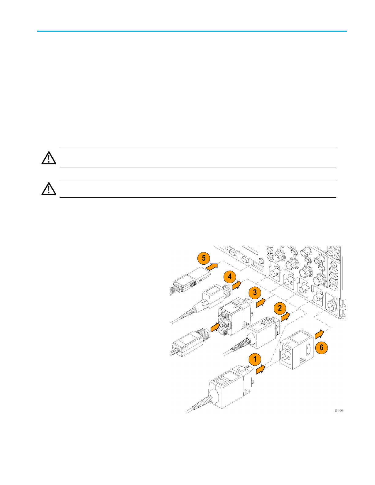
Connecting Probes
The oscilloscope supports probes with the following:
1. Tektronix Versatile Probe Interface
(TekVPI)
These probes support two-way
communication with the oscilloscope
through on-screen menus and remotely
through programmable support. The
remote control is useful in applications
like ATE where you want the system to
preset probe parameters.
2. Tektronix Versatile Probe Interface
(TekVPI) for Passive Probes
These probes build upon the functionality
of the TekVPI interface. Each probe
is matched with its corresponding
oscilloscope channel, allowing the
oscilloscope to optimize the signal input
path. This provides AC compensation
across the frequency band.
MDO3000 Series Oscilloscopes User Manual 7
Page 30

Installation
3. TPA-BNC Adapter
The TPA-BNC Adapter allows you to
use TEKPROBE I
such as providing probe power, and
passing scaling and unit information to
the oscillos
I probe capabilities,
cope.
Securi
4. BNC Interfa
Some of these use TEKPROBE
capabilities to pass the waveform signal
and scaling
only pass the signal and there is no other
communication.
5. Logic Probe Interface
The P6316 p
of digital (on or off state) information.
6. The TPA-N
use TekVPI probes in the RF input.
For more information on the many probes available for use with MDO3000 Series oscilloscopes, visit the Oscilloscope Probe
and Accessory Selector Tool on the Tektronix website at www.tektronix.com.
ces
to the oscilloscope. Some
robe provides 16 channels
-VPI Adapter allows you to
ng the Oscilloscope
1. Use a st
security lock to secure your oscilloscope
to your location.
andard laptop computer style
8 MDO3000 Series Oscilloscopes User Manual
Page 31

Powering on the Oscilloscope
Ground the Oscilloscope and Yourself
To power on the instrument, connect the power cord that was provided with the instrument to the power connector on the
rear panel. C
power cord from the instrument.
onnect the power cord to a properly grounded electrical outlet. To power off the instrument, remove the
Installation
Grounding th
same ground as any circuits that you are testing.
If you are wo
components, ground yourself. Static
electricity that builds up on your body
can damage
Wearing a grounding strap safely sends
static charges on your body to earth ground.
To connect the power cord and power on the oscilloscope:
1. Connect the supplied power cord to the rear-panel power connector.
2. Push the power button on the instrument front-panel and the instrument will turn on.
NOTE. The Standby button on the front-panel does not disconnect mains power. Only the power cord at the rear of the
produc
e oscilloscope is necessary for safety and to take accurate measurements. The oscilloscope needs to share the
rkingwithstaticsensitive
static-sensitive components.
t can disconnect mains power.
MDO3000 Series Oscilloscopes User Manual 9
Page 32

Installation
Powering off the Oscilloscope
To power off the oscilloscope and remove the power cord:
1. Push the power button on the instrument front-panel to turn the instrument off.
2. If you want to remove power completely, disconnect the power cord from the rear-panel of the instrument.
Functional Check
Perform this quick functional check to verify that your oscilloscope is operating correctly.
1. Connect the oscilloscope power cable
as described in Powering On the
Oscilloscope. (See page 9.)
2. Power on the oscilloscope.
10 MDO3000 Series Oscilloscopes User Manual
Page 33

3. Connect the probe connector to
oscilloscope channel 1 and the probe tip
and reference
terminals on the oscilloscope front panel.
4. Push Default Setup.
5. Push Autoset. The screen should now
display a square wave, approximately
2.5 V at 1 kHz.
If the signal appears but is misshapen,
perform the procedures for compensating
the probe.
If no signal appears, rerun the procedure.
If this does not remedy the situation,
have the instrument serviced by qualified
service personnel.
lead to the PROBE COMP
Installation
Compensating a TPP0250, TPP0500B or TPP1000 Passive Voltage Probe
The MDO3000 Series oscilloscopes can automatically compensate T PP0250, TPP0500B and TPP1000 probes. This
eliminates the need for manual probe compensation, as is typically performed with other probes.
Each compensation generates values for a specific probe and channel combination. If you want to use the probe on another
channel and desire to compensate the new probe-channel pair, you must run a new set of compensation steps for that new
ination.
comb
1. Connect the oscilloscope power cable. (See
9, Powering on the Oscilloscope.)
page
2. Power on the oscilloscope.
MDO3000 Series Oscilloscopes User Manual 11
Page 34

Installation
3. Connect the probe connector to the
oscilloscope channel, and the probe tip
and reference
lead to the PROBE COMP
terminals on the oscilloscope front panel.
NOTE. Connect only one probe at a time to the
probe comp te
rminals.
4. Push a front panel button for an input
channel connected to the probe you wish to
compensat
e. (1, 2, 3,or4)
5. Notice on the lower menu that the
cope has automatically set the probe
oscillos
termination value
6. Push Mor
e repeatedly to select Probe
Setup from the resulting pop-up menu.
Coupling
DC|AC
Termina-
tion set b
TPP1000
Invert
y
On |
Off
Bandwidth
Full
Label
More
12 MDO3000 Series Oscilloscopes User Manual
Page 35

TPP1000
Probe
Setup
SN:
000001
Atten: 10X
7. Notice that the compensation status starts
as Default.
8. Push Compens
ate probe and follow the
instructions that appear on the display.
Compen-
sation
Status
Default
Compen-
sate probe
for 1
Measure
Current
Yes |
No
When compensating TPP0250/TPP0500B/TPP1000 probes on the MDO3000 S eries oscilloscopes:
Each compensation generates values for a specific probe and channel combination. If you want to use the probe on
another channel and desire to compensate the new probe-channel pair, you must run a new set of compensation steps.
Installation
Each channel can store compensation values for 10 individual probes. If you try to compensate an 11th p robe on a
channel, the oscilloscope will delete the values for the least recently used probe and add the values for the new probe.
The oscilloscope w
ill assign default compensation values to a TPP0250, TPP0500B or TPP1000 probe connected to
the Aux In channel.
NOTE. A factory calibration will delete all stored compensation values
NOTE. A probe com
pensation failure is most likely due to intermittent connection of the probe tip or ground connection
during the probe compensation operation. If a failure occurs, the oscilloscope will re-use the old probe compensation values,
if they existed prior to the failed probe compensation operation.
Compensating a non-TPP0250, non-TPP0500B or non-TPP1000 Passive
Voltage Probe
Whenever you attach a passive voltage probe for the first time to any input channel, compensate the probe to match it to
the corresponding oscilloscope input channel.
If you are interested in using the automatic probe compensation procedure described above for the TPP0250, TPP0500
and TPP1000 probes (See page 11, Compensating a TPP0250, TPP0500B or TPP1000 Passive Voltage Probe.). On a
non-TPP0250/TPP0500B/TPP1000 Tektronix passive probe, check the instruction manual for your probe to see if it qualifies.
Otherwise, to properly compensate your passive probe:
1. Follow the steps for the functional
check. (See page 10, Functional
Check.)
MDO3000 Series Oscilloscopes User Manual 13
Page 36

Installation
2. Check the shape of the displayed
waveform to determine if your
probe is prope
rly compensated.
Properly compensated
Under compensa
ted
Over compensat
ed
3. If necessary,
Repeat as needed.
adjust your probe.
Quick Tips
Use the shortest possible ground lead
and signal path to minimize probe-induced
ringing a
signal.
nd distortion on the measured
Signal with a short ground lead
ithalonggroundlead
Signal w
Application Module Free Trial
A 30-day free trial is available for all application m odule licenses not installed in your oscilloscope. The trial period begins
when you power on the oscilloscope for the first time.
After 30 days, you must purchase the module if you want to continue using the application. To see the date when your
free trial period expires, push Utility on the front panel, push Utility Page on the lower menu, turn the Multipurpose a
knob to select Config, and push About on the lower menu.
Installing an Application M odule
CAUTION. To avoid damage to the oscilloscope or application module, observe ESD (electrostatic discharge) precautions.
(See page 9, Powering on the Oscilloscope.)
Turn off the oscilloscope power while removing or adding an application module.
(See page 10, Powering off the Oscilloscope.)
14 MDO3000 Series Oscilloscopes User Manual
Page 37

Installation
Optional application module packages extend the capability of your oscilloscope.
You can physically install up to two application modules at one time. Application modules can go into the slots with a window
in the upper right corner of the front panel. One additional slot is directly behind the one that you can see. To use the hidden
slot, install the module with the label facing away from y ou.
Some of the modules have licenses that allow you to transfer the license between your application modules and the
oscilloscope. You can keep each license in the module, which will allow you to move the module from one instrument to
another. Alternatively, you can move the license from the module to the oscilloscope. This approach will allow you to store
the module separately from the oscilloscope for safe keeping. This approach will also allow you to use more than two
applications on your oscilloscope simultaneously. To transfer a license from a module to your oscilloscope or from your
oscilloscope to a module:
1. Turn off the power to the oscilloscope. Insert the application modules into the oscilloscope. Turn on the power.
2. Push Utility on the front panel. If needed, push Utility Page on the lower menu and turn the Multipurpose a knob to
select Config. Push Manage Modules and Options on the lower menu, and then push License Type on the side menu
until “Modules” is selected. The licenses contained in the oscilloscope will be listed in the side menu. Push the button
next to the appropriate license to transfer. You may transfer up to two licenses at one time.
3. After you turn off the power to the oscilloscope, you can remove the physical application module from the oscilloscope.
Refer to the MDO3000 Series Oscilloscopes Application Module Installation Manual that came with your application module
for instructions on installing and testing an application module.
NOTE. If you transfer a license from a module to an oscilloscope, the module will not work on another oscilloscope until
you transfer the license back from the oscilloscope to the module. Consider putting the physical module in an envelope
or other storage with a label recording the date, module name, model and serial number of the oscilloscope which holds
the license. This will help prevent confusion later if someone finds the module, installs it in some other oscilloscope,
and wonders why it does not work.
Upgrading Bandwidth
You may increase the bandwidth of an instrument when
by purchasing an upgrade.
1 GHz upgrades require Tek Service installation and option IFC (calibration).
Model to be upgraded Bandwidth before
MDO3012
your project requirements demand higher performance. Do this
Bandwidth after
upgrade
100 MHz 200 MHz
100 MHz 350 MHz
100 MHz 500 MHz
100 MHz
upgrade
1 GHz MDO3BW1T102
Order this product
MDO3BW1T22
MDO3BW1T32
MDO3BW1T52
200 MHz 350 MHz
200 MHz 500 MHz
MDO3000 Series Oscilloscopes User Manual 15
MDO3BW2T32
MDO3BW2T52
Page 38

Installation
MDO3014
200 MHz
350 MHz 500 MHz
350 MHz
500 MHz
100 MHz 200 MHz
100 MHz 350 MHz
100 MHz 500 MHz
100 MHz
200 MHz 350 MHz
200 MHz 500 MHz
z
200 MH
Hz
350 M
1 GHz MDO3BW2T102
1 GHz MDO3BW3T102
1 GHz MDO3BW5T102
1 GHz MDO3BW1T104
1 GHz MDO3BW2T104
Hz
500 M
MDO3BW3T52
MDO3BW1T24
MDO3BW1T34
MDO3BW1T54
MDO3BW2T34
MDO3BW2T54
MDO3BW3T54
MDO3022
MDO3024
MHz
350
MHz
500
0MHz
20
00 MHz
2
00 MHz
2
350 MHz 500 MHz
350 MHz
500 MHz
200 MHz 350 MHz
200 MHz 500 MHz
200 MHz
350 MHz 500 MHz
1 GHz MDO3BW3T104
1 GHz MDO3BW5T104
0MHz
35
00 MHz
5
1 GHz MDO3BW2T102
1 GHz MDO3BW3T102
1 GHz MDO3BW5T102
1 GHz MDO3BW2T104
MDO3BW2T32
MDO3BW2T52
MDO3BW3T52
MDO3BW2T34
MDO3BW2T54
MDO3BW3T54
350 MHz
16 MDO3000 Series Oscilloscopes User Manual
1 GHz MDO3BW3T104
Page 39

Installation
MDO3032
MDO3034
MDO3052
MDO3054
500 MHz
350 MHz 500 MHz
350 MHz
500 MHz
350 MHz 500 MHz
350 MHz
500 MHz
500 MHz
500 MHz
1 GHz MDO3BW5T104
MDO3BW3T52
1 GHz MDO3BW3T102
1 GHz MDO3BW5T102
MDO3BW3T54
1 GHz MDO3BW3T104
1 GHz MDO3BW5T104
1 GHz MDO3BW5T102
1 GHz MDO3BW5T104
To enable the upgrade, you will need to order a bandwidth upgrade product. 1 GHz upgrades require you to send your
instrument to a Tektronix Service Center. All others can be performed in the field by the customer.
You will need to supply the model number and serial number when placing your order. To determine the serial number of
nstrument, push Utility, and then push About. The serial number is located on the resulting screen.
your i
rade bandwidth by installing an option key on your instrument,
To upg
1. Once you have placed an order for the
appropriate bandwidth upgrade product, you
ld receive an Option Key Certificate.
shou
with the option key number.
2. Push Utility.
3. On the lower menu, push Utility Page and
elect Config.
s
4. Push Manage Modules & Options.
Utility Page
Config
Manage
Modules &
ptions
O
MDO3000 Series Oscilloscopes User Manual 17
Page 40

Installation
5. On the side menu, push License Type until
Options is highlighted.
6. Push Install Option.
7. Enter the Option Key number by turning
Multipurpo
se a and pushing Enter
Character on the lower menu. Alternatively,
you may use a USB keyboard.
8. Push OK Accept on the side menu.
Following a successful installation of the
option ke
y, a message will be displayed
indicating that you must power cycle the
oscilloscope to enable the new features.
License
Type
Modules
Options
Install
Option
Enter
Character
OK
Accept
Chan
9. Power cy
10. To verify that the bandwidth has been
upgrad
cle the oscilloscope.
About
ed, push Utility, and then push
About on the lower menu. The bandwidth
information should be towards the top of this
n.
scree
ging the Language of the User Interface or Keyboard
To change the language of the oscilloscope user interface or keyboard, and to change the front panel button labels through
the use of an overlay:
1. Push Utility.
18 MDO3000 Series Oscilloscopes User Manual
Page 41
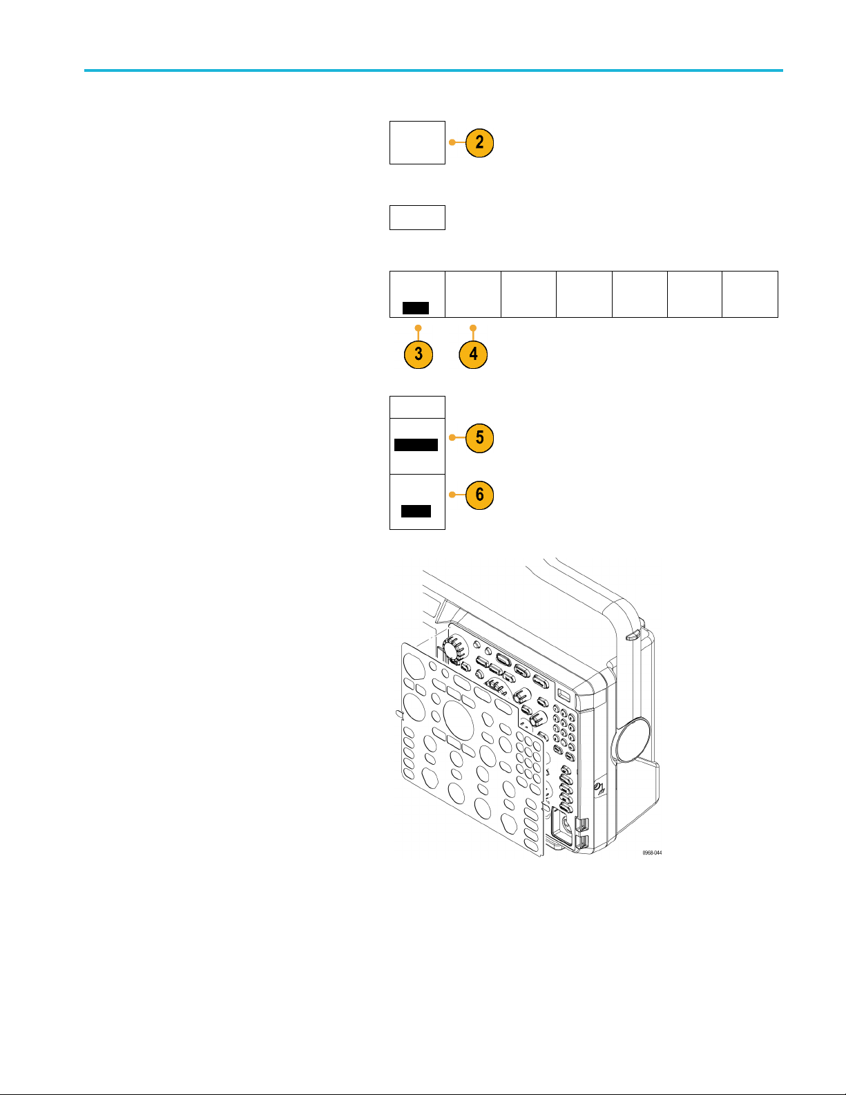
Installation
2. Push Utility P
age.
3. Turn Multipurpose a and select Config.
4. Push Langua
ge from the resulting lower
menu.
5. Push Menus from the resulting side menu
and turn
Multipurpose a to select the
desired language for the user interface.
6. Push USB
Keyboard from the resulting side
menu and turn Multipurpose a to select the
desired language version of keyboard to use.
Utility
Page
Config
Utility
Page
Config
Language
Menus
(a) English
USB
Keyboard
Englis
h
Language
Set Date &
Time
About Manage
Modules &
Options
7. If you choose to use an English user
interface, be sure that the plastic front panel
ay is removed.
overl
If you choose a language other than English,
place the plastic overlay for the language
you desire over the front panel to display
that
labels in that language.
MDO3000 Series Oscilloscopes User Manual 19
Page 42

Installation
Changing the Date and Time
To set the internal clock with the current date and time:
1. Push Utility.
2. Push Utilit
y Page.
3. Turn Multipurp ose a and select Config.
4. Push Set
5. Push th
Date & Time.
e side menu buttons and turn both
the (Multipurpose a and Multipurpose b)
knobs to set the time and date values.
6. Push
OK Set Date & Time.
Utility
Page
Config
Utility
Page
Config
Displa
Date &
Time
On|Of
Hour
4
Minut
44
Month
May
Day
3
Year
2011
OK Set
Date &
Time
e
y
f
Language
Set Date &
Time
About Manage
Modules &
Options
20 MDO3000 Series Oscilloscopes User Manual
Page 43

Signal Path Compensation
Signal Path Compensation (SPC) corrects for DC inaccuracies caused by temperature variations and/or long-term drift.
Run the compensation whenever the ambient temperature has changed by more than 10 °C (18 °F) or once a week
if you use vertical settings of 5 mV/division or less. Failure to do so may result in the instrument not meeting warranted
performance levels at those volts/div settings.
Signal Path Compensation for Time and Frequency Domains
To compensate the signal path:
1. Warm up the oscilloscope for at least
20 minutes. Remove all input signals
(probes and cables) from channel inputs.
Input signals with AC components adversely
affect SPC.
Installation
2. Push Utility.
3. Push Utility Page.
4. Turn Multipurpose a and select
Calibration.
5. Push Signal Path on the lower menu.
Utility
Page
Calibration
Utility
Page
Calibration
Signal
Path
Pass
Factory
Pass
MDO3000 Series Oscilloscopes User Manual 21
Page 44
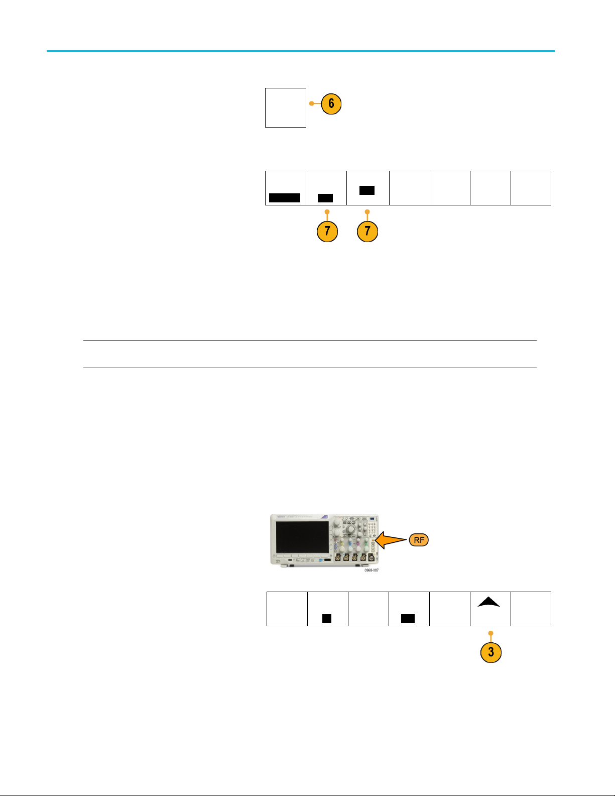
Installation
6. Push OK Compensate Signal Paths on
the resulting side menu.
The calibrati
on will take approximately
OK Com-
pensate
Signal
Paths
10 minutes to complete.
7. After calibr
ation, v e rify that the status
indicator on the lower menu displays Pass.
Utility
Page
Calibration
Signal
Path
Pass
Factory
Pass
If it does not, then recalibrate the instrument
or have the i
nstrument serviced by qualified
service personnel.
Service pe
rsonnel use the factory calibration
functions to calibrate the internal voltage
references of the oscilloscope using
external s
ources. Contact your Tektronix
field office or representative for assistance
with factory calibration.
NOTE. Signal Path Compensation does not include calibration to the probe tip. (See page 13, Compensating a
non-TPP0
250, non-TPP0500B or non-TPP1000 Passive Voltage Probe.)
Signal Path Compensation for Frequency Domain Only
The signal path compensation (SPC) described above runs on both the time and the frequency domain inputs. If you only
want to compensate the RF input, you can save time by running SPC only on the RF input and skipping the time domain
part. You can do this as follows:
1. As with the time and frequency calibration,
warm up the oscilloscope for at least
20 minutes. Remove all input signals
(probes and cables) from the RF input.
2. Push RF to bring up the Frequency Domain
menu.
3. Push More to select Compensate Signal
Path.
4. On the resulting side menu, push OK.
Compensate RF Signal Path.
Spectrum
Traces
Spectro-
gram
On
Spectrum
Triggered
Detection
Method
Auto
Edit Labels
More
22 MDO3000 Series Oscilloscopes User Manual
Page 45

Upgrading Firmware
To upgrade the firmware of the oscilloscope:
1. Open up a Web browser and go to
www.tektronix.com/software/downloads.
Proceed to the software finder. Download
the latest firmware for your oscilloscope on
your PC.
Unzip the files and copy the firmware.img
file into th
or USB hard drive.
e root folder of a USB flash drive
Installation
2. Power off y
3. Insert the USB flash or hard drive into
the USB port on the front panel of your
oscil
our oscilloscope.
loscope.
MDO3000 Series Oscilloscopes User Manual 23
Page 46

Installation
4. Power on the osc
automatically recognizes the replacement
firmware and installs it.
If the instrum
firmware, rerun the procedure. If the
problem continues, try a d ifferent model of
USB flash or ha
contact qualified service personnel.
NOTE. Do not power off the oscilloscope or
remove the US
finishes installing the firmware.
5. Power off the oscilloscope and remove the
USB flash or hard drive.
illoscope. The instrument
ent does not install the
rd drive. Finally, if needed,
B drive until the o scilloscope
6. Power on the oscilloscope.
7. Push
Utility.
24 MDO3000 Series Oscilloscopes User Manual
Page 47

Installation
8. Push Utility P
age.
9. Turn Multipurpose a and select Config.
10. Push About. The oscilloscope displays the
firmware ve
11. Confirm tha
rsion number.
t the version number matches
that of the new firmware.
Utility
Page
Config
Utility
Page
Config
Language
Set Date &
Time
About Manage
Modules &
Options
MDO3000 Series Oscilloscopes User Manual 25
Page 48

Installation
Connecting Your Oscilloscope to a Computer
Connect your oscilloscope directly to a computer to let the PC analyze your data, collect screen images, or to control your
oscilloscope. (See page 164, Saving a Screen Image.) (See page 165, Saving and Recalling Waveform and Trace D ata.)
Three ways to connect your oscilloscope to a computer are through the VISA drivers, the e*Scope Web-enabled tools, and a
socket server. Use VISA to communicate with your oscilloscope from your computer through a software application, such as
Tektronix OpenChoice Desktop®. Use e*Scope to communicate with your oscilloscope through a Web browser, such as
Microsoft Internet Explorer. For best results, use a browser that supports html 5.
Using VISA
VISA lets yo
runs on your PC, such as Microsoft Excel, National Instruments LabVIEW, Tektronix OpenChoice Desktop software, or a
program of your own creation. You can use a common com munications connection, such as USB, Ethernet, or GPIB,
to connect
For VISA,
the drivers and OpenChoice Desktop software on the appropriate CD that comes with your oscilloscope or at the Tektronix
software finder Web page (www.tektronix.com).
Using e*
With e*Scope, you can access and control any Internet-connected MDO3000 Series oscilloscope from a web browser
on your computer.
Connect the oscilloscope to your network using the LAN port. The built-in LXI web interface (Core 2011, Version 1.4)
provides network configuration information, which you can edit and customize. It also provides remote instrument control
through the e*Scope user interface. There you can control instrument settings, save screen images, save instrument data or
setups, and much more. Do all this throug h a password-protectable web-interface.
To set up VISA communications between your oscilloscope and a computer:
1. Load the VISA drivers on your computer.
u use your MS-Windows computer to acquire data from your oscilloscope for use in an analysis package that
the computer to the oscilloscope.
load the VISA drivers on your computer. Also, load your application, such as OpenChoice Desktop. You will find
Scope
Also, load your application, such as
OpenChoice Desktop.
You will find the drivers and OpenChoice
Desktop software on the appropriate CD
that comes with your oscilloscope or at
the Tektronix software finder Web page
(www.tektronix.com).
26 MDO3000 Series Oscilloscopes User Manual
Page 49

2. Connect the oscilloscope to your computer
with the appropriate USB or Ethernet cable.
To communicate between the oscilloscope
and a GPIB system, connect the oscilloscope
to the TEK-USB-488 GPIB-to-USB Adapter
with a USB cable. Then connect the adapter
to your GPIB system with a GPIB cable.
Cycle the power on the oscilloscope.
Installation
3. Push Utility.
4. Push Utility Page.
5. Turn Multipu rpo se a and select I/O.
6. If you are using USB, the system sets itself
up automatically for you, if USB is enabled.
Check USB on the lower menu to be sure
t USB is enabled. If it is not enabled, push
tha
USB. Then push Connect to Computer on
the side menu.
Utility
Page
I/O
Uti
Page
I/O
lity
Co
USB
mputer
Ethernet &
LXI
work
Net
Configura-
tion
tomatic
Au
Socket
ver
Ser
GPIB
1
MDO3000 Series Oscilloscopes User Manual 27
Page 50

Installation
7. To use Ethernet, push Ethernet & LXI on
the lower menu.
Use the side me
nu buttons to adjust
your network settings, as needed. For
more information, see the e*Scope setup
information
below.
8. If you want to change socket server
parameters
, push Socket Server and enter
new values through the resulting side menu.
9. If you are u
sing GPIB, push GPIB. Enter the
GPIB address on the side menu, by turning
the Multipurpose a knob.
This will set the GPIB address on an
attached TEK-USB-488 Adapter.
Talk/Listen
Address
(a) 1
28 MDO3000 Series Oscilloscopes User Manual
Page 51

10. Run your application software on your
computer.
Quick Tips
Your oscilloscope shipped with a CD that contains a variety of Windows-based software tools for efficient connectivity
between your oscilloscope and your computer. These include tool bars that speed connectivity with Microsoft Excel and
Word. There is also a standalone acquisition program called Tektronix OpenChoice Desktop.
The rear-panel USB 2.0 device port is the correct USB port for computer connectivity. Use the rear and front panel USB
2.0 host port to connect your oscilloscope to USB flash drives. Use the USB Device port to connect your oscilloscope
to a PC or a PictBridge printer.
USB Host port
USB Device port
Installation
Using the LXI Web Page and e*Scope
With e*Scope, you can access any Internet-connected M DO 3000 Series oscilloscope from a web browser on your computer
or tablet.
To set up e*Scope communications between your oscilloscope and a Web browser running on a remote computer:
1. Connec
2. Push Utility.
t the oscilloscope to your computer
network with an appropriate Ethernet cable.
MDO3000 Series Oscilloscopes User Manual 29
Page 52

Installation
3. Push Utility P
age.
4. Turn Multipurpose a and select I/O.
5. Push Ether
net & LXI.
6. View the top item on the side menu to
determine the condition of the LAN. An
or turns green for good status and red
indicat
if the device detects a fault.
7. Push LAN
Settings to display the network
parameters configured on your oscilloscope.
Utility
Page
I/O
Utility
Page
I/O
Ethernet
LXI LAN
Status
LAN
Setting
&
s
USB
Computer
Ethernet &
LXI
Network
Configura-
tion
Automatic
Socket
Server
GPIB
1
8. Push LA
N Reset to restore the LAN defaults
to your oscilloscope.
9. Push Te
st Connection to check if your
oscilloscope can find an attached network.
10. Push m
ore to see another page of side
menu items.
LAN Reset
Test Con-
nection
more 1 of 2
30 MDO3000 Series Oscilloscopes User Manual
Page 53

11. Push Change Names to change the name
of the oscillo
scope, the network domain, or
the service name.
12. Push Change E
thernet & LXI Password to
change the name of the password.
13. Push Change
e*Scope Password to use
the LXI password to also protect your
oscilloscope from changes made to LAN
settings fr
om a Web browser.
14. Start your browser on your remote computer.
In the bro
wser address line, enter the host
name, a dot, and the domain name together.
Alternatively, just enter the IP address of
rument. Either way, you should then
the inst
see the LXI Welcome page on your Web
browser on your computer screen.
Ethernet &
LXI
Change
Names
Change
Ethernet
&LXI
Password
Change
e*Scope
Password
a Enabled
more
2of2
Installation
15. Click “Network Configuration” to view and
edit the network configuration settings. If
using a password and changing
you are
your settings, you need to know that the
default user name is “lxiuser”.
MDO3000 Series Oscilloscopes User Manual 31
Page 54

Installation
16. For e*Scope, click the Instrument Control
(e*Scope) link on the left side of the LXI
Welcome page.
tab (or window) open in your browser with
e*Scope running.
You should then see a new
Using a Socket Server
et server provides two-way communication over an Internet Protocol-based computer network. You can use your
Asock
oscilloscope’s socket server feature to l et your oscilloscope communicate with a remote-terminal device or computer.
To set up and use a socket server between your oscilloscope and a remote terminal or computer:
1. Connect the oscilloscope to your computer
ork using an appropriate Ethernet
netw
cable.
32 MDO3000 Series Oscilloscopes User Manual
Page 55

2. Push Utility.
Installation
3. Push Utility Page.
4. Turn Multipu rpo se a and select I/O.
5. Push Socket Server.
6. On the resulting Socket Server side menu,
push the top entry to highlight Enabled.
7. Choose whether the protocol should be
None or Terminal.
A communication session run by a human
at a keyboard typically uses a terminal
protocol. An automated session might
handle its own communications without such
protocol from the oscilloscope.
8. If required, change the port number by
turning Multipurpose a.
9. If required, press OK to set the new port
number.
Utility
Page
I/O
Utility
Page
I/O
Socket
Server
Enabled
Disabled
Protocol
None
Terminal
Current
Port 4000
Select Port
(a) 4000
OK
Set Port
USB
Computer
Ethernet &
LXI
Network
Configura-
tion
Manual
Socket
Server
GPIB
1
MDO3000 Series Oscilloscopes User Manual 33
Page 56

Installation
10. After you have set up the socket server
parameters, the computer is now ready to
communicate w
ith the oscilloscope. If you
are running an MS Windows PC, you could
run its default client Telnet, which has a
command inte
by typing “
rface. One way to do this is
Telnet ” in the Run window.
The Telnet window will open on the PC.
NOTE. On MS Wi
ndows 7, you must first
enable Telnet in order for Telnet to work.
11. Start a terminal session between your
computer and your oscilloscope by typing in
an open com
mand with the oscilloscope's
LAN address and port #.
You can obtain the LAN address by pushing
the Ether
net & LXI lower menu button
and the resulting LAN Settings side menu
button to view the resulting Ethernet and
LXI Setti
ngs screen. You can obtain the port
# by pushing Socket Server on the lower
menu and viewing Current Port on the side
menu.
For example, if the oscilloscope IP address
was
123.45.67.89 and the post #
was the
default of 4000, you could open
a session by writing into the MS Windows
Telnet screen:
illoscope will send a help screen to the
The osc
o 123.45.67.89 4000.
computer when it has finished connecting.
34 MDO3000 Series Oscilloscopes User Manual
Page 57

Installation
12. You can now type
NOTE. Do not use the computer’s backspace
key during a
the oscilloscope.
Connecti
You can connect a USB keyboard to a USB Host port on the rear or front panel of the oscilloscope. The oscilloscope will
detect the keyboard, even if it is plugged in while the oscilloscope is powered on.
You can use the keyboard to quickly create names or labels. You can bring up the Label button on the lower menu by
pushing a Channel or Bus button. Use the arrow keys on the keyboard to move the insertion point, and then type in a name
or label. Labeling channels and buses makes the information on the screen easier to identify.
in a standard query, such
as,
*idn?.
The Telnet session window will respond by
displaying a c
haracter string describing your
instrument.
You can type in more queries and view
more results
using this Telnet session
window. You can find the syntax for relevant
commands, queries and related status
codes in the M
DO3000 Series Programmer
Manual.
n MS Windows Telnet session with
ng a USB Keyboard to Your Oscilloscope
To choose whether to use a keyboard with a United States (US) key layout or one with an alternative layout:
1. Push Utility.
2. Push Utility Page.
Utility
Page
Confi
g
Language
Set Da
Time
te &
About Manage
Modules &
Optio
ns
3. Turn Multipurpose a and select Config.
4. Push Languag e on the lower menu.
5. Push USB Keyboard on the side m enu.
6. Turn Multipurpo se a and select the desired
yboard layout style from the resulting
ke
menu.
MDO3000 Series Oscilloscopes User Manual 35
Page 58

Get Acquainted w
ith the Instrument
Get Acquainte
dwiththeInstrument
Front-Panel Menus, Controls, and Connectors
Overview
The front panel has buttons and controls for the functions that you use most often. Use the menu buttons to access
more specialized functions.
1. Traditional oscilloscope front panel controls
2. 10-digit keypad
3. Application module slots
4. Ground strap connector
5. Ground
6. PROBE COMP
7. Dedicated spectral analysis controls
8. Dedicated RF input with N-connector
9. Analog channel (1, 2, (3, 4)) inputs with TekVPI versatile probe interface
10. Digital channel input
11. Display: shows frequency or time domain
12. Arbitrary function generator (AFG) enable button
36 MDO3000 Series Oscilloscopes User Manual
Page 59

Front Panel Menus and Controls
The front panel has buttons and controls for the functions that you use most often. Use the menu buttons to access
more specialized functions.
Using the Menu System
To use the menu system:
1. Push a front panel menu button to
display the menu that you want to use.
NOTE. The B1 and B2 buttons support up
to two different serial or parallel buses.
Get Acquainted w
ith the Instrument
2. Push a lower menu button. If a pop-out
menu ap
select the desired choice. If a pop-up
menu appears, push the button again to
selec
3. Push a side menu button.
If the
choice, push the side button repeatedly
to cycle through the choices.
If a p
Multipurpose a to select the desired
choice.
pears, turn Multipurpose a to
t the desired choice.
menu item contains more than one
op-out menu appears, turn
MDO3000 Series Oscilloscopes User Manual 37
Page 60

Get Acquainted w
ith the Instrument
4. Toremoveaside
button again or push Menu Off.
5. Certain menu choices require you to
set a numeric value to complete the
setup. You ca
multipurpose knobs a and b to adjust
values. You can also set many numerical
values with
front panel.
6. Push Fine to turn off or on the ability to
make smaller adjustments.
menu, push the lower
n use the upper and lower
the 10-digit keypad on the
Using the Menu Buttons
Use the me
nu buttons to perform many functions in the oscilloscope.
1. Measure. Push to perform automated measurements on waveforms and to access the digital voltmeter (DVM) and
waveform histogram functions.
2. Search. Push to perform an automated
3. Autoset. Push to perform an automatic setup of oscilloscope settings.
4. Test. Push to activate advanced or application-specific testing features.
38 MDO3000 Series Oscilloscopes User Manual
search through an acquisition for user-defined events/criteria.
Page 61

Get Acquainted w
5. Acquire. Push to set the acquisition mode and adjust the record length.
6. Trigger Menu. Push to specify trigger s ettings.
7. M. Push to manage the math waveform, including the display or removal of the math waveform from the display.
8. R. Push to manage reference waveforms, including the display or removal of each reference waveform from the display.
9. B1 or B2. Pushtodefine and display a serial bus if you have the appropriate application modules. Parallel bus support
is available
remove the corresponding bus from the display.
10. AFG. Push to enable the arbitrary function generator output and access the AFG menu.
11. Vertical Position. Turn to adjust the vertical position of the corresponding waveform. Push to center the waveform
baseline indicator.
12. Channel 1, 2, 3,or4Menu. Push to set vertical parameters for input waveforms and to display or remove the
correspon
on MDO3000 products with the MDO3MSO option installed. Also, push the B1 or B2 button to display or
ding waveform from the display.
ith the Instrument
13. Vertical S
front-panel Fine button to make smaller adjustments.
cale. Turn to adjust the vertical scale factor of the corresponding waveform (volts/division). Push the
Below the display buttons
Use the buttons below the display to perform many functions in the oscilloscope.
1. Save / Re
Save button to save and recall setups,
waveforms, or screen images to internal
memory,
network drive.
2. Default Setup. Push to perform an
immed
the default settings.
call Menu.Pushtodefine the
aUSBflash drive, or a mounted
iate restore of the oscilloscope to
3. Utility. Push to activate the system utility
functions, such as selecting a language
or setting the date/time.
MDO3000 Series Oscilloscopes User Manual 39
Page 62

Get Acquainted w
4. B1 or B2. Pushtodefine and display a
bus if you have the appropriate module
application k
ith the Instrument
eys.
MDO3AERO supp
and MIL-STD-1553 buses.
MDO3AUDIO supports I2S, Left
Justified (LJ), Right Justified (RJ),
and TDM buses
MDO3AUTO su
FD, and LIN buses.
MDO3EMBD supports I2C and SPI
buses.
MDO3COMP supports RS-232,
RS-422, RS
MDO3FLEX s
MDO3USB s
Also, push the B1 or B2 button to display
or remov
the display.
5. R. Push to manage reference waveforms
and traces, including the display or
remova
trace from the display.
e the corresponding bus from
l of each reference waveform or
orts ARINC429
.
pports CAN, CAN
-485, and UART buses.
upports FlexRay buses.
upports USB 2.0 buses.
6. M. Push to manage the math waveform
or trace, including the display or removal
math waveform or trace from the
of the
display.
40 MDO3000 Series Oscilloscopes User Manual
Page 63

Using Spectral Analysis Controls
These buttons configure the acquisition and display of the RF input.
Get Acquainted w
ith the Instrument
1. RF.Pushtobri
domain display and menu. The RF menu
provides access to the Spectrogram
display.
2. Freq/Span.
of the spectrum to view on the display.
Set the center frequency and the span –
or set the st
3. Ampl. Push
4. BW. Push t
bandwidth.
5. Markers.
manual markers.
ng up the frequency
Push to specify the portion
art and stop frequency.
to set the reference level.
odefine the resolution
Push to set automatic or
Using Other Controls
1. Cursors. Push once to activate the two vertical cursors. Push again to turn off all cursors. Push and hold to bring up the
cursor menu. Use the menu to select the cursor features, such as type, source, orientation, linked status, and units.
When the cursors are on, you can turn the multipurpose knobs to control their position.
2. Turn the upper multipurpose knob a, when activated, to move a cursor, to set a numerical parameter value for a menu
item, or to select from a pop-out list of choices. Push the Fine button to toggle between coarse and fine adjustment.
Screen icons tell you when a or b are active.
3. Select. Push to activate special functions.
MDO3000 Series Oscilloscopes User Manual 41
Page 64

Get Acquainted w
For example, when using the two vertical cursors (and no horizontal ones are visible), you can push this button to link or
unlink the curs
either the vertical c ursors or the horizontal cursors active.
4. Fine. Push to toggle between making coarse and fine adjustments with the many operations of multipurpose knobs a
and b
5. Turn the lower Multipurpose b knob, when activated, to move a cursor or set a numerical parameter value for a
menu item. Pu
ith the Instrument
ors. When the two vertical and two horizontal cursors are both visible, you can push this button to make
sh Fine to make adjustments more slowly.
6. Intensity.P
7. Zoom button. Push to activate zoom mode.
8. Pan (outer knob). Turn to scroll the zoom window through the acquired waveform.
9. Zoom-scale (inner knob). Turn to control the zoom factor. Turning it clockwise zooms in further. Turning it
counterclockwise zooms out.
10. Play-pause button. Push to start or stop the automatic panning of a waveform. Control the speed and direction with
the pan knob.
ush to enable Multipurpose a to control waveform display intensity and knob b to control graticule intensity.
11. ← Prev. Push to jump to the previous waveform mark.
12. Set/Clear Mark. Push to establish or delete a waveform mark.
13. → Next. Push to jump to the next waveform mark.
42 MDO3000 Series Oscilloscopes User Manual
Page 65

Get Acquainted w
ith the Instrument
14. Horizontal Position. Turn to adjust the trigger point location relative to the acquired w aveforms. Push to center
when delay is on
. Push to set to 10% when delay is off.
15. Horizontal Sc
ale. Turn to adjust the horizontal scale (time/division).
16. Autoset. Push to automatically set the vertical, horizontal, and trigger controls for a usable, stable display.
17. Single. Push to make a single sequence acquisition.
18. Run/Stop . Push to start or stop acquisitions.
19. Trigger Level. Turn to adjust the trigger level.
Push Level to Set 50%. Push the Trigger level knob to set the trigger level to the midpoint of the waveform.
20. Force Trig. Push to force an immediate trigger event.
MDO3000 Series Oscilloscopes User Manual 43
Page 66

Get Acquainted w
ith the Instrument
21. Print. Push to print to the selected printer.
22. Power switch. Push to power on or off the oscilloscope.
23. USB 2.0 Host port. Insert a USB peripheral to the oscilloscope, such as a keyboard or a flash drive.
24. Save. Push to perform an immediate save operation. The save operation uses the current save parameters, as defined
ave / Recall menu.
in the S
25. Save / R
ecall Menu. Push to save and recall setups, waveforms, and screen images to internal memory, or a USB
flash drive.
26. Default Setup. Push to perform an immediate restore of the oscilloscope to the default settings.
27. Utility. Push to activate the system utility functions, such as selecting a language or setting the date/time.
28. D15 - D0. Push to display or remove the digital channels from the display, and to access the digital channel setup
menu (with option MDO3MSO only).
29. Menu Off. Push to clear a displayed menu from the screen.
44 MDO3000 Series Oscilloscopes User Manual
Page 67

Get Acquainted w
ith the Instrument
Identifying Items in the Time Domain Display
The items shown in the graphic below may appear in the display. Not all of these items are visible at any given time. Some
readouts move outside the graticule area when menus are turned off.
1. The acquisition readout shows when an acquisition is running, stopped, or when acquisition preview is in effect. Run =
acquisitions enabled. Stop = Acquisitions not enabled. Roll = roll mode (40 ms/div or slower). PreVu = The oscilloscope
is stopped or between triggers. You can change the horizontal or vertical position or scale to see approximately what the
next acquisition will look like. A/B = When using the average acquisition mode, B shows the total number of acquisitions to
be averaged (set this using the Acquisition Mode side menu), and A shows the current progress towards this total number.
2. The trigger position icon shows the trigger position in the acquisition.
3. The expansion point icon (an orange triangle) shows the point that the horizontal scale expands and compresses around.
To make the expansion point the same as the trigger point, push Acq uir e and set the lower menu Delay item to Off.
MDO3000 Series Oscilloscopes User Manual 45
Page 68

Get Acquainted w
ith the Instrument
4. The waveform
record view shows the trigger location relative to the waveform record. The line color corresponds to the
selected waveform color. The brackets show the part of the record currently displayed on the screen.
5. The trigger status readout shows trigger status. Status conditions are: PrTrig: Acquiring pretrigger data. Trig? = Waiting
for trigger. Trig’d: Triggered. Auto: Acquiring untriggered data.
6. The security icon indicates w hen the I/O ports are disabled.
7. The cursor readout shows time, amplitude, and delta () values for each cursor. For FFT measurements, it shows
frequency and magnitude. For serial and parallel buses, the readout shows the decoded values.
8. The trigger level icon shows the trigger level on the waveform. The icon color corresponds to the trigger source color.
9. The trigger readout shows the trigger source, slope, and level. The trigger readouts for other trigger types show other
parameters.
10. The top line of the record length/sampling rate readout shows the sampling rate. You can adjust it with the Horizontal
Scale knob. The bottom line shows the record length. You can adjust it by pushing Acquire and Record Length
on the lower menu.
46 MDO3000 Series Oscilloscopes User Manual
Page 69

Get Acquainted w
11. The horizontal position/scale readout shows on the top line the horizontal scale (adjust with the Horizontal Scale knob).
With Delay Mode on, the bottom line shows the time from the T symbol to the expansion point icon (adjust with the
Horizontal Position knob). Use horizontal position to insert added delay between when the trigger occurs and when you
actually capture the data. Insert a negative time to capture more pretrigger information. With Delay Mode off, the bottom
line shows the time location of the trigger within the acquisition, as a percentage.
12. The Timing Resolution readout shows the timing resolution of the digital channels. Timing resolution is the time between
samples. It is the reciprocal of the digital sample rate. When the MagniVu control is on, “MagniVu” appears in the readout.
ith the Instrument
13. Measurement readouts show the selected measurements. You can select up to four measurements to display at one
time. A
the waveform is above or below the display. To obtain a proper numerical measurement, turn the vertical scale and
position knobs to make all of the waveform appear in the display.
14. The auxiliary waveform readouts show the vertical and horizontal scale factors of the math and reference waveforms.
15. The channel readout shows the channel scale factor (per division), coupling, invert, and bandwidth status. Adjust with the
Vertical Scale knob and in the channel 1, 2, 3,or4 menus.
symbol appears instead of the expected numerical measurement if a vertical clipping condition exists. Part of
16. For digital channels, the baseline indicators point to the high and low levels. The indicator colors follow the color code
used on resistors. The D0 indicator is black, the D1 indicator is brown, the D2 indicator is red, and so on.
MDO3000 Series Oscilloscopes User Manual 47
Page 70

Get Acquainted w
17. The group icon indicates when digital channels are grouped.
18. The bus display shows decoded packet level information for serial buses or for parallel buses. The bus indicator
shows the bus number and bus type.
19. For analog channels, the waveform baseline indicator shows the zero-volt level of a waveform, assuming you have not
used any offset. The icon colors correspond to the waveform colors.
ith the Instrument
Identifying Items in the Frequency Domain Display
Activate the frequency domain display by pressing the front panel RF button.
48 MDO3000 Series Oscilloscopes User Manual
Page 71

1. Vertical graticule labels
Get Acquainted w
ith the Instrument
2. Start frequency
3. Reference level
4. Vertical scale
5. Center frequency
6. Span and resolution bandwidth
7. Stop frequency
8. Reference marker
MDO3000 Series Oscilloscopes User Manual 49
Page 72

Get Acquainted w
Identifying Items in the Arbitrary Function Generator Display
ith the Instrument
1. If visible, the output is on
2. AFG label
3. Waveform type, e.g. “Sine”
4. Additive Noise icon
5. Frequency
6. Amplitude
(See page 185, Use the Arbitrary Function Generator.)
50 MDO3000 Series Oscilloscopes User Manual
Page 73

Identifying Items in the Digital Voltmeter Display
1. Measurement type (AC+DC RMS, DC, AC RMS, or Frequency)
2. Numerical value of the current measurement
3. Graphic (min, max, value, five-second rolling range)
Get Acquainted w
ith the Instrument
The number on the left side of the graphic’s linear scale is the minimum value of the range (e.g. 0.000 V).
The number on the right side of the graphic’s linear scale i s the maximum value of the range (e.g. 400.0 mV).
The gray bar shows the five second rolling average of measurements.
The inverted triangle shows the location on the scale of the current measurement value.
4. Minimum measurement value recorded since you powered on the instrument or since you last pushed the Reset
DVM Sta
5. Maxim
DVM Statistics menu item.
6. Average of all measurement values recorded since you powered on the instrument or since you last pushed the Reset
DVM Statistics menu item.
7. Frequency
NOTE
appears for voltage measurements ≤ 10 Hz. A “?” message appears next to min or max measurements that have gone
out of bounds. Push Reset DVM Statistics to remove the “?” from the display.
e page 133, Taking Digital Voltmeter Measurements .).
(Se
tistics menu item.
um measurement value recorded since you powered on the instrument or since you last pushed the Reset
. An “Over bandwidth” message appears for voltage measurements ≥ 10 kHz. An “Under bandwidth” message
MDO3000 Series Oscilloscopes User Manual 51
Page 74

Get Acquainted w
ith the Instrument
Front Panel Connectors
1. Logic Probe Co
2. Channel 1, 2, 3
TekVPI Versatile Probe Interface.
3. RF input connector.
4. PROBE COMP. Square wave signal
source to compensate or calibrate
probes. Out
amplitude ± 1% behind 1 k ±2%.
Frequency: 1 kHz.
5. Ground.
6. Application Module Slots.
nnector
, 4. Channel inputs with
put voltage: 0 – 2.5 V,
Side-Panel Connector
1. Ground strap connector. This is a
cle for a grounding strap.
recepta
52 MDO3000 Series Oscilloscopes User Manual
Page 75

Rear-Panel Connectors
Get Acquainted w
ith the Instrument
1. AFG OUT. Use the AFG OUT port to transmit signals from the arbitrary function generator.
2. AUX OUT
3. LAN. Use the LAN (Ethernet) port (RJ-45 connector) to connect the oscilloscope to a 10/100 Base-T local area network.
4. Video Out. Use the Video Out port (DB-15 female connector) to show the oscilloscope display on an external monitor
or projector.
5. USB 2.0 Device port. Use the USB 2.0 High Speed Device port to connect a PictBridge compatible printer, or for direct
PC control of the oscilloscope using USB TMC protocol.
NOTE. The cable connected from the USB 2.0 Device port to the host computer must meet the USB2.0 specification for high
speed operation when connected to a high speed host controller.
6. USB 2.0 Host port. Use the USB 2.0 High Speed Host port to connect a USB memory device or USB keyboard.
7. Power input. Attach to an AC power line with integral safety ground.
8. Lock. Use to secure the oscilloscope.
9. VESA mount. 75 mm.
MDO3000 Series Oscilloscopes User Manual 53
Page 76

Acquire the Sign
al
Acquire the Si
This section describes concepts of and procedures for setting up the oscilloscope to acquire the signal as you want it to.
gnal
Setting Up Analog Channels
Use front panel buttons and knobs to set up your instrument to acquire signals using the analog channels.
1. Connect the
TPP0250/TPP0500B/TPP1000 or VPI
probe to the input signal source.
2. Select the input channel by pushing the
front panel buttons.
NOTE. If you are using a probe that does not
supply probe encoding, set the attenuation
(probe factor) in the oscilloscope vertical
menu for the channel to match the probe.
3. Push Default Setup.
4. Push Autoset.
54 MDO3000 Series Oscilloscopes User Manual
Page 77
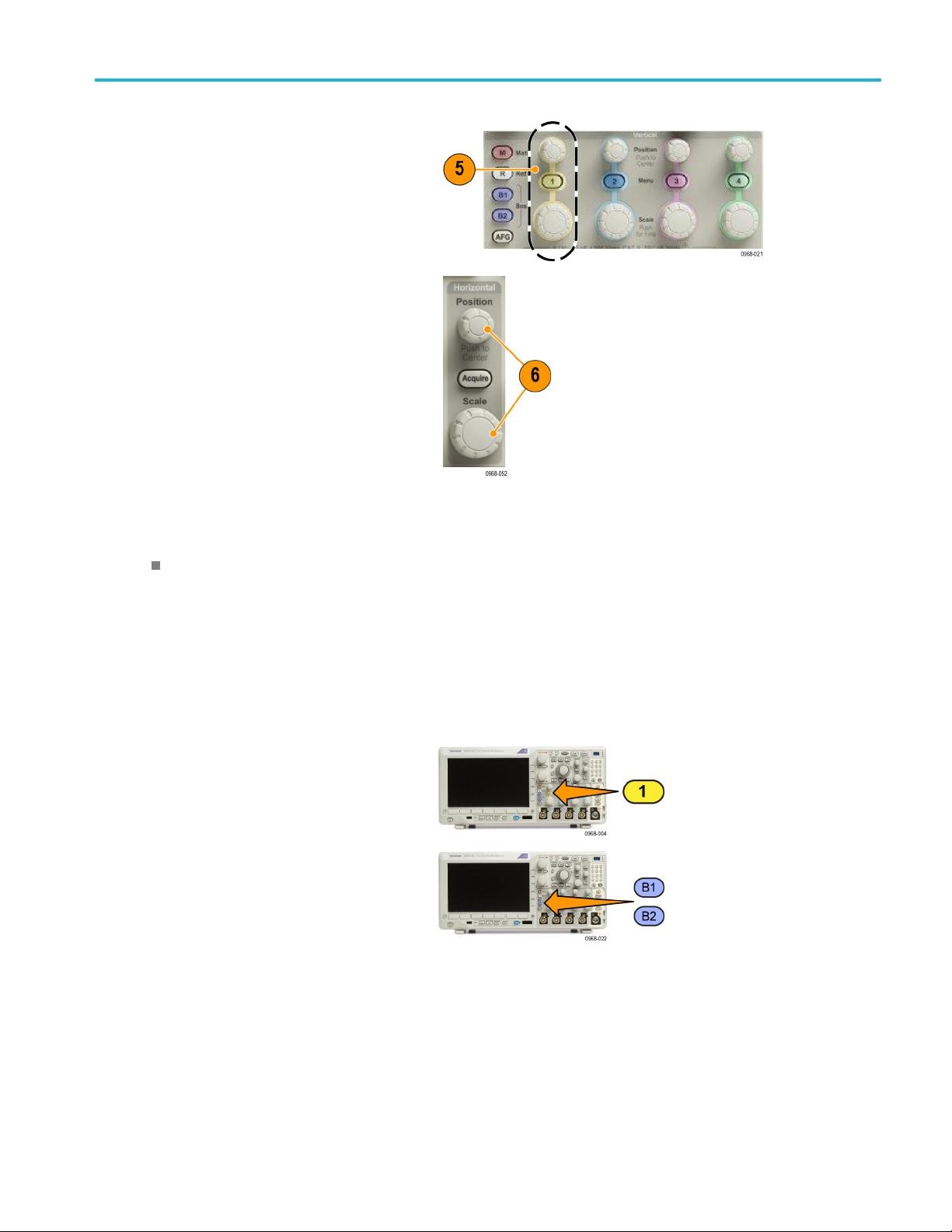
Acquire the Sign
al
5. Push the desire
adjust the vertical position and scale.
6. Adjust the horizontal position and scale.
The horizont
number of pretrigger and posttrigger
samples.
The horizon
of the acquisition window relative to the
waveform. You can scale the window to
contain a w
cycles, or thousands of cycles.
d channel button. Then
al position determines the
tal scale determines the size
aveform edge, a cycle, several
Quick Tip
Use the zoom feature to see multiple cycles of your signal in the upper part, and a single cycle in the lower part of the
display. (See page 149, Using Wave Inspector to Manage Long Record Length Waveforms.)
Labeling Channels and Buses
You can
waveform baseline indicator in the left side of the screen. The label can have up to 32 characters.
To la b
add a label to the channels and buses shown on the display for easy identification. The label is placed on the
el a channel, push a channel input button for an analog channel.
1. Push a front panel button for an input
el or a bus.
chann
MDO3000 Series Oscilloscopes User Manual 55
Page 78

Acquire the Sign
al
2. Push a lower me
nu button to create a label,
such as for channel 1 or B1.
3. Push Choose Preset Label to view a list
of labels.
4. Turn Multipurpose b to scroll through the
list to find a
suitable label. You can edit the
label after you insert it if necessary.
5. Push Inse
rt Preset Label to add the label.
If you are using a USB keyboard, use the
arrow keys to position the insertion point
t the inserted label, or type in a new
and edi
label. (See page 35, Connecting a USB
Keyboard to Your Oscilloscope.)
Label
Choose
Preset
Label
Insert
Preset
Label
6. If you do not have a USB keyboard
connected, push the side and lower menu
arrow keys to position the insertion point.
56 MDO3000 Series Oscilloscopes User Manual
Page 79
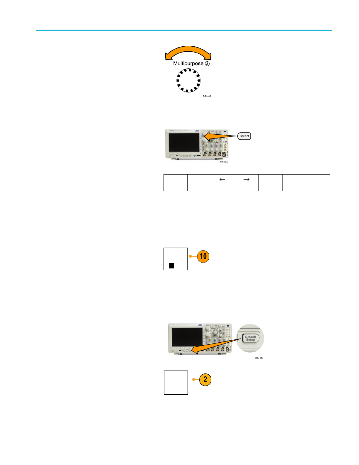
Acquire the Sign
al
7. Turn Multipurp
ose a to scroll through the
list of letters, numbers, and other characters
to find the character in the name that you
want to enter.
8. Push Select or Enter Character to let the
oscilloscope know that you have picked the
proper character to use.
You can use the lower menu buttons to edit
the label as needed.
9. Continue scrolling and pushing Select until
you have entered all the desired characters.
For another label, push the side and lower
menu arrow keys to reposition the insertion
point.
ABCDEFGHIJKLMNOPQRSTUVWXYZ
abcdefghijklmnopqrstuvwxyz
0123456789_=+-!@#$%^&*()[]{}<>/~'”\|:,.?
Enter
Character
Back
Space
Delete
Clear
10. Push Display Labels and select On to see
the label.
Using the Default Setup
To return the oscilloscope to its default settings:
1. Push Default Setup.
2. If you change your mind, push Undo
Default Setup to undo the last default
setup.
Display
Labels
On|Off
Undo
Default
Setup
MDO3000 Series Oscilloscopes User Manual 57
Page 80

Acquire the Sign
al
Using Autoset
Autoset adjusts the instrument (acquisition, horizontal, trigger, and vertical controls) such that it displays four or five waveform
cycles for analog channels with the trigger near the midlevel, and ten cycles for digital channels.
Autoset works with both the analog and digital channels.
1. To autoset an analog channel, connect the
analog probe, and then select the input
channel. (See page 54, Setting Up Analog
Channels.)
To autoset a digital channel, connect
the logic probe and select the input
channel. (See page 81, Setting Up Digital
Channels.)
2. Push Autoset to execute an Autoset.
3. If desired, push Undo Autoset to undo
the last Autoset.
You can also disable the Autoset function. To disable or enable the Autoset function:
1. Push and hold Autoset.
2. Push and hold Menu Off.
3. Release Menu Off, and then release
Autoset.
Undo
Autoset
58 MDO3000 Series Oscilloscopes User Manual
Page 81

Acquire the Sign
al
4. Select the desired setting using the side
menu.
Quick Tips
To position the waveform appropriately, Autoset may change the vertical position. Autoset always sets vertical offset
to0V.
If you use Autoset when no channels are displayed, the instrument turns on channel 1 and scales it.
If you use Autoset and the oscilloscope detects a video signal, the oscilloscope automatically sets the trigger type to
video and makes other adjustments to display a stable video signal.
Acquisition Concepts
Before a
has a dedicated input amplifier and digitizer. Each channel produces a stream of digital data from w hich the instrument
extracts waveform records.
signal can be displayed, it must pass through the input channel where it is scaled and digitized. Each channel
Autoset
Enabled
Autoset
Disabled
Sampli
Acquisition is the process of sampling an
analog signal, converting it into digital
data,
record, which is then stored in acquisition
memory.
ng Process
and assembling it into a waveform
Real-Time Sampling
MDO3000 Series oscilloscopes use
real-time sampling. In real-time sampling,
the instrument digitizes all of the points it
acquires using a single trigger event.
Input signal
Record points
Sampling rate
Sampled points
Digital values
MDO3000 Series Oscilloscopes User Manual 59
Page 82

Acquire the Sign
Waveform Record
The instrument builds the waveform record through use of the following parameters:
al
Sample interv
recorded sample points. Adjust this
by turning the Horizontal Scale knob
or pushing Ac
record length in the Acquire menu.
Record length: The number of samples
required to fill a waveform record. Set
this by push
using the lower and side menus.
Trigger point: T he zero time reference in
a waveform record. It is shown on the
screen by
Horizontal position: When Delay Mode
is on, this is the time from the trigger
point to the expansion point. Adjust this
by turning the Horizontal Position knob.
Use a positive time to acquire the record
after the trigger point. Use a negative
time to acquire it before the trigger point.
Expansion point: The point that the
horizontal scale expands and contracts
around. It is shown by an orange triangle.
al: The time between
quire and changing the
ing the Acquire button and
an orange T.
Using FastAcq
FastAcq™ provides high-speed waveform capture. It is helpful in finding elusive signal anomalies. Fast acquisition mode
es the dead time between waveform acquisitions, enabling the capture and display of transient events such as
reduc
glitches and runt pulses. Fast acquisition mode can also display waveform phenomena at an intensity that reflects their
rate of occurrence.
To use FastAcq:
1. Push Acquire.
60 MDO3000 Series Oscilloscopes User Manual
Page 83
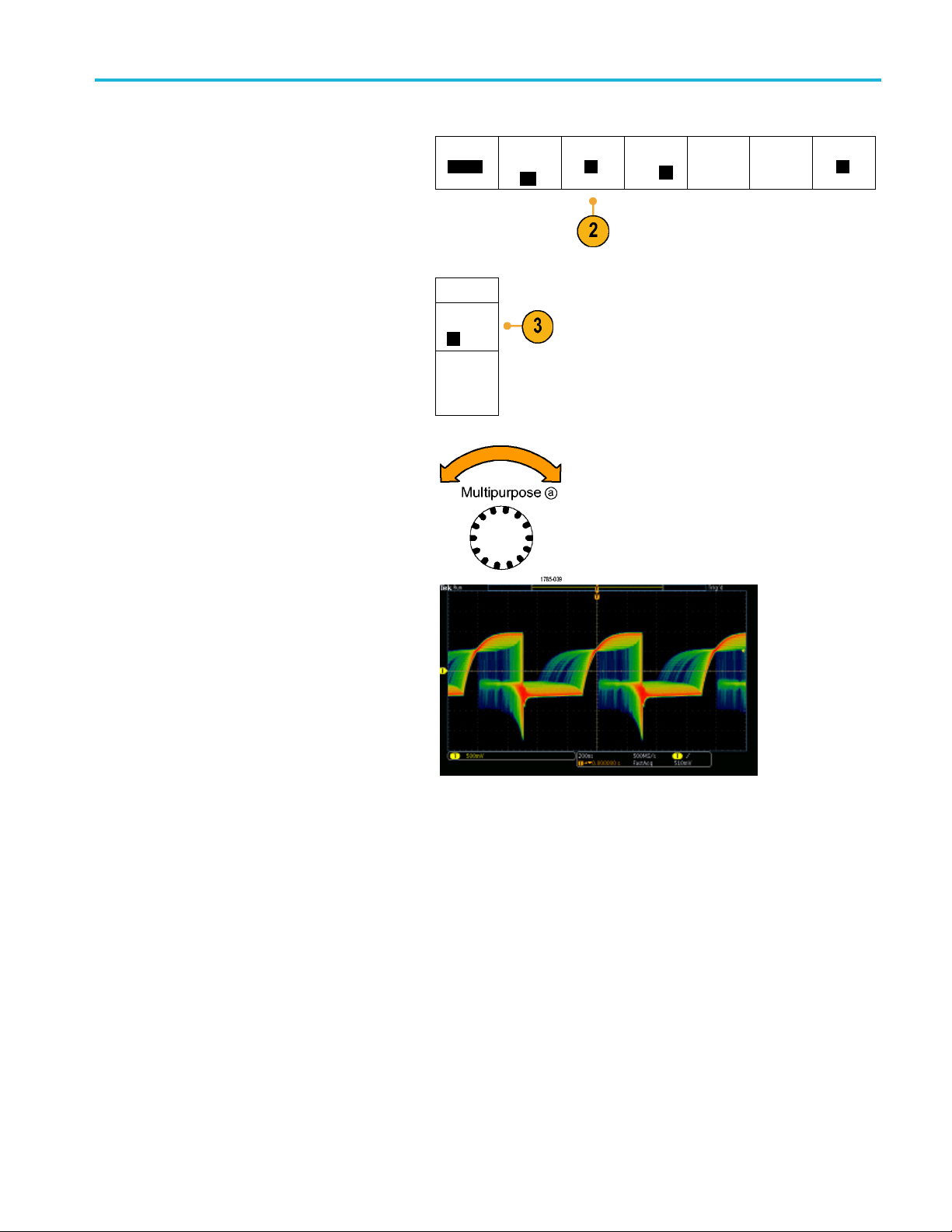
Acquire the Sign
al
2. Push FastAcq.
3. Toggle the FastAcq side-menu button to
select On.
4. Push Waveform Palette.
5. Turn the Multipurpose a knob to select the
desired display palette.
The displ
ay palette lets you enhance the visibility
of events. This choice uses intensity grading to
indicate how often rare transients occur relative
to normal
signals. The choices are Temperature,
Spectral, Normal and Inverted.
Tem pera ture uses color-grading to indicate
cy of occurrence with hot colors like
frequen
red/yellow indicating frequently occurring events
and colder colors like blue/green indicating
ccurring events.
rarely o
Spectral uses color-grading to indicate
frequency of occurrence with colder colors like
dicating frequently occurring events and
blue in
hot colors like red indicating rarely occurring
events.
l uses the default c hannel color (like
Norma
yellow for channel one) along with gray-scale
to indicate frequency of occurrence where
ently occurring events are bright.
frequ
Inverted uses the default channel color
along with gray scale to indicate frequency of
rrence where rarely occurring events are
occu
bright.
These color palettes help highlight the events
over time occur more often or, in the case of
that
infrequent anomalies, occur less often.
Mode
Sample
FastACq
Fast Acq
On Off
Waveform
Palette
aTemper-
ature
Record
Length
10k
FastAcq
Off
Delay
On
Off
Set Horiz.
Position to
10%
Waveform
Display
XY Display
Off
MDO3000 Series Oscilloscopes User Manual 61
Page 84

Acquire the Sign
al
How the Analog Acquisition Modes Work
Sample mode retains the first sampled point
from each acqu
default mode.
Peak Detect mode uses the highest and
lowest of all
consecutive acquisition intervals. This mode
only works with real-time, noninterpolated
sampling an
frequency glitches.
Hi Res mode calculates the average of all
the samples for each acquisition interval.
This mode a
noninterpolated sampling. Hi-Res provides
a higher-resolution, lower-bandwidth
waveform
isition interval. Sample is the
the samples contained in two
d is useful for catching high
lso only works with real-time,
.
Envelop
e mode finds the highest and lowest
record points over all acquisitions. Envelope
uses Peak Detect for each individual
tion.
acquisi
Average mode calculates the average value
h record point over a user-specified
for eac
number of acquisitions. Average uses
Sample mode for each individual acquisition.
Use ave
rage mode to reduce random noise.
Changing the Acquisition Mode, Record Length, and Delay Time
Use this procedure to change the acquisition mode.
1. Push Acquire.
2. Push Mode.
Mode
Sample
Record
Length
10k
FastAcq
Off
Delay
On
Off
Set Horiz.
Position to
10%
Waveform
Display
XY Display
Off
62 MDO3000 Series Oscilloscopes User Manual
Page 85

Acquire the Sign
al
3. Then choose the acquisition mode from the
side menu. You can chose from: Sample,
Peak Detect, H
NOTE. Pea
i Res, Envelope, or Average.
k Detect and Hi Res modes take advantage of sample points that the oscilloscope would have discarded at lower
Acquisition
Mode
Sample
Peak
Detect
Hi Res
Envelope
Average
16
sweep speeds. Therefore, these modes only work when the current sample rate is less than the maximum possible sample
rate. As soon as the oscilloscope starts to acquire at the maximum sample rate, then the Peak Detect, Hi Res and Sample
modes all
look the same. You can control the sample rate by setting the Horizontal scale and the Record Length.
4. If you chose Average,turnMultipurpose a
e number of waveforms to average
to set th
over.
5. Push Record Length.
6. Scroll through the available choices.
Choose among 1000, 10 k, 100 k, 1 M, 5 M,
and 10 M points.
MDO3000 Series Oscilloscopes User Manual 63
Page 86

Acquire the Sign
al
7. Push Delay on th
On when you want to delay the acquisition
relative to the trigger event.
With Delay set to On, turn the Horizontal Position knob counterclockwise to increase the delay. The trigger point will move
to the left and ultimately outside of the acquired waveform. Then you can adjust the Horizontal Scale knob to acquire more
detail around the area of interest at the center of the screen.
When this delay is on, the trigger point separates from the horizontal expansion point. T he horizontal expansion point
stays at the center of the screen. The trigger point can move off the screen. When this happens, the trigger marker turns
to point in the direction of the trigger point.
Use the delay feature when you want to acquire waveform detail that is separated from the trigger event by a significant
interval of time. For example, you can trigger on a sync pulse that occurs once every 10 ms and then look at high-speed
signal characteristics that occur 6 ms after the sync pulse.
When the delay feature is s et to Off, the expansion point is tied to the trigger point so that scale changes are centered
around the trigger point.
Using Roll Mode
e lower menu to select
Roll mode gives a display similar to a strip chart recorder for low-frequency signals. Roll mode lets you see acquired data
points w
Roll mo
ithout waiting for the acquisition of a complete waveform record.
de is enabled when the trigger mode is auto and the horizontal scale is set to 40 ms/div or slower.
Quick Tips
Switching to Envelope or Average acquisition mode, using digital channels, using math waveforms, turning on a bus,
tching to Normal trigger will disable Roll mode.
or swi
mode is disabled when you set the horizontal scale to 40 ms per division or faster.
Roll
Run/Stop to halt Roll mode.
Push
64 MDO3000 Series Oscilloscopes User Manual
Page 87

Act on Event
Tell the oscilloscope to perform a defined action after a defined event has occurred. The event can be a trigger or a certain
number of acquisitions. The action can be to:
Stop acquisitions
Save a waveform or a screen image to a file
Print
Send a pulse out the AUX OUT port
Generate a remote interface SRQ
Send an e-mail notification
Display a message on the oscilloscope display
1. Push Test.
Acquire the Sign
al
2. Push Application on the lower-menu.
3. Turn Multipurpose a to select Act on Event
4. Push Event on the lower menu.
This brings up the event type side menu.
ct the desired event type.
Sele
Application
Act on
Event
Event
Acquisition
Action Repeat
Off
MDO3000 Series Oscilloscopes User Manual 65
Page 88
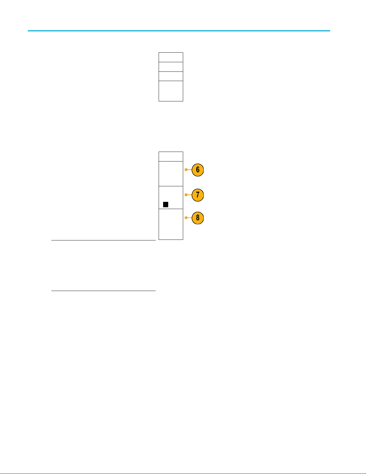
Acquire the Sign
al
Event Type
None
Trigger
Acquisi-
tions
(a) 10
5. Push Action
s on the lower menu.
This brings up the Actions side menu. Use
themenutoselectanactiontooccuronthe
event.
6. Select th
eactiontypefromtheresulting
pop-out menu.
7. Select wh
8. If you se
ether or not to enable the action.
lected E-mail Notification from the
list of actions above, you can now select
Configure E-mail from the side menu to
he parameters of the e-mail.
define t
NOTE. There is a single set of SMTP server
gs saved for both Act on Event e-mail
settin
notification and for the e-mail printer (set through
the Utility > Print Setup > Select Printer > Add
lPrintermenus). If you modify the SMTP
E-mai
settings in one of these two locations, they will
be similarly modified in the other location.
Actions
Select
Actions
(a) Stop
Acq
Enable
Action
On Off
Configure
E-mail
9. Push Repeat. from the lower menu.
This lets you set how many times to repeat
elected event and resulting action.
the s
66 MDO3000 Series Oscilloscopes User Manual
Page 89

SettingUpaSerialorParallelBus
Your oscilloscope can decode and trigger on signal events or conditions that occur on:
Bus type With this hardw are
Audio (I2S, Left Justified (LJ), Right
Justified (RJ), and TDM)
CAN, CAN FD, and LIN M DO3AUTO application module
FlexRay
I2C and SPI MDO3EMBD application module
ARINC429 and MIL-STD-1553 MDO3AERO application module
Parallel
RS-232, RS-422, RS-485, and
UART
USB 2.0 MDO3USB application module
(See page 14, Application Module Free Trial.)
MDO3AUDIO application module
MDO3FLEX application module
MDO3000 Series oscilloscope with the MDO3MSO option
MDO3COMP application module
NOTE. 1 GHz bandwidth models are required for high-speed (HS) USB.
Acquire the Sign
al
Using Buses in Two Steps
To quickly use serial bus triggering:
1. Push B1 or B2 and enter parameters of the
bus on which to trigger.
You can separately assign a different bus to
each of the B1 and B2 buttons.
MDO3000 Series Oscilloscopes User Manual 67
Page 90

Acquire the Sign
al
2. Push Trigger Me
nu and enter trigger
parameters. (See page 92, Choosing a
Trigger Type.)
You can d ispla
y bus information without
triggering on the bus signal.
SettingUpBu
s Parameters
NOTE. For most bus sources, you may use any combination of channels 1 through 4, and D15 through D0. With some
buses, you may also use Ref 1 through 4 and Math as sources for protocol decode.
To trigger
on serial or parallel bus conditions, refer to Triggering on Buses. (See page 95, Triggering on Buses.)
To set up bus parameters:
1. Push B1 or B
2 to bring up the lower bus
menu.
2. Push Bus.TurnMultipurpose a to scroll
the list of bus types and select the
through
desired bus: Parallel, ARINC429, I
2
C, SPI,
RS-232, CAN, LIN, FlexRay, Audio, USB, or
D-1553.
MIL-ST
The actual menu items shown will depend on
your model oscilloscope and the application
s installed.
module
3. Push D
efine Inputs. The choices depend
on the selected bus.
Bus B1
Parall
Define
Inputs
el
Thresholds B1 Label
Paralle
Bus
l
Display
Event
Tab l e
68 MDO3000 Series Oscilloscopes User Manual
Page 91

Acquire the Sign
al
Use the side menu buttons to define
parameters for the inputs, such as specific
signalstoana
nalog or digital channel.
If you select Parallel, push the side menu
button to ena
Push the side
ble or disable Clocked Data.
menu button to select the
Clock Edge on which to clock data: rising
edge, falling edge, or both edges.
Turn Multip
urpose a to select the Number
of Data Bits in the parallel bus.
Turn Multipurpose a to select the desired
bit to defin
e.
Turn Multipurpose b to select the desired
analog or digital channel as the source for
the bit.
4. Push Thresholds.
You can set the threshold for all channels in
the parallel or serial bus from a list of preset
. The preset values vary, depending
values
on the bus type.
Define
Inputs
Clocked
Data
No
Yes
Clock
Edge
Number of
Data Bits
(a) 16
Define Bits
(a) Bit 15
(b) D15
Bus B1
Parallel
Define
Inputs
Thresholds B1 Label
Parallel
Bus
Display
Event
Table
Alternatively, you can set the threshold to a
c value for the signals that make up the
specifi
parallel or serial bus. To do so, push Select
on the side menu and turn Multipurpose a
ect a Bit or a Channel number (Signal
to sel
name).
Then, turn Multipurpose b to define the
voltage level above which the oscilloscope
treats the signal as a logic high and below
which as a logic low.
NOTE. Some buses use two thresholds per
channel.
MDO3000 Series Oscilloscopes User Manual 69
Page 92

Acquire the Sign
al
5. Optionally, push B1 Label to edit the label for
the bus. (See page 55, Labeling Channels
and Buses.)
6. Push Bus Display and use the side menu
to define how
to display the parallel or serial
bus.
Depending on the bus, use the side menu or
the knobs t
o set the number format.
7. Push Event Table and select On to display a
us packets with timestamps.
list of b
Bus B1
Parallel
Bus
Bus and
Wave-
forms
Hex
Binary
ASCII
Event
Tabl e
On Off
Save
Event
Tabl e
Define
Inputs
Thresholds B1 Label
Parallel
Bus
Display
Event
Tab l e
For a clocked parallel bus, the table lists the value of the bus at each clock edge. For an unclocked parallel bus, the table
lists the value of the bus whenever any one of its bits changes.
ent Table lists bytes, words, or packets, depending on the bus type.
The Ev
(See page 80, Event Table .)
8. Push
Save Event Table to save the event
table data in a .csv (spreadsheet) format on
the currently selected storage device.
70 MDO3000 Series Oscilloscopes User Manual
Page 93

This example of an Event Table is from an
RS-232 bus.
RS-232 event t
ables display one line for each
7- or 8-bit byte when Packets are set to Off.
RS-232 event tables display one line for each
packet when P
ackets are set to On.
Other buses display one word, frame, or
packet per row, depending on the bus type.
9. Push B1 or B2 and turn Multipurpose a
to move the bus display up or down on the
screen.
Acquire the Sign
al
(See page 80, Event Table .)
ARINC429 Bus
To acqui
re data from an ARINC429 bus, you need to setup these items:
1. If you selected ARINC429, push Define
and the appropriate side menu
Inputs
choices.
2. Turn Multipurpose a to select the waveform
under analysis as the bus input.
3. Push either Polarity Normal or Polarity
rted to match the ARINC429 bus being
Inve
acquired
Bus B1
AR-
INC42
Define
Input
(a) 1
Polarity
mal
Nor
Polarity
Inverted
Define
Inputs
9
Thresh-
olds
800mV
0.00 V
Configu
B1 Label
re
AR-
INC42
Bus
Display
9
Event
Tab l e
MDO3000 Series Oscilloscopes User Manual 71
Page 94

Acquire the Sign
al
4. Push Thresholds to configure the high and
low thresholds for the ARINC429 bus being
acquired or se
lect from available presets.
Bus B1
AR-
INC429
Define
Inputs
5. Push Configure and select the appropriate
side menu choi
6. Push Bit Rate, and turn Multipurpose a to
select from
Alternatively, you can set the bit rate to a
specific value. To do so, select Custom, and
then turn Mu
ces.
the list of predefined bit rates.
ltipurpose b to set the bit rate
Bit Rate
100 kbps
DATA
Format
DATA
from 10 kbps to 1 Mbps
7. Push DATA f
ormat, and turn M u ltipurpose a to select from the size of the data field for packets being decoded on
the ARINC429 bus.
I2CBus
To acquire data from an I2C bus, you need to also set up these items:
1. If you select I2C, push Define Inputs and the
appropriate side menu choices.
Bus B1
I2C
Define
Inputs
Thresh-
olds
800mV
0.00 V
Thresholds Include
Configure
R/W in
Address
No
B1 Label
AR-
INC429
B1 Label
I2C
Bus
Display
Bus
Display
Event
Tabl e
Event
Table
You can assign the predefined SCLK Input
or SDA Input to the channel connected to
the signal.
2. Push Include R/W in Address and then
push the desired side button.
This control determines how the oscilloscope
2
shows the I
C addresses in bus decode
traces, cursor readouts, Event Table listings,
and trigger settings.
If you select Yes, the oscilloscope displays 7-bit addresses as eight bits, where the eighth bit (LSB) is the R/W bit. It
displays 10-bit addresses as 11 bits where the third bit is the R/W bit.
If you select No, the oscilloscope displays 7-bit addresses as seven bits, and 10-bit addresses as ten bits.
In the physical layer of the I
2
C protocol, 10 bit I2C addresses are preceded by the five bit code, 11110. The oscilloscope
does not include these five bits in address readouts.
72 MDO3000 Series Oscilloscopes User Manual
Page 95

SPI Bus
To acquire data from an SPI bus, you need to also s et up these items:
Acquire the Sign
al
1. If you selected SPI, push Defi ne Inputs and
the appropriate side menu choices.
You c an set the Framing to SS (Slave
Select) or to Idle Time.
You can assign the predefined SCLK, SS,
MOSI,orMISO signals to any channel.
2. Push Configure and the desired side menu
choices.
3. Push SCLK to set the edge of the signal to
match the SPI bus being acquired.
4. Set the level of the SS, MOSI, and MISO
signals to match the SPI bus.
Active High means that a signal is considered
active when the signal is greater than the
threshold value.
Active Low means that the signal is
considered active when the signal is lower
than the threshold value.
Bus B1
SPI
SCLK
SS
Active
High
Active Low
MOSI
Active
High
Active Low
MISO
Active
High
Active Low
-more10f2
Define
Inputs
Thresholds
Configure
B1 Label
SPI
Bus
Display
Event
Tab l e
5. Use M ultipu rp ose a to set the number of
bits of the SPI Word Size.
6. Push either side menu button to set the bit
order of the SPI bus.
Word Size
(a) 8 bits
Bit Order
MS First
Bit Order
LS First
MDO3000 Series Oscilloscopes User Manual 73
Page 96

Acquire the Sign
RS-232 Bus
To acquire data from a RS-232 bus, you need to also set up these items:
al
1. If you selected RS-232, push Configure and
the desired side menu choices.
Use the side menu to configure the bus.
Use Normal polarity for RS-232 signals and
Inverted polarity for RS-422, RS-485, and
UART buses.
2. Push Bit Rate, and turn Multipurpose a to
select the appropriate bit rate.
3. Push Data Bits and select the number to
match the bus.
4. Push Parity and turn Multipurpose a to
match the polarity used by the bus as None,
Odd, or Even.
5. Push Packets and select On or Off.
6. Turn Multipurpose a to select an
end-of-packet character.
RS-232 decoding displays a stream of bytes.
You can organize the stream into packets
with an end-of-packet character
Bus B1
RS-232
Bit Rate
9600 bps
Data Bits
7|
8
Parity
(a) None
Packets
On |
Off
End of
Packet
0A
(Linefeed)
Define
Inputs
Thresholds
Configure
9600-8-N
B1 Label
RS-232
Bus
Display
Event
Tabl e
If you defined an end-of-packet character
to use for RS-232 decoding, the stream of
bytes will be displayed as packets.
When decoding an RS-232 bus in ASCII
mode, a large dot indicates that the value
represents a character outside the printable
ASCII range.
74 MDO3000 Series Oscilloscopes User Manual
Page 97

CAN, CAN FD BUS
To acquire data from a CAN or CAN FD bus, you need to set up these items:
Acquire the Sign
al
1. If you selected CAN, push Define Inputs
and the appropriate side menu choices.
2. Turn Multipurpose a to select the channel
connected to the CAN bus source.
3. Turn Multipurpose a to select the type of
CAN signal: CAN_H, CAN_L, Rx, Tx, or
Differential.
4. Turn Multipurpose a to set the Sample
Point to a percentage of the position w ithin
the bit period or the unit interval.
For a CAN 2.0 bus the allowable s ample
point range is 5% to 95%.
For a CAN FD bus the allowable sample
point range is 15% to 95%.
NOTE. CAN FD requires an accurately specified
sample point for correct decode and triggering..
Bus B1
CAN
CAN Input
(a) 1
Signal
Type
CAN_H
Sample
Point
50%
Define
Inputs
Thresh-
olds
Configure
500 Kbps
B1 Label
CAN
Bus
Display
Event Table
NOTE. CAN FD uses the same sample point
percentage for bits transmitted at SD bit rates
and FD bit rates. For optimal performance, set
the sample point to the value used for SD bits
(the "Arbitration Phase" sample point).
5. Push Configure and select the appropriate
side menu choices..
Bus B1
CAN
Define
Inputs
Thresh-
olds
Configure
500 Kbps
4 Mbps
B1 Label
CAN
Bus
Display
Event Table
MDO3000 Series Oscilloscopes User Manual 75
Page 98

Acquire the Sign
al
6. Push Standard to select between CAN 2.0
and CAN FD decode/trigger standards.
While CAN FD is
backwards compatible
with CAN 2.0 packets, CAN 2.0 should be
selected for best performance with non CAN
FD bus configu
7. Push Bit Rat
rations.
e, and turn Multipurpose a to select from the list of predefined bit rates.
Standard
CAN 2.0
CAN FD
Bit Rate
500 kbps
FD Bit
Rate
4Mbps
FD
Standard
ISO
non-ISO
Alternatively, you can set the bit rate to a specific value. To do so, select Custom, and then turn Multipurpose b to set the
bit rate from 10 kbps to 1 Mbps.
When Stand
ard is set to CAN FD, this will be the SD bit rate.
8. If Standard is set to CAN FD, push FD Bit Rate, and turn Multipurpose a to select from the list of predefined bit rates.
ively, you can set the bit rate to a specific value. To do so, select Custom, and then turn Multipurpose b to set
Alternat
the bit rate from 500 kbps to 7 Mbps for the MDO3000.
9. If S tanda
rd is set to CAN FD, push FD Standard to select between ISO (11898-1:2015) and non-IS O (Bosch:2012)
protocol standards.
76 MDO3000 Series Oscilloscopes User Manual
Page 99

LIN Bus
To acquire data from a LIN bus, you need to also set up these items:
Acquire the Sign
al
1. If you selected LIN, push Define Inputs and
the appropriate side menu choices.
2. Turn Multipurpose a to select the channel
connected to the LIN bus source.
3. Turn Multipurpose a to set the Sample
Point from 5% to 95% of the position within
the bit period or the unit interval.
4. Select the Polarity to match the LIN bus
being acquired.
5. Push Configure and the appropriate side
menu choices.
Bus B1
LIN
LIN Input
(a) 1
Sample
Point
50%
Polarity
Normal
(High=1)
Polarity
Inverted
(High=0)
Bus B1
LIN
Define
Inputs
Define
Inputs
Thresholds
Thresholds
Configure
Configure
B1 Label
LIN
B1 Label
LIN
Bus
Display
Bus
Display
Event
Table
Event
Table
6. Push Bit Rate, and turn Multipurpose a to
select from the list of predefined bit rates.
Alternatively, you can set the bit rate to a
Bit Rate
(a)
19.2K bps
specific value. To do so, select Custom, and
then turn Multipurpose b to set the bit rate
from 800 bps to 100,000 bps.
7. Push LIN Standard, and turn Multipurpose
a to select the appropriate standard.
8. Push Include Parity Bits with Id to select
whether or not to include parity bits.
LIN
Standard
v1.x
Include
Parity Bits
with Id
On
Off
MDO3000 Series Oscilloscopes User Manual 77
Page 100

Acquire the Sign
FlexRay Bus
To acquire data from a FlexRay bus, you need to also set up these items:
al
1. If you selected FlexRay , push Define
Inputs and the desired side menu choices.
Bus B1
FlexRay
Define
Inputs
2. As appropriate, push the Threshold, Bit Rate,
Label, Bus Display and Event Table buttons
and set their corresponding parameter
values.
Audio Bus
To acquire data from an Audio bus, you need to also set up these items:
1. If you sele
cted Audio, push Define Inpu ts
and the desired side menu choices.
2. Push Typ
e, and turn Multipurpose a
to select the type of audio bus data
configuration on which to trigger.
3. Select I2S to trigger on the standard Inter-IC
Sound, or Integrated Interchip Sound,
ical serial bus interface standard stereo
electr
format.
4. Selec
t Left Justified to trigger on an I2S
stream where there is no bit clock delay and
the data starts right on the edge of the word
ct clock.
sele
5. Select Right Justified to trigger on an I2S
am where the data lines up with the right
stre
edge of the word select clock.
ect TDM to trigger on time-division
6. Sel
multiplexing.
Bus B1
Audio
Audio Bu
Type
I2S
Left
Justified
(LJ)
Right
Justified
(RJ)
TDM
Define
Inputs
s
Thresholds Bit Rate B1 Label
Thresholds
Configure
FlexRay
FlexRay
B1 Label
RS-232
Bus
Display
Bus
Display
Event
Tabl e
Event
Tabl e
sh Configure, and the appropriate
7. Pu
buttons on the side menu to further set up
I2S triggering.
78 MDO3000 Series Oscilloscopes User Manual
 Loading...