

Tektronix MDO3104, MDO3054, MDO3000 Series, MDO3014, MDO3102 Installation And Safety Instructions
...Page 1

xx
MDO3000 Series
Oscilloscopes
ZZZ
Installation and Safety
Instructions
*P071324900*
071-3249-00
Page 2

Page 3

xx
MDO3000 Series
Oscilloscopes
ZZZ
Installation and Safety
Instructions
www.tektronix.com
071-3249-00
Page 4

Copyright © Tektronix. All rights reserved. Licensed software products are owned by Tektronix or its subsidiaries
or suppliers, and are protected by national copyright laws and international treaty provisions.
Tektronix products are covered by U.S. and foreign patents, issued and pending. Information in this publication
supersedes that in all previously published material. Specifications and price change privileges reserved.
TEKTRONIX and TEK are registered trademarks of Tektronix, Inc.
Contacting Tektronix
Tektronix, Inc.
14150 SW Karl Braun Drive
P.O. Box 5 0 0
Beaverto
USA
For product information, sales, service, and technical support:
n, OR 97077
In North America, call 1-800-833-9200.
Worl dwid e, visi t www.tektronix.com to find contacts in your area.
Page 5

Table of Contents
Preface ............................................................................................................... 1
Warranties ............................... ................................ .................................. ..... 1
Accessories and Replaceable Parts .......................................................................... 1
Documentation ................................................................................................. 2
Important safety information ................. ................................ ................................ ..... 4
General safety summary ...................................................................................... 4
Service safety summary.... ................................ .................................. ................. 7
Terms in this manual ........................................... ................................ ............... 8
Symbols and terms on the product........................................................................... 8
Compliance information ........................................................................................... 9
EMC compliance ............. ................................ .................................. ............... 9
Safety compliance ............................................................................................ 10
Environmental considerations............................................................................... 13
Operating Requirements .......................................................................................... 14
Electrical Ratings ............................................................................................. 16
Input Ratings .............. ................................ .................................. .................. 17
Environmental Ratings....................................................................................... 17
Physical Specifications....................................................................................... 18
Installation Procedure ............................................................................................. 19
A Tour of Your Instrument ... .................................. ................................ .................. 20
Front-Panel Menus, Controls, and Connectors ........ ................................ .................... 20
Rear-Panel Connectors....................................................................................... 21
Power-On and Power-Off Procedure ............................................................................ 22
Functional Check ............................................................................................. 23
Compensating a TPP0250, TPP0500B or TPP1000 Passive Voltage Probe . ..... . ..... . ..... . ..... . .. 24
Application Module Free Trial .............................................................................. 26
Upgrading Firmware ....................... ................................ .................................. 27
Connecting Your Oscilloscope to a Computer... . . .... . ..... . ..... . ..... . ..... . ..... . ..... . ..... . ..... . ... 28
Getting Acquainted with the Oscilloscope.. . ..... . ..... ..... . ..... . ..... . .... . ..... . ..... . ... . . ..... . ..... . .... 31
Using the Menu System.............. ................................ ................................ ........ 31
Using the Menu Buttons ..................................................................................... 33
Using Spectral Analysis Controls........... ................................ ................................ 34
Using Other Controls......................................................................................... 35
Identifying Items in the Time Domain Display............................................................ 38
Identifying Items in the Frequency Domain Display ..................................................... 42
Identifying Items in the Arbitrary Function Generator Display ............. ............................ 43
Identifying Items in the Digital Voltmeter Display ..................... .................................. 44
まえがき .................................................................................................. 45
保証期間 ............................................................................................ 45
MDO3000 Installation and Safety Instructions i
Page 6

Table of Contents
アクセサリおよび交換可能部
品.................................................................... 45
マニュアル ........................................................................................... 47
安全性に関する重要な情報............................................................................ 48
安全にご使用いただくために ...................................................................... 48
安全に保守点検していただくために .............................................................. 51
本マニュアル内の用語 ............................................................................. 52
本製品に使用される記号と用語 ................................................................... 52
適合性に関する情報.................................................................................... 53
EMC 適合性 ......................................................................................... 53
安全性 ............................................................................................... 54
環境条件について.................................................................................. 57
動作の要件 .............................................................................................. 58
電気定格 ............................................................................................ 60
入力定格 ............................................................................................ 61
環境要件 ............................................................................................ 61
物理仕様 ............................................................................................ 62
設置手順................................................................................................. 63
ご使用機器のツアー .................................................................................... 64
前面パネルのメニュー、コントロール、コネクタ ................................................... 64
後部パネル・コネクタ ............................................................................... 65
電源投入、電源切断の手順............................................................................ 66
機能チェック......................................................................................... 67
TPP0250 型、TPP0500B 型、TPP1000 型受動電圧プローブの補正 ............................ 68
アプリケーション・モジュールの無料トライアル ................................................... 70
ファームウェアのアップグレード: .................................................................. 71
オシロスコープとコンピュータの接続 .............................................................. 72
オシロスコープの概要 .................................................................................. 75
メニュー・システムの使用........................................................................... 75
メニュー・ボタンの使用 ............................................................................. 77
スペクトラム解析コントロールの使用 .............................................................. 78
他のコントロールの使用 ............................................................................ 79
時間領域表示の項目............................................................................... 83
周波数領域表示の項目 ............................................................................ 87
任意波形ファンクション・ゼネレータ表示の項目 ................................................. 88
デジタル電圧計表示の項目 ....................................................................... 89
前言 ...................................................................................................... 91
保修 .................................................................................................. 91
附件和可更换部件 ................................................................................. 91
文档 .................................................................................................. 92
重要安全信息 ........................................................................................... 94
常规安全概要....................................................................................... 94
ii MDO3000 Installation and Safety Instructions
Page 7

Table of Contents
维修安全概要....................................................................................... 97
本手册中的术语 .................................................................................... 97
产品上的符号和术语 .............................................................................. 97
符合性信息 .............................................................................................. 98
EMC 符合性 .......................................................................................... 98
安全符合性.......................................................................................... 99
环境注意事项...................................................................................... 102
操作要求................................................................................................ 103
电源额定值......................................................................................... 105
输入额定值......................................................................................... 106
环境额定值......................................................................................... 106
物理技术规格...................................................................................... 107
安装步骤................................................................................................ 108
仪器概览................................................................................................ 109
前面板菜单、控件和连接器 ..................................................................... 109
后面板连接器...................................................................................... 110
开机和关机步骤 ....................................................................................... 111
功能检查 ........................................................................................... 112
补偿 TP
P0250、TPP0500B 或 TPP1000 无源电压探头 ........................................ 113
应用模块免费试用 ................................................................................ 115
升级固件 ........................................................................................... 115
将示波器连接到计算机........................................................................... 116
熟悉示波器 ............................................................................................. 119
使用菜单系统...................................................................................... 119
菜单按钮...................................................................................... 121
使用
使用频谱分析控件 ................................................................................ 122
使用其它控件...................................................................................... 123
识别时域显示中的项 ............................................................................. 126
识别频域画面中的项 ............................................................................. 130
识别任意波形函数发生器画面中的项 .......................................................... 131
识别数字电压表显示中的项 ..................................................................... 132
MDO3000 Installation and Safety Instructions iii
Page 8

Table of Contents
iv MDO3000 Installation and Safety Instructions
Page 9

Preface
This manual describes the installation and operation of the following
oscilloscopes:
MDO3104 MDO3054 MDO3034 MDO3024 MDO3014
MDO3102 MDO3052 MDO3032 MDO3022 MDO3012
Important safety precautions to avoid injury and prevent damage to this
product or any products connected to it
EMC (electromagnetic compliance), safety, and environmental standards with
which the product complies
Voltage, power, and environmental requirements to use the product
Installation procedure
Power-on and power-off procedure
Front- and rear-panel controls and connectors
Time, frequency, arbitrary function generator, and digital voltmeter displays
Warranties
Warranties
Warranty Description
MDO3000 oscilloscope: Three year
warranty
P6316, TPP0250, TPP0500B, and
TPP1000 probes: One year warranty
For details, refer to the w arranties in the front
of the electronic (PDF) user manual
Accessories and Replaceable Parts
Optional Accessories
Tektronix part number Description
MDO3AERO MIL-STD-1553 Serial Triggering and Analysis
MDO3AUDIO Audio Serial Triggering and Analysis (I2S, LJ, RJ, TDM)
MDO3AUTO Automotive serial triggering and analysis (CA N and LIN)
MDO3COMP Computer triggering and analysis (RS-232, RS-422, RS-485 and UART)
MDO3EMBD Embedded serial triggering and analysis (I2C and SPI)
MDO3FLEX FlexRay Serial Triggering and Analysis
MDO3USB Universal Serial Bus Triggering and Analysis (LS, FS, HS).
High speed is decode only; available on 1 GHz models only.
MDO3000 Installation and Safety Instructions 1
Page 10

Preface
Optional Accessories, (cont.)
Tektronix part number Description
MDO3LMT Limit/Mask Test
MDO3PWR
TekVPI probes that work with MDO3000 Series
oscilloscopes
TPA-BNC TekVPI to TekProbe II BNC Adapter
Power Measurement Analysis
Visit the Oscilloscope Probe and Accessory Selector Tool on the Tektronix
website at www.tektronix.com/probes
Optional Instrument Upgrades
Tektronix part number Description
MDO3AFG Arbitrary function generator
tal channels; includes P6316 digital probe
MDO3MSO
MDO3SA Increase spectrum analyzer input frequency to 3 GHz.
MDO3SEC
idth upgrades
Bandw
16 digi
ssword protected security to enable or disable all communication
Add pa
ports and firmware upgrades to any MDO3000 Series oscilloscope.
Upgrade the analog bandwidth on MDO3000 Series products post-purchase.
Visit www.tektronix.com for information on available upgrade products.
Documentation
following table lists the documentation that is available for the product and
The
shows where you can find it: in a printed manual, on the p roduct documentation
CD-ROM, or on the Tektronix Web site at www.tektronix.com.
Table 1: Product documentation
Item Purpose Location
Installation and Safety Instructions (this
manual)
User Manual Provides operation and application
Specifications and Performance
Verification Technical Reference
Provides safety and compliance
information along with hardware
installation instructions to present the
associated safety warnings. This manual
is available in English, Japanese, and
Simplified Chinese
information. This manual is available
in English, French, Italian, German,
Spanish, Japanese, Portuguese,
Simplified Chinese, Traditional Chinese,
Korean, and Russian
Specifications and procedures for
checking instrument performance.
Printed manual and also
available in electronic format at
www.tektronix.com/manuals
Product Documentation CD and available
at www.tektronix.com/manuals
Product Documentation CD and available
at www.tektronix.com/manuals
2 MDO3000 Installation and Safety Instructions
Page 11

Table 1: Product documentation, (cont.)
Item Purpose Location
Programmer Manual
Service Manual Provides information about adjustments,
Command reference for remotely
controlling the instrument.
repair, and replaceable parts.
Product Documentation CD and available
at www.tektronix.com/manuals
Available at www.tektronix.com/manuals
Preface
MDO3000 Installation and Safety Instructions 3
Page 12

Important safety information
Important saf
ety information
This manual c
for safe operation and to keep the product in a safe condition.
To safely perform service on this product, additional information is provided at
the end of this section.(See page 7, Service safety summary.)
General safety summary
Use the product only as specified. Review the following safety precautions to
avoid injury and prevent damage to this product or any products connected to it.
Carefully read all instructions. Retain these instructions for future reference.
Comply with local and national safety codes.
For correct and safe operation of the product, it is essential that you follow
generally accepted safety procedures in addition to the safety precautions specified
in this manual.
The product is designed to be used by trained personnel only.
Only qualified personnel who are aware of the hazards involved should remove
the cover for repair, maintenance, or adjustment.
ontains information and warnings that must be followed by the user
To avoid fi re or personal
injury
Before use, always check the product with a known source to be sure it is
operating correctly.
This product is not intended for detection of hazardous voltages.
Use personal protective equipment to prevent shock and arc blast injury where
hazardous live conductors are exposed.
While using this product, you may need to access other parts of a larger system.
Read the safety sections of the other component manuals for warnings and
cautions related to operating the system.
When incorporating this equipment into a system, the safety of that system is the
responsibility of the assembler of the system.
Use proper power cord. Use only the power cord specified for this product and
certified for the country of use.
Do not use the provided power cord for other products.
Ground the product. This product is grounded through the grounding conductor
of the power cord. To avoid electric shock, the grounding conductor must be
connected to earth ground. Before making connections to the input or output
terminals of the product, make sure that the product is properly grounded.
4 MDO3000 Installation and Safety Instructions
Page 13

Important safety information
Do not disable t
he power cord grounding connection.
Power disconnect. The power cord disconnects the product from the power
source. See instructions for the location. Do not position the equipment so that
it is difficult to operate the power cord; it must remain accessible to the user at
all times to allow for quick disconnection if needed.
Connect and disconnect properly. Do not connect or disconnect probes or test
leads while they are connected to a voltage source.
Use only insulated voltage probes, test leads, and adapters supplied with the
product, or indicated by Tektronix to b e suitable for the product.
Observe all terminal ratings. To avo id fire or shock hazard, observe all ratings
and markings on the product. Consult the product manual for further ratings
information before making connections to the product. Do not exceed the
Measurement Category (CAT) rating and voltage or current rating of the lowest
rated individual component of a product, probe, or accessory. Use caution when
using 1:1 test leads because the probe tip voltage is directly transmitted to the
product.
Do not apply a potential to any terminal, including the common terminal, that
exceeds the maximum rating of that terminal.
Do not float the common terminal above the rated voltage for that terminal.
Do not operate without covers. Do not operate this product with covers or panels
removed, or with the case open. Hazardous voltage exposure is possible.
Avoid exposed circuitry. Do not touch exposed connections and components
when power is present.
Do not operate with suspected failures. If you suspect that there is damage to this
product, have it inspected by qualified service personnel.
Disable the product if it is damaged. Do not use the product if it is damaged
or operates incorrectly. If in doubt about safety of the product, turn it off and
disconnect the power cord. Clearly mark the product to prevent its further
operation.
Before use, inspect voltage probes, test leads, and accessories for mechanical
damage and replace when damaged. Do not use probes or test leads if they are
damaged, if there is exposed metal, or if a wear indicator shows.
Examine the exterior of the product before you use it. Look for cracks or missing
pieces.
Use only specified replacement parts.
Use proper fuse. Use only the fuse type and rating specified for this product.
MDO3000 Installation and Safety Instructions 5
Page 14

Important safety information
Do not operate i
n wet/damp conditions. Be aware that condensation may occur if
a unit is moved from a cold to a warm environment.
Do not operate in an explosive atmosphere.
Keep product surfaces clean and dry. Remove the input signals before you c lean
the product.
Provide proper ventilation. Refer to the installation instructions in the manual for
details on installing the product so it has proper ventilation.
Slots and openings are provided for ventilation and should never be covered or
otherwise obstructed. Do not push objects into any of the openings.
Provide a safe working environment. Always place the product in a location
convenient for v iewing the display and indicators.
Avoid improper or prolonged use of keyboards, pointers, and button p ads.
Improper or prolonged keyboard or pointer use may result in serious injury.
Be sure your work area meets applicable ergonomic standards. Consult with an
ergonomics professional to avoid stress injuries.
Use only the Tektronix rackmount hardware specified for this product.
Probes and test leads
Before connecting probes or test leads, connect the power cord from the power
connector to a properly grounded power outlet.
Keep fingers behind the finger guards on the probes.
Remove all probes, test leads and accessories that are not in use.
Use only correct Measurement Category (CAT), voltage, temperature, altitude,
and amperage rated probes , test leads, and adapters for any measurement.
Beware of high voltages. Understand the voltage ratings for the probe you are
using and do not exceed those ratings. Two ratings are important to know and
understand:
The maximum measurement voltage from the probe tip to the probe reference
lead.
The maximum floating voltage from the probe reference lead to earth ground
These two voltage ratings depend on the probe and your application. Refer to the
Specifications section of the manual for more information.
WARNING. To prevent electrical shock, do not exceed the maximum measurement
or maximum floating voltage for the oscilloscope input BNC connector, probe
tip, or probe reference lead.
6 MDO3000 Installation and Safety Instructions
Page 15

Important safety information
Connect and dis
product before connecting the probe to the circuit under test. Connect the
probe reference lead to the circuit under test before connecting the probe input.
Disconnect the probe input and the probe reference lead from the circuit under test
before disconnecting the probe from the measurement product.
Connect and
connecting or disconnecting the current probe.
Connect th
Do not connect a current probe to any wire that carries voltages above the current
probe vol
Inspect the probe and accessories. Before each use, inspect probe and accessories
for damage (cuts, tears, or defects in the probe body, accessories, or cable jacket).
Do not use if damaged.
Ground
when using with ground-referenced oscilloscopes. The reference lead must be
connected to earth potential (0 V).
-referenced oscilloscope use. Do not float the reference lead of this probe
connect properly. Connect the probe output to the measurement
disconnect properly. De-energize the circuit under test before
e probe reference lead to earth ground only.
tage rating.
Servicesafetysummary
The Service safety summary section contains additional information required to
safely perform service on the product. Only qualified personnel should perform
service procedures. Read this Service safety summary and the General safety
summary before performing any service procedures.
To avoid electric shock. Do not touch exposed connections.
Do not service alone. Do not perform internal service or adjustments of this
product unless another person capable of rendering first aid and resuscitation is
present.
Disconnect power. To avoid electric shock, switch off the product power and
disconnect the power cord from the mains power before removing any covers or
panels, or opening the case for servicing.
Use care when servicing with power on. Dangerous voltages or currents may exist
in this product. Disconnect power, remove battery (if applicable), and disconnect
test leads before removing protective panels, soldering, or replacing components.
Verify safety after repair. Always recheck ground continuity and mains dielectric
strength after performing a repair.
MDO3000 Installation and Safety Instructions 7
Page 16
Important safety information
Termsinthismanual
These terms may appear in this manual:
WARNING. Warning statements identify conditions or practices that could result
in injury or loss of life.
CAUTION. Caution statements identify conditions or practices that could result in
damage to this product or other property.
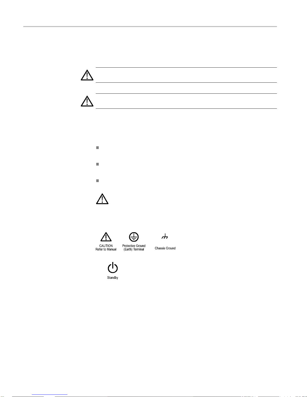
Symbols and terms on the product
These ter
The following symbol(s) may appear on the product:
ms may appear on the product:
DANGER indicates an injury hazard immediately accessible as you read
the mark
WARNING indicates an injury hazard not immediately accessible as you
read th
CAUTION indicates a hazard to property including the product.
ing.
e marking.
When this symbol is marked on the pr oduct, be sure to consult the manual
to find out the nature of the potential hazards and any actions which have to
betakentoavoidthem. (Thissymbolmayalsobeusedtorefertheuserto
ratings in the manual.)
8 MDO3000 Installation and Safety Instructions
Page 17

Compliance information
Compliance in
EMC compliance
EC Declaration of
Conformity – EMC
formation
This section
environmental standards with which the instrument complies.
Meets intent of Directive 2004/108/EC for Electromagnetic Compatibility.
Compliance was demonstrated to the following specifications as listed in the
Official Journal of the European Communiti
EN 61326-1:2006, EN 61326-2-1:2006. EMC requirements for electrical equipment
for measurement, control, and laboratory use.
CISPR 11:2003. Radiated and conducted emissions, Group 1, Class A
IEC 61000-4-2:2001. Electrostatic discharge immunity
IEC 61000-4-3:2002. RF electromagnetic field immunity
IEC 61000-4-4:2004. Electrical fast transient/burst immunity
IEC 61000-4-5:2001. Power line surge immunity
IEC 61000-4-6:2003. Conducted RF immunity
IEC 61000-4-11:2004. Voltage dips and interruptions immunity
lists the EMC (electromagnetic compliance), safety, and
es:
123
4
5
6
EN 61000-3-2:2006. AC power line harmonic emissions
EN 61000-3-3:1995. Vo ltage changes, fluctuations, and flicker
European contact.
Tektronix UK, Ltd.
Western Peninsula
West ern Ro ad
Bracknell, RG12 1RF
United Kingdom
1
This product is intended for use in nonresidential areas only. Use in residential areas may cause electromagnetic
interference.
2
Emissions which exceed the levels required by this standard may occur when this equipment is connected to a
test object.
3
For compliance with the EMC standards listed here, high quality shielded interface cables should be used.
4
Oscilloscope: ≤ 3.0 division waveform displacement and ≤ 6.0 division increase in peak-to-peak noise. RF:
Residual spurious signals in the RF section can typically increase to –50 dBm when the instrument is subjected
to electromagnetic interference per the IEC 61000-4-3 test for frequencies up to 1 GHz, and to –35 dBm for
frequencies above 1 GHz.
5
Oscilloscope: ≤ 1.0 division waveform displacement and ≤ 2.0 division increase in peak-to-peak noise. RF:
Residual spurious signals in the RF section can typically increase to –85 dBm when the instrument is subjected
to electromagnetic interference per the IEC 61000-4-6 test.
MDO3000 Installation and Safety Instructions 9
Page 18

Compliance information
Australia / New Zealand
Declaration o
Conformity – EMC
Russian Federation
Safety compliance
6
Performance Cr
levels (IEC 61000-4-11).
iterion C applied at the 70%/25 cycle Voltage-Dip and the 0%/250 cycle Voltage-Interruption test
Complies with the EMC provision of the Radiocommunications Act per the
following st
f
andard, in accordance with ACMA:
CISPR 11:2003. Radiated and C onducted Emissions, Group 1, Class A, in
accordance
with EN 61326-1:2006 and EN 61326-2-1:2006.
Australia / New Zealand contact.
Baker & McKenzie
Level 27, AMP Centre
50 Bridge Street
Sydney NSW 2000, Australia
This product is approved by the Russian government to carry the GOST mark.
This section lists the safety standards with which the product complies and other
safety compliance information.
EU declaration of
conformity – low voltage
U.S. nationally recognized
testing laboratory listing
Compliance was demonstrated to the following specification as listed in the
Official Journal o f the European Union:
Low Voltage Directive 2006/95/EC.
EN 61010-1. Safety Requirements for Electrical Equipment for Measurement,
Control, and Laboratory Use – Part 1: General Requirements.
EN 61010-2-030. Safety Requirements for Electrical Equipment for
Measurement, Control, and Laboratory Use – Part 2-030: Particular
requirements for testing and measuring circuits.
UL 61010-1. Safety Requirements for Electrical Equipment for Measurement,
Control, and Laboratory Use – Part 1: General Requirements.
UL 61010-2-030. Safety Requirements for Electrical Equipment for
Measurement, Control, and Laboratory Use – Part 2-030: Particular
requirements for testing and measuring circuits.
10 MDO3000 Installation and Safety Instructions
Page 19

Compliance information
Canadian certification
Additional compliances
Equipment type
Safety class
Pollution degree
descriptions
CAN/CSA-C22.2
Equipment for Measurement, Control, and Laboratory Use – Part 1: General
Requirements.
CAN/CSA-C22.2 No. 61010-2-030. Safety Requirements for Electrical
Equipment for Measurement, Control, and Laboratory Use – Part 2-030:
Particular requirements for testing and measuring circuits.
IEC 61010-1. Safety Requirements for Electrical Equipment for
Measurement, Control, and Laboratory Use – Part 1: General Requirements.
IEC 61010-2-030. Safety Requirements for Electrical Equipment for
Measurement, Control, and Laboratory Use – Part 2-030: Particular
requirements for testing and measuring circuits.
Test and measuring equipment.
Class1–groundedproduct.
A measure of the contaminants that could occur in the environment around
and within a product. Typically the internal environment inside a product is
considered to be the same as the external. Products should be used only in the
environment for which they are rated.
No. 61010-1. Safety Requirements for Electrical
ollution degree rating
P
IP rating
Pollution degree 1. No pollution or only dry, nonconductive pollution occurs.
Products in this category are generally encapsulated, hermetically sealed, or
located in clean rooms.
Pollution degree 2. Normally only dry, nonconductive pollution occurs.
Occasionally a temporary conductivity that is caused by condensation must
be expected. This location is a typical office/home environment. Temporary
condensation occurs only when the product is out of service.
Pollution degree 3. Conductive pollution, or dry, nonconductive pollution
that becomes conductive due to condensation. These are sheltered locations
where neither temperature nor humidity is controlled. The area is p rotected
from direct sunshine, rain, or direct wind.
Pollution degree 4. Pollution that generates persistent conductivity through
conductive dust, rain, or snow. Typical outdoor locations.
Pollution degree 2 (as defined in IEC 61010-1). Rated for indoor, dry location
use only.
IP20 (as defined in IEC 60529).
MDO3000 Installation and Safety Instructions 11
Page 20

Compliance information
Measurement and
overvoltage category
descriptions
Mains overvoltage
category rating
Measurement te
from one or more of the following categories (see specific ratings marked on
the product and in the manual).
Category II. Circuits directly connected to the building wiring at utilization
points (socket outlets and similar points).
Category III. In the building wiring and distribution system.
Category IV
NOTE. Only mains power supply circuits have an overvoltage category rating.
Only measurement circuits have a measurement category rating. Other circuits
within the product do not have either rating.
Overvoltage category II (as defined in IEC 61010-1).
rminals on this product may be rated for measuring mains voltages
. At the source of the electrical supply to the building.
12 MDO3000 Installation and Safety Instructions
Page 21

Environmental considerations
This section provides information about the environmental impact of the product.
Compliance information
Product end-of-life
handling
Restriction of hazardous
tances
subs
Observe the f
ollowing guidelines when recycling an instrument or component:
Equipment recycling. Production of this equipment required the extraction and
use of natural resources. The equipment may contain substances that could be
harmful to the environment or human health if improperly handled at the p roduct’s
end of life. To avoid release of such substances into the environment and to
reduce the
use of natural resources, we encourage you to recycle this product in
an appropriate system that will ensure that most of the materials are reused or
recycled appropriately.
This symbol indicates that this product complies with the applicable European
Union re
on waste electrical and electronic equipment (WEEE) and batteries. For
information about recycling options, check the Support/Service section of the
Tekt r on
quirements according to Directives 2002/96/EC and 2006/66/EC
ixWebsite(www.tektronix.com).
Perchlorate materials. This product contains one or more type CR lithium
batteries. According to the state of C alifornia, CR lithium batteries are
ified as perchlorate materials and require special handling. See
class
www.dtsc.ca.gov/hazardouswaste/perchlorate for additional information.
This product is classified as an industrial monitoring and control instrument,
s not required to comply with the substance restrictions of the recast RoHS
and i
Directive 2011/65/EU until July 22, 2017.
MDO3000 Installation and Safety Instructions 13
Page 22
Operating Requirements
Operating Req
MDO3000 Series
Oscilloscopes
uirements
This section
product safely and correctly. Refer to the complete product specifications in the
MDO3000 Technical Reference for additional information.
The MDO3000 oscilloscope is intended for traditional analog signal measurement
and analysis, and also for solving problems requiring use of its built-in arbitrary
function generator, mixed signal (digital and analog), and spectrum analyzer
capabilities.
Mains input frequency:
100 V to 240 V, 50/60 Hz.
115 V, 400 Hz, ±10%
Mains input voltage range: 100 V to 240 V
Maximum power input (worst case): 120 watts maximum
Maximum measurement input voltage:
Analo
, Installation Category II"
V
RMS
provides the specifications that you need to know to operate your
g inputs: 1 MΩ The maximum input voltage: At front-panel connector, 300
og inputs: 50 Ω and 75 Ω. The maximum input voltage: 5 V
Anal
at ±20 V. Not for connection to Installation Category II, III, or IV circuits.
ital inputs: The maximum input voltage at the input for the digital probe is
Dig
+30 V to -20 V peak.
Input: The maximum operating voltage: ±40 V
RF
WARNING. To reduce risk of fire and shock, ensure the mains supply voltage
fluctuations do not exceed 10% of the operating voltage range.
CAUTION. To ensure proper cooling, keep the sides and rear of the instrument
clear of obstructions. Ventilation clearance should be at least 51 mm (2 in) on
the left side, when looking at the front of the instrument, and on the rear of the
instrument.
+20 dBm (100 mW) max.
DC
with a peak
RMS
14 MDO3000 Installation and Safety Instructions
Page 23

Figure 1: MDO3000 series
Operating Requirements
TPP0250, TPP0500B, or
TPP1000 Passive Probe
Option MDO3MSO: Adds
16 digital channels and a
P6316 Digital Probe
Maximum input voltage: 300 V
CAT II safety requirements
RMS
Temperature:
Operating: –15°Cto+65°C(+5°Fto+149°F)
Nonoperating: –62 °C to +85 °C ( –80 °F to +185 °F)
Humidity: 5 % to 95% RH
Operating: 5% to 95% relative humidity (%RH) up to +30 °C, 5% to 75% RH
above +30 C up to +65 °C. Noncondensing
Nonoperating: 5% to 45% RH above +65° C up to +85 °C. Noncondensing
Altitude:
Operating: 3,000 m (9,842 ft.) maximum
Nonoperating: 12,200 m (40,000 ft.) maximum
Number of input channels: 16 digital inputs
Threshold Accuracy: ±(100 mV + 3% of threshold)
Threshold Range: –15 V to +25 V
Maximum nondestructive input signal to probe: –20 V to +30 V peak
Minimum signal swing: 500 mV
peak-to-peak
Input resistance: 101 kΩ
Input capacitance: 8.0 pF
Temperature:
Operating: 0 °C to +50 °C (+32 °F to +122 °F)
MDO3000 Installation and Safety Instructions 15
Page 24

Operating Requirements
Spectrum analyzer
Nonoperating:
Altitude:
Operating: 3,
Nonoperating: 12,000 m (39,370 ft) maximum
Pollution D
Humidity:
5% to 90% up to 40 °C relative humidity
Center frequency range:
9k Hz to 3.0 GHz (with MDO3SA installed)
9k Hz to 1.0 GHz (MDO310X, standard)
9k Hz to 500 MHz (MDO305X, standard)
9k Hz to 350 MHz (MDO303X, standard)
9k Hz to 200 MHz (MDO302X, standard)
9k Hz to 100 MHz (MDO301X, standard)
-20 °C to +60 °C (-4 °F to +140 °F)
000 m (9,843 ft) maximum
egree: 2, Indoor use only
Option MDO3AFG:
Adds a
rbitrary function
generator capability
Electrical Ratings
Power Requirements
Function types: Arbitrary, Sine, Square, Pulse, Ramp, Triangle, DC Level,
sian, Lorentz, Exponential Rise/Fall, Sin(x)/x, Random Noise, Haversine,
Gaus
Cardiac
imum frequency: 50 MHz (Sine)
Max
Maximum sample rate: 250 MS/s
Arbitrary function record length: 128K samples
Power connector
16 MDO3000 Installation and Safety Instructions
Page 25

Operating Requirements
Input
Ratings
Fuses
Batteries
The instrument
has the following power requirements:
A single-phase power source with one current-carrying conductor at or near
earth-ground
(the neutral conductor).
NOTE. Systems with both current-carrying conductors live with respect to ground
(such as phase-to-phase in multiphase systems) are n ot recommended as power
sources.
For mains supply frequency and voltage specifications, refer to Operating
Requireme
nts. . (Seepage14.)
Only the line conductor is fused for over-current protection. The fuse is internal
and not user replaceable. Do not attempt to replace the fuse. If you suspect the
fuse has
blown, return the instrument to an authorized service center for repair.
The instrument doe s not contain any user-replaceable batte ries.
Table 2: Maximum input voltage
Input Rating
At front-panel BNC connector. 1
MΩ
input voltage, 50 Ω and 75 Ω
Max
At the P6316 probe i nput, not at the
trument input
ins
300 V
De-r
5V
50 V
, Installation Category II; De-rate at 20 dB/decade between 4.5MHz and 45MHz,
RMS
ate 14db between 45Mhz and 450MHz. Above 450Mhz, 5VRMS..
with a Peak of +/- 20V (DF<=6.25%)
RMS
(threshold setting dependent)
p-p
Environmental Ratings
Table 3: Environmental specifications
Characteristic Description
Temperature
Humidity
Operating –10 °C to + 55 °C
Nonoperating
Operating 5% to 90% relative humidity (% RH) at up to +40 °C,
Nonoperating
–40 °C to +71 °C
5% to 60% RH above +40 °C up to +55 °C, non-condensing
5% to 90% RH (Relative Humidity) at up to +40 °C,
5% to 60% RH above +40 °C up to +55 °C
5% to 40% RH above +55 °C up to +71 °C, non-condensing
MDO3000 Installation and Safety Instructions 17
Page 26

Operating Requirements
Table 3: Environmental specifications, (cont.)
Characteristic Description
Altitude
Operating 3,000 m (9,842 ft)
Nonoperating
12,000 m (39,370 ft)
Physical Specifications
Table 4: Physical specifications
Characteristic Description
Dimensions
Weight
Height
Width
Depth
Net
Shipping 8.6 kg. (19 lbs), when packaged for domestic shipment
203.2 mm (8 inches) handle down, 254 mm (10.3 inches) handle up
416.6 mm (16.4 inches) max
147.4 mm (5.8 inches) max
4.2 kg (9.2 lbs), stand-alone instrument.
6.8 kg (15 lbs), with accessories and carry case.
Cleaning
Inspect the oscilloscope and probes as often as operating conditions require. To
an the exterior surface, perform the following steps:
cle
1. Remove loose dust on the outside of the oscilloscope and probes with a
nt-free cloth. Use care to avoid scratching the clear glass display filter.
li
2. Use a soft cloth dampened with water to clean the oscilloscope. Use an
ueous solution of 75% isopropyl alcohol for more efficient cleaning.
aq
CAUTION. Avoid getting moisture inside the unit during external cleaning. Use
only enough cleaning solution to dampen the cloth or swab.
CAUTION. To avoid damage to the surface of the oscilloscope or probes, do not
use any abrasive or chemical cleaning agents.
18 MDO3000 Installation and Safety Instructions
Page 27

Installation Procedure
Installation Procedure
Connecting Probes
The oscilloscope supports probes with the following:
1. Tektronix Versatile Probe Interface (TekVPI)
These probes support two-way communication with the oscilloscope through
on-screen menus and remotely through programmable support. The remote
control is useful in applications like ATE where you want the system to preset
probe parameters.
2. Tektronix Versatile Probe Interface (TekVPI) for Passive Probes
These probes build upon the functionality of the TekVPI interface. Each
probe is matched with its corresponding oscilloscope channel, allowing
the oscilloscope to optimize the signal input path. This provides AC
compensation across the frequency band.
3. TPA-BNC Adapter
The TPA-BNC Adapter allows you to use TEKPROBE II probe capabilities,
such as providing probe power, and passing scaling and unit information to
the oscilloscope.
4. BNC Interfaces
MDO3000 Installation and Safety Instructions 19
Page 28
A Tour of Your Instrument
Some of these us
scaling to the oscilloscope. Some only pass the signal and there is no other
communication.
5. Logic Probe Interface
The P6316 probe provides 16 channels of digital (on or off state) information.
6. The TPA-N-VPI Adapter a llows you to use TekVPI probes in the RF input.
For more information on the many probes available for use with MDO3000 series
oscilloscopes, refer to www.tektronix.com.
e TEKPROBE capabilities to pass the waveform signal and
A Tour of Your Instrument
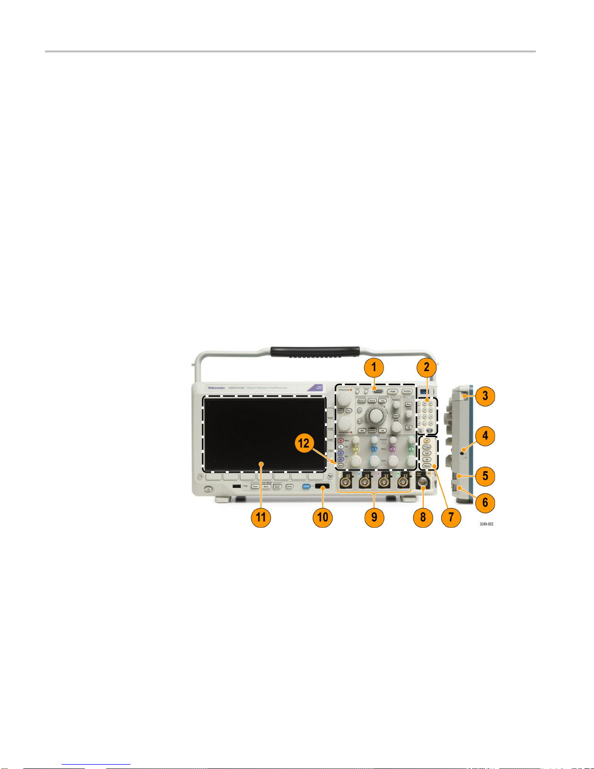
Front-Panel Menus, Controls, and Connectors
Overview
The front panel has buttons and controls for the functions that you use most often.
Use the
menu buttons to access more specialized functions.
1. Traditional oscilloscope front panel controls
2. 10-digit keypad
3. Application module slots
4. Ground strap connector
5. Ground
6. PROBE COMP
7. Dedicated spectral analysis controls
20 MDO3000 Installation and Safety Instructions
Page 29

A Tour of Your Instrument
Rear-Panel Connectors
8. Dedicated RF in
9. Analog channel (1, 2, (3, 4)) inputs with TekVPI versatile probe interface
10. Digital channel input
11. Display: shows frequency or time domain
12. Arbitrary waveform generator (AFG) enable button
put with N-connector
1. AFG OU
function generator.
2. AUX O
3. LAN. Use the LAN (Ethernet) port (RJ-45 connector) to connect the
osc
4. Video Out. Use the Video Out port (DB-15 female connector) to show the
osc
5. USB 2.0 Device port. Use the USB 2.0 High Speed Device port to connect
aP
using USBTMC protocol.
NOTE. The cable connected from the USB 2.0 Device port to the host computer
must meet the USB2.0 specification for high speed operation when connected to
a high speed host controller.
T. Use the AFG OUT port to transmit signals from the arbitrary
UT
illoscope to a 10/100 Base-T local area network.
illoscope display on an external monitor or projector.
ictBridge compatible printer, or for direct PC control of the oscilloscope
MDO3000 Installation and Safety Instructions 21
Page 30

Power-On and Power-Off Procedure
Power-On a
Power-On
6. USB 2.0 Host por
memory device or USB keyboard.
7. Power input. A
8. Lock. Use to secure the oscilloscope.
t. Use the USB 2.0 High Speed Host port to connect a USB
ttach to an AC power line with integral safety ground.
nd Power-Off Procedure
This instr
conductor at or near earth ground. The line conductor is fused for over-current
protection. A protective ground connection through the grounding conductor in
the power cord is essential for safe operation.
1. Connect the supplied power cord to the rear-panel power connector.
2. Push th
ument operates from a single-phase power source with the neutral
e power button on the instrument front-panel and the instrument will
turn on.
ower-Off
P
NOTE. The Standby button on the front-panel does not disconnect mains power.
Only the power cord at the rear of the product can disconnect mains power.
1. Push the power button on the instrument front-panel to turn the instrument off.
2. If you want to remove power completely, disconnect the power cord from the
rear-panel of the instrument.
22 MDO3000 Installation and Safety Instructions
Page 31

Functional Check
Power-On and Power-Off Procedure
Perform this quick functional check to verify that your oscilloscope is operating
correctly.
1. Connect the oscilloscope power cable as described in Powering On the
Oscilloscope. (See page 22, Power-On and Power-Off Procedure.)
2. Power on the oscilloscope.
3. Connect the proper TPP0250, TPP0500B or TPP1000 probe tip and reference
lead to the PROBE COMP connectors on the oscilloscope.
MDO3000 Installation and Safety Instructions 23
Page 32

Power-On and Power-Off Procedure
4. Push Default Setup.
5. Push Autoset. The screen should now display a square wave, approximately
5Vat1kHz.
If the signal appears but is misshapen, perform the procedures for
compensating the probe. (See page 24.)
If no signal appears, rerun the procedure. If this does not remedy the situation,
have the oscilloscope serviced by qualified service personnel.
Compensating a TPP0250, TPP0500B or TPP1000 Passive Voltage Probe
The MDO3000 Series oscilloscopes can automatically compensate TPP0250,
TPP0500B and TPP1000 probes. This eliminates the need for ma
compensation, as is typically performed with other probes.
Each compensation generates values for a specific probe and channel combination.
If you want to use the probe on another channel and desire to compensate the
new probe-channel pair, you must run a new set of compensation steps for that
new combination.
nual probe
24 MDO3000 Installation and Safety Instructions
Page 33

Power-On and Power-Off Procedure
1. Connect the osc
illoscope power cable.
2. Power on the oscilloscope.
3. Connect the probe connector to the oscilloscope channel, and the probe tip
and reference lead to the PROBE COMP terminals on the oscilloscope
front panel
.
NOTE. Connect only one probe at a time to the probe comp terminals.
4. Push a front panel button for an input channel connected to the probe you
wish to compensate. (1, 2, 3,or4)
5. Notice on the lower menu that the oscilloscope h as automatically set the
probe termination value.
6. Push More repeatedly to select Probe Setup from the resulting pop-up menu.
7. Not
ice that the compensation status starts as Default.
8. Push Compensate probe and follow t he instructions that appear on the
splay.
di
MDO3000 Installation and Safety Instructions 25
Page 34

Power-On and Power-Off Procedure
When compensat
MDO3000 Series oscilloscopes:
Each channel c
try to compensate an 11th probe on a channel, the oscilloscope will delete the
values for the least recently used probe and add the values for the new probe.
The oscilloscope will assign default compensation values to a TPP0250,
TPP0500B or TPP1000 probe connected to the Aux In channel.
NOTE. A factory calibration will delete all stored compensation values
NOTE. A probe compensation failure is most likely due to intermittent connection
of the probe tip or ground connection during the probe compensation operation.
If a failure occurs, the oscilloscope will re-use the old probe compensation values,
if they existed prior to the failed probe compensation operation.
Application Module Free Trial
A 30-day free trial is available for all application modules not installed in your
oscilloscope. The trial period begins when you power on the oscilloscope for
the first time.
ing TPP0250, TPP0500B, and TPP1000 probes on the
an store compensation values for 10 individual probes. If you
After 30 days, you must purchase the module if you want to continue using the
application. To see the date when your free trial period expires:
push the front panel Utility button,
push the lower-bezel Utility Page button,
e multipurpose knob a to select Config,
us
push the lower-bezel About button,
push the Application Modules side menu.
26 MDO3000 Installation and Safety Instructions
Page 35

Upgrading Firmware
Power-On and Power-Off Procedure
To upgrade the firmware of the oscilloscope:
1. Open a Web browser and go to www.tektronix.com/software. Proceed to the
software finder. Download the latest firmware for your oscilloscope to your
PC.
Unzip the files and copy the firmware.img file into the root folder of a USB
flash drive.
2. Power off your oscilloscope.
3. Insert the USB flash drive into the front-panel USB port on your oscilloscope.
4. Power on the oscilloscope. The oscilloscop
installs the replacement firmware.
If the oscilloscope does not install the firmware, rerun the procedure. If
the problem continues, try a different model of USB flash drive. Finally, if
needed, contact qualified service personnel.
NOTE. Do not power off the oscilloscope or remove the USB flash drive until the
scope finishes installing the firmware.
oscillo
5. Power off the oscilloscope and remove the USB flash drive.
6. Power on the oscilloscope.
7. Push Utility.
8. Push Utility Page.
9. Turn multipurpose knob a and select Config.
10. Push About. The oscilloscope displays the firmware version number.
e automatically recognizes and
11. Confirm that the version number matches that of the new firmware.
NOTE. For more information on updating the firmware, refer to the electronic
(PDF) MDO3000 User Manual.
MDO3000 Installation and Safety Instructions 27
Page 36

Power-On and Power-Off Procedure
Connecting Yo
Using VISA
ur Oscilloscope to a Computer
Connect your oscilloscope directly to a computer to let the PC analyze your data,
collect screen images, or to control your o scilloscope.
Three ways to connect your oscilloscope to a computer are through the VISA
drivers, the e*Scope® Web-enabled tools, and a socket server. Use VISA to
communicat
application, such as Tektronix OpenChoice Desktop®. Use e*Scope to
communicate with your oscilloscope through a Web browser, such as Google
Chrome or Microsoft Internet Explorer. For best results, use a browser that
supports html 5.
NOTE. For more information on connecting your oscilloscope to a computer,
includi
the electronic (PDF) MDO3000 User Manual.
VISA lets you use your MS-Windows computer to acquire data from your
loscope for use in an analysis package that runs on your PC, such as Microsoft
oscil
Excel, National Instruments LabVIEW, Tektronix OpenChoice Desktop software,
or a program of your own creation. You can use a common communications
connection, such as USB, Ethernet, or GPIB, to connect the computer to the
oscilloscope.
e with your oscilloscope from your computer through a software
ng instructions on how to save screen images and waveform data, refer to
Using e*Scope
For VISA, load the VISA drivers on your computer. Also, load your application,
such as OpenChoice Desktop. You will find the drivers and OpenChoice D esktop
software on the appropriate C D that comes with your oscilloscope or at the
ktronix software finder Web page (www.tektronix.com).
Te
With e*Scope, you can access and control any Internet-connected MDO3000
Series oscilloscope from a web browser on your computer.
Connect the oscilloscope to your network using the LAN port. The built-in
LXI web interface (Core 2011, Version 1.4) provides network configuration
information, which you can edit and customize. It also provides remote instrument
control through the e*Scope user interface. There you can control instrument
settings, save screen images, save instrument d ata or setups, and much more. Do
all this through a password-protectable web-interface.
28 MDO3000 Installation and Safety Instructions
Page 37

Power-On and Power-Off Procedure
Setting up t he oscilloscope
for connectivity
1. Connect the osc
illoscope to your computer with the appropriate USB or
Ethernet cable.
To communicate between the oscilloscope and a GPIB system, connect the
oscilloscope to the TEK-USB-488 GPIB-to-USB Adapter with a U SB cable.
Then connect the adapter to your GPIB system with a GPIB cable. Cycle the
power on the oscilloscope.
2. Push Utility.
3. Push Utility Page.
rn multipurpose knob a and select I/O.
4. Tu
5. Follow the menu items as required. For more detailed information, refer to
he MDO3000 User Manual.
t
MDO3000 Installation and Safety Instructions 29
Page 38

Power-On and Power-Off Procedure
Quick Tips
Your oscillosc
ope shipped with a CD that contains a variety of Windows-based
software tools for efficient connectivity between your oscilloscope and your
computer. These include toolbars that speed connectivity with Microsoft
Excel and Word. There is also a standalone acquisition program called
Tektronix OpenChoice Desktop.
The rear-panel USB 2.0 device port is the correct USB port for computer
connectivity. Use the rear and front panel USB 2.0 host ports to connect your
oscilloscope to USB fl ash drives. Use the USB Device port to connect your
oscillosc
USB Host p
USB Devic
ope to a PC or a PictBridge printer.
ort
eport
30 MDO3000 Installation and Safety Instructions
Page 39

Getting Acquainted with the Oscilloscope
Getting Acqua
inted with the Oscilloscope
Using the Menu System
The front pan
Use the menu buttons to access more specialized functions.
To use the menu system:
1. Push a fron
el has buttons and controls for the functions that you use most often.
t-panel menu button to display the menu that you want to use.
MDO3000 Installation and Safety Instructions 31
Page 40

Getting Acquainted with the Oscilloscope
2. Push a lower but
ton to select a menu item. If a pop-out menu appears, turn
multipurpose knob a to select the desired choice. If a pop-up menu appears,
push the button again to select the desired choice.
3. Push a side button to choose a side menu item.
If the menu item contains more than one choice, push the side button
repeatedly to cycle through the choices.
If a pop-out menu appears, turn multipurpose knob a to select the desired
choice.
32 MDO3000 Installation and Safety Instructions
Page 41

Using the Menu Buttons
Use the menu buttons to perform many functions in the oscilloscope.
Getting Acquainted with the Oscilloscope
1. Measure. Push to perform automated measurements on waveforms.
2. Search. Push to search through an acquisition for user-defined events/criteria.
3. Autoset. Push to perform an automatic setup of oscilloscope settings.
4. Test. Push to activate advanced or application-specific testing features.
5. Acquire. Push to set the acquisition mode and adjust the record length.
6. Trig
7. M. Push to manage the math waveform, including the display or removal of
8. R. Push to manage reference waveforms, including the display or removal of
9. B1 or B2.Pushtodefine and display a serial bus if you have the appropriate
10. AFG. Push to enable the arbitrary function generator.
ger Menu. Push to specify trigger settings.
math waveform from the display.
the
ch reference waveform from the display.
ea
plication modules.
ap
Parallel bus support is available on MDO3000 products.
Also, push the B1 or B2 button to display or remove the corresponding bus
from the display.
MDO3000 Installation and Safety Instructions 33
Page 42

Getting Acquainted with the Oscilloscope
11. Vertical Posit
waveform. Push to center the waveform baseline indicator.
12. Channel 1, 2, 3
waveforms and to display or remove the corresponding waveform from the
display.
13. Vertical Scale. Turn to a djust the vertical scale factor of the corresponding
waveform (volts/division). Push Fine to make smaller adjustments.
Using Spectral Analysis Controls
These buttons configure the acquisition and display of the RF input.
ion. Turn to adjust the vertical position of the corresponding
,or4Menu. Push to set vertical parameters for input
1. RF. Push to bring up the frequency domain display and menu.
2. Freq
3. Ampl
4. BW.Pushtodefine the resolution bandwidth.
5. Markers. Push to set automatic or manual markers
/Span. Push to specify the portion of the spectrum to view on the display.
Set the center frequency and the span – or set the start and stop frequency.
. Push to set the reference level.
34 MDO3000 Installation and Safety Instructions
Page 43

Getting Acquainted with the Oscilloscope
Using Other Co
ntrols
These buttons and knobs control waveforms, cursors, and other data input.
1. Cursors. Push once to activate the two vertical cursors. Push again to turn off
all cursors. Push and hold to bring up the cursor menu. Use the menu to select
the cursor features, such as type, source, orientation, linked status, and units.
When the cursors are on, you can turn the multipurpose knobs to control
their position.
2. Turn the upper multipurpose knob a, when activated, to move a cursor, to set a
numerical parameter value for a menu item, or to select from a pop-out list of
choices. Push the Fine button to toggle between coarse and fine adjustment.
Screen icons tell you when a or b are active.
3. Select. Push to activate special functions.
For example, when using the two vertical cursors (and no horizontal ones are
visible), you can push this button to link or unlink the cursors. When the two
vertical and two horizontal cursors are both visible, you can push this button
to make either the vertical cursors or the horizontal cursors a ctive.
4. Fine. Push to toggle between making coarse and fine adjustments with the
many operations of multipurpose knobs a and b
5. Turn the lower multipurpose knob b, when activated, to move a cursor or set a
numerical parameter value for a menu item. Push Fine to make adjustments
more slowly.
6. Intensity. Push to enable multipurpose knob a to control waveform display
intensity and knob b to control graticule intensity.
MDO3000 Installation and Safety Instructions 35
Page 44

Getting Acquainted with the Oscilloscope
7. Zoom button. Push to activate zoom mode.
8. Pan (outer
knob). Turn to scroll the zoom window through the acquired
waveform.
9. Zoom-sca
le (inner knob). Turn to control the zoom factor. Turning it
clockwise zooms in further. Turning it counterclockwise zooms out.
10. Play-pa
use button. Push to start or stop the automatic panning of a waveform.
Control the speed and direction with the pan knob.
11. ← Prev.
Push to jump to the previous waveform mark.
12. Set/Clear Mark. Push to establish or delete a waveform mark.
13. → Next. Push to jump to the next waveform mark.
14. Horizontal Position. Turn to adjust the trigger point location relative to
15. Horizontal Scale. Turn to adjust the horizontal scale (time/division).
36 MDO3000 Installation and Safety Instructions
theacquiredwaveforms. Pushtocenterwhendelayison. Pushtosetto
10% when delay is off.
Page 45

Getting Acquainted with the Oscilloscope
16. Autoset. Push to automatically set the vertical, horizontal, and trigger
controls for a usable, stable display.
17. Single. Push to make a single sequence acquisition.
18. Run/Stop. Push to start or stop acquisitions.
19. Trigger Level. Turn to adjust the trigger level.
Push Level to Set 50%. Push the Trigger level knob to set the trigger level to
the midpoint of the waveform.
20. Force Trig. Push to force an immediate trigger event.
21. Print. Push to print to the selected printer.
MDO3000 Installation and Safety Instructions 37
Page 46

Getting Acquainted with the Oscilloscope
22. Power switch. P
23. USB 2.0 Host port. Insert a USB peripheral to the oscilloscope, such as
a keyboard or a
24. Save. Push to perform an immediate save operation. The save operation uses
the current
25. Save / Recall Menu. Push to save and reca ll setups, waveforms, and screen
images to in
26. Default Setup. Push to perform an immediate restore of the oscilloscope
to the defa
27. Utility. Push to activate the system utility functions, such as selecting a
language
28. D15 - D0. Push to display or remove the digital channels from the display,
and to ac
29. Menu Off. Push to clear a displayed menu from the screen.
or setting the date/time.
cess the digital channel setup menu (with option MDO3MSO only).
ush to power on or off the oscilloscope.
flash drive.
save parameters, as defined in the Save / Recall menu.
ternal memory, or a USB flash drive.
ult settings.
Identifying Items in the Time Domain Display
The items shown in the graphic below may appear in the display. Not all of these
are visible at any given time. Some readouts move outside the graticule
items
area when menus are turned off.
1. The acquisition readout shows when an acquisition is running, stopped, or
2. The trigger position icon shows the trigger position in the acquisition.
38 MDO3000 Installation and Safety Instructions
when acquisition preview is in effect.
Page 47

Getting Acquainted with the Oscilloscope
3. The expansion point icon (an orange triangle) shows the point that the
horizontal scale expands and compresses around. To make the expansion
point the same as the trigger point, push Acquire and set the lower menu
Delay item to Off.
4. The waveform record view shows the trigger location relative to the waveform
. The line color corresponds to the selected waveform color. The
record
brackets show the part of the record currently displayed on the screen.
5. The trigger status readout shows trigger status.
6. The s
ecurity icon indicates when the I/O ports are disabled.
7. The cursor readout shows time, amplitude, and delta (Δ) values for each
sor. For FFT measurements, it shows frequency and magnitude. For serial
cur
and parallel buses, the readout shows the decoded values.
8. The trigger level icon shows the trigger level on the waveform. The icon color
orresponds to the trigger source color.
c
MDO3000 Installation and Safety Instructions 39
Page 48

Getting Acquainted with the Oscilloscope
9. The trigger readout shows the trigger source, slope, and level. The trigger
readouts for other trigger types show other parameters.
10. The top line of the record length/sampling rate readout shows the sampling
rate. You can adjust it with the Horizontal Scale knob. The bottom line
shows the record length. You can adjust it by pushing Acquire and Record
Length on the lower menu.
11. The horizontal position/scale readout shows on the top line the horizontal
scale (adjust with the Horizontal Scale knob). With Delay Mode on, the
bottom line shows the time from the T symbol to the expansion point icon
(adjust with the Horizontal Position knob). Use horizontal position to insert
added delay between when the trigger occurs and when you actually capture
thedata. Insertanegativetimetocapture more pretrigger information. With
Delay Mode off, the bottom line shows the time location of the trigger within
the acquisition, as a percentage.
12. The Timing Resolution readout shows the timing resolution of the digital
channels. Timing resolution is the time between samples. It is the reciprocal
of the digital sample rate. When the MagniVu control is on, “MagniVu”
appears in the readout.
13. Measurement readouts show the selected measurements
eight measurements to display at one time. A
. You can sel ect up to
symbol appears instead of
40 MDO3000 Installation and Safety Instructions
Page 49

Getting Acquainted with the Oscilloscope
the expected nu
merical measurement if a vertical clipping condition exists.
Part of the waveform is above or below the display. To obtain a proper
numerical measurement, turn the vertical scale and position knobs to make all
of the waveform appear in the display.
14. The auxiliary waveform readouts show the vertical and horizontal scale
factors of the math and reference waveforms.
15. The channel readout shows the channel scale factor (per division), coupling,
invert, and bandwidth status. Adjust with the Vertical Scale knob and in the
channel 1, 2, 3,or4 menus.
16. For digital channels, the baseline indicators point to the high and low levels.
The indicator colors follow the color code used on resistors. The D0 indicator
is black, the D1 indicator is brown, the D2 indicator is red, and so on.
17. The group icon indicates when digital channels are grouped.
18. The bus display shows decoded packet level information for serial buses or
19. For analog channels, the waveform baseline indicator shows the zero-volt
MDO3000 Installation and Safety Instructions 41
for parallel buses. The bus indicator shows the bus number and bus type.
level of a waveform, assuming you have not used any offset. The icon colors
correspond to the waveform colors.
Page 50

Getting Acquainted with the Oscilloscope
Identifyin
g Items in the Frequency Domain Display
Activate the frequency domain display by pressing the front panel RF button.
1. Vertical graticule labels
2. Start frequency
3. Reference level
4. Ve r
5. Center frequency
6. Span and resolution bandwidth
7. Stop frequency
8. Reference marker
42 MDO3000 Installation and Safety Instructions
tical scale
Page 51

Getting Acquainted with the Oscilloscope
Identifying I
tems in the Arbitrary Function Generator Display
1. If visible, the output is on
2. AFG label
3. Waveform type, e.g. “Sine”
4. Additive Noise icon
5. Frequ
6. Amplitude
ency
MDO3000 Installation and Safety Instructions 43
Page 52

Getting Acquainted with the Oscilloscope
Identifying I
tems in the Digital Voltmeter Display
1. Measurement type
2. Value of current measurement
3. Graphic (min, max, value, five-second rolling range)
4. Min
5. Max
6. Average
7. Frequency
44 MDO3000 Installation and Safety Instructions
Page 53

まえがき
まえがき
このマニュアルでは、次のオシロスコープの設置方法と操作方法について説
明します。
MDO3104 MDO3054 MDO3034 MDO3024 MDO3014
MDO3102 MDO3052 MDO3032 MDO3022 MDO3012
人体への損傷を避け、本製品や本製品に接続されている製品への損傷を
防止するための、安全性に関する要注意事項
本製品が適合している EMC 基準、安全基準、および環境基準
本製品を使用するための電圧、電力、および環境要件
設置手順
電源投入、電源切断の手順
前面パネルと後部パネルのコントロールおよびコネクタ
時間、周波数、任意波形ファンクション・ゼネレータ、デジタル電圧計の各
ディスプレイ
保証期間
保証期間
保証期間 説明
MDO3000 オシロスコープ:3 年間保証
P6316、TPP0250、TPP0500B、TPP1000
プローブ:1 年間保証
アクセサリおよび交換可能部品
オプショナル・アクセサリ
当社部品番号 説明
MDO3AERO
MDO3AUDIO
MDO3AUTO
MDO3COMP
MDO3EMBD
MIL-STD-1553 シリアル・トリガおよび解
オーディオ・シリアル・トリガおよび解析 (I
自動シリアル・トリガおよび解析 (CAN および LIN)
コンピュータ・トリガおよび解析 (RS-232、RS-422、RS-485、UART)
組込みシリアル・トリガおよび解析 (I
詳細については、『electronic (PDF) user
manual (エレクトロニック (PDF) ユーザー・
マニュアル)』の冒頭にある「warranties
(保証)」を参照
析
2
、LJ、RJ、TDM)
S
2
Cおよ
びSPI)
MDO3000 Installation and Safety Instructions 45
Page 54

まえがき
オプショナル・アクセサリ, (続き)
当社部品番号 説明
MDO3FLEX
MDO3USB
MDO3LMT
MDO3PWR
FlexRay シリアル・トリガおよび解析
USB トリガおよび解析 (LS、FS、HS)。
高速はデコード専用で、1 GHz モデルでのみ使用可能。
Limit/Mask テスト
電力測定解析
MDO3000 シリーズのオシロスコープと連携し
て機能する TekVPI プローブ
TPA-BNC
Tektronix Web サイト (www.tektronix.com/probes) の Oscilloscope
Probe and Accessory Selector Tool を参照
TekVPI-TekProbe II BNC アダプタ。
オプショナル機器のアップグレード
当社部品番号 説明
MDO3AFG
MDO3MSO
MDO3S
MDO3SEC
帯域幅
A
のアップグレード
任意波形ファンクション・ゼネレータ
16 デジタル・チャンネル (P6316 デジタル・プローブを含む)
スペクトラム・アナライザの入力周波数を 3 GHz に上げる。
パスワー
MDO3000 シリーズのオシロスコープに対するすべての通信ポートと
ファームウェア・アップグレードを有効または無効にする。
MDO3000 シリーズ製品を購入後にアナログ帯域幅をアップグレー
ド。可能なアップグレード製品については、www.tektronix.com にア
クセス
ドによって保護されたセキュリティを追加し、任意の
してください。
46 MDO3000 Installation and Safety Instructions
Page 55

マニュアル
まえがき
本製品のマニュアルと参照
先を、以下の表に示します。マニュアルのメディア
には、冊子、CD-ROM、Tektronix Web サイト(www.tektronix.com)の 3 種類が
あります。
表5: 製品マニュアル
項目 内容 参照先
設置と安全性に関する手順書(本マ
ニュアル)
ユーザ・マニュアル
仕様および性能検査のテクニカル・リ
ファレンス
プログラマ・マニュアル 本機器をリモート制御するためのコマ
安全性とコンプライアンスに関する情
報、ハードウェアの設置手順および
禁止事項(警告)について説明しま
す。英語版、日本語版、簡体字中国
語版の 3 種類があります。
操作方法および用途について説明し
ます。このマニュアルには、英語、フ
ランス語、イタリア語、ドイツ語、スペイ
ン語、日本語、ポルトガル語、簡体字
中国語、繁体字中国語、韓国語、ロ
シア語の版があります。
機器の仕様および性能チェック手順
について説明します。
ンド・リファレンス。
印刷マニュアル。PDF 版は
www.tektronix.com/manuals で入手
できます。
製品マニュアル CD。PDF 版は
www.tektronix.com/manuals でも入手
できます。
製品マニュアル CD。PDF 版は
www.tektronix.com/manuals でも入手
できます。
製品マニュアル CD。PDF 版は
www.tektronix.com/manuals でも入手
できます。
サービス・マニュアル
調整、修理、部品交換について説
明します。
PDF 版。www.tektronix.com/manuals
で入手できます。
MDO3000 Installation and Safety Instructions 47
Page 56

安全性に関する重要な情報
安全性に関する重要な情報
このマニュアルには、操作
保つために順守しなければならない情報および警告が記載されています。
このセクションの最後には、製品を安全に保守するために必要な追加情報が
記載されています。(51 ページ 「安全に保守点検していただくために」 参照)。
安全にご使用いただくために
製品は指定された方法でのみご使用ください。人体への損傷を避け、本製品
や本製品に接続されている製品の破損を防止するために、安全性に関する次
の注意事項をよくお読みください。すべての指示事項を注意深くお読みくださ
い。必要なときに参照できるように、説明書を安全な場所に保管しておいてく
ださい。
該当する地域および国の安全基準に従ってご使用ください。
本製品を正しく安全にご使用になるには、このマニュアルに記載された注意
事項に従うだけでなく、一般に認められている安全対策を徹底しておく必要が
あります。
本製品は訓練を受けた専門知識のあるユーザによる使用を想定しています。
製品のカバーを取り外して修理や保守、または調整を実施できるのは、あらゆ
る危険性を認識した専門的知識のある適格者のみに限定する必要があります。
を行うユーザの安全を確保し、製品を安全な状態に
火災や人体への損傷を
避けるには
使用前に、既知の情報源と十分に照らし合わせて、製品が正しく動作している
ことを常にチェックしてください。
本製品は危険電圧の検出用にはご利用になれません。
危険な通電導体が露出している部分では、感電やアーク・フラッシュによって
けがをするおそれがありますので、保護具を使用してください。
本製品をご使用の際に、より大きな他のシステムにアクセスしなければならない
場合があります。他
その製品コンポーネントのマニュアルにある安全に関するセクションをお読み
ください。
本機器をシステムの一部としてご使用になる場合には、そのシステムの構築者
が安全性に関する責任を果たさなければなりません。
適切な電源コードを使用してください: 本製品用に指定され、使用される国で
認定された電源コードのみを使用してください。
他の製品の電源コードは使用しないでください。
本製品を接地してください: 本製品は、電源コードのグランド線を使用して接
地します。感電を避けるため、グランド線をアースに接続する必要があります。
のシステムの操作に関する警告や注意事項については、
48 MDO3000 Installation and Safety Instructions
Page 57

安全性に関する重要な情報
本製品の入出力端子に接続す
る前に、本製品が正しく接地されていることを
確認してください。
電源コードのグランド接続を無効にしないでください。
電源の切断: 電源コードの取り外しによって主電源が遮断されます。スイッチ
の位置については、使用説明書を参照してください。電源コードの取り扱いが
困難な場所には設置しないでください。必要に応じてすぐに電源を遮断できる
ように、ユーザが常にアクセスできる状態にしておく必要があります。
着脱は正しく行ってください: プローブとテスト・リードが電圧源に接続されて
いる間は、それらを取り付けたり取り外したりしないでください。
電圧プローブ、テスト・リード、およびアダプタは、製品に付属した絶縁された
ものか、当社が製品に使用できると明示したもののみを使用してください。
すべての端子の定格に従ってください: 火災や感電の危険を避けるために、
本製品のすべての定格とマーキングに従ってください。本製品に電源を接続
する前に、定格の詳細について、製品マニュアルを参照してください。測定カ
テゴリ(CAT)の定格および電圧と電流の定格については、製品、プローブ、ま
たはアクセサリのうちで最も低い定格を超えないように使用してください。1:1 の
テスト・リードを使用するときは、プローブ・チップの電圧が直接製品に伝送さ
れるため注意が必要です。
コモン端子を含むいかなる端子にも、その端子の最大定格を超える電圧をか
けないでください。
コモン端子の定格電圧を超えてコモン端子をフローティングさせないでくださ
い。
カバーを外した状態で動作させないでください: カバーやパネルを外した状
態やケースを開いたまま動作させないでください。危険性の高い電圧に接触
してしまう可能性があります。
露出した回路への接触は避けてください: 電源が投入されているときに、露出
した接続部分やコンポーネントに触れないでください。
故障の疑いがあるときは使用しないでください: 本製品に故障の疑いがある
場合には、資格のあるサービス担当者に検査を依頼してください。
製品が故障している場合には、使用を停止してください。製品が故障してい
る場合や正常に動作していない場合には、製品を使用しないでください。安
全上の問題が疑われる場合には、電源を切って電源コードを取り外してくださ
い。誤って使用されることがないように、問題のある製品を区別できるようにし
ておいてください。
使用前に、電圧プローブ、テスト・リード、およびアクセサリに機械的損傷がな
いかを検査し、故障している場合には交換してください。金属部が露出してい
たり、摩耗インジケータが見えているなど、損傷が見られるプローブまたはテス
ト・リードは使用しないでください。
MDO3000 Installation and Safety Instructions 49
Page 58

安全性に関する重要な情報
使用する前に、製品の外観に
変化がないかよく注意してください。ひび割れや
欠落した部品がないことを確認してください。
指定された交換部品のみを使用するようにしてください。
適切なヒューズを使用してください: 本製品用に指定されたヒューズ・タイプお
よび定格のみを使用してください。
湿気の多いところでは動作させないでください: 機器を寒い場所から暖かい
場所に移動する際には、結露にご注意ください。
爆発性のガスがある場所では使用しないでください:
製品の表面を清潔で乾燥した状態に保ってください: 製品の清掃を開始する
前に、入力信号を取り外してください。
適切に通気してください: 適切な通気が得られるように製品を設置できるよう
に、マニュアルの設置手順を参照してください。
製品には通気用のスロットや開口部があります。その部分を覆ったり、通気が
妨げられたりすることがないようにしてください。開口部には異物を入れないで
ください。
安全な作業環境を確保してください: 製品は常にディスプレイやインジケータ
がよく見える場所に設置してください。
プローブおよびテスト・
リード
キーボー
ドやポインタ、ボタン・パッドは正しく使用し、長時間の連続使用は避
けてください。キーボードやポインタの使用方法を誤ると、身体に深刻な影響
が及ぶ可能性があります。
作業場が該当する人間工学規格を満たしていることを確認してください。ストレ
スに由来するけががないように、人間工学の専門家に助言を求めてください。
本製品には指定された当社のラック取り付け金具のみを使用してください。
プローブやテスト・リードを接続する前に、電源コードを使用して本機を適切に
接地された AC コンセントに接続してください。
感電を避けるために、指ガードの先に指を出さないように注意してください。
使用しないプローブ、テスト・リード、アクセサリはすべて取り外してください。
測定に使用するプローブ、テスト・リード、アダプタは、測定カテゴリ(CAT)、電
圧、温度、高度、アンペア数の定格が適切なもののみを使用してください。
高電圧に注意: 使用するプローブの電圧定格について理解し、その定格を
超えないようにしてください。特に次の 2 つの定格についてはよく理解してお
く必要があります。
プローブ・チップとプローブの基準リード間の最大測定電圧
プローブ基準リードとアース間の最大フローティング電圧
50 MDO3000 Installation and Safety Instructions
Page 59

安全性に関する重要な情報
上記の 2 つの電圧定格はプロ
は、プローブのマニュアルの仕様関連セクションを参照してください。
警告: 感電を防止するために、オシロスコープの入力 BNC コネクタ、プロー
ブ・チップ、またはプローブ基準リードの最大測定電圧や最大フローティング
電圧を超えないように注意してください。
着脱は正しく行ってください: プローブ出力を測定器に接続してから、プロー
ブを被測定回路に接続してください。被測定回路にプローブの基準リードを
接続してから、プローブ入力を接続してください。プローブ入力とプローブの
基準リードを被測
ださい。
着脱は正しく行ってください: 電流プローブの接続や切断は、被測定回路か
ら電力が失われた後に行ってください。
プローブの基準リードは、グランドにのみ接続してください。
電流プローブを、その定格電圧を超える電圧の電線に接続しないでください。
プローブとアクセサリを検査してください: 使用前には必ずプローブとアクセ
サリに損傷がないことを確認してください(プローブ本体、アクセサリ、ケーブル
被覆などの断線、裂け目、欠陥)。損傷がある場合には使用しないでください。
定回路から切断した後で、プローブを測定器から切断してく
ーブと用途によって異なります。詳細について
グランド基準のオシロスコープの使用: グランド基準のオシロスコープで使用
する場合、プローブの基準リードはフローティングさせないでください。基準リー
ドは接地電位(0 V)に接続しなければなりません。
安全に保守点検していただくために
「安全に保守点検していただくために」のセクションには、製品の保守点検を
安全に行うために必要な詳細な情報が記載されています。資格のあるサービ
ス担当者以外は、保守点検手順を実行しないでください。保守点検を行う前
には、この「安全に保守点検していただくために」と「安全にご使用いただくた
めに」を読んでください。
感電を避けてください: 露出した接続部には触れないでください。
保守点検は単独で行わないでください: 応急処置と救急蘇生ができる人がい
ないかぎり、本製品の内部点検や調整を行わないでください。
電源を切断してください: 保守点検の際にカバーやパネルを外したり、ケース
を開く前に、感電を避けるため、製品の電源を切り、電源コードを電源コンセン
トから抜いてください。
電源オン時の保守点検には十分注意してください: 本製品には、危険な電圧
や電流が存在している可能性があります。保護パネルの取り外し、はんだ付
MDO3000 Installation and Safety Instructions 51
Page 60

安全性に関する重要な情報
け、コンポーネントの交換を
な場合)、テスト・リードの切断を行ってください。
修理後の安全確認: 修理を行った後には、常にグランド導通と電源の絶縁耐
力を再チェックしてください。
本マニュアル内の用語
このマニュアルでは次の用語を使用します。
警告: 人体や生命に危害をおよぼすおそれのある状態や行為を示します。
注意: 本機やその他の接続機器に損害を与えるおそれのある状態や行為を
示します。
本製品に使用される記号と用語
本製品では、次の用語を使用します。
する前に、電源の切断、バッテリの取り外し(可能
危険: ただちに人体や生命に危険をおよぼす可能性があることを示しま
す。
警告: 人体や生命に危険をおよぼす可能性があることを示します。
注意: 本製品を含む周
す。
製品にこの記号が表記されているときは、マニュアルを参照して、想定
される危険性とそれらを回避するために必要な行動について確認し
てください。(マニュアルでは、この記号はユーザに定格を示すため
に使用される場合があります)。
本製品では、次の記号を使用します。
辺機器に損傷を与える可能性があることを示しま
52 MDO3000 Installation and Safety Instructions
Page 61

適合性に関する情報
適合性に関する情報
EMC 適合性
EC 適合宣言 - EMC
このセクションでは、本器
が適合している EMC 基準、安全基準、および環境
基準について説明します。
指令 2004/108/EC 電磁環境両立性に適合します。『Official Journal of the
European Communities』に記載の以下の基準に準拠します。
EN 61326-1:2006、EN 61326-2-1:2006: 測定、制御、および実験用途の電子
機器を対象とする EMC 基準
123
CISPR 11:2003:グループ 1、クラス A、放射および伝導エミッション
IEC 61000-4-2:2001:静電気放電イミュニティ
IEC 61000-4-3:2002:RF 電磁界イミュニティ
4
IEC 61000-4-4:2004:電気的ファースト・トランジット/バースト・イミュニティ
IEC 61000-4-5:2001:電力線サージ・イミュニティ
IEC 61000-4-6:2003:伝導 RF イミュニティ
IEC 61000-4-11:2004:電圧低下と停電イミュニティ
5
6
EN 61000-3-2:2006: AC 電源高調波エミッション
EN 61000-3-3:1995: 電圧の変化、変動、およびフリッカ
欧州域内連絡先:
Tektronix UK, Ltd.
Western Peninsula
Western Road
Bracknell, RG12 1RF
United Kingdom
1
本製品は住居区域以外での使用を目的としたものです。住居区域で使用すると、電磁干
渉の原因となることがあります。
2
本製品をテスト対象に接続した状態では、この規格が要求するレベルを超えるエミッショ
ンが発生する可能性があります。
3
ここに挙げた各種 EMC 規格に確実に準拠するには、高品質なシールドを持つインタフェー
ス・ケーブルが必要です。
4
オシロスコープ:3.0 div 以下の波形変位および 6.0 div 以下のピーク・ツー・ピーク・ノイズの増
加。RF:本製品が IEC 61000-4-3 テストによる周波数 1 GHz 以下の電磁妨害にさらされると、RF
セクションの残留スプリアス信号が –50 dBm(代表値)まで増加することがあります。また1 GHz
を超える周波数では、–35 dBm まで増加することがあります。
5
オシロスコープ:1.0 div 以下の波形変位および 2.0 div 以下のピーク・ツー・ピーク・ノイズの増
加。RF:本製品が IEC 61000-4-6 テストによる電磁妨害にさらされると、RF セクションの残留スプ
リアス信号が –85 dBm(代表値)まで増加することがあります。
MDO3000 Installation and Safety Instructions 53
Page 62

適合性に関する情報
オーストラリア/ニュー
ジーランド適合宣言 EMC
ロシア連邦
安全性
6
70%/25 サイクルの 電圧
能基準 C を適 用します(IEC 61000-4-11)。
低下および 0%/250 サイクル瞬断の各テスト・レベルにおいて、性
ACMA に従い、次の規格に準拠することで Radiocommunications Act の EMC
条項に適合しています。
CISPR 11:2003:グループ 1、クラス A、放射および伝導エミッション
(EN61326-1:2006 および EN61326-2-1:2006 に準拠)
オーストラリア/ニュージーランドの連絡先:
Baker & McKenzie
Level 27, AMP Centre
50 Bridge Street
Sydney NSW 2000, Australia
本機はロシア政府から GOST マークの表示許可を得ています。
このセクションでは、製品が適合している安全規格およびその他の基準につ
いて説明します。
EC 適合宣言 - 低電圧
米国の国家認定試験機
関のリスト
カナダ認証
『Official Journal of the European Union』にリストされている次の仕様に準拠し
ます。
低電圧指令 2006/95/EC
EN 61010-1:測定、制御、および実験用途の電子装置に対する安全基準
– 第 1 部:一般要件。
EN 61010-2-030:測定、制御、および研究用途の電子装置に対する安全
基準、第 2-030 部:試験および測定回路に固有の必要条件。
UL 61010-1:測定、制御、および実験用途の電子装置に対する安全基準
– 第 1 部:一般要件。
UL 61010-2-030:測定、制御、および研究用途の電子装置に対する安全
基準、第 2-030 部:試験および測定回路に固有の必要条件。
CAN/CSA-C22.2 No. 61010-1:測定、制御、および実験用途の電子装置
に対する安全基準 – 第 1 部:一般要件。
CAN/CSA-C22.2 No. 61010-2-030:測定、制御、および実験用途の電子
装置に対する安全基準 – 第 2-030 部:試験および測定回路に固有の必
要条件。
54 MDO3000 Installation and Safety Instructions
Page 63

適合性に関する情報
その他の適合性
機器の種類
感電保護クラス
汚染度について
IEC 61010-1:測定
– 第 1 部:一般要件。
IEC 61010-2-0
基準、第 2-030 部:試験および測定回路に固有の必要条件。
テスト機器および計測機器。
クラス 1 - アース付き製品。
製品内部およびその周辺で発生する可能性がある汚染度の尺度です。通常、
製品の内部環境は外部環境と同じとみなされます。製品は、その製品に指定
されている環境でのみ使用してください。
汚染度 1:汚染なし、または乾燥した非導電性の汚染のみが発生します。
このカテゴリの製品は、通常、被包性、密封性のあるものか、クリーン・ルー
ムでの使用を想定したものです。
汚染度 2:通常、乾燥した非導電性の汚染のみが発生します。ただし、結
露によって一時的な導電性が発生することもまれにあります。これは、標準
的なオフィス
時のみ発生します。
、制御、および実験用途の電子装置に対する安全基準
30:測定、制御、および研究用途の電子装置に対する安全
や家庭内の環境に相当します。一時的な結露は製品非動作
汚染度
IP 定格
汚染度 3:
結露時に導電性を帯びる汚染。これらは、温度、湿度のいずれも管理され
ていない屋内環境に相当します。日光や雨、風に対する直接の曝露から
は保護されている領域です。
汚染度 4:導電性のある塵、雨、または雪により持続的に導電性が生じて
いる汚染。これは一般的な屋外環境に相当します。
汚染度 2(IEC 61010-1 の定義による)。乾燥した屋内でのみ使用できます。
IP20 (IEC 60529 で定義)。
伝導性のある汚染、または通常は乾燥して導電性を持たないが
MDO3000 Installation and Safety Instructions 55
Page 64

適合性に関する情報
測定および過電圧カテゴ
リについて
主電源過電圧カテゴリ定
格
本製品の測定端子は、測定す
テゴリに評価されます。
カテゴリ II:固定設備の
よび類似する設備)。
カテゴリ III:屋内
カテゴリ IV:建物に電気を供給する起点部分。
注: 過電圧カテゴリ
定格に該当するのは測定回路のみです。製品内部のその他の回路にはいず
れの定格も該当しません。
過電圧カテゴリ II(IEC 61010-1 の定義による)。
配線および配電系統。
定格に該当するのは主電源回路のみです。測定カテゴリ
る電源電圧について次の 1 つまたは複数のカ
屋内配線に直接接続される回路(壁コンセントお
56 MDO3000 Installation and Safety Instructions
Page 65

環境条件について
適合性に関する情報
このセクションでは本製品が環境におよぼす影響について説明します。
使用済み製品の処理方
法
有害物質に関する規制
機器またはコンポーネントをリサイクルする際には、次のガイドラインを順守し
てください。
機器のリサイクル: 本
製品の製造には天然資源が使用されています。この製
品には、環境または人体に有害となる可能性のある物質が含まれているため、
製品を廃棄する際には適切に処理する必要があります。有害物質の放出を防
ぎ、天然資源の使用を減らすため、本製品の部材の再利用とリサイクルの徹
底にご協力ください。
このマークは、本製品が WEEE(廃棄電気・電子機器)およびバッテ
リに関する指令 2002/96/EC および 2006/66/EC に基づき、EU の
諸要件に準拠していることを示しています。リサイクル方法について
は、当社の Web サイト(www.tektronix.com)のサービス・セクションを
参照してください。
過塩素酸塩の取り扱い: 本製品には CR リチウム電池が搭載されて
います。CR リチウム電池はカリフォルニア州法により過塩素酸塩材と
して規定され、特別な取り扱いが求められています。詳細については、
www.dtsc.ca.gov/hazardouswaste/perchlorate を参照してください。
本機は産業用監視および制御装置に分類されており、2017 年 7 月 22 日ま
では、改訂 RoHS Directive 2011/65/EU の含有物質制限に準拠する義務は
ありません。
MDO3000 Installation and Safety Instructions 57
Page 66

動作の要件
動作の要件
このセクションでは、製品を安全かつ正しく使用するために把握しておくべき
仕様について説明します。詳細については、『MDO3000 Technical Reference
(MDO3000 テクニ
カル・リファレンス)』の製品仕様を参照してください。
MDO3000 オシロスコープは、従来のアナログ信号の測定と分析を行うための
ものです。また、組込
みの任意波形ファンクション・ゼネレータ、(デジタルとア
ナログの) 混合信号、スペクトラム・アナライザの各機能を使用する必要がある
問題を解決するためのものでもあります。
MDO3000 シリーズ・オシ
ロスコープ
電源入力周波数:
100 V ~ 240 V、50/60 Hz
115 V、400 Hz (±10%)
電源入力電圧範囲:100 V ~ 240 V
最大電力入力 (
ワースト・ケース):最大 120 ワット
最大測定入力電圧:
アナログ入力:1 MΩ 最大入力電圧:前面パネル・コネクタでは 300 V
RMS
、イン
ストール・カテゴリ II。
アナログ入力:50 Ω および 75 Ω。最大入力電圧:5 V
(ピーク時には ±20
RMS
V)。インストール・カテゴリ II、III、IV 回路には接続しないでください。
デジタル入力:デジタル・プローブへの入力時の最大入力電圧は、+30 V ~
-20 V ピーク。
RF 入力:最大動作電圧:±40 V
+20 dBm (100 mW) 最大。
DC
警告: 出火および感電のリスクを減らすため、主電源の電圧変動が動作電圧
レンジ
の 10% を超えていないことを確認してください。
注意: 正しく冷却するために、機器の側面と背面には障害物を置かないでく
ださい。通気のために、機器の前面から見て左側および後面に 51 mm 以上
の隙間を確保してください。
58 MDO3000 Installation and Safety Instructions
Page 67

図 2: MDO3000 シリーズ
動作の要件
TPP0250 、 TPP0500B 、
TPP1000 受動プローブ
オプション MDO3MSO:16
のデジタル・チャンネルと
1 つの P6316 デジタル・
プローブを追加
最大入力電圧:300 V
CAT II 安全基準
RMS
温度:
動作時:–15 ℃ ~ +65 ℃
非動作時:–62 ℃ ~ +85 ℃
湿度:相対湿度 5 ~ 95%
動作時:相対湿度 5% ~ 95% (+30 ℃ 以下)、相対湿度 5% ~ 75% (+30 ℃ 超、
+65 ℃ 以下)、結露なきこと
非動作時:+65 ℃ 超、+85 ℃ 以下で 5% ~ 45% の相対湿度 (RH)、結露なきこと
高度:
動作時:最高 3,000 m
非動作時:最高 12,200 m
入力チャンネル数: 16 デジタル入力
スレッショルド確度:±(100 mV + スレッショルドの 3%)
スレッショルド範囲:–15 V ~ +25 V
プローブへの最大非破壊入力信号:–20 V から +30 V ピーク
最小信号スイング:500 mV
p-p
入力抵抗:101 kΩ
入力キャパシタンス:8.0 pF
動作時:0 ℃ ~ +50 ℃
MDO3000 Installation and Safety Instructions 59
温度:
Page 68

動作の要件
スペクトラム・アナライザ
非動作時:-20 ℃~ +60
高度:
動作時:最高 3,000 m
非動作時:最高 12,000 m
汚染度:2、ただし、
湿度:
40 ℃以下で相対湿度 5% ~ 90%
中心周波数範囲:
9k Hz から 3.0 GHz (MDO3SA をインストールした場合)
9k Hz から 1.0 GHz (MDO310X、標準)
9k Hz から 500 MHz (MDO305X、標準)
9k Hz から 350 MHz (MDO303X、標準)
9k Hz から 200 MHz (MDO302X、標準)
9k Hz から
100 MHz (MDO301X、標準)
℃
屋内使用のみ
オプション MDO3AFG:任
意波形ファンクション・ゼ
ネレータ機能を追加
電気定格
電源要件
ファンクションのタイプ: 任意波形、正弦波、方形波、パルス波、ランプ波、三
角波、DC レベル、ガウシャン、ローレンツ、指数立上り/立下り、Sin(x)/x、不規
則ノイズ、
最大周波数: 50 MHz (正弦波)
最大サン
任意波形ファンクションのレコード長: 128K サンプル
電源コネクタ
ヘイバーサイン、心電図
プル・レート:250 MS/s
60 MDO3000 Installation and Safety Instructions
Page 69

動作の要件
ヒューズ
バッテリ
入力定格
本製品の電源要件は次のとお
りです。
片方の通電導体が接地またはその近傍の電位の(中性線)単相電源。
注: 両方の通電導体が接
地に対して電位を持つ方式(多相方式における相
間など)は、電源として推奨されません。
電源周波数および電圧の仕様については、「動作の要件」を参照してくだ
さい。 . (58 ページ参照)。
ライン側にのみ、過
電流保護のためにヒューズが付けられています。この内蔵
ヒューズはユーザによる交換を想定したものではありません。ヒューズの交換
はしないでください。ヒューズが飛んでいると思われる場合は、認定サービス・
センターに機器を返送して修理を受けてください。
本機器には、ユーザが交換可能なバッテリは含まれていません。
表 6: 最大入力電圧
入力 定格
前面パネル
MΩ
最大入力電圧、50 Ω および
75 Ω
P6316 プローブ入力 (機器の入
力ではな
環境要
BNC コネクタ、 1
い)
件
300 V
45Mhz から 450MHz までの範囲では 14db の低下。450Mhz を超える場合、5VRMS。
5V
50 V
表 7: 環境仕様
特性 説明
温度
動作時
非動作時
–1
–40℃~+71℃
、インストール・カテゴリ II。4.5MHz から 45MHz までは 20 dB/decade、
RMS
ピーク +/- 20V (DF<=6.25%)
RMS
(スレッショルド値設定に依存)
p-p
0℃~+55℃
MDO3000 Installation and Safety Instructions 61
Page 70

動作の要件
表 7: 環境仕様, (続き)
特性 説明
湿度
高度
動作時
非動作時
動作時
非動作時
+40 ℃以下で 5% ~ 90% の相対湿度(RH)
+40 ℃ 超、+55 ℃ 以下で 5% ~ 60% の相対湿度(RH)、結露なし。
+40 ℃ 以下で 5% ~ 90% の相対湿度(RH)
+40 ℃ 超、+55 ℃ 以下で 5% ~ 60% の相対湿度(RH)
+55 ℃ 超、+71 ℃ 以下で 5% ~ 40% の相対湿度(RH)、結露なし。
3,000 m
12,000 m
物理仕様
表 8: 物理仕様
特性 説明
寸法
重量
高さ
幅
奥行き 最大 147.4 mm
本体 4.2 kg、スタンドアローン機器の場合
ハンドルを下げた状態で 203.2 mm、ハンドルを上げた状態で 254 mm
最大 416.6 mm
6.8 kg、アクセサリおよびキャリング・ケース付き
クリーニング
輸送
8.6 kg、国内出荷梱包時
動作状
況に応じた頻度でオシロスコープとプローブを検査してください。外部
表面の汚れを落とすには、次のようにします。
1. 乾い
た柔らかい布で、オシロスコープとプローブの表面についた塵を落とし
ます。ガラスのディスプレイ・フィルタを傷つけないように注意してください。
で湿らせたやわらかい布を使用して、オシロスコープの汚れを拭き取りま
2.水
す。75% イソプロピル・アルコール水溶剤を使用すると汚れがよく落ちます。
注意: 外面をクリーニングしているときにユニット内部が湿らないようにしてく
ださい。綿棒または布は、クリーニング溶液で十分に湿らせてから使用してく
ださい。
注意: 研磨剤や化学洗浄剤は使用しないでください。機器やプローブの 表
面が損傷する可能性があります。
62 MDO3000 Installation and Safety Instructions
Page 71

設置手順
設置手順
プローブの接続
オシロスコープとプローブは次の方法で接続できます。
1. Tektronix 汎用プローブ・インタフェース(TekVPI)
これらのプローブは、画面上のメニューおよびリモート設定可能な機能を
通して、オシロスコープとの双方向通信をサポートしています。リモート・コ
ントロー
なアプリケーションで役に立ちます。
2. 受動プ
これらのプローブは TekVPI インタフェースの機能に基づいています。各プ
ローブ
プの入力パスを最適化します。 これにより、全周波数帯域に AC 補正が
適用されます。
3. TPA-BNC 型アダプタ
T
や単位情報をオシロスコープに送るような、TEKPROBE II プローブの機能
が使用可能になります。
4. BNC インタフェース
ルは、システムがプローブのパラメータをプリセットする ATE のよう
ローブ用 Tektronix 汎用プローブ・インタフェース(TekVPI)
をオシロスコープの対応するチャンネルとマッチさせ、オシロスコー
PA-BNC アダプタにより、プローブに電源を供給したりスケーリング情報
MDO3000 Installation and Safety Instructions 63
Page 72

ご使用機器のツアー
これらのインタフェースの中
スケーリング情報をオシロスコープに送るものもありますが、波形信号のみ
を送るものもあります。
5. ロジック・プローブ・インタフェース
P6316 型プローブ
提供します。
6. TPA-N-VPI ア
きます。
MDO3000 シリ
ては、www.tektronix.com を参照してください。
ーズ・オシロスコープで使用可能な各種プローブの詳細につい
は、16 チャンネルのデジタル(オン/オフ状態)情報を
ダプタを使用すると、RF 入力で TekVPI プローブを使用で
には TEKPROBE 機能を使用して波形信号と
ご使用機器のツアー
前面パネルのメニュー、コントロール、コネクタ
概要
前面パネルには、頻繁に使用する機能に対するボタンとコントロールが備えら
れています。メニュー・ボタンを使用すると、さらに高度な機能にアクセスできま
す。
1. 従来のオシロスコープ前面パネル・コントロール
2. 10 個の数字で構成されたキーパッド
3. アプリケーション・モジュール・スロット
4. グランド・ストラップ・コネクタ
5. グランド
64 MDO3000 Installation and Safety Instructions
Page 73

ご使用機器のツアー
後部パネル・コネクタ
6. PROBE COMP(プロー
7. スペクトラム解析専用コントロール
8. RF 専用入力 (N コネクタ)
9. アナログ・チャネル (1、2、(3、4)) (TekVPI 汎用プローブ・インタフェース)
10. デジタル・チャンネル入力
11. ディスプレイ:周波数領域または時間領域を表示します。
12. 任意波形ゼネレータ
ブ補正)
(AFG) を有効にするボタン
1. AFG OUT (AFG 出力)。AFG OUT ポートは、任意波形ファンクション・ゼ
ネレータからの信号を送信する場合に使用します。
2. AUX OUT (AUX 出力)
3. LAN。LAN(イーサネット)ポート(RJ-45 コネクタ)を使用して、10/100 Base-T
ローカル・エリア・ネットワークにオシロスコープを接続します。
4. Video Out (ビデオ出力)。ビデオ出力ポート(DB-15 メス型コネクタ)を使用
すると、外部モニタやプロジェクタ上にオシロスコープの画面を表示できま
す。
MDO3000 Installation and Safety Instructions 65
Page 74

電源投入、電源切断の手順
5. USB 2.0 Device p
ポートに PictBridge 対応プリンタを接続します。また、USBTMC プロトコル
を使用して、PC からオシロスコープを直接制御することもできます。
注: USB 2.0 デバイス・ポートとホスト・コンピュータを接続するケーブルは、高
速ホスト・コントローラに接続する場合の高速動作に関する USB2.0 仕様に準
拠していなければなりません。
6. USB 2.0 ホスト・ポート。USB メモリ・デバイスまたは USB キーボードに接続
する場合、USB 2.0 高速ホスト・ポートを使用します。
7. Power input (電源入力)。アース付きの AC 電源ケーブルを接続します。
8. Lock (ロック)。オシロスコープを盗難から保護するために使用します。
ort (USB 2.0 デバイス・ポート)。USB 2.0 高速デバイス・
電源投入、電源切断の手順
本製品は接地電位近傍の中性線を有する単相電源で動作します。ライン側に
は、過電流保護のためにヒューズが付けられています。安全な操作のために
は、電源コ
ード内の接地線を通じた保護用のグランド接続が不可欠です。
電源投入
1. 付属の電源コードを後部パネルの電源コネクタに接続します。
2. 前面パネルの電源ボタンを押して、電源を投入します。
注: 前面パネルのスタンバイ・ボタンは、押しても主電源を切断できません。主
電源を切断するには、後部パネルの電源コードを抜く必要があります。
66 MDO3000 Installation and Safety Instructions
Page 75

電源投入、電源切断の手順
電源の遮断
機能チェック
1. 前面パネルの電源ボタンを押
2. 電源を完全に遮断するには、後部パネルから電源コードを引き抜きます。
以下の簡単な機能チェックを実行して、オシロスコープが正常に動作している
か確認します。
して、本製品をオフにします。
1. 「オシロスコープの電源の投入」の説明に従って、オシロスコープの電源
ケーブルを接続します。 (66 ページ 「電源投入、電源切断の手順」 参照)。
2. オシロスコープの電源をオンにします。
3. 適切な TPP0250、TPP0500B、TPP1000 型プローブ・チップと基準リードを、
オシロスコープの PROBE COMP コネクタに接続します。
MDO3000 Installation and Safety Instructions 67
Page 76

電源投入、電源切断の手順
4. Default Setup(工場出荷時設定)を押します。
5. オートセットを押します。振幅約 5 V、周波数 1 kHz の方形波が画面に表
示されます。
信号は表示されているのに形状がゆがんでいる場合は、プローブの補正
手順を実行します。 (68 ページ参照)。
信号が表示されない場合は、同じ手順を再度実行します。それでも問題
が解消されない場合は、
理を依頼してください。
資格のあるサービス担当者にオシロスコープの修
TPP0250 型、TPP0500B 型、TPP1000 型受動電圧プローブの補正
MDO3000 シリーズ・オシロスコープは、TPP0250 型、TPP0500B 型、TPP1000
型プローブを自動的に補正することができます。これにより、他のプローブで
は必要な手動によるプローブの補正作業が不要となります。
補正では、特定のプローブとチャンネルの組み合わせに応じて、複数の値が
生成されます。そのプローブを他のチャンネルで使用するために、プローブと
チャンネルの新たな組み合わせで補正する場合は、その組み合わせについて
一連の新規補正ステップを実行しなければなりません。
68 MDO3000 Installation and Safety Instructions
Page 77

電源投入、電源切断の手順
1. オシロスコープの電源コード
を接続します。
2. オシロスコープの電源をオンにします。
3. プローブ・コネクタをオシロスコープのチャンネルに接続し、プローブのチッ
プと基準リードをオシロスコープの前面パネルにある PROBE COMP 端子
に接続します。
注: 同時に複数のプローブをプローブの補正端子に接続することはできませ
ん。
4. 補正するプローブに接続している入力チャンネルの前面パネル・ボタンを
押します (1、2、3、4 のいずれか)。
5. 下のメニューに、プローブの終端値が自動的に設定されていることに注意
してください。
6. More(次へ)を繰り返し押して、表示されるポップアップ・メニューからProbe
Setup(プローブ設定)を選択します。
7. 補正ステータスは、Default(デフォルト)から始まることに注意してください。
8. Compensate probe(プローブの補正)を押して、画面に表示される指示に
従います。
MDO3000 Installation and Safety Instructions 69
Page 78

電源投入、電源切断の手順
MDO3000 シリーズ・オ
型プローブの補正を行う場合は次のことに注意してください。
各チャンネルには、プロー
チャンネルで 11 本目のプローブの補正を行うと、使用された最も古いプ
ローブの値が削除され、新しいプローブの値が追加されます。
Aux In (Aux 入力) チャンネルに接続された TPP0250 型、TPP0500B 型、
TPP1000 型プローブには、デフォルトの補正値が割り当てられます。
注: 工場での校正を行うと格納された補正値はすべて消去されます。
注: プローブの補正が失敗した場合、その原因の多くは、プローブ・チップま
たはグランド接続の補正中の断続的な接続不良です。補正に失敗した場合、
プローブ補正の
されます。
失敗前に補正値が存在すれば、その補正値が引き続き使用
シロスコープで TPP0250 型、TPP0500B 型、TPP1000
ブ 10 本分の補正値が保存されます。特定の
アプリケーション・モジュールの無料トライアル
オシロスコープにインストールされていないアプリケーション・モジュールは、ど
れも 30 日間無料で試用できます。トライアル期間は、初めてオシロスコープの
電源をオンにした時点から起算されます。
30 日経過後も継続使用するには、モジュールをご購入いただく必要がありま
す。トライアル期間の終了日を確認するには、次のようにします。
前面パネルの Utility (ユーティリティ) ボタンを押します。
下のベゼルの Utility Page(ユーティリティ・ページ)ボタンを押します。
汎用ノブ a を使用して Config(設定)を選択します。
下のベゼルの About(バージョン情報)ボタンを押します。
pplication Modules (アプリケーション・モジュール) サイド・メニューを押し
A
ます。
70 MDO3000 Installation and Safety Instructions
Page 79

ファームウェアのアップグレード:
電源投入、電源切断の手順
オシロスコープのファーム
します。
1. Web ブラウザを開いて
ウェア・ファインダを実行します。ご使用のオシロスコープ用の最新ファー
ムウェアを PC にダウンロードします。
ダウンロードしたファイルを解凍し、firmware.img ファイルを USB フラッシュ・
ドライブのルート・フォルダにコピーします。
2. オシロスコープの電源を切ります。
3. USB フラッシュ・ドライブをオシロスコープの前面パネルにある USB ポート
に挿入します。
ウェアをアップグレードするには、次の手順を実行
、www.tektronix.com/software にアクセスし、ソフト
4. オシロスコープの電源をオンにします。アップグレード用ファームウェアが
自動的に認識され、インストールされます。
ファームウェアのインストールが開始されない場合は、同じ手順を再度実
行します。手順を繰り返してもインストールできない場合は、別の USB フ
ュ・ドライブを試してください。それでも問題が解決しない場合は、当
ラッシ
社営業所にご連絡ください。
注: ファームウェアのインストールが完了するまで、オシロスコープの電源を
切ったり、USB フラッシュ・ドライブを取り外したりしないでください。
5. オシロスコープの電源を切って、USB フラッシュ・ドライブを取り外します。
6. オシロスコープの電源をオンにします。
7. Utility (ユーティリティ) を押します。
8. Utility Page(ユーティリティ ページ)を押します。
9. 汎用ノブ a を回して、Config(設定)を選択します。
MDO3000 Installation and Safety Instructions 71
Page 80

電源投入、電源切断の手順
10. About(バージョン情報
ジョンが表示されます。
11. バージョン番号が、新しい
します。
注: ファームウェアの更新について詳しくは、『electronic (PDF) MDO3000 User
Manual (エレクトロニック (PDF) MDO3000 ユーザ・マニュアル)』を参照してくだ
さい。
オシロスコープとコンピュータの接続
PC でデータの解
には、オシロスコープをコンピュータに直接接続します
オシロスコープ
ライバを経由する方法、もう 1 つは Web に対応した e*Scope ツールを使用す
る方法、そして 3 つ目はソケット・サーバを使用する方法です。VISA を使用す
ると、コンピュータからソフトウェア・アプリケーション (Tektronix OpenChoice デ
スクトップ® など) を介してオシロスコープと通信できます。e*Scope を使用する
と、Web ブラウザ (Google Chrome または Microsoft Internet Explorer など) を
介してオシ
のブラウザを使用してください。
析、スクリーン・イメージの収集、オシロスコープの制御を行う
をコンピュータに接続する方法は 3 つあります。1 つは VISA ド
ロスコープと通信できます。最良の結果を得るには、HTML 5 対応
)を押します。オシロスコープにファームウェアのバー
ファームウェアの番号に一致していることを確認
VISA の使用
e*Scope の使用
注: スクリーン・イメージや波形データを保存する方法を含め、オシロスコープ
をコンピュータに接続する方法について詳しくは、『electronic (PDF) MDO3000
User Manual (エレクトロニック (PDF) MDO3000 ユーザ・マニュアル)』を参照し
てください。
ISA を使用すると、オシロスコープから Windows コンピュータへデータを取り込
V
み、そのデータを Microsoft Excel、National Instruments LabVIEW、Tektronix
OpenChoice デスクトップ・ソフトウェア、その他の解析パッケージ(独自開発プ
ログラムを含む)で使用することができます。USB、イーサネット、GPIB などの
一般的な通信接続を使用して、コンピュータをオシロスコープに接続すること
もできます。
VISA 用に、VISA ドライバをコンピュータに読み込みます。また、OpenChoice デ
スクトップなどのアプリケーションを読み込みます。VISA ドライバと OpenChoice
デスクトップ・ソフトウェアは、オシロスコープに付属の CD に収録されています。
または、Tektronix のソフトウェア・ファインダ・ホームページ(www.tektronix.com)
からダウンロードすることもできます。
e*Scope を使用すると、コンピュータのブラウザから、インターネット接続されて
いる任意の MDO3000 シリーズ・オシロスコープにアクセスして制御することが
できます。
72 MDO3000 Installation and Safety Instructions
Page 81

電源投入、電源切断の手順
接続のためのオシロス
コープの設定
LAN ポートを使用して、オ
シロスコープをご使用のネットワークに接続します。
組込み LXI Web インタフェース (Core 2011 バージョン 1.4) には、編集およ
びカスタマイズ可能なネットワーク構成情報が備わっています。また、e*Scope
ユーザ・インタフェースを使用してリモート機器制御を行うこともできます。ここ
では、機器設定の制御、スクリーン・イメージの保存、機器データまたはセット
アップの保存などを行うことが可能です。これらの操作すべては、パスワードで
保護可能な Web イン
タフェースを使用して行います。
1. 適切な USB ケーブルまたはイーサネット・ケーブルを使用して、オシロス
コープをコンピュータに接続します。
オシロスコープと GPIB システム間で通信を行うには、USB ケーブルを使用
してオシロスコープを TEK-USB-488 GPIB-US
B アダプタに接続します。次
に、GPIB ケーブルを使用して、アダプタを GPIB システムに接続します。
オシロスコープの電源を入れ直します。
2. Utility (ユーティリティ) を押します。
3. Utility Page(ユーティリティ ページ)を押します。
MDO3000 Installation and Safety Instructions 73
Page 82

電源投入、電源切断の手順
ヒント
4. 汎用ノブ a を回して、I/O
を選択します。
5. 必要に応じて、メニュー項目を選択します。詳細については、『MDO3000
User Manual (M
DO3000 ユーザ・マニュアル』を参照してください。
オシロスコープに付属している CD には、オシロスコープとコンピュータ間
を効率的に接続するためのさまざまな Windows 用ソフトウェア・ツールが収
録されています。Mi
crosoft Excel および Word との接続を迅速化するツー
ルバーが用意されています。Tektronix OpenChoice デスクトップというスタ
ンドアローンのアクイジション・プログラムも備わっています。
後部パネルの USB 2.0 デバイス・ポートは、コンピュータとの接続に使用
します。後部パネルおよび前面パネルの USB 2.0 ホスト・ポートを使用し
て、オシロスコープと USB フラッシュ・ドライブを接続します。USB デバイ
ス・ポートを使用して、PC または PictBridge 対応プリンタに接続します。
USB ホスト・ポート
USB デバイス・
ポート
74 MDO3000 Installation and Safety Instructions
Page 83

オシロスコープの概要
前面パネルには、頻繁に使用する機能に対するボタンとコントロールが備えら
れています。メニュー・ボタンを使用すると、さらに高度な機能にアクセスできま
す。
オシロスコープの概要
メニュー・システムの
使用
メニュー・システムを使用するには、次の手順を実行します。
1. 前面パネルのメニュー・ボタンを押して、使用するメニューを表示します。
MDO3000 Installation and Safety Instructions 75
Page 84

オシロスコープの概要
2. 下部のボタンを押して、メニ
ュー項目を選択します。ポップアウト・メニュー
が表示された場合は、汎用ノブ a を回して目的の項目を選択します。さら
にポップアップ・メニューが表示された場合は、ボタンを再度押して、目的
の項目を選択します。
3. 側面ボタンを押して、サイド・メニュー項目を選択します。
メニュー項目が複数の選択肢を含む場合は、側面ボタンを繰り返し押し
て、選択肢を繰り返し表示させます。
ポップアウト・メニューが表示された場合は、汎用ノブ a を回して目的の項
目を選択します。
76 MDO3000 Installation and Safety Instructions
Page 85

メニュー・ボタンの使用
メニュー・ボタンを使用すると、オシロスコープのさまざまな機能が実行できま
す。
オシロスコープの概要
1. 波形測定。このボタンを押すと、波形の自動測定を実行します。
2. 検索。このボタンを押すと、取り込んだ波形を調べてユーザ定義のイベン
ト/基準の状況を確認することができます。
3. オートセット。このボタンを押すと、オシロスコープの設定を自動的にセッ
トアップできます。
4. テスト。このボタンを押すと、高度なあるいはアプリケーション固有のテスト
機能が起動します。
5. 波形取込。このボタンを押すと、アクイジション・モードを設定してレコード
長を調節することができます。
6. 「トリガ」の「メニュー」。このボタンを押すと、トリガ設定が指定できます。
7. M。このボタンを押すと、演算波形の管理(表示/非表示の切り替えなど)
ができます。
8. R。このボタンを押すと、リファレンス波形の管理(表示/非表示の切り替え
など)ができます。
9. B1 または B2。適切なアプリケーション・モジュールがある場合は、これらの
ボタンを押すことで、シリアル・バスを定義または表示することができます。
MDO3000 製品ではパラレル・バスも使用できます。
MDO3000 Installation and Safety Instructions 77
Page 86

オシロスコープの概要
さらに、B1 または B2 ボタ
たりもできます。
10. AFG。押すと、任意波形
11. 「垂直軸」の「位置」。このボタンを回すと、対応する波形の垂直軸位置が調
整できます。押すと、
12. チャンネル 1、2、3、4 の「メニュー」。これらのボタンを押すと、入力波形
の垂直軸パラメータを
り、ディスプレイから消去したりできます。
13. 「垂直軸」の「スケ
ケール・ファクタ(V/div)を調整できます。微調整を押すと、より微細な調整
が行えます。
ール」。このボタンを回すと、対応する波形の垂直軸ス
スペクトラム解析コントロールの使用
以下のボタンを使用して、RF 入力のアクイジションおよびディスプレイを構成
します。
ンを押すと、対応するバスを表示したり、削除し
ファンクション・ゼネレータが有効になります。
波形ベースライン・インジケータが中心位置に来ます。
設定したり、対応する波形をディスプレイに表示した
1. RF。周波数領域のディスプレイとメニューを表示する場合に押します。
2. 周波数/スパン。どの部分のスペクトラムをディスプレイに表示するかを指
3. 振幅。基準レベルを設定する場合に押します。
4. 帯域幅。分解能帯域幅を定義する場合に押します。
5. マーカ。自動マーカまたは手動マーカを設定するときに押します。
78 MDO3000 Installation and Safety Instructions
定する場合に押します。周波数またはスパンの中心を設定するか、開始周
波数および停止周波数を設定します。
Page 87

他のコントロールの使用
これらのボタンとノブを使用すると、波形、カーソル、および他のデータ入力を
制御できます。
1. カーソル。このボタンを一度押すと、2 つの垂直カーソルがオンになります。
再度押すと、カーソルはすべてオフになります。押したままにすると、カー
ソル・メニューが表示されます。このメニューを使用して、タイプ、ソース、向
き、リンク・
オシロスコープの概要
ステータス、単位などのカーソル機能を選択します。
カーソルがオンの場合は、汎用ノブを回してその位置を調節できます。
2. 上側の汎用ノブ a(アクティブ時)。カーソル移動、メニュー項目のパラメー
タ数値の設定、または、ポップアウト・リストの項目選択に使用します。微調
整ボタン
a あるいは b がアクティブな場合は、画面のアイコンにより示されます。
3. 選択。このボタンを押すと、その時々の状況に応じた機能がオンになりま
す。
例えば、2 つの垂直カーソルを使用している場合(水平カーソルはオフ)、
このボタンを押すとカーソルをリンクさせたり、リンクを解除したりできます。
2つ
ボタンを押して垂直カーソルまたは水平カーソルのいずれかをアクティブ
にできます。
4. 微調整。汎用ノブ a と b のさまざまな操作を使用するときに、粗調整と微
調整を切り替える場合に押します。
5. 下側の汎用ノブ b(アクティブ時)。カーソル移動、またはメニュー項目の
パラメータ数値の設定に使用します。微調整を押すと、さらにゆっくりと調
整が行えます。
6. 波形輝度。このボタンを押すと、汎用ノブ a を使用して波形表示輝度を設
定し、汎用ノブ b を使用して目盛輝度を設定できるようになります。
を押すと、粗調整と微調整を切り替えできます。
の垂直カーソルと 2 つの水平カーソルが両方ともオンの場合は、この
MDO3000 Installation and Safety Instructions 79
Page 88

オシロスコープの概要
7. ズーム ボタン。このボタンを押すと、ズーム・モードがオンになります。
8. パン(外側ノブ)。
このノブを回すと、取り込んだ波形内でズーム・ウィンド
ウをスクロールできます。
9. ズーム (内側ノブ
)。このノブを回すと、ズーム・ファクタを制御できます。時
計回りに回すと、さらにズーム・インします。反時計回りに回すと、ズーム・
アウトします。
10. 実行/停止ボタン。このボタンを押すと、波形の自動パンを開始または停
止できます。速度および方向を制御するには、パン・ノブを使用します。
11. ← (前)。このボタンを押すと、前の波形マークに移動します。
12. 「マーク」
の「設定/クリア」。このボタンを押すと、波形マークを設定または
削除できます。
13. → (次)
。このボタンを押すと、次の波形マークに移動します。
14. 「水平軸」の「位置」。このボタンを回すと、取込んだ波形に対するトリガ・ポ
15. 「水平軸」の「スケール」。このボタンを回すと、水平軸スケール(時間 /div)
80 MDO3000 Installation and Safety Instructions
イントの相対位置を調整できます。ディスプレイがオンの場合に押すと、中
心に位置するようになります。ディスプレイがオフの場合に押すと、10% に
設定されます。
を調整できます。
Page 89

オシロスコープの概要
16. オートセット。このボタンを押すと、適切な安定した表示のための垂直、水
平、およびトリガ・コントロールを自動で設定できます。
17. シングル。このボタンを押すと、シングル・シーケンス・アクイジションを実
行します。
18. 実行/停止。このボタンを押すと、アクイジションを開始または停止できま
す。
19. 「トリガ」の「レベル」。このボタンを回すと、トリガ・レベルを調整できます。
50% 振幅。トリガのレベル・ノブを押すと、トリガ・レベルが波形の中間点に
設定されます。
20. 強制トリ
ガ。このボタンを押すと、イベントをただちに強制的にトリガします。
MDO3000 Installation and Safety Instructions 81
Page 90

オシロスコープの概要
21. 印刷。このボタンを押して、
選択したプリンタに印刷します。
22. 電源スイッチ。オシロスコープの電源をオンまたはオフにします。
23. USB 2.0 ホスト・ポート。キーボードやフラッシュ・ドライブなどの USB 周辺
機器をオシロスコープに接続します。
24. Save (保存)。このボタンを押すと、ただちに保存操作が実行されます。保
存操作では、Save / Recall (保存/復元)メニューで定義された現在の保
存パラメータが使用さ
れます。
25. Save / Recall (保存/復元) メニュー。このボタンを押すと、設定、波形、ス
クリーン・イメージ
を内部メモリまたは USB フラッシュ・ドライブに保存するこ
とや、これらのデータを呼び出すことができます。
26. Default S
etup (工場出荷時設定)。このボタンを押すと、オシロスコープが
ただちにデフォルト設定に戻ります。
27. Utility
(ユーティリティ)。このボタンを押すと、言語の選択または日時の設
定などのシステム・ユーティリティ機能が起動します。
28. D15 - D0
。このボタンを押すと、ディスプレイでデジタル・チャンネルの表
示/非表示を切り替えたり、デジタル・チャンネルのセットアップ・メニュー
にアクセスしたりできます(オプション MDO3MSO のみ)。
29. Menu Off (メニュー オフ)。このボタンを押すと、開いているメニューが閉じ
ます。
82 MDO3000 Installation and Safety Instructions
Page 91

時間領域表示の項目
次の図に示されている項目が、画面に表示されます。ある時点において、これ
らの項目がすべて表示されているわけではありません。リードアウトの中には、
メニューがオフになると目盛領域の外側に移動するものもあります。
オシロスコープの概要
1. アクイジション・リードアウトは、アクイジションが実行中である、停止してい
る、あるいはアクイジション・プレビューが有効であることを示します。
2. トリガ位置アイコンは、アクイジション内でのトリガの位置を示します。
3. 拡大中心ポイント・アイコン(オレンジ色の三角形)は、水平スケールを拡
大および縮小する中心のポイントを示します。拡大中心ポイントをトリガ・ポ
イントと一致させるには、波形取込を押して、下のメニューの Delay(遅延)
項目を Off(オフ)に設定します。
MDO3000 Installation and Safety Instructions 83
Page 92

オシロスコープの概要
4. 波形レコード・ビューは、波形レコードに対するトリガの位置を示します。
ラ
インの色は、選択した波形の色に対応しています。角カッコは、画面に現
在表示されているレコードの部分を表します。
5. トリガ・ステータス・リードアウトは、トリガのステータスを示します。
6. 入力ポートが無効になると、セキュリティ・アイコンにそのことが示されます。
7. カーソル・リードアウトは、それぞれのカーソルに対して時間、振幅、および
差(Δ)を示します。FFT 測定の場合は、周波数および振幅を示します。
シリアル・バスおよびパラレル・バスの場合、リードアウトにはデコードされ
た値が表示されます。
8. トリガ・レベル・アイコンは、波形上でのトリガ・レベルを示します。アイコン
の色は、トリガ・ソースの色に対応しています。
9. トリガ・リードアウトには、トリガのソース、スロープ、およびレベルが表示さ
10. レコード長/サンプリング・レートのリードアウトの上段にはサンプリング・
84 MDO3000 Installation and Safety Instructions
れます。リードアウトに表示されるパラメータは、トリガの種類によって異な
ります。
レートが表示されます。「水平軸」の「スケール」ノブを使用して調整すること
Page 93

オシロスコープの概要
ができます。下段にはレコー
ド長が表示されます。下のメニューのAcquire
(波形取込) および Record Length (レコード長) を押して調整できます。
11. 水平位置/スケール・リードアウトは、上部のラインで水平スケールを示し
ます(「水平軸」の「スケール」ノブを使用して調整)。Delay Mode(遅延モー
ド)がオンの場合、下部のラインで T シンボルから拡張ポイント・アイコンま
での時間を示します(「水平軸」の「位置」ノブを使用して調整)。水平位置
を使用して、トリガが発生した時間と実際にデータを取込んだ時間との間
の追加された遅延を挿入します。負の時間を挿入すると、さらにプリトリガ
情報を取込みます。Delay Mode(遅延モード)がオフの場合、下部のライン
でアクイジション内でのトリガの時間位置を比率で示します。
12. タイミング分解能のリードアウトには、デジタル・チャンネルのタイミング分解
能が表示されます。タイミング分解能とは、サンプル間の時間のことです。
これは、デジタル・サンプル・レートの逆数です。MagniVu コントロールがオ
ンの場合、リードアウトには "MagniVu" と表示されます。
13. 測定リードアウトには、選択した測定が表示されます。一度に最大 8 つの
測定を選択して、表示できます。この
記号が、垂直方向にクリッピング
状態が存在する場合に、得られる測定値の代わりに表示されます。波形の
残りの部分は、表示の上または下にあります。適切な測定値を得るには、
垂直スケールと位置のノブを回して、画面内に波形をすべて表示します。
14. 補助波形リードアウトは、演算およびリファレンス波形の垂直軸および水平
軸のスケール・ファクタを示します。
15. チャンネル・リードアウトには、チャンネル・スケール・ファクタ(div あたり)、
カップリング、極性反転および帯域幅が表示されます。「垂直軸」の「スケー
ル」ノブ、およびチャンネル 1、2、3、4 メニューを使用して調整します。
MDO3000 Installation and Safety Instructions 85
Page 94

オシロスコープの概要
16. デジタル・チャンネルの場合
、ベースライン・インジケータはハイ・レベル
とロー・レベルを示します。インジケータの色は、レジスタで使用されるカ
ラー・コードに従っています。例えば、D0 インジケータは黒、D1 インジケー
タは茶、D2 インジケータは赤で表示されます。
17. グループ・アイコンは、デジタル・チャンネルがグループ化されている場合
に表示されます。
18. バス・ディスプレイには、シリアル・バスまたはパラレル・バスのデコードされ
たパケット・
レベル情報が表示されます。バス・インジケータには、バス番号
とバスの種類が示されます。
19. アナログ・
チャンネルの場合、波形ベースライン・インジケータは、波形の 0
V レベルを示します(オフセットは使用していない場合)。アイコンの色は、
波形の色に対応しています。
86 MDO3000 Installation and Safety Instructions
Page 95

周波数領域表示の項目
周波数領域表示を有効にするには、前面パネルの RF ボタンを押します。
オシロスコープの概要
1. 垂直目盛りラベル
2. 開始周波数
3. 基準レベル
4. 垂直軸スケ
5. 中心周波数
6. スパンおよび分解能帯域幅
7. 停止周波数
8. 基準マーカ
ール
MDO3000 Installation and Safety Instructions 87
Page 96

オシロスコープの概要
任意波形ファンクション・ゼネレータ表示の項目
1. 表示される場合
2. AFG ラベル
3. 波形タイプ (正弦波など)
4. ノイズ追加アイコン
5. 周波数
6. 振幅
、出力がオン
88 MDO3000 Installation and Safety Instructions
Page 97

デジタル電圧計表示の項目
1. 測定の種類
2. 現在の測定値
オシロスコープの概要
3. グラフィック (最小値、最大値、値、5 秒のロール範囲)
4. 最小
5. 最大
6. 平均
7. 周波数
MDO3000 Installation and Safety Instructions 89
Page 98

オシロスコープの概要
90 MDO3000 Installation and Safety Instructions
Page 99

前言
前言
保修
本手册介绍下列示波器的安
MDO3104 MDO3054 MDO3034 MDO3024 MDO3014
MDO3102 MDO3052 MDO3032 MDO3022 MDO3012
装和操作:
有关避免人身伤害,并防止损坏本产品或与本产品连接的任何产品的
安全性预防措施
仪器遵循的 EMC(电磁兼容性)、安全和环境标准
使用本产品的电压、功率和环境要求
安装步骤
开机和关机步骤
前面板和后面板控件和连接器
时间、频率、任意波形函数发生器和数字电压表显示器
保修
附件和可更换部件
可选附件
tronix 部件号
Tek
MDO3AERO
MDO3AUDIO
O3AUTO
MD
MDO3COMP
DO3EMBD
M
MDO3FLEX
保修 说明
00 示波器:三年保修
MDO30
P6316、TPP0250 、TPP0500B 和
TPP1000 探头:一年保修
说明
MIL-STD-1553 串行触发和分析
音频串行触发和分析(I
串行触发和分析(CAN 和 LIN)
汽车
计算机触发和分析(RS-232、RS-422、RS-485 和 UART)
嵌入式串行触发和分析(I
lexRay 串行触发和分析
F
有关详情,
手册前面的保修部分
2
S、LJ、RJ、TDM)
2
C 和 SPI)
请参阅电子版 (PDF) 用户
MDO3000 Installation and Safety Instructions 91
Page 100

前言
可选附件, (续)
Tektronix 部 件号 说明
MDO3USB
MDO3LMT
MDO3PWR
通用串行总线触发和分析(LS、FS、HS)。
高速仅限解码;仅在 GHz 型号上提供。
极限/模板测试
功率测量分析
TekVPI 探头,适用于 MDO3000 系列示波器
TPA-BNC
请访问 Tektronix 网站 (www.tektronix.com/probes) 上的
Oscilloscope Probe and Accessory Selector Tool(示波器
探头和附件选择工具)
TekVPI 到 TekProbe II BNC 适配器
选配的仪器升级
Tektronix 部 件号 说 明
G
MDO3AF
MDO3MSO
MDO3SA
MDO3SEC
带宽升级 购买 MDO
任意波形函数
16 条数字通道;包括 P6316 数字探头
将频谱分析仪输入频率增加到 3 GHz。
增强受密码
将固件升级到任何 MDO3000 系列示波器。
www.tektronix.com,了解有关可用升级产品的信息。
文档
下表列
以 印 刷 手 册 形 式提 供 , 也 可 从 产 品 文 档 CD-ROM 或 Tektronix 网站
www.tektronix.com 上获取。
出了为本产品提供的文档,并且显示了可从何处获取这些文档:
发生器
保护的安全性,以便启用或禁用所有通信端口,并
3000 系列产品后升级模拟带宽。访问
表 9: 产品文档
项目 用途 位置
安装和安全性说明(本手册) 提供安全性和符合性信息以及硬件
用户手册 提供操作和应用信息。本手册提供
92 MDO3000 Installation and Safety Instructions
安装说明,并以此介绍相关安全警
告。本手册提供英文、日文和简体
中文版本
英文、法文、意大利文、德文、西
班牙文、日文、葡萄牙文、简体中
文、繁体中文、韩文和俄文版本
以印刷手册形式提供,也可从
www.tektronix.com/manuals 上获
取该文档的电子版本
可从产品文档 CD 中以及
www.tektronix.com/manuals 上获
取
 Loading...