


xx
MDO3000 Series
ZZZ
Mixed Domain Oscilloscopes
Service Manual
*P077098101*
077-0981-01


xx
MDO3000 Series
ZZZ
Mixed Domain Oscilloscopes
Service Manual
Revision A
Warning
The servicing instructions are for use by qualified personnel
only. To avoid personal injury, do not perform any servicing
unless you are qualified to do so. Refer to all safety summaries
prior to performing service.
www.tek.com
077-0981-01

Copyright © Tektronix. All rights reserved. Licensed software products are owned by Tektronix or its subsidiaries
or suppliers, and are protected by national copyright laws and international treaty provisions.
Tektronix products are c overed by U.S. and foreign patents, issued and pending. Information in this publication
supersedes that in all previously published material. Specifications and pric e change privileges reserved.
TEKTRONIX and TEK are registered trademarks of Tektronix, Inc.
Contacting Tektronix
Tektronix, Inc.
14150 SW Karl Braun Drive
P.O . Box 5 0 0
Beaverto
USA
For product information, sales, service, and technical support:
n, OR 97077
In North America, call 1-800-833-9200.
Worldwide, visit www.tek.com to find contacts in your area.

Table of Contents
Important Safety Information .................................................................................... iv
General Safety Summary ........ .................................. ................................ .......... iv
Service Safety Summary .................................................................................... vii
Terms in T h i
Symbols and Terms on the Product ............................... .................................. ....... viii
Preface.............................................................................................................. ix
Manual Conventions.................. ................................ ................................ ........ ix
Theory of Operation... ................................ ................................ ............................. 1
Power Supply................................................................................................... 1
I/O Boar
Main Board, Mezzanine Board, and Analog Board........................................................ 1
Front-Panel Board .... ................................ ................................ ......................... 2
Adjustments ......................................................................................................... 5
Maintenance......................................................................................................... 7
Preventing ESD ................................................................................................ 7
ection and Cleaning...................................... ................................ ................. 7
Insp
Module Removal.................................. ................................ ............................ 11
Troubleshooting............. ................................ ................................ .................. 13
Troubleshooting Procedure .............................. ................................ .................... 13
Unpacking and Repacking Instructions ............ ................................ ........................ 17
Replaceable Parts List............................................. ................................ ................ 19
rts Ordering Information .................................................................................. 19
Pa
Using the Replaceable Parts List............................................................................ 21
s Manual ....................................................................................... viii
d ....................................................................................................... 1
MDO3000 Series Mixed Domain Oscilloscopes Service Manual i

Table of Contents
List of Figure
Figure 1: MDO3000 Series block diagram...................................................................... 3
Figure 2: Re
Figure 3: Module locator ........................... ................................ .............................. 12
Figure 4: Primary troubleshooting procedure .................................................................. 14
Figure 5: AC power supply troubleshooting procedure....................................................... 15
Figure 6: Module isolation troubleshooting procedure........................................................ 16
Figure 7: Exploded view, front panel assembly ................................................................ 24
Figure 8:
Figure 9: Rear chassis and connecting modules ............................................................... 28
moving tabs from the front protective cover..................................................... 11
Display, analog board, and main board assembly .................... .............................. 26
s
ii MDO3000 Series Mixed Domain Oscilloscopes Service Manual

List of Tables
Table 1: External inspection checklist....................... .................................. ................... 9
Table 2: Int
Table 3: Parts list column descriptions.............. ................................ ............................ 21
Table 4: Front panel assembly ......... ................................ ................................ .......... 22
Table 5: Display, analog board, and main board ..................... ................................ .......... 25
Table 6: Rear chassis and connecting modules ...................... ................................ .......... 27
ernal inspection checklist ................. .................................. ........................ 10
Table of Contents
MDO3000 Series Mixed Domain Oscilloscopes Service Manual iii

Important Safety Information
Important Saf
ety Information
This manual c
for safe operation and to keep the product in a safe condition.
To safely perform service on this product, additional information is provided at
the end of this section. (See page vii, Service Safety Summary.)
General Safety Summary
Use the product only as specified. Review the following safety precautions to
avoid injury and prevent damage to this product or any products connected to it.
Carefully read all instructions. Retain these instructions for future reference.
Comply with local and national safety codes.
For correct and safe operation of the pro
generally accepted safety procedures in addition to the safety precautions specified
in this manual.
The product is designed to be used by trained personnel only.
Only qualified personnel who are aware of the hazards involved should remove
the cover for repair, maintenance, or adjustment.
ontains information and warnings that must be followed by the user
duct, it is essential that you follow
To avoid fire or personal
injury
Before use, always check the product with a known source to be sure it is
operating correctly.
This product is not intended for detection of hazardous voltages.
Use personal protective equipment to prevent shock and arc blast injury where
hazardous live conductors are exposed.
While using this product, you may need to access other parts of a larger system.
Read the safety sections of the other component manuals for warnings and
cautions related to operating the system.
When incorporating this equipment into a system, the safety of that system is the
responsibility of the assembler of the system.
Use proper power cord. Use only the power cord s pecified for this product and
certified for the country of use. Do not use the provided power cord for other
products.
Ground the product. This product is grounded through the grounding conductor
of the power cord. To avoid electric shock, the grounding conductor must be
connected to earth ground. Before making connections to the input or output
terminals of the product, make sure that the product is prope
Do not disable the power cord grounding connection.
rly grounded.
iv MDO3000 Series Mixed Domain Oscilloscopes Service Manual

Important Safety Information
Power disconne
source. See instructions for the location. Do not position the equipment so that
it is difficult to operate the power cord; it must remain accessible to the user at
all times to allow for quick disconnection if needed.
Connect and disconnect properly. Do not connect or disconnect probes or test
leads while they are connected to a voltage source.
Use only insulated voltage probes, test leads, and adapters supplied with the
product, or indicated by Tektronix to be suitable for the product.
Observe all terminal ratings. To a v o i d fire or shock hazard, observe all ratings
and markings on the product. Consult the product manual for further ratings
information b efore making connections to the product. Do not exceed the
Measurement Category (CAT) rating and voltage or current rating of the lowest
rated individual component of a product, probe, or accessory. Use caution when
using 1:1 test leads because the probe tip voltage is directly transmitted to the
product.
Do not apply a potential to any terminal, including the common terminal, that
exceeds the maximum rating of that terminal.
Do not float the common terminal above the rated voltage for that terminal.
Do not operate without covers. Do not operate this product with covers or panels
removed, or with the case open. Hazardous voltage exposure is possible.
ct. The power cord disconnects the product from the power
Avoid exposed circuitry. Do not touch exposed connections and components
when power is present.
Do not operate with suspected failures. If you suspect that there is damage to this
product, have it inspected by qualified service personnel.
Disable the product if it is damaged. Do not use the product if it is damaged
or operates incorrectly. If in doubt about safety of the product, turn it off and
disconnect the power cord. Clearly mark the product to prevent its further
operation.
Before use, inspect voltage probes, test leads, and accessories for mechanical
damage and replace when damaged. Do not use probes or test leads if they are
damaged, if there is exposed metal, or if a wear indicator shows.
Examine the exterior of the product before you use it. Look for cracks or missing
pieces.
Useonlyspecified replacement parts.
Use proper fuse. Use only the fuse type and rating specified for this product.
Do not operate in wet/damp conditions. Be aware that condensation may occur if
a unit is moved from a cold to a warm environment.
MDO3000 Series Mixed Domain Oscilloscopes Service Manual v

Important Safety Information
Probes and test leads
Do not operate i
Keep product surfaces clean and dry. Remove the input signals before you clean
the p roduct.
Provide proper ventilation. Refer to the installation instructions in the manual for
details on installing the product so it has proper ventilation.
Slots and openings are provided for ventilation and should never be covered or
otherwise obstructed. Do not push objects into any of the openings.
Provide a safe working environment. Always place the product in a location
convenient for viewing the display and indicators.
Avoid improper or prolonged use of keyboards, pointers, and button pads.
Improper or prolonged keyboard or pointer use may result in serious injury.
Be sure your work area meets applicable ergonomic standards. Consult with an
ergonomics professional to avoid stress injuries.
Use only the Tektronix rackmount hardware specified for this product.
Before connecting p robes or test leads, connect the power cord from the power
connector to a properly grounded power outlet.
n an explosive atmosphere.
Keep fingers behind the finger guards on the probes.
Remove all probes, test leads and accessories that are not in use.
Use only correct Measurement Category (CAT), voltage, temperature, altitude,
and amperage rated probes, test leads, and adapters for any measurement.
Beware of high voltages. Understand the voltage ratings for the probe you are
using and do not exceed those ratings. Two ratings are important to know and
understand:
The maximum measurement voltage from the probe tip to the probe reference
lead.
The maximum floating voltage from the probe reference lead to earth ground
These two voltage ratings depend on the probe and your appl
Specifications section of the manual for more information.
WARNING. To prevent electrical shock, do not exc eed the maximum measurement
or maximum floating voltage for the oscilloscope input BNC connector, probe
tip, or probe reference lead.
Connect and disconnect properly. Connect the probe output to the measurement
product before connecting the probe to the circuit under test. Connect the
ication. Refer to the
vi MDO3000 Series Mixed Domain Oscilloscopes Service Manual

Important Safety Information
probe referenc
Disconnect the probe input and the probe reference lead from the circuit under test
before disconnecting the probe from the measurement product.
Connect and disconnect properly. De-energize the circuit under test before
connecting or disconnecting the current probe.
Connect the p robe reference lead to earth ground only.
Do not connect a current probe to any wire that carries voltages above the current
probe voltage rating.
Inspect t
accessories for damage (cuts, tears, or defects in the probe body, accessories, or
cable jacket). Do not use if damaged.
Ground-referenced oscilloscope use. Do not float the reference lead of this probe
when using with ground-referenced oscilloscopes. The reference lead must be
connec
ServiceSafetySummary
The Se
safely perform service on the product. Only qualified personnel should perform
service procedures. Read this Service Safety Summary and the General Safety
Summary before performing any service procedures.
e lead to the circuit under test before connecting the probe input.
he probe and accessories. Before each use, inspect the probe and
ted to earth potential (0 V).
rviceSafetySummarysection contains additional information required to
To avoid electric shock. Do not touch exposed connections.
Do not service alone. Do not perform internal service or adjustments of this
product unless another person capable of rendering first aid and resuscitation is
present.
Disconnect power. To avoid electric shock, switch off the product power and
isconnect the power cord from the mains power before removing any covers or
d
panels, or opening the case for servicing.
Use care when servicing with power on. Dangerous voltages or currents may exist
in this product. Disconnect power, remove battery (if applicable), and disconnect
test leads before removing protective panels, soldering, or replacing components.
Verify safety after repair. Always recheck ground continuity and mains dielectric
strength after performing a repair.
MDO3000 Series Mixed Domain Oscilloscopes Service Manual vii

Important Safety Information
Terms in This Manual
These terms may appear in this manual:
WARNING. Warning statements identify conditions or practices that could result
in injury or loss of life.
CAUTION. Caution statements identify conditions or practices that could result in
damage to this product or other property.
Symbols and Terms on the Product
These ter
The following symbol(s) may appear on the product:
ms may appear on the product:
DANGER indicates an injury hazard immediately accessible as you read
the mark
WARNING indicates an injury hazard not immediately accessible as you
read th
CAUTION indicates a hazard to property including the product.
ing.
e marking.
When this symbol is marked on the product, be sure to consult the manual
to find out the nature of the potential hazards and any actions which have to
betakentoavoidthem. (Thissymbolmayalsobeusedtorefertheuserto
ratings in the manual.)
viii MDO3000 Series Mixed Domain Oscilloscopes Service Manual

Preface
This service manual provides information that you need to troubleshoot,
disassemble, and replace parts on the following Tektronix oscilloscopes. Go to
tek.com to fin
d operation instructions on your oscilloscope.
Manual Conventions
Modules
Model Bandwidth Analog channels
MDO3012
MDO3014
MDO3022
MDO3024
MDO3032
MDO3034
MDO3052
MDO3054
MDO3102 1 GHz
MDO3104 1 GHz
s manual uses certain conventions that you should become familiar with
Thi
100 MHz 2
100 MHz 4
200 MHz 2
200 MHz 4
350 MHz 2
350 MHz 4
500 MHz 2
500 MHz 4
2
4
RF frequency
Upto3GHz
Upto3GHz
Upto3GHz
Upto3GHz
Upto3GHz
Upto3GHz
Upto3GHz
Upto3GHz
Upto3GHz
Upto3GHz
before performing service.
Throughout this manual, any replaceable component, assembly, or part i s referred
obythetermmodule.
t
Replaceable Parts
This manual refers to any field-replaceable assembly or mechanical part
specifically by its name or generically as a replaceable part. In general, a
replaceable part is any circuit board or assembly, such as the hard disk drive, or a
mechanical part, such as the I/O port connectors, that is listed in the replaceable
parts list.
Safety
Symbols and terms related to safety appear in the General Safety Summary.
Information for service procedures appears in both the General Safety Summary
and the Service Safety Summary.
MDO3000 Series Mixed Domain Oscilloscopes Service Manual ix

Preface
x MDO3000 Series Mixed Domain Oscilloscopes Service Manual

Theory of Operation
This chapter describes the electrical operation of the oscilloscope to the module
level. The block diagram shows the oscilloscope module interconnections. (See
Figure 1 on pa
Power Supply
ge 3.)
The Power S
internal circuits.
upply board converts AC line voltage to +12 V to power for all
I/O Board
The I/O board contains USB ports, an Ethernet port (LAN), a VGA Video port, an
AUX OUT BNC connector, and the AFG generator output connector.
Main Board, Mezzanine Board, and Analog Board
The Main and Analog boards contain the following functions:
Acquisition System
The Ac
digitized signal in memory. The signal enters a channel input, and then passes
through an attenuator and preamplifier. The analog signal from each preamplifier
goes through a digitizer, and then into acquisition memory. The analog signal
from each preamplifier is also distributed to a trigger circuit.
All of the inputs (including RF) are routed to the Analog board. The analog
channels are amplified and attenuated through the front-end circuitry, and are
output to the Main board. The RF channel is the same except that the RF input
si
has a controller that is u sed as an I/O controller for the front-end (Analog board).
quisition system begins with the analog signal path and ends with a
gnal is routed through a shared connection with analog CH4. The analog board
Trigger System
Display System
MDO3000 Series Mixed Domain Oscilloscopes Service Manual 1
The Trigger system digitizes the analog signals from the preamplifiers and
outes the digitized signal to the Trigger ASIC. Advanced trigger functions are
r
enabled only when the appropriate application modules and supporting software
are installed.
The Display system combines live waveform data from acquisition memory with
menus and text, and stores this information in display memory. It then uses this
data to refresh the WVGA display module (LCD).

Theory of Operation
Processor System
Power Converter
Front-Panel Board
The Processor s
instrument. The processor system also contains FLASH ROM, system RAM, and
interfaces to USB ports and the Ethernet port.
The Mezzanin
analog and digital circuitry throughout the system. The +5 V standby power is
used to keep the Front Panel powered up at all times that AC power is connected
to the unit.
The Front Panel board contains a microprocessor that reads the front-panel
buttons and controls, s ends this information to the processor system on the Mai n
board, and controls power to the system. The Front Panel board also generates
the prob
modules, and controls power to the system.
e compensation output signal, provides an interface to the application
ystem contains a microprocessor that controls the entire
e board converts the +12 V power to other voltages used for the
2 MDO3000 Series Mixed Domain Oscilloscopes Service Manual

Theory of Operation
gure 1: MDO3000 Series block diagram
Fi
MDO3000 Series Mixed Domain Oscilloscopes Service Manual 3

Theory of Operation
4 MDO3000 Series Mixed Domain Oscilloscopes Service Manual

Adjustments
Please return the instrument to Tektronix if adjustment is required. There are
no adjustment procedures (calibrations) that can be performed by the customer.
Calibrations can only be performed at an authorized Tektronix Service Center
and require the use of traceable test equipment (signal sources and measuring
equipment)
To determine if adjustment is required, use the Performance Verification
procedure
and Performance Verification manual, available at www.tektronix.com/manuals.
Adjustment is also required after instr ument repair.
to verify the performance of the instrument.
in the MDO3000 Series Mixed Domain Oscilloscopes Specifications
MDO3000 Series Mixed Domain Oscilloscopes Service Manual 5

Adjustments
6 MDO3000 Series Mixed Domain Oscilloscopes Service Manual

Maintenance
This section contains the information needed to do periodic and corrective
maintenance on the oscilloscope, as well as repackaging instructions for returning
the oscilloscope to Tektronix for service.
Preventing
ESD
Before servicing this product, read the General Safety Summary and the Service
Safety Summary at the front of the manual, and familiarize yourself with the
following
CAUTION. Static discharge can damage any semiconductor component in this
oscilloscope.
When per
adhere to the following precautions to avoid damaging internal modules and their
components due to electrostatic discharge:
1. Minimize handling of static-sensitive circuit boards and components.
2. Trans
3. Disc
4. Do not place anything capable of generating or holding a static charge on the
electrostatic discharge (ESD) information.
forming any service that requires internal access to the oscilloscope,
port and store static-sensitive modules in their static protected containers
or on a metal rail. Label any package that contains static-sensitive boards.
harge the static voltage from y our body by wearing a grounded antistatic
wrist strap while handling these modules. Service static-sensitive modules
only at a static-free work station.
work station surface.
5. Handle circuit boards by the edges when possible.
6. Do
7. Avoid handling circuit boards in areas that have a floor or work-surface
not slide the circuit boards over any surface.
overing capable of generating a static charge.
c
Inspection and Cleaning
Inspection and cleaning are done as preventive maintenance. Preventive
maintenance, when done regularly, may prevent oscilloscope malfunction and
enhance its reliability.
Preventive maintenance consists of visually inspecting and cleaning the
oscilloscope and using general care when operating it.
MDO3000 Series Mixed Domain Oscilloscopes Service Manual 7

Maintenance
General Care
Flat Panel Display Cleaning
How often you do
which the oscilloscope is used. A proper time to perform preventive maintenance
is just before oscilloscope adjustment.
The cabinet h
place when operating the oscilloscope.
WARNING. To avoid injury, power off the instrument and disconnect it from line
voltage before performing any procedure that follows.
The display is a soft plastic display and must be treated with care during cleaning.
CAUTION.
display.
Avoid using abrasive cleaners or commercial glass cleaners to clean the display
surface.
Avoid spraying liquids directly on the display surface.
Avoid scrubbing the display with ex cessive force.
Improper cleaning agents or methods can damage the flat panel
maintenance depends on the severity of the environment in
elps keep dust out of the oscilloscope and should normally be in
Exterior Cleaning
the flat panel display surface by gently rubbing the display with a
Clean
clean-room wipe (such as Wypall Medium Duty Wipes, #05701, available from
Kimberly-Clark Corporation).
If the display is very dirty, moisten the wipe with distilled water or a 75%
isopropyl alcohol solution and gently rub the display surface. Avoid using excess
force or you may damage the plastic display surface.
CAUTION. To prevent getting moisture inside the oscilloscope during e xternal
eaning, use only enough liquid to dampen the cloth or applicator.
cl
Clean the exterior surfaces of the chassis with a dry lint-free cloth or a soft-bristle
rush. If any dirt remains, use a cloth or swab dipped in a 75% isopropyl alcohol
b
solution. Use a swab to clean narrow spac es around controls and connectors. Do
not use abrasive compounds on any part of the chassis that might damage the
chassis.
8 MDO3000 Series Mixed Domain Oscilloscopes Service Manual

Maintenance
Clean the power
switch using a dampened cleaning towel. Do not spray or wet
the switch directly.
CAUTION. Avoid the use of chemical cleaning agents, which might damage the
plastics used in this oscilloscope. Use only deionized water when cleaning the
menu buttons or front-panel buttons. Use a 75% isopropyl alcohol solution as a
cleaner and rinse with deionized water. Before using any other type of cleaner,
r Tektronix Service Center or representative.
following table as a guide. Immediately repair defects that could cause
Exterior Inspection
consult you
Inspect the outside of the oscilloscope for damage, wear, an d missing parts,
using the
personal injury or lead to further damage to the oscilloscope.
Table 1 :
Item Inspect for Repair action
Cabinet, front panel, and cover Cracks, scratches, deformations, damaged
Front-panel knobs Missing, damaged, or loose knobs.
Conne
Carrying handle, and cabinet feet Correct operation. Repair or replace defective module.
Acce
External inspection checklist
ctors
ssories
hardware.
Broken shells, cracked insulation, and
med contacts. Dirt in connectors.
defor
Missing items or parts of items, bent pins,
broken or frayed cables, and damaged
nectors.
con
Repair or replace defective module.
Repair or replace missing or defective
.
knobs
r or replace defective modules. Clear
Repai
or wash out dirt.
ir or replace damaged or missing
Repa
items, frayed cables, and defective modules.
Interior Inspection
access the inside of the oscilloscope for cleaning and inspection, refer to the
To
exploded view diagrams. (See page 19, Replaceable Parts List.)
nspect the internal portions of the oscilloscope for damage and wear, using the
I
following table as a guide. Repair any defects immediately.
If any circuit board is repaired or replaced, adjustment is required. (See page 5,
Adjustments.)
CAUTION. To prevent damage from electrical arcing, make sure that circuit
boards and components are dry before applying power to the oscilloscope.
MDO3000 Series Mixed Domain Oscilloscopes Service Manual 9

Maintenance
Table 2: Intern
Item Inspect for Repair action
Circuit boards
Resistors Burned, cracked, broken, blistered condition. Remove and replace damaged circuit board.
Solder connections Cold solder or rosin joints.
Capacitors Damaged or leaking cases. Corroded solder
Wiring and cables Loose plugs or connectors. Burned, broken,
Chassis Dents, deformations, and damaged
al inspection checklist
Interior Cleaning
Loose, broken
connections. Burned circuit boards. Burned,
broken, or cracked circuit-run plating.
on leads or terminals.
or frayed wiring.
hardware
1. Blow off
, or corroded solder
.
dust with dry, low-pressure, deionized air (approximately 9 psi).
Remove and rep
Resolder joi
alcohol.
Remove and r
Firmly seat connectors. Repair or replace
modules with defective wires or cables.
Straighten, repair, or replace defective
hardware
lace damaged circuit board.
nt and clean with isopropyl
eplace damaged circuit board.
.
2. Remove any remaining dust with a lint-free cloth dampened in isopropyl
l (75% solution) and rinsed with warm deionized water. (A
alcoho
cotton-tipped applicator is useful for cleaning in narrow spaces and on circuit
boards.)
Lubrication
NOTE. If, after performing steps 1 and 2, a module is clean upon inspection,
skip the following steps.
If there is still dust or dirt on the module, the oscilloscope may be spray washed
using a solution of 75% isopropyl alcohol by following these steps:
a. Spray wash dirty parts with isopropyl alcohol and wait 60 seconds for the
majority of the alcohol to evaporate.
b. Use hot (120 °F to 140 °F) deionized water to thoroughly rinse them.
c. Dry all parts with low-pressure, deionized air.
ry all components and assemblies in an oven or drying compartment
d.D
using low-temperature (125 °F to 150 °F) circulating air.
There is no periodic lubrication required for this oscilloscope.
10 MDO3000 Series Mixed Domain Oscilloscopes Service Manual

Module Removal
Maintenance
WAR N ING. Only qualified personnel should perform service procedures. Before
performing th
Summary and Service Safety Summary located at the beginning of this manual.
Also, to prevent possible injury to service personnel or damage to electrical
components, read Preventing ESD. (See page 7, Preventing ESD.)
To work on the instrument, place it face down in its protective front cover. You
can remove the tabs from the cover if you want to make it easy to move the
instrument in and out of the cover while working on it.
is or any other procedure in this manual, read the General Safety
Required Equipment
e2:Removingtabsfromthefrontprotectivecover
Figur
move as assembly, refer to the module locator illustration. (See Figure 3
To re
on page 12.)
can also refer to the exploded view diagrams and parts lists. (See page 19,
You
Replaceable Parts List.) The parts lists show how many of each type of screw is
used to attach each replaceable module.
If you are disassembling the instrument for cleaning, refer to the Inspection and
Cleaning procedure for instructions. (See page 7, Inspection and Cleaning.)
WAR N ING. Before performing any procedure in this subsection, disconnect the
power cord from the line voltage source. Failure to do so could cause serious
injury or death.
You will need a Torx driver with a T-15 Torx tip to remove instrument screws.
MDO3000 Series Mixed Domain Oscilloscopes Service Manual 11

Maintenance
To Remove Modules
To r e move any of
remove the rear cover and separate the front chassis from the rear chassis.
To remov e the F
you must first remove the Main board assembly, the Analog board assembly,
and the front chassis.
To remove or install the keypad, do not touch the switch contacts with your
fingers. The oils on your fingers will degrade or damage the switch contacts.
To help prevent damage to the keypad, use cotton gloves when removing or
installing the keyboard pad.
the instrument modules or assemblies, you must first
ront Panel board assembly or the front panel case assembly,
Figure 3: Module locator
12 MDO3000 Series Mixed Domain Oscilloscopes Service Manual

Troubleshooting
Maintenance
This section contains information and procedures to help you isolate a defective
module in the MDO3000 Series oscilloscopes.
WAR N ING. Before performing this or any other procedure in this manual, read the
General Safety Summary and Service Safety Summary found at the beginning of
this manual
electrical components, read Preventing ESD. (See page 7, Preventing ESD.)
, and, to prevent possible injury to service personnel or damage to
Adjustment After Repair
Required Tools and
Equipment
Test Points
Instrument adjustment is required after you replace any circuit board. Refer
to the Adjustments section for information about the adjustment. (See page 5,
Adjustments.)
You need the following equipment to troubleshoot the instrument.
Tools and Equipment Example
DMM 3.5 digits or above
Test points on the Main board are shown in the troubleshooting illustration. (See
Figure
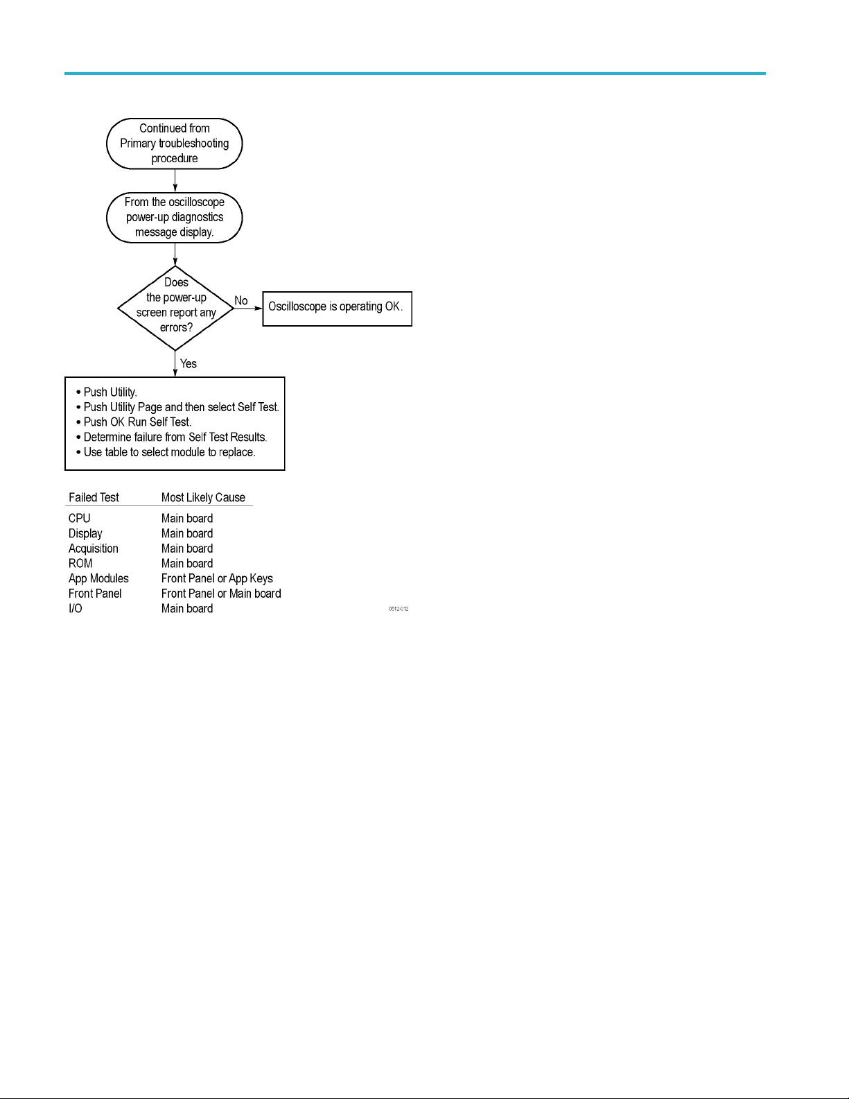
Troubleshooting Procedure
The f
troubleshoot an instrument failure. Begin with the Primary troubleshooting
procedure flowchart. (See Figure 4.)
WAR N ING. Before removing the cabinet, disconnect the power cord from the line
voltage source. Failure to do so could cause serious injury or death.
5.)
ollowing figures are troubleshooting procedure flowcharts. Use them to
CAUTION. When you operate the instrument with the cabinet removed, the system
fan will not operate. You must provide an external fan to cool the interior of the
instrument. Failure to do so could cause instrument damage.
MDO3000 Series Mixed Domain Oscilloscopes Service Manual 13

Maintenance
Figure 4: Primary troubleshooting procedure
14 MDO3000 Series Mixed Domain Oscilloscopes Service Manual

Maintenance
Figure 5: AC power supply troubleshooting procedure
NOTE. The test point voltages are printed on the Main board. The +12 V test
point is on the upper right-hand corner of the board.
MDO3000 Series Mixed Domain Oscilloscopes Service Manual 15
Maintenance
e 6: Module isolation troubleshooting procedure
Figur
16 MDO3000 Series Mixed Domain Oscilloscopes Service Manual

Unpacking and Repacking Instructions
This section contains the information needed to unpack the oscilloscope and
repack it for shipment or storage.
Maintenance
Unpacking
Repacking
The oscilloscope and its standard accessories are carefully packed at the factory in
a shipping carton. If, upon receipt, damage to the shipping carton is evident, tell
the shipper. Tektronix, Inc. is not responsible for damage caused during shipping.
If you have not already done so, carefully remove the oscilloscope and its
accessories from the shipping carton and inspect them for damage. Save the
shipping carton for repacking or storage.
Use a corrugated cardboard shipping carton having a test strength of at least 275
pounds (125 kg) and with an inside dimension at least six inches (15.25 cm)
greater than the instrument dimensions.
If the instrument is being shipped to a Tektronix Service Center, enclose the
following information:
The owner’s address
Name and phone number of a contact person
Type and serial number of the instrument
on for returning
Reas
A complete description of the service required
torage
S
Seal the shipping carton with an industrial stapler or strapping tape.
Mark the address of the Tektronix Service Center and also your own return address
on the shipping carton in two prominent locations. See www.tektronix.com/service
to find a service center near you.
The oscilloscope should be stored in a clean, dry e nvironment. The following
environmental characteristics apply for both shipping and storage:
Temperature range: –40 °F to +160 °F (–40 °C to +71 ° C)
Altitude: To 39,370 feet (12,000 m )
See the Tektronix MDO3000 Series Mixed Domain Oscilloscopes Specifications
and Performance Verification Technical Reference for a complete listing of the
environmental specifications.
MDO3000 Series Mixed Domain Oscilloscopes Service Manual 17

Maintenance
18 MDO3000 Series Mixed Domain Oscilloscopes Service Manual

Replaceable Parts List
This chapter contains a list of the replaceable modules for these oscilloscopes.
Use this list to identify and order replacement parts.
Parts Ordering Information
Replacement parts are available through your local Tektronix field office or
representative.
Changes to Tektronix products are sometimes made to accommoda t e improved
components as they become available and to give you the benefit of the latest
improvements. Therefore, when ordering parts, it is important to include the
followin
If you order a part that has been replaced with a different or improved part, your
local Tektronix field office or representative will contact you concerning any
change in part number.
ginformationinyourorder:
Part number (see Part Number Revision Level below)
Instrument type or model number
Instrument serial number
Instrument modification number, if applicable
Part Number Revision
Level
Change information, if any, is located at the rear of this manual.
tronix part numbers contain two digits that show the revision level of the
Tek
part. For some parts in this manual, you will find the letters XX in place of the
revision level number.
When you order parts, Tektronix will provide you with the most current part for
your product type, serial number, and modification (if applicable). At the time of
your order, Tektronix will determine the part number revision level needed for
your product, based on the information you provide.
MDO3000 Series Mixed Domain Oscilloscopes Service Manual 19

Replaceable Parts List
Module Servicing
Modules can be s
local Tektronix service center or representative for repair assistance.
Module exchange. In some cases you may exchange your module for a
remanufactured module. These modules cost significantly less than new modules
and meet the same factory specifications. For more information about the module
exchange pr
Module repair and return. You may ship your module to us for repair, after which
we will return it to you.
New modules. You may purchase replacement modules in the same way as other
replacem
ent parts.
erviced by selecting one of the next three options. Contact your
ogram, call 1-800-833-9200, extension 2.
20 MDO3000 Series Mixed Domain Oscilloscopes Service Manual

Using the Replaceable Parts List
This section contains a list of the mechanical and/or electrical components that
are replaceable for the instrument. Use this list to identify and order replacement
parts. The following table describes each column in the parts list.
Table 3: Parts list column descriptions
Column Column Name Description
1
2 Tektronix Part
3 and 4
5
6
Figure & Index
Number
Number
Serial Number Column three indicates the serial number at which the part was first effective. Column four
Qty This indicates the quantity of parts used.
Name & Description An item name is separated from the description by a colon (:). Because of space limitations,
Items in this section are referenced by figure and index numbers to the exploded view
illustrations that follow the list.
Use this part number when ordering replacement parts from Tektronix.
indicates the serial number at which the part was discontinued. No entries indicates the
part is good for all serial numbers.
an item name may sometimes appear as incomplete. Use the U.S. Federal Catalog handbook
H6-1 for further item name identification.
Replaceable Parts List
Abbreviations
Exploded Views
Abbreviations conform to American National Standard ANSI Y1.1-1972.
res 7 through 9 on the following pages show the module-level exploded views
Figu
of the oscilloscopes. Each exploded view is indexed by the numbers in the figure.
MDO3000 Series Mixed Domain Oscilloscopes Service Manual 21

Replaceable Parts List
Table 4: Front p
Fig. &
index
number
anel assembly
Tektronix
part number
Serial
no.
effective
Serial no.
discont’d Qty Name & description
7- FRONT PANEL ASSEMBLY
-1
-2 366-0855-XX 2
-3 366-0867-XX 1
-4 358-0883-XX 1
-5
-6 366-0859-XX 6
-7
-8
-9 260-2857-XX 1
-10 407-5259-XX 1
-11 211-1273-XX 19
-12 260-2889-XX 1
-13 407-2567-XX 1
-14 260-2971-XX 1
050-3815-XX 1
050-3814-XX 1
366-0865-XX 1
366-0860-XX 6
335-2664-XX 1
335-2665-XX 1
335-2666-XX 1
335-2667-XX 1
335-2668-XX 1
335-2669-XX 1
335-2670-XX 1
335-2671-XX 1
335-2672-XX 1
335-2673-XX 1
PARTS REPLACEMENT KIT; 2 CH FRONT PANEL ASSEMBLY; INCLUDES THE
FOLLOWING PARTS:
FIGURE NUMBE
PARTS REPL A
FOLLOWING PARTS:
FIGURE NUMBERS 9, 10, 14, 15 and 21
ASSEMBLY, KNOB: 0.925 DIAMETER, SOFT TOUCH
KNOB, SHUTTLE; ASSEMBLY
BUSHING (JOG SHUTTLE KNOB)
KNOB ASSEMBLY, JOG
ASSEMBLY, KNOB: 0.470 DIAMETER, SOFT TOUCH
ASSEMBLY, KNOB: 0.685 DIAMETER, SOFT TOUCH
LABEL. FRONT PANEL, OVERLAY, FRENCH
LABEL. FRONT PANEL, OVERLAY, ITALIAN
LABEL. FRONT PANEL, OVERLAY, GERMAN
LABEL. FRONT PANEL, OVERLAY, SPANISH
LABEL. FRONT PANEL, OVERLAY, JAPANESE
LABEL. FRONT PANEL, OVERLAY, PORTUGUESE
LABEL. FRONT PANEL, OVERLAY, SIMPLIFIED CHINESE
LABEL. FRONT PANEL, OVERLAY, TRADITIONAL CHINESE
LABEL. FRONT PANEL, OVERLAY, KOREAN
LABEL FRONT PANEL OVERLAY, RUSSIAN
SWITCH, KEYPAD, ELASTOMERIC, POWER
BRACKET, SUPPORT: POWER SWITCH
SCREW, PT, K35-1.57, PAN HEAD, STL, ZNPL, T-15 TORX DRIVE
------DISTRIBUTIONOFTHE211-1273-XX SCREWS - - - - - -
2 screws attach the Power switch and bracket to the front case assembly.
2 screws attach the Utility switch and bracket to the front case assembly.
10 screws attach the Front panel assembly to the front case assembly – with contact springs
#17).
(
screws across the bottom of the Front panel assembly attach it to the front case assembly
5
– without contact springs.
SWITCH, KEYPAD, ELASTOMERIC, UTILITY
BRACKET, SUPPORT, UTILITY SWITCH
SWITCH, KEYPAD, ELASTOMERIC, FRONT PANEL
RS 9, 10, 14, 15 and 21
CEMENT KIT; 4 CH FRONT PANEL ASSEMBLY; INCLUDES THE
22 MDO3000 Series Mixed Domain Oscilloscopes Service Manual

Replaceable Parts List
Fig. &
index
number
Tektronix
part number
Serial
no.
effective
Serial n o.
discont’d Qty Name & description
7- FRONT PANEL ASSEMBLY
-15 105-1176-XX 1
-16
-17 131-8139-X
-18 351-1109-0
-19 213-1149-X
-20 259-0212-
-21 200-5301-
-22 200-5052
878-0789-XX 1
878-0764-XX 1
X
1
X
XX
XX
-XX
10
2
2
1
1
1
ACTUATOR, SWITCH, 10 KEY
CIRCUIT BOARD ASSEMBLY, FRONT PANEL, 2 CH
CIRCUIT BOARD ASSEMBLY, FRONT PANEL, 4 CH
CONTACT, SPRING: FRONT PANEL ELEC
GUIDE, KEY; POLY, BAYBLEND FR-110
SCREW, TPG, TF; 2-28 X.5, PLASTITE, FLAT HEAD, PHILLIPS, STL, ZNPL
CIRCUIT, FLEX; 10 KEY
COVER; OPTION KEY DOOR, PC/ABS, FR110, SILVER GRAY
COVER, FRONT PROTECTIVE
MDO3000 Series Mixed Domain Oscilloscopes Service Manual 23

Replaceable Parts List
Figure 7: Exploded view, front panel assembly
24 MDO3000 Series Mixed Domain Oscilloscopes Service Manual

Replaceable Parts List
Table 5: Displa
y, analog board, and main board
Figure
and
index
no.
Tektronix
part no.
Serial
no.
effective
Serial
no.
discont'd Qty. Name and description
8-
-1 850-0252-XX 1
-2 441-2740-XX 1
-3 211-1272-XX 43
-4 878-0872-XX 1
-5
-6 174-6347-XX 1
-7
-8 211-1275-XX 8
-9 878-0763-XX 1
-10 351-1130-XX 1
-11 129-1693-XX 1
-12 348-1863-XX 1
-13
-14 174-6343-XX 1
-15 131-6643-XX 1
-16 131-7622-XX 1
-17 407-5324-XX 1
-18 131-6521-XX 1
-19 174-5411-XX 1
211-1273-XX 8
174-6284-XX 1
878-0801-XX 1
878-0784-XX 1
878-0803-XX 1
878-0802-XX 1
DISPLAY, ANALOG BOARD & MAIN BOARD
FRAME ASSEMBLY, DISPLAY: LCD
CHASSIS ASSEMBLY, FRONT
SCREW, MACHINE: 6–32 x 0.250, PNH, STL, ZNPL, T-15 TORX DRIVE
- - - - - - DISTRIBUTION OF THE 211-1272-XX SCREWS - - - - - -
9 screws attach the LCD assembly to the front chassis.
15 screws attach the Main board assembly to the front chassis.
6 screws attach the Analog board assembly to the front chassis.
12 screws attach the rear chassis to the front chassis: 4 across the top flange of the rear
chassis,2oneachsideflange, and 4 across the bottom flange of the front chassis.
1 screw attaches the ground jack to the front chassis.
MEZZANINE BD. Return the instrument to Tektronix for service.
SCREW, PT, K35–1.57, PAN HEAD, STL, ZNPL, T-15 TORX DRIVE
CABLE; FRONT PANEL TO MEZZANINE
CABLE, POWER SUPPLY OUTPUT
SCREW
MAIN BOARD ASSEMBLY. Return the instrument to Tektronix for service. The Main board
and the Attenuator board must be calibrated together if either is found defective.
GUIDE, PROBE
SPACER, POST
EMI GASKET
ATTENUATOR BD, 500 MHz, 2 CH. Return the instrument to Tektronix for service.
The Main board and the Attenuator board must be calibrated together if either is found
defective.
ATTENUATOR BD, 500 MHz, 4 CH. Return the instrument to Tektronix for service.
The Main board and the Attenuator board must be calibrated together if either is found
defective.
ATTENUATOR BD, 1 GHz, 2 CH. Return the instrument to Tektronix for service. The Main
board and the Attenuator board must be calibrated together if either is found defective.
ATTENUATOR BD, 1 GHz, 4 CH. Return the instrument to Tektronix for service. The Main
board and the Attenuator board must be calibrated together if either is found defective.
CABLE, DISPLAY
CONTACT, ELEC: GROUNDING, ELECTROLESS NICKEL PLATE
CONN, RECEPT; GROUND JACK
BRACKET, USB
EMI CLIP
CABLE, USB HOST
MDO3000 Series Mixed Domain Oscilloscopes Service Manual 25

Replaceable Parts List
Figure 8: Display, analog board, and main board assembly
26 MDO3000 Series Mixed Domain Oscilloscopes Service Manual

Replaceable Parts List
Table 6: Rear ch
assis and connecting modules
Figure
and
index
no.
Tektronix
part no.
Serial
no.
effective
Serial
no.
discont'd Qty. Name and description
9-
-1 174-6286-XX 1
-2 211-1272-XX 13
-3 119-7086-XX 1
-4 441-2741-XX 1
-5
-6 211-1275-XX 4
-7
-8 335-3149-XX 1
-9 343-1736-XX 1
-10 131-6643-XX 1
-11 878-0761-XX 1
-12 119-8180-XX 1
-13 119-8042-XX 1
065-0965-XX 1
214-3903-XX 2
REAR CHASSIS, POWER SUPPLY, I/O BOARD
CABLE, AC INPUT
SCREW, MACHINE: 6–32 x 0.250, PNH, STL, ZNPL, T-15 TORX DRIVE
- - - - - - DISTRIBUTION OF THE 211-1272-XX SCREWS - - - - - -
3 screws attach the I/O board to the rear chassis.
2 screws attach the line filter to the rear chassis.
4 screws attach the system fan (#12) to the rear chassis.
4 screws attach the rear chassis to the front chassis.
FILTER, EMI, AC LINE CONNECTOR
CHASSIS ASSEMBLY, REAR
REAR CASE ASSEMBLY
SCREW
- - - - - - DISTRIBUTION OF THE 211-1275-XX SCREWS - - - - - -
4 screws attach the Power supply circuit board to the rear chassis.
SCREW, JACK; 4-40 X 0.312 LONG, 0.188 H HEX HEAD STAND OFF
LABEL, IO, REAR
CABLE CLAMP
CONTACT, ELEC: GROUNDING, ELECTROLESS NICKEL PLATE
I/O BOARD ASSEMBLY
SYSTEM FAN ASSEMBLY, 120 MM, TUBEAXIAL, 12 VDC; SAFETY CONTROLLED,
WITH BRACKET
POWER SUPPLY; AC-DC; SAFETY CONTROLLED
MDO3000 Series Mixed Domain Oscilloscopes Service Manual 27

Replaceable Parts List
Figure 9: Rear chassis and connecting modules
28 MDO3000 Series Mixed Domain Oscilloscopes Service Manual
 Loading...