

Page 1

Page 2

Page 3

Instruction Manual
MCF Series
Video Transmission System
071-0229-02
*P071022902*
071022902
Page 4

Page 5

Installation and Service
MCF Series
Video Transmission System
071-0229-02
First Printing: November, 1995
Revised Printing: June, 1999
Page 6

Contacting Tektronix
Voice Fax Addresses Web Site
Customer
Support
Product,
Service, Sales
Information
North America (800) 547-8949 (530) 478-3181 Tektronix, Inc.
Elsewhere Distributor or sales office from which
equipment was purchased.
North America (800) 547-8949 (503) 627-7275 Tektronix, Inc.
Europe 44 (10) 1628 40 3300 44 (0)1628 40 3301
Asia (852) 2585-6688 (852) 2802-2996
Japan 81 (3) 5992 0621 81 (3) 5992 9377
Latin America (305) 477-5488 (305) 477-5385
Copyright © Tektronix, Inc. All rights reserved.
This document may not be copied, in whole or in part, or otherwise reproduced, except as specifically
permitted under U.S. copyright law, without the prior written consent of Tektronix, Inc., P.O. Box 1000,
Wilsonville, Oregon 97070-1000. TEKTRONIX is a registered trademark and Grass Valley is a trademark of Tektronix, Inc. All registered trademarks and trademarks are property of their respective holders. Tektronix products are covered by U.S. and foreign patents, issued and pending. Product options
and specifications subject to change without notice. The information in this manual is furnished for informational use only, is subject to change without notice, and should not be construed as a commitment
by Tektronix, Inc. Tektronix assumes no responsibility or liability for any errors or inaccuracies that
may appear in this publication.
Tektronix Grass Valley Products
http://www.tektronix.com
P.O. Box 1114
Grass Valley, CA 95945, USA
http://www.tektronix.com
Video and Networking Division
P.O. Box 500
M.S. 58-965
Beaverton, OR 97077-0001, USA
Page 7

Contents
Safety Terms and Symbols. . . . . . . . . . . . . . . . . . . . . . . . . . . . . . . . . . . . . . . . . . . . . . xi
Terms in This Manual . . . . . . . . . . . . . . . . . . . . . . . . . . . . . . . . . . . . . . . . . . . . . . . . xi
Terms on the Product . . . . . . . . . . . . . . . . . . . . . . . . . . . . . . . . . . . . . . . . . . . . . . . . xi
Symbols on the Product . . . . . . . . . . . . . . . . . . . . . . . . . . . . . . . . . . . . . . . . . . . . . . xii
Warnings . . . . . . . . . . . . . . . . . . . . . . . . . . . . . . . . . . . . . . . . . . . . . . . . . . . . . . . . . . . . xii
Cautions . . . . . . . . . . . . . . . . . . . . . . . . . . . . . . . . . . . . . . . . . . . . . . . . . . . . . . . . . . . . xiii
Section 1 — System Description and Specifications
Introduction . . . . . . . . . . . . . . . . . . . . . . . . . . . . . . . . . . . . . . . . . . . . . . . . . . . . . . . . . 1-1
System Description . . . . . . . . . . . . . . . . . . . . . . . . . . . . . . . . . . . . . . . . . . . . . . . . . . . 1-1
MCF Frames . . . . . . . . . . . . . . . . . . . . . . . . . . . . . . . . . . . . . . . . . . . . . . . . . . . . . . . 1-2
Six Rack Unit Frame (10.5 in. or 267 mm high) . . . . . . . . . . . . . . . . . . . . . . . . 1-5
Two Rack Unit Frame (3.5 in. or 89 mm high). . . . . . . . . . . . . . . . . . . . . . . . . 1-7
Fiber Modules . . . . . . . . . . . . . . . . . . . . . . . . . . . . . . . . . . . . . . . . . . . . . . . . . . . . . 1-9
Combined Video/Audio Modules . . . . . . . . . . . . . . . . . . . . . . . . . . . . . . . . . . . 1-10
Video Modules Input and Output . . . . . . . . . . . . . . . . . . . . . . . . . . . . . . . . . . . 1-10
Audio Modules Input and Output . . . . . . . . . . . . . . . . . . . . . . . . . . . . . . . . . . . 1-10
Serial Digital Modules . . . . . . . . . . . . . . . . . . . . . . . . . . . . . . . . . . . . . . . . . . . . . 1-10
Video/Audio Diplexer Modules Input and Output . . . . . . . . . . . . . . . . . . . . 1-11
Backplanes . . . . . . . . . . . . . . . . . . . . . . . . . . . . . . . . . . . . . . . . . . . . . . . . . . . . . . . 1-11
Backplane for the 6 RU Frame . . . . . . . . . . . . . . . . . . . . . . . . . . . . . . . . . . . . . 1-11
Backplane for the 2 RU Frame . . . . . . . . . . . . . . . . . . . . . . . . . . . . . . . . . . . . . 1-12
Fan Assembly (6 RU only). . . . . . . . . . . . . . . . . . . . . . . . . . . . . . . . . . . . . . . . . . 1-13
Deflector Assembly (6 RU only) . . . . . . . . . . . . . . . . . . . . . . . . . . . . . . . . . . . . . 1-14
Physical Specifications . . . . . . . . . . . . . . . . . . . . . . . . . . . . . . . . . . . . . . . . . . . . . . . 1-15
Power Specifications. . . . . . . . . . . . . . . . . . . . . . . . . . . . . . . . . . . . . . . . . . . . . . . . . 1-15
Regulatory Compliance . . . . . . . . . . . . . . . . . . . . . . . . . . . . . . . . . . . . . . . . . . . . . . 1-16
Environmental Criteria. . . . . . . . . . . . . . . . . . . . . . . . . . . . . . . . . . . . . . . . . . . . . . . 1-16
Alarm Indicators . . . . . . . . . . . . . . . . . . . . . . . . . . . . . . . . . . . . . . . . . . . . . . . . . . . . 1-16
Functional Specifications . . . . . . . . . . . . . . . . . . . . . . . . . . . . . . . . . . . . . . . . . . . . . 1-19
Terms Used . . . . . . . . . . . . . . . . . . . . . . . . . . . . . . . . . . . . . . . . . . . . . . . . . . . . . . . . 1-23
Contents
Section 2 — Installation
Installation Overview . . . . . . . . . . . . . . . . . . . . . . . . . . . . . . . . . . . . . . . . . . . . . . . 2-1
Pre-Installation Planning . . . . . . . . . . . . . . . . . . . . . . . . . . . . . . . . . . . . . . . . . . . . . . 2-1
Calculating Optical Fiber Path Loss Budget . . . . . . . . . . . . . . . . . . . . . . . . . . . . 2-2
Space Planning. . . . . . . . . . . . . . . . . . . . . . . . . . . . . . . . . . . . . . . . . . . . . . . . . . . . . 2-3
Power Requirements. . . . . . . . . . . . . . . . . . . . . . . . . . . . . . . . . . . . . . . . . . . . . . . . 2-3
Heat Considerations . . . . . . . . . . . . . . . . . . . . . . . . . . . . . . . . . . . . . . . . . . . . . . . . 2-3
Humidity. . . . . . . . . . . . . . . . . . . . . . . . . . . . . . . . . . . . . . . . . . . . . . . . . . . . . . . . . . 2-3
Unpacking the Equipment. . . . . . . . . . . . . . . . . . . . . . . . . . . . . . . . . . . . . . . . . . . . . 2-4
Receiving Inspection . . . . . . . . . . . . . . . . . . . . . . . . . . . . . . . . . . . . . . . . . . . . . . . . 2-4
Unpacking. . . . . . . . . . . . . . . . . . . . . . . . . . . . . . . . . . . . . . . . . . . . . . . . . . . . . . . . . 2-4
Equipment Inspection. . . . . . . . . . . . . . . . . . . . . . . . . . . . . . . . . . . . . . . . . . . . . . . 2-5
Test Equipment and Tools Required . . . . . . . . . . . . . . . . . . . . . . . . . . . . . . . . . . 2-5
Installation of a 6 RU Frame in the Equipment Rack. . . . . . . . . . . . . . . . . . . . . . . 2-5
MCF Installation and Service iii
Page 8

Contents
Installing a 6 RU Frame . . . . . . . . . . . . . . . . . . . . . . . . . . . . . . . . . . . . . . . . . . . . . . 2-6
Installing Multiple 6 RU Frames. . . . . . . . . . . . . . . . . . . . . . . . . . . . . . . . . . . . . . . 2-7
Maximum 6RU Frame Configuration . . . . . . . . . . . . . . . . . . . . . . . . . . . . . . . . 2-7
Installation of a 2 RU Frame in the Equipment Rack . . . . . . . . . . . . . . . . . . . . . . . 2-9
Installing a 2 RU Frame . . . . . . . . . . . . . . . . . . . . . . . . . . . . . . . . . . . . . . . . . . . . . . 2-9
Installing Multiple 2 RU Frames. . . . . . . . . . . . . . . . . . . . . . . . . . . . . . . . . . . . . . 2-10
Making Frame Connections . . . . . . . . . . . . . . . . . . . . . . . . . . . . . . . . . . . . . . . . . 2-10
Backplane for the 2 RU Frame. . . . . . . . . . . . . . . . . . . . . . . . . . . . . . . . . . . . . . . . 2-11
Grounding the Frame. . . . . . . . . . . . . . . . . . . . . . . . . . . . . . . . . . . . . . . . . . . . . . . . . 2-11
Making Alarm Connections . . . . . . . . . . . . . . . . . . . . . . . . . . . . . . . . . . . . . . . . . . . 2-13
Making Power Connections . . . . . . . . . . . . . . . . . . . . . . . . . . . . . . . . . . . . . . . . . . . 2-14
AC Power Connections . . . . . . . . . . . . . . . . . . . . . . . . . . . . . . . . . . . . . . . . . . . . . 2-15
Six RU Frame . . . . . . . . . . . . . . . . . . . . . . . . . . . . . . . . . . . . . . . . . . . . . . . . . . . . 2-15
Two Rack Unit Frame . . . . . . . . . . . . . . . . . . . . . . . . . . . . . . . . . . . . . . . . . . . . . 2-16
DC Power Connections . . . . . . . . . . . . . . . . . . . . . . . . . . . . . . . . . . . . . . . . . . . . . 2-16
DC Power for the 6 RU Frame. . . . . . . . . . . . . . . . . . . . . . . . . . . . . . . . . . . . . . 2-16
DC Power for the 2 RU Frame. . . . . . . . . . . . . . . . . . . . . . . . . . . . . . . . . . . . . . 2-17
Fan Power Connection . . . . . . . . . . . . . . . . . . . . . . . . . . . . . . . . . . . . . . . . . . . . . . 2-18
Fan for the 6 RU Frame. . . . . . . . . . . . . . . . . . . . . . . . . . . . . . . . . . . . . . . . . . . . 2-18
Making Signal Connections . . . . . . . . . . . . . . . . . . . . . . . . . . . . . . . . . . . . . . . . . . . 2-19
Administration Port Connection . . . . . . . . . . . . . . . . . . . . . . . . . . . . . . . . . . . . . 2-19
RS-485 Communication . . . . . . . . . . . . . . . . . . . . . . . . . . . . . . . . . . . . . . . . . . . 2-20
RS-232 Communication . . . . . . . . . . . . . . . . . . . . . . . . . . . . . . . . . . . . . . . . . . . 2-23
Craft Port Connection. . . . . . . . . . . . . . . . . . . . . . . . . . . . . . . . . . . . . . . . . . . . . . . 2-25
Video Connections . . . . . . . . . . . . . . . . . . . . . . . . . . . . . . . . . . . . . . . . . . . . . . . . . 2-28
Serial Digital Video Connections . . . . . . . . . . . . . . . . . . . . . . . . . . . . . . . . . . . 2-28
Other Video Connections. . . . . . . . . . . . . . . . . . . . . . . . . . . . . . . . . . . . . . . . . . 2-29
NRZ and NRZI Modes and Compatibility . . . . . . . . . . . . . . . . . . . . . . . . . . . . . 2-30
Incompatible Systems . . . . . . . . . . . . . . . . . . . . . . . . . . . . . . . . . . . . . . . . . . . . . 2-30
Compatible Systems . . . . . . . . . . . . . . . . . . . . . . . . . . . . . . . . . . . . . . . . . . . . . . 2-30
Modification of 066039-00 and -01 Transmitters. . . . . . . . . . . . . . . . . . . . . . . 2-32
Modification of 066039-10, -11, and -30 Transmitters . . . . . . . . . . . . . . . . . . 2-33
Modification of 066040-00, -01, -10, -20, and -21 Receivers . . . . . . . . . . . . . . 2-34
160293-00 Transmitter NRZ Jumper Setting . . . . . . . . . . . . . . . . . . . . . . . . . . 2-35
Video Connections at Receiver Frame . . . . . . . . . . . . . . . . . . . . . . . . . . . . . . . . . 2-35
Audio Connections . . . . . . . . . . . . . . . . . . . . . . . . . . . . . . . . . . . . . . . . . . . . . . . . . 2-36
Audio Connector Orientation for the 6 RU Frame . . . . . . . . . . . . . . . . . . . . 2-38
Audio Connector Orientation for the 2 RU Frame . . . . . . . . . . . . . . . . . . . . 2-38
Audio Clip Level . . . . . . . . . . . . . . . . . . . . . . . . . . . . . . . . . . . . . . . . . . . . . . . . . 2-39
Fiber-Optic Connection . . . . . . . . . . . . . . . . . . . . . . . . . . . . . . . . . . . . . . . . . . . . . 2-40
Fiber Module Settings . . . . . . . . . . . . . . . . . . . . . . . . . . . . . . . . . . . . . . . . . . . . . . . . 2-41
Craft Port Parity and Baud Rate . . . . . . . . . . . . . . . . . . . . . . . . . . . . . . . . . . . . . . 2-42
Transmitter or Receiver Frame Address . . . . . . . . . . . . . . . . . . . . . . . . . . . . . . . 2-44
Slave Function (Transmitter Module only) . . . . . . . . . . . . . . . . . . . . . . . . . . . . . 2-45
Boot Function (Transmitter/Receiver Module) . . . . . . . . . . . . . . . . . . . . . . . . . 2-45
Video Input and Output Module Settings . . . . . . . . . . . . . . . . . . . . . . . . . . . . . . . 2-46
Cable Equalization . . . . . . . . . . . . . . . . . . . . . . . . . . . . . . . . . . . . . . . . . . . . . . . 2-46
Video Input Module Cable Equalization . . . . . . . . . . . . . . . . . . . . . . . . . . . . . 2-46
Video Output Module Cable Equalization . . . . . . . . . . . . . . . . . . . . . . . . . . . 2-48
Installation of Hybrid Boards . . . . . . . . . . . . . . . . . . . . . . . . . . . . . . . . . . . . . . 2-49
Video Signal Termination . . . . . . . . . . . . . . . . . . . . . . . . . . . . . . . . . . . . . . . . . . . 2-50
Video Squelch Jumper . . . . . . . . . . . . . . . . . . . . . . . . . . . . . . . . . . . . . . . . . . . . . . 2-50
DC Restore Jumper . . . . . . . . . . . . . . . . . . . . . . . . . . . . . . . . . . . . . . . . . . . . . . . . . 2-51
iv MCF Installation and Service
Page 9

Video Input DC Restore Jumper . . . . . . . . . . . . . . . . . . . . . . . . . . . . . . . . . . . 2-52
Video Output DC Restore Jumper. . . . . . . . . . . . . . . . . . . . . . . . . . . . . . . . . . 2-52
Audio Input Module Setting . . . . . . . . . . . . . . . . . . . . . . . . . . . . . . . . . . . . . . . . . . 2-53
Input Audio Attenuation . . . . . . . . . . . . . . . . . . . . . . . . . . . . . . . . . . . . . . . . . . . 2-53
Combined Video/Audio Module Settings . . . . . . . . . . . . . . . . . . . . . . . . . . . . . . 2-54
Input Cable Equalization . . . . . . . . . . . . . . . . . . . . . . . . . . . . . . . . . . . . . . . . . . . 2-54
Output Cable Equalization. . . . . . . . . . . . . . . . . . . . . . . . . . . . . . . . . . . . . . . . . . 2-56
Video Signal Termination. . . . . . . . . . . . . . . . . . . . . . . . . . . . . . . . . . . . . . . . . . . 2-57
DC Restore Jumper . . . . . . . . . . . . . . . . . . . . . . . . . . . . . . . . . . . . . . . . . . . . . . . . 2-58
Video/Audio Input DC Restore Jumper . . . . . . . . . . . . . . . . . . . . . . . . . . . . 2-58
Video/Audio Output DC Restore Jumper. . . . . . . . . . . . . . . . . . . . . . . . . . . 2-60
Video Clamp Jumper . . . . . . . . . . . . . . . . . . . . . . . . . . . . . . . . . . . . . . . . . . . . . . 2-60
Video/Audio Input Video Clamp Jumper. . . . . . . . . . . . . . . . . . . . . . . . . . . 2-61
Video/Audio Output Video Clamp Jumper . . . . . . . . . . . . . . . . . . . . . . . . . 2-62
Audio Input Impedance Selection . . . . . . . . . . . . . . . . . . . . . . . . . . . . . . . . . . . 2-62
Audio Attenuation Clip Selection . . . . . . . . . . . . . . . . . . . . . . . . . . . . . . . . . . . . 2-63
Serial Digital Module Settings. . . . . . . . . . . . . . . . . . . . . . . . . . . . . . . . . . . . . . . . . 2-66
Cable Equalization. . . . . . . . . . . . . . . . . . . . . . . . . . . . . . . . . . . . . . . . . . . . . . . . . 2-66
270/143 Mode Selection on the Input Module . . . . . . . . . . . . . . . . . . . . . . . . . 2-66
MCF Six Slot Mode Selection for Both Input and Output . . . . . . . . . . . . . . . . 2-67
System/Backplane Mode Selection on the Output Module . . . . . . . . . . . . . . 2-69
Video/Audio Diplexer Module Settings . . . . . . . . . . . . . . . . . . . . . . . . . . . . . . . . 2-70
Video Cable Equalization. . . . . . . . . . . . . . . . . . . . . . . . . . . . . . . . . . . . . . . . . . . 2-70
Output Cable Equalization. . . . . . . . . . . . . . . . . . . . . . . . . . . . . . . . . . . . . . . . . . 2-71
Video Signal Termination. . . . . . . . . . . . . . . . . . . . . . . . . . . . . . . . . . . . . . . . . . . 2-72
DC Restore Jumpers . . . . . . . . . . . . . . . . . . . . . . . . . . . . . . . . . . . . . . . . . . . . . . . 2-73
Diplexer Input DC Restore Jumper . . . . . . . . . . . . . . . . . . . . . . . . . . . . . . . . . 2-74
Diplexer Output DC Restore Jumper . . . . . . . . . . . . . . . . . . . . . . . . . . . . . . . 2-74
Impedance Selection . . . . . . . . . . . . . . . . . . . . . . . . . . . . . . . . . . . . . . . . . . . . . . . 2-75
Audio Gain Selection . . . . . . . . . . . . . . . . . . . . . . . . . . . . . . . . . . . . . . . . . . . . . . 2-76
Ramp Enable/Disable on DIP Switch 3 for Input Module . . . . . . . . . . . . . . . 2-78
Subcarrier Enable/Disable on DIP Switch 3 for Input Module . . . . . . . . . . . 2-79
OC-3/MCF Selection for Both Input and Output Modules . . . . . . . . . . . . . . 2-79
MCF Six Slot Mode Selection for Both Input and Output Modules. . . . . . . . 2-80
Mute Video Disable/Enable Selection on the Output Module. . . . . . . . . . . . 2-82
Mute Audio Disable/Enable Selection on the Output Module . . . . . . . . . . . 2-83
Filtered/Diplexed Mode Selection on the Output Module. . . . . . . . . . . . . . . 2-83
System/Backplane Mode Selection on the Output Module . . . . . . . . . . . . . . 2-84
Installing Modules in the Frame . . . . . . . . . . . . . . . . . . . . . . . . . . . . . . . . . . . . . . . 2-84
Applying Power . . . . . . . . . . . . . . . . . . . . . . . . . . . . . . . . . . . . . . . . . . . . . . . . . . . . 2-86
Operational Checkout. . . . . . . . . . . . . . . . . . . . . . . . . . . . . . . . . . . . . . . . . . . . . . . . 2-87
Contents
Section 3 — Controls and Indicators
Section Overview . . . . . . . . . . . . . . . . . . . . . . . . . . . . . . . . . . . . . . . . . . . . . . . . . . . . 3-1
Fiber Transmitter. . . . . . . . . . . . . . . . . . . . . . . . . . . . . . . . . . . . . . . . . . . . . . . . . . . . . 3-2
Fiber Receiver . . . . . . . . . . . . . . . . . . . . . . . . . . . . . . . . . . . . . . . . . . . . . . . . . . . . . . . 3-3
Combined Video/Audio Input. . . . . . . . . . . . . . . . . . . . . . . . . . . . . . . . . . . . . . . . . 3-4
Combined Video/Audio Output . . . . . . . . . . . . . . . . . . . . . . . . . . . . . . . . . . . . . . . 3-5
Video Input . . . . . . . . . . . . . . . . . . . . . . . . . . . . . . . . . . . . . . . . . . . . . . . . . . . . . . . . . 3-6
Video Output . . . . . . . . . . . . . . . . . . . . . . . . . . . . . . . . . . . . . . . . . . . . . . . . . . . . . . . . 3-7
Audio Input . . . . . . . . . . . . . . . . . . . . . . . . . . . . . . . . . . . . . . . . . . . . . . . . . . . . . . . . . 3-8
Audio Output . . . . . . . . . . . . . . . . . . . . . . . . . . . . . . . . . . . . . . . . . . . . . . . . . . . . . . . 3-9
MCF Installation and Service v
Page 10

Contents
Serial Digital Input . . . . . . . . . . . . . . . . . . . . . . . . . . . . . . . . . . . . . . . . . . . . . . . . . . . 3-10
Serial Digital Output . . . . . . . . . . . . . . . . . . . . . . . . . . . . . . . . . . . . . . . . . . . . . . . . . 3-11
Video/Audio Diplexer Input . . . . . . . . . . . . . . . . . . . . . . . . . . . . . . . . . . . . . . . . . . 3-12
Video/Audio Diplexer Output . . . . . . . . . . . . . . . . . . . . . . . . . . . . . . . . . . . . . . . . 3-13
Power Supplies . . . . . . . . . . . . . . . . . . . . . . . . . . . . . . . . . . . . . . . . . . . . . . . . . . . . . . 3-14
Section 4 — Functional Description
Functional Overview . . . . . . . . . . . . . . . . . . . . . . . . . . . . . . . . . . . . . . . . . . . . . . . . . . 4-1
System Protocol Description . . . . . . . . . . . . . . . . . . . . . . . . . . . . . . . . . . . . . . . . . . 4-2
Fiber Transmitter Module . . . . . . . . . . . . . . . . . . . . . . . . . . . . . . . . . . . . . . . . . . . . . . 4-4
Timing Generator . . . . . . . . . . . . . . . . . . . . . . . . . . . . . . . . . . . . . . . . . . . . . . . . . . . 4-5
Bus Interface Logic . . . . . . . . . . . . . . . . . . . . . . . . . . . . . . . . . . . . . . . . . . . . . . . . . . 4-5
Multiplexer and Serializer . . . . . . . . . . . . . . . . . . . . . . . . . . . . . . . . . . . . . . . . . . . . 4-5
Laser Driver . . . . . . . . . . . . . . . . . . . . . . . . . . . . . . . . . . . . . . . . . . . . . . . . . . . . . . . . 4-5
Repeater Function . . . . . . . . . . . . . . . . . . . . . . . . . . . . . . . . . . . . . . . . . . . . . . . . . . . 4-5
Laser Temperature Control Loop . . . . . . . . . . . . . . . . . . . . . . . . . . . . . . . . . . . . . . 4-5
Microcontroller . . . . . . . . . . . . . . . . . . . . . . . . . . . . . . . . . . . . . . . . . . . . . . . . . . . . . 4-6
Communication Port Interfaces . . . . . . . . . . . . . . . . . . . . . . . . . . . . . . . . . . . . . . . 4-6
Monitor A to D . . . . . . . . . . . . . . . . . . . . . . . . . . . . . . . . . . . . . . . . . . . . . . . . . . . . . 4-6
Video Sample Oscillator. . . . . . . . . . . . . . . . . . . . . . . . . . . . . . . . . . . . . . . . . . . . . . 4-6
Fiber Receiver Module. . . . . . . . . . . . . . . . . . . . . . . . . . . . . . . . . . . . . . . . . . . . . . . . . 4-7
Optical Preamplifier . . . . . . . . . . . . . . . . . . . . . . . . . . . . . . . . . . . . . . . . . . . . . . . . . 4-7
Gain Block . . . . . . . . . . . . . . . . . . . . . . . . . . . . . . . . . . . . . . . . . . . . . . . . . . . . . . . . . 4-7
Data Low Pass Filter. . . . . . . . . . . . . . . . . . . . . . . . . . . . . . . . . . . . . . . . . . . . . . . . . 4-8
Deserializer and Demultiplexer . . . . . . . . . . . . . . . . . . . . . . . . . . . . . . . . . . . . . . . 4-8
Timing Generator . . . . . . . . . . . . . . . . . . . . . . . . . . . . . . . . . . . . . . . . . . . . . . . . . . . 4-8
Bus Interface Logic . . . . . . . . . . . . . . . . . . . . . . . . . . . . . . . . . . . . . . . . . . . . . . . . . . 4-8
Microcontroller . . . . . . . . . . . . . . . . . . . . . . . . . . . . . . . . . . . . . . . . . . . . . . . . . . . . . 4-8
Communication Port Interfaces . . . . . . . . . . . . . . . . . . . . . . . . . . . . . . . . . . . . . . . 4-9
Combined Video/Audio Input Module . . . . . . . . . . . . . . . . . . . . . . . . . . . . . . . . . 4-10
Video Input Circuit. . . . . . . . . . . . . . . . . . . . . . . . . . . . . . . . . . . . . . . . . . . . . . . . . 4-12
Video Test Ramp Generator . . . . . . . . . . . . . . . . . . . . . . . . . . . . . . . . . . . . . . . . . 4-12
Video Analog-to-Digital Converter . . . . . . . . . . . . . . . . . . . . . . . . . . . . . . . . . . . 4-12
Video Digital Filter . . . . . . . . . . . . . . . . . . . . . . . . . . . . . . . . . . . . . . . . . . . . . . . . . 4-12
Video FIFO Loader . . . . . . . . . . . . . . . . . . . . . . . . . . . . . . . . . . . . . . . . . . . . . . . . . 4-13
Video FIFO. . . . . . . . . . . . . . . . . . . . . . . . . . . . . . . . . . . . . . . . . . . . . . . . . . . . . . . . 4-13
Video Bus Interface. . . . . . . . . . . . . . . . . . . . . . . . . . . . . . . . . . . . . . . . . . . . . . . . . 4-13
Microcontroller . . . . . . . . . . . . . . . . . . . . . . . . . . . . . . . . . . . . . . . . . . . . . . . . . . . . 4-14
Audio Input Circuit . . . . . . . . . . . . . . . . . . . . . . . . . . . . . . . . . . . . . . . . . . . . . . . . 4-14
Audio A/D Converter . . . . . . . . . . . . . . . . . . . . . . . . . . . . . . . . . . . . . . . . . . . . . . 4-14
Audio FIFO Loader. . . . . . . . . . . . . . . . . . . . . . . . . . . . . . . . . . . . . . . . . . . . . . . . . 4-14
Audio FIFO . . . . . . . . . . . . . . . . . . . . . . . . . . . . . . . . . . . . . . . . . . . . . . . . . . . . . . . 4-14
Audio Bus Interface . . . . . . . . . . . . . . . . . . . . . . . . . . . . . . . . . . . . . . . . . . . . . . . . 4-15
Combined Video/Audio Output Module . . . . . . . . . . . . . . . . . . . . . . . . . . . . . . . 4-16
Video Output Bus Interface. . . . . . . . . . . . . . . . . . . . . . . . . . . . . . . . . . . . . . . . . . 4-18
Video FIFO. . . . . . . . . . . . . . . . . . . . . . . . . . . . . . . . . . . . . . . . . . . . . . . . . . . . . . . . 4-18
Video FIFO Unloader . . . . . . . . . . . . . . . . . . . . . . . . . . . . . . . . . . . . . . . . . . . . . . . 4-18
Video Digital Filter . . . . . . . . . . . . . . . . . . . . . . . . . . . . . . . . . . . . . . . . . . . . . . . . . 4-18
Video Digital-to-Analog Converter . . . . . . . . . . . . . . . . . . . . . . . . . . . . . . . . . . . 4-18
Video Output Circuit . . . . . . . . . . . . . . . . . . . . . . . . . . . . . . . . . . . . . . . . . . . . . . . 4-19
Microcontroller . . . . . . . . . . . . . . . . . . . . . . . . . . . . . . . . . . . . . . . . . . . . . . . . . . . . 4-19
Audio Bus Interface . . . . . . . . . . . . . . . . . . . . . . . . . . . . . . . . . . . . . . . . . . . . . . . . 4-19
vi MCF Installation and Service
Page 11

Audio FIFO. . . . . . . . . . . . . . . . . . . . . . . . . . . . . . . . . . . . . . . . . . . . . . . . . . . . . . . 4-19
Audio FIFO Unloader . . . . . . . . . . . . . . . . . . . . . . . . . . . . . . . . . . . . . . . . . . . . . . 4-19
Audio Digital-to-Analog Converter . . . . . . . . . . . . . . . . . . . . . . . . . . . . . . . . . . 4-20
Audio Output Circuitry . . . . . . . . . . . . . . . . . . . . . . . . . . . . . . . . . . . . . . . . . . . . 4-20
Audio Conversion Clock . . . . . . . . . . . . . . . . . . . . . . . . . . . . . . . . . . . . . . . . . . . 4-20
Video Input Module . . . . . . . . . . . . . . . . . . . . . . . . . . . . . . . . . . . . . . . . . . . . . . . . . 4-21
Input Circuit . . . . . . . . . . . . . . . . . . . . . . . . . . . . . . . . . . . . . . . . . . . . . . . . . . . . . . 4-21
Test Ramp Generator . . . . . . . . . . . . . . . . . . . . . . . . . . . . . . . . . . . . . . . . . . . . . . 4-22
Analog-to-Digital Converter . . . . . . . . . . . . . . . . . . . . . . . . . . . . . . . . . . . . . . . . 4-22
Digital Filter . . . . . . . . . . . . . . . . . . . . . . . . . . . . . . . . . . . . . . . . . . . . . . . . . . . . . . 4-22
FIFO Loader . . . . . . . . . . . . . . . . . . . . . . . . . . . . . . . . . . . . . . . . . . . . . . . . . . . . . . 4-22
FIFO . . . . . . . . . . . . . . . . . . . . . . . . . . . . . . . . . . . . . . . . . . . . . . . . . . . . . . . . . . . . . 4-22
Bus Interface . . . . . . . . . . . . . . . . . . . . . . . . . . . . . . . . . . . . . . . . . . . . . . . . . . . . . . 4-23
Processor Clock . . . . . . . . . . . . . . . . . . . . . . . . . . . . . . . . . . . . . . . . . . . . . . . . . . . 4-23
Microcontroller . . . . . . . . . . . . . . . . . . . . . . . . . . . . . . . . . . . . . . . . . . . . . . . . . . . 4-23
Video Output Module . . . . . . . . . . . . . . . . . . . . . . . . . . . . . . . . . . . . . . . . . . . . . . . 4-24
Video Output Bus Interface . . . . . . . . . . . . . . . . . . . . . . . . . . . . . . . . . . . . . . . . . 4-24
FIFO . . . . . . . . . . . . . . . . . . . . . . . . . . . . . . . . . . . . . . . . . . . . . . . . . . . . . . . . . . . . . 4-25
FIFO Unloader . . . . . . . . . . . . . . . . . . . . . . . . . . . . . . . . . . . . . . . . . . . . . . . . . . . . 4-25
Digital Filter . . . . . . . . . . . . . . . . . . . . . . . . . . . . . . . . . . . . . . . . . . . . . . . . . . . . . . 4-25
Digital-to-Analog Converter . . . . . . . . . . . . . . . . . . . . . . . . . . . . . . . . . . . . . . . . 4-25
Output Circuit . . . . . . . . . . . . . . . . . . . . . . . . . . . . . . . . . . . . . . . . . . . . . . . . . . . . 4-25
Processor Clock . . . . . . . . . . . . . . . . . . . . . . . . . . . . . . . . . . . . . . . . . . . . . . . . . . . 4-26
Microcontroller . . . . . . . . . . . . . . . . . . . . . . . . . . . . . . . . . . . . . . . . . . . . . . . . . . . 4-26
Audio Input Module. . . . . . . . . . . . . . . . . . . . . . . . . . . . . . . . . . . . . . . . . . . . . . . . . 4-27
Input Circuit . . . . . . . . . . . . . . . . . . . . . . . . . . . . . . . . . . . . . . . . . . . . . . . . . . . . . . 4-27
A/D Converter. . . . . . . . . . . . . . . . . . . . . . . . . . . . . . . . . . . . . . . . . . . . . . . . . . . . 4-28
FIFO Loader . . . . . . . . . . . . . . . . . . . . . . . . . . . . . . . . . . . . . . . . . . . . . . . . . . . . . . 4-28
FIFO . . . . . . . . . . . . . . . . . . . . . . . . . . . . . . . . . . . . . . . . . . . . . . . . . . . . . . . . . . . . . 4-28
Bus Interface . . . . . . . . . . . . . . . . . . . . . . . . . . . . . . . . . . . . . . . . . . . . . . . . . . . . . . 4-28
Processor Clock . . . . . . . . . . . . . . . . . . . . . . . . . . . . . . . . . . . . . . . . . . . . . . . . . . . 4-28
Microcontroller . . . . . . . . . . . . . . . . . . . . . . . . . . . . . . . . . . . . . . . . . . . . . . . . . . . 4-28
Audio Output Module . . . . . . . . . . . . . . . . . . . . . . . . . . . . . . . . . . . . . . . . . . . . . . . 4-29
Bus Interface Logic . . . . . . . . . . . . . . . . . . . . . . . . . . . . . . . . . . . . . . . . . . . . . . . . 4-29
FIFO . . . . . . . . . . . . . . . . . . . . . . . . . . . . . . . . . . . . . . . . . . . . . . . . . . . . . . . . . . . . . 4-29
FIFO Unloader . . . . . . . . . . . . . . . . . . . . . . . . . . . . . . . . . . . . . . . . . . . . . . . . . . . . 4-30
Processor Interface. . . . . . . . . . . . . . . . . . . . . . . . . . . . . . . . . . . . . . . . . . . . . . . . . 4-30
C-Bit Receiver. . . . . . . . . . . . . . . . . . . . . . . . . . . . . . . . . . . . . . . . . . . . . . . . . . . . . 4-30
D/A Converter. . . . . . . . . . . . . . . . . . . . . . . . . . . . . . . . . . . . . . . . . . . . . . . . . . . . 4-30
Output Drivers. . . . . . . . . . . . . . . . . . . . . . . . . . . . . . . . . . . . . . . . . . . . . . . . . . . . 4-30
Audio Conversion Clock . . . . . . . . . . . . . . . . . . . . . . . . . . . . . . . . . . . . . . . . . . . 4-30
Maintenance Processor . . . . . . . . . . . . . . . . . . . . . . . . . . . . . . . . . . . . . . . . . . . . . 4-30
Serial Digital Input Module. . . . . . . . . . . . . . . . . . . . . . . . . . . . . . . . . . . . . . . . . . . 4-31
Digital Video Input Circuit . . . . . . . . . . . . . . . . . . . . . . . . . . . . . . . . . . . . . . . . . 4-32
FIFO Control. . . . . . . . . . . . . . . . . . . . . . . . . . . . . . . . . . . . . . . . . . . . . . . . . . . . . . 4-32
FIFO (D1/D2 Channel). . . . . . . . . . . . . . . . . . . . . . . . . . . . . . . . . . . . . . . . . . . . . 4-32
MCF Bus Interface . . . . . . . . . . . . . . . . . . . . . . . . . . . . . . . . . . . . . . . . . . . . . . . . . 4-32
Audio Input Interface . . . . . . . . . . . . . . . . . . . . . . . . . . . . . . . . . . . . . . . . . . . . . . 4-33
AES/EBU Decoder . . . . . . . . . . . . . . . . . . . . . . . . . . . . . . . . . . . . . . . . . . . . . . . . 4-33
Audio Deserializer and Buffer. . . . . . . . . . . . . . . . . . . . . . . . . . . . . . . . . . . . . . . 4-33
Audio Data Rate and MCF Bus Timing . . . . . . . . . . . . . . . . . . . . . . . . . . . . . . . 4-34
Buffering and MCF Bus Transfer . . . . . . . . . . . . . . . . . . . . . . . . . . . . . . . . . . . . 4-34
Maintenance Processor . . . . . . . . . . . . . . . . . . . . . . . . . . . . . . . . . . . . . . . . . . . . . 4-34
Contents
MCF Installation and Service vii
Page 12

Contents
Serial Digital Output Module . . . . . . . . . . . . . . . . . . . . . . . . . . . . . . . . . . . . . . . . . . 4-35
Bus Interface . . . . . . . . . . . . . . . . . . . . . . . . . . . . . . . . . . . . . . . . . . . . . . . . . . . . . . 4-36
Video FIFO. . . . . . . . . . . . . . . . . . . . . . . . . . . . . . . . . . . . . . . . . . . . . . . . . . . . . . . . 4-36
FIFO Unloader (Video). . . . . . . . . . . . . . . . . . . . . . . . . . . . . . . . . . . . . . . . . . . . . . 4-36
Serial Digital Video Output Circuit . . . . . . . . . . . . . . . . . . . . . . . . . . . . . . . . . . . 4-36
Audio FIFO . . . . . . . . . . . . . . . . . . . . . . . . . . . . . . . . . . . . . . . . . . . . . . . . . . . . . . . 4-36
FIFO Unloaders (audio channel) . . . . . . . . . . . . . . . . . . . . . . . . . . . . . . . . . . . . . 4-37
Video PLL. . . . . . . . . . . . . . . . . . . . . . . . . . . . . . . . . . . . . . . . . . . . . . . . . . . . . . . . . 4-37
Serial Digital Audio Output Circuit. . . . . . . . . . . . . . . . . . . . . . . . . . . . . . . . . . . 4-37
Audio PLLs . . . . . . . . . . . . . . . . . . . . . . . . . . . . . . . . . . . . . . . . . . . . . . . . . . . . . . . 4-37
Microcontroller . . . . . . . . . . . . . . . . . . . . . . . . . . . . . . . . . . . . . . . . . . . . . . . . . . . . 4-37
Video/Audio Diplexer Input Module. . . . . . . . . . . . . . . . . . . . . . . . . . . . . . . . . . . 4-38
Video Input Processing . . . . . . . . . . . . . . . . . . . . . . . . . . . . . . . . . . . . . . . . . . . . . 4-39
Audio Input Processing . . . . . . . . . . . . . . . . . . . . . . . . . . . . . . . . . . . . . . . . . . . . . 4-39
Analog-to-Digital Converter . . . . . . . . . . . . . . . . . . . . . . . . . . . . . . . . . . . . . . . . . 4-39
Digital Filter . . . . . . . . . . . . . . . . . . . . . . . . . . . . . . . . . . . . . . . . . . . . . . . . . . . . . . . 4-39
FIFO Loader. . . . . . . . . . . . . . . . . . . . . . . . . . . . . . . . . . . . . . . . . . . . . . . . . . . . . . . 4-40
FIFO. . . . . . . . . . . . . . . . . . . . . . . . . . . . . . . . . . . . . . . . . . . . . . . . . . . . . . . . . . . . . . 4-40
Bus Interface . . . . . . . . . . . . . . . . . . . . . . . . . . . . . . . . . . . . . . . . . . . . . . . . . . . . . . 4-40
Processor Clock . . . . . . . . . . . . . . . . . . . . . . . . . . . . . . . . . . . . . . . . . . . . . . . . . . . . 4-40
Microcontroller . . . . . . . . . . . . . . . . . . . . . . . . . . . . . . . . . . . . . . . . . . . . . . . . . . . . 4-40
Video/Audio Diplexer Output Module . . . . . . . . . . . . . . . . . . . . . . . . . . . . . . . . . 4-41
Bus Interface . . . . . . . . . . . . . . . . . . . . . . . . . . . . . . . . . . . . . . . . . . . . . . . . . . . . . . 4-41
FIFO. . . . . . . . . . . . . . . . . . . . . . . . . . . . . . . . . . . . . . . . . . . . . . . . . . . . . . . . . . . . . . 4-42
FIFO Unloader. . . . . . . . . . . . . . . . . . . . . . . . . . . . . . . . . . . . . . . . . . . . . . . . . . . . . 4-42
Digital Filter . . . . . . . . . . . . . . . . . . . . . . . . . . . . . . . . . . . . . . . . . . . . . . . . . . . . . . . 4-42
Digital-to-Analog Converter . . . . . . . . . . . . . . . . . . . . . . . . . . . . . . . . . . . . . . . . . 4-42
Video Output Processing. . . . . . . . . . . . . . . . . . . . . . . . . . . . . . . . . . . . . . . . . . . . 4-42
Audio Output Processing . . . . . . . . . . . . . . . . . . . . . . . . . . . . . . . . . . . . . . . . . . . 4-43
Processor Clock . . . . . . . . . . . . . . . . . . . . . . . . . . . . . . . . . . . . . . . . . . . . . . . . . . . . 4-43
Microcontroller . . . . . . . . . . . . . . . . . . . . . . . . . . . . . . . . . . . . . . . . . . . . . . . . . . . . 4-43
Power Supplies . . . . . . . . . . . . . . . . . . . . . . . . . . . . . . . . . . . . . . . . . . . . . . . . . . . . . . 4-44
Power Supply for the 6 RU Frame . . . . . . . . . . . . . . . . . . . . . . . . . . . . . . . . . . . . 4-44
Power Supply for the 2 RU Frame . . . . . . . . . . . . . . . . . . . . . . . . . . . . . . . . . . . . 4-44
Section 5 — Maintenance & Service
Section Overview . . . . . . . . . . . . . . . . . . . . . . . . . . . . . . . . . . . . . . . . . . . . . . . . . . . . . 5-1
Maintenance . . . . . . . . . . . . . . . . . . . . . . . . . . . . . . . . . . . . . . . . . . . . . . . . . . . . . . . . . 5-1
Air Intake Filter Maintenance . . . . . . . . . . . . . . . . . . . . . . . . . . . . . . . . . . . . . . . . . 5-1
Module Maintenance . . . . . . . . . . . . . . . . . . . . . . . . . . . . . . . . . . . . . . . . . . . . . . . . 5-2
Fiber Transmitter/Receiver Maintenance . . . . . . . . . . . . . . . . . . . . . . . . . . . . . 5-2
Status Packet . . . . . . . . . . . . . . . . . . . . . . . . . . . . . . . . . . . . . . . . . . . . . . . . . . . . . 5-2
Power Supply Maintenance . . . . . . . . . . . . . . . . . . . . . . . . . . . . . . . . . . . . . . . . . . . . 5-2
Power Supply Service for the 6 RU Frame . . . . . . . . . . . . . . . . . . . . . . . . . . . . . . 5-3
F1 Fuse Replacement . . . . . . . . . . . . . . . . . . . . . . . . . . . . . . . . . . . . . . . . . . . . . . 5-3
F2 Fuse Replacement . . . . . . . . . . . . . . . . . . . . . . . . . . . . . . . . . . . . . . . . . . . . . . 5-4
Power Supply Service for the 2 RU Frame . . . . . . . . . . . . . . . . . . . . . . . . . . . . . . 5-5
Troubleshooting . . . . . . . . . . . . . . . . . . . . . . . . . . . . . . . . . . . . . . . . . . . . . . . . . . . . . . 5-5
Service Information . . . . . . . . . . . . . . . . . . . . . . . . . . . . . . . . . . . . . . . . . . . . . . . . . . 5-11
Obtaining Service . . . . . . . . . . . . . . . . . . . . . . . . . . . . . . . . . . . . . . . . . . . . . . . . . . 5-11
24-Hour Turnaround Time . . . . . . . . . . . . . . . . . . . . . . . . . . . . . . . . . . . . . . . . . . 5-11
Return Packaging . . . . . . . . . . . . . . . . . . . . . . . . . . . . . . . . . . . . . . . . . . . . . . . . . . 5-11
viii MCF Installation and Service
Page 13

Shipping Charges . . . . . . . . . . . . . . . . . . . . . . . . . . . . . . . . . . . . . . . . . . . . . . . . . 5-11
Replacement Parts Information. . . . . . . . . . . . . . . . . . . . . . . . . . . . . . . . . . . . . . . . 5-11
Ordering Parts From Tektronix. . . . . . . . . . . . . . . . . . . . . . . . . . . . . . . . . . . . . . 5-12
Parts Substitution. . . . . . . . . . . . . . . . . . . . . . . . . . . . . . . . . . . . . . . . . . . . . . . . 5-13
Contents
MCF Installation and Service ix
Page 14

Contents
x MCF Installation and Service
Page 15

Safety Summary
Read and follow the important safety information below, noting especially
those instructions related to risk of fire, electric shock or injury. Additional
specific warnings not listed here may be found throughout the manual.
WARNING Any instructions in this manual that require opening the equipment cover or
enclosure are for use by qualified service personnel only. To reduce the risk
of electric shock, do not perform any servicing other than that contained in
the operating instructions unless you are qualified to do so.
Safety Terms and Symbols
Terms in This Manual
Safety-related statements may appear in this manual in the following form:
WARNING Warning statements identify conditions or practices that may result in per-
sonal injury or loss of life.
CAUTION Caution statements identify conditions or practices that may result in damage
to equipment or other property.
Terms on the Product
The following terms may appear on the product:
DANGER
the marking.
WARNING
sible as you read the marking.
— A personal injury hazard is immediately accessible as you read
— A personal injury hazard exists but is not immediately acces-
CAUTION
MCF Installation and Service xi
— A hazard to property, product, and other equipment is present.
Page 16

Symbols on the Product
The following symbols may appear on the product:
Indicates that dangerous high voltage is present within the
equipment enclosure that may be of sufficient magnitude to
constitute a risk of electric shock.
Indicates that user, operator or service technician should
refer to product manual(s) for important operating, maintenance, or service instructions.
This is a prompt to note fuse rating when replacing fuse(s).
The fuse referenced in the text must be replaced with one
having the ratings indicated.
Warnings
Identifies a protective grounding terminal which must be
connected to earth ground prior to making any other equipment connections.
Identifies an external protective grounding terminal which
may be connected to earth ground as a supplement to an
internal grounding terminal.
Indicates that static sensitive components are present which
may be damaged by electrostatic discharge. Use anti-static
procedures, equipment and surfaces during servicing.
The following warning statements identify conditions or practices that can
result in personal injury or loss of life.
Dangerous voltage or current may be present
battery (if applicable) before removing protective panels, soldering, or
replacing components.
— Disconnect power and remove
Do not service alone
person capable of rendering first aid and resuscitation is present.
Remove jewelry
and other metallic objects.
Avoid exposed circuitry
circuitry when power is present.
xii MCF Installation and Service
— Do not internally service this product unless another
— Prior to servicing, remove jewelry such as rings, watches,
— Do not touch exposed connections, components or
Page 17

Use proper power cord
— Use only the power cord supplied or specified for
this product.
Ground product — Connect the grounding conductor of the power cord to
earth ground.
Operate only with covers and enclosure panels in place
— Do not operate this
product when covers or enclosure panels are removed.
Use correct fuse
— Use only the fuse type and rating specified for this
product.
Use only in dry environment
Use only in non-explosive environment
— Do not operate in wet or damp conditions.
— Do not operate this product in an
explosive atmosphere.
High leakage current may be present
— Earth connection of product is essential
before connecting power.
Dual power supplies may be present
— Be certain to plug each power supply
cord into a separate branch circuit employing a separate service ground.
Disconnect both power supply cords prior to servicing.
Double pole neutral fusing
— Disconnect mains power prior to servicing.
Cautions
Use proper lift points — Do not use door latches to lift or move equipment.
Avoid mechanical hazards
— Allow all rotating devices to come to a stop before
servicing.
The following caution statements identify conditions or practices that can
result in damage to equipment or other property
Use correct power source
— Do not operate this product from a power source
that applies more than the voltage specified for the product.
Use correct voltage setting
— If this product lacks auto-ranging power supplies, before applying power ensure that the each power supply is set to
match the power source.
Provide proper ventilation
— To prevent product overheating, provide equip-
ment ventilation in accordance with installation instructions.
Use anti-static procedures
— Static sensitive components are present which
may be damaged by electrostatic discharge. Use anti-static procedures,
equipment and surfaces during servicing.
MCF Installation and Service xiii
Page 18

Do not operate with suspected equipment failure
— If you suspect product
damage or equipment failure, have the equipment inspected by qualified
service personnel.
Ensure mains disconnect
— If mains switch is not provided, the power cord(s)
of this equipment provide the means of disconnection. The socket outlet
must be installed near the equipment and must be easily accessible. Verify
that all mains power is disconnected before installing or removing power
supplies and/or options.
Route cable properly — Route power cords and other cables so that they ar not
likely to be damaged. Properly support heavy cable bundles to avoid connector damage.
Use correct power supply cords
— Power cords for this equipment, if provided,
meet all North American electrical codes. Operation of this equipment at
voltages exceeding 130 VAC requires power supply cords which comply
with NEMA configurations. International power cords, if provided, have
the approval of the country of use.
Use correct replacement battery
— This product may contain batteries. To
reduce the risk of explosion, check polarity and replace only with the same
or equivalent type recommended by manufacturer. Dispose of used batteries according to the manufacturer’s instructions.
Troubleshoot only to board level
— Circuit boards in this product are densely
populated with surface mount technology (SMT) components and application specific integrated circuits (ASICS). As a result, circuit board repair at
the component level is very difficult in the field, if not impossible. For warranty compliance, do not troubleshoot systems beyond the board level.
xiv MCF Installation and Service
Page 19

System Description and
Specifications
Introduction
This is the Installation and Service manual for the Tektronix Multi-Channel
Fiber (MCF) Series Video Transmission System. The manual is divided into
sections identified and briefly described as follows.
Section 1 — System Description and Specifications: A general intro-
■
duction about MCF. It includes a system description with physical
specifications including weight, power requirements, and environmental and regulatory criteria.
Section
1
■ Section 2 — Installation: Installation procedures, including a func-
tional check after the physical installation.
■
Section 3 — Controls and Indicators: Descriptions and illustrations of
the various controls and indicators found on the frame rear panel and
on the front panels of the MCF modules.
■ Section 4 — Functional Description: A description of the major com-
ponents of the modules. It includes block diagrams.
■
Section 5 — Maintenance and Service: A description of the maintenance procedures, a troubleshooting table, and removal/replacement
procedures for the MCF system modules.
System Description
The MCF Video Transmission System provides digital transport of full
bandwidth video, and multiple channel audio over fiber. System architecture is modular, which allows channel growth by module addition. The
MCF is a point-to-point unidirectional communications link with a
transmit and a receive terminus.
MCF Installation and Service 1-1
Page 20

Section 1 — System Description and Specifications
Two frame sizes are available—a 6 rack unit (RU) and a 2 RU. Each 6 RU
frame requires a fan and deflector assembly. On the 2 RU frame the fan is
installed in the frame and no deflector assembly is required. (See Section 2,
“Installation,” for more information.)
The Audio and Video signals are formatted as follows:
■
Each Audio module (and the audio part of the Combined Video/Audio
module) provides two stereo audio pairs (four channels) per video
signal.
■ Each Video module (and the video part of any Combined Video/Audio
and Diplexer modules) provides one analog composite video channel.
■
Each Serial Digital module provides two AES/EBU serial audio interfaces and formats the video in either a 270 Mbs Component (D1) or 143
Mbs NTSC Composite (D2) serial video channel.
MCF Frames
Each Video/Audio Diplexer module provides monaural analog audio
■
(two channels), which is transmitted on FM subcarriers in the frequency band above the video.
On this and the following pages, you will find information regarding the
MCF frames (6 RU frame and 2 RU frame), the fan assembly, and the fan
deflector assembly.
The MCF frame houses the control and signal processing electronics, power
supplies, and the backplane. At the transmit end of the system, the frame is
configured with a Fiber Transmitter module, Video Input modules, and
Audio Input modules or any type of combined video and audio Input modules. At the receive end, the frame is configured with a Fiber Receiver
module, Video Output modules, and Audio Output modules or any type of
combined video and audio Output modules. Figure 1-1 shows how this
works.
TRANSMITTER FRAME
T
x
RECEIVER FRAME
R
x
Transmitter
Module Location
Figure 1-1. Normal MCF Transmission
Receiver
Module Location
1-2 MCF Installation and Service
Page 21

System Description
You can use either the 6 RU or 2 RU MCF frame as a repeater when transmitting over longer distances. The Repeater frame is located somewhere in
the middle of the transmission link and uses a Fiber Receiver module to
receive the signal and another Fiber Transmitter module to retransmit the
signal. Adding an Output module here allows you to monitor (for troubleshooting purposes) the incoming signal with a Drop Monitor function.
Figure 1-2 illustrates how this might look functionally.
TRANSMITTER FRAME
Transmitter
Module Location
T
x
Transmitter
Module Location
Receiver module placed in any module
location (10 thru 18) in a 6 RU frame
Figure 1-2. MCF Transmission with Repeater and Monitor Function
REPEATER FRAME
T
x
Transmitter Module
in module location 19 only
RECEIVER FRAME
Receiver
Module Location
R
x
6 RACK UNIT
MCF Installation and Service 1-3
Page 22

Section 1 — System Description and Specifications
A Repeater Frame housing Receiver modules running software version
1.06 or later allows add and drop/delete capabilities from any Transmitter
frame. Refer to Figure 1-3 for an example of Add/Delete functionality.
NEAR-END
TRANSMITTER FRAME
Transmitter
Module Location
T
x
FAR-END
RECEIVER FRAME
Figure 1-3. MCF Repeater Transmission with Add/Delete Function
Using the Mute and Take commands in software version 1.06 or later, (discussed in the Operation manual), you can enhance the Add/Delete functionality to create an Add/Drop function. Refer to Figure 1-4 for an
example of the Add/Drop operation.
REPEATER 2 RU FRAME
Video/Audio Deleted
on Receiver
at Time Slot
Time Slots
01
X
1
I
2
345
R
NPU
T
Receiver Module
x
New Video/Audio Added
T
x
at Time Slot
1
Transmitter Module
R
x
Receiver
Module Location
1-4 MCF Installation and Service
Page 23

System Description
Note The Add/Drop functionality operates only on later MCF Fiber Receiver modules
(Part Number 160294 or later) using version 1.06 or later software.
NEAR-END
TRANSMITTER FRAME
Transmitter
Module Location
FAR-END
RECEIVER FRAME
Module Location
Figure 1-4. MCF Repeater Transmission with Add/Drop Function
Receiver
MID-LOCATION
ADD/DROP FRAMES
Receiver Module
1
dropped
Dropped
Video/Audio
Signal
Drop Frame
T
x
x
R
T
T
P
U
O
T
Time Slot
U
x
Transmitter Module
Receiver Module
R
x
Add Frame
I
R
NPU
x
T
New Video/Audio
T
Added at Time Slot
Transmitter Module
Time Slots
x
01 345
2
1
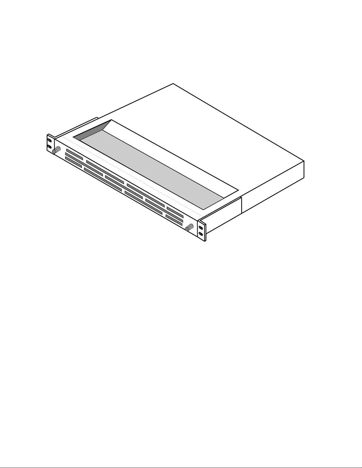
Six Rack Unit Frame (10.5 in. or 267 mm high)
Figure 1-5 illustrates a 6 RU MCF frame with the door closed. Figure 1-6
illustrates a fully optioned 6 RU frame with the front door removed. You
may remove the front door to simplify any module placement and to
connect the fiber cable. The door is hinged and opens from right to left. It
is secured closed by turning the crosshead lock screw clockwise until fully
secure. To remove the door, turn the screw counterclockwise, open the door
fully, and then lift it up and away from the frame.
MCF Installation and Service 1-5
Page 24

Section 1 — System Description and Specifications
CAUTION The frame door must be kept closed during operation to ensure proper air flow
and system cooling.
TP5144-06
Hinge
Figure 1-5. MCF 6 RU Frame
Door
R
JO
A
M
M
R
A
L
A
R
O
IN
M
M
R
A
L
A
Lock
Screw
Fiber-Optic
Cable
TP5139-02
Figure 1-6. Fully Optioned MCF 6 RU Frame (with door removed)
1-6 MCF Installation and Service
Page 25

System Description
A maximum configuration (ten module slots) consists of one Fiber module
and nine of the other modules. You can substitute one module of any of the
video/audio combination modules (such as Serial/Digital) for the two
Video and Audio modules. However, because there are only six time slots
available, you can use only six combination modules. Serial digital and
baseband analog video and audio signals can be mixed in the system as
long as the six time slots are not exceeded. Serial digital requires one or two
timeslots depending upon configuration.
Note Slot 19 in the 6 RU frame
be used for a Fiber module.
must
Table 1-1 shows what types of modules you can have in a maximum 6 RU
configuration. Except for a Repeater frame (which receives and transmits),
MCF frames are used for either transmitting or receiving. You cannot mix
input and output modules in the same frame.
Table 1-1. MCF 6 RU Frame Configuration
Requirements Transmitter Frame Repeater Frame Receiver Frame
One Required Fiber Transmitter Fiber Receiver Fiber Receiver
One Required Does Not Apply Fiber Transmitter Does Not Apply
From one up to nine
modules. Logical
types can be mixed
within frame.
Exceptions:
Repeater frame maximum is eight modules
because two slots are
being used by Fiber
modules. Combination modules maximum is six
a
Optional. Used only for monitoring purposes in this type of frame.
Video Input Module(s) Video Output Module
Audio Input Module(s) Audio Output Module
Serial Digital Input Module(s) Serial Digital Output Module
Combined Video/Audio Input
Module(s)
Video/Audio Input Module(s) Video/Audio Output Module(s)
Combined Video/Audio Output Module
a
a
a
Video Output Module(s)
Audio Output Module(s)
Serial Digital Output Module(s)
Combined Video/Audio Output
a
Module(s)
Two Rack Unit Frame (3.5 in. or 89 mm high)
Figure 1-7 illustrates a 2 RU MCF frame with the door closed. Figure 1-8
illustrates a 2 RU frame with the front door removed. You may remove the
front door to simplify any module placement and to connect the fiber cable.
The door panel is secured closed by turning the two crosshead lock screws
at the sides of the frame until fully locked. To remove the door panel, turn
both screws in the direction of the arrows, and then pull the door away
from the frame.
MCF Installation and Service 1-7
Page 26

Section 1 — System Description and Specifications
CAUTION The frame door must be kept closed during operation to ensure proper air flow
and system cooling.
G
ra
s
s
V
a
lle
y
L
O
C
K
Screw
5143-208
M
A
J
O
R
A
L
A
R
M
M
INO
R A
L
A
R
Door Panel
M
L
O
C
K
MCF
Series
Screw
Figure 1-7. MCF 2 RU Frame
AC POWER SUPPLY
POWER OK
DC POWER SUPPLY
POWER OK
VIDEO/
VIDEO/
MCF
AUDIO
AUDIO
FIBER
INPUT
INPUT
XMIT
CLIP QUIET
CLIP QUIET
MAJOR
ALARM
LASER
POWER
MODULE
TEMP
MINOR
ALARM
ONLINE
ONLINE
EQ
GAIN
EQ
GAIN
MONITOR
MONITOR
Figure 1-8. Fully Optioned MCF 2 RU Frame (with door removed)
A maximum configuration (three slots) is one Fiber module and up to two
of the other modules. You can substitute one module of any of the video/
audio combination modules (such as Combined Video/Audio) for the two
Video and Audio modules. Slot 12 in the 2 RU frame must be used for a
Fiber module.
5143-103
1-8 MCF Installation and Service
Page 27

System Description
Table 1-2 shows what types of modules you can have in a maximum 2 RU
configuration. Except for a Repeater frame (which receives and transmits),
MCF frames are used for either transmitting or receiving. You cannot mix
input and output modules in the same frame.
Table 1-2. MCF 2 RU Frame Configuration
Requirements Transmitter Frame Repeater Frame Receiver Frame
One Required Fiber Transmitter Fiber Receiver Fiber Receiver
One Required Does Not Apply Fiber Transmitter Does Not Apply
One or two modules. Logical
types can be mixed within frame
Exception:
Repeater frame maximum is one
module because two slots are
being used by Fiber modules.
a
Optional. Used only for monitoring purposes in this type of frame.
Video Input Module(s) Video Output Module
Audio Input Module(s) Audio Output Module
Serial Digital Input Module(s) Serial Digital Output Module
Combined Video/Audio Input
Module(s)
Video/Audio Input Module(s) Video/Audio Output Module(s)
Combined Video/Audio Output Module
a
a
a
Video Output Module(s)
Audio Output Module(s)
Serial Digital Output Module(s)
Combined Video/Audio Output
a
Module(s)
Fiber Modules
On the following pages, we discuss each of the frame components: Fiber
modules, Video modules, Audio modules, Serial Digital modules, Video/
Audio Diplexer modules, power supplies, and the backplane.
Fiber modules can be used as transmitters, receivers, or repeaters. As a
transmitter, the Fiber module transmits the MCF signal at the near end. As
a receiver, the Fiber module receives the MCF signal at the far end. A
repeater receives the MCF signal at one or more locations in the transmission link and then retransmits it again so it can be sent over longer distances. Refer to Section 1 of the MCF Operation Reference for more
information about the different operations.
The maximum optical loss budget of a current MCF system is 23 or 29 dB
when 0 dBm is launched. Fiber Transmitter modules operate in 1300 or
1550 nm wavelengths. Each Fiber module comes with FC/PC, SC, or ST
connectors. Except for the fiber-optic connector on the front of the board,
communication with the system passes through the backplane. The time
slot interchange function found on these modules allows time slot manipulation for greater flexibility.
It is also possible to drop signals for monitoring and distribution from
either the Repeater or Receiver MCF frame.
See Table 1-7 on page 19 for a list of functional specifications.
MCF Installation and Service 1-9
Page 28

Section 1 — System Description and Specifications
Combined Video/Audio Modules
The Video/Audio Input and Output modules consolidate the functions of
two MCF modules—they are the functional equivalent of the separate
Video and Audio Input and Output modules. Using these modules, up to
six video and 24 audio channels can be accommodated in the MCF system’s
6 RU frame. In the 2 RU frame, up to two video and eight audio channels
can be accommodated. MCF bus data for each module occupies one video
and one audio time slot.
The following descriptions for the separate Video and Audio Input and
Output modules are functionally the same and have more details. Refer to
them if you need more information. Also see Table 1-7 on page 1-19 for a list
of functional specifications.
Video Modules Input and Output
The MCF System bandwidth allows up to six video channels (one per
module) to be transported over a single fiber. Video is digitized and halfband filtered with a signal-to-noise ratio of >67 dB. Video is sampled at
31.054 MHz, which yields a flat video passband maximum of approximately 6.89 MHz.
MCF is format independent—NTSC, PAL, and other video formats can be
passed through these modules. Other video parameters are per EIA/TIA250-C Short Haul. Video and audio travel in separate time slots and are
switched separately.
Audio Modules Input and Output
The MCF System bandwidth allows up to twenty-four analog baseband
audio channels to be transported over a single fiber. Each audio module
provides two stereo audio pairs, or four channels.
Audio channels are digitized at 18-bits. Current interfaces are discrete
analog. Signal-to-noise ratio is approximately 90 dB. Other audio parameters are per EIA/TIA-250-C Short Haul, and ANSI T1.505.
Serial Digital Modules
The Serial Digital Input and Serial Digital Output modules are designed to
provide component serial video at 270 MHz (D1) or NTSC composite serial
video at 143 MHz (D2) and two AES/EBU serial audio interfaces to the
MCF transmission system. The AES/EBU audio may be embedded in the
serial digital video signal, or carried separately.
1-10 MCF Installation and Service
Page 29

Audio uses two asynchronous stereo pairs. The audio input data clock is 48
kHz (± 400 ppm) for both audio inputs. Each channel can be independently
enabled or disabled by software commands through the Fiber module.
Component (270 MHz, D1) serial video has a higher data rate that requires
more bandwidth, so two time slots are required. The audio that goes along
with the component video is not split between two time slots but is
assigned to the primary time slot. NTSC composite (143 MHz, D2) serial
video requires only one time slot.
See Table 1-8 on page 21 for a list of the video and audio performance specifications.
Video/Audio Diplexer Modules Input and Output
The Video/Audio Diplexer module occupies one MCF video time slot. The
video carried in this module is baseband analog (see the previously
described Video modules description for details). However, the audio is
different. The Diplexer uses an audio-follow-video scheme to add subcarriers with video in a common time slot. This analog audio is not meant to
replace digital audio—but to provide more channels. The audio input stage
accommodates 600 Ohm balanced +18 dBm peak level signals.
System Description
Backplanes
Backplane for the 6 RU Frame
Audio subcarriers of 5.8 and 6.4 MHz are diplexed onto traditional TV1
video signals. The center frequencies of the FM subcarriers are fixed at 5.8
and 6.4 MHz using slow feedback phase locked loops (PLLs). The peak-topeak deviation is 370 kHz at maximum modulation. The subcarriers are
summed with the filtered video at a relative level of –20 dBV (100 mV peakto-peak) per carrier.
See Table 1-7 on page 1-19 for a list of functional specifications and see
Table 1-9 on page 22 for a list of the audio performance specifications.
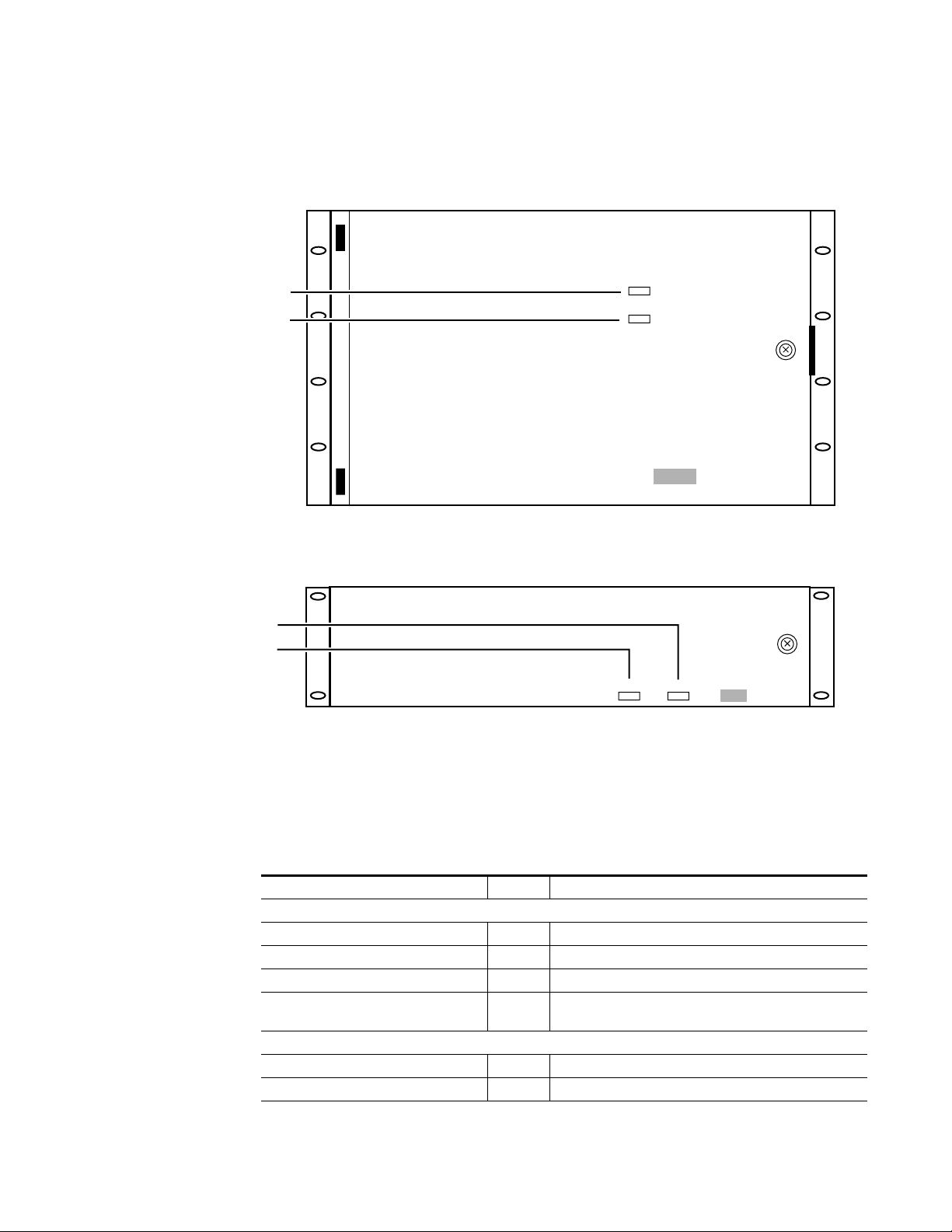
The following text describes the attributes of the system in the 6 RU frame
and 2 RU frame configurations.
Except for the fiber-optic cable connector and monitor connectors on the
Video Input/Output modules, connections to the MCF 6 RU frame are
made through the backplane. In addition to the communication connections, the backplane connector groupings for the 12 slots. Two are dedicated for power supplies and one for the Fiber module (either the Receiver
or Transmitter). The remaining nine slots are used for combinations of
video and audio type modules. Remember, you cannot mix input and
output modules in the same frame.
MCF Installation and Service 1-11
Page 30

Section 1 — System Description and Specifications
Each module connects to the backplane through two connectors. One connector is dedicated to analog interfaces. The second connector supports the
internal communications bus. All video and audio type modules connect to
this bus. On the rear of the backplane, each non-Fiber module has three
BNC connections (two video inputs for loop-through, and one video I/O)
and a screw strip connector for the two stereo audio pairs. Serial/Digital
modules use the loop-through connectors separately (loop-through disabled) for I/O monitoring. Figure 1-9 illustrates the 6 RU backplane.
Video/Audio
Connectors
GRASS VALLEY GROUP, INC.
MODEL: MCF SERIES
DATE OF
MFG
MADE IN U.S.A.
Communication
Connectors
Power
Supply
RATED VOLTAGE: 100-120VAC~/200-240VAC~/ 48VDC
RATED CURRENT: 6 A MAX / 3 A MAX / 12 A MAX
FREQUENCY: 50-60Hz 50-60Hz
Connectors
48VDC
GND
J1
S1
110 220
J3
120/240 VAC
—+
WARNING
IF EQUIPPED WITH REDUNDANT POWER
THIS UNIT HAS TWO POWER CORDS.
TO REDUCE THE RISK OF ELECTRIC
SHOCK, DISCONNECT BOTH POWER
CORDS BEFORE SERVICING.
Zur Trennung vom Netz
§
beide Netzanschlu
Leitungen entfernen.
Fan Power
Connector
Figure 1-9. Backplane for the 6 RU Frame
Backplane for the 2 RU Frame
Except for the fiber-optic cable connector and monitor connectors on the
Combined Video/Audio and standard video modules, connections to the
MCF 2 RU frame are made through the backplane. Two slots are dedicated
for power supplies and one slot is dedicated for the Fiber module (either
Receiver or Transmitter). The remaining two slots are used for combinations of video and audio type modules. Remember, you cannot mix input
and output modules in the same frame.
WARNING
VERIFY VOLTAGE SETTING
BEFORE APPLYING POWER
Vor Anschlu§ on das Netz
Aufstellanitung beachten!
-
120/240 VAC
48VDC
GND
J2
S2
110 220
J4
—+
ETL LISTED
E
L
TELEPHONE
T
EQUIPMENT
Conforms to ULSTD 1459
ETL TESTING LABORATORIES, INC.
CORTLAND, NEW YORK, 13045
THIS DEVICE COMPLIES WITH PART
15 OF THE FCC RULES OPERATION
SUBJECT TO THE FOLLOWING TWO
CONDITIONS: (1) THIS DEVICE MAY
NOT CAUSE HARMFUL INTERFERENCE
(2) THIS DEVICE MUST ACCEPT ANY
INTERFERENCE RECEIVED INCLUDING
INTERFERENCE THAT MAY CAUSE
UNDESIRED OPERATIONS.
CAUTION:
This unit has more than one power source.
Disconnecting power cords
may not de-energize unit.
ATTENTION:
Ca produit a plus qu’une Source de pouvior
electrique. Debranchement n’ assure pas
de-energisation de I’ equipement.
0
SLOT
USE
FIBER1AUD/VID
RS485/
RS232
ADMIN.
PORT
J01
POWER
FAN
J5
AUDIO/
DATA
ALARM
J02
B
CC
D
J03
EXP
VIDEO
I/O
IN
VIDEO
I/O
RS232
CRAFT
PORT
J04
AUD/VID AUD/VID
-
+
-
+
-
+
-
+
IN 4
J32
J33
54
AUD/VID
AUDIO/
DATA
GND
-
AA
+
GND
-
B
+
GND
-
+
GND
-
D
+
J41
J51
IN 5
IN 6
J42
J52
J53
J43
AUD/VIDAUD/VID
AUD/VID DATA
AUDIO/AUDIO/AUDIO/AUDIO/
AUDIO/
DATA
B
CC
D
J61
IN 7
J62
J63
AUDIO/
DATA DATA DATA DATA
DATA
GND
-
AA
+
GND
-
B
+
GND
-
C
+
GND
-
D
+
J71
J81
IN 8
J72
J82
J83 J93
J73
3
2
AUD/VID
AUD/VID
AUDIO/
DATA
GND
-
+
GND
-
+
GND
-
+
GND
-
+
J11
IN 1
J12
I/O 1 I/O 2 I/O 3 I/O 4 I/O 5 I/O 6 I/O 7 I/O 8 I/O 9
J13
GND
A
GND
B
GND
GND
D
J21
J31
IN 2
IN 3
J22
J23
7
6
5158-99
98
SLOT
USE
GND
-
+
GND
-
+
GND
-
+
GND
-
+
J91
VIDEO
IN 9
IN
J92
VIDEO
I/O
Each module connects to the backplane through two connectors. One connector is dedicated to analog interfaces. The second backplane connector
supports the internal communications bus. All video and audio type
modules connect to this bus. On the rear of the backplane, each non-Fiber
type module has three video BNC connections (two for loop-through [J2-J3
or J5-J6] and one for I/O [J1 or J4]) and a screw strip connector for the two
1-12 MCF Installation and Service
Page 31

System Description
stereo audio pairs. Serial/Digital module use the loop-through connections
(J2-J3 or J5-J6) separately (loop-through disabled) for I/O monitoring.
Figure 1-10 illustrates the 2 RU backplane.
Video/Audio
Connectors
J2 J3
J1
J10
J4
J5
J6
J11
J8
J9
J7
J13
J12
Communication
Connectors
Figure 1-10. Backplane for the 2 RU Frame
Fan Assembly (6 RU only)
The fan assembly consists of three (3) muffin fans in a housing which is
mounted immediately above the frame in the equipment rack. A removable
air filter is in the front panel. Warm air is drawn up through the frame and
Alarm
Connector
E
T
ETL TESTING LABORATORIES, INC.
CORTLAND, NEW YORK, 13045
THIS DEVICE COMPLIES WITH PART
15 OF THE FCC RULES OPERATION
SUBJECT TO THE FOLLOWING TWO
CONDITIONS: (1) THIS DEVICE MAY
NOT CAUSE HARMFUL INTERFERENCE
(2) THIS DEVICE MUST ACCEPT ANY
INTERFERENCE RECEIVED INCLUDING
INTERFERENCE THAT MAY CAUSE
UNDESIRED OPERATIONS.
CAUTION:
This unit has more than one power source.
Disconnecting power cords
may not de-energize unit.
ATTENTION:
Ca produit a plus qu'une Source de pouvior
electrique. Debranchement n' assure pas
de-energisation de I' equipement.
L
TELEPHONE
EQUIPMENT
Conforms to ULSTD 1459
ETL LISTED
Exhaust
Fan
Power Supply
Connectors
+
GND
–
+
GND
–
5158-98
MCF Installation and Service 1-13
Page 32
Section 1 — System Description and Specifications
exhausted out the back of the equipment rack. Power to the fan assembly
is supplied from a connector on the backplane of the frame. Figure 1-11
illustrates the fan assembly.
5144-02
Figure 1-11. MCF Fan Assembly
Deflector Assembly (6 RU only)
The deflector assembly consists of the same housing and air filter as the fan
assembly, except without fans. It is mounted immediately below the frame.
Ambient air is drawn in through a filter and deflected up through the
frame.
1-14 MCF Installation and Service
Page 33

Physical Specifications
The physical specifications of each component of the MCF are listed in
Table 1-3.
Table 1-3. MCF System Physical Specification
Component Height Width Depth Weight
2 RU Frame
6 RU Frame
Fan Assembly
Deflector Assembly
a
Fully optioned
3.5 in.
(88.9 mm)
10.5 in.
(267 mm)
1.75 in.
(44.4 mm)
1.75 in.
(44.4 mm)
17.25 in
(438 mm)
17.25 in
(438 mm)
17.25 in.
(438 mm)
17.25 in.
(438 mm)
10.5 in.
(267 mm)
10.5 in.
(267 mm)
10.5 in.
(267 mm)
10.5 in.
(267 mm)
Physical Specifications
a
20.0 lbs
(9.1 kg)
35.0 lbs
(15.9 kg)
8.5 lbs
(3.9 kg)
7.5 lbs
(3.4 kg)
Rack
Units
2
6
1
1
Power Specifications
Source power to the frame enters through connectors on the rear of the
backplane. Power for frame components is from one or two AC power supplies, one or two DC power supplies, or one of each, depending on your
facility requirements. Table 1-4 lists the power supply specifications.
Table 1-4. MCF Power Specifications
Parameter Value
Primary Power (AC, DC, or mixed AC/DC)
AC
DC
Power Capability
6 RU frame
2 RU frame
Redundancy (hot pluggable) Each AC or DC supply will support entire load
90–132 or 180–264 VAC, 47–63 Hz
–42 to –56.7 VDC
15W per module (nominal), 250W total
15W per module (nominal), 45W total
MCF Installation and Service 1-15
Page 34

Section 1 — System Description and Specifications
Regulatory Compliance
The MCF System meets the following regulatory requirements:
■ UL 1459
■ UL 1950
■ CSA 22.2 #950
■ EN 60950
■ NEBS TR-NWT-000063
■ FCC 15A
■ EN 55022 (CISPR–22A)
■ EN 50082-1 (IEC 801-2, -3, -4)
■ GR-1089 (sec. 2,3,4,7,9)
■ GR-63-CORE (sec. 2,3,4)
Environmental Criteria
The MCF System meets the environmental criteria listed in
Table 1-5.
Table 1-5. MCF System Environmental Criteria
Operating 0° to 50° C (per NEBS) 0–95% non-condensing
Non-Operating (Storage) –10° to 70° C 0–95% non-condensing
Cooling (6 RU) Forced air, 1 RU Active Vent, 1 RU Passive Filter
Alarm Indicators
The MCF system is equipped with both visual alarms and system (monitor)
indications. These alarms and messages are designated as Minor (possible
deterioration of system performance) and Major (loss of system operation).
Temperature Humidity
1-16 MCF Installation and Service
Page 35
Major Alarm
Minor Alarm
Alarm Indicators
Note that you can see the Minor and Major alarm indicators through the
MCF frame door. For the 6 RU frame, refer to Figure 1-12. For the 2 RU
frame, refer to Figure 1-13.
Grass Valley
MAJOR
ALARM
MINOR
ALARM
MCF Series
Minor Alarm
Major Alarm
Figure 1-12. Alarm Indicators for the 6 RU Frame
Grass Valley
Major Alarm
Minor Alarm
MCF Series
Figure 1-13. Alarm Indicators for the 2 RU Frame
Table 1-6 lists the source of an alarm, the visual alarm indicator, and the
system Minor and Major Alarm designations.
Table 1-6. MCF System Alarm Indications
Indicator Status System Indication (Minor/Major)
Fiber Transmitter
Major Alarm (red) On RF drive not present or invalid
Laser Power (red) On Laser Power out of limits (minor)
Module Temp (red) On Module temp out of limits (minor)
Minor Alarm (amber) On
Fiber Receiver
Major Alarm (red) On Optical input not present
Module Temp (red) On Module temp out of limits (minor)
Power supply failed or not present and out of current or temperature limits
MCF Installation and Service 1-17
Page 36

Section 1 — System Description and Specifications
Table 1-6. MCF System Alarm Indications - (continued)
Indicator Status System Indication (Minor/Major)
Input Pwr (green) Flash Optical input power too high (minor)
Input Pwr (red) On Optical input power too low (major)
Input Pwr (amber) On Bit error rate has degraded (minor)
Minor Alarm (amber) On
Combined Video/Audio Modules Input/Output
Clip (amber) On Module overdriven
Quiet (green) On No Input/Output
LOS (amber) (Video/Audio Output module
only)
Online (green) Off Module muted (offline) or inoperative
Video Modules Input/Output
Clip (amber) On Module overdriven
Quiet (green) On No Input/Output
LOS (amber) Video (Output module only) On Data signals not present
Online (green) Off Module muted (offline) or inoperative
Audio Modules Input/Output
Clip, 4 each (amber) On Channel(s) overdriven
Quiet, 4 each (green) On Input/Output to channel(s) –50 dB from full scale
LOS Audio (amber, Output module only) On Audio carrier not present
Online (green) Off Module muted (offline) or inoperative
Serial Digital Modules Input/Output
Video Online (green) Off Time slots not assigned or muted
270 MB/S 2 Timeslots (green) Off
143 MB/S 1 Timeslots (green) Off
Video Present (green, Input module only) Off Input video not present
Video Loss of Power (red, Output module
only)
1/2 or 3/4 Audio Channel (green) Off Audio not present or time slots not assigned or muted
1/2 or 3/4 Audio Present (green, Input mod-
ule only)
Audio Loss of Power
(green, Output module only)
Video/Audio Diplexer Modules Input/Output
Video Clip (amber) On Module overdriven
Video Quiet (green) On No input/output
Audio Clip (amber) On Channel(s) overdriven above +18 dBm
Audio Quiet A or B (green) On No input/output to channel(s)
Video Online (green) Off Module muted or inoperative
Power supply failed or not ‘present and out of current or temperature limits
On Video or Audio signal not present
Component video not being used, 270/143 jumper set incorrectly, or input video not present
NTSC composite video not being used, 270/143 jumper set
incorrectly, or input video not present
On
Off
On No data on the bus, or Input module unplugged or muted
Input module muted or unplugged, input video not present. If
just a flash, auto reset by the system
Muted time slots on Input module or invalid ASE/EBU audio
input stream
1-18 MCF Installation and Service
Page 37

Table 1-6. MCF System Alarm Indications - (continued)
Indicator Status System Indication (Minor/Major)
A/B Online (green) Off Subcarriers muted or inoperative
DPLX (green, Output module only) On Subcarriers not being separated from video
Video/Audio LOS (amber, Output module
only)
Power Supplies
AC OK/DC OK (green) Off
Functional Specifications
Table 1-7 lists the MCF system functional specifications. These specifications meet or exceed EIA/TIA-RS-250-C Short Haul and ANSI T1.505
requirements. Table 1-8 lists only the serial digital functional specifications
for the MCF Serial/Digital module that are different from the general specifications listed for the MCF system. Table 1-9 lists only the audio functional specifications for the MCF Video/Audio Diplexer module that are
different from the general audio functional specifications listed for the
MCF system.
Functional Specifications
On Invalid data stream or subcarriers not present
Power supply failed (minor)
Power supply present and out of
limits (minor)
Table 1-7. MCF System Functional Specifications
Parameter Value
Optical Characteristics
Launch Power: 9 µm fiber core (typical)
1310 or 1550 nm, Laser ±5 nm 0 dBm
-10
Receive power for 1x10
Optical Connector Options FC/PC, SC, or ST (9/125 µm cable)
Recommended Maximum Optical
Back Reflection
Receiver Operation and Survivability
Bit Error Rate < 1x10
High Speed Bus Architecture Characteristics
Transmission Rate 1.25 GBaud
Data Rate 1.0 Gb/sec
Video Six 10-bit time slots
Audio Twelve 20-bit audio pairs (AES/EBU)
Video In/Out, Video/Audio In/Out, and Diplexer Characteristics
Video Sample Rate 31.054 MHz
Quantization 10-bit linear, digitally half-band filtered
Effective Number of Bits (ENOB) 9.25 bits
Cable Equalization Up to 300 meters of selected coaxial cable types
1310/1550nm –23 dBm or –29 dBm
Less than –30 dB
Fiber Receiver meets specifications with optical inputs between
–23dBm and –10dBm
-10
MCF Installation and Service 1-19
Page 38

Section 1 — System Description and Specifications
Table 1-7. MCF System Functional Specifications - (continued)
Parameter Value
Frequency Response Meets or exceeds EIA/TIA-RS-250-C Short Haul requirement
Chroma to Luma Gain Inequality < ±2 IRE
Chroma to Luma Delay Inequality < ±15 nanoseconds
Field Time Waveform Distortion < 2 IRE
Line Time Waveform Distortion < 0.5 IRE
Short Time Waveform Distortion < 2%
Bounce < 8 IRE, 3 second settling time
Line-by-Line DC Offset < 2 IRE
Insertion Gain 0 dB
Insertion Gain Variation ±0.15 dB
Luminance Nonlinearity < 4%
Differential Gain < 1.5%
Differential Phase < 0.7°
Chrominance to Luminance
Intermodulation
Chrominance Nonlinear Gain < 1 IRE
Chrominance Nonlinear Phase < 1°
Dynamic Variation of Synchronizing Signal < 1.2 IRE
Transient Sync Signal Nonlinearity < 1 IRE
Video Signal/Noise Ratio Better than 67 dB
Signal to Low Frequency Noise Ratio Better than 55 dB
Signal to Periodic Noise Ratio Better than 67 dB
Return Loss 30 dB, 0–4.2 MHz
Audio Input/Output and Video/Audio Input /Output Module Characteristics
Audio Sample Rate 48 kHz
Quantization
Input Impedance 150Ω, 600Ω, >10 KΩ, balanced
Frequency Response
Maximum Audio Level (full code) Switch selectable in 4 dB steps between +24 dBm and +8 dBm
Total Harmonic Distortion + Noise < 0.05%, 400 Hz at 24 dBm
Intemodulation Distortion < 0.05 percent per T1.505
Signal-to-Idle Channel Noise Ratio ≥ 88 dB, reference 1 kHz at full code
Channel-to-Channel Crosstalk ≤ –84 dB at 1 kHz
Interchannel Crosstalk ≤ –84 dB at 1 kHz
Gain Difference Between Stereo A and B Channels 0.25 dB, 20 Hz–20 kHz
Phase Difference Between Stereo A and B Channels 2°, 20 Hz–20 kHz
Audio-to-Video Transmission Time Differential < 10 ms maximum lead or lag
Common Mode Rejection Ratio > 60 dB @ 60 Hz, > 50 dB @ 20 Hz to 20 kHz
peak-to-peak
peak-to-peak
< 1 IRE
18-bit linear, digitally filtered from 1-bit delta sigma at 64 times
over-sampling
±0.20 dB, 20 Hz–20 kHz, reference 1 kHz
@ –15 dB from full code (no weighting)
1-20 MCF Installation and Service
Page 39

Functional Specifications
Table 1-7. MCF System Functional Specifications - (continued)
Parameter Value
Data Performance
Maximum Slew Rate 30 V/µs
-9
Bit Error Rate < 10
Baud Rate
Power Consumption
Input Module < 9 watts
Output Module < 12.5 watts
Table 1-8. Serial/Digital Functional Specifications
Parameter Value
Video Performance
Input Signal Description
Cable Equalization
Cable Output Drive > 300m of 8281 into TEK 601i
Input Signal Data Type
Number of Outputs
Impedance 75 Ohms
Return Loss > 15 dB (10 MHz to 270 MHz)
Rise and Fall Times (20% to 80%)
Rise and Fall Differential < 0.5 nanoseconds
Connector Type 75 Ohm BNC
Signal Amplitude 800 mV ±10% when terminated into 75 Ohms
DC Offset < ± 0.5V
Video Output
Serial Component Jitter
errors per second
19.2 kB/sec, limited by mechanical interface requirement of EIA232D
Conforms to SMPTE 259M (except cable EQ). Interface for
10-bit 4:2:2 component and 4 fsc NTSC composite digital
signals
Using pathological signals from GVG M9900 module. Automatic to < 250 meters for D2 and < 200 meters for D1 of
Belden 8281 or equivalent type coax cable
8-/10-bit serial video. Note: The Input module has one additional front panel monitor output BNC to monitor the presence of an input signal
One. Note: The Output module has two additional monitor
outputs. One is at the front panel and the other at the MCF
frame backplane
0.4 nanoseconds to 1.5 nanoseconds when terminated into
75 Ohms
< 740 picoseconds peak-to-peak
Serial Composite Jitter
Audio Performance
Digital Inputs (2) and Outputs (2) Differential, biphase-mark encoded AES3-1992
Signal Amplitude 200 mv to 7V ± 10% when driving 110 Ohm differential load
DC Offset < ± 0.5V
< 1.1 nanoseconds peak-to-peak
MCF Installation and Service 1-21
Page 40

Section 1 — System Description and Specifications
Table 1-8. Serial/Digital Functional Specifications - (continued)
Parameter Value
Rise and Fall Times (20% to 80%)
Connector Type Phoenix four 12 station block
Impedance 110 Ohms
Input Common Mode Voltage 7 VDC 20 kHz
Audio Output Jitter < 20 nanoseconds peak-to-peak
Table 1-9. Video/Audio Diplexer Audio Functional Specifications
Parameter Value
Frequency Response Meets or exceeds template in EIA/TI RS-250-C
Input/Output Level
Total Harmonic Distortion < 0.25%, 400 Hz at +18 dBm
Signal-to-Noise Ratio > 70 dB, reference 400 Hz at full deviation
Gain Difference between Stereo A and B Channels
Phase Difference between Stereo A and B Channels
Interchannel/Stereo Channel-to-Channel Crosstalk < –56 dB, 50 Hz to 15kHz
Subcarrier Injection Level 100 mV peak-to-peak (–20 dBV) per carrier (nominal)
Availability of the Audio Signal 99.99%
Audio-to-Video Transmission Time Differential 25 ms lead to 40 ms lag
Audio Pre-emphasis/De-emphasis 75 µsec
Common Mode Rejection Ratio
Input DC Common Mode Voltage ±25 VDC
FM Deviation 185 kHz peak, 400 Hz test tone at +18 dBm
Input Impedance 150, 500, >30K Ohms differential (DIP switch select)
Audio Inputs Differential Analog (DC to 15 kHz)
Audio Outputs Differential Analog (DC to 15 kHz)
Maximum Output Level +18 dBm
Output Impedance 15 Ohms differential
5 nanoseconds to 130 nanoseconds when terminated into
110 Ohm differential load
+ 18 dBm nominal, five discrete 3 dBm gain steps plus continuous ±6 dBm adjust
50–100 Hz 1.0 dB
100–7500 Hz 0.5 dB
7.5–15 kHz 1.0 dB
50–100 Hz < 10°
100–7500 Hz < 3°
7.5–15 kHz < 10°
> 60 dB, 60 Hz
> 50 dB, 20 Hz to 10 kHz
1-22 MCF Installation and Service
Page 41

Terms Used
Terms Used
The following is a list of terms used in this manual.
Communication Ports
The Craft and Administration serial data ports (RS-232, RS-485) on the back
of the MCF system that allow you to communicate with the system. The
ports are also referred to as control data ports.
Cross-Connect
A connection between any I/O board and a time slot in the fiber signal.
Dark Fiber
Dedicated optical fiber leased from a common carrier.
Diplex Operation
The simultaneous transmission or reception of two messages on a single
carrier.
Drop Monitor
The ability to drop off a signal from the Repeater frame for monitoring purposes. This can be used for troubleshooting.
Earth Ground
A ground connection from the equipment frame to a metal rod driven into
the earth.
Error Messages
Messages generated by the control system indicating fault conditions. Messages are displayed on a monitor connected to the Craft or Admin port. See
the Protocol and User’s manuals for more information.
FC/PC Connector
A low-loss fiber connector option provided on the front of the Fiber
Receiver and Transmitter modules.
FIFO
First In First Out. Holds video data samples. The FIFO also separates the
system clock from the video sample clock.
LOS
Loss of Signal. When there is no valid signal present in the selected time
slot of an output board, or at the input of the Fiber Transmitter module.
MCF Installation and Service 1-23
Page 42

Section 1 — System Description and Specifications
Loss Budget
The amount of anticipated signal loss over a given fiber optic path,
including attenuation, connector loss, splice loss, and other losses.
One-to-Many Connection/Transmission
One time slot on the fiber bus is associated with multiple Output boards.
Available in the Receiver frame only.
One-to-One Connection/Transmission
Only one video and/or audio input board is associated with the same time
slot on the fiber bus. Available in the Transmitter frame or Receiver frame.
Optical Receiver Sensitivity
The minimum level of optical power required at the receiver input to guarantee satisfactory operation.
Optical Receive Power
The level of optical power arriving at the receiver as measured with an
optical power meter.
Ramp Signal
Test signal that graduates from low DC level to high DC level; used to test
signal path.
SC Connector
A low-loss fiber connector option provided on the front of the Fiber
Receiver and Transmitter modules.
ST Connector
A low-loss fiber connector option provided on the front of the Fiber
Receiver and Transmitter modules.
STUFF
“Place Holder Data” inserted to correct for uncertainty in real data time of
arrival.
Time-Division Multiplexing
A method of multiplexing in which a common transmission path is shared
by a number of channels on a cyclical basis. This is accomplished by
enabling each channel to use the path exclusively for a short time slot.
1-24 MCF Installation and Service
Page 43

Terms Used
Time Slot
Any cyclic time interval which can be recognized and uniquely defined.
TV1 Diplexed Signal
Industry standard for transmission of Audio subcarriers above Video baseband.
Unidirectional Signal
A signal that only goes in one direction. A one-way connection or transmission.
Video Cable Equalization
Use of hybrid equalizers to correct the high frequency loss associated with
signals transmitted over long lengths of coaxial cable.
MCF Installation and Service 1-25
Page 44

Section 1 — System Description and Specifications
1-26 MCF Installation and Service
Page 45

Installation
Installation Overview
The following topics are covered in this section:
■ Pre-Installation Planning
■ Unpacking and Inspecting the Equipment
■ Installing the MCF System
■ Six Rack Unit Frame (6 RU)
■ Two Rack Unit Frame (2 RU)
■ Making Connections
■ Video
Section 2
■ Audio
■ Fiber-Optic
■ Making Jumper and DIP Switch Selections and Required Adjustments
for Each Module
■ NRZ/NRZI Modes and Compatibility
■ Installing Modules in the Frame
■ Turning Power On
■ Operational Checkout
Note MCF systems are shipped with the modules already installed in the MCF
frames.
Pre-Installation Planning
Some preplanning is required before installing your MCF system. The following paragraphs describe specific items you need to address.
MCF Installation and Service 2-1
Page 46

Section 2 — Installation
Calculating Optical Fiber Path Loss Budget
Before installing your equipment it is important to calculate the optical loss
budget, which determines the amount of optical energy available at the
MCF Receiver unit. If the energy is too low, the noise floor rises and causes
excessive bit error rates. If the energy is too high, the Receiver’s optical
detector will be overdriven and cause excessive bit error rates.
To achieve specified performance in your current MCF system, the optical
power arriving at the receiver must be greater than –23 dBm (or -29 dBm
on recently-produced receiver boards) and less than –10 dBm (that is,
between –10 dBM and –23 dBm), as measured with an optical power meter.
The received power equals the difference between fiber path losses in your
facility and the output power transmitted into the fiber.
Output Power Transmitted = + 0.0 dB
Fiber Path Loss = –20.0 dB
Receive Power = –20.0 dB
If the received power exceeds –10 dBm (typical on very short fiber paths),
a fixed value optical attenuator can be inserted into the fiber path. To calculate your system’s total optical fiber path loss budget, see the following
example.
The total fiber path loss budget possible with the MCF system is 23 dB (or
29 with recent-production receivers) calculated according to the following
formula:
Device Loss Budget Allowance
9 µm Singlemode (1300nm) Cable 0.5 dB per kilometer
FC/PC Singlemode Connector 1.0 db per connector
Singlemode Splice 0.5 dB per splice
Note Manufacturer’s specified connector and splice losses are typically less than
those shown here. These losses are intended for use in Loss Budget calculations and, therefore, include allowance for degradation.
This example illustrates a fiber path loss budget calculation:
25 km single mode fiber @ 0.5 dB per kilometer = +12.5 dB
Four FC/PC connectors @ 1 dB per connector = + 4.0 dB
Ten splices @ 0.5 dB per splice = +
Total loss budget = +21.5 dB
This loss budget is within the range of the MCF system (between 0 dBm and
–23 (or -29) dBm).
For output power of the optical transmitter, refer to the specification table
found in Section 1 of this manual.
5.0 dB
2-2 MCF Installation and Service
Page 47

Space Planning
The MCF system installs in a standard 19-inch equipment rack where a
rack unit (RU) equals 1.75 inches (44.5 mm). The large MCF frame occupies
6 RUs and the required fan and deflector assemblies occupy 1 RU each for
a total of 8 RUs. (See the following subsection, “Installation of the MCF
system in the Equipment Rack,” for additional information.) The small
MCF frame occupies 2 RU. The 2 RU frame exhaust fan is inside the frame.
No additional fan or deflector assemblies are required, so the overall frame
height is 2 RUs.
Power Requirements
For DC operation, a –48 volt supply is required. For AC operation, nominal
line voltage of 120 or 240 volts, 50–60Hz is required. The 6 RU frame AC
operating voltage is selectable (110/220 VAC) via a switch at the rear of the
frame. The 2 RU frame is self-selecting. (See the following “Power Connection” subsection for additional information.)
Pre-Installation Planning
Heat Considerations
The MCF system operates in an ambient temperature range of 0° to 50° C.
Humidity
This equipment operates within an ambient non-condensing humidity
range of 0% to 95%.
MCF Installation and Service 2-3
Page 48

Section 2 — Installation
Unpacking the Equipment
Follow the steps given here and on the following page as you unpack the
Tektronix equipment.
Receiving Inspection
Inspect all shipping containers for any signs of damage. If any damage is
found, notify the shipping company immediately.
Unpacking
Follow the safety precautions found in Steps 1 through 4 when unpacking
the Tektronix equipment.
1. Place the shipping containers on a flat, level surface with enough room
to move the containers around as needed.
2. Locate the shipping container with the small plastic pouch and remove
the Packing List.
CAUTION When handling the Fiber Transmitter and Fiber Receiver, avoid unnecessary
handling of the fiber pigtail and connector which can be broken or damaged by
improper handling. Damage due to mishandling is not covered by warranty.
3. Open the shipping containers, carefully remove the contents, and place
the contents on a flat, level surface.
4. Compare the contents in each shipping container with the packing list
to ensure there are no missing items. Make notes of any discrepancies.
For a single 6 RU system, each terminus should have a
■ Frame
■ Fan Assembly
■ Deflector Assembly (identical to the fan assembly but lighter as it does
not have the fans)
For multiple 6 RU frame systems mounted in a telco-rack, separate
deflector assemblies are not required.
The 2 RU frame system is entirely self contained. No fan or deflector assemblies are included.
If there are any discrepancies between the packing list and items received,
contact Tektronix Customer Service.
2-4 MCF Installation and Service
Page 49

Installation of a 6 RU Frame in the Equipment Rack
Equipment Inspection
Inspect all equipment for any visible damage. Items which should specifically be checked are
■ Connectors for bent or broken pins
■ Cables for crimped or broken wires
■ Glass fibers for breaks and kinks
■ Equipment chassis for any visible damage
If any damage is found, contact Tektronix Customer Service.
Note If an item is damaged, DO NOT make any power or signal connections unless
otherwise advised by Tektronix Customer Service.
Test Equipment and Tools Required
No specific test equipment required for the initial installation and setup of
your MCF system. A flat-blade and cross-head screwdriver are the tools
required to complete the installation.
Installation of a 6 RU Frame in the Equipment Rack
The 6 RU frame installs in a 19-inch (483 mm) equipment rack. A wider 23inch (584 mm) rack can be used with an optional 23-inch mounting bracket
kit (part number MCF-BRK-236). Figure 2-1 illustrates installation of a
MCF Installation and Service 2-5
Page 50
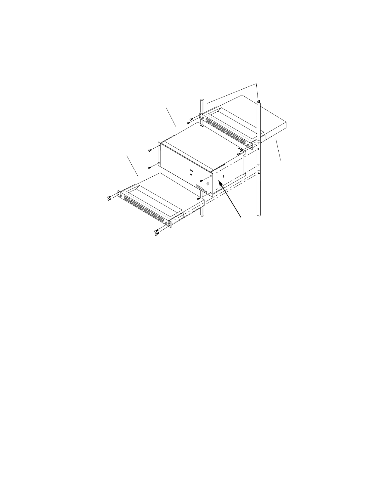
Section 2 — Installation
basic system and Figure 2-2 is an example of a multiple frame system. Four
bolts and the appropriate screwdriver are needed for installation of each
component.
Equipment Rack
MCF Frame
Deflector
Assembly
Figure 2-1. Installation in the 19-Inch Equipment Rack for the 6 RU Frame
Installing a 6 RU Frame
Grass Valley
5144-01
M
A
J
A
O
L
R
A
R
M
M
I
N
A
O
L
R
A
R
M
Fan
Assembly
Mounting Brackets
To install the 6 RU frame in the 19-inch equipment rack, see Figure 2-1 and
perform the following:
1. Position the frame in the equipment rack at the desired height and
secure it to the equipment rack with two bolts on each side.
2. Position the fan assembly immediately above the frame and secure it to
the equipment rack with two bolts on each side.
3. Position the deflector assembly immediately below the frame and
secure it to the equipment rack with two bolts on each side.
Note For installation into a 23-inch rack, fan and deflector assemblies mounting
brackets may be reversed.
The large MCF system requires eight contiguous rack units in the equipment rack: 6 RUs for the frame and 1 RU each for the fan and deflector
assemblies.
2-6 MCF Installation and Service
Page 51

Installing Multiple 6 RU Frames
To install multiple 6 RU frames in the 19-inch equipment rack, see
Figure 2-2 and ensure the following items:
■ 6 RUs are available for each frame
■ 1 RU is available for each fan assembly
■ 1 RU is available for the deflector assembly
■ In a stack of frames and fan assemblies, the deflector assembly is
installed at the bottom of the stack
■ A fan assembly fits above each frame
For example, the multiple frame example shown in Figure 2-2 would
require 15 contiguous rack units: 6 RUs for each frame (total of 12 RUs); 1
RU for each fan assembly (total of 2 RUs); and 1 RU for the deflector
assembly, for a total of 15 RUs.
Installation of a 6 RU Frame in the Equipment Rack
5143-201
Fan Assembly
MCF Frame
Fan Assembly
MCF Frame
Deflector Assembly
Figure 2-2. Multiple MCF Systems in the Equipment Rack
G
rass Valley
Grass Valley
M
A
J
A
O
L
R
A
R
M
M
I
N
A
O
L
R
A
R
M
M
A
J
A
O
L
R
A
R
M
M
IN
A
O
L
R
A
R
M
Maximum 6RU Frame Configuration
In a 7 ft. bay there are 44 mounting spaces available; therefore, up to six
6 RU frames can be installed in the bay—36 spaces are taken up by the 6 RU
frames, six spaces are used for the Fan Assemblies, and one space is used
MCF Installation and Service 2-7
Page 52
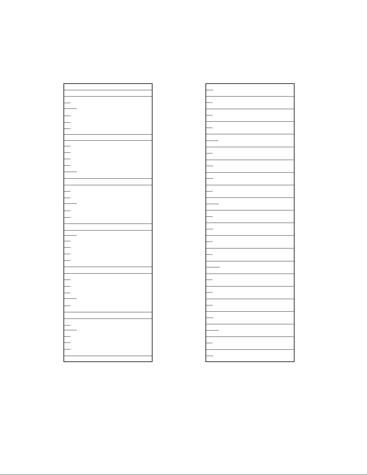
Section 2 — Installation
for the Deflector Assembly at the bottoms (see Figure 2-3). Up to twentytwo 2 RU frames can be installed in a 7 ft. bay, taking up all 44 spaces—no
deflector or fan assemblies are required with the 2 RU frames.
40
35
30
25
20
Fan Assembly
6 RU Frame
Fan Assembly
6 RU Frame
Fan Assembly
6 RU Frame
Fan Assembly
6 RU Frame
(1)
(2)
(3)
(4)
40
35
30
25
20
2 RU Frame
2 RU Frame
2 RU Frame
2 RU Frame
2 RU Frame
2 RU Frame
2 RU Frame
2 RU Frame
2 RU Frame
2 RU Frame
2 RU Frame
2 RU Frame
2 RU Frame
2 RU Frame
(1)
(2)
(3)
(4)
(5)
(6)
(7)
(8)
(9)
(10)
(11)
(12)
(13)
(14)
15
10
Fan Assembly
(5)
6 RU Frame
Fan Assembly
5
6 RU Frame
Deflector Assembly
Maximum 6 RU Frames Maximum 2 RU Frames
Figure 2-3. Maximum 6RU and 2RU Configurations in a 7 ft. Bay
(6)
15
10
5
2 RU Frame
2 RU Frame
2 RU Frame
2 RU Frame
2 RU Frame
2 RU Frame
2 RU Frame
2 RU Frame
(15)
(16)
(17)
(18)
(19)
(20)
(21)
(22)
2-8 MCF Installation and Service
Page 53

Installation of a 2 RU Frame in the Equipment Rack
Installation of a 2 RU Frame in the Equipment Rack
The 2 RU frame installs in a 19-inch (483 mm) equipment rack. A wider 23inch (584 mm) rack can be used with an optional 23-inch mounting bracket
kit (part number MCF-BRK-232). Figure 2-4 illustrates installation of a two
rack system. Four bolts and the appropriate screwdriver are needed for
installation of each frame.
Equipment Rack
Mounting Brackets
MCF Frame
G
r
a
s
s
V
a
lle
y
L
O
C
Mounting
Screws
K
5143-211
G
ra
s
Figure 2-4. Multiple 2 RU Frame Installation in the 19-Inch Equipment Rack
Installing a 2 RU Frame
To install the 2 RU frame in the 19-inch equipment rack, follow these steps:
1. Position the frame in the equipment rack at the desired height.
2. Secure it to the equipment rack with two bolts on each side.
M
s
V
a
lle
y
L
O
C
K
A
J
O
R
A
L
A
R
M
M
I
N
O
R
A
L
A
R
M
L
O
C
K
MCF
Series
M
A
J
O
R
A
L
A
R
M
M
IN
O
R
A
L
A
R
M
L
O
C
K
MCF
Series
You may attach any number of 2 RUs in your equipment rack. The
2 RU frame is self-contained and does not require the fan and deflector
assemblies for cooling.
MCF Installation and Service 2-9
Page 54

Section 2 — Installation
Installing Multiple 2 RU Frames
Making Frame Connections
To install multiple 2 RU frames in the 19-inch equipment rack, see
Figure 2-4. The 2 RU frame is self-contained and does not require the fan
and deflector assemblies for cooling.
With the exceptions of the fiber-optic cable and monitors, all connections
are made at the rear of the frame. See Figure 2-5 for an illustration of a 6 RU
MCF system backplane. These connections for the 6 RU backplane include
the following:
■ Frame ground connections
■ Alarm connections
■ Power connections—DC and AC
■ Fan power connection
■ Video and audio signal connections (9 each)
AC Power Connectors
DC Power Connectors
GRASS VALLEY GROUP, INC.
MODEL: MCF SERIES
MADE IN U.S.A.
VERIFY VOLTAGE SETTING
BEFORE APPLYING POWER
Vor Anschluß on das Netz
DATE OF
MFG
WARNING
Zur Trennung vom Netz
beide Netzanschlu
Leitungen entfernen.
Aufstellanitung beachten!
ß -
RATED VOLTAGE: 100-120VAC~/200-240VAC~/ 48VDC
RATED CURRENT: 6 A MAX / 3 A MAX / 12 A MAX
FREQUENCY: 50-60Hz 50-60Hz
48VDC
GND
–+
J1
IF EQUIPPED WITH REDUNDANT POWER
THIS UNIT HAS TWO POWER CORDS.
TO REDUCE THE RISK OF ELECTRIC
S1
SHOCK, DISCONNECT BOTH POWER
CORDS BEFORE SERVICING.
110 220
J3
120/240 VAC
WARNING
Alarm Connector
THIS DEVICE COMPLIES WITH PART
15 OF THE FCC RULES OPERATION
SUBJECT TO THE FOLLOWING TWO
CONDITIONS: (1) THIS DEVICE MAY
NOT CAUSE HARMFUL INTERFERENCE
(2) THIS DEVICE MUST ACCEPT ANY
INTERFERENCE RECEIVED INCLUDING
INTERFERENCE THAT MAY CAUSE
SLOT
USE
RS485/
RS232
48VDC
ADMIN.
GND
PORT
–+
J01
J2
S2
110 220
J4
120/240 VAC
FAN
POWER
J5
ETL LISTED
E
L
TELEPHONE
T
EQUIPMENT
Conforms to ULSTD 1459
ETL TESTING LABORATORIES, INC.
CORTLAND, NEW YORK, 13045
UNDESIRED OPERATIONS.
CAUTION:
This unit has more than one power source.
Disconnecting power cords
may not de-energize unit.
ATTENTION:
Ca produit a plus qu'une Source de pouvior
electrique. Debranchement n' assure pas
de-energisation de I' equipement.
0
FIBER1AUD/VID
ALARM
J02
J03
EXP
VIDEO
I/O
VIDEO
I/O
RS232
CRAFT
PORT
J04
Video/Audio Connectors
7
6
3
2
AUD/VID
AUDIO/
DATA
GND
-
A
+
GND
-
B
CC
D
IN 1
IN
I/O 1 I/O 2 I/O 3 I/O 4 I/O 5 I/O 6 I/O 7 I/O 8 I/O 9
B
+
GND
-
+
GND
-
D
+
J11
J21
IN 2
J12
J22
J13
J23
AUD/VID
AUDIO/
DATA
IN 3
AUD/VID AUD/VID
GND
-
+
GND
-
+
GND
-
+
GND
-
+
J31
J32
J33
54
AUD/VID
AUDIO/
DATA
GND
-
AA
+
GND
-
B
D
J41
IN 5
IN 4
J42
J43
B
+
GND
-
CC
+
GND
-
D
+
J51
J61
IN 6
J52
J62
J63
J53
AUDIO/
DATA
AUD/VIDAUD/VID
AUDIO/AUDIO/AUDIO/AUDIO/
DATA DATA DATA DATA
GND
-
+
GND
-
+
GND
-
+
GND
-
+
J71
IN 7
IN 8
J72
J73
98
AUD/VID DATA
AUDIO/
DATA
AA
B
C
D
J81
IN 9
J82
J83 J93
5143-201
SLOT
USE
GND
-
+
GND
-
+
GND
-
+
GND
-
+
J91
VIDEO
IN
J92
VIDEO
I/O
Figure 2-5. Backplane Frame for 6 RU
2-10 MCF Installation and Service
Page 55
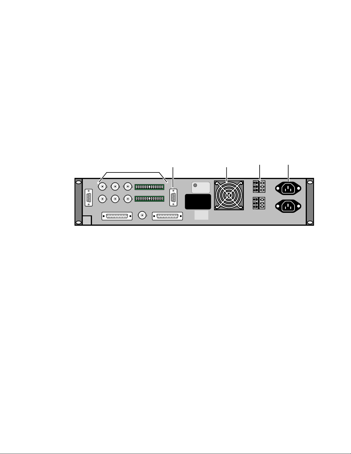
Backplane for the 2 RU Frame
+
–
GND
+
–
GND
J1
J2 J3
J8
J9
J4
J10
J11
J7
J12
J13
J5
J6
THIS DEVICE COMPLIES WITH PART
15 OF THE FCC RULES OPERATION
SUBJECT TO THE FOLLOWING TWO
CONDITIONS: (1) THIS DEVICE MAY
NOT CAUSE HARMFUL INTERFERENCE
(2) THIS DEVICE MUST ACCEPT ANY
INTERFERENCE RECEIVED INCLUDING
INTERFERENCE THAT MAY CAUSE
UNDESIRED OPERATIONS.
ETL LISTED
TELEPHONE
EQUIPMENT
Conforms to ULSTD 1459
ETL TESTING LABORATORIES, INC.
CORTLAND, NEW YORK, 13045
E
L
T
CAUTION:
This unit has more than one power source.
Disconnecting power cords
may not de-energize unit.
ATTENTION:
Ca produit a plus qu'une Source de pouvior
electrique. Debranchement n' assure pas
de-energisation de I' equipement.
5143-200
Video/Audio
Connectors
AC Power
Fan
Alarm
Connector
DC Power
ConnectorsConnectors
With the exceptions of the fiber-optic cable and monitors, all connections
are made at the rear of the frame. These connections for the 2 RU backplane
include the following:
■ Frame ground connections
■ Video and audio signal connections (2)
■ Alarm connections
■ Power connections—DC and AC
See Figure 2-6 for an illustration of a 2 RU system backplane.
Grounding the Frame
Figure 2-6. Backplane for the 2 RU Frame
Grounding the Frame
It is recommended that the chassis of the frame be connected to earth
ground. A grounding connector is provided on the back of each MCF
frame. To make the connection, see Figure 2-7 and perform the following
steps:
1. Loosen the grounding screw.
2. Insert the earth ground wire as shown in Figure 2-7.
MCF Installation and Service 2-11
Page 56

Section 2 — Installation
Earth Ground
Connector
3. Firmly tighten the grounding screw until snug.
Figure 2-7. Earth Ground Wire Attachment
5139-03
Grounding
Screw
Earth Ground Wire
2-12 MCF Installation and Service
Page 57

Making Alarm Connections
C
D
B
AA
B
D
CC
D
B
AA
B
D
CC
D
B
A
SLOT
USE
SLOT
USE
98
AUD/VIDAUD/VID
7
AUD/VID DATA
6
AUD/VID
54
AUD/VID AUD/VID
3
AUD/VID
2
AUD/VID
0
FIBER1AUD/VID
48VDC
FAN
POWER
J5
RS232
CRAFT
PORT
J04
PORT
ADMIN.
RS232
RS485/
J02
AUDIO/AUDIO/AUDIO/AUDIO/
DATA DATA DATA DATA
AUDIO/
+
-
DATA
-
+
GND
GND
GND
-
+
-
+
GND
AUDIO/
-
+
GND
-
GND
+
GND
DATA
+
-
+
-
GND
AUDIO/
-
+
GND
-
GND
+
GND
DATA
+
-
+
-
GND
AUDIO/
-
+
GND
-
GND
+
GND
DATA
+
-
+
-
GND
-
+
GND
-
GND
+
-
+
GND
+
-
GND
DATA
AUDIO/
I/O
EXP
VIDEO
I/O
IN 1
J03
GND
——+
120/240 VAC
120/240 VAC
Leitungen entfernen.
beide Netzanschlu
§ -
Zur Trennung vom Netz
CORDS BEFORE SERVICING.
SHOCK, DISCONNECT BOTH POWER
TO REDUCE THE RISK OF ELECTRIC
THIS UNIT HAS TWO POWER CORDS.
IF EQUIPPED WITH REDUNDANT POWER
WARNING
48VDC
GND
—+
J01
ALARM
J11
J12
J13
J21
J22
J23
J31
J32
J33
J41
J42
J43
IN 2
IN 3
IN 4
J51
J52
IN 5
J61
J62
IN 6
J71
J72
IN 7
J81
J82
IN 8
J91
J92
IN 9
J53
J63
J73
J83 J93
VIDEO
IN
VIDEO
IN
VIDEO
I/O
I/O 1 I/O 2 I/O 3 I/O 4 I/O 5 I/O 6 I/O 7 I/O 8 I/O 9
J2
S2
J4
J1
S1
J3
WARNING
GRASS VALLEY GROUP, INC.
MODEL: MCF SERIES
MADE IN U.S.A.
VERIFY VOLTAGE SETTING
BEFORE APPLYING POWER
Vor Anschlu§ on das Netz
Aufstellanitung beachten!
RATED VOLTAGE: 100-120VAC~/200-240VAC~/ 48VDC
RATED CURRENT: 6 A MAX / 3 A MAX / 12 A MAX
FREQUENCY: 50-60Hz 50-60Hz
DATE OF
MFG
110 220
110 220
THIS DEVICE COMPLIES WITH PART
15 OF THE FCC RULES OPERATION
SUBJECT TO THE FOLLOWING TWO
CONDITIONS: (1) THIS DEVICE MAY
NOT CAUSE HARMFUL INTERFERENCE
(2) THIS DEVICE MUST ACCEPT ANY
INTERFERENCE RECEIVED INCLUDING
INTERFERENCE THAT MAY CAUSE
UNDESIRED OPERATIONS.
ETL LISTED
TELEPHONE
EQUIPMENT
Conforms to ULSTD 1459
ETL TESTING LABORATORIES, INC.
CORTLAND, NEW YORK, 13045
E
L
T
CAUTION:
This unit has more than one power source.
Disconnecting power cords
may not de-energize unit.
ATTENTION:
Ca produit a plus qu’une Source de pouvior
electrique. Debranchement n’ assure pas
de-energisation de I’ equipement.
5158-99
Alarm
Connector
Alarm outputs correspond to the alarm indicators on the front of the power
supplies and MCF system modules. Alarm outputs from the Fiber module
are routed to the ALARM connector on the rear of the frame. See Figure 2-8
for the connector location for a 6 RU frame. See Figure 2-9 for the connector
location for a 2 RU frame.
Making Alarm Connections
Figure 2-8. Backplane Alarm Connections for 6 RU Frame
Alarm
Connector
J7
J8
J13
J9
J12
J2 J3
J1
J10
J4
J5
J6
J11
MCF Installation and Service 2-13
Figure 2-9. Backplane Alarm Connections for 2 RU Frame
NOT CAUSE HARMFUL INTERFERENCE
INTERFERENCE RECEIVED INCLUDING
ETL LISTED
E
L
TELEPHONE
T
EQUIPMENT
Conforms to ULSTD 1459
ETL TESTING LABORATORIES, INC.
CORTLAND, NEW YORK, 13045
THIS DEVICE COMPLIES WITH PART
15 OF THE FCC RULES OPERATION
SUBJECT TO THE FOLLOWING TWO
CONDITIONS: (1) THIS DEVICE MAY
(2) THIS DEVICE MUST ACCEPT ANY
INTERFERENCE THAT MAY CAUSE
UNDESIRED OPERATIONS.
CAUTION:
This unit has more than one power source.
Disconnecting power cords
may not de-energize unit.
ATTENTION:
Ca produit a plus qu'une Source de pouvior
electrique. Debranchement n' assure pas
de-energisation de I' equipement.
GND
+
GND
–
+
–
5158-98
Page 58

Section 2 — Installation
This connector is a DB-9 (9-pin D female) socket connector. It provides relay
closures to ground when an alarm condition exists. A cable from an
external indicator, such as a light, can be attached to this connector. This
cable must be supplied by the customer. Table 2-1 lists the pinouts for the
DB9-F connector.
Table 2-1. Alarm Connector Pinout
Pin Signal
1 Minor Alarm Relay Common
2 Minor Alarm Relay Normally Open
3 Minor Alarm Relay Normally Closed
4 Blank
5 Major Alarm Relay Normally Closed
6 No connection
7 Major Alarm Relay Normally Open
8 Major Alarm Relay Common
9 Earth Ground
Making Power Connections
CAUTION Do not apply power until you have completed all of the cabling procedures.
The rear of the frame provides one of three connector configurations for AC
and DC power sources:
■ two AC,
■ two DC, or
■ one AC and one DC.
Connections of both sources are discussed in the following text. If the frame
has one of each or only one power supply, verify that you are connecting
power to the correct slot location(s) in the frame before making connections.
Verify that the proper type of frame power supply is installed to the power
source in your in your installation.
WARNING Any instructions in this manual that require opening the equipment cover or
enclosure are for use by qualified service personnel only. To reduce the risk
of electric shock, do not perform any servicing other than that contained in
the operating instructions unless you are qualified to do so.
2-14 MCF Installation and Service
Page 59
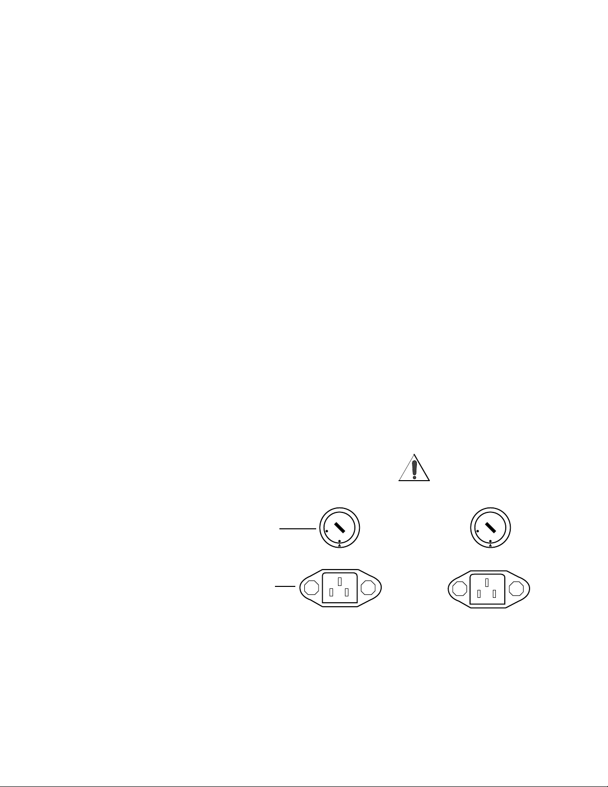
AC Power Connections
The AC power connections for the 2 RU or 6 RU frame are slightly different.
Those difference are noted in the following text.
Six RU Frame
AC power may be connected to either J3 or J4 or both, depending on your
MCF system configuration. Setting the line (source) voltage level is done
with either S1 or S2, or both, again depending on whether you have a
redundant power supply installed. Figure 2-10 illustrates the location of S1
and S2. To connect AC power, see Figure 2-5 (for location of the AC connector on the backplane) and Figure 2-10 (for S1 or S2 location), and
perform the following steps:
CAUTION Set S1 and/or S2 only when the AC power source is disconnected. Changing
the setting with the AC power connected causes catastrophic damage to your
MCF system.
1. Using a small, regular screwdriver, set the Line Voltage
Selector Switch, S1 and/or S2, as shown in Figure 2-10, to the correct
level of AC source power (110 or 220 Volts nominal).
Making Power Connections
2. Attach the socket (female) end of the supplied power cord(s) to the AC
connector(s), J3 and/or J4. If only one supply is installed, ensure the
cord is inserted into a connector that connects to a Power Supply
module. Do not apply power until the remainder of the cabling has
been completed.
WARNING
S1
AC Line Voltage
Selector Switch
220
110
J3
120/240 VAC
AC Source
Connector
Figure 2-10. AC Line (Source) Voltage Selection
IF EQUIPPED WITH REDUNDANT POWER
THIS UNIT HAS TWO POWER CORDS.
TO REDUCE THE RISK OF ELECTRIC
SHOCK, DISCONNECT BOTH POWER
CORDS BEFORE SERVICING.
Zur Trennung vom Netz
beide Netzanschlu
Leitungen entfernen.
ß -
S2
0
2
2
110
J4
120/240 VAC
5143-205
MCF Installation and Service 2-15
Page 60

Section 2 — Installation
Two Rack Unit Frame
3. The AC power supply for the 2 RU frame is auto-ranging. The unit will
adjust itself automatically for 100 or 220 VAC. Simply plug the unit into
the appropriate power source, and the selection is made. See
Figure 2-11 for the AC power connector location. Do not apply power
until the remainder of the cabling has been completed.
J2 J3
J1
J10
J4
J5
J6
J11
J8
J9
J7
Figure 2-11. AC Power Connector for the 2 RU Frame
DC Power Connections
The DC power connections for the 2 RU and 6 RU frames are identical. The
installation process is noted in the following text.
DC Power for the 6 RU Frame
DC power may be connected to either J1 or J2 or both, depending on the
system configuration. Connect to a 48 VDC Safety Extra-Low Voltage
(SELV) source (as defined by Underwriter’s Laboratories) or to a 48 VDC
source that is electrically isolated from the AC source and is reliably connected to earth.
To connect DC power, see Figure 2-5 (for location of the DC connector on
the backplane) and Figure 2-12 for location of the DC positive (+) and negative (–) connectors. Perform the following steps:
J12
J13
ETL LISTED
E
L
TELEPHONE
T
EQUIPMENT
Conforms to ULSTD 1459
ETL TESTING LABORATORIES, INC.
CORTLAND, NEW YORK, 13045
THIS DEVICE COMPLIES WITH PART
15 OF THE FCC RULES OPERATION
SUBJECT TO THE FOLLOWING TWO
CONDITIONS: (1) THIS DEVICE MAY
NOT CAUSE HARMFUL INTERFERENCE
(2) THIS DEVICE MUST ACCEPT ANY
INTERFERENCE RECEIVED INCLUDING
INTERFERENCE THAT MAY CAUSE
UNDESIRED OPERATIONS.
CAUTION:
This unit has more than one power source.
Disconnecting power cords
may not de-energize unit.
ATTENTION:
Ca produit a plus qu'une Source de pouvior
electrique. Debranchement n' assure pas
de-energisation de I' equipement.
+
GND
–
+
GND
–
5158-98
AC Power
Connectors
1. Ensure that the 48 VDC Power source is turned off.
2. Using a small, flat-blade screwdriver, loosen the three screws in the 48
VDC connector (J1).
3. Strip enough of the ends of the wires from the 48 VDC power source to
allow easy insertion into the DC connector on the MCF backplane.
2-16 MCF Installation and Service
Page 61

Making Power Connections
4. Insert the positive (+) and negative (–) wires from the –48 VDC power
source into the appropriate connector slots and tighten the screws
previously loosened in Step 1.
5139-04
Figure 2-12. DC Power Connection Detail
+
48VDC
GN
D
J1
5. If desired, a NRZ may be used between the GND connection and either
the + or – connection.
a. Connect the jumper between GND and + if your 48 VDC supply has
its positive side tied to earth ground.
or
b. Connect the jumper between GND and – if your 48 VDC supply has
its negative side tied to earth ground.
6. Tighten all screws in the connector to secure the DC leads.
Note Do not connect the DC power cord to the DC source power at this time. Frame
Power is applied when making source power connection at the end of the
installation process.
DC Power for the 2 RU Frame
Do not connect the DC power cord to the source power at this time. Simply
plug the unit into the appropriate frame and the DC selection is made. See
Figure 2-13 for the DC power connector location.
MCF Installation and Service 2-17
Page 62

Section 2 — Installation
See Steps 1 through 6 to make the DC power connections.
DC Power
Connectors
J2 J3
J1
J10
J4
J5
J11
Figure 2-13. DC Power Connector for the 2 RU Frame
Fan Power Connection
The fan power connection on the 6 RU frame is described in the following
text. The 2 RU frame has the exhaust fan mounted directly on the backplane—the fan is in place and powered when the frame is powered. For the
2 RU frame, no fan installation instructions are required.
Fan for the 6 RU Frame
To connect power to the exhaust fan assembly, a cable is provided with the
frame. (This cable is approximately 15 inches long.)
1. Attach the fan power cable to the FAN POWER connector, J5, on the
rear of the MCF frame.
J8
J6
J9
J7
J13
J12
ETL LISTED
E
L
TELEPHONE
T
EQUIPMENT
Conforms to ULSTD 1459
ETL TESTING LABORATORIES, INC.
CORTLAND, NEW YORK, 13045
THIS DEVICE COMPLIES WITH PART
15 OF THE FCC RULES OPERATION
SUBJECT TO THE FOLLOWING TWO
CONDITIONS: (1) THIS DEVICE MAY
NOT CAUSE HARMFUL INTERFERENCE
(2) THIS DEVICE MUST ACCEPT ANY
INTERFERENCE RECEIVED INCLUDING
INTERFERENCE THAT MAY CAUSE
UNDESIRED OPERATIONS.
CAUTION:
This unit has more than one power source.
Disconnecting power cords
may not de-energize unit.
ATTENTION:
Ca produit a plus qu'une Source de pouvior
electrique. Debranchement n' assure pas
de-energisation de I' equipement.
+
GND
–
+
GND
–
5158-98
2-18 MCF Installation and Service
Page 63

Making Signal Connections
C
D
B
AA
B
D
CC
D
B
AA
B
D
CC
D
B
A
SLOT
USE
SLOT
USE
98
AUD/VIDAUD/VID
7
AUD/VID DATA
6
AUD/VID
54
AUD/VID AUD/VID
3
AUD/VID
2
AUD/VID
0
FIBER1AUD/VID
48VDC
FAN
POWER
J5
RS232
CRAFT
PORT
J04
PORT
ADMIN.
RS232
RS485/
J02
AUDIO/AUDIO/AUDIO/AUDIO/
DATA DATA DATA DATA
AUDIO/
+
-
DATA
-
+
GND
GND
GND
-
+
-
+
GND
AUDIO/
-
+
GND
-
GND
+
GND
DATA
+
-
+
-
GND
AUDIO/
-
+
GND
-
GND
+
GND
DATA
+
-
+
-
GND
AUDIO/
-
+
GND
-
GND
+
GND
DATA
+
-
+
-
GND
-
+
GND
-
GND
+
-
+
GND
+
-
GND
DATA
AUDIO/
I/O
EXP
VIDEO
I/O
IN 1
J03
GND
——+
120/240 VAC
120/240 VAC
Leitungen entfernen.
beide Netzanschlu
§ -
Zur Trennung vom Netz
CORDS BEFORE SERVICING.
SHOCK, DISCONNECT BOTH POWER
TO REDUCE THE RISK OF ELECTRIC
THIS UNIT HAS TWO POWER CORDS.
IF EQUIPPED WITH REDUNDANT POWER
WARNING
48VDC
GND
—+
J01
ALARM
J11
J12
J13
J21
J22
J23
J31
J32
J33
J41
J42
J43
IN 2
IN 3
IN 4
J51
J52
IN 5
J61
J62
IN 6
J71
J72
IN 7
J81
J82
IN 8
J91
J92
IN 9
J53
J63
J73
J83 J93
VIDEO
IN
VIDEO
IN
VIDEO
I/O
I/O 1 I/O 2 I/O 3 I/O 4 I/O 5 I/O 6 I/O 7 I/O 8 I/O 9
J2
S2
J4
J1
S1
J3
WARNING
GRASS VALLEY GROUP, INC.
MODEL: MCF SERIES
MADE IN U.S.A.
VERIFY VOLTAGE SETTING
BEFORE APPLYING POWER
Vor Anschlu§ on das Netz
Aufstellanitung beachten!
RATED VOLTAGE: 100-120VAC~/200-240VAC~/ 48VDC
RATED CURRENT: 6 A MAX / 3 A MAX / 12 A MAX
FREQUENCY: 50-60Hz 50-60Hz
DATE OF
MFG
110 220
110 220
THIS DEVICE COMPLIES WITH PART
15 OF THE FCC RULES OPERATION
SUBJECT TO THE FOLLOWING TWO
CONDITIONS: (1) THIS DEVICE MAY
NOT CAUSE HARMFUL INTERFERENCE
(2) THIS DEVICE MUST ACCEPT ANY
INTERFERENCE RECEIVED INCLUDING
INTERFERENCE THAT MAY CAUSE
UNDESIRED OPERATIONS.
ETL LISTED
TELEPHONE
EQUIPMENT
Conforms to ULSTD 1459
ETL TESTING LABORATORIES, INC.
CORTLAND, NEW YORK, 13045
E
L
T
CAUTION:
This unit has more than one power source.
Disconnecting power cords
may not de-energize unit.
ATTENTION:
Ca produit a plus qu’une Source de pouvior
electrique. Debranchement n’ assure pas
de-energisation de I’ equipement.
5158-99
Fan Power
Connector
2. Connect the other end of the power cable to the power connector on the
fan assembly. Note that the connectors are keyed to prevent mismating.
See Figure 2-14 for connector location.
Figure 2-14. Backplane Fan Power Connector for 6 RU Frame
Making Signal Connections
Signal connections consist of video and audio signal connectors and the
fiber-optic connector. If a terminal is to be used (recommended but not
required), signal connections include those for Craft and Administration
port connectors. These connections are described in the following text.
Note The EXP I/O port (J03 on the 6 RU frame, and J7 on the 2 RU frame) is for
factory use only.
Administration Port Connection
MCF Installation and Service 2-19
The RS-485/RS-232 ADMIN PORT connector (J01 on the 6 RU frame, and
J12 on the 2 RU frame) is a DB-25F socket connector. This connector connects the frame to a computer. A commercially available 25-pin, null
modem cable may be used for the RS-232 application; however, the RS-485
cable must be constructed. The pinouts for both cables are listed in
Table 2-2.
Page 64

Section 2 — Installation
Table 2-2. RS-232/RS-485 Administration Port J01 Pinouts
Pin Direction RS-232 Signal RS-485 Signal
1 ---- Earth Ground Earth Ground
2 Out TX Data TX Data+
3 In RX Data RX Data+
4 Out RTS (request to send) NC (no connection)
5 In CTS (clear to send) NC
6 In DSR (data set ready) NC
7 ---- Signal Ground Signal Ground
8–13 ---- NC (no connection) NC
14 Out NC TX Data–
15 ---- NC NC
16 In NC RX Data–
17–19 ---- NC NC
20 Out DTR (data terminal ready) NC
21–25 ---- NC NC
RS-485 Communication
To preserve the shape and integrity of a waveform traveling along a cable,
the cable must be terminated in an impedance equal to its characteristic
impedance. In a system such as this, where data travels in both directions,
both physical ends of the cable must be terminated into a 120 Ohm impedance. Stubs leading to each Transmitter should be as short as possible.
Circuit ground of all transmitters must be connected via a dedicated wire
within the cable.
Leaving off the terminations generally results in reflections that can have
amplitudes of several volts above V
and undershoots can disrupt the Transmitter operation, create false data,
and in some cases possibly damage components on the bus.
or below ground. These overshoots
CC
2-20 MCF Installation and Service
Page 65

Making Signal Connections
Figure 2-15 illustrates an example of RS-485 cabling.
Customer’s
Master
Controller
+5V
R
*
B
RT*
R
B
MCF #1
Notes:
R
= 120Ω at each end of the cable.
T
RB>>R
T
RT* may be located inside the customer’s
master controller.
* biasing for the transmission line
R
B
must be provided by the customer’s
master controller.
User is responsible for all cabling beyond
the transceivers and the dotted lines.
Figure 2-15. RS-485 Communications Cabling
MCF #2
R
T
MCF #3
MCF Installation and Service 2-21
Page 66
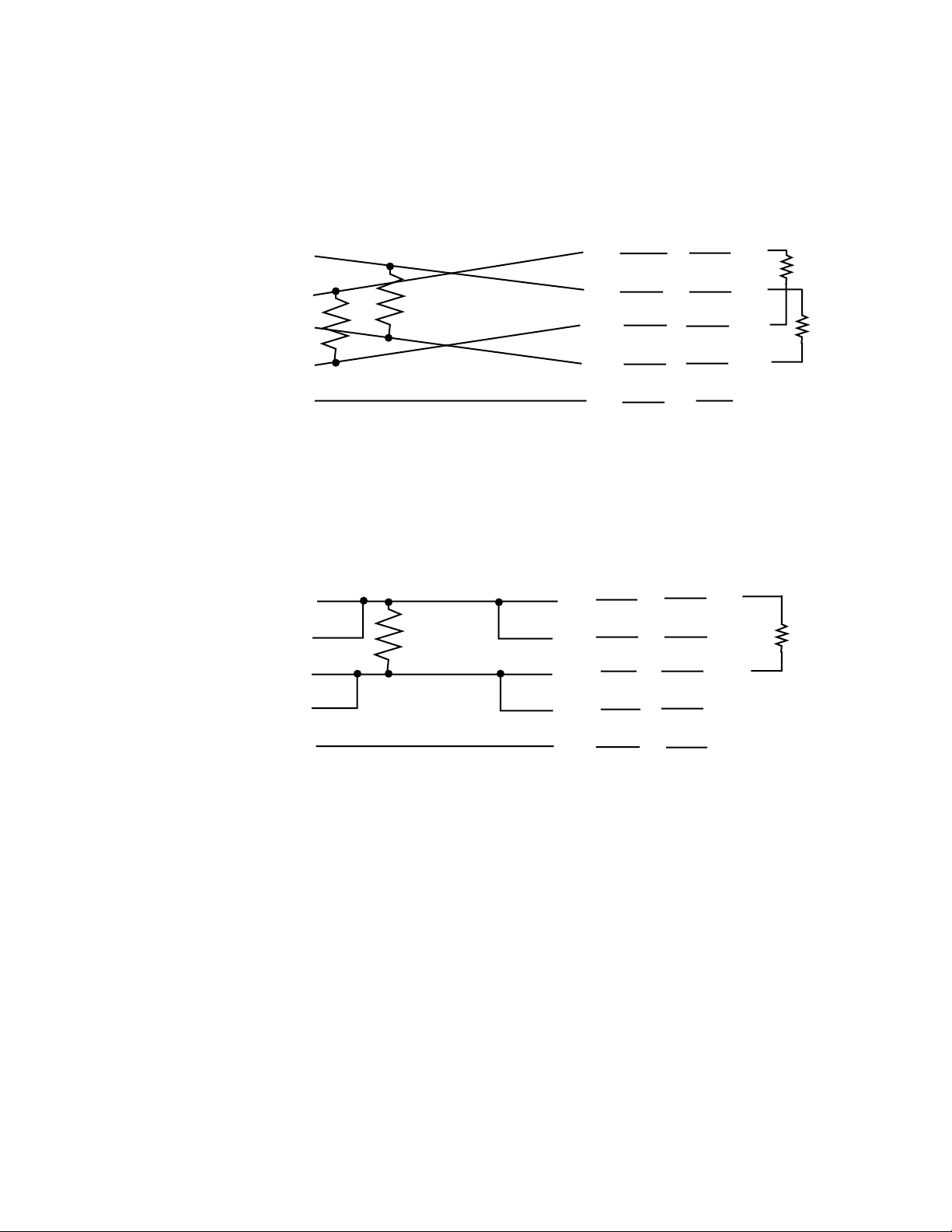
Section 2 — Installation
See Figures 2-5 (for 6 RU frame) or 2-6 (for 2 RU frame) and Figures 2-16 or
2-17 for connecting and cabling information. Figure 2-16 is for a 4-wire
cable and Figure 2-17 is for a 2-wire cable.
Master
T
x+
R
x+
R
T
x-
R
x-
T
R
T
Gnd
Figure 2-16. Four-Wire RS-485 Cable Pinouts
Master
T
x+
R
x+
R
T
MCF Connector MCF
Pin 2
Pin 3
Pin 14
Pin 16
Pin 7
T
x+
R
x+
T
x-
R
x-
Gnd
Pin 2
Pin 3
Pin 14
Pin 16
Pin 7
Note:
R
= 120Ω, two at each end of the cable
T
MCF Connector MCF
Pin 2
Pin 3
T
x+
R
x+
Pin 2
Pin 3
R
T
R
T
R
T
T
x-
R
x-
Gnd
Figure 2-17. Two-Wire RS-485 Cable Pinouts
Pin 14
Pin 16
Pin 7
T
x-
R
x-
Gnd
Pin 14
Pin 16
Pin 7
Notes:
R
= 120Ω at each end of the cable
T
You must jumper connections.
2-22 MCF Installation and Service
Page 67
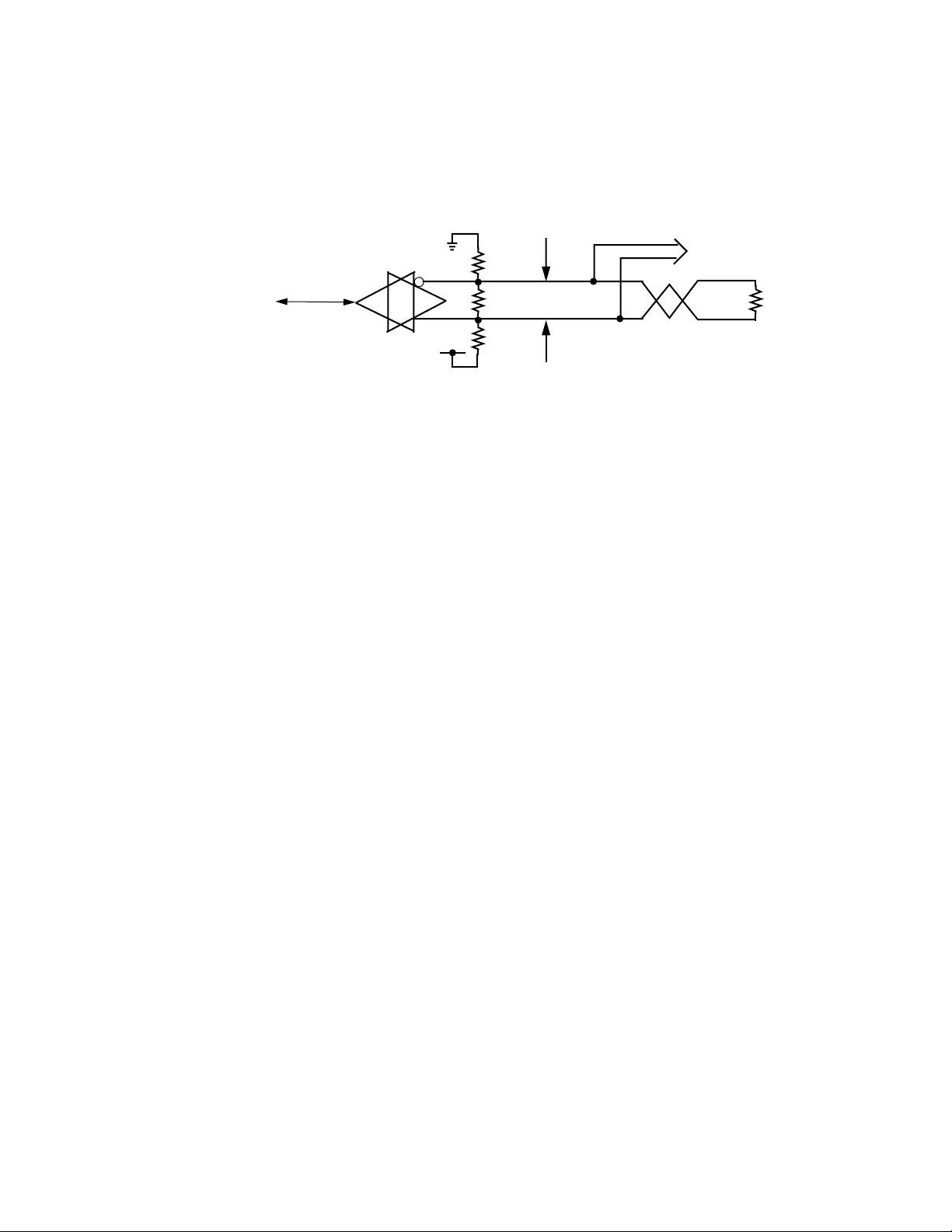
Making Signal Connections
Biasing RS-485
Biasing is required to force –200mV for VAB to generate a line idle condition. See Figure 2-18.
Customer’s
Master
Controller
+5V
Figure 2-18. Single Node Bias — Normal Termination
RS-232 Communication
Figure 2-19 illustrates how the serial data signals at the MCF interconnect
with those of the peripheral equipment. Pin numbering varies widely with
RS-232 implementation; therefore, only numbering for the Administration
port connection is shown. A standard RS-232 null modem cable may work
in many cases. Note that the names of the RS-232 signals depend on
whether they are being received or transmitted. For example, TX Data
leaving the peripheral equipment is renamed RX Data where it is received
at the MCF unit.
To other nodes on the
network with no bias
R
B
V
T
B
AB
-200mV
Notes:
RT = 120Ω
R
= 620Ω
B
If RB were installed at every node on a 32
node network, it would add a 39Ω load to
the transmission line. This is not desirable.
R
R
resistors installed.
R
T
Data connections are provided through a connector serving a bidirectional
channel. The data signal interface conforms to the RS-232-C
standard. (The
EIA standard on Interface Between Data Terminal Equipment and Data
Communication Equipment Employing Binary Data Exchange.)
MCF Installation and Service 2-23
Page 68

Section 2 — Installation
Make interconnections as illustrated in Figure 2-19.
Peripheral
Equipment
Rx Data
Tx Data
RTS
CTS
Administration
Rx Data
Tx Data
RTS
CTS
Port
3
2
4
5
DSR
DSR
6
DTR
DTR
20
Signal Ground
7
25-Pin
Plug
(Male)
Figure 2-19. RS-232 Administration Port Cabling Interface
The RS-232 Administration port connector (J01 on the 6 RU frame, and J12
on the 2 RU frame) is a DB25-F socket connector. It connects the MCF frame
to a computer. The cable for the Administration port must be constructed
by the customer. The tabled titled RS-232/RS-485 Administration Port J01
Pinouts on page 2-20 lists the pinouts.
The minimum configuration for the Administration port RS-232 communication is illustrated in Figure 2-20.
Peripheral
Equipment
Rx Data
Tx Data
Signal Ground
Administration
Rx Data
Tx Data
Port
3
2
7
25-Pin
Socket
(Female)
Figure 2-20. Minimum RS-232 Administration Port Cable
2-24 MCF Installation and Service
Page 69

Craft Port Connection
Figure 2-21 shows how the serial data signals at the frame’s Craft port
interconnect with those of the peripheral equipment. Because pin numbering varies widely with RS-232 implementation, only numbering for the
Craft port connection is shown. Note that the names of the RS-232 signals
depend on whether they are being received or transmitted. For example,
TX Data leaving the peripheral equipment is renamed RX Data where it is
received at the MCF unit.
Making Signal Connections
Data connections are provided through a connector serving a bidirectional
channel. The data signal interface conforms to the RS-232-C
standard. (The
Electronic Industries Association Recommended Standard RS-232-C, Interface Between Data Terminal Equipment and Data Communication Equipment Employing Binary Data Exchange.) Make interconnections for the 9pin connector for either the 6 RU or 2 RU frames as illustrated in
Figure 2-21.
Peripheral
Equipment
Rx Data
6 or 2 RU
Craft Port
Rx Data
2
Tx Data
Tx Data
3
RTS
CTS
RTS
CTS
7
8
Signal Ground
5
9-Pin
Plug
Figure 2-21. Craft Port Connector Pinout (9-pin plug) for 6 or 2 RU Frame
MCF Installation and Service 2-25
Page 70
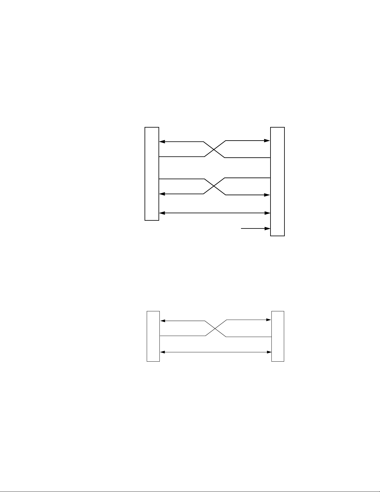
Section 2 — Installation
CAUTION On the 2 RU frame, you may use either the 9-pin or the 25-pin Craft port con-
nector , but you may not use both for communication purposes. If you do, your
system will malfunction.
The 2 RU frame backplane has a 9-pin and a 25-pin connector for Craft port
communication. The 9-pin connector is J10; the 25-pin connector is J11. See
Figure 2-22 for 25-pin connector.
Peripheral
Equipment
Rx Data
Rx Data
2 RU
Craft Port
2
Tx Data
Tx Data
3
RTS
CTS
RTS
CTS
5
4
Signal Ground
7
Chassis Ground
Figure 2-22. Two RU Frame Craft Port Connector Pinout (25-pin plug)
The minimum configuration for the Craft port communication for either
the 6 RU or 2 RU frame is illustrated in Figure 2-23.
1
25-Pin
Plug
Peripheral
Equipment
Rx Data
Tx Data
Rx Data
Tx Data
Signal Ground
Craft Port
2
3
5
9-Pin
Plug
Figure 2-23. Minimum Craft Port Configuration
The 9-pin RS-232 Craft Port connector (J04 on the 6 RU frame, and J10 on
the 2 RU frame) is a DB9-M plug connector. It connects the frame to a terminal. The cable for the Craft port must be constructed. The pinouts are
2-26 MCF Installation and Service
Page 71

Making Signal Connections
listed in Table 2-3. Note that the 2 RU frame has DB25-M Craft connector
(J11) also. The pinout information for the 25-pin connector is found in
Table 2-3.
Table 2-3. RS-232 Craft Port DB9-M Pinouts
Pin Direction Signal
1 ---- No connection
2 In RX Data
3 Out TX Data
4 ---- No connection
5 ---- Signal Ground
6 ---- No connection
7 Out RTS (ready to send)
8 In CTS (clear to send)
9 ---- No connection
The RS-232 25-pin Craft Port connector (J11 on the 2 RU frame) is a DB25M plug connector. It connects the frame to a terminal. The cable for the
Craft port must be constructed. The pinouts are listed in Table 2-4.
Table 2-4. RS-232 Craft Port DB25-M Pinouts
Pin Direction Signal
1 ---- Chassis Ground
2 In RX Data
3 Out TX Data
4 In CTS (clear to send)
5 Out RTS (ready to send)
6 ---- No connection
7 --- Signal Ground
8-25 --- No connection
MCF Installation and Service 2-27
Page 72

Section 2 — Installation
Video Connections
Video connections to the rear of the frame are made with BNC coaxial
cables that are not supplied with your system. The number of cables and
the number of connections are determined by the system configuration. See
Figure 2-24 for connector locations on the 6 RU frame. BNC connectors IN
1 through 9 are used for loop-through.
GRASS VALLEY GROUP, INC.
MODEL: MCF SERIES
MADE IN U.S.A.
WARNING
VERIFY VOLTAGE SETTING
BEFORE APPLYING POWER
Vor Anschlu§ on das Netz
RATED VOLTAGE: 100-120VAC~/200-240VAC~/ 48VDC
RATED CURRENT: 6 A MAX / 3 A MAX / 12 A MAX
FREQUENCY: 50-60Hz 50-60Hz
48VDC
GND
—+
J1
S1
110 220
J3
120/240 VAC
Aufstellanitung beachten!
DATE OF
MFG
WARNING
IF EQUIPPED WITH REDUNDANT POWER
THIS UNIT HAS TWO POWER CORDS.
TO REDUCE THE RISK OF ELECTRIC
SHOCK, DISCONNECT BOTH POWER
CORDS BEFORE SERVICING.
Zur Trennung vom Netz
§ -
beide Netzanschlu
Leitungen entfernen.
48VDC
GND
J2
S2
110 220
J4
120/240 VAC
Figure 2-24. Backplane Video Connections for the 6 RU Frame
See Figure 2-25 for Video BNC connector locations on the 2 RU frame. BNC
connectors J2-J3 and J5-J6 are used for loop-through.
E
L
T
Conforms to ULSTD 1459
ETL TESTING LABORATORIES, INC.
CORTLAND, NEW YORK, 13045
THIS DEVICE COMPLIES WITH PART
15 OF THE FCC RULES OPERATION
SUBJECT TO THE FOLLOWING TWO
CONDITIONS: (1) THIS DEVICE MAY
NOT CAUSE HARMFUL INTERFERENCE
(2) THIS DEVICE MUST ACCEPT ANY
INTERFERENCE RECEIVED INCLUDING
INTERFERENCE THAT MAY CAUSE
UNDESIRED OPERATIONS.
CAUTION:
This unit has more than one power source.
Disconnecting power cords
may not de-energize unit.
ATTENTION:
Ca produit a plus qu’une Source de pouvior
electrique. Debranchement n’ assure pas
de-energisation de I’ equipement.
SLOT
USE
RS485/
RS232
ADMIN.
PORT
—+
J01
FAN
POWER
J5
Video BNC
Connectors
ETL LISTED
TELEPHONE
EQUIPMENT
6
AUD/VID AUD/VID
-
+
-
+
-
+
-
+
IN 4
54
AUD/VID
AUDIO/
DATA
GND
-
AA
+
GND
-
B
+
GND
-
+
GND
-
D
+
J41
J51
IN 5
IN 6
J42
J52
J43
J53
3
0
FIBER1AUD/VID
ALARM
J02
J03
EXP
VIDEO
I/O
VIDEO
RS232
CRAFT
PORT
J04
2
AUD/VID
AUD/VID
AUDIO/
DATA
B
CC
D
IN 1
IN
I/O 1 I/O 2 I/O 3 I/O 4 I/O 5 I/O 6 I/O 7 I/O 8 I/O 9
I/O
AUDIO/
DATA
GND
-
+
GND
-
+
GND
-
+
GND
-
+
J11
J12
J13
GND
A
GND
B
GND
GND
D
J21
J31
IN 2
IN 3
J22
J32
J23
J33
5158-99
7
AUDIO/
DATA
GND
GND
B
GND
CC
GND
D
J61
J71
IN 7
J62
J72
J63
J73
98
SLOT
AUD/VID DATA
AUDIO/
DATA
AA
B
C
D
J81
IN 9
J82
J83 J93
USE
GND
-
+
GND
-
+
GND
-
+
GND
-
+
J91
VIDEO
IN
J92
VIDEO
I/O
Video BNC
Connectors
AUD/VIDAUD/VID
AUDIO/AUDIO/AUDIO/AUDIO/
DATA DATA DATA DATA
-
+
-
+
-
+
-
+
IN 8
J2 J3
J1
J10
J4
J5
J6
J11
J8
J13
J9
J7
J12
ETL LISTED
E
L
TELEPHONE
T
EQUIPMENT
Conforms to ULSTD 1459
ETL TESTING LABORATORIES, INC.
CORTLAND, NEW YORK, 13045
THIS DEVICE COMPLIES WITH PART
15 OF THE FCC RULES OPERATION
SUBJECT TO THE FOLLOWING TWO
CONDITIONS: (1) THIS DEVICE MAY
NOT CAUSE HARMFUL INTERFERENCE
(2) THIS DEVICE MUST ACCEPT ANY
INTERFERENCE RECEIVED INCLUDING
INTERFERENCE THAT MAY CAUSE
UNDESIRED OPERATIONS.
CAUTION:
This unit has more than one power source.
Disconnecting power cords
may not de-energize unit.
ATTENTION:
Ca produit a plus qu'une Source de pouvior
electrique. Debranchement n' assure pas
de-energisation de I' equipement.
+
GND
–
+
GND
–
5158-98
Figure 2-25. Backplane Video Connections for the 2 RU Frame
Serial Digital Video Connections
Using the Serial Digital module’s video connections when on the 6 RU
frame require that you use the lower Video I/O BNC connectors (I/O 1
through 9), not the loop-through connectors (IN 1 through 9). However,
2-28 MCF Installation and Service
Page 73

connectors IN 1–9 can be used one at a time (not as loop-through) for I/O
monitoring. See Figure 2-24 to see where the Video I/O connectors are
located.
On the 2 RU frame, when using a Serial Digital module, video connections
use J1 and J4. Connectors J2-J3 and J5-J6 can be used for I/O monitoring.
(Not as loop-through).
Other Video Connections
At the Transmitter frame, video connections are made from video sources
to one of the loop-through VIDEO IN paired BNC connectors on the Transmitter frame’s backplane. On the 6 RU frame these connectors are numbered as follows:
■ J11-J12 ■ J21-J22
■ J31-J32 ■ J41-42
■ J51-J52 ■ J61-J62
■ J71-J72 ■ J81-J82
Making Signal Connections
■ J91-J92
On the 2 RU frame the video connectors are numbered as follows:
■ J2-J3 ■ J5-J6
It is important to note that the unused connector of each pair must be terminated into 75 Ohm (or have an internal 75 Ohm termination enabled on
the Video Input module jumper J11).
It is also important to note that the DC Restore function should be enabled
by placing jumper J13 (also located on the Video Input module) in the ON
position. This is the factory default setting.
Note that jumper settings should always be checked before installing modules.
The actual number of connections depends on your system configuration.
MCF Installation and Service 2-29
Page 74

Section 2 — Installation
NRZ and NRZI Modes and Compatibility
Incompatible Systems
Recent production MCF Transmitters operate in two modes: Non-return to
zero (NRZ) and non-return to zero, inverted (NRZI). Earlier-generation
MCF Transmitters operate in NRZ mode only. Depending on when they
were manufactured, some MCF Receivers operate only in NRZ mode while
others operate only in NRZI mode. See the following two paragraphs and
Table 2-5 for a quick reference on compatibility of various transmitter and
receiver pairs. Also see Table 2-6 for similar data with greater detail on
board modification and NRZ versus NRZI modes of operation.
The following systems are incompatible:
■ A new 160293-00 Transmitter (set to NRZ mode) or 160293-01 with an
old 066040 -00, -01, -10, -20, -21 Receiver.
■ An old 066039 Transmitter with a new 160294-00, -01 Receiver.
Compatible Systems
■ An old 066039 Transmitter and an old 066040 Receiver (except 066040-
30).
■ A modified 066039-series Transmitter with a new 160294-00, -01
Receiver or old 066040-30 Receiver.
■ A new 160293-00 Transmitter (set to NRZI mode) and an old 066040-
series Receiver (except 066040-30).
■ A new 160293-00 Transmitter (set to NRZ mode) or 160293-01 and an
old 066040-00, -01, -10, -20, -21 modified Receiver or an 066040-30
Receiver.
2-30 MCF Installation and Service
Page 75

Making Signal Connections
Table 2-5. Compatibility of Various Transmitter and Receiver Pairs
Transmitter Receiver Compatibility
066039 066040 (except 066040-30) Compatible
066039-series (if modified) 160294-00 Compatible
066039-series (if modified) 160294-01 Compatible
066039-series (if modified) 066040-30 Compatible
160293-00 (set to NRZI mode) 066040 (except 066040-30) Compatible
160293-00 (set to NRZ mode)
or 160293-01
160293-00 (set to NRZ mode) 066040-30 Compatible
160293-01 066040-30 Compatible
160293-01
160293-00 (Set to NRZ mode) 066040-series (except -30) Incompatible
160293-01 066040-series (except -30) Incompatible
066039-series (unmodified) 160294-00 Incompatible
066039-series (unmodified) 160294-01 Incompatible
066040-series (except -30, if
modified)
066040-series (except -30, if
modified)
Compatible
Compatible
Table 2-6. Receivers and Transmitters in NRZ and NRZI Modes
Part Number Name Mode Early Recent Comments
066039-00 Fiber, Tx NRZI X Note
a
066039-01 Fiber, 10, Tx NRZI X “
066039-10 Fiber, TX 1310 nm, 0dbm NRZI X “
066039-11 Fiber, TX 1310 nm, 0dbm, SC NRZI X “
066039-30 Fiber, Tx, 1550 nm, 0dbm NRZI X “
160293-00 Fiber, Tx, 1310 nm NRZ / NRZI X (jumper)
160293-01 Fiber, Tx, 1310 nm NRZ Only X
160267-00 Fiber, Tx, 1550 nm NRZ / NRZI X (jumper)
066040-00 Fiber, Rx NRZI X Note
b
066040-01 Fiber, 10, Rx NRZI X “
066040-10 Fiber, Rx NRZI X “
066040-20 Fiber, Rx, 29dbm, FC NRZI X “
060040-21 Fiber, Rx, 29dbm, SC NRZI X “
066040-30 Fiber, Rx NRZ only X Note
c
160294-00 Fiber, Rx NRZ Only X
160294-01 Fiber, Rx NRZ only X “
a
Board can be modified for NRZ operation as specified in this section. All of these boards use Vitesse VSC7101.
b
Board can be modified for NRZ operation as specified in this section. All of these boards use Vitesse VSC7102.
c
These boards use Vitesse VSC7106. This part does not have provision for NRZ / NRZI selection. It is capable
of operating only in the NRZ mode.
MCF Installation and Service 2-31
Page 76

Section 2 — Installation
Modification of 066039-00 and -01 Transmitters
MODULE
FRONT
For the early-production Transmitter module (GVP Part # 066039-00 and -
01) to interface correctly with the new Receiver modules (160294-00, -01),
you must make a modification. You must lift resistor R38 and attach a wire
from the lifted side of resistor R38 to the PECLL side of resistor R41. See
Figure 2-26 for the location of these two resistors.
R39
R38
R40
R41
R40
R41
GVG
FIBER TX
066039 —
®
2. Attach a wire from lifted
1. Lift top side
of resistor R38
side of R38 to top
side of R41
CONNECTOR
REAR
R39
R38
Figure 2-26. MCF Transmitter 066039 -00 and -01 Modification
CAUTION You need special skills and equipment to change surface-mount parts in the
field. For detailed information about Surface Mount Part replacement, refer to
the ANSI/IPC-R-700, Suggested Guidelines for Modification, Rework and
Repair of Printed boards and Assemblies (Sections 5.1.4.3, 5.1.10, 5.1.10.1,
5.1.10.2, 5.1.10.3 and 5.4.1 through 5.4.5). Any damage incurred to the
module or its components as a result of the installation of this modification is
entirely the responsibility of the customer and may void the warranty.
2-32 MCF Installation and Service
Page 77
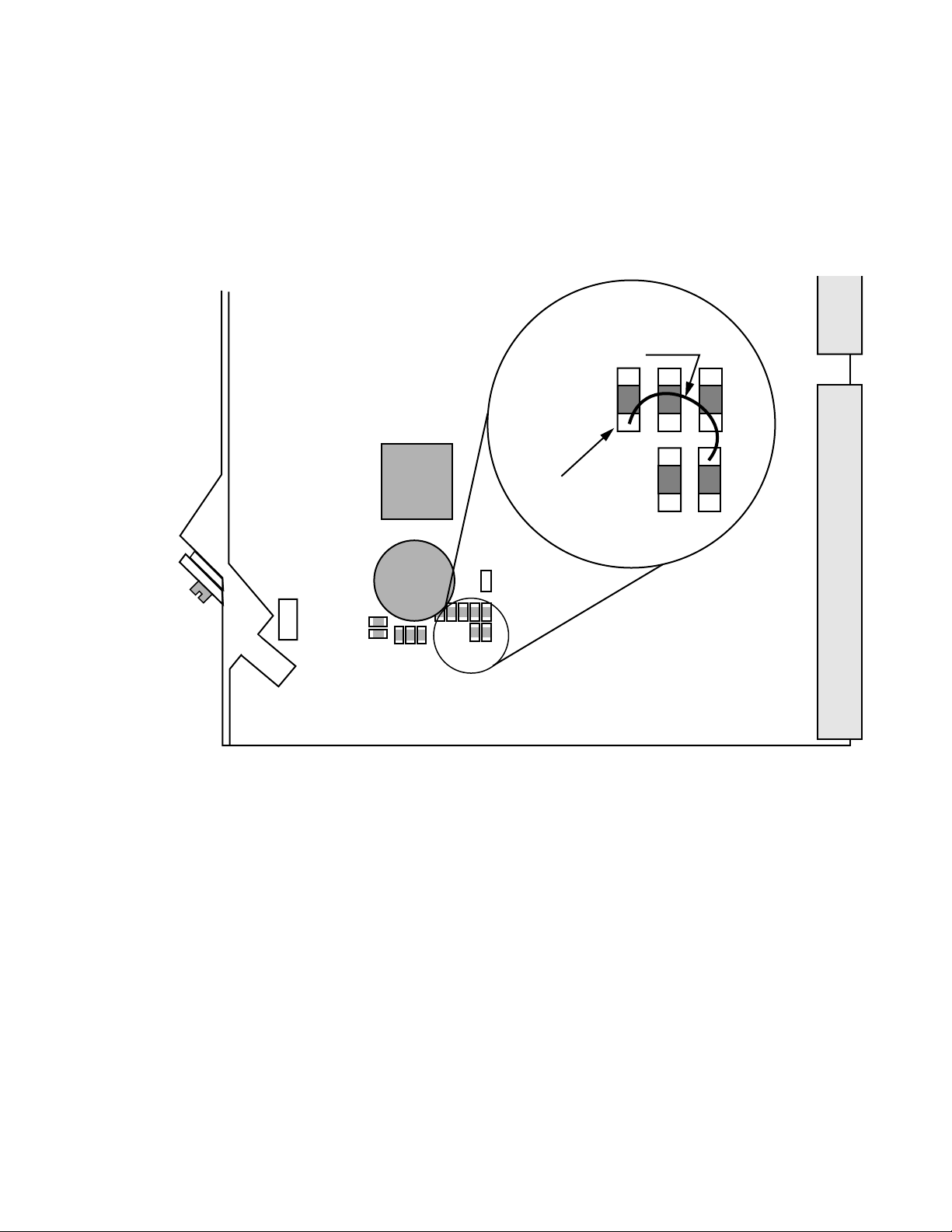
Making Signal Connections
GVG
®
FIBER TX
066039 —
R113
R107
C76
R111
R112
R104
R105
C72
R110
C75
REAR
CONNECTOR
1. Lift bottom side
2. Attach a wire from lifted
side of R104 to top
side of R110
R110
C75
R104
of resistor R104
MODULE
FRONT
MADE IN U.S.A.
Modification of 066039-10, -11, and -30 Transmitters
For the early-production Transmitter module (GVP Part # 066039-10, -11,
and -30) to interface correctly with the new Receiver modules (160294-00, -
01), you must make a modification. You must lift resistor R104 and attach a
wire from the lifted side of resistor R104 to the PECLL side of resistor R110.
See Figure 2-27 for the location of these two resistors.
Figure 2-27. MCF Transmitter 066039 -10, -11, and -30 Modification
MCF Installation and Service 2-33
Page 78

Section 2 — Installation
Modification of 066040-00, -01, -10, -20, and -21 Receivers
MODULE
FRONT
Early-production Receiver modules (GVP part # 066040-00, -01, -10, -20,
and -21) operate only in NRZI mode. If you wish to use a new 160293-00, or
-01 Transmitter with any of these old Receivers, set the new Transmitter’s
jumper to the NRZI mode. See Figure 2-29 on page 2-35 for detailed information.
If you wish to operate any of these old Receiver types with a new 16029300 or -01 Transmitter in NRZ mode, modify the Receiver as shown in Figure
2-28 and as follows. Remove R53 and add a wire from R46 (ECLL side) to
U30 pin 24 (VSC7102 NRZ/NRZI pin.)
.
R43
R23
R79
R46
R50
C93
R52
15 -
21 -
R54
R78
C65
R53
U21
R55
- 14
22 -
C70
23 -
U30
C74
24 -
C75
- 8
28 -
U27
-7
-1
CONNECTOR
C56
R64
C66
R51
Figure 2-28. MCF Receiver 066040-00, -10, -20, and -21 Modification
REAR
2-34 MCF Installation and Service
Page 79

160293-00 Transmitter NRZ Jumper Setting
160267 —
REAR
CONNECTOR
MODULE
FRONT
NRZI Mode
NRZ Mode
m DFB LASER
P4
P4
R120
R114
R103
C67
R102
(Factory Default)
P4
The 066040-30 receiver operates in NRZ mode. It is compatible with the
160293-00 or -01 Transmitters, when jumper P4 (on 160293) is set to NRZ.
See Figure 2-29 for the location of the jumper.
Making Signal Connections
Figure 2-29. MCF Transmitter 160293 P4 Jumper Setting
Video Connections at Receiver Frame
At the Receiver frame, video connections are made from the VIDEO I/O
connectors on the receiver frame’s backplane to video receivers. On the 6
RU frame these BNC connectors are numbered as follows:
■ J13 ■ J23
■ J33 ■ J43
■ J53 ■ J63
■ J73 ■ J83
■ J93
On the 2 RU frame the video connectors are numbered as follows:
■ J1 ■ J4
MCF Installation and Service 2-35
Page 80

Section 2 — Installation
Audio Connections
The actual number of connections depends on your system configuration.
The DC Restore function should be enabled by placing jumper J16 (located
on the Video Output module) in the ON position. This is the factory default
setting.
Also see the Video module cable equalization information in the text that
follows.
Note that the MONITOR connector on the front panels of the Video
modules may be used to connect a monitor. On a Video Input module, this
monitor can be used to check the video coming in at the backplane. On a
Video Output module, it can be used to see the video being decoded on the
Fiber module.
Audio connections are available for four channels (A, B, C, and D) with
stereo pairs A/B and C/D. These connectors can also be used for AES/EBU
audio bit streams, with a few limitations, when using Serial Digital
modules in the frame.
Connecting audio to the MCF frame is a two-phase operation. The first step
is insertion of audio leads into a mating connector. Each connector accommodates twelve leads, three for each channel. The second step is installing
that connector with leads attached to the appropriate pins at the rear of the
MCF frame.
2-36 MCF Installation and Service
Page 81
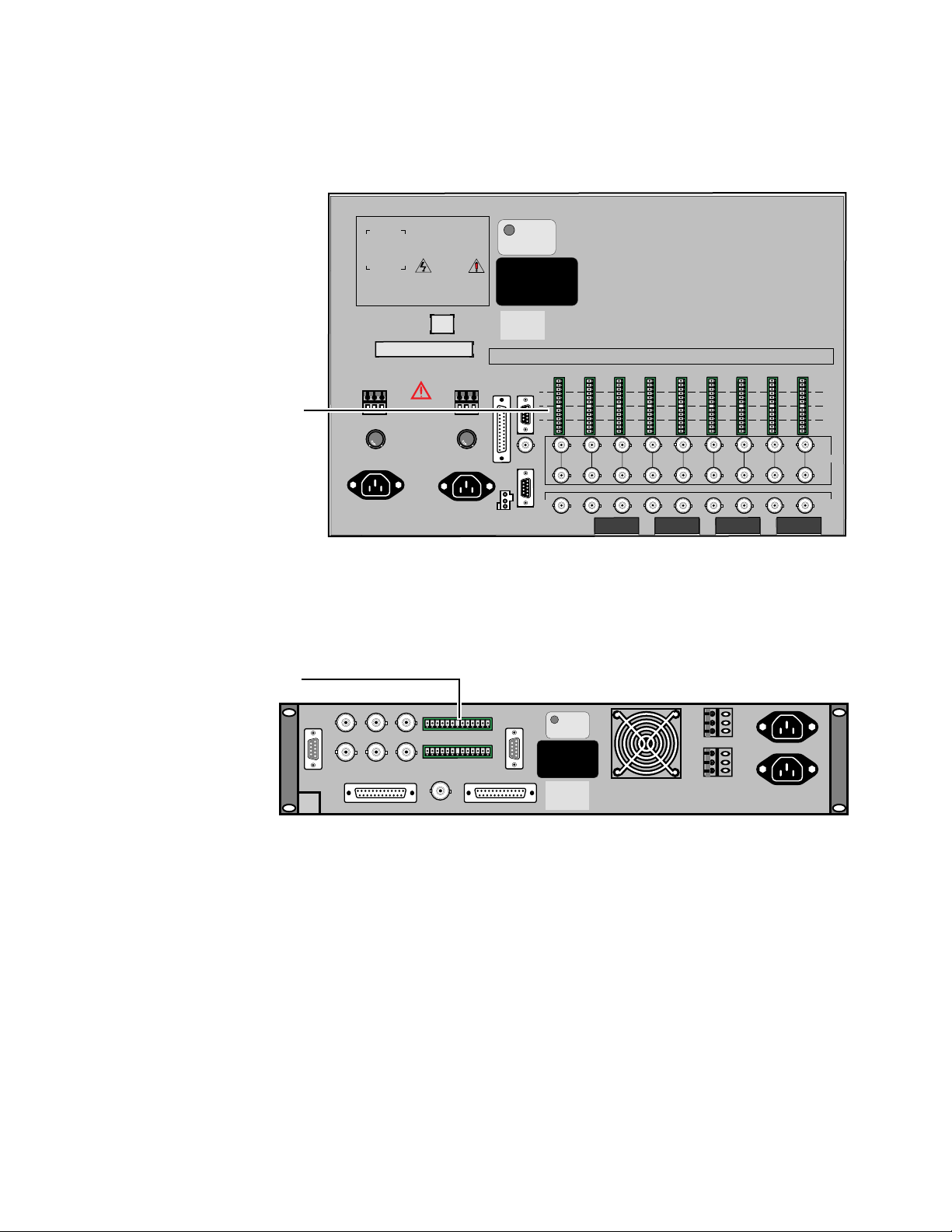
Making Signal Connections
C
D
B
AA
B
D
CC
D
B
AA
B
D
CC
D
B
A
SLOT
USE
SLOT
USE
98
AUD/VIDAUD/VID
7
AUD/VID DATA
6
AUD/VID
54
AUD/VID AUD/VID
3
AUD/VID
2
AUD/VID
0
FIBER1AUD/VID
48VDC
FAN
POWER
J5
RS232
CRAFT
PORT
J04
PORT
ADMIN.
RS232
RS485/
J02
AUDIO/AUDIO/AUDIO/AUDIO/
DATA DATA DATA DATA
AUDIO/
+
-
DATA
-
+
GND
GND
GND
-
+
-
+
GND
AUDIO/
-
+
GND
-
GND
+
GND
DATA
+
-
+
-
GND
AUDIO/
-
+
GND
-
GND
+
GND
DATA
+
-
+
-
GND
AUDIO/
-
+
GND
-
GND
+
GND
DATA
+
-
+
-
GND
-
+
GND
-
GND
+
-
+
GND
+
-
GND
DATA
AUDIO/
I/O
EXP
VIDEO
I/O
IN 1
J03
GND
——+
120/240 VAC
120/240 VAC
Leitungen entfernen.
beide Netzanschlu
§ -
Zur Trennung vom Netz
CORDS BEFORE SERVICING.
SHOCK, DISCONNECT BOTH POWER
TO REDUCE THE RISK OF ELECTRIC
THIS UNIT HAS TWO POWER CORDS.
IF EQUIPPED WITH REDUNDANT POWER
WARNING
48VDC
GND
—+
J01
ALARM
J11
J12
J13
J21
J22
J23
J31
J32
J33
J41
J42
J43
IN 2
IN 3
IN 4
J51
J52
IN 5
J61
J62
IN 6
J71
J72
IN 7
J81
J82
IN 8
J91
J92
IN 9
J53
J63
J73
J83 J93
VIDEO
IN
VIDEO
IN
VIDEO
I/O
I/O 1 I/O 2 I/O 3 I/O 4 I/O 5 I/O 6 I/O 7 I/O 8 I/O 9
J2
S2
J4
J1
S1
J3
WARNING
GRASS VALLEY GROUP, INC.
MODEL: MCF SERIES
MADE IN U.S.A.
VERIFY VOLTAGE SETTING
BEFORE APPLYING POWER
Vor Anschlu§ on das Netz
Aufstellanitung beachten!
RATED VOLTAGE: 100-120VAC~/200-240VAC~/ 48VDC
RATED CURRENT: 6 A MAX / 3 A MAX / 12 A MAX
FREQUENCY: 50-60Hz 50-60Hz
DATE OF
MFG
110 220
110 220
THIS DEVICE COMPLIES WITH PART
15 OF THE FCC RULES OPERATION
SUBJECT TO THE FOLLOWING TWO
CONDITIONS: (1) THIS DEVICE MAY
NOT CAUSE HARMFUL INTERFERENCE
(2) THIS DEVICE MUST ACCEPT ANY
INTERFERENCE RECEIVED INCLUDING
INTERFERENCE THAT MAY CAUSE
UNDESIRED OPERATIONS.
ETL LISTED
TELEPHONE
EQUIPMENT
Conforms to ULSTD 1459
ETL TESTING LABORATORIES, INC.
CORTLAND, NEW YORK, 13045
E
L
T
CAUTION:
This unit has more than one power source.
Disconnecting power cords
may not de-energize unit.
ATTENTION:
Ca produit a plus qu’une Source de pouvior
electrique. Debranchement n’ assure pas
de-energisation de I’ equipement.
5158-99
Audio
Connectors
See Figure 2-30 for location of the audio connectors on the 6 RU frame backplane.
Figure 2-30. Backplane Audio Connections for the 6 RU Frame
See Figure 2-31 for location of the audio connectors on the 2 RU frame
backplane.
Audio
Connectors
J2 J3
J1
J10
J4
J5
J6
J11
J8
J13
J9
J7
J12
ETL LISTED
E
L
TELEPHONE
T
EQUIPMENT
Conforms to ULSTD 1459
ETL TESTING LABORATORIES, INC.
CORTLAND, NEW YORK, 13045
THIS DEVICE COMPLIES WITH PART
15 OF THE FCC RULES OPERATION
SUBJECT TO THE FOLLOWING TWO
CONDITIONS: (1) THIS DEVICE MAY
NOT CAUSE HARMFUL INTERFERENCE
(2) THIS DEVICE MUST ACCEPT ANY
INTERFERENCE RECEIVED INCLUDING
INTERFERENCE THAT MAY CAUSE
UNDESIRED OPERATIONS.
CAUTION:
This unit has more than one power source.
Disconnecting power cords
may not de-energize unit.
ATTENTION:
Ca produit a plus qu'une Source de pouvior
electrique. Debranchement n' assure pas
de-energisation de I' equipement.
Figure 2-31. Backplane Audio Connections for the 2 RU Frame
CAUTION Do not use Channels B or D with Serial Digital audio connections. Use Channel
MCF Installation and Service 2-37
make these connections, refer to Figures 2-30 and 2-31 (for connector locations). See Figure 2-32 and perform the following steps:
1. Strip the connecting ends of the shielded twisted pair of audio leads
2. With a small screwdriver, loosen the screws in the connector.
A on the audio connector for audio channels 1/2. Use Channel C for audio
channels 3/4.
enough for easy insertion into the connector.
Figure 2-31 illustrates the method of making the audio connections. To
GND
+
GND
–
+
–
5158-98
Page 82

Section 2 — Installation
Audio Connector Orientation for the 6 RU Frame
3. Starting with the desired channel leads, insert them one at a time into
the connector slots and tighten each screw.
4. When all audio leads have been attached, and while observing the slot
location(s) of the Audio modules, press the connector onto the MCF
frame connector pins. Note that the connectors are keyed to prevent an
error, and that once the connectors are seated, removing them is
difficult.
Note that in the 6 RU frame, the three Channel A connections are at the top
of the connector and the three Channel D connections are at the bottom,
with orientation as follows: Ground, Low (–), and High (+) for each
channel. See Figure 2-32
5139-13
Ground
Low (-)
High (+)
A
B
C
D
Figure 2-32. Making Audio Connections (6 RU frame)
Audio Connector Orientation for the 2 RU Frame
Note that in the 2 RU frame, the three Channel A connections are at the far
right on the connector and the three Channel D connections are at left, with
orientation as follows from right to left: Ground, Low (–), and High (+) for
each channel. See Figure 2-33.
2-38 MCF Installation and Service
Page 83

Ground
Low (–)
High (+)
Making Signal Connections
5139-13a
Figure 2-33. Making Audio Connections (2 RU frame)
Audio Clip Level
Each MCF system has user-selectable Audio Input and Output signal
levels. These levels are adjusted by turning the gain adjustment potentiometer and viewing the Clip and Quiet LED indicators located on the front of
the modules.
The LED indicators at the front of the Audio Input and/or Output module
signify excessive input or output signal levels that result in signal distortion. If a clip indicator is illuminated only occasionally or momentarily, no
action is required. If clipping is continuous, the input/output signal should
be attenuated or the gain reduced. If the desired headroom is +16 dB, the
desired clip level calculation would be as follows:
CD
AB
Nominal Input = + 8 dBm
Desired Headroom = +16 dB
Clip Level Setting = +24 dBm
MCF Installation and Service 2-39
Page 84

Section 2 — Installation
Set the front panel clip level by rotating the switches located on the front of
the module. See Figure 2-34. Refer to page 2-63, for more detailed information about setting clip levels.
5143-202
CLIP LEVEL
(dBm)
+16
+20
+24
A/B
+16
+20
+24
C/D
+12
+8
+12
+8
These two controls (one
for the A/B stereo pair
and one for the C/D stereo
pair) are used to adjust the
clip level for the stereo
pair. Adjustment is from
+8 dBm to +24 dBm in
increments of 4 dBm.
Figure 2-34. Audio Input/Output Clip Adjustment
Fiber-Optic Connection
Before making the fiber-optic connection, ensure that the cable end and termination are clean. Use of a precision-spray duster is recommended. (A
typical product is Miller-Stephenson Aero-Duster, part number MS-220.)
To make the connection:
1. Carefully push the cable connector into the connector on the Fiber
module.
2-40 MCF Installation and Service
Page 85

Fiber Module Settings
2. Hand-tighten the cable nut to the Fiber module connector. See
Figure 2-35.
5143-206
Figure 2-35. Fiber-Optic FC/PC Connector
If you wish to install optical attenuators in your system, follow the installation instructions sent with the attenuator connectors. Refer to Section 5,
Table 5-2 for specific attenuator connector model numbers.
Figure 2-36 shows the three types of fiber connectors available with the
MCF system—FC, ST, and SC.
FC
Figure 2-36. Fiber-Optic FC, ST, and SC Connectors
Fiber Module Settings
■ The Fiber Receiver and Transmitter modules have two DIP switches
that must be set:
■ Craft Port Parity and Baud Rate Selection
ST
SC
■ Transmitter or Receiver Frame Address ID
Jumper 401 (mode) at the top of the Fiber Receiver module is not userselectable. It should always be set across pins 1–6 (which is the factory
default) for the module to work correctly.
MCF Installation and Service 2-41
Page 86

Section 2 — Installation
Craft Port Parity and Baud Rate
The following text describes how to set up the two DIP switches.
Craft port configuration is accomplished by setting its baud rate and parity
through DIP switch S2 on the Fiber Transmitter and Receiver modules. The
DIP switch location on both Fiber modules is illustrated in Figure 2-37.
Craft Port Baud
Rate & Parity
Switch
Figure 2-37. Craft Port Baud Rate and Parity DIP Switch on Either Fiber Module
Both the baud rate and parity are set on the Fiber Transmitter or Receiver
module using the 8-segment DIP switch S2, where segments 1, 2, and 3 are
used for baud rate selection and segment 4 is used for parity.
Figure 2-38 illustrates DIP switch S2 with all possible baud rates and the
positions of the switch segments. Table 2-7 on page 2-43 lists the positions
of S2 with the various baud rates available.
Note that 9600 baud is selectable with segments 1, 2, and 3 all set to Open
(Off) or all set to Closed (On).
S1 ADDRESS
O
1
N
2
3
4
5
6
7
8
S2 BAUD RATE & PARITY
O
1
N
2
3
4
5
6
7
8
TP5158-204
2-42 MCF Installation and Service
Page 87

Fiber Module Settings
To set Parity, DIP switch S2, segment 4 is Closed (On) for no Parity and
Open (Off) for odd Parity.
Open
Baud Baud
Parity
Baud Rate = 19,200
Open
Parity
Baud Rate = 2400
Closed
ON
1
2
3
4
5
6
7
8
Closed Open
ON
1
2
3
4
5
6
7
8
Open
1
2
3
4
Parity
5
6
7
8
Baud Rate = 9600
Closed Open
ON
1
2
3
4
Parity
5
6
7
8
Baud Rate = 1200
Closed
ON
Open
1
2
3
4
or
5
6
7
8
Parity
Figure 2-38. Baud Rate and Parity Selection Switch, S2
Table 2-7. Baud Rate Selection, S2
Baud Rate Position 1 Position 2 Position 3
19,200 Closed Open Open
9600 Open Open Open
9600 Closed Closed Closed
4800 Open Closed Closed
2400 Closed Open Closed
1200 Open Open Closed
600 Closed Closed Open
300 Open Closed Open
Closed
ON
Baud
Parity
Closed Open
ON
1
2
3
4
5
6
7
8
Baud Rate = 600
Open
1
2
Baud
3
4
Parity
5
6
7
8
Baud Rate = 4800
1
2
BaudBaudBaudBaud
3
4
Parity
5
6
7
8
Baud Rate = 300
Closed
ON
Closed
ON
TP5158-205
MCF Installation and Service 2-43
Page 88

Section 2 — Installation
Transmitter or Receiver Frame Address
Each MCF frame must have a unique address assigned from 0 (zero) to 255.
This frame identifier is set on the Fiber Transmitter and Receiver modules.
Switch S1 is an 8-position DIP switch used to set the address for the MCF
frame within which the Fiber module resides. Figure 2-39 illustrates the
location of S1 on the Transmitter or Receiver module.
Transmitter or Receiver
Frame Address Switch
Figure 2-39. Frame Address DIP Switch
Each segment of the DIP switch has a numeric (binary) value. The left side
of Figure 2-40 illustrates the numeric value for each segment on the DIP
switch, and the right side illustrates an example of a specific address. In the
example shown, frame address 83 is selected. Selections are made by
setting the desired switch segment to the appropriate Closed (On) or Open
(Off) position. So, you may assign any address number (between zero and
255) by turning on or off different binary switch combinations.
Value with
switch off
S1 ADDRESS
O
1
N
2
3
4
5
6
7
8
Value with
switch on
S1
1
0
2
0
3
0
4
0
5
0
6
0
7
0
8
0
ON
16
32
64
+128
255
S2 BAUD RATE & PARITY
1
2
3
4
5
6
7
8
1
2
4
8
O
N
Example if desired
address is 83
TP5158-209
S1
1
2
3
4
5
6
7
8
ON
1
2
—
—
16
—
64
+ —
83
Figure 2-40. Address DIP Switch, S1
2-44 MCF Installation and Service
Page 89
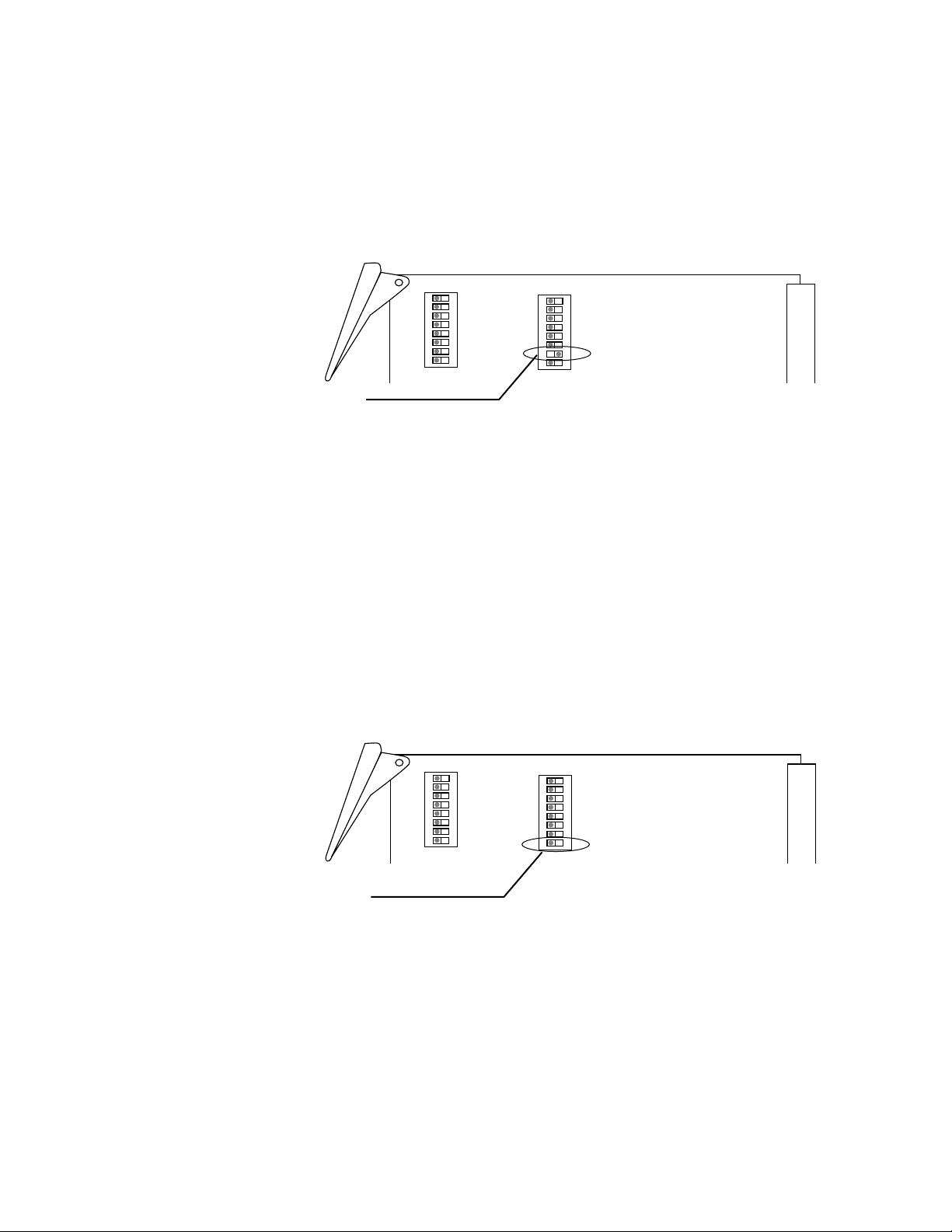
Slave Function (Transmitter Module only)
Segment 7 on DIP Switch 2 (S2) on the enhanced Transmitter module
allows the Transmitter to operate as a slaved Transmitter in the Repeater
frame. This segment must be in the ON position for the Repeater operation
to function. Refer to Figure 2-41 for the DIP switch location.
Fiber Module Settings
S1 ADDRESS
O
1
N
2
3
4
5
6
7
8
S2 BAUD RATE & PARITY
O
1
N
2
3
4
5
6
7
8
Slaved Transmitter
Switch Location
Figure 2-41. Slaved Transmitter Switch Location, S2
Boot Function (Transmitter/Receiver Module)
Segment 8 on DIP Switch 2 (S2) on both fiber modules allows the software
to start up in boot mode. This allows you to upload new operational software from a PC to the FLASH ROM on the Transmitter or Receiver module.
The segment’s normal operational position is in the OFF or disabled position. This allows the software to start up in the normal operation mode.
Refer to Figure 2-42 for the DIP switch locations on both the Transmitter
and Receiver modules.
Note Most commands are disabled when operating in the boot mode.
S1 ADDRESS
O
1
N
2
3
4
5
6
7
8
S2 BAUD RATE & PARITY
O
1
N
2
3
4
5
6
7
8
Transmitter or Receiver
Figure 2-42. Boot Function Switch Location, S2
MCF Installation and Service 2-45
Page 90

Section 2 — Installation
Video Input and Output Module Settings
Various jumper selections on the Video Input and Output modules are
required for proper system operation:
■ Cable Equalization Selection
■ External or Internal Video Termination (75 Ohm)
■ Video Signal Squelch
■ DC Restore
The following text describes how to select these settings.
Cable Equalization
A Video module may need cable equalization to compensate for cable
length. Each Video module has an equalization (EQ) potentiometer on the
front panel which may be adjusted for this compensation. Adjustment preequalizes from an Output module or equalizes from an Input module. Measurement is taken with a waveform monitor at the front panel MONITOR
connector for a Video Input module and at the backplane VIDEO I/O connector for a Video Output module.
The EQ potentiometer is enabled/disabled by a jumper at either J10 (on a
Video Input module) or J14 (on a Video Output module). See Figures 2-43
and 2-44 for jumper locations on the modules. If equalization is flat (no
equalization necessary), EQ is disabled by installing the jumper block
across positions one and two. This setting is the factory default. To enable
EQ, install the jumper block across positions two and three.
If cable equalization is required, it will be necessary to install one or two
Hybrid Equalization boards, depending on the cable length, and to change
and/or add a jumper block on the affected module. Hybrid Equalization
modules must be ordered separately, as needed. See Table 2-8 on page 2-47.
Video Input Module Cable Equalization
Cable equalization is attained by installing the Hybrid boards U29 and U37
and setting up the jumper block at J9 on the Video Input module. Cable
length determines whether one or two Hybrid boards need to be installed
and also determines the position of the jumper block. Lengths of 0–500 feet
require one board and lengths of 500–1000 feet require both Hybrid boards.
In addition, the Hybrid boards are video cable I.D. specific. See Table 2-8 on
page 2-47 for specific cable model numbers.
For a Video Input module, Figure 2-43 illustrates the locations of the EQ
jumper J10, the Hybrid board plug-ins, and the Hybrid boards’ jumper, J9.
Table 2-8 on page 2-47 lists the Hybrid boards by cable I.D. for U 37 (0–500
feet) and U 29 (500–1000 feet).
2-46 MCF Installation and Service
Page 91
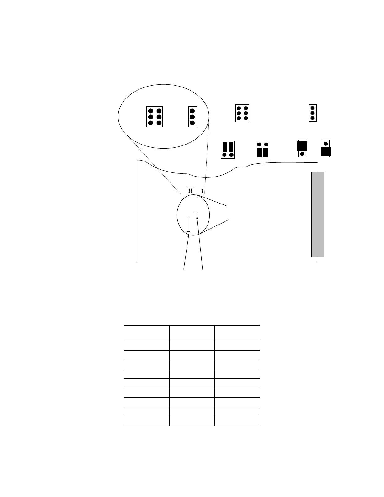
Video Input and Output Module Settings
The procedure for installation of the Hybrids and jumper blocks follows.
Figure 2-44 and the table titled Video Input Cable Equalization Hybrids on
page 2-47.
0 - 500
EQ
500-1000
J9 J10
FLAT
J10
U29EQ
J9
0 - 500
EQ
500-1000
U37
U29 EQ
J9 Pin
Orientation
1
2
3
0 - 500
FLAT
J10
Hybrid Equalization
Board Plug Ins
6
5
4
500 - 1000
J10 Pin
Orientation
1
2
3
Flat EQ
1
2
3
1
2
3
U37 U29
Figure 2-43. Video (only) Input Module Cable Equalization
Table 2-8. Video Input Cable Equalization Hybrids
Cable I.D.
0 - 500 feet
(qty = 1)
500 - 1000 feet
(qty = 2)
8281 HB9054-00 HB9055-00
RG59B/U HB9057-00 HB9058-00
9259 HB9062-01 HB9062-02
8238 HB9062-04 HB9062-05
CHESTER 23 HB9062-09 HB9062-10
AF 0.8/3.7 HB9062-11 HB9062-12
PSF 1/3 HB9062-13 HB9062-14
F & G 0.6/3/7 HB9062-15 HB9062-16
F & G 1.0/6.6 HB9054-10 HB9055-10
MCF Installation and Service 2-47
Page 92

Section 2 — Installation
Video Output Module Cable Equalization
Cable equalization is attained by installing the Hybrid boards U28 and U29
and setting up the jumper block at J12 on the Video Output module. Cable
length determines whether one or two Hybrid boards need to be installed
and also determines the position of the jumper block. Lengths of 0–500 feet
require one board and lengths of 500–1000 feet require both Hybrid boards.
In addition, the Hybrid boards are video cable I.D. specific. See Table 2-10
on page 2-66 for specific model numbers.
For a Video Output module, Figure 2-44 illustrates the locations of the EQ
jumper J14, the Hybrid board plug ins, and the Hybrid boards’ jumper, J12.
Table 2-10 on page 2-66 lists the Hybrid boards by cable I.D for U28 (0–500
feet only) and U29 (500–1000 feet).
A procedure for installation of Hybrids and jumper blocks follows
Figure 2-44 and Table 2-10 on page 2-66.
0-500
500
J12
EQ
1000
U28
U29
J12 Pin
Orientation
1
2
3
0 - 500
0 - 500
J12
EQ
1000
500
6
5
4
500 - 1000
FLAT
J14
EQ
J14
J14 Pin
Orientation
1
2
3
Flat EQ
1
2
3
1
2
3
U28 U29
Figure 2-44. Video (only) Output Module Cable Equalization
2-48 MCF Installation and Service
Page 93

Installation of Hybrid Boards
5143-207
0-500
500-1000
J12
U29U28
J14
FLAT
EQ
GRASS VALLEY GRO
VIDEO OUTPUT
066035–
Hybrid Pin 1
Location
Front of Video
Output Module
Rear
Connector
For the following procedure, refer to Figure 2-43 and Table 2-8 on page 2-47
for a Video Input module and to Figure 2-44 and Table 2-10 on page 2-66
for a Video Output module. Install equalization Hybrid boards and jumper
blocks per the following steps:
CAUTION This equipment contains static sensitive components. Use anti-static
grounding equipment whenever handling modules and components. When
circuit modules are removed from the frame, place them on a flat static-controlled surface. Failure to follow this precaution can result in component
damage due to electrostatic discharge.
1. Remove the appropriate Video Input/Output module and place on a
flat, level, static-free surface with the orientation as shown in either
Figure 2-43 or 2-44.
2. To enable the EQ potentiometer on either J10 (for the input module) or
J14 (for the Output module), move the jumper from pins 1 and 2 and
place it over pins 2 and 3. (See either Figure 2-43 or 2-44.) If no Hybrid
is to be installed, skip to Step 5. Otherwise, proceed with Step 3.
Video Input and Output Module Settings
3. Install the Hybrid(s) appropriate to the Video I/O module and cable
type. (See the tables and figures in previous text for correct Hybrid
location and Hybrid part number.) Note that the Hybrid board is
installed with Pin 1 toward the top of the module as illustrated in
Figure 2-45.
Figure 2-45. Video Output Hybrid Pin Orientation
MCF Installation and Service 2-49
Page 94

Section 2 — Installation
4. Install/move the jumper block at either J9 or J12 to the appropriate
position for either 0–500 feet of cable length or 500–1000 feet cable
length as shown in Figure 2-46 below.
0 - 500
EQ
500-1000
Figure 2-46. Jumper Block Orientation
Video Signal Termination
To preserve the shape and integrity of a video waveform traveling along a
cable, the cable must be terminated in an impedance equal to its characteristic impedance. In the MCF system, the physical ends of the video cable
must be terminated with a 75 Ohm resistor. Leaving off the terminations
generally results in poor video signal operation. If loop-through video
operation is desired, termination is not required.
Video Squelch Jumper
When no video signal is present, the MCF Receiver module outputs a high
level of unquieted noise. Because this is not desirable, squelch circuitry can
blank the video output. Refer to Figure 2-47 for the location of the video
J9
J9
5143-204
0 - 500
EQ
500-1000
2-50 MCF Installation and Service
Page 95

Video Input and Output Module Settings
ON
OFF
5158-203
J10
1
2
3
ON
OFF
J10
Squelch
SQUELCH
1
2
3
squelch jumper J10 on the Video Output module. The default setting is
Video Output squelch disabled. Note that there is no Video Squelch jumper
on the Video Input module.
Figure 2-47. Video Output Squelch Jumper
DC Restore Jumper
The MCF system’s DC restoration circuitry provides a slow return of the
base level of the video signal to a fixed DC reference voltage. Due to the
design of DC restore circuitry, rapid corrections of the video signal are not
possible. However, the signal’s DC component is restored without introducing the distortion caused by clamping.
Both the Video Input and Output modules have DC restoration circuitry,
and you must set jumpers on both modules to enable the DC restore operation. See the following text for details.
MCF Installation and Service 2-51
Page 96

Section 2 — Installation
Video Input DC Restore Jumper
When the jumper is set to ON, the MCF system’s DC restoration circuitry
provides a slow return of the video input signal to a fixed DC reference
voltage. Figure 2-48 illustrates the location of jumper J13 on the Video Input
module.
5158-201
J13
OFF
ON
J13
DC
RESTORE
OFF
ON
Figure 2-48. Video Input DC Restore Jumper
Video Output DC Restore Jumper
Likewise, on the Video Output module when jumper J16 is set to ON, the
video output signal is fixed to a DC reference voltage. Figure 2-49 illustrates the location of jumper J16 on the Video Output module.
OFF
J16
DC RESTORE
ON
OFF
J16
DC RESTORE
ON
Figure 2-49. Video Output DC Restore Jumper
5158-202
2-52 MCF Installation and Service
Page 97

Audio Input Module Setting
The Audio Input module has a single jumper setting—audio input attenuation. The following text describes this jumper setting and jumper location.
Input Audio Attenuation
The MCF system is designed with an audio gain of unity into a 600 Ohm
impedance load. However, your facility may require a different setting. The
input impedance may be changed from 600 to 150 Ohm or HIGH Ohm (30
Kowloon differential) impedance (for bridging applications).
To set jumpers J7, J8, J9, and J10 on the Audio Input module, follow the
steps listed below:
1. Remove the Audio Input module from the frame, and place on a flat,
level, static-free surface with the module orientation as shown in
Figure 2-50.
Audio Input Module Setting
2. Select the appropriate impedance jumper settings for Channels A (J7),
B (J8), C (J9), and D (J10).
3. Reinstall the module into the frame and resume operation.
J7
600Ω
150Ω
HIGHΩ
5143-203
J8 J9 J10J7
Figure 2-50. Audio Input Jumper Settings
MCF Installation and Service 2-53
Page 98

Section 2 — Installation
Combined Video/Audio Module Settings
The Combined Video/Audio modules have numerous user-selectable settings:
■ Cable Equalization Selection
■ External or Internal Video Termination (75 Ohm)
■ EQ Adjustment
■ DC Restore Settings (Early Production Boards)
■ Video Clamp Settings (Recent Production Boards)
■ Audio Impedance Settings
■ Audio Attenuation Clip Selections
The following text describes how to select these settings.
Input Cable Equalization
A Video/Audio Input module may need cable equalization (video only) to
compensate for your cable length. Each Video/Audio Input module has an
equalization (EQ) potentiometer on the front panel which may be adjusted
for this compensation. The adjustment equalizes the video input. Measurements are taken with a waveform monitor at the front panel MONITOR
connector.
2-54 MCF Installation and Service
Page 99

Combined Video/Audio Module Settings
The EQ circuit is enabled/disabled by jumper J14 (on the Input module).
See Figure 2-51 for the location of J14 on the module.
J21
Cable Length
500 to 1000 Ft
J14 EQ
Disabled
1
2
3
J14
J14 EQ
Enabled
1
2
3
J21
Cable Length
0 to 500 Ft
Pin
Orientation
J14
1
2
3
EQ Hybrid
Board Locations
U61
U65
Figure 2-51. Combined Video/Audio Input Module Video Cable Equalization Jumper Location
EQ 0-500
500-1000
J21
J21
1
2
3
6
5
4
The EQ circuit is disabled by installing the jumper block across positions
one and two of jumper J14. This setting is the factory default. EQ is enabled
when you install the jumper block across pins 2 and 3.
5171-215
If cable equalization is required, it will be necessary to install one or two
Hybrid Equalization boards (depending on the length) and to change and/
or add a jumper block on the Input module.
Cable equalization is attained by installing the Hybrid boards, U61 (0-500
feet) or U65 (500-1000 feet) and by setting up the jumper block at J21. Refer
to Figure 2-51 for the equalization hybrid board plug-ins and jumpers J14
and J21 locations.
Whether one or two Hybrid boards need to be installed and the position of
the jumper block depends on the cable length. Lengths of 0–500 feet require
one board and lengths of 500–1000 feet require both Hybrid boards. In
addition, the Hybrid boards are video cable I.D. specific by length.
Table 2-8 on page 2-47 gives specific cable model numbers.
MCF Installation and Service 2-55
Page 100
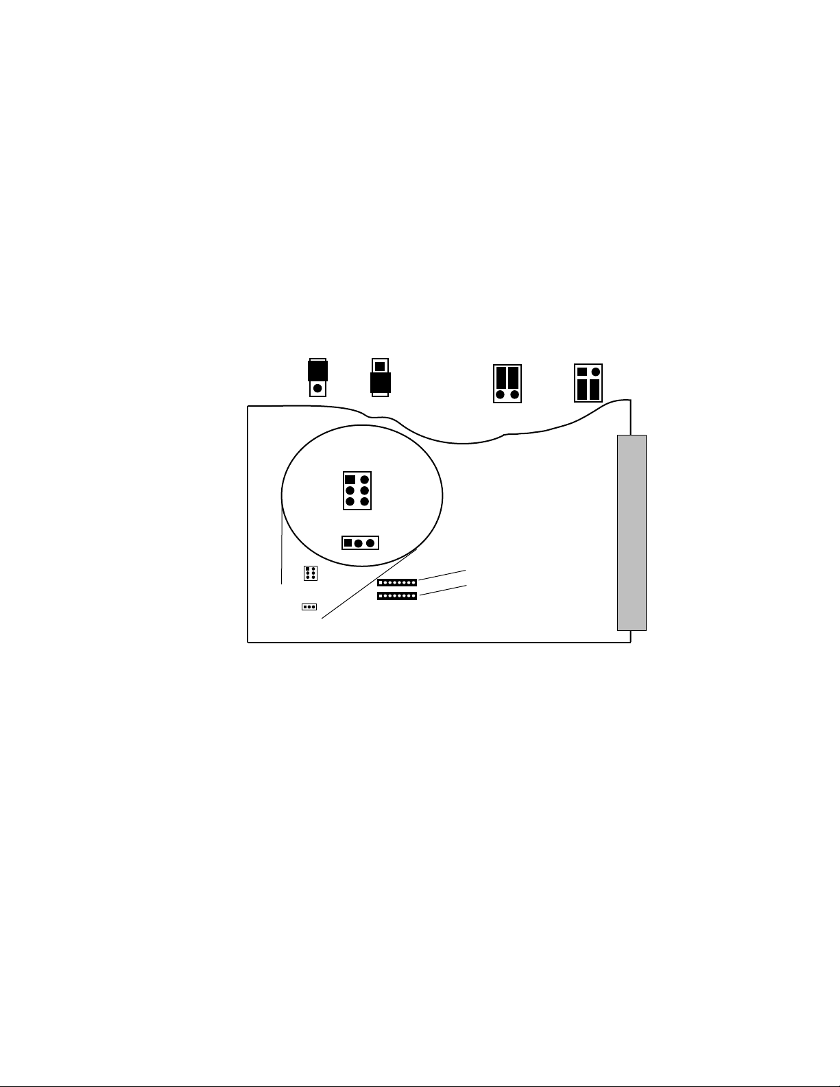
Section 2 — Installation
Output Cable Equalization
A Video/Audio Output module may need cable pre-equalization (video
only) to compensate for your cable length. Each Video/Audio Output
module has an equalization (EQ) potentiometer on the front panel which
may be adjusted for this compensation. The adjustment pre-equalizes the
video output. Measurements are taken with a waveform monitor at the
backplane VIDEO I/O connector.
The EQ circuit is enabled/disabled by jumper J17 (on the Video/Audio
Output module). See Figure 2-52 for the jumpers J15 and J17 locations.
J17 EQ
Disabled
1
2
3
J15
EQ 0-500
500-1000
J17 EQ
Enabled
1
2
3
Pin
Orientation
J15
1
2
3
6
5
4
1
3 2
J17
J15
Cable Length
0 to 500 Ft
EQ Hybrid
Board Locations
U51
J15
Cable Length
500 to 1000 Ft
5171-216
U54
J17
Figure 2-52. Combined Video/Audio Output Module Video Cable Equalization Jumper Location
The EQ circuits are disabled by installing the jumper block across positions
one and two of jumper J17. This setting is the factory default. EQ is enabled
when you install the jumper block across positions two and three.
If cable pre-equalization is required, it will be necessary to install one or
two Hybrid Equalization boards (depending on the length) and to change
and/or add a jumper block on the Output module.
Cable equalization is attained by installing the Hybrid boards, U51 (5001000 feet) or U54 (0-500 feet), and setting up the jumper block at J15. Refer
to Figure 2-52 for the equalization hybrid board plug-ins and jumpers J15
and J17 locations.
2-56 MCF Installation and Service
 Loading...