


Software
Model 5000
Software Developer’ s Guide V1.1
81840 Rev. B / 6-98

WARRANTY
Hardware
Keithley Instruments, Inc. warrants that, for a period of one (1) year from the date of shipment (3 years for Models 2000, 2001, 2002, and 2010), the Keithley
Hardware product will be free from defects in materials or workmanship. This warranty will be honored provided the defect has not been caused by use of the
Keithley Hardware not in accordance with the instructions for the product. This warranty shall be null and void upon: (1) any modification of Keithley Hardware that is made by other than Keithley and not approved in writing by Keithley or (2) operation of the Keithley Hardware outside of the environmental specifications therefore.
Upon receiving notification of a defect in the Keithley Hardware during the warranty period, Keithley will, at its option, either repair or replace such Keithley
Hardware. During the first ninety days of the warranty period, Keithley will, at its option, supply the necessary on site labor to return the product to the condition prior to the notification of a defect. Failure to notify Keithley of a defect during the warranty shall relieve Keithley of its obligations and liabilities under
this warranty.
Other Hardware
The portion of the product that is not manufactured by Keithley (Other Hardware) shall not be covered by this w arranty, and Keithley shall have no duty of obligation to enforce any manufacturers' warranties on behalf of the customer. On those other manufacturers’ products that Keithley purchases for resale, Keithley
shall have no duty of obligation to enforce any manufacturers’ warranties on behalf of the customer.
Software
Keithley warrants that for a period of one (1) year from date of shipment, the Keithle y produced portion of the software or firmw are (Keithley Software) will conform in all material respects with the published specifications provided such Keithley Software is used on the product for which it is intended and otherwise in
accordance with the instructions therefore. Keithley does not warrant that operation of the Keithley Softw are will be uninterrupted or error-free and/or that the
Keithley Software will be adequate for the customer's intended application and/or use. This warranty shall be null and v oid upon an y modification of the K eithle y
Software that is made by other than Keithley and not approved in writing by Keithley.
If Keithley receiv es notification of a K eithle y Software nonconformity that is co v ered by this warranty during the w arranty period, K eithle y will review the conditions described in such notice. Such notice must state the published specification(s) to which the Keithley Software fails to conform and the manner in which
the Keithley Software fails to conform to such published specification(s) with sufficient specificity to permit K eithle y to correct such nonconformity. If Keithley
determines that the Keithley Software does not conform with the published specifications, Keithley will, at its option, provide either the programming services
necessary to correct such nonconformity or develop a program change to bypass such nonconformity in the Keithley Software. Failure to notify Keithley of a
nonconformity during the warranty shall relieve Keithley of its obligations and liabilities under this warranty.
Other Software
OEM software that is not produced by Keithley (Other Software) shall not be covered by this w arranty, and Keithley shall have no duty or obligation to enforce
any OEM's warranties on behalf of the customer.
Other Items
Keithley warrants the following items for 90 days from the date of shipment: probes, cables, rechar geable batteries, diskettes, and documentation.
Items not Covered under Warranty
This warranty does not apply to fuses, non-rechargeable batteries, damage from battery leakage, or problems arising from normal wear or failure to follow
instructions.
Limitation of Warranty
This warranty does not apply to defects resulting from product modification made by Purchaser without Keithley's express written consent, or by misuse of any
product or part.
Disclaimer of Warranties
EXCEPT FOR THE EXPRESS WARRANTIES ABOVE KEITHLEY DISCLAIMS ALL OTHER WARRANTIES, EXPRESS OR IMPLIED, INCLUDING
WITHOUT LIMIT ATION, ALL IMPLIED WARRANTIES OF MERCHANTABILITY AND FITNESS FOR A PARTICULAR PURPOSE. KEITHLEY DISCLAIMS ALL WARRANTIES WITH RESPECT TO THE OTHER HARDWARE AND OTHER SOFTWARE.
Limitation of Liability
KEITHLEY INSTRUMENTS SHALL IN NO EVENT, REGARDLESS OF CAUSE, ASSUME RESPONSIBILITY FOR OR BE LIABLE FOR: (1) ECONOMICAL, INCIDENTAL, CONSEQUENTIAL, INDIRECT, SPECIAL, PUNITIVE OR EXEMPLARY DAMAGES, WHETHER CLAIMED UNDER
CONTRACT, TORT OR ANY OTHER LEGAL THEORY, (2) LOSS OF OR DAMAGE TO THE CUSTOMER'S DATA OR PROGRAMMING, OR (3) PENAL TIES OR PENALTY CLAUSES OF ANY DESCRIPTION OR INDEMNIFICA TION OF THE CUST OMER OR OTHERS FOR COSTS, DAMAGES, OR
EXPENSES RELATED TO THE GOODS OR SERVICES PROVIDED UNDER THIS WARRANTY.
Keithley Instruments, Inc. • 28775 Aurora Road • Cleveland, OH 44139 • 440-248-0400 • Fax: 440-248-6168 • http://www.keithley.com
CHINA: Keithley Instruments China • Yuan Chen Xin Building, Room 705 • 12 Yumin Road, Dewai, Madian • Beijing 100029 • 8610-62022886 • Fax: 8610-62022892
FRANCE: Keithley Instruments SARL • BP 60 • 3 Allée des Garays • 91122 Palaiseau Cédex • 33-1-60-11-51-55 • Fax: 33-1-60-11-77-26
GERMANY: Keithley Instruments GmbH • Landsberger Strasse 65 • D-82110 Germering, Munich • 49-89-8493070 • Fax: 49-89-84930759
GREAT BRITAIN: Keithley Instruments, Ltd. • The Minster • 58 Portman Road • Reading, Berkshire RG30 1EA • 44-1189-596469 • Fax: 44-1189-575666
ITALY: Keithley Instruments SRL • Viale S. Gimignano 38 • 20146 Milano • 39-2-48303008 • Fax: 39-2-48302274
NETHERLANDS: Keithley Instruments BV • Avelingen West 49 • 4202 MS Gorinchem • 31-(0)183-635333 • Fax: 31-(0)183-630821
SWITZERLAND: Keithley Instruments SA • Kriesbachstrasse 4 • 8600 Dübendorf • 41-1-8219444 • Fax: 41-1-8203081
TAIWAN: Keithley Instruments Taiwan • 1FL., 85 Po Ai Street • Hsinchu, Taiwan • 886-3-572-9077 • Fax: 886-3-572-9031

Model 5000
Software Developer’s Guide
©1998, Keithley Instruments, Inc.
All rights reserved.
Cleveland, Ohio, U.S.A.
First Printing, June 1998
Document Number: 81840 Rev. B

Manual Print History
The print history shown below lists the printing dates of all Revisions and Addenda created for this manual. The Revision
Level letter increases alphabetically as the manual undergoes subsequent updates. Addenda, which are released between Revisions, contain important change information that the user should incorporate immediately into the manual. Addenda are numbered sequentially. When a new Revision is created, all Addenda associated with the previous Revision of the manual are
incorporated into the new Revision of the manual. Each new Revision includes a revised copy of this print history page.
Revision A (Document Number 81840)...............................................................................................August 1996
Revision B (Document Number 81840)................................................................................................... June 1998
All Keithley product names are trademarks or registered trademarks of Keithley Instruments, Inc.
Other brand and product names are trademarks or registered trademarks of their respective holders.

About this manual
Quality control
Keithley Instruments manufactures quality and versatile products, and we want our documentation to reflect that same quality. We take great pains to publish manuals that are informative and
well organized. We also strive to make our documentation easy to understand for the novice as
well as the expert.
If you have comments or suggestions about how to mak e this (or other) manuals easier to understand, or if you find an error or an omission, please fill out and mail the reader response card at
the end of this manual (postage is prepaid).
Conventions
Procedural
Keithley Instruments uses various conventions throughout this manual. You should become
familiar with these conventions as they are used to draw attention to items of importance and
items that will generally assist you in understanding a particular area.
WARNING
CAUTION
NOTE
When referring to pin numbering, pin 1 is always associated with a square solder pad on the
actual component footprint.
A warning is used to indicate that an action must be done with great
care. Otherwise, personal injury may result.
A caution is used to indicate that an action may cause minor equipment damage or the loss of data if not performed carefully.
A note is used to indicate important information needed to perform an
action or information that is nice-to-know.
Notational
A forward slash (/) preceding a signal name denotes an active LOW signal. This is a standard
Intel convention.
Caret brackets (<>) denote keystrokes. For instance <Enter> represents carriage-return-withline-feed keystroke, and <Esc> represents an escape keystroke.
Driver routine declarations are shown for C and BASIC (where applicable).
Hungarian notation is used for software parameters. In other words, the parameter type is
denoted by a one or two letter lower case prefix:
c character, signed or unsigned
s short integer, signed
w short integer, unsigned
l long integer, signed
dw long integer, unsigned
For example, wBoardAddr would be an unsigned short integer parameter.

An additional p prefix before the type prefix indicates that the parameter is being passed by reference instead of by value. (A pointer to the variable is being passed instead of the variable
itself).
For example, pwErr would be an unsigned short integer parameter passed by reference.
This notation is also used in BASIC although no distinction between signed and unsigned vari-
ables exists.
In BASIC, all parameters also have a type suffix:
$ character, signed or unsigned
% integer, signed or unsigned
& long integer, signed or unsigned
Routine names are printed in bold font when they appear outside of function declarations, e.g.,
ReadStatus.
Parameter names are printed in italics when they appear outside of function declarations, e.g.
sControls.
Constants are defined with all caps, e.g., ALL_AXES. Underscores {_} must be replaced by
periods {.} for use with BASIC.
Combinational logic and hexadecimal notation is in C convention in many cases. For example,
the hexadecimal number 7Ch is shown as 0x7C.
C relational operators for OR and AND functions — “| |” and “&&” — are used to minimize the
confusion associated with grammar.

Table of Contents
1 Programming Overview
Installing the 5000 software ............................................................................................................................... 1-2
Compiling and linking ....................................................................................................................................... 1-2
Microsoft C or Microsoft QuickC .............................................................................................................. 1-2
Borland or Turbo C/C++ ............................................................................................................................ 1-3
Microsoft QuickBASIC ............................................................................................................................. 1-3
Borland Turbo Pascal ................................................................................................................................. 1-4
Programming fundamentals ............................................................................................................................... 1-4
2 Example Programs
Introduction ........................................................................................................................................................ 2-2
Trapezoidal point-to-point move ........................................................................................................................ 2-2
Move program in C .................................................................................................................................... 2-2
Move program in BASIC ........................................................................................................................... 2-3
Move program in Pascal ............................................................................................................................ 2-4
Velocity mode .................................................................................................................................................... 2-5
Homing ............................................................................................................................................................... 2-6
Reading position ................................................................................................................................................ 2-8
3 Move Parameters
Ranges ................................................................................................................................................................ 3-2
Velocity units ..................................................................................................................................................... 3-2
Acceleration/deceleration units .......................................................................................................................... 3-3
Distance units ..................................................................................................................................................... 3-3
4 Interrupt Handling
Introduction ........................................................................................................................................................ 4-2
Enabling interrupts ..................................................................................................................................... 4-2
Interrupts in C or Pascal ..................................................................................................................................... 4-2
Interrupts in BASIC ........................................................................................................................................... 4-2
General notes on using interrupts ....................................................................................................................... 4-3
i

5 Routine Summary
Introduction ........................................................................................................................................................ 5-2
Initialization and hardware control routines ....................................................................................................... 5-2
Axis command routines ...................................................................................................................................... 5-2
Axis data reporting routines ............................................................................................................................... 5-3
A Driver Routine Descriptions
Notational conventions ...................................................................................................................................... A-3
Acceleration ....................................................................................................................................................... A-3
Load acceleration register .......................................................................................................................... A-3
Clockoff ............................................................................................................................................................. A-4
Disable motor output ................................................................................................................................. A-4
Deceleration ....................................................................................................................................................... A-5
Load deceleration register ......................................................................................................................... A-5
DisableIRQ ........................................................................................................................................................ A-6
Disable IRQ lines ...................................................................................................................................... A-6
Distance ............................................................................................................................................................. A-6
Load distance register ................................................................................................................................ A-6
DownPoint ......................................................................................................................................................... A-7
Load downpoint register ............................................................................................................................ A-7
EnableIRQ ......................................................................................................................................................... A-7
Enable IRQ line ......................................................................................................................................... A-7
InitBoard ............................................................................................................................................................ A-8
Initialize board ........................................................................................................................................... A-8
InitSw ................................................................................................................................................................ A-9
Initialize software ...................................................................................................................................... A-9
InputAlertOff ..................................................................................................................................................... A-9
Disable input interrupt ............................................................................................................................... A-9
InputAlertOn .................................................................................................................................................... A-10
Enable input interrupt .............................................................................................................................. A-10
InterruptHooks ................................................................................................................................................. A-10
Install interrupt hooks .............................................................................................................................. A-10
IOControl ......................................................................................................................................................... A-11
Write I/O control register ........................................................................................................................ A-11
ISBusy ............................................................................................................................................................. A-11
Read busy bit ........................................................................................................................................... A-11
LowVelocity .................................................................................................................................................... A-12
Load start velocity register ...................................................................................................................... A-12
ModeSelect ...................................................................................................................................................... A-12
Load mode select register ........................................................................................................................ A-12
Multiplier ......................................................................................................................................................... A-13
Load multiplier register ........................................................................................................................... A-13
OutputHigh ...................................................................................................................................................... A-14
Set GP output HIGH ................................................................................................................................ A-14
OutputLow ....................................................................................................................................................... A-14
Set GP output LOW ................................................................................................................................. A-14
PulsesLeft ........................................................................................................................................................ A-15
Return distance left .................................................................................................................................. A-15
ReadState ......................................................................................................................................................... A-15
Read state buffer ...................................................................................................................................... A-15
ReadStatus ....................................................................................................................................................... A-16
Read status register .................................................................................................................................. A-16
ii

StartStop .......................................................................................................................................................... A-17
Load start-stop register ............................................................................................................................ A-17
Velocity1 ......................................................................................................................................................... A-18
Load FH1 register ................................................................................................................................... A-18
Velocity2 ......................................................................................................................................................... A-19
Load FH2 register ................................................................................................................................... A-19
WriteReg ......................................................................................................................................................... A-19
Write register ........................................................................................................................................... A-19
Profile Utility
Executing the program ...................................................................................................................................... B-2
Base address .............................................................................................................................................. B-2
Color number ............................................................................................................................................ B-2
Main menu ................................................................................................................................................ B-3
Navigating inside the program .................................................................................................................. B-3
Monitoring axis configuration .................................................................................................................. B-3
Single axis menu ....................................................................................................................................... B-4
Global menu .............................................................................................................................................. B-8
Save file/load file ...................................................................................................................................... B-9
Clock ......................................................................................................................................................... B-9
Register display ....................................................................................................................................... B-10
Exit program ........................................................................................................................................... B-10
C Visual C++ Demonstration Program
Product overview .............................................................................................................................................. C-2
System requirements ......................................................................................................................................... C-2
Installation ......................................................................................................................................................... C-2
Operation ........................................................................................................................................................... C-2
Program architecture ......................................................................................................................................... C-3
D Visual BASIC Demonstration Program
User’s guide ...................................................................................................................................................... D-2
Product overview ...................................................................................................................................... D-2
Installation ................................................................................................................................................. D-2
Operation ................................................................................................................................................... D-3
Menu items ................................................................................................................................................ D-5
Developer’s guide ............................................................................................................................................. D-6
Program architecture ................................................................................................................................. D-6
Program organization ................................................................................................................................ D-7
iii

List of Illustrations
A Driver Routine Descriptions
Figure A-1 State buffer .............................................................................................................................................. A-15
Figure A-2 Status buffer ............................................................................................................................................ A-16
Figure A-3 Command buffer ..................................................................................................................................... A-17
B Profile Utility
Figure B-1 Single axis menu screen ............................................................................................................................ B-3
Figure B-2 Active axis: a menu screen ........................................................................................................................ B-4
Figure B-3 Trapezoidal parameters ............................................................................................................................. B-5
Figure B-4 Status buffer .............................................................................................................................................. B-7
Figure B-5 State buffer ................................................................................................................................................ B-7
Figure B-6 Execute global move menu screen ............................................................................................................ B-8
Figure B-7 Save file/load file ...................................................................................................................................... B-9
C Visual C++ Demonstration Program
Figure C-1 5000 C++ demonstration program main user window .............................................................................. C-3
D Visual BASIC Demonstration Program
Figure D-1 5000 Profiler main user window ............................................................................................................... D-3
Figure D-2 Flow diagram for 5000 Visual BASIC Profiler ........................................................................................ D-6
Figure D-3 Text box value assignments for 5000 Profiler main user window ............................................................ D-7
v

List of Tables
3 Move Parameters
Table 3-1 Permissible velocity and acceleration ranges ............................................................................................. 3-2
5 Routine Summary
Table 5-1 Notational conventions .............................................................................................................................. 5-2
B Profile Utility
Table B-1 PRO5000 color selections ......................................................................................................................... B-2
Table B-2 Selecting a clock speed ............................................................................................................................. B-9
D Visual BASIC Demonstration Program
Table D-1 Physical data fields .................................................................................................................................... D-4
Table D-2 Velocity data fields ................................................................................................................................... D-5
Table D-3 Accel and decel data fields ........................................................................................................................ D-5
Table D-4 Miscellaneous data fields .......................................................................................................................... D-5
Table D-5 Code module descriptions ......................................................................................................................... D-8
Table D-6 Form module descriptions ......................................................................................................................... D-8
vii

1
Programming Overview

1-2 Programming Overview Model 5000 Software Developer’s Guide
Installing the 5000 software
The 5000 driver includes the batch file, INSTALL.BAT, to install the software. The batch file
takes one argument, which is the path where you will install the software. For e xample, to install
the software on the C drive into a subdirectory called 5000, enter on the command line:
install c:000
Use the same path for the installation of all drivers. This puts all include files, examples, etc.,
together. This is especially important when using QuickB ASIC, where you will ha ve to combine
many libraries into a quick library.
A BASIC subdirectory, a C subdirectory, and a Pascal subdirectory will be created off the directory you specify, and you may delete any unneeded subdirectories to save disk space.
Compiling and linking
The following paragraphs describe how to compile a program using the 5000 dri v er with the v ar ious supported compilers. It is assumed that the source file is named DEMO.C for C,
DEMO.BAS for BASIC, and DEMO.PAS for Pascal.
Microsoft C or Microsoft QuickC
To compile and link on the command line, enter the following:
cl /Ax /Gs demo.c te5000x.lib
qcl /Ax /Gs demo.c te5000x.lib
where x is:
s small model
m medium model
c compact model
l large model
Turn stack-checking off with the /Gs switch (option) if you use interrupts. For CodeView compatibility, include the /Zi switch.
To use the 5000 driver in the QuickC environment, perform the following steps:
1. In the Make menu, select the Set Program List option.
2. After naming the Make file, select Edit Program List, and enter the names of the source file
(DEMO.C) and the appropriate library (e.g., te5000s.lib for small model).
3. In the Options/Make menu, select the Compiler Flags option and set the appropriate memory
model (this model must match the library in the make list). If you use interrupts, turn stackchecking off.
(C)
(QuickC)

Model 5000 Software Developer’s Guide Programming Overview 1-3
Borland or T urbo C/C++
To compile and link on the command line, enter the following:
tcc -m
bcc -m
where x is:
s small model
m medium model
c compact model
l large model
For Turbo Debugger compatibility, include the -v option.
To use the 5000 driver in the Borland environment, perform the following steps:
1. In the Project/Open Project menu, enter in the name of the project file you want to create.
2. In the Project/Add Item menu, enter the names of the source file (DEMO.C) and the appro-
priate library (e.g., te5000s.lib for small model).
3. In the Options/Compiler/Code Generation menu, set the appropriate memory model (this
model must match the library in the Make list). If you use interrupts, turn stack-checking off.
x
demo.c te5000
x
demo.c te5000
Microsoft QuickBASIC
If you use compiled BASIC exclusively and never program in the QuickBASIC environment,
you can link the library te5000b.lib into your application.
x
.lib
x
.lib (Borland C)
(Turbo C)
bc demo.bas;
link demo.obj,,,te5000b.lib
To compile and link for CodeView compatibility, enter the following:
bc /Zi demo.bas;
link /CO demo.obj,,,te5000b.lib
If you use the QuickBASIC environment, you must first run the batch file, QLB5000.BAT. This
batch file will need modification, depending on which QuickBASIC version you use. The necessary modifications are explained by the remarks in the batch file itself.
The batch file creates two files: te5000qb.qlb and te5000qb.lib. Library te5000qb.qlb is a quick
library for use in the QuickBASIC environment, and te5000qb.lib is the command line equivalent. Therefore, you will develop your program with te5000qb.qlb and then in the final compilation, link with te5000qb.lib.
To use the 5000 driver in the QuickBASIC environment, enter the following:
qb demo.bas /lte5000qb.qlb
To compile on the command line:
bc demo.bas;
link demo.obj,,,te5000qb.lib
To compile and link for CodeView compatibility:
bc /Zi demo.bas;
link /CO demo.obj,,,te5000qb.lib

1-4 Programming Overview Model 5000 Software Developer’s Guide
The libraries te5000b.lib and te5000qb.lib are similar but not identical. Library te5000b.lib calls
two routines not contained in the library itself: MoveDone and InputAlert. These two routines
must be be included in your source code if you need to link te5000b.lib into the application program. The file, INTR5000.BAS, contains stub versions of these routines that you can use as a
guide, or you can compile and link the file itself into the application. Since te5000b.lib has unresolved references, it cannot be converted into a quick library.
The library te5000qb.lib is created by the batch file by compiling INTR5000.BAS and linking
the resulting object file with te5000b.lib. It has no unresolved references and can be converted
into the quick library te5000qb.qlb. A program developed in the QuickBASIC environment
using te5000qb.qlb can be compiled on the command line and linked with te5000qb.lib without
modifying the source code. See the information on using interrupts with BASIC.
Borland T urbo Pascal
To compile and link on the command line, enter the following:
tpc /$S- demo
If you use interrupts, be sure to turn stack-checking off. Turn off stack-checking by including
/$S on the command line as shown or by including the line {$S-} in the program source code.
To compile for Turbo Debugger compatibility, include the /v option.
To use the 5000 driver in the Turbo Pascal environment, enter the following:
turbo demo
The source file must include the line: uses te5000p ;. If you use interrupts, be sure to turn stackchecking off. Turn off stack-checking through the Options/Compiler menu or by including the
line {$S-} in the program.
Programming fundamentals
To quickly write simple applications for the 5000, follow the structure of the example programs
provided in Section 2. For C, include the te5000.h file. For BASIC, include the TE5000.BAS
file. For Pascal, always specify the te5000p unit.
Call InitSw first to initialize the software. Then call InitBoard once for every 5000 board in the
system. To use the other driver routines, you must be familiar with the concept of board and axis
numbers.
Each board in the system will be sequentially assigned a number from 0 to 5, called the board
number, used to identify the board in calls to other routines. Each time InitBoard is called,
another board number is assigned. If only one board is installed in the system, calling InitBoard
once assigns a board number of zero.
Likewise, each axis in the system will be sequentially assigned an axis number from 0 to 17,
used to identify a particular axis in calls to other routines. Each time InitBoard is called, three
more axis numbers are assigned.

2
Example Programs

2-2 Example Programs Model 5000 Software Developer’s Guide
Introduction
The following code segments show the steps needed to use the 5000 softw are. Examples of common applications are shown. The first example is shown in C, BASIC, and Pascal. The other
examples are shown only in C, but the ideas extend to BASIC and Pascal. The values used in
these examples for position, velocity, acceleration, etc., are arbitrary. The actual values depend
upon your system requirements.
T rapezoidal point-to-point move
The following code illustrates the simplest of examples. Values for distance, velocity, and acceleration are specified, and a trapezoidal move is started. Interrupts are set up for demonstration
only and serve no useful purpose in these examples.
Move program in C
This routine shows how to move the motor to a specified point.
#include <te5000.h>
static void MoveDone(unsigned short *pwAxis);
static void InputAlert(unsigned short *pwAxis);
main()
{
unsigned short wBoardAddr = 0x300;
unsigned short wAxisNum = 0, wBoardNum = 0, wIRQNum = 3;
/* initialize the software */
InitSw();
/* initialize the board */
InitBoard(wBoardAddr);
InterruptHooks(MoveDone, InputAlert);
/* enable interrupts */
EnableIRQ(wBoardNum, wIRQNum);
InputAlertOn(wAxisNum);
/* load the parameters */
Distance(wAxisNum, 10000);
Multiplier(wAxisNum, 100);
LowVelocity(wAxisNum, 1);
Velocity1(wAxisNum, 1000);
Acceleration(wAxisNum, 1000);
Deceleration(wAxisNum, 1000);
DownPoint(wAxisNum, 610);
/* select preset mode and the move direction of "down" */
ModeSelect(wAxisNum, POSMODE_DOWN);
/* always reset move before starting up */
StartStop(wAxisNum, RESET_MOVE */

Model 5000 Software Developer’s Guide Example Programs 2-3
/* start move */
StartStop(wAxisNum, START1_MOVE);
/* wait for move to be complete */
while(IsBusy(wAxisNum));
/* disable interrupts before exiting the program */
DisableIRQ();
}
void MoveDone(unsigned short *pwAxis)
{
/* end-of-move interrupt handling goes here */
}
void InputAlert(unsigned short *pwAxis)
{
/* input interrupt handling goes here */
}
Move program in BASIC
'$INCLUDE: 'TE5000.BAS'
CONST BOARD.ADDR = &H300
CONST IRQ.NUM = 3
AxisNum% = 0
BoardNum% = 0
'initialize the software
X% = InitSw
'initialize the board
X% = InitBoard(BOARD.ADDR)
'enable interrupts
X% = EnableIRQ(BoardNum%, IRQ.NUM)
X% = InputAlertOn(AxisNum%)
'load the parameters
X% = Distance(AxisNum%, 10000)
X% = Multiplier(AxisNum%, 100)
X% = LowVelocity(AxisNum%, 1)
X% = Velocity1(AxisNum%, 1000)
X% = Acceleration(AxisNum%, 1000)
X% = Deceleration(AxisNum%, 1000)
X% = DownPoint(AxisNum%, 610)
'select preset mode and the move direction of "down"
X% = ModeSelect(AxisNum%, POSMODE.DOWN)
'always reset move before starting up
X% = StartStop(AxisNum%, RESET.MOVE)

2-4 Example Programs Model 5000 Software Developer’s Guide
'start the move
X% = StartStop(AxisNum%, START1.MOVE)
' wait for move to be complete
do
loop while IsBusy(AxisNum%)
'disable interrupts before exiting the program
X% = DisableIRQ
'Interrupt Stub routines are supplied to satisfy the linker
SUB MoveDone (AxisNum%)
' end-of-move interrupt handling goes here
END SUB
SUB InputAlert (AxisNum%)
' input interrupt handling goes here
END SUB
Move program in Pascal
program example;
uses te5000p;
const
BOARD_ADDR = $300;
IRQ_NUM = 3;
var
wAxisNum : word;
wBoardNum : word;
wVersion : word;
sRetCode : integer;
procedure MoveDone (var pwAxis : word); far;
begin
end;
procedure InputAlert (var pwBoard : word); far;
begin
end;
begin
wAxisNum := 0;
wBoardNum := 0;
{ initialize the software }
wVersion := InitSw;
{ initialize the board }

Model 5000 Software Developer’s Guide Example Programs 2-5
sRetCode := InitBoard(BOARD_ADDR);
{ enable interrupts }
InterruptHooks(MoveDone, InputAlert);
sRetCode := InputAlertOn(wBoardNum);
sRetCode := EnableIRQ(wBoardNum, IRQ_NUM);
{ load the parameters }
sRetCode := Distance(wAxisNum, 10000);
sRetCode := Multiplier(wAxisNum, 100);
sRetCode := LowVelocity(wAxisNum, 1);
sRetCode := Velocity1(wAxisNum, 1000);
sRetCode := Acceleration(wAxisNum, 1000);
sRetCode := Deceleration(wAxisNum, 1000);
sRetCode := DownPoint(wAxisNum, 610);
{ select preset mode and the move direction of "down" }
sRetCode := ModeSelect(wAxisNum, POSMODE_DOWN);
V elocity mode
{ always reset move before starting up }
sRetCode := StartStop(wAxisNum, RESET_MOVE);
{ start the move }
sRetCode := StartStop(wAxisNum, START1_MOVE_INT);
{ wait for move to be complete }
while (IsBusy(wAxisNum) <> 0) do;
sRetCode := DisableIRQ;
end.
This code segment shows how to run the motor in velocity mode.
unsigned short wAxisNum = 0;
/* initialize the software */
InitSw();
/* initialize the board */
InitBoard(0x300);
/* load the parameters */
Multiplier(wAxisNum, 100);
LowVelocity(wAxisNum, 1);
Velocity1(wAxisNum, 1000);
Acceleration(wAxisNum, 1000);
Deceleration(wAxisNum, 1000);
DownPoint(wAxisNum, 610);
/* select velocity mode, move direction of "down" */
ModeSelect(wAxisNum, VELMODE_DOWN);

2-6 Example Programs Model 5000 Software Developer’s Guide
/* always reset move before starting up */
StartStop(wAxisNum, RESET_MOVE */
/* start move */
StartStop(wAxisNum, START1_MOVE);
/* to change velocity, use "other" slew velocity register */
Velocity2(wAxisNum, 1500);
StartStop(wAxisNum, START2_MOVE);
Homing
This routine homes the motor by running it until it hits a limit, reverses the direction, and then
looks for the home input.
unsigned short wAxisNum = 0;
/* enter parameters */
Multiplier(wAxisNum, 1000);
DownPoint(wAxisNum, );
LowVelocity(wAxisNum, 1);
Velocity1(wAxisNum, 10);
Acceleration(wAxisNum, 0x3FFF);
Deceleration(wAxisNum, 0x3FFF);
/* select down direction and velocity mode */
ModeSelect(wAxisNum, VELMODE_DOWN);
/* always reset move before starting up */
StartStop(wAxisNum, RESET_MOVE */
/* start move */
StartStop(wAxisNum, START1_MOVE);
/* wait for limit to stop move */
while (IsBusy(wAxisNum));
/* select origin return mode */
ModeSelect(wAxisNum, HOMEMODE_UP);
/* always reset move before starting up */
StartStop(wAxisNum, RESET_MOVE */
/* start move */
StartStop(wAxisNum, START1_MOVE);
/* wait for axis to home */
while (IsBusy(wAxisNum));
/* for future moves, put in position mode*/
ModeSelect(wAxisNum, POSMODE_UP);

Model 5000 Software Developer’s Guide Example Programs 2-7
Another method for homing the motor is to run it in one direction until it hits a mechanical stop,
and then run it in the other direction until encountering the Home input. This method can be
used when limit switches are not used and the motor can SAFELY run against a mechanical
stop.
unsigned short wAxisNum = 0;
/* enter parameters */
/* choose a large enough value for the move distance */
/* such that the motor is sure to hit the mechanical stop */
Distance(wAxisNum, 0x0FFFFFF);
Multiplier(wAxisNum, 1000);
LowVelocity(wAxisNum, 1);
Velocity1(wAxisNum, 10);
Acceleration(wAxisNum, 0x3FFF);
Deceleration(wAxisNum, 0x3FFF);
/* select down direction and position mode */
ModeSelect(wAxisNum, POSMODE_DOWN);
/* always reset move before starting up */
StartStop(wAxisNum, RESET_MOVE);
/* start move */
StartStop(wAxisNum, START1_MOVE);
/* wait for move to complete */
while (IsBusy(wAxisNum));
/* select origin return mode */
ModeSelect(wAxisNum, HOMEMODE_UP);
/* always reset move before starting up */
StartStop(wAxisNum, RESET_MOVE);
/* start move */
StartStop(wAxisNum, START1_MOVE);
/* wait for axis to home */
while (IsBusy(wAxisNum));
/* for future moves, put in position mode */
ModeSelect(wAxisNum, POSMODE_UP);
These are fairly common methods of homing the motor, and they offer better repeatability than
simply running to a limit switch or a mechanical stop.

2-8 Example Programs Model 5000 Software Developer’s Guide
Reading position
This routine moves the motor and displays the value of the down-counter. The down-counter
value represents the distance in pulses left to move.
unsigned short wAxisNum = 0;
/* enter parameters */
Distance(wAxisNum, 100000);
Multiplier(wAxisNum, 100);
LowVelocity(wAxisNum, 1);
Velocity1(wAxisNum, 1000);
Acceleration(wAxisNum, 1000);
Deceleration(wAxisNum, 1000);
DownPoint(wAxisNum, 610);
/* select down direction and position preset mode */
ModeSelect(wAxisNum, POSMODE_DOWN);
/* always reset move before starting up */
StartStop(wAxisNum, RESET_MOVE);
/* start move */
StartStop(wAxisNum, START1_MOVE);
/* report position until move is complete */
do{
/* read and display the down-counter */
printf("Down Counter = %ld", PulsesLeft(wAxisNum));
} while (IsBusy(wAxisNum));

3
Move Parameters

3-2 Move Parameters Model 5000 Software Developer’s Guide
Ranges
The permissible range of values for each parameter are as follows:
distance: 0 to FFFFFFh (0 to 16,777,215)
multiplier register (R7): 2h to 03FFh (2 to 1,023)
Permissible ranges for velocity and acceleration are a function of the multiplier register. Assuming a clock rate of 5 MHz, the ranges are shown in table 3-1.
Table 3-1
Permissible velocity and acceleration ranges
R7 Full scale velocity (pps) Max acceleration (pps2)
2
5
10
20
50
100
200
500
1000
2,500,000
1,000,000
500,000
250,000
100,000
50,000
25,000
10,000
5,000
762,939,453
305,175,781
152,587,891
76,293,945
30,517,578
15,258,789
7,629,375
3,051,758
1,525,879
V elocity units
The value given for multiplier register, R7, sets the full scale velocity as follows:
f
clock
Full Scale Velocity
where: f
The slew (high-speed) velocity is then set as follows:
Since R2 can be a maximum of 8191, the maximum velocity that can be specified is slightly less
than the full scale velocity.
The start (low speed) velocity is set in a similar fashion:
is the clock frequency (5 MHz as shipped).
clock
Slew Velocity = Full Scale Velocity
8192()Slew Velocity()
------------------------------------------------------- -
R2 =
Start Velocity = Full Scale Velocity
Full Scale Velocity
8192()Start Velocity()
-------------------------------------------------------
R1 =
Full Scale Velocity
------------- -=
R7
R2
----------- -
8192
R1
----------- -
8192

Model 5000 Software Developer’s Guide Move Parameters 3-3
Acceleration/deceleration units
The value for acceleration in pulses per second2 is a function of both the acceleration register,
R4, and the multiplier register, R7:
2
f
()
clock
Acceleration =
R4
-------------------------------------------------------------------- -=
8192()Acceleration()R7()
If precise acceleration is not important, remember that the greater the value of R4, the smaller
the acceleration.
The equation for deceleration is similar, with R5 substituted for R4:
Acceleration =
R5
-------------------------------------------------------------------- -=
8192()Acceleration()R7()
----------------------------------------- -
8192()R4()R7()
2
f
()
clock
2
f
()
clock
----------------------------------------- -
8192()R5()R7()
2
f
()
clock
Distance units
The values for the distance register , R0, and the rampdo wn point register , R6, are both in units of
output pulses.
Given values for four of the other registers, and assuming the move stops after ramping down,
use the following formula to calculate R6:
R2 R1 1–+()R2 R1–()R5()
R6
-------------------------------------------------------------------------=
16384 R7()
This expression simplifies to approximately:
2R12
R2
R6
–()R5
--------------------------------------=
16384 R7()
If you want the move to continue at the start speed for x pulses after ramping down, add x to the
result of the above equation.

4
Interrupt Handling

4-2 Interrupt Handling Model 5000 Software Developer’s Guide
Introduction
The 5000 driver simplifies the use of interrupts. When an interrupt occurs, the driver handles all
interrupt overhead and then calls your routines to act on the interrupts.
Enabling interrupts
The first routine you need to call is EnableIRQ before interrupts can be used. At the end of the
program, call DisableIRQ to restore the interrupt vectors and interrupt masks to their original
state. You need to supply two routines to handle the two interrupt sources: the axis controllers
and the user inputs. Both are described below.
For BASIC, the names given below are fixed. The linker will expect to find two routines with
these names. For C or Pascal, the routines can be named anything because the address rather
than the name of each routine is passed to the InterruptHooks routine.
MoveDone — This routine will be called when the axis controller causes an interrupt. A single
argument is passed by reference, the axis number causing the interrupt.
InputAlert — This routine will be called when an external interrupt from the user input causes
an interrupt. A single argument is passed by reference, the axis number corresponding to the
input causing the interrupt.
Interrupts in C or Pascal
The example programs in Section 2 show how interrupts are set up. Interrupt hook routines are
installed by calling InterruptHooks. A warning will be generated if you attempt to install
improper routines (routines that do not accept the proper number and type of arguments). Turn
off stack-checking for the interrupt hook functions and any routines they call.
Interrupts in BASIC
The example program given in Section 2 shows how interrupts are used. You must provide two
routines: MoveDone and InputAlert.
You can use interrupts in the QuickBASIC environment, but the interrupt handling routines must
be in the QuickLibrary te5000qb.qlb. To do this, use the INTR5000.BAS file to write your
interrupt hook routines. Run the batch file QLB5000.BAT to compile INTR5000.BAS and add it
to the libraries, te5000qb.qlb and te5000qb .lib . The library te5000qb .lib is an alternati v e to using
te5000b.lib and is supplied to provide a command line equivalent library to the QuickLibrary.
You can develop a program in the environment with the QuickLibrary and then compile and link
on the command line without modification. If you use te5000b.lib, you will have to add your
interrupt hook routines to the source file before compiling.

Model 5000 Software Developer’s Guide Interrupt Handling 4-3
General notes on using interrupts
There are some important points to be aware of when using interrupts:
1. DOS is not re-entrant. If an interrupt is generated while in a DOS call, the interrupt routine
can not call another DOS function. W ith Basic, C, and Pascal, DOS is usually used for screen
output, keyboard input, and disk and file I/O. Do not use DOS in your interrupt routines. One
method for avoiding this is to set a global flag in your interrupt routine, and then have the
main routine check this flag and call DOS when the flag is set. For example, if you want to
print a message when an interrupt occurred, the interrupt routine sets a flag. When the main
program sees the flag set, it will print the message.
2. Turn off stack checking when using interrupts with C. If you encounter a stack overflow,
stack-checking is not turned off. Check the compiler manual for instructions on how to do
this.

5
Routine Summary

5-2 Routine Summary Model 5000 Software Developer’s Guide
Introduction
The 5000 driver software consists of the following routines. A more complete description of
each is given in Appendix A.
Table 5-1
Notational conventions
Prefix Variable type
c
s
w
l
dw
p
character, signed or unsigned
short integer, signed
short integer, unsigned
long integer, signed
long integer, unsigned
pointer
Initialization and hardware control routines
DisableIRQ() Restores old interrupt vectors and disables IRQ lines.
EnableIRQ(wBoardNum, sIRQLevel) Sets up interrupt vector and enables IRQ line on the bus.
InitBoard(wBoardAddr) Initializes 5000 board.
InitSw() Initializes 5000 software.
InputAlertOff(wAxisNum) Disables input interrupts.
InputAlertOn(wAxisNum) Enables input interrupts.
InterruptHooks(*MoveDoneHook, Defines which user functions are to be called upon inter-
Axis command routines
Acceleration(wAxisNum, wAcc) Writes to acceleration register, R4.
ClockOff(wBoardNum, sClocks) Disables axis output pulses.
Deceleration(wAxisNum, wDec) Writes to deceleration register, R5.
Distance(wAxisNum, dwPulses) Writes to the down-counter (distance) register, R0.
DownPoint(wAxisNum, dwPulses) Writes to the rampdown point register, R6.
IOControl(wAxisNum, sControls) Sends I/O control command.
*InputAlertHook) rupt (not usable in BASIC).
LowVelocity(wAxisNum, wVel) Writes to start-stop (low) velocity register, R1.
ModeSelect(wAxisNum, sMode) Sends mode select command.
Multiplier(wAxisNum, wMultReg) Writes to multiplier register, R7.
OutputHigh(wAxisNum) Sets user output HIGH.

Model 5000 Software Developer’s Guide Routine Summary 5-3
OutputLow(wAxisNum) Sets user output LOW.
StartStop(wAxisNum, sCmd) Sends a start-stop command.
Velocity1(wAxisNum, wVel) Writes to slew velocity register, R2.
Velocity2(wAxisNum, wVel) Writes to slew velocity register, R3.
WriteReg(wAxisNum, wRegister, Writes to register.
lValue)
Axis data reporting routines
IsBusy(wAxisNum) Returns axis busy status.
PulsesLeft(wAxisNum) Returns current down-counter (register R0) value.
ReadState(wAxisNum) Returns axis controller state buffer.
ReadStatus(wAxisNum) Returns axis controller status.

A
Driver Routine Descriptions

A-2 Driver Routine Descriptions Model 5000 Software Developer’s Guide
Appendix A
Driver Routine Descriptions
Notational conventions ........................................................... A-3
Acceleration ............................................................................ A-3
Clockoff .................................................................................. A-4
Deceleration ............................................................................ A-5
DisableIRQ ............................................................................. A-6
Distance .................................................................................. A-6
DownPoint .............................................................................. A-7
EnableIRQ .............................................................................. A-7
InitBoard ................................................................................. A-8
InitSw ..................................................................................... A-9
InputAlertOff .......................................................................... A-9
InputAlertOn ......................................................................... A-10
InterruptHooks ...................................................................... A-10
IOControl .............................................................................. A-11
IsBusy ................................................................................... A-11
LowVelocity .......................................................................... A-12
ModeSelect ........................................................................... A-12
Multiplier .............................................................................. A-13
OutputHigh ........................................................................... A-14
OutputLow ............................................................................ A-14
PulsesLeft ............................................................................. A-15
ReadState .............................................................................. A-15
ReadStatus ............................................................................ A-16
StartStop ............................................................................... A-17
Velocity1 ............................................................................... A-18
Velocity2 ............................................................................... A-19
WriteReg ............................................................................... A-19

C:
Model 5000 Software Developer’s Guide Driver Routine Descriptions A-3
Notational conventions
The declarations for each routine is shown for C, BASIC, and Pascal.
In C or Pascal, the type of a parameter is denoted by its one letter lower-case prefix:
Prefix Variable type
c
s
w
l
dw
p
For instance, wAxis indicates that this variable is an unsigned short integer.
In BASIC, the type of a parameter is always explicitly indicated by a type suffix:
character, signed or unsigned
short integer, signed
short integer, unsigned
long integer, signed
long integer, unsigned
pointer
Acceleration
Load acceleration register
Prefix Variable type
%
&
$
For instance, Axis% indicates that this variable is a short integer.
Routine names are printed in bold sans serif font, InitSw.
Parameter names are printed in italics, wAxisNum.
Constants are defined with all caps, ALL_AXES. Underscores must be replaced by periods for
use with BASIC.
Declarations:
short integer, signed or unsigned
long integer, signed or unsigned
character, signed or unsigned
short Acceleration(unsigned short
wAxisNum, unsigned short wAcc);
BASIC:
Pascal:
DECLARE FUNCTION Acceleration%(BYVAL
AxisNum%, BYVAL Acc%)
function Acceleration(wAxisNum, wAcc :
word) : integer;
Description:
Acceleration loads the specified value into acceleration register, R4. To
convert an acceleration given in pulses per second per second into register
R4 units, use the following equation:
2
f
()
-------------------------------------------------------------------- -=
R4
8192()Acceleration()R7()
where: R7 is the multiplier register value specified in the Multi-
plier routine.
f
is the system clock.
clock
The system clock is jumpered to 5 MHz when shipped.
clock

R4
Tf
clock
R2 R1–
--------------------=
C:
A-4 Driver Routine Descriptions Model 5000 Software Developer’s Guide
Given a ramp time between the low-speed and high-speed velocities, calculate R4 using the following equation:
where: R2 is the value specified for the Velocity1 routine.
R1 is the value specified for the LowVelocity routine.
T is the ramp time in seconds.
If precise acceleration is not important, simply note that as R4 increases,
ramp time increases and acceleration decreases.
Clockoff
Parameters:
Return Code:
See Also:
Disable motor output
Declarations:
Description:
AxisNum Axis number (0 to 17).
Acc Acceleration in R4 units ranging from 2h to 3FFFh (2 to
16,383).
(0) No error.
(-1) Invalid axis number or acceleration register value.
Deceleration, Multiplier
short ClockOff(unsigned short
wBoardNum, short sClocks);
BASIC:
Pascal:
This routine disables the motor output from the specified axes.
This is useful in synchronizing axes. For instance, you can disable the
axes, issue a start command to each axis, and then enable the axes.
DECLARE FUNCTION ClockOff%(BYVAL
boardNum%, BYVAL Clocks%)
function ClockOff(wBoardNum:word;
sClocks:integer): integer;
Parameters:
Return Code:
BoardNum Board number (0 to 5).
Clocks Clocks to disable.
Clocks can be the OR of any of the following:
• CLK_A The first axis on the board is disabled.
• CLK_B The second axis on the board is disabled.
• CLK_C The third axis on the board is disabled.
• CLK_ALL All three axes on the board are disabled.
If a constant is not included, the corresponding axis is enabled.
(0) No error.
(-1) Invalid board number.

C:
Model 5000 Software Developer’s Guide Driver Routine Descriptions A-5
Deceleration
Load deceleration register
Declarations:
Description:
short Deceleration(unsigned short
wAxisNum, unsigned short wDec);
BASIC:
Pascal:
Deceleration loads the specified value into deceleration register, R5. To
convert a deceleration given in pulses per second per second into register
R5 units, use the following equation:
where: R7 is the multiplier register value specified in the Multi-
Given a ramp time between the low-speed and high-speed velocities, calculate R5 using the following equation:
where: R2 is the value specified for the Velocity1 routine.
DECLARE FUNCTION Deceleration%(BYVAL
AxisNum%, BYVAL Dec%)
function Deceleration(wAxisNum, wDec :
word) : integer;
2
f
()
-------------------------------------------------------------------- -=
R5
8192()Acceleration()R7()
plier routine.
f
is the system clock. The system clock is jumpered
clock
to 5 MHz when shipped.
R4
R1 is the value specified for the LowVelocity routine.
T is the ramp time in seconds.
clock
Tf
--------------------=
R2 R1–
clock
Parameters:
Return Code:
If precise acceleration is not important, simply note that as R4 increases,
ramp time increases and deceleration decreases.
AxisNum Axis number (0 to 17) or the constant ALL_AXES.
Dec Deceleration in R5 units ranging from 2h to 3FFFh (2 to
16,383).
(0) No error.
(-1) Invalid axis number or deceleration register value.

C:
C:
A-6 Driver Routine Descriptions Model 5000 Software Developer’s Guide
DisableIRQ
Disable IRQ lines
Distance
Declarations:
Description:
Parameters:
Return Code:
See Also:
Load distance register
Declarations:
short DisableIRQ(void);
BASIC:
Pascal:
This routine masks the IRQ lines selected with EnableIRQ and restores the
corresponding interrupt vectors to their original values. If EnableIRQ has
been called at least once, call DisableIRQ before exiting from the
program.
None.
(0) No error.
EnableIRQ
BASIC:
Pascal:
DECLARE FUNCTION DisableIRQ%()
function DisableIRQ : integer;
short Distance(unsigned short wAxisNum,
unsigned long dwPulses);
DECLARE FUNCTION Distance%(BYVAL
AxisNum%, BYVAL Pulses%)
function Distance(wAxisNum : word;
dwPulses : longint) : integer;
Description:
Parameters:
Return Code:
See Also:
This routine loads the specified distance in pulses into register R0.
AxisNum Axis number (0 to 17) or the constant ALL_AXES
Pulses Distance in R0 units ranging from 0 to FFFFFFh (0 to
16,777,215).
(0) No error.
(–1) Invalid axis number or distance register value.
Acceleration, Deceleration, DownPoint, LowVelocity, Multiplier,
V elocity1, Velocity2

C:
C:
Model 5000 Software Developer’s Guide Driver Routine Descriptions A-7
DownPoint
Load downpoint register
Declarations:
Description:
Parameters:
Return Code:
short DownPoint(unsigned short
wAxisNum, unsigned long dwPulses);
BASIC:
Pascal:
This routine loads a value into the downpoint register R6. Gi v en v alues for
four of the other registers, and assuming the move stops after ramping
down, use the following formula to calculate R6:
This expression simplifies to approximately:
If you want the move to continue at the start speed for x pulses after ramping down, add x to the result of the above equation.
AxisNum Axis number (0 to 17) or the constant ALL_AXES.
Pulses Rampdown distance in R6 units ranging from 0 to
(0) No error.
(–1) Invalid axis or downpoint register value.
DECLARE FUNCTION DownPoint%(BYVAL
AxisNum%, BYVAL Pulses&);
function DownPoint(wAxisNum : word;
dwPulses : longint): integer;
R2 R1 1–+()R2 R1–()R5()
R6
-------------------------------------------------------------------------=
R6
FFFFFFh (0 to 1,048,575).
16384 R7()
2
R2
R12–()R5
--------------------------------------=
16384 R7()
EnableIRQ
Enable IRQ line
See Also:
Declarations:
Description:
Deceleration, LowVelocity, Multiplier, Velocity1, Velocity2
short EnableIRQ(unsigned short
wBoardNum, short sIRQLevel);
BASIC:
Pascal:
This routine reassigns the selected interrupt vector to point to the driver
interrupt handler for the specified board. It also saves the old vector and
unmasks the interrupt on the PC.
Each board must use a unique interrupt request.
Restore the original vectors by calling DisableIRQ before exiting from the
program.
DECLARE FUNCTION EnableIRQ%(BYVAL
BoardNum%, BYVAL IRQLevel%)
function DisableIRQ(wBoardNum : word;
sIRQLevel : integer) : integer;

A-8 Driver Routine Descriptions Model 5000 Software Developer’s Guide
InitBoard
Parameters:
Return Code:
See Also:
Initialize board
Declarations:
Description: This routine initializes a 5000 board jumpered to the address specified in
BoardNum Board number (0 to 5).
IRQLevel IRQ number (2 to 7).
(0) No error.
(–1) Invalid board number or IRQ number, or the IRQ number
has previously been assigned to another board.
DisableIRQ
C: short InitBoard(unsigned short
wBoardAddr);
BASIC: DECLARE FUNCTION InitBoard%(BYVAL
BoardAddr%)
Pascal: function teIntrNum(wBoardAddr : word) :
integer;
wBoardAddr. Call InitSw first to initialize the software, then call InitBoard
once for every 5000 board in the system.
Each board in the system will be sequentially assigned a number from 0 to
5, called the board number, which will be used to identify the board in
calls to other routines.
Likewise, each axis in the system will be sequentially assigned an axis
number from 0 to 17. Each board will be assigned three axis numbers
regardless of the actual number of axes on the board. Therefore, there will
be three times as many axis numbers as board numbers.
InitBoard first does a hardware reset of the board by toggling the appropriate bits in the reset latch. The following additional initialization is done for
each axis:
1. The start-stop velocity register, R1, is loaded with the minimum value
of 1.
2. The axis is put in preset (position) mode.
3. The general purpose user output is set HIGH.
Parameters: BoardAddr Board base address set by jumpers.
Return Code: (0) No error.
(–1) Too may boards initialized.
See Also: InitSw

Model 5000 Software Developer’s Guide Driver Routine Descriptions A-9
InitSw
Initialize software
Declarations: C: short InitSw(void);
BASIC: DECLARE FUNCTION InitSw%()
Pascal: function InitSw : integer;
Description: This routine initializes the 5000 software. Call this routine before calling
any other driver routine in your program.
Parameters: None.
Return Code: The version number (4 hex digits) of the 5000 driver.
See Also: InitBoard
InputAlertOff
Disable input interrupt
Declarations: C: short InputAlertOff(unsigned short
Description: This routine disables the general purpose input for the specified axis from
Parameters: AxisNum Axis number (0 to 17).
Return Code: (0) No error.
See Also: InputAlertOn
wAxisNum);
BASIC: DECLARE FUNCTION InputAlertOff%(BYVAL
AxisNum%)
Pascal: function InputAlertOff(wAxisNum : word)
: integer;
causing an interrupt.
(–1) Invalid axis number.

A-10 Driver Routine Descriptions Model 5000 Software Developer’s Guide
InputAlertOn
Enable input interrupt
Declarations: C: short InputAlertOn(unsigned short
wAxisNum);
BASIC: DECLARE FUNCTION InputAlertOn%(BYVAL
AxisNum%)
Pascal: function InputAlertOn(wAxisNum : word)
: integer;
Description: This routine enables the general purpose input for the specified axis to
cause an interrupt when the input goes active (LOW).
Parameters: AxisNum Axis number (0 to 17).
Return Code: (0) No error.
(–1) Invalid axis number.
See Also: InputAlertOff
InterruptHooks
Install interrupt hooks
Declarations: C: typedef void HookType(unsigned
short *pwParm); void InterruptHooks
(HookType *MoveDoneHook, HookType
*InputAlertHook);
BASIC: (not available)
Pascal: type HookType = procedure(var pwParm :
word); procedure InterruptHooks
(MoveDoneHook, InputAlertHook :
HookType);
Description: This routine installs two interrupt service routines as interrupt hooks to be
called when an interrupt occurs. See the discussion in Section 4 for more
on interrupt handling.
Parameters: MoveDoneHook Routine called when move-done interrupt occurs.
InputAlertHook Routine called when general purpose input interrupt
occurs.
Return Code: (0) No error.
(-1) Invalid axis number.
See Also: Interrupt

Model 5000 Software Developer’s Guide Driver Routine Descriptions A-11
IOControl
Write I/O control register
Declarations: C: short IOControl(unsigned short
wAxisNum, short sControls);
BASIC: DECLARE FUNCTION IOControl%(BYVAL
AxisNum%, BYVAL sControls%)
Pascal: function IOControl(wAxisNum : word;
sControls : integer) : integer;
Description: This routine writes the specified value to the I/O control register.
Parameters: AxisNum Axis number (0 to 17) or the constant ALL_AXES.
Controls I/O control command to be written.
Controls can be the logical combination of any of the following:
IO_PULSE_OUTC CW & CCW output pulses are used.
IO_FREEZE Ramping is stopped.
IO_LOW_SENSE Low sensitivity is used for home and limit inputs.
ISBusy
If a constant is not included, the corresponding function is disabled.
Return Code: (0) No error.
(–1) Invalid axis number.
Read busy bit
Declarations: C: short IsBusy(unsigned short wAxisNum);
BASIC: DECLARE FUNCTION IsBusy%(BYVAL
AxisNum%)
Pascal: function IsBusy(wAxisNum : word) :
integer;
Description: This routine returns the state of the busy bit in the status register.
Parameters: AxisNum Axis number (0 to 17).
Return Code: (0) Busy.
(1) Not busy.
(–1) Invalid axis number.

A-12 Driver Routine Descriptions Model 5000 Software Developer’s Guide
LowV elocity
Load start velocity register
Declarations: C: short LowVelocity(unsigned short
wAxisNum, unsigned short wVel);
BASIC: DECLARE FUNCTION LowVelocity%(BYVAL
AxisNum, BYVAL Vel)
Pascal: function LowVelocity(wAxisNum, wVel :
word) : integer;
Description: This routine loads the specified start-stop (lo w-speed) velocity into register
R1. T o con v ert a velocity gi ven in pulses per second into register R1 units,
use the following equation:
Start Velocity()8192()R7()
R1
------------------------------------------------------------------- -=
where: R7 is the value specified for the Multiplier routine.
f
is the system clock.
clock
The system clock is jumpered to 5 MHz when shipped.
f
clock
ModeSelect
Load mode select register
Alternatively, R1 can be thought of as a scaled velocity. Velocity can be
scaled from 1 to 8191. The actual velocity in pulses per second is equal to
the scaled velocity, divided by 8192, times the full-scale velocity.
R1
Start Velocity Full Scale Velocity
=
----------- -
8192
Parameters: AxisNum Axis number (0 to 17) or the constant ALL_AXES.
Vel Start-stop velocity in R1 units ranging from 1 to 1FFh
(1 to 8191).
Return Code: (0) No error.
(–1) Invalid axis number or velocity register value.
See Also: Multiplier
Declarations: C: short ModeSelect(unsigned short
wAxisNum, short sMode);
BASIC: DECLARE FUNCTION ModeSelect%(BYVAL
AxisNum%, BYVAL Mode%)
Pascal: function ModeSelect(wAxisNum : word;
sMode : integer) : integer;
Description: This routine writes the specified value to the mode select register.

Model 5000 Software Developer’s Guide Driver Routine Descriptions A-13
Parameters: AxisNum Axis number (0 to 17) or the constant ALL_AXES.
Mode Mode select command.
Mode can be the OR of any of the following:
MODE_ORIGIN Home input will stop pulse output.
MODE_PRESET Preset Mode (register R0 is move distance).
MODE_RAMPDOWN Rampdown inputs affect ramping down.
MODE_DOWN Direction is down.
Alternatively, one of the following could be used for Mode:
VELMODE_UP (0)
VELMODE_DOWN (MODE_DOWN)
POSMODE_UP (MODE_PRESET)
POSMODE_DOWN (MODE_PRESET || MODE_DOWN)
HOMEMODE_UP (MODE_ORIGIN)
HOMEMODE_DOWN (MODE_ORIGIN || MODE_DOWN)
Return Code: (0) No error.
(–1) Invalid axis number.
Multiplier
Load multiplier register
Declarations: C: short Multiplier(unsigned short
wAxisNum, unsigned short wMultReg);
BASIC: DECLARE FUNCTION Multiplier(BYVAL
AxisNum%, BYVAL MultReg%)
Pascal: function Multiplier(wAxisNum, wMultReg
: word) : integer;
Description: This routine loads the specified value into multiplier register, R7. This
determines the full-scale velocity. The maximum velocity that you can
specify is:
f
clock
Full Scale Velocity
where: f
Actually, on a scale of 1 to 8192, (8192 being full-scale v elocity), only 1 to
8191 can be specified in Velocity1 or Velocity2. Choose a full-scale velocity a little higher than the maximum velocity required.
is the system clock jumpered to 5 MHz when
clock
shipped.
------------- -=
R7
Parameters: AxisNum Axis number (0 to 17) or the constant ALL_AXES.
MultReg Multiplier register value in R7 units ranging from 2 to
3FFh (2 to 1023). Use a value of at least 20 to assure stable
operation.
Return Code: (0) No error.
(–1) Invalid axis number or multiplier register value.
See Also: Acceleration, Deceleration, Distance, LowVelocity, Velocity1, Velocity2

A-14 Driver Routine Descriptions Model 5000 Software Developer’s Guide
OutputHigh
Set GP output HIGH
Declarations: C: short OutputHigh(unsigned short
wAxisNum);
BASIC: DECLARE FUNCTION OutputHigh%(BYVAL
AxisNum%)
Pascal: function OutputHigh(wAxisNum : word) :
integer;
Description: This routine sets the general purpose output HIGH. Whether this is
ACTIVE or INACTIVE depends on the polarity of the output.
Parameters: AxisNum Axis number (0 to 17) or the constant ALL_AXES.
Return Code: (0) No error.
(–1) Invalid axis number.
OutputLow
Set GP output LOW
See Also: OutputLow
Declarations: C: short OutputLow(unsigned short
wAxisNum);
BASIC: DECLARE FUNCTION OutputLow%(BYVAL
AxisNum%)
Pascal: function OutputLow(wAxisNum : word) :
integer;
Description: This routine sets the general purpose output LOW. Whether this is
ACTIVE or INACTIVE depends on the polarity of the output.
Parameters: AxisNum Axis number (0 to 17) or the constant ALL_AXES.
Return Code: (0) No error.
(–1) Invalid axis number.
See Also: OutputHigh

Model 5000 Software Developer’s Guide Driver Routine Descriptions A-15
PulsesLeft
Return distance left
Declarations: C: short PulsesLeft(unsigned short
wAxisNum);
BASIC: DECLARE FUNCTION PulsesLeft%(BYVAL
AxisNum%)
Pascal: function PulsesLeft(wAxisNum : word) :
integer;
Description: This routine reads and returns the down counter register, R0. This will be
number of pulses remaining in the move.
Parameters: AxisNum Axis number (0 to 17).
Return Code: Number of pulses remaining in the move.
(-1) Invalid board number.
ReadState
Read state buffer
Declarations: C: short ReadState(unsigned short
wAxisNum);
BASIC: DECLARE FUNCTION ReadState%(BYVAL
AxisNum%)
Pascal: function ReadState(wAxisNum : word) :
integer;
Description: This routine reads and returns the contents of the state buffer.
The format of the state buffer is as follows:
Figure A-1
State buffer
State Buffer
D6 D2D4 D0D7 D3D5 D1
1: R0 (COUNTER)=0
1: DECELERATING
1: SLEW OR CONSTANT PULSE RATE
1: ACCELERATING
NOT USED
You can mask out bits using the following constants or logical combinations of the following constants:
STATE_ZERO Down counter equals Zero.
STATE_DOWN Output pulses decelerating.
STATE_UP Output pulses accelerating.
STATE_KEEP Output pulses not ramping.
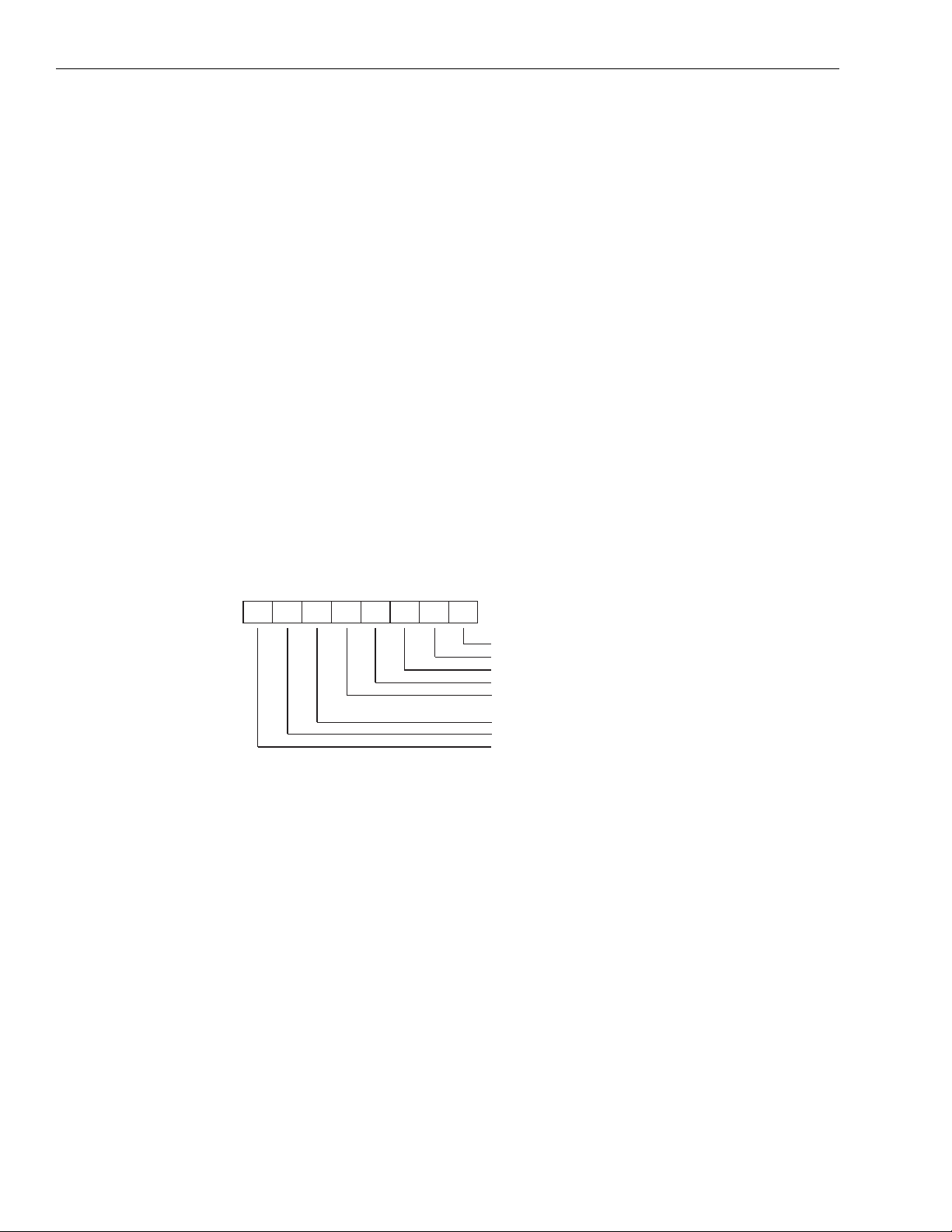
A-16 Driver Routine Descriptions Model 5000 Software Developer’s Guide
Parameters: AxisNum Axis number (0 to 17).
Return Code: State value.
(-1) Invalid axis number.
ReadStatus
Read status register
Declarations: C: short ReadStatus(unsigned short
wAxisNum);
BASIC: DECLARE FUNCTION ReadStatus%(BYVAL
AxisNum%)
Pascal: function ReadStatus(wAxisNum : word) :
word;
Description: This routine reads and returns the contents of the status register according
to the following format:
Figure A-2
Status buffer
Status Port
D6 D2D4 D0D7 D3D5 D1
1: -LIMIT ACTIVE
1: +LIMIT ACTIVE
1: HOME ACTIVE
1: R0 (COUNTER)=0
0: INS SIGNAL=HIGH
1: INS SIGNAL=LOW
1: CONSTANT PULSE RATE
1: DURING PULSE OUTPUT
1: DURING INT SIGNAL ACTIVE
(END OF MOTION)
The bits of the status can be masked out using the following constants or
logical combinations of the following constants:
STS_NLIMIT -Limit input.
STS_PLIMIT +Limit input.
STS_ORIGIN Home input.
STS_ZERO Down counter equals zero.
STS_INPUT General purpose input.
STS_KEEP Output pulses not ramping.
STS_BUSY Operation in progress.
STS_NOT_INT INT not active.
Parameters: AxisNum Axis number (0 to 17).
Return Code: Status word.
(-1) Invalid axis number.

Model 5000 Software Developer’s Guide Driver Routine Descriptions A-17
StartStop
Load start-stop register
Declarations: C: short StartStop(unsigned short
wAxisNum, short sCmd);
BASIC: DECLARE FUNCTION StartStop(BYVAL
AxisNum%, BYVAL Cmd)
Pascal: function StartStop(wAxisNum : word;
sCmd : integer) : integer;
Description: This routine writes the specified value to the start-stop command register.
Depending on the sCmd argument, this routine can start an axis, stop an
axis, or reset an axis interrupt. The format of the command register is as
follows:
Figure A-3
Command buffer
Command Buffer
D6 D2D4 D0D7 D3D5 D1
1: Axis A
Not Used
Command mode selection
D7 D6
00
01
10
11
Command modes are selected from the command buffer.
Command mode
Operating mode
Control mode
Data register
Output pulse mode
Parameters: AxisNum Axis number (0 to 17) or the constant ALL_AXES.
Cmd Start-stop command.
Cmd can be the OR of any of the following:
S_HIGH1 The target pulse rate is set by R2.
S_HIGH2 The target pulse rate is set by R3.
S_RAMPING Ramping is enabled.
S_STOP Pulse output is stopped.
S_START Pulse output is started.
S_INT Interrupt is enabled.
Alternatively, Cmd can be one of the following:
RESET_MOVE (S_STOP)
START1_MOVE (S_START || S_HIGH1 || S_RAMPING)
START2_MOVE (S_START || S_HIGH2 || S_RAMPING)
STOP_MOVE (S_START || S_STOP || S_RAMPING)

A-18 Driver Routine Descriptions Model 5000 Software Developer’s Guide
R
ABORT_MOVE (S_STOP)
START1_MOVE_INT (START1_MOVE || S_INT)
START2_MOVE_INT (START2_MOVE || S_INT)
STOP_MOVE_INT (STOP_MOVE || S_INT)
ABORT_MOVE_INT (ABORT_MOVE || S_INT)
Return Code: (0) No error.
(–1) Invalid axis number.
V elocity1
Load FH1 register
Declarations: C: short Velocity1(unsigned short
wAxisNum, unsigned short wVel);
BASIC: DECLARE FUNCTION Velocity1%(BYVAL
AxisNum%, BYVAL Vel%)
Pascal: function Velocity1(wAxisNum, wVel :
word) : word;
Description: This routine loads the specified slew (high-speed) velocity into register
R2. To convert a v elocity given in pulses per second into register R2 units,
use the following equation:
Slew Velocity()8192()R7()
2
--------------------------------------------------------------------=
where: R7 is the value specified for the Multiplier routine.
f
is the system clock.
clock
The system clock is jumpered to 5 MHz when shipped.
Alternatively, R2 can be thought of as a scaled velocity from 1 to 8191.
The actual velocity in pulses per second is equal to the scaled velocity,
divided by 8192, times the full-scale velocity.
lew Velocity Full Scale Velocity
f
clock
R2
=
----------- -
8192
Parameters: AxisNum Axis number (0 to 17) or the constant ALL_AXES.
Vel Slew velocity in R2 units ranging from 1 to 1FFFh (1 to
8191).
Return Code: (0) No error.
(–1) Invalid axis number or FH1 velocity register value.

Model 5000 Software Developer’s Guide Driver Routine Descriptions A-19
V elocity2
Load FH2 register
Declarations: C: short Velocity2(unsigned short
wAxisNum, unsigned short wVel);
BASIC: DECLARE FUNCTION Velocity2%(BYVAL
AxisNum%, BYVAL Vel%)
Pascal: function Velocity2(wAxisNum, wVel :
word) : word;
Description: This routine loads the specified slew (high-speed) velocity into register
R3. To convert a v elocity giv en in pulses per second into register R3 units,
use the following equation:
Slew Velocity()8192()R7()
3
--------------------------------------------------------------------=
where: R7 is the value specified for the Multiplier routine.
f
is the system clock.
clock
The system clock is jumpered to 5 MHz when shipped.
Alternatively, R3 can be thought of as a scaled velocity from 1 to 8191.
The actual velocity in pulses per second is equal to the scaled velocity,
divided by 8192, times the full-scale velocity.
lew Velocity Full Scale Velocity
f
clock
R3
=
----------- -
8192
WriteReg
Parameters: AxisNum Axis number (0 to 17) or the constant ALL_AXES.
Vel Slew velocity in R3 units ranging from 1 to 1FFFh (1 to
8191).
Return Code: (0) No error.
(–1) Invalid axis number or FH2 velocity register value.
Write register
Declarations: C: short WriteReg(unsigned short wAxisNum
unsigned short wRegister, long lValue);
BASIC: DECLARE FUNCTION WriteReg%(BYVAL
AxisNum%, BYVAL Register%, BYVAL
Value&)
Pascal: function WriteReg(wAxisNum, wRegister :
word; lValue : longint) : integer;
Description: This routine writes the specified value to the specified register.
Parameters: AxisNum Axis number (0 to 17) or the constant ALL_AXES.
Register Register number (0 to 7) corresponding to R0 to R7,
respectively.
Value Value to write.
Return Code: (0) No error.
(–1) Invalid axis number.

B
Profile Utility

B-2 Profile Utility Model 5000 Software Developer’s Guide
If you have installed the 5000 software on your disk, the profile utility program, PRO5000.EXE
is located in the subdirectory in which the software resides.
The Profile program lets you enter physical parameters for a trapezoidal move on any of three
axes. The internal register v alues corresponding to these parameters are calculated and displayed
on the screen. A move can then be triggered either on a single axis, or globally on all the axes
that are enabled. During the move, the number of pulses left to move, the status re gister, and the
state register are displayed for each axis.
This program is useful for optimizing the multiplier n to obtain the greatest velocity resolution
possible. For a complete discussion on optimizing n, see Appendix E of the Model 5000 Technical Reference.
Executing the program
To load the program, type:
pro5000 <base address> <color number>
The program will not load without the necessary arguments. For example, for a 5000 strapped to
a base address of 300h and using color scheme 3, type:
Base address
The base address is the address to which you strapped the 5000 board jumpers — W7, SW1, and
SW2. Appendix C of the Model 5000 Technical Reference contains a map of the entire PC I/O
space. The board is shipped strapped to a base address of 300h.
Color number
A number from 0 to 9 configures the screen colors according to table B-1.
Table B-1
PRO5000 color selections
Note: The first color listed is the foreground, and the second is the background.
pro5000 300 3
Color number Text Highlight Border
0
1
2
3
4
5
6
7
8
9
Yellow/Black
Yellow/Blue
Cyan/Blue
Black/Gray
Blue/Cyan
White/Red
Yellow/Brown
Black/Green
White/Magenta
Gray/Blue
Red/Black
Black/Gray
Black/Gray
White/Black
White/Black
Yellow/Black
Green/Black
Yellow/Black
Yellow/Black
Gray/Black
Brown/Black
Black/Gray
Cyan/Blue
White/Red
Black/Cyan
Lt. Red/Red
Red/Brown
Yellow/Brown
Yellow/Gray
White/Cyan
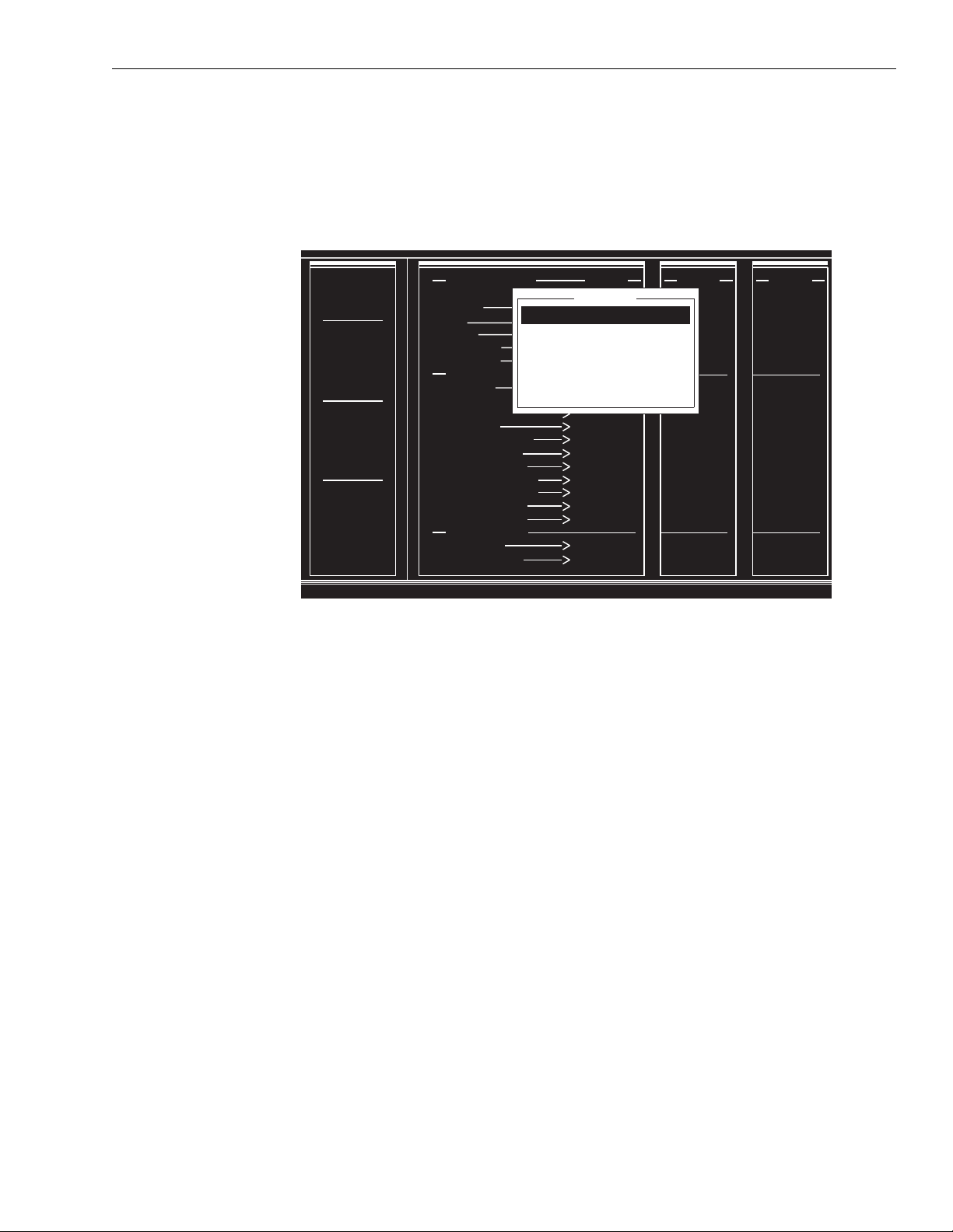
Model 5000 Software Developer’s Guide Profile Utility B-3
Main menu
After pressing any key to continue, the following screen appears:
Figure B-1
Single axis menu screen
CLOCK
SPEED
5 MHz
MOVE
DIRECTION
A UP
B UP
C UP
GLOBAL
CONTROL
A ENABLED
B ENABLED
C ENABLED
RAMPDOWN
INPUTS
A DISABLED
B DISABLED
C DISABLED
,PROFILE ENTRY
Number of Steps
t_total
t_up
t_down
Start Rate
Multiplier
CALCULATED VALUES
Slew Rate
Acceleration
Deceleration
Multiplier
R0 (Pulse Count)
R1 (Low Speed)
R2 (High Speed)
R4 (Acceleration)
R5 (Deceleration)
R6 (Down Point)
R7 (Multiplier)
MOVE MONITORS
Pulses Left
Status / State
Navigating inside the program
To move between choices, press <Up> or <Down>.
Pressing <Enter> is equivalent to pressing <Down>, except pressing <Enter> after the last field
returns the program to the current menu level. Pressing <Ctrl><End> also returns the program to
the current menu level.
AXIS A
10000
MAIN MENU
10
Single Axis Menu
.1
Global Menu
.1
Save File
5
Load File
1.0
Clock: 5 Mhz
Register Display: DEC
1009.581519
Exit Program
10045.94710
10045.94710
1.000576332
10000
5
1009
498
498
51
610
AXIS B
10000
10
.1
.1
5
1.0
1009.581519
10045.94710
10045.94710
1.000576332
10000
5
1009
498
498
51
610
AXIS C
10000
10
.1
.1
5
1.0
1009.581519
10045.94710
10045.94710
1.000576332
10000
5
1009
498
498
51
610
Pressing <Esc> will abort and exit to the previous level menu, restoring all the previous values.
<Delete> and <Backspace> allow you to edit field contents in the usual manner.
Pressing <Insert> toggles the insertion mode. While insertion is active, the cursor appears as a
block.
Monitoring axis configuration
The configuration information window is located on the left-hand side of the screen and displays
clock speed, move direction, global control enables, and rampdown input enables.
Information in this window is defined through menu selections defined in the following
paragraphs.

B-4 Profile Utility Model 5000 Software Developer’s Guide
Single axis menu
To move up or down in the menu, use the <Up> and <Down> arrows. Exit to Main Menu by
pressing <Esc> at any time.
Figure B-2
Active axis: a menu screen
CLOCK
SPEED
5 MHz
MOVE
DIRECTION
A UP
B UP
C UP
GLOBAL
CONTROL
A ENABLED
B ENABLED
C ENABLED
RAMPDOWN
INPUTS
A DISABLED
B DISABLED
C DISABLED
Press Enter to toggle
,PROFILE ENTRY
Number of Steps
t_total
t_up
t_down
Start Rate
Multiplier
CALCULATED VALUES
Slew Rate
Acceleration
Deceleration
Multiplier
R0 (Pulse Count)
R1 (Low Speed)
R2 (High Speed)
R4 (Acceleration)
R5 (Deceleration)
R6 (Down Point)
R7 (Multiplier)
MOVE MONITORS
Pulses Left
Status / State
AXIS A
10000
10
.1
.1
5
1.0
1009.581
10045.94
10045.94
1.000576
10000
1009
5
498
498
51
610
AXIS B
10000
10
MAIN MENU
.1
Active Axis: A
.1
5
Enter parameters
1.0
Execute single axis move
Revise Parameter
1009.581
Move Direction: UP
10045.94
RampDown Inputs: DISABLED
10045.94
Main Menu (Esc)
1.000576
10000
1009
498
498
51
610
5
AXIS C
10000
10
.1
.1
5
1.0
1009.581
10045.94
10045.94
1.000576
10000
5
1009
498
498
51
610
Active Axis
With Active Axis highlighted, make an axis current by pressing <Enter>. Each axis in turn will
advance to the PROFILE ENTRY window where you can set up a profile as discussed below.
The current axis displays in the menu window.
Enter parameters
When highlighted, press <Enter> to enter parameters on the current axis. (The figure above
shows axis A as current.) Each time you enter a value and press <Enter> or press <Enter> to
accept the displayed value, the cursor advances to the next v alue. You can also use the <Up> and
<Down> arrows to selectively enter values. Exit to the Single Axis Menu by pressing <Esc> at
any time, or, after entering the Multiplier value, you will exit to the menu automatically.
Generating a profile
Generating a profile consists of entering a set of typically specified parameters. These parameters calculate the remaining variables and register values necessary to create a move. You can
generate the same profile on all axes, or you can profile all three axes differently and independently. Move status is displayed in the Move Monitor and axis state and configuration are displayed on the left-hand side of the screen.

t_total tupt
slewtdown
++=
Model 5000 Software Developer’s Guide Profile Utility B-5
Setting the parameters
Figure B-3
Trapezoidal parameters
f
Slew Rate
Start Rate
Number of Steps
t_total
Number of Steps
P
UP
T
UP
P
T
SLEW
SLEW
T
TOTAL
P
SD
T
DOWN
This is the total number of pulses during the move.
Number of Steps PupP
++=
slewPsd
This is the total time required for the move.
1
t_up
t_down
Start Rate
Multiplier
At the start of the move, this is the time required to ramp up from the start
velocity (start rate) to the maximum velocity (slew rate). For the 5000,
t_up and t_down can be set independently.
At the end of the move, this is the time required to ramp down from the
maximum velocity to the start velocity.
This is the velocity in pulses per second from which the stepper motor
must start. Stepper motors can not begin a move at zero velocity lik e serv o
motors. The start rate is normally specified on the motor and typically
ranges from 50 to 500 pulses per second.
This is the value of the multiplier constant. The multiplier sets the velocity
resolution of the controller. For a complete discussion on optimizing the
multiplier, see Appendix E.

B-6 Profile Utility Model 5000 Software Developer’s Guide
Calculating the values
Slew Rate
Acceleration
Deceleration
Multiplier
R0 (Pulse Count)
R1 (Low Speed)
R2 (High Speed)
This is the maximum rate in pulses per second during the move. Depending on the acceleration and deceleration, the slew rate may not be attained.
In that case, the velocity cusp will be something less than the slew rate,
and the profile will take on the characteristic of a triangle.
This is the ramp-up acceleration in pulses per second
dependent on ramp-up time or distance and the difference between the
start rate and the slew rate.
This is the ramp-down deceleration in pulses per second
are similar to that of acceleration.
This is the rate multiplier constant. This multiplier is a scaler to maximize
the resolution of the controller registers to the maximum velocity of your
system.
This is the distance value register in units of pulses.
This is the starting velocity value register that sets the v elocity at which the
profile will accelerate to the slew velocity.
This is one of two slew velocity registers (FH1). The second re gister is R3
(FH2). However, PRO5000 uses only R2. Register R3 is designed to
allow you to contour complex profiles by preloading a second or the next
in series of slew velocities for use on the fly.
2
. Acceleration is
2
. Dependencies
R4 (Acceleration)
R5 (Deceleration)
R6 (Down Point)
R7 (Multiplier)
Values that are calculated out of range will generate an error in the CALCULATED VALUES
area, and executing a move is prevented.
This is the acceleration rate register.
This is the deceleration rate register.
This is the rampdown point register. The rampdown point determines
when the profile will begin decelerating to the start velocity.
This is the multiplier register. For a frequency of 5 MHz, a multiplier
value of 610 represents a multiplier of unity.
Execute single axis move
When highlighted, press <Enter> to start a move according to the set parameters on the current
axis. During the move, monitor status and state in the lower region of the PROFILE ENTRY
window.
Pulses Left
Status/State
This is the number of pulses left to move.
This monitors the move status and state in hexadecimal notation.

Model 5000 Software Developer’s Guide Profile Utility B-7
Figure B-4
Status buffer
Status Port
D6 D2D4 D0D7 D3D5 D1
1: -LIMIT ACTIVE
1: +LIMIT ACTIVE
1: HOME ACTIVE
1: R0 (COUNTER)-0
0: INS SIGNAL-HIGH
1: INS SIGNAL-LOW
1: CONSTANT PULSE RATE
1: DURING PULSE OUTPUT
1: DURING INT SIGNAL ACTIVE
(END OF MOTION)
Figure B-5
State buffer
State Buffer
D6 D2D4 D0D7 D3D5 D1
1: R0 (COUNTER)=0
1: DECELERATING
1: SLEW OR CONSTANT PULSE RATE
1: ACCELERATING
NOT USED
Revise parameters
When highlighted, this option allows you to back-calculate the physical parameters from the
register values. Since the physical parameters are calculated in floating point arithmetic and the
register values are calculated in integer arithmetic, the register values represent only an approximation based on the resolution set by the multiplier value.
Each time you press <Enter>, the screen will toggle between entered values and back-calculated
values.
This feature is useful when optimizing n or when analyzing whether a move is possible with the
current set of parameters.
Move direction
When highlighted, this option determines which direction to move. Each time you press
<Enter>, the direction will toggle between UP and DOWN.
RampDown inputs
When highlighted, this option determines whether rampdown inputs are enabled or disabled.
Each time you press <Enter>, the enable will toggle between ENABLED and DISABLED.
When enabled, the rampdown point is determined by external switches mounted on the axis
traverse as well as the value loaded into the rampdown register.
Main menu (esc)
When highlighted, this option returns the program to Main Menu. Alternatively, you can press
<Esc> at any time to return.

B-8 Profile Utility Model 5000 Software Developer’s Guide
Global menu
To move up or down in the menu, use the <Up> and <Down> arrows. Exit to Main Menu by
pressing <Esc> at any time.
Figure B-6
Execute global move menu screen
CLOCK
SPEED
5 MHz
MOVE
DIRECTION
A UP
B UP
C UP
GLOBAL
CONTROL
A ENABLED
B ENABLED
C ENABLED
RAMPDOWN
INPUTS
A DISABLED
B DISABLED
C DISABLED
,PROFILE ENTRY
Number of Steps
t_total
t_up
t_down
Start Rate
Multiplier
CALCULATED VALUES
Slew Rate
Acceleration
Deceleration
Multiplier
R0 (Pulse Count)
R1 (Low Speed)
R2 (High Speed)
R4 (Acceleration)
R5 (Deceleration)
R6 (Down Point)
R7 (Multiplier)
MOVE MONITORS
Pulses Left
Status / State
AXIS A
10000
10
.1
.1
5
1.0
1009.581519
10045.94710
10045.94710
1.000576332
10000
1009
498
498
610
5
51
AXIS B
10000
10
.1
GLOBAL MENU
.1
Execute Global Move
5
1.0
Axis A ENABLED
Axis B ENABLED
1009.581519
Axis C ENABLED
10045.94710
10045.94710
Main Menu (Esc)
1.000576332
10000
5
1009
498
498
51
610
AXIS C
10000
10
.1
.1
5
1.0
1009.581519
10045.94710
10045.94710
1.000576332
10000
5
1009
498
498
51
610
Execute global move
This option allows you to enable any combination of axes A, B, and C, and execute a synchronized move. When highlighted, press <Enter> to start a move.
Axis A (B or C)
When highlighted, this option enables or disables an axis for a global move. Each time you press
<Enter>, the enable will toggle between ENABLED and DISABLED for the respective axis.
Main menu (esc)
When highlighted, this option returns the program to Main Menu. Alternatively, you can press
<Esc> at any time to return.
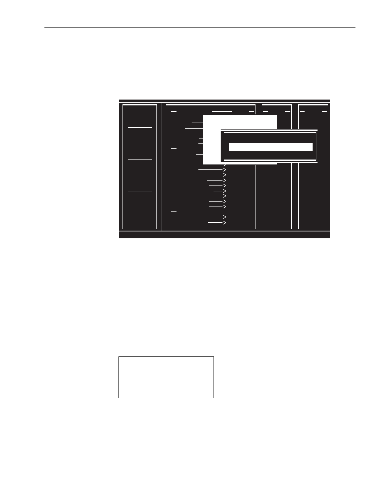
Model 5000 Software Developer’s Guide Profile Utility B-9
Save file/load file
Exit without saving/loading by pressing <Esc> at any time.
Figure B-7
Save file/load file
CLOCK
SPEED
5 MHz
MOVE
DIRECTION
A UP
B UP
C UP
GLOBAL
CONTROL
A ENABLED
B ENABLED
C ENABLED
RAMPDOWN
INPUTS
A DISABLED
B DISABLED
C DISABLED
The Save File option allows you to save parameter settings for later use, and the Load File
option allows you to retrieve parameter settings previously saved.
By default, files are saved or loaded with the extension [.STP], but you can save or load by specifying the entire file name with extension.
,PROFILE ENTRY
Number of Steps
t_total
t_up
t_down
Start Rate
Multiplier
CALCULATED VALUES
Slew Rate
Acceleration
Deceleration
Multiplier
R0 (Pulse Count)
R1 (Low Speed)
R2 (High Speed)
R4 (Acceleration)
R5 (Deceleration)
R6 (Down Point)
R7 (Multiplier)
MOVE MONITORS
Pulses Left
Status / State
AXIS A
10000
MAIN MENU
10
Single Axis Menu
.1
Global Menu
.1
Save File
5
FILE NAME [.STP] :
Load File
1.0
Clock: 5 Mhz
Register Display: DEC
1009.581519
Exit Program
10045.94710
10045.94710
1.000576332
10000
1009
498
498
610
5
51
AXIS B
10000
10
.1
.1
5
1.0
1009.581519
10045.94710
10045.94710
1.000576332
10000
5
1009
498
498
51
610
AXIS C
10000
10
.1
.1
5
1.0
1009.581519
10045.94710
10045.94710
1.000576332
10000
5
1009
498
498
51
610
Clock
When highlighted, this option allows you to select a desired clock frequency. Each time you
press <Enter>, the clock frequency will change according to the following table.
Table B-2
Selecting a clock speed
Frequency (MHz)
0.625
1.25
2.50
5.00*
* Default setting.
Select the base clock rate used by axes A to C.
Note: To obtain the maximum rate of 240,000 pulses per second, use the default clock setting.

B-10 Profile Utility Model 5000 Software Developer’s Guide
Register display
When highlighted, this option allows you to change the displayed values from hexadecimal to
decimal by pressing <Enter>. Each time you press <Enter>, the displayed valued will toggle
between HEX and DEC.
Exit program
When highlighted, press <Enter> to exit to a DOS prompt, or press <Esc> at any time. Exiting
without first saving will cause you to lose all current parameter settings.

C
V isual C++ Demonstration
Program

•
•
C-2 Visual C++ Demonstration Program Model 5000 Software Developer’s Guide
Product overview
This software product is a 16-bit W indo ws program written in Visual C++. It is intended to sho w
Visual C++ programming techniques using the Model 5000 driver functions. See the Model
5000 Visual BASIC Profiler for a more comprehensive demonstration of the Model 5000
capabilities.
System requirements
The system requirements are an IBM-compatible PC with either W indo ws 95 or Windows 3.1, a
mouse, and a properly installed, addressed and jumpered 5000 in the backplane. Please review
the Model 5000 Technical Reference for board installation issues. Minimum host hardware
requirements include two megabytes of RAM and three megabytes of available hard disk space.
Of course, these values are well below the minimum for Windows systems anyway.
Installation
Operation
This program does not require any formal installation. It can be run from either the diskette or
the hard drive. However, we recommend that you install it onto your hard drive simply by copying all files on the diskette onto a discrete hard drive directory. All the files you need to run the
program, including the source, make, library and dynamic linking library (DLL) files are
included on the diskette.
Launch the demo5kcp.exe program in one of the following ways.
From Program Manager in Windows 3.1, double click on the icon or pull down File and
choose Run, then enter demo5kcp.exe in the data field.
From Windows Explorer in Windows 95, double click on the icon or click on Start, choose
Run and enter demo5kcp.exe in the data field.
Once you 1aunch the program, the main user window shown in Figure C-1 will appear.

Model 5000 Software Developer’s Guide Visual C++ Demonstration Program C-3
Figure C-1
5000 C++ demonstration program main user window
The demo will default at values that will run most stepper motors. There may be some aspects of
your system that could complicate operation. The following can help you with many common
configuration problems.
NOTE
The demo is set to use conservative values that will run most stepper motors. To change a register value, highlight its data field and enter the desired value in place of the previous value. Then
either click in another data field or the Start command and the value will be accepted. Pressing
Stop will abruptly halt the move.
Program architecture
The intent of this program is to show the use of the 5000 driver functions and to keep the code
simple. Thus, many desirable features were left out for simplicity sake. The result is a barebones demo. For a more complete demo, please see the 5000 Visual BASIC Profiler.
The board and program are set up for operation at address 300h which is available on most PC configurations. If another board occupies that address space in
your backplane and you don't want to change its address, you will need to alter
both the board's hardware and software. Please see Model 5000 Technical Reference for instructions on how to change the address jumpers (SW1 and SW2). To
change the board address for the program, you will need to go into the
BOARD_ADDRESS macro (in the source code) and set the address to a value
that does not conflict with any other board in your backplane and agrees with
your jumper settings. Then rebuild the project under your Visual C++ development environment.
For simplicity sake, the source file is partitioned into two sections, Section1 and Section2.
Section1 derives the application and window classes. To simplify matters, it will not be discussed. Section2 delineates the classes containing the driver functions and will be discussed in
detail below.

C-4 Visual C++ Demonstration Program Model 5000 Software Developer’s Guide
Class Stepper1 is the base class for the 5000 board application object. (See Source code below.)
The only operative function is the constructor. Other data and function members may be added
as desired.
In the Stepper1 class constructor, functions InitSw and InitBoard are called upon program
startup. These functions can only be called once per program instance so the constructors are the
logical place to put them. Functions InitSw, InitBoard and other 5000 routines do return values.
Although the return values are not used in this example for simplicity, we recommend that you
use them in your application in order to ensure that the functions complete successfully.
In the PushedStart function, driver routines that load the registers are called. Though the
sequence in which the functions are called is typical, it is not critical, provided that StartStop is
the last function called. Note that the Distance and PointDown functions pass [LONG] values.
The PushedStop calls the StartStop function while in the stop mode. Additionally, in the timer
function, the pulse count is sampled every 10 ms.
// Section 2
//- A base class for the 5000
class Stepper1
{
public:
Stepper1(); //-The constructor
};
//- An instance of the Stepper class.
Stepper1 Stepper1Inst;
{
(void) InitSw(); //-These functions are called (void)
InitBoard(BOARD_ADDRESS); //-upon startup
}
void UserWindow: :PushedStop()
{
(void) StartStop (AXIS, S_STOP); //-Stop the move
}
void UserWindow: :PushedStart()
{
char temp [30];
char *stop;
//- Get data from edit boxes
GetDlgItemText(hR0, temp, 30); //- Note conversion
_Pulses = strtol(temp, &stop, 10); //- from text to long
StartVel = GetDlgItemInt(hR1);
Vel1 = GetDlgItemInt (hR2);
Accel = GetDlgItemInt(hR3);
Decel = GetDlgItemInt(hR4);
GetDlgItemText(hR5, temp, 30); //-Note conversion Dp =
strol(temp, &stop, 10); //-from text to long
Multi = GetDlgItemInt(hR6);
//-Load registers
(void) Distance(AXIS, Pulses);

Model 5000 Software Developer’s Guide Visual C++ Demonstration Program C-5
(void) Multiplier(AXIS, Mult);
(void) LowVelocity (AXIS, StartVel);
(void) Velocity1 (AXIS, vel1);
(void) Acceleration(AXIS, Accel);
(void) Deceleration (AXIS, Decel);
(void) DownPoint (AXIS, Dp);
(void) ModeSelect(AXIS, POSMODE_DOWN);
(void) StartStop (AXIS, RESET_MOVE);
(void) StartStop(AXIS, START1_MOVE); //- Start the move
}
//- The timer function
void UserWindow::OnTimer(UNIT id)
{
for(i=0; i<100; i++) s[i] = '\0'; //-Initialize the array
ostream ostr(s, 100); //-Instantentuate ostr
ostr << PulseLeft (AXIS) ; //-Redirect pulses out to ostr
SetDlgItemText(hPulses, s); //-Display the pulses
}

D
V isual BASIC
Demonstration Program

D-2 Visual BASIC Demonstration Program Model 5000 Software Developer’s Guide
User's guide
Product overview
The 5000 Visual BASIC Profiler Utility demonstrates Model 5000's capabilities. The program
was developed in Visual BASIC for l6-bit and compatible Windows environments. It runs on a
IBM compatible PC equipped with W indows 3.1 or W indo ws 95 with a Model 5000 stepper card
in the backplane. The program enables users to enter values into a plethora of data fields in a
convenient graphical user interface (GUI).
Installation
Installation is fairly simple. We assume that you have a properly installed, configured and jumpered 5000 board in your backplane. If you have any doubts about this, please re vie w the Model
5000 Technical Reference for all hardware installation issues. To install the software, follow the
common procedure of inserting the disk1 setup diskette into your 3
setup.exe. How you do this will depend on whether you work in the Windows 3.1 or Windows
95 environments.
1
/
" floppy drive and running
2
Windows 3.1
In the Program Manager, pull down the File menu and select Run. You will get a dialogue box
with one data field. Type a:\setup, or b:\setup and press <enter> or click OK. Windows 3.1 will
run the installation procedure. Follow the steps as prompted by this procedure.
Windows 95
Click on the Start button at the lower left-hand part of your screen. Click on Run. Choose
Browse and select Drive A: (or B: where appropriate). Click OK or press <enter> and Windows
will run the installation procedure. Follow the steps as prompted by this procedure.

Model 5000 Software Developer’s Guide Visual BASIC Demonstration Program D-3
Operation
Double click the Prof1 icon. The main user window shown in Figure D-1 will appear.
Figure D-1
5000 Profiler main user window
See Table D-2.
See Table D-1. See Table D-3.

D-4 Visual BASIC Demonstration Program Model 5000 Software Developer’s Guide
On program startup, the demo displays conservative default values that will run almost any stepper motor. The default number of axes is 1. If you have a board with two or three axes, click on
the number of axes and change to two or three. To start motion, click START1, START2,
START3, or START ALL. The pulses left will be shown on the bottom right of the user window.
NOTE
The demo user window is comprised of two sections. On the left side of the window, registers
R0 through R7 are displayed. The user can change the register values by clicking on the desired
value. The register limits are displayed on the bottom left of the window in fields LOW and
HIGH. It is the user's responsibility to enter values that will produce the desired motion. It is
possible to choose values that will not produce motion.
On the right side of the screen, physical parameters may be entered, the limits are displayed on
the right side of the screen in the LOW and HIGH data fields. As with the registers, it is possible
to choose physical values that will not produce motion. Descriptions of the physical data fields
in the main user window follow.
The user window contains data fields, command buttons and menu items. Most of the window's
items consist of input or display fields. There are nine command buttons and two menu items.
The following is a description of the user window items.
If you choose a number of axes that is greater than your board allows, you will
get an overflow error when you try to start the unsupported axis.
Table D-1
Physical data fields
Data field Description
R0
R1
R2
R3
R4
R5
R6
R7
This input/display field contains distance information.
The value is in pulses.
This input/display field contains a register value that sets the start value.
This is the input/display field that contains a register value that sets the final
velocity .
This display field shows the register value and sets the second final v elocity.
In this version, R3 is set to R2’s value as only one final velocity is
supported.
This input/display field contains a register value that sets the acceleration
rate.
This input/display field contains a register value that sets the deceleration
rate.
This input/display field sets the start of the ramp-down point.
This input/display field sets the multiplier register.

Model 5000 Software Developer’s Guide Visual BASIC Demonstration Program D-5
Table D-2
Velocity data fields
Data field Description
LOW and High
Start V elocity
V elocity1
V elocity2
Table D-3
Accel and decel data fields
Data field Description
VALUE
LOW and HIGH
Accel Rate
Accel Time
Decel Rate
Decel Time
This input/display field shows the maximum and minimum start velocities
based on register R1 limits.
This input/display field sets the start velocity. The value displayed is in
pulses per second.
This input/display field sets the final velocity of the motor.
This input/display field shows the final velocity of the motor . In this v ersion,
Velocity2 is always set to Velocity1.
Actual user inputted value.
These fields show the upper and lower limits for each parameter.
This input/display field sets the acceleration rate of the motor.
This display field shows the acceleration time of the motor.
This input/display field sets the deceleration rate of the motor.
This display field shows the deceleration time of the motor.
Menu items
Table D-4
Miscellaneous data fields
Data field Description
LOW and HIGH
Low
High
Axis
Board Frequency
Extra Pulses at
End
Pulses Left
In addition to the various input and display fields shown in Figure D-1, there are two menu items
from which to select at the top of the window. They are described below.
File
Options
These display fields show the acceleration and deceleration time low and
high limits.
This display field shows the minimum value of the register field selected for
input.
This display field shows the maximum value of the register field selected for
input.
This display field shows the current active axis.
This display field shows the board frequency selected.
This display field shows the extra pulses at the end of a move.
This display field shows the pulses left during a move.
Pull this menu down to exit.
Pull this menu down to change the active axis and to change the board frequency used in calculations.

D-6 Visual BASIC Demonstration Program Model 5000 Software Developer’s Guide
Developer's guide
This section describes the development process for this product. Since none of the source code is
available, this section is for your information only.
Program architecture
The 5000 Profiler Utility is event-driven from either user input or hardware response. The flow
diagram in Figure D-2 shows how the central e vent is an input or command from the user. Figure
D-3 shows the text-box value assignments.
Figure D-2
Flow diagram for 5000 Visual BASIC Profiler

Model 5000 Software Developer’s Guide Visual BASIC Demonstration Program D-7
Figure D-3
Text box value assignments for 5000 Profiler main user window
Program organization
The program consists of five code modules and four main form modules. For those unfamiliar
with Visual BASIC, code modules are the guts of the program. They instruct the computer and
board to perform various functions. Form modules enable users to talk to the code modules in a
user-friendly way. They ensure that telling the program to execute certain functions is merely a
matter of clicking on command buttons and entering data in fields.
Form module descriptions
PROFSK.FRM is the program's main form module. It contains the three general objects and 72
procedure objects described below. The other three form modules — ADDR.FRM,
AXISFR.FRM, and FREQ.FRM — are also described.

D-8 Visual BASIC Demonstration Program Model 5000 Software Developer’s Guide
Table D-5
Code module descriptions
Library Module type Action
5000H.BAS
DECLARE.BAS
STARTUP.BAS
INIT.BAS
CALCDATA.BAS
GENERAL OBJECT,
DECLARATION
GENERAL OBJECT,
DECLARATION
GENERAL OBJECT,
MAIN PROCEDURE
GENERAL OBJECT,
DECLARATION
GENERAL OBJECT,
CALCULATE DATA
PROCEDURE
This code module contains 5000 board register
constants, DLL function declarations, and all
DLL prototypes.
This code module contains program constants,
user defined types, array variables, and flag
variable definitions.
This code module is called on program startup,
it calls the INIT subroutine to initialize the
array.
This code module initializes the array.
This code module performs necessary
calculations as a result of user input. It is called
by the CALC form object (see form module
descriptions).
Table D-6
Form module descriptions
Module Object Description
PROFSK.FRM
ADDR.FRM
AXISFR.FRM
FREQ.FRM
Declarations
CalculateData
TextClear
Calc
StartCmd
StopCmd
TextXVal
LabelX
MenuX
GENERAL OBJECT: This procedure declares Window API
functions for use in the program.
GENERAL OBJECT: This procedure calculates resultant
values from a data field input change. It also displays
calculated data.
GENERAL OBJECT: This procedure clears data fields prior
to new data being displayed.
FORM OBJECT: This procedure evaluates which
calculations need to be performed according to the priority of
active input flags.
FORM OBJECT: This procedure calls the 5000 board
functions and starts motion.
FORM OBJECT: This procedure calls the 5000 board
function and stops motion.
FORM OBJECTS: These procedures display input and output
data on the user window data fields (X is a variable). There
are three main procedure types users can follow in these
fields. First, KeyPress procedures assign the text box v alues to
its corresponding variable upon an <enter> keystroke.
Second, MouseDown clears the text box. Third, LostFocus
assigns the text box value to the variable in the event that the
user does not press <enter> after selecting a text box.
FORM OBJECTS: These procedures only display labels on
the user window.
FORM OBJECTS: These procedures display the menu items
on the user window.
This form module contains address selection command
buttons which select the desired frequency.
This form module contains axis selection command buttons
which select the active axis.
This form module contains frequency selection command
buttons which select the desired frequency.

Index
A
Acceleration A-3
Acceleration/deceleration units 3-3
Axis command routines 5-2
Axis data reporting routines 5-3
B
Base address B-2
Borland or Turbo C/C++ 1-3
Borland Turbo Pascal 1-4
C
Clock B-9
Clockoff A-4
Color number B-2
Compiling and linking 1-2
D
Deceleration A-5
Developer’s guide D-6
Disable input interrupt A-9
Disable IRQ lines A-6
Disable motor output A-4
DisableIRQ A-6
Distance A-6
Distance units 3-3
DownPoint A-7
Driver routine descriptions A-1
E
Enable input interrupt A-10
Enable IRQ line A-7
EnableIRQ A-7
Enabling interrupts 4-2
Example programs 2-1
Executing the program B-2
Exit program B-10
G
General notes on using interrupts 4-3
Global menu B-8
H
Homing 2-6
I
InitBoard A-8
Initialize board A-8
Initialize software A-9
Initialization and hardware control routines 5-2
InitSw A-9
InputAlertOff A-9
InputAlertOn A-10
Install interrupt hooks A-10
Installation C-2, D-2
Installing the 5000 software 1-2
Interrupt handling 4-1
InterruptHooks A-10
Interrupts in BASIC 4-2
Interrupts in C or Pascal 4-2
Introduction 2-2, 4-2, 5-2
IOControl A-11
ISBusy A-11
i-1

L
Load acceleration register A-3
Load deceleration register A-5
Load distance register A-6
Load downpoint register A-7
Load FH1 register A-18
Load FH2 register A-19
Load mode select register A-12
Load multiplier register A-13
Load start-stop register A-17
Load start velocity register A-12
LowVelocity A-12
M
Main menu B-3
Menu items D-5
Microsoft C or Microsoft QuickC 1-2
Microsoft QuickBASIC 1-3
ModeSelect A-12
Monitoring axis configuration B-3
Move parameters 3-1
Move program in BASIC 2-3
Move program in C 2-2
Move program in Pascal 2-4
Multiplier A-13
R
Ranges 3-2
Read busy bit A-11
Read state buffer A-15
Read status register A-16
Reading position 2-8
ReadState A-15
ReadStatus A-16
Register display B-10
Return distance left A-15
Routine summary 5-1
S
Save file/load file B-9
Set GP output HIGH A-14
Set GP output LOW A-14
Single axis menu B-4
StartStop A-17
System requirements C-2
T
Trapezoidal point-to-point move 2-2
U
N
Navigating inside the program B-3
Notational conventions A-3
O
Operation C-2, D-3
OutputHigh A-14
OutputLow A-14
P
Product overview C-2, D-2
Profile utility B-1
Program architecture C-3, D-6
Program organization D-7
Programming fundamentals 1-4
Programming overview 1-1
PulsesLeft A-15
User’s guide D-2
V
Velocity mode 2-5
Velocity units 3-2
Velocity1 A-18
Velocity2 A-19
Visual BASIC demonstration program D-1
Visual C++ demonstration program C-1
W
Write I/O control register A-11
Write register A-19
WriteReg A-19
i-2

Keithley Instruments, Inc.
28775 Aurora Road
Cleveland, Ohio 44139
Printed in the U.S.A.
 Loading...