

Page 1

M1700
Series of Digital I/O To Computer Interfaces
User Guide
A GREATER MEASURE OF CONFIDENCE
Page 2

WARRANTY
Hardware
Keithley Instruments, Inc. warrants that, for a period of one (1) year from the date of shipment (3 years for Models 2000, 2001, 2002, 2010 and 2700), the
Keithley Hardware product will be free from defects in materials or workmanship. This warranty will be honored provided the defect has not been caused
by use of the Keithley Hardware not in accordance with the instructions for the product. This warranty shall be null and void upon: (1) any modification of
Keithley Hardware that is made by other than Keithley and not approved in writing by Keithley or (2) operation of the Keithley Hardware outside of the
environmental specifications therefore.
Upon receiving notification of a defect in the Keithley Hardware during the warranty period, Keithley will, at its option, either repair or replace such Keithley Hardware. During the first ninety days of the warranty period, Keithley will, at its option, supply the necessary on site labor to return the product to the condition prior to
the notification of a defect. Failure to notify Keithley of a defect during the warranty shall relieve Keithley of its obligations and liabilities under this warranty.
Other Hardware
The portion of the product that is not manufactured by Keithley (Other Hardware) shall not be covered by this warranty, and Keithley shall have no duty of
obligation to enforce any manufacturers' warranties on behalf of the customer. On those other manufacturers’ products that Keithley purchases for resale,
Keithley shall have no duty of obligation to enforce any manufacturers’ warranties on behalf of the customer.
Software
Keithley warrants that for a period of one (1) year from date of shipment, the Keithley produced portion of the software or firmware (Keithley Software) will
conform in all material respects with the published specifications provided such Keithley Software is used on the product for which it is intended and otherwise in accordance with the instructions therefore. Keithley does not warrant that operation of the Keithley Software will be uninterrupted or error-free and/
or that the Keithley Software will be adequate for the customer's intended application and/or use. This warranty shall be null and void upon any modification
of the Keithley Software that is made by other than Keithley and not approved in writing by Keithley.
If Keithley receives notification of a Keithley Software nonconformity that is covered by this warranty during the warranty period, Keithley will review the
conditions described in such notice. Such notice must state the published specification(s) to which the Keithley Software fails to conform and the manner
in which the Keithley Software fails to conform to such published specification(s) with sufficient specificity to permit Keithley to correct such nonconformity. If Keithley determines that the Keithley Software does not conform with the published specifications, Keithley will, at its option, provide either the
programming services necessary to correct such nonconformity or develop a program change to bypass such nonconformity in the Keithley Software.
Failure to notify Keithley of a nonconformity during the warranty shall relieve Keithley of its obligations and liabilities under this warranty.
Other Software
OEM software that is not produced by Keithley (Other Software) shall not be covered by this warranty, and Keithley shall have no duty or obligation to
enforce any OEM's warranties on behalf of the customer.
Other Items
Keithley warrants the following items for 90 days from the date of shipment: probes, cables, rechargeable batteries, diskettes, and documentation.
Items not Covered under Warranty
This warranty does not apply to fuses, non-rechargeable batteries, damage from battery leakage, or problems arising from normal wear or failure to follow
instructions.
Limitation of Warranty
This warranty does not apply to defects resulting from product modification made by Purchaser without Keithley's express written consent, or by misuse
of any product or part.
Disclaimer of Warranties
EXCEPT FOR THE EXPRESS WARRANTIES ABOVE KEITHLEY DISCLAIMS ALL OTHER WARRANTIES, EXPRESS OR IMPLIED, INCLUDING WITHOUT LIMITATION, ALL IMPLIED WARRANTIES OF MERCHANTABILITY AND FITNESS FOR A PARTICULAR PURPOSE. KEITHLEY DISCLAIMS ALL WARRANTIES WITH RESPECT TO THE OTHER HARDWARE AND OTHER SOFTWARE.
Limitation of Liability
KEITHLEY INSTRUMENTS SHALL IN NO EVENT, REGARDLESS OF CAUSE, ASSUME RESPONSIBILITY FOR OR BE LIABLE FOR: (1)
ECONOMICAL, INCIDENTAL, CONSEQUENTIAL, INDIRECT, SPECIAL, PUNITIVE OR EXEMPLARY DAMAGES, WHETHER CLAIMED
UNDER CONTRACT, TORT OR ANY OTHER LEGAL THEORY, (2) LOSS OF OR DAMAGE TO THE CUSTOMER'S DATA OR PROGRAMMING, OR (3) PENALTIES OR PENALTY CLAUSES OF ANY DESCRIPTION OR INDEMNIFICATION OF THE CUSTOMER OR OTHERS FOR
COSTS, DAMAGES, OR EXPENSES RELATED TO THE GOODS OR SERVICES PROVIDED UNDER THIS WARRANTY.
Keithley Instruments, Inc. 28775 Aurora Road • Cleveland, Ohio 44139 • 440-248-0400 • Fax: 440-248-6168
1-888-KEITHLEY (534-8453) • www.keithley.com
Sales Offices:BELGIUM: Bergensesteenweg 709 • B-1600 Sint-Pieters-Leeuw • 02-363 00 40 • Fax: 02/363 00 64
CHINA: Yuan Chen Xin Building, Room 705 • 12 Yumin Road, Dewai, Madian • Beijing 100029 • 8610-6202-2886 • Fax: 8610-6202-2892
FINLAND: Tietäjäntie 2 • 02130 Espoo • Phone: 09-54 75 08 10 • Fax: 09-25 10 51 00
FRANCE: 3, allée des Garays • 91127 Palaiseau Cédex • 01-64 53 20 20 • Fax: 01-60 11 77 26
GERMANY: Landsberger Strasse 65 • 82110 Germering • 089/84 93 07-40 • Fax: 089/84 93 07-34
GREAT BRITAIN: Unit 2 Commerce Park, Brunel Road • Theale • Berkshire RG7 4AB • 0118 929 7500 • Fax: 0118 929 7519
INDIA: Flat 2B, Willocrissa • 14, Rest House Crescent • Bangalore 560 001 • 91-80-509-1320/21 • Fax: 91-80-509-1322
ITALY: Viale San Gimignano, 38 • 20146 Milano • 02-48 39 16 01 • Fax: 02-48 30 22 74
JAPAN: New Pier Takeshiba North Tower 13F • 11-1, Kaigan 1-chome • Minato-ku, Tokyo 105-0022 • 81-3-5733-7555 • Fax: 81-3-5733-7556
KOREA: 2FL., URI Building • 2-14 Yangjae-Dong • Seocho-Gu, Seoul 137-888 • 82-2-574-7778 • Fax: 82-2-574-7838
NETHERLANDS: Postbus 559 • 4200 AN Gorinchem • 0183-635333 • Fax: 0183-630821
SWEDEN: c/o Regus Business Centre • Frosundaviks Allé 15, 4tr • 169 70 Solna • 08-509 04 679 • Fax: 08-655 26 10
SWITZERLAND: Kriesbachstrasse 4 • 8600 Dübendorf • 01-821 94 44 • Fax: 01-820 30 81
TAIWAN: 1FL., 85 Po Ai Street • Hsinchu, Taiwan, R.O.C. • 886-3-572-9077• Fax: 886-3-572-9031
4/02
Page 3

User Guide
for
the
M
1700
Digital
Series
I/O
To
Computer Interfaces
R
vision
Copyright Keithley MetraByte
Pan
A
Number:
-
June
Of
1991
24403
Corp.
1991
Page 4

All
products manufactured
materials
the
warranty
This
original
period
warranty
and
worksmanship for
purchaser.
will,
does not apply
by
Any product
at
the
option
Warranty Information
Keithley MetraByte
a
period
of
that
is
of
Keithlq
to
products
damaged
are
one
year
found
to
MetraByte,
warranted
horn
be
by
improper
Warning
the
date
defective
be
repaired
against
of
delivery to
within
or
use.
defective
the
replaced.
gdthlep
use
of
level
of
Information
reliable.
for
of
or otherwise under
However,
the
use
third
parties that may result
Note:
MetraByte"
Basic"
Is
MetraEyte
this
product.
rcliabiiity
furnished
of
such information nor
is
a
a
trademark
p8sumes
This
suitabIe
by
the
KeiMey
any
patent
trademark of
of
Dartrnouth
no
liability
product
for
is
not designed with components
use
in
life
Disclaimer
Keithley MetraByte
MetraByte
from
rights
Keithley
Corporation assumes
for
any
its
use.
of
Keithley
MehaByte Corporation.
College.
for
support
is
believed
damages
consequent
or
critical
to
be
accurate
no
infringements of patents
No
license
is
granted
MetraByte
Corporation.
to
the
of
applications.
and
responsibility
or
other
by
implication
a
rights
IBMQ
is
a
registered
PC.
XT,
AT,
PS/2,
tional Business Machines
Microsoft@
Turbo
is
t3
is
a
bademark
and
a
registered trademark
registered trademark of Borland
oflnternational Business Machines Corporation.
Micro
Channel Architecture@
Corporation.
of
-
are trademarks
Microsoft Corporation.
International
iv
-
of
Intema-
Page 5

New Contact Information
Keithley Instruments, Inc.
28775 Aurora Road
Cleveland, OH 44139
Technical Support: 1-888-KEITHLEY
Monday – Friday 8:00 a.m. to 5:00 p.m (EST)
Fax: (440) 248-6168
Visit our website at http://www.keithley.com
Page 6

Safety Precautions
The following safety precautions should be observed before using
this product and any associated instrumentation. Although some instruments and accessories would normally be used with non-hazardous voltages, there are situations where hazardous conditions
may be present.
This product is intended for use by qualified personnel who recognize shock hazards and are familiar with the safety precautions required to avoid possible injury. Read and follow all installation,
operation, and maintenance information carefully before using the
product. Refer to the manual for complete product specifications.
If the product is used in a manner not specified, the protection provided by the product may be impaired.
The types of product users are:
Responsible body is the individual or group responsible for the use
and maintenance of equipment, for ensuring that the equipment is
operated within its specifications and operating limits, and for ensuring that operators are adequately trained.
Operators use the product for its intended function. They must be
trained in electrical safety procedures and proper use of the instrument. They must be protected from electric shock and contact with
hazardous live circuits.
Maintenance personnel perform routine procedures on the product
to keep it operating properly, for example, setting the line voltage
or replacing consumable materials. Maintenance procedures are described in the manual. The procedures explicitly state if the operator
may perform them. Otherwise, they should be performed only by
service personnel.
Service personnel are trained to work on live circuits, and perform
safe installations and repairs of products. Only properly trained service personnel may perform installation and service procedures.
Keithley products are designed for use with electrical signals that
are rated Installation Category I and Installation Category II, as described in the International Electrotechnical Commission (IEC)
Standard IEC 60664. Most measurement, control, and data I/O signals are Installation Category I and must not be directly connected
to mains voltage or to voltage sources with high transient over-voltages. Installation Category II connections require protection for
high transient over-voltages often associated with local AC mains
connections. Assume all measurement, control, and data I/O connections are for connection to Category I sources unless otherwise
marked or described in the Manual.
Exercise extreme caution when a shock hazard is present. Lethal
voltage may be present on cable connector jacks or test fixtures. The
American National Standards Institute (ANSI) states that a shock
hazard exists when voltage levels greater than 30V RMS, 42.4V
peak, or 60VDC are present. A good safety practice is to expect
that hazardous voltage is present in any unknown circuit before
measuring.
Operators of this product must be protected from electric shock at
all times. The responsible body must ensure that operators are prevented access and/or insulated from every connection point. In
some cases, connections must be exposed to potential human contact. Product operators in these circumstances must be trained to
protect themselves from the risk of electric shock. If the circuit is
capable of operating at or above 1000 volts, no conductive part of
the circuit may be exposed.
Do not connect switching cards directly to unlimited power circuits.
They are intended to be used with impedance limited sources.
NEVER connect switching cards directly to AC mains. When connecting sources to switching cards, install protective devices to limit fault current and voltage to the card.
Before operating an instrument, make sure the line cord is connected to a properly grounded power receptacle. Inspect the connecting
cables, test leads, and jumpers for possible wear, cracks, or breaks
before each use.
When installing equipment where access to the main power cord is
restricted, such as rack mounting, a separate main input power disconnect device must be provided, in close proximity to the equipment and within easy reach of the operator.
For maximum safety, do not touch the product, test cables, or any
other instruments while power is applied to the circuit under test.
ALWAYS remove power from the entire test system and discharge
any capacitors before: connecting or disconnecting cables or jumpers, installing or removing switching cards, or making internal
changes, such as installing or removing jumpers.
Do not touch any object that could provide a current path to the common side of the circuit under test or power line (earth) ground. Always
make measurements with dry hands while standing on a dry, insulated
surface capable of withstanding the voltage being measured.
The instrument and accessories must be used in accordance with its
specifications and operating instructions or the safety of the equipment may be impaired.
Do not exceed the maximum signal levels of the instruments and accessories, as defined in the specifications and operating information, and as shown on the instrument or test fixture panels, or
switching card.
When fuses are used in a product, replace with same type and rating
for continued protection against fire hazard.
Chassis connections must only be used as shield connections for
measuring circuits, NOT as safety earth ground connections.
If you are using a test fixture, keep the lid closed while power is applied to the device under test. Safe operation requires the use of a
lid interlock.
5/02
Page 7

If or is present, connect it to safety earth ground using the
wire recommended in the user documentation.
!
The symbol on an instrument indicates that the user should refer to the operating instructions located in the manual.
The symbol on an instrument shows that it can source or measure 1000 volts or more, including the combined effect of normal
and common mode voltages. Use standard safety precautions to
avoid personal contact with these voltages.
The WARNING heading in a manual explains dangers that might
result in personal injury or death. Always read the associated information very carefully before performing the indicated procedure.
The CAUTION heading in a manual explains hazards that could
damage the instrument. Such damage may invalidate the warranty.
Instrumentation and accessories shall not be connected to humans.
Before performing any maintenance, disconnect the line cord and
all test cables.
To maintain protection from electric shock and fire, replacement
components in mains circuits, including the power transformer, test
leads, and input jacks, must be purchased from Keithley Instruments. Standard fuses, with applicable national safety approvals,
may be used if the rating and type are the same. Other components
that are not safety related may be purchased from other suppliers as
long as they are equivalent to the original component. (Note that selected parts should be purchased only through Keithley Instruments
to maintain accuracy and functionality of the product.) If you are
unsure about the applicability of a replacement component, call a
Keithley Instruments office for information.
To clean an instrument, use a damp cloth or mild, water based
cleaner. Clean the exterior of the instrument only. Do not apply
cleaner directly to the instrument or allow liquids to enter or spill
on the instrument. Products that consist of a circuit board with no
case or chassis (e.g., data acquisition board for installation into a
computer) should never require cleaning if handled according to instructions. If the board becomes contaminated and operation is affected, the board should be returned to the factory for proper
cleaning/servicing.
Page 8

Contents
CHAPTER
CHAPTER
CHAPTER
1
:
INTRODUCTION
Getting Started
Defautl Mode
RS-232
RS-485
SIOOO
2:
FUNCTIONAL DESCRIPTION
3:
COMMUNICATIONS
Introduction
RS-232C
RS-485
&
Quick Hook-up to a
Software
Single Module Connection
Multi-pany Connection
Software Considerations
Changing Baud Rate
Using A Daisy Chain With A Dumb Terminal
.........................................
RS-485
Communications Delay
.....................................
......................................
RS-485
Quick Hook-Up
.....................................
.......................................
........................................
Multidrop System
1-1
1.1
...........................
RS-232
port
......................
.............................
...............................
..............................
................................
...................
..............................
...............................
1.2
. 1-3
1.4
3.1
3.2
3.2
3.2
3.3
3.4
3.4
3-4
3.5
3.6
CHAPTER
4:
1700
COMMAND SET
Command Structure
Data Structure
Bit
Addresses
Logic Convention
Write Protection
Miscellaneous Protocol
Response Structure
Long Form Responses
Checksum
Command Checksum
Response Checksums
Checksum Calculation
1700
ACKnowledge (ACK)
Assign Input Bit (AIB)
Assign
Assign Output Bit (AOB)
Assign Output Position (AOP)
Assign Input/Output
Clear
Clear Position (CP)
Set Bit (SB)
Set Position
Clear Events
Continuous Input Address (CIA)
Continuous Mode-Change (CMC)
Continuous Mode Disable
........................................
Command
Input
Bit
(CB)
..................................
......................................
......................................
....................................
.....................................
Notes
.............................
...................................
.................................
..................................
.................................
.................................
Set
..................................
................................
................................
Position (AIP)
.............................
..............................
...........................
(AIO)
.............................
....................................
.................................
.....................................
(SP)
..................................
(CE)
..................................
.........................
........................
(CMD)
........................
4.1
4.1
4.2
4.2
4.2
4.3
4.3
4.3
4.4
4.4
4.4
4-4
4.6
4.6
4.7
4.7
4.7
4.7
4.8
4.8
4.8
4.8
4.8
4.9
4-10
4-10
4-10
-v-
Page 9

Contents
Continuous Mode-Input (CMI)
Continuous Mode-Timer (CMT)
Digital Input
Digital Output
Events Read & Clear (EC)
Identification (ID)
Initial Value
Read Assignment (RA)
Read Assignment Bit (RAB)
Read Assignment Position (RAP)
Read Bit
Read Position (RP)
Read Continuous Mode
Read Continuous Timer (RCT)
Read Input Address (RIA)
Read Data (RD)
Read Identification
Read Initial Value (RIV)
Read Input Sit
Read Input Position (RIP)
Read Setup
Remote Reset
Read Watchdog Timer
Setup Command
Watchdog Timer
Write Enabte
Error Messages
Address Error
Badchecksum.,
Command
Output
Parity Error
Syntax Error
Value Error
Write Protected
(DI)
.................................
(DO)
................................
.................................
(IV)
.................................
..............................
(RB)
...................................
................................
(RCM)
.................................
(RID)
.............................
.............................
(RIB)
...............................
(RSU)
Error
Error
....................................
....................................
................................
(RR)
...............................
(RWT)
(SU)
..............................
(wr)
..............................
(WE)
................................
...................................
...................................
................................
.................................
...................................
...................................
..................................
..........................
.........................
............................
...........................
........................
.........................
.........................
............................
............................
..........................
4-10
4-10
4-11
4-11
4-11
4-12
4-12
4-12
4-13
4-13
4-13
4-13
4-13
4-14
4-14
4-14
4-15
4-15
4-15
4-15
4-16
4-16
4-16
4-17
4-17
4-18
4-18
4-18
4-18
4-19
4-19
4-19
4-19
4-19
4-19
CHAPTER
5:
SETUP INFORMATION
Command Syntax
B~el
Byle2
Bytes
Setup Hints
SlOOO
..........................................
..........................................
Linefeeds
Panty
Baud Rate
B~e3
B~e4
........................................
3
&
4
.......................................
........................................
Echo
.......................................
Delay
........................................
Event Counter Filter
Word Length
.......................................
Software
I
SETUP
COMMAND
...................................
......................................
.....................................
......................................
..............................
..................................
....................................
.
vi-
5-1
5-2
5-3
5-3
5-3
5-4
5-5
5-5
5-5
5-5
5-6
5-6
5-6
5-8
5-9
Page 10

Contents
CHAPTER
APPENDICES
Appendix
Appendix
Appendix C
6:
A
B
CONTINUOUS lNPUT/OUTPUT
Continuous Output
Continuous Input
Continuous Inputloutput Commands
Continuous Output Trigger Signal
Applications
A) Timer Mode
B)
Timer Mode With Outputs
C) Edge-Trigger Mode With
D)
E)
Change Mode
F)
Change Mode With Multiple Modules
G)
H)
I)
8idirectionaI Continuous InpuVOutput
J)
Multiple Outputs
Continuous
ASCII
Mi770 64
Mi750
.......................................
Continuous Output Daisy-Chain With Host
Continuous Input
Multiple Continuous Input/Output
Input Protocol Notes
Table
Channel
24-Channel
...................................
....................................
..........................
....................................
...........................
Host
..................................
Mode
................................
............................
...........................
I/O
Board
Digital
110
Board
6-1
6.1
.........................
..........................
..................
.....................
.......................
.....................
6.1
-6-2
6.2
6.2
-6-3
6.4
-6-6
6.7
-6-9
6-10
6-12
6-13
6-13
6-14
.
vii
.
Page 11

Chapter
1
Introduction
The Keithley MetraByte 1700 Series
computer monitoring and control of devices through solid state relays or TTL
signals. The status of inputs and outputs is communicated
format using
With the Keithley MetraByte 1700 series the user can control digital inputs and
outputs individually or all at once. Any channel may be designated as an input or
output by the user. Many industrial applications require a safe start-up condition
to prevent accidents at critical points in the process.The onboard nonvolatile
EEPROM memory stores the user-specified initial condition (input or output)
each channel; thereby eliminating the need
when power is applied
1700 series may be setup in special modes which allow them
The
communicate without being polled by a host computer. Collectively these modes
are called Continuous InpuVOutput Modes. In many applications the burden on
the host may be greatly simplified and in some cases the host may be eliminated
altogether.
The Keithley MetraByte 1700 series include:
M1711/1712
M1750
M1770
Getting
The instructions
use
the MI711 & Mi712 in the figures.
appropriate appendix for instructions on getting started.
RS-232C
<!5
24
64
Started
in
or
RS-485
or
restored.
channel
channel
channel
this chapter cover all
110
I/O
I/O
of
Digital
serial communications.
modules.
board.
board.
110
to Computer Interfaces provide
for
software initialization routines
1700
models; however, for simplicity we
If
you have an M1700 board
to
the host in ASCII
see
of
to
the
Default
All models contain an EEPROM (Electrically Erasable Programmable Read Only
Memory) to store setup information. The
switches necessary
nonvolatile which means that the information
removed.
case.
The EEPROM provides tremendous system flexibility since all of the module's
setup parameters may be configured remotely through the communications port
without having to physically change switch settings. There is one minor drawback
in using €EPROM instead of switches; there
information in the module. It is impossible
the baud rate, address, parity and other settings are. It is difficult to establish
communications with a module whose address and baud rate are unknown.
overcome this, each module has an input pin labeled DEFAULT. By connecting
this pin to Ground, the module
Default Mode.
The Default Mode setup is:
Grounding the DEFAULT' pin does not change any of the setups stored in
EEPROM. The setup may be read back with the Read Setup
determine all of the setups stored
are available.
A
module in Defautt Mode will respond
illegal values (NULL, CR,
command for proper responses. The ASCII vahe of the module address may be
Mode
to
specify baud rate, address, parity, etc. The memory is
No
batteries are used
300
EEPROM
so
it
is never necessary
is
to
tell
is
put in a known communications setup called
baud,
no
panty, any address is recognized.
replaces the
is
retained even if power
no visual indication of the setup
just
by looking at the module what
usual
to
open the module
(RS)
in
the module. In Default Mode, all commands
to
any address except the four identified
$,
#).
A dummy address must be included in every
array
of
is
To
command to
Page 12

1-2
1700
USERS
MANUAL
read back with the
is
to deliberately generate an error message. The error message outputs the
module's address directly after the
Setup information in a module may be changed at will with the Setup (SU)
command. Baud rate and parity setups may
Default values of
the module automatically performs a program reset and configures itself to the
baud rate and parity stored in the setup information.
The Default Mode
terminal
most cases, a module in Default Mode may not be used in a string with other
modules.
RS-232
Software is
you begin to get familiar with the module by setting it up on the bench.
using a
connections shown in the quick hook-up drawings, Figures
module in the Default Mode by grounding the Default' terminal. Initialize the
terminal communications package on
mode. Since this step vanes
manual
Begin by typing
respond with an
you have a response from the module you can turn to the Chapter
familiar with the command
or
computer for the purpose of identifying and modifying setup values. In
8
not
dumb
for
instructions.
RS
command. An easy way
'?
prompt.
300
baud and no parity. When the DEFAULT* pin is released,
is
intended to be used with a single module connected
RS-485
required to begin using your
terminal
Quick
or
$1DI
and pressing the Enter
*
followed by the data reading at the input, typically
Hook-Up
a
computer that acts like a dumb terminal. Make the
your
from
computer to computer, refer
set.
to
determine the address character
be
changed without affecting the
M1700
computer
module. We recommend that
to
or
Return key. The module will
1.1
or
put
it
into the "trminal"
to
your computer
Start
1.2.
8000.
4
and get
to
a
by
Put the
Once
All modules are shipped from the factory with a setup that includes a channel
address
delay. Refer
of
1,
300
baud fate, no linefeeds, no parity, no echo and two-character
to
the Chapter 5 to configure the module to
+
10
to
+30
Ydc
Power
Supply
-0
+Q
1
b
A
-
@
&,
8
8
Q
@
8
8
3
your
BB2
301
800'EY
DEFAULT*
TRRNSMIT
RECEIYE
I+vs
I
application.
M1711
DiGITRL
L'O
R.--pZC
9005
607
608
609
BBR
B0B
Figure
1.1
RS-232
Quick Hook-Up.
Page 13

Introduction
*
B04
BE
B03
1802
BBC
BBD
1-3
Figure
RS-485
An
evaluation purposes. This connection
should never be used for a permanent installation. Figure
up.
limited to
All
requirement. With this connection, characters generated
echoed back.
be turned off.
If
to
1.2
RS-485
Quick
RS-485
This
connection
less
terminals that
the current limiting capability
lkC2
resistor in series with the
Quick Hook-Up.
Hook-up
module may be easily interfaced
will
than
50mA
use
To
avoid double characters,
to
work provided the
and the
1488 and 1489 style interface
a
RS-232
RS-232C
of
the
RS-232
port
to
an
RS-232C
is
only suitable for benchtop operation and
RS-232C
receive threshold is greater than
the
RS-232C
output.
local echo
output is uncertain, insert a
transmit output
terminal for
1.3
shows
IC’s
by
the terminal will be
on
the terminal should
will
satisfy this
the hook-
is
current
OV.
1
OOR
Page 14

1-4
1700
USERS
MANUAL
Figure
1.3
SlOOO
Software
S1000
software
RS-485
Software
is
available
tuns
Quick
Hook-Up
to
assist the user
on
the
IBM
compatible
with
an
RS-232
in
setting
Pc's
up
and
Port.
the
1700
is
available free
modules. The
of
charge.
Page 15

Chapter
2
Functional Description
The Keithley MetraByte
monitoring of on-off signals in response to simple commands from
computer. Digital commands are transmitted to the
RS-232
form of simple English ASCII character strings for ease of use. The ASCH protocol
allows the units
intelligent controllers and computers.
or
RS-485
to
MI700
communications links. Commands and responses are in the
be interfaced with dumb terminals and modems as well as
Digital
I/O
modules provide remote control and
Mi700
units using standard
a
host
-
DATA
DATA*
RS-485
INTERFACE
EEPROM
TRANSMIT
\
RECE~YE
\
-
MICRO-
PROCESSOR
OUTPUT
-
DRIVERS
H
t
EVENT
COUNTER
F
(10
TO
30V)
Figure
Figure
microprocessor is used
the bi-directional
the host computer through a serial communications
communications components are used
485
thoroughly checked for syntax and data errors. Valid commands are then
processed
available to configure and control the digital
commands are then produced
host over the
An Electrically Erasable Programmable Read-Only Memory (EEPROM) is used to
retain important data even
contains setup information such
I/O configuration data.
2.1
Digital
I/O
Functional Block Diagram.
2.1
shows a functional block diagram
to
provide
I/O
lines. The microprocessor receives commands and data from
communications standard. Commands received
to
complete the desired function. A wide variety
by
RS-485
serial
link.
if
Y+
>-I
GND
I
an
intelligent interface between the host and
to
interface the microprocessor
I/O
the microprocessor and transmitted back to the
the module is powered down. The EEPROM
as
the address, baud rate, and parity as well as
POWER
of
a
M1712.
by
the microprocessor are
lines. Responses
An &bit
port.
of
commands are
I
CMOS
Specialized
to
the
RS-
to
the host
Page 16

2-2
1700
Each digital line on the
by
the user to be an input or an output. The direction assignments of all the lines
are stored in
the
M1712
USERS
EEPROM
is powered up.
MANUAL
M1712
so
is bidirectional and may be individually configured
that the lines are automatically configured each time
+5Y
1
DDK
crp
INPUT
w
OUTPUT
Figure
Figure
darlington circuit capable
30V.
package is
resistors are not provided in the modules.
When the
input state is read by the microprocessor through an input protection circuit
consisting of a
from 0 to
driver off, the
than
2.2
The maximum total current that may be handled by
+5V.
<
\
I
Digital
2.2
is
a detail diagram
IA.
110
pin is configured
1
30V
without damaging the microprocessor.
lOOK
v
I/O
Circuit.
of
of
sinking
a single
110
200mA
line circuit. The output driver
with a maximum output voltage
the
The output saturation voltage at
as
an input,
OOK
resistor and diodes. This allows the input values
200mA
the
output driver
is
Note
resistor produces a leakage current
if
the
I/O
BIT
GND
is
a
of
MI711
1.2V
is
that with the output
I/O
or
M1712
max. Pullup
turned
off.
The
to
range
line is greater
When a read function
is read back even
verify the state of the output.
is
performed on an
if
the pin is configured as
I10
pin, the actual logical state
an
output. this provides a means to
of
the pin
Page 17

Functional Description
2-3
AC
-
BOO
B01
figure
Figure
relays. When electromechanical relays are used, always include a flyback diode to
avoid damage
2.3
Digital Outputs Used With Relays.
2.3
shows typical connections
to
the output driver.
8
1
N400
8
-
to
solid-state relays and electromechanical
-
+Ys
1
-
+5Ydc
PP
EVENT
COUNTER
1
OOpF
lOOK
+5VdC
PP
INPUT
Figure
Figure
pins but it has the event counter circuitry added on. The event counter circuitry
consists
filtering. The event data
event signal
2.4
Events Counter Circuit.
2.4
is a detail schematic
of
input protection components and a capacitor to provide some noise
is
to
the rnicroprosser.
,
\
of
the BOOlEV pin. This pin is identical to all other
buffered
by
a Schmitt-trigger gate which outputs
lOOK
the
BB0/EV
Page 18

2-4
1700
The microprosser contains a user-programmable
counter input. The filter is necessary when the event signal is derived from
mechanicat contacts such
selectable for
setting
.
USERS
0,520
MANUAL
as
switches or relays. The filter constant is user-
or
50ms.
Figure
filter
to
2.5
shows the filter action
debounce the event
for
the 5ms
EYENT
SAMPLE
FILERED
Figure
The microprosser samples the event input
be high for at least five consecutive samples before it will be counted as a high
transition. Similarly, the input must be low for five sample periods before it is
counted as a low signal.
consecutive samples, etc.
The last
converts the
in the module.
EEPROM.
RS-232
COUNTER
CLOCK
SIGNAL
2.5
Event Counter Debounce Filter.
major
raw
On
communications standard.
H
block
10
to
It
produces
RS-232
If
the filter
in the diagram is the power supply. The power supply
30
volts supplied by the user into regulated voltages used
+5V
units, the power supply produces
at
is
set for
necessary
lrns
intervak. The input signal
20ms,
the input must be stable for
to
operate the microprocessor and
fl
OV
necessary for the
must
20
Page 19

Chapter
3
Communications
Introduction
The M1700 modules have been carefully designed to be easy to interface to all
popular computers and terminals. All communications
are performed with printable ASCII characters. This allows the information to be
processed with string functions common to most high-level languages such as
BASIC. For computers that support RS-232C, no special machine language
software drivers are necessary for operation. The modules can be connected to
auto-answer modems for long-distance operation without the need for
supervisory computer. The ASCII format makes system debugging easy with a
dumb terminal.
The Keithley MetraByte system allows multiple modules to be connected to a
a
communications port with
strung together on one cable;
units is about ten, although a string of 124 units is possible. The modules
communicate with the host on a polling system; that is, each module responds to
its own unique address and must be interrogated by the host.
never initiate a communications sequence.
protocol must be strictly observed
errors.
single 4-wire cable. Up to
124
with repeaters. A practical limit for RS-232C
to
avoid communications collisions and data
to
and from the modules
32
RS-485
A
simple command/response
modules may be
A
module can
a
Communication
ASClf command codes such as
all commands
would
look like this:
Command:
Response:
A commandlresponse sequence is not complete until a valid response is
received. The host may not initiate a new command until the response from
previous command is complete. Failure to observe
communications collisions. A valid response can be in one of three
1) a normal response indicated by a ' prompt
2)
3)
When a module receives a valid command, it must interpret the command,
perform the desired function, and then communicate the response back to the
host. Each command has an associated delay time
calculating the response.
appropriate amount
error has occurred. After the communications time-out
response data
to
the M1700 modules is performed with two- or three- character
DO
for Digitai Output. A complete description of
is
given in the Chapter
$1
RD
*+99999.99
an error message indicated by a
a communications time-out error
If
the host does not receive a response in an
of
time specified in Table
is
forthcoming. This error usually results when an improper
4.
A
typical commandlresponse sequence
this
' ? '
prompt
in
which the module is busy
3.1,
a communications time-out
it
a
rule will result in
forms:
is assumed that no
Page 20

3-2
1700
USERS
MANUAL
command prompt
specification for each command:
Mnemonic
ACK,
CB,
CE, CP, DI,
RD,RP,
EC,
AOP,
W,
Table
The timeout specification is the turn-around time from
to
RS-232
RS-232C
transfer between computing equipment.
will
Although the
equipment to a computer, the Keithley MetraByte system allows
modules to be connected in a daisy-chain network structure.The advantages
offered by the
However,
RS,
RE,
RW,
CIA,
CMC, CMD,
CT,
SU,
3.1
Response Timeout Specifications.
when the module starts to transmit a response.
C
is the most widely used communications standard for information
interface
1)
widely used by all computing equipment
2)
no additional interface hardware in most cases
3)
separate transmit and receive lines ease debugging
4)
compatible with dumb terminals
RS-232C
1)
low noise immunity
2)
short usable distance
3)
maximum baud rate
4)
greater communications delay in multiple-module systems
5)
less reliable-loss
6)
wiring is slightly more complex than
7)
host software must handle echo characters
or
address is transmitted. The table below lists the timeout
Timeout
I
5.0
DO,
RA, RAB,
RSU,
SB,
SP,
RIA,
RID,
RIV,
RCT,
CME,
CMT
AIO,
ID,
IV
to
virtualIy all popular computers without any additional hardware.
RS-232C
standard
RAP,
RB,
RCM,
RR,
WE
AtB, AIP, AOB,
RS-232C
is
designed
the
receipt
versions of the
to
connect a single piece
ms
115.0
I
100
of
a
1700
ms
ms
command
for
RS-232C
standard are:
suffers from severaI disadvantages:
-
50
to
200
feet
-
19200
of
one module breaks chain
RS-485
Series
of
several
Single
Figure
the Default Mode to enter €he desired address, baud rate, and other setups (see
Setups). The use
communications line.
Multi-party
RS-232C
modules can be daisy-chained
communications port. The wiring necessary to create the daisy-chain is shown in
Figure
Receive input of the next module in the daisy chain. This wiring sequence must
be followed until the output
input
and must echo all received data (see Setups). Each module must be setup with
its own unique address to avoid communications collisions (see Setups). In this
network, any characters transmitted by the
the chain and passed on to the next station until
to the Receive input of the host. In this manner all the commands given by the
Module
1.3
shows the connections necessary to attach one module
Connectlon
of
echo is not necessary when using a single module on the
Connection
is not designed
3.1.
Notice that starting with the host, each Transmit output
of
the host.
All
to
be used in a multi-party system; however the MI
to
allow many modules
of
the last module in the chain is wired to the Receive
modules in the chain must be setup to the same baud rate
host
to
are received by each module in
the
information
to
a host. Use
700
be connected to a single
is
wired to the
is
echoed back
Page 21

Communications
3-3
host are examined by every module.
addressed and receives
response
any other modules in the chain until it reaches its final destination, the Receive
input
on
of
the host.
the daisy chain network. The response data will be rippIe through
Figure
a
valid command, it will respond by transmitting the
3.1.
RS-232
If a module in the chain is correctly
Daisy
Chain
Network
The daisy chain network must be carefully implemented
inherent in its structure. The daisy-chain is a series-connected structure and any
break in the communications link will bring down the whole system. Several rules
must be observed to create a working chain:
1.
All
wiring connections must be secure; any break in the wiring,
power, ground or communications will break the chain.
2.
All
modules must be plugged into their connectors.
3.
All
modules must be setup for the same baud rate.
4.
All
modules must be setup for echo.
Software Considerations
If
the host device is a computer, it must be able
messages on its Receive input along with the responses from the module. This
can be handled by software string functions by observing that a module response
always begins with
A
properly addressed
characters in the command including the terminating carriage return. Upon
receiving the carriage return, the module will immediately calculate and transmit
the response
characters that appear on its receive input. However,
during this computation period, it will be stored in the module's internal receive
buffer. This character will be echoed after the response string is transmitted by
the module. This situation will occur
character on the command carriage return. In this case the linefeed character wilt
be
echoed after the response string has been transmitted.
a
' * '
or
'
'?
'
character and
M1700
to
the command. During this time, the module will not echo any
module in a daisy chain will echo
if
the host computer appends a linefeed
to
handle the echoed command
ends
with a carnage return.
to
avoid the pitfalls
if
a character
all
of
is
received
the
The daisy chain also affects the command timeout specifications. When a module
in the chain receives a character it
through the module's internal WART. This method is used to provide more
is
echoed
by
re-transmitting the character
Page 22

3-4
1700
reliable communications since the UART eliminates any slewing errors caused by
the transmission lines. However, this method creates a delay in propagating the
character through the chain. The delay
retransmit one character using the baud rate setup in the module:
USERS MANUAL
is
equal
to
the time necessary
to
Baud Rate
300
600
1200
240
0
4800
9600
19200
38400
One delay time is accumulated for each module in the chain. For example, if
modules are used in a chain operating at 1200 baud, the accumulated de[ay time
is
4
X
8.33
mS
=
33.3 mS This time must be added to the times listed in Table 3.1
to calculate the correct communications time-out error.
For
modules with RS-232C outputs, the programmed communications delay
specified
character
results in a delay of
setup data, this sequence is repeated. Programmed communications delay is
seldom necessary in an
adds one character of communications delay.
Changing
It is possible to change the baud rate
process must be done carefully to avoid breaking the communications link.
in
the setup data (see Chapter
(00)
followed by an idle line condition for one character time. This
two
character periods. For longer deIay times specified in the
Baud Rate
Delay
33.30mS
16.70mS
8.33111s
4.17mS
2.08mS
1.04mS
RS-232C
520pS
260pS
four
5)
is implemented by sending a
daisy chain since each module in the chain
of
an RS-232C daisy chain on-line. This
NULL
1.
Use the Setup
module in the chain. Be careful not to generate a reset during this process.
reset can be caused by the Remote Reset
2. Verify that all the modules in the chain contain the new baud rate setup
using the Read Setup
for
the same baud rate.
3.
Remove power from all the modules for at least
to
power
loads in the new baud rate.
the new baud rate.
Using
A
dumb terminal can be used to communicate to a daisy-chained system. The
terminal is connected in the same manner as a computer used as
commands typed into the dumb terminal will be echoed by the daisy chain.
avoid double characters when typing commands, set the terminal to full duplex
mode or turn off the loca[ echo. The daisy chain will provide the input command
echo.
RS-485
RS-485 is a recently developed communications standard
multidropped systems that can communicate at high data rafes over long
distances.
wires switching from
the modules. This generates a power-up reset in each module and
4.
Change the host baud rate
5.
Be sure
A
to
Daisy-Chain With
RS-485
(SU)
command to change the baud rate setup on each
A
(RR)
command
(RS)
command. Every module in the chain must be setup
to
the new value and check communications.
compensate for a different communications delay as a result of
A
is similar
0
to
5V
Dumb
to
RS-422 in that it uses a balanced differential pair of
to
communicate data. RS-485 receivers can handle
Terminal
or
power interruptions.
10
seconds. Restore
a
host. Any
to
satisfy the need
To
for
Page 23

Communications
3-5
common mode voltages from -7V
for transmission over great distances.
balanced pair of wires for both transmitting and receiving. Since an
system cannot transmit and receive at the same time
system.
RS-485
support for this new standard. Interface boards are available for the
compatibles and other
gains popularity. An
Keithley MetraByte offers interface converters to convert
These converters also include power supplies to power up to
MetraByte modules.
are available from Keithley MetraByte to string up to
communications port.
RS-485
1)
2)
3)
4)
5)
6)
7)
8)
does have disadvantages. Very few computers
offers many advantages over
balanced line gives excellent noise immunity
can communicate with Keithley MetraByte modules at
communications distances up to
true multidrop; modules are connected in parallel
individual modules may be disconnected without affecting
other modules
up to
32
modules on one line;
no communications delay due to multiple modules
simplified wiring using standard telephone cable
RS-485
RS-485
To
expand an
to
+12V
without
RS-485
124
equipment will become available as the standard
system usually requires an interface.
RS-485
loss
of
data, making them ideal
differs from
RS-232C:
10,000
feet.
with repeaters
system even further, repeater boxes
RS-422
it
is
inherently a halfduplex
or
terminals have built-in
RS-232C
124
by using one
38400
IBM
to
32
modules
RS-485
baud
PC
RS-485.
Keithley
on
one
and
RS-485
Figure
Notice that every module has
of
modules may be unplugged without affecting the remaining modules. Each
module must be setup with a unique address and the addresses can be in any
order. All
Setup). Also note that the connector pins
notations
telephone cable:
This
cable
guarantee correct installation.
DATA* on the label is the complement
To
arranged
of
the transmission line should be avoided. For wire
total, each end of the line should be terminated with a
between DATA and DATA*.
Multidrop System
3.2
illustrates the wiring required for multiple-module
a
direct connection to the host system. Any number
RS-485
(B),
!Ax!
(B)
GND
(R)
v+
(v)
DATA Yellow
color convention is used
is
used,
minimize unwanted reflections on the transmission line, the bus should be
as
modules must be setup for no echo
(R),
(G), and
(Y).
This designates the colors used on standard 4-wire
on
to
avoid bus conflicts (see
each module are labelled with
LUcx
Black
Red
Green (G) DATA*
to
simplify installation.
it
is only necessary
a line going from one module to the next. 'Tree' or random structures
to
match the labeled pins with the wire color to
of
DATA (negative true).
If
standard 4-wire telephone
runs
220Q
RS-485
greater than
resistor connected
system.
500
feet
When using
time when all stations on the line are in receive mode. During this time, the
communications lines are left floating and are very susceptible
a
bi-directional
RS-485
system, there are unavoidable periods of
to
noise. To
Page 24

3-6
1700
USERS
MANUAL
prevent the generation
MARK condition as shown in Figure
DATA line more positive than the DATA* line when none
transmitters are on. When enabled, the
overcomes the load presented
Special care must be taken with very long busses (greater than
ensure error-free operation. Long busses must be terminated as described
above. The use of twisted cable for the DATA and DATA* lines will greatly
enhance signal fidelity. Use parity and checksums along with the
commands
used on
consideration. The GND wire is used both as
common reference for the transmission line receivers in the modules. Voltage
drops in the
receivers are rated
operation, the common mode voltage should be kept below
To avoid problems with voltage drops,
than transmitting the power from the host. Inexpensive 'calculator' type power
supplies are useful
provide a ground reference with a third wire to the host or through a good earth
ground. With local supplies and an earth ground, only two wires for the data
connections are necessary.
to
detect transmission errors. In situations where many modules are
a
long line, voltage drops in the power leads becomes an important
GND
Communications
All Keithley MetraByte modules with
provide
(see Chapter
a carriage return as a carriage return-linefeed string. Without the delay, the
linefeed character may collide with the first transmitted character from the module,
resulting in garbled data.
single character, the delay may be set to zero to improve communications
response time.
two
units
5).
This delay is necessary when using host computers that transmit
of
random characters, the lines should be biased in a
3.2.
The
1
K
resistors are used
low
impedance of an
by
the resistors.
a
power connection and the
leads appear as a common-mode voltage to the receivers. The
for
a maximum
of
-7V. of common-mode voltage. For reliable
RS-485
lo
keep the
of
the
driver easily
1000
'#'
form
RS-485
feet) to
of
all
-5V.
modules
in
remote locations. When local supplies are used, be sure to
Delay
RS-485
of
communications delay after
If
the host computer transmits a carriage return as a
may be powered locally rather
outputs are setup at the factory to
it
command has been received
Page 25

0
+SY
IKn
B
=
Black
R
=
Red
G
=
Green
Y
=
Vellow
7
up
to
10,000
Feet
4
HOST
RS485
+10
to
40Ydc
+VS
+
-
-
I
EARTH
GROUND
(R)
-
-
220n
1Kn
7
Figure
3.2
RS485Netwok.
Page 26

Chapter
1700
The M1700 modules operate with a simple commandlresponse protocol to
control all module functions.
the host computer or terminal before the module
module can never initiate a communications sequence (unless
Continuous Output Mode (see Chapter
exploit the full functionality of the modules. A list of available commands and a
sample format
for
each command
A
command must be transmitted to the module by
will
respond with useful data. A
6).
A
variety of commands exists
is
listed in Table 4.1.
Command
it
is setup for
4
Set
to
Command
Each command message from the host must begin with a command prompt
character
two
valid prompt characters; a dollar sign character
response message
data necessary to complete the command. The second prompt character
pound sign character
format will be covered a little later).
The prompt character must be followed by a single address character identifying
the module
common communications port must be setup with
commands may be directed
by the user
ASCII characters such as '1' (ASCII
address characters.
The address character is followed by a two
identifies the function
commands are listed in Table
commands are described in full later in this section. Commands must be
transmitted
A
two-character checksum may be appended
option. See 'Checksum' section below.
All commands must be terminated by a Carriage Return character (ASCII
all
command examples in this text the Carnage Return is either implied or denoted
by the symbol 'CR'.)
Structure
to
signal to the modules that a command message
($)
from
the module. A short response
(#)
which generates
to
which the command is directed. Each module attached to a
long
responses (the long response
its
to
the proper unit. Module addresses are assigned
with
the Setup
as
upper-case characters.
(SU)
command.
$31)
to
be performed by the module. All of the available
4.1
along
or
For
ease in debugging, printable
'A'
(ASCII
or
with
to
$41)
three character command which
a short function definition.
any command message as a user
is
to
follow. There are
is used to generate a
is
the minimum amount of
own unique address
are the best choices for
short
is
the
so
that
All
$00).
(In
Data Structure
Many commands require additional data values
definition as shown in the example commands in Table
for
necessary
descriptions.
The majority
hexadecimal (base 16) numbers representing digital data. Each hexadecimal
ASCII
digit represents four bits of digital data. For example:
(binary)
An
example command may
Command:
these commands
of
data values used with the M1700 series
$1
DOFFFF
look
is
described in full in the complete command
like this:
to
complete the command
4.1.
The particular data
is
in the form
E5
(hex)
=
11
10
of
0101
Page 27

4-2
1700
USERS
MANUAL
This is an example of the Digital Output
would be used to turn on
Data read back from the Event Counter with the Read Events
the form
of
a sevendigit decimal number. For example:
Command:
Response:
Analog data is represented in a form of sign, five digits, decimal point and two
additional digits:
Command:
Response:
The analog data format is used with the
Bit
Addresses
There are several commands that are used to manipulate a single bit. These
commands require a bit address
correct
format and the Position format.
The Bit format specifies the desired
number preceded by the letter
I/O
line. Bit addresses may be specified in
Command:
16
bits of data represented by
$1
RE
*0000123
$1 RWT
*+00010.00
'B.
$1
SSOF
(DO)
command. This particular command
'FFFF'.
(RE)
command
Wr
and CT commands.
so
that the desired action will be directed to the
two
different formats, the Bit
t10
line using a two-character hexadecimal
For example:
is
in
This is an example
to the address
The Position format uses a decimal address preceded by the letter
example:
Command:
This is an example of the Set Position (SP) command. The command action
directed to the
examples produce the same results. The choice
notation is
strictly
of
the Set Bit
OF
(hexadecimal).
$1SP15
I/O
line address
a matter of user preference.
(SB)
command. The command action is directed
15
(decimal). Note that the last
'P.
two
command
of
the Bit notation or Position
For
is
Logic Convention
Most devices in the
interface directly with solid-state relays. The control input of the relay is generally
connected between the output line and a source of power. With conventional
relays, the output transistor is turned on to sink current through the relay, turning
the relay on. The logic convention used in the
to turn on the relay. This means that the output voltage measured at the
will be near ground potential
The logic convention used to read input data
'high' voltage potential at the
potential will be read back as a logical
M1700
(low).
family feature open-collector transistor outputs to
MI700
This is an example
is
I/O
line will be read back as a logical
'0'.
series requires a logical
I/O
line
of
negative logic.
positive logic. This means that
'3'.
A
'1'
a
low
Write Protection
Many
of
the commands listed
Protected Commands'. These commands are used to alter setup data in the
module's
EEPROM.
These commands are write protected to guard against
in
Table
4.1
are under the heading
of
'Write
Page 28

1700
Command
Set
4-3
accidental
a Write Enable
loss
of
setup data. All write-protected commands must be preceded
(WE)
command before the protected command may be executed.
by
Miscellaneous Protocol Notes
The address character must transmitted immediately after the command prompt
Character. After the address character the module will ignore any character below
ASCII
$23
(except, of course,
within the command message for better readability
The length
of
a command message is limited to
properly addressed module receives a command message
CR).
This allows the use of spaces (ASCII
if
desired.
25
printable characters.
of
more than
$20)
If
a
25
characters the module will abort the whole command sequence and no response
will result.
If
a properly addressed module receives a second command prompt before
receives
a
CR,
the command wili be aborted and no response will result.
it
Response Structure
Response messages from the
(ASCII $2A) or a question mark
acknowledgment of a valid command. The
All response messages are terminated with
single
'*'
character
to
acknowledge that the command has been executed by the
module. Other commands send data information following the
M1700
'?'
(ASCII
module begin with either an asterisk
$3Fj
prompt. The
'?'
prompt precedes an error message.
a
CR. Many commands simply return a
'*I
prompt indicates
I*'
prompt. The
'*I
response format of all commands may be found in the detaiIed command
description.
The maximum response message length is
25
characters.
A command/response sequence is not complete until a valid response is
received. The host may not initiate a new command until the response from a
previous command is complete. Failure to observe this rule will result in
communications collisions.
1)
a normal response indicated by a
2)
an error message indicated by a
3)
a communications time-out error
A
valid response can be in one
' * '
prompt
' ? '
prompt
of
three forms:
When a module receives a valid command, it must interpret the command,
perform the desired function, and the communicate the response back
host. Each command has an associated delay time in which the rnodute
calculating the response.
appropriate amount of time specified in Table
If
the host does not receive a response in an
3.1,
a communications time-out
to
is
the
busy
error has occurred. After the communications time-out it is assumed that no
response data is forthcoming. This error usually results when an improper
command prompt or address
Long Form
When the pound sign
Responses
' # '
is
transmitted.
command prompt is used, the module will respond with
a 'long form' response. This type of response will echo the command message,
supply the necessary response data, and
the end
of
the message. Long form responses are used in cases where the host
wishes to verify the command received by the module. The checksum
to verify the integrity of the response data. The
will
add a two-character checksum
'
#
'
command prompt may be
is
included
to
used with any command. For example:
Command:
Response:
$1
DI
*a000
(short
form)
Page 29

4-4
1700
USERS
MANUAL
Command:
Response:
For the
Mi700
#I
DI
'1
D18000BO
(Iong form)
(BO=checksurn)
commands that affect the digital outputs, the
'#'
form of a
command starts a handshaking sequence fhat must be terminated with an
Acknowledge (ACK) command. (See ACK command)
Checksum
The checksum is a two character hexadecimal value appended
message. It verifies that the message received is exactly the same
to
the end
as
of
the
a
message sent. The checksum ensures the integrity of the information
communicated.
Command Checksum
A two-character checksum may be appended to any command to the
module
two extra characters and assumes that it is a checksum.
present, the module will perform the command normally.
as
a
user option. When a module interprets a command, it looks
If
the checksum is not
If
the two extra
characters are present, the module will calculate the checksum for the message.
M1700
for
the
If
the calculated checksum does not agree with the transmitted checksum, the
moduIe will respond with a 'BAD CHECKSUM' error message and the command
will be aborted.
module receives
and the command will
Command:
Response:
If
the checksums agree, the command will be executed.
a
single extra character, it will respond with a 'SYNTAX
be
$1
DI
*
8 0 0 0
aborted.
For
example:
(no
checksum)
If
the
ERROR
Command:
Response:
Command:
Response:
Command:
Response:
$1
DIE2
*8000
$1
DtAB
?1
BAD
$1
DIE
?i
SYNTAX
(with checksum)
(incorrect checksum)
CHECKSUM
(one extra character)
ERROR
Response Checksums
If
the long form
' # '
version of a command is transmitted to a module, a checksum
will be appended to the end of the response. For example:
Command:
Response:
Command:
Response:
$1
DI
*8000
#i
DI
'1
D18000BO
(short form)
(Iong form)
(BO=c hecksum)
Checksum CaIculation
The checksum is calculated
characters in the message. The lowest order
as the checksum. These two digits are then converted
equivalents and appended
the form
of
printable characters.
Example: Append a checksum to the command
by
summing the hexadecimal values of
two
hex digits
to
to
the message. This ensures that the checksum is
#1
DOFF00
all
the
ASCII
of
the
sum are used
their ASCII character
in
Page 30

1700
Command
Set
4-5
Characters
ASCII hexvalues:
Sum (hex addition)
The checksum is
to the end of the message:
Example: Verify the checksum of a module response
The checksum is the two characters preceding the
:
#lDOFFOO
23 31
23 + 31
44
4F 46
+
44
+
D3
(hex). Append the characters D and
#1DOFFOOD3
4F
+
46
46
+
30
46
30
+
30
+
'1
30
=
1
D3
3
D18000BO
CR:
SO
Add the remaining character values:
*1
2A+
The two lowest-order hex digits
31+
44+
DI
80
49+
38+
00
30+
30i
of
30=
the
1BO
sum are
BO
which agrees with the
transmitted checksum.
Note that the transmitted checksum is the character string equivalent
calculated hex integer. The variables must be converted
to
software
If
checksums do not agree, a communications error has occurred.
If
a module is setup
in
the checksum calculation.
determine equivalency.
to
provide linefeeds, the linefeed characters are
to
like types in the host
to
the
not
included
Panty bits are never included in the checksum calculation.
Table
Command Definition
4.1.
1700
Command
Set
Typical
Command
Message
ACK
CB
CP
DI
DO
RA
RAB
RAP
RB
RD
RE
RID
RIV
RP
RS
RSU
RWT
SB
SP
WE
Acknowledge
Clear Bit
Clear Position
Digital Input
Digital Output
Read
Assignments
Read Assignment Bit
Read Assignment Pos.
Read
Bit
Read
Data
Read Event Counter
Read Identification
Read Initial Value
Read Position
Read Setup
Read Setup
Read Watchdog Timer
Set Bit
Set Position
Write Enable
$lACK
$1
CBOC
$1
CPI
2
$1
DI
$1
DO1 234
$1
RA
$lRABOl
$lRAPOl
$1
RBOF
$1 RD
$1
RE
$1
RID
$1
RIV
$1
RP15
$1
RS
$1
RSU
$1
RWT
$1
SBOC
$1SP12
$1
WE
Typical
Response
Message
*
*
'8007
f
*OFOF
*O
*I
'1
*+99999.99
'0001 234
'BOILER
'OFOF
'0
'31
070j 02
'31
0701
02
*+00010.00
.
t
Page 31

4-6
1700
USERS
MANUAL
The following 1700 commands are Write Protected
AIB Assign Input Bit $lAIBOF
AIO
AIP Assign Input Position $1 Alp1
Assign InpuWOutput $1AIOOFOF
5
A03 Assign Output Bit $lAOBOF
A0
P
CE Clear Event Counter
EC
ID
IV
RR
su
wr
The following
Assign Output
Pos.
$1
AOPl5
$1CE
Event Read & Clear
Identification
Initial Value $1
Remote Reset $1
Setup
$1
EC
$1
IDBOILER
[VOFOF
RR
$1
SU31070102
Watchdog Timer $1 WT+00010.00
1700
commands are used with the special Continuous
InpuVOutput Modes:
CIA Continuous Input Address $1CIA31
CMC Continuous Mode-Change $1CMC
CM
D
CME Continuous Mode-Edge $1
Continuous Mode Disable $lCMD
CME
CMI Continuous Mode-Input $lCMl
CMT Continuous Mode-Timer
CT Continuous Timer
RCM Read Continuous Mode $1
RCT
R
[A Read Input Address $1 RIA
Read Continuous Timer $1 RCT
$1
CMT
$1
CT+00010.00
RCM
t
*
t
t
t
t
'0001
t
t
t
t
t
t
t
t
*
'D
'+OOO
'31
234
10.00
1700
ACK no
Command
w
I
ed
g
e
Set
(A CK)
The ACKnowledge command is a hand-shaking command that may be used with
any command that will affect the the digital outputs such as the Digital Output
(DO)
command.
level
of
data security to guard against transmission errors when performing output
functions
Command:
Response:
.
It
is used to confirm the data sent to a module and adds another
$1
ACK
*
Command: #lACK
*1
Response:
The ACK command is used in conjunction with the
command.
For
example:
Command:
Response:
Note that the command is echoed back with a checksum
any time the
'#'
ACKSA
#lDOFFFF
'1
DOFFFF06
prompt is used. However, in the case
'#'
form
of
an output
(06)
which is the case
of
the DO command, the
output data has not been changed at this point. The command data is echoed
back
so
that the host may verify that the correct message has been received by
the module.
activate
If
the command data
the
command by issuing
is
confirmed
an
ACK
to
command:
be correct, the host may then
Command: $lACK
Response:
*
Page 32

Only
at
this point will the outputs be affected by the
If
the host detects an error in the response data,
repeating the original command. For example:
1700
DO
it
Command
command.
may recover by simply
Set
4-7
Command:
Response:
In ths case the response data does
that the module may have received the command incorrectly due to noise
transmission line. However, the erroneous data does
the module must receive an ACK to complete the command. To correct the error,
the
host
may re-issue the original command:
Command:
Response:
This time the response data is correct, and the
by sending the acknowledgement:
Command:
Response:
Commands that require ACK handshaking are: AIB,
CP,
DO,
SB,
and
An ACK command used without an associated output command will generate a
COMMAND
Assign Input
Assign Input Position
Assign Output Bit
Assign Output Position (AOP)
The Assign Input and Assign Output commands are used
direction
individual bit
commands configure data bits
ERROR.
of
an individual
to
#I
DOFFFF
*1
DOFFFE05
#lDOFFFF
*1
DOFFFFO6
$IACK
*
SP.
Bit
(AIB)
(AIP)
(AOB)
110
line. The Assign Input commands configure an
be used as an input
to
be outputs
not
match the original command, indicating
on
not
reach the output since
DO
command may be completed
AIO,
Alp, AOB, AOP,
to
specify the data
to
read external signals. The Assign Output
to
control external equipment.
the
CB,
This
command configures
Command: $1AOB05
Response:
This command configures Bit
Command:
Response:
When used with
command from the
Command:
Response: *jAIBOCSA
Command:
Response:
the
host
Bit
*
$1
AlBOC
*
'#
prompt, the Al and
to
compiete the bit assignment:
#lAIBOC
$1
ACK
*
05
to
be an output:
OC
to be an input:
A0
commands require an ACK
Page 33

4-8
1700
(See Acknowledge (ACK) command for more detail)
The Assign Input Position (AIP) and the Assign Output Position commands
operate in the same manner as the
positions are specified in decimal (base
All
of
must be preceded by a Write Enable
The
110
EEPROM
powered up.
Assign Input/Output (AlO)
The Assign InpuVOutput
of
all data lines at once. The direction data is represented in hexadecimal
notation. A logical
logical
according to the number
the device (see Setup section).
This command configures
USERS
the Assign commands alter the contents
direction assignments altered by the Assign commands are saved in
so
that all pin directions are automatically configured when the device
'0'
specifies a data input. The length of the hex data argument
MANUAL
(AIO)
command is used to configure the data direction
'1'
indicates that an
of
VO
lines available and the word length that is setup in
16
bits of
AIB
and
AOB
command except that the bit
10 )
notation.
of
the
EEPROM
(WE)
command.
I/O
line will be configured as an output.
I/O
lines to be outputs:
and therefore
will
is
A
vary
Command:
Response:
This command configures
Command: $iAlOoooool
Response:
Up to
64
110
lines may be configured at once,:
command: $iAIOFO1234AA5500FF88
Response:
The
'#
form
of
assignments (see ACK command).
The
A10
command stores the data direction assignments in EEPROM
I/O
lines are configured automatically when the device is powered up.
The
AIO
must
Clear Bit (CB)
Clear Position (CP)
Set Bit
Set Position (SP)
The Clear Bit command is used to turn
uses hexadecimal notation
(SB)
$IAIOFFFF
23
lines
to
be inputs and the LSB as an output:
*
the
AIO
command requires an 'ACK'
be preceded by a Write Enable
off
a single output bit. The
to
address the desired bit:
(WE)
to
complete
command.
the
direction
so
CB
command
that the
Command: $lCBOA
Response:
In this case the hexadecimal
affected
.
*
bit
number OA
is
turned off.
No
other bits are
Page 34
If
the CB command is used with the
complete the command. For example:
1700
'#
prompt, an ACK command
Command
Set
is
required
4-3
to
Command: #1 CB1
F
Response: 'lCBlF57
In
this
case the module has echoed the command along with the response
checksum
response message is
module. Thus, the host may verify
Once the host is satisfied with the response data, it may activate the command by
responding with an Acknowledge
'57'.
At this point no output action
to
allow the host
(ACK)
has
taken place. The purpose
to
examine the command received by the
that
the command was received without error.
command:
of
the
command: $lACK
Response:
At this point the output bit (B1 F
The CB command will be executed only
assigned to be an
ERROR message
assigned with the
An attempt to clear a bit which does not exist
indicating an incorrect bit address.
To
verify the results
the Read Bit (RB) command.
The
Set
Bit
(SS)
addressed bit
*
in
this case) will be turned
if
output.
A!,
command operates exactly like
is
turned on.
An attempt
and
the command will be aborted. The bit direction may be
AO, and
of
a CB command the output bit value may be read back with
AIO
to
clear an input bit will result in an OUTPUT
commands.
off.
the addressed bit has been previously
will
result in a VALUE
the
CB
command except that the
ERROR,
The Clear Position
and
SB
commands except the desired bit is specified with a decimal address. The
folIowing two commands perform exactly the same function:
Command:
Response:
(CP)
and Set Position
$1
SBOF
*
(SP)
commands are similar
Command: $1SPf5
Response:
*
Clear Events (CE)
The Clear Events command clears the event counter
Command:
Response:
Note: When the events Counter reaches
command must be sent
also
See
command.
the Events Read & Clear
$1 CE
*
to
resume counting.
9999999,
(EC)
to
00000000,
it stops counting. A CE
to
the
or
CB
EC
Page 35

4-10
1700
USERS
MANUAL
Continuous Input
The CIA command is used to specify the input address of a Continuous Input
module. The address is specified as a two-character code indicating the ASCII
equivalent
of
the address character:
Command:
Address
$1
CIA41
(CIA)
Response:
In this example,the input address is specified as ASCII '4l',which is the code for
character
strings containing address
The Continuous Input Address should not be confused with the polred address
as specified with the Setup
of
the CIA command.
the polled address will result in an ADDRESS ERROR response.
The Continuous Input Address
command must be preceded with a WE command. The address value may be
read back with the Read Input Address (RIA) Command.
*A'.
If
the module
An
is
set
to
Continuous Input mode, it will respond to data
'A.
(SU)
Command. Refer
attempt to set the CIA address with the same value of
is
stored in non-volatile memory. The
to
Chapter
6
for
specific
uses
CIA
Continuous Mode-Change (CMC)
Continuous
Mode
Disable
(CMD)
Continuous Mode-Edge (CMW
Continuous Mode-Input (CMI)
Continuous Mode-Timer (CMT)
The Continuous Mode Commands are used
Modes as described in Chapter
6.
Only one mode may be selected at any time.
to
select and enable Continuous
CMC
-
This output mode produces a data stream each time the input data lines
change.
CMD
-
Disable
modules are used in a polled system.
CME-
CMI
CMT-
All
Produce an output data stream when the edge-trigger input receives
positive transition.
-
Enable Continuous Input mode which will allow the module to accept
data from a continuous Output module.
This command enables the Timer Continuous Output Mode. In this
mode
Continuous Timer (CT) command.
five Continuous Mode commands require no argument and return no data:
Command:
all
Continuous Modes. This is the normal condition when
a
module will output data periodically at a rate specified by the
$1CMD
M1700
Response:
The Continuous Mode selection is saved in non-volatile memory arid is
immediately active when power is applied to the module. With the exception
the CMD command, all
and must be preceded with a
stored in non-volatile memory it is not write-protected in order to disable
continuous - output module quickly.
of
the Continuous Mode commands are write-protected
WE
command. Although the Disable command is
of
a
a
Page 36

1700
The Continuous Mode setup may be read back with the Read Continuous Mode
(RCM) command.
Command
Set
4-1
1
Digital
The Digital input command is used to read the logical state
parallel. The
Input
Command:
Response:
The number of data bits read back
(see Setup chapter).
Command:
Response
The rightmost hex digit always represents the least-significant bits,
If
the
'#
version of the command is used,
digital data.
Digital Output (DO)
The Digital Output command is used
once:
Command: $1
Response:
In this example,
commands the least significant eight bits
off
turns
devices setup for
(DI)
D1
command reads the state
$1
DI
*1234
It
is possible
$1
DI
:
*
00
F
FOO
DOOOFF
i6
bits
of
the next eight bits
two
words of data.
of
all
of
of
both input and output lines.
is
a
function
to
read up
EE
OOC C 1234
do
to
specify the output data
output data are specified in parallel. The 'FF' data
(BOO
(808
to
BOF).
of
the unit's word length setup
to
64
channels:
not confuse the checksum with the
to
807)
to turn on. The
This
command is appropriate for
the
I/O
lines in
B00-B03.
to
all outputs at
'00'
data
The hex data length specified in the
setup in the
command example may be used with a device set up for eight words:
Command:
Response:
See the Setup chapter for word length description.
If
the
required
I/O
lines assigned
message
command.
Events
The
EC
automatically clears the count to zero:
Command:
Response: '0000123
M1700
DO
command
to
complete the output function (see
will
Read & Clear
command is used
or else the device will send a
$1
DO1 234567890ABCDEF
is
used with the
to
be inputs will ignore data sent by the
be generated by outputting data
(EC)
to
$1
EC
DO
command must match the word length
'#'
command prompt, an
ACK
to
read the value
SYNTAX
command).
input channels using
of
ERROR. The foIlowing
ACK
DO
command.
the Events Counter and
command
No
error
the
DO
is
Page 37

4-12
The
and Clear Events
the
Counter
1700
EC
RE-CE
USERS
command eIiminafes a problem that may occur with a Read Events (RE)
sequence will be lost. The
is
read and cleared without missing any counts.
MANUAL
(CE)
command sequence. Any counts that may occur between
EC
command guarantees that the Event
Identification
The IDentification (ID) command allows the user
nonvolatile memory which may be read back at a later time with the Read
IDentification
no other affect on module operation. Any message up
be stored
data,
Message examples:
in
of
model number may be stored for later retrieval.
Command:
Response:
Command:
Response: *lIDBOILER
Command:
Response:
Command:
Response:
The
ID
command is write-protected.
Since the
be appended
Initial
The Initial Value command allows
digital
volatile memory
direction data previously specified with the assignment commands. Then it reads
out
the digital outputs are set to a known value upon startup.
ID
Value (IV)
outputs.
the Initial Value and performs an internal Digital Output command. Therefore
(ID)
to
write a message into the
(RID)
command.
memory. Useful information such as the module location, calibration
$I
IDBOILER
It
serves only as a convenience
to
ROOM
(module location)
to
the user and has
16
characters long may
*
#I
IDBOILER
$1ID
12/3/88
*
$lID
*
command has a variable length syntax, command checksums cannot
to
the message.
When the
to
set
3125
M1700
up the initial output conditions. First it reads the
ROOM
ROOM02
(calibration date)
(model number)
the
user to preset the startup condition of the
unit is powered up, it reads data from
(module location)
the
non-
I/O
The Initial Value is specified with hex data:
Command:
Response:
Read
The Read Assignment command is used
configuration of
notation, with a
assignment. The length of the hex data string will vary according to the number
110
section). The
Assignment
lines available and the number
LSB
Command:
Response:
This response indicates that the most significant eight
inputs and the least significant eight lines are configured as outputs.
$1
IVOOFF
*
(RA)
to
read back the data direction
all
the
I/O
lines. The assignments
'1'
signifying an output assignment and a
of
words setup in the device (see Setup
is always
$1
*OOFF
RA
to
the right:
are
represented in hexadecimal
'0'
indicating an input
I/O
lines are configured as
of
Page 38

1700
Command
Set
4-1
3
For a device that is setup with a
the data direction of
Command: $1 RA
Response: 'OOFFOOFF88110044
Read Assignment Bit (RAB)
Read Assignment Position
The RAB and RAP commands are used
assignment of a single
addressing to identify
bit is assigned to be an input
output:
Command:
Response:
Command: $1 RAP1
Response:
Read
Read
The Read
input
Bit
(RB)
Position
Bit
or
output. The desired bit is specified
64
110
the
$lRABOE
'0
*I
(RP)
command is used to read the logical state of any individual
word
length of
lines:
(RAP)
110
line.. These commands use Bit or Position bit
desired bit. The M1700 will return an
,
or
an
'0
character
5
'8',
the RA command will read back
to
read back the input or output
'I'
character
if
the bit is assigned as an
with
the
Bit
notation:
I/O
if
the
line,
Command: $1 RBOF
Response:
The response data is a
positive logic.
Attempting
The Read Position command performs the same function except the data bit is
addressed in Position (decimal) notation:
Command: $1RP15
Response:
Note that the last two command examples perform the same function.
Read
The RCM command
Command: $1
Response:
The response is a single character indicating the Continuous Mode:
C-
D
E!-
T- Continuous Output Timer
to
Continuous
Continuous Output Change Mode
Continuous Output Disabled
Continuous Output Edge Trigger
Continuous Input
*1
'1'
or
'0'
read a non-existing
'1
Mode
is
'0
used
RCM
(RCM)
to
read back the Continuous InpuVOutput Mode:
character indicating the state
I/O
line
will
result in a VALUE ERROR.
of
the
I/O
line in
Page 39

4-14
Read Continuous Timer (RCT)
The RCT command is used
Timer (CT) command:
1700
USERS
MANUAL
to
read back the time value set by the Continuous
Command:
Response:
The Continuous Timer data is scaled in units of seconds.
The Continuous Timer function
Read
The RIA command reads back the Continuous Input Address stored in nonvolatile memory. This command in useful only for modules that are
Continuous Input Mode (Chapter
The response to the RIA command is the
Address character. In this example,
Read Data (RD)
The Read Data (RD) command is used
MetraByte devices. Since the Keithley MetraByte Digital
acquire analog data, this command wi[l always result in a fixed response:
Input
Command:
Response:
Command:
Response:
$1
RCT
*+00005.00
Address (RIA)
$1
RIA
‘4
1
$1
RD
*+99999.99
is
detailed in Chapter
6).
ASCII
‘41’
is the ASCII code for character
to
6.
to
be used in
code
of
the Continuous Input
‘A.
read analog data from Keithley
110
products do not
Command:
Response:
The RD command is included in the
Keithley MetraByte products.
the host will acquire data with a software loop containing the
RD
command is included in digital
scanning
the digital
Watchdog Timer (see the
Since the
MetraByte system, a special truncated form
up scanning rates.
command is assumed by default:
Read
The
Events Counter. The output is a seven-digit decimal number:
loop.
I/O
RD
Command:
Response:
Event
RE
command reads the number
#I
RD
*1
RD+99999.99D9
1700
series to be compatible with other
In
many systems that include analog input modules,
I/O
products
A
proper response from an
device
command is the most frequently used command in a Keithley
is
powered up and running.
VvT
command).
If
a module
$1
is
addressed without a command, the
so
they may
RD
command is a good indication that
It
also serves to reset the
of
the command is available to speed
*+99999.99
Counter (RE)
of
events that have been accumulated in the
RD
command. The
be
included in the
RD
Page 40

1700
Command
Set
4-1
5
Command: $1
Response: '00001
The maximum accumulated count is 9999999. When this count
Events counter stops counting. The counter may be cleared
ti
Events Read
The Event Count is cleared
The Remote Reset
When reading the Event Counter with a checksum, be sure not
checksum with the data.
Clear command
RE
07
(EC)
or the Clear Events command (CE).
to
zero upon power-up.
(RR)
does not affect the Event Count.
is
reached, the
at
any time with the
to
confuse the
Read Identification
The Read IDentification (RID) command reads out the user data stored by the
IDentification
convenience
(ID)
command. The
to
the user
ID
and
to
store information in the
RID
commands are included
M1700's
nonvolatiLe memory.
as
a
Command: $1 RID
Response:
*BOILER ROOM (exam p
I
e)
Command: #1 RID
Response: *lRIDBOILER
In this case the
previously stored by the ID command. See ID command.
RID
command has read back the message
ROOM54
(example)
"BOILER
ROOM"
Read Initial Value
The Read Initial Value command is
EEPROM.
power-up. The Initial Value is set with fhe Initial Value
The Initial Value
(RIV)
used
to
read back the Initial Value stored in
is
the output data used
Command: $1 RIV
Response:
The length
and the number
of
Read Input Bit
*OFOF
the hex data returned
of
words in the setup (see
(RIB)
is
dependant on the specific
Setup
chapter)
Read Input Position (RIP)
The Read Input commands are used
lines. The desired line
is
specified with either Bit or Position addressing:
to
read the logical state
Command: $lRIBOF
Response:
The module will respond with a '1'
line
in
positive logic.
Command:
Response:
Note that in the
'1
or a
'0'
$1 RIP15
'1
two
command examples the same
indicating the state
I/O
to
initialize the
(IV)
command.
M1700
of
individual
of
the specified
line is addressed.
M1700
model
the
upon
1/0
I/O
Page 41

4-16
The
or
lines.
1700
RIB
an output. Therefore it is useful in monitoring the true state of output data
and
USERS
RIP
will read the state of any line whether
MANUAL
it
is configured
as
an input
Read
The Read Setup (RSU) command reads back the setup information loaded into
the module's nonvolatile memory with the Setup (SU) command. The response
to
characters.
The response contains the module's channel address, baud rate and other
parameters. Refer to the setup command
parameters in the setup information.
When reading the setup with
with the setup information.
The Read Setup
be compatible with the Keithley MetraByte
Setup
the
RSU
command is four bytes of information formatted as eight hex
Command:
Response:
Command:
Response:
Command:
Response:
Command:
Response:
(SU),
and Chapter 5 for a list
a
checksum, be sure not to confuse the checksum
$1
RSU
*31070102
#1
RSU
'1
RSU31070102E3
(RS)
command performs the same function, and is included to
MI
$1
RS
*31070102
#I
RS
'1
RS310701028E
000/2000
series.
of
Remote Reset
The Remote Reset
the module's microcomputer. This may be necessary
program is disrupted by static or other electrical disturbances.
Command:
Response:
Command:
Response:
The
RR
command
section).
The
RR
command will not affect the output data or the Event Counter.
The
RR
command is write-protected.
Read
The Read Watchdog Timer
activate the watchdog timer. The data is scaled in minutes.
Watchdog
(RR)
command allows the host
$1
RR
*
#1
RR
'1
RRFF
is
required
Timer
to
modify the baud rate
(RWT)
command reads the time interval necessary to
to
perform a program reset on
if
the module's internal
of
a
module (see Setup
Page 42

1700
Command
Set 4-1
7
Command:
Response:
Command:
Response:
In each of the
watchdog timer period is
the Watchdog Timer
Setup Command (SU)
Each module contains an EEPROM (Electrically Erasable Programmable Read
Only Memory) which is used to store module setup information such as address,
baud rate, parity, etc. The EEPROM
information even
replace the usual array
equipment.
The Setup command is used to modify the user-specified parameters contained
in the EEPROM
command is
this manual has been devoted to its description. See Chapter
The
SU
four bytes
so
command requires an argument
of
setup information:
$1
RWT
*+00010.00
#1
RWT
*1
RWT+00010.0002
two
example commands, the response data indicates that the
10
minutes. The watchdog timer value may be set with
(WT)
command.
if
power is removed from the modu!e. The EEPROM is used to
of
DIP switches normally used
to
tailor the module
important to the proper operation of a module, a whole section of
(10
minutes)
(10
minutes)
is
a special type of memory that will retain
to
configure electronic
to
your
application. Since the Setup
5.
of
eight hexadecirnai digits to describe
Command:
Response:
Command:
Response:
Watchdog Timer (WT)
The Watchdog Timer
the time-out value
Command:
Response:
Command:
Response:
These two command examples set the watchdog time value
if
example,
minutes, the digital outputs will automatically
purpose
value in the event of a host
The Initial Value
The watchdog timer may be disabled by setting the timer value to
the module does not receive a valid command
of
the Watchdog Timer is to force the digital outputs
$1
SU31070102
*
#1
su31070102
*1SU3107010291
(WT)
command stores a data value in EEPROM specifying
of
the watchdog timer. The time data is scaled in minutes:
$1
WT+00010.00
#I
WT+00010.00
'1
WT+00010.00BO
to
10
for
be
forced to the Initial Value. The
to
or
communications link failure.
is
set with the
IV
command.
minutes. In this
a
period
a
known 'safe'
of
10
49999.99.
WT
command data less than
The
!AT
command is write protected.
.16
minutes will result in a VALUE ERROR.
Page 43

4-18
1700
USERS
MANUAL
Write
The Write Enable
protected. This is to guard against accidentally writing over valuable data in the
EEPROM.
precede the write-protected command. The response
asterisk indicating that the module is ready
After the write-protected command is successfully completed, the module
becomes automatically write disabled. Each write-protected command must be
preceded individually with
Enable
To change any write protected parameter, the
Command:
(WE)
command must precede commands that are write-
WE
command must
to
the WE command is an
to
accept a write-protected command.
a
WE command. For example:
$1
WE
Response:
Command:
Response:
If
a module is
message other than
until
a
command is successfully completed resulting in an
the user to correct the command error without having to execute another
command.
ERROR
All
modules feature extensive error checking
erroneous operation. Any errors detected will result in an error message and the
command will be aborted.
MESSAGES
#1
WE
'1
WEF7
write
enabled and the execution
WRITE
PROTECTED, the module will remain write enabled
of
a command results
' + '
prompt. This allows
on
input commands
in
an error
to
WE
avoid
All error messages begin with
error description. The error messages have the same format for either the
#
'
prompts. For example:
?I
SYNTAX
There are eight error messages, and each error message begins with a different
character.
not necessary to read the whole string.
ADDRESS ERROR
There are four
($OO),
attempt is made
command. An attempt
error.
An attempt to use the Continuous Input Address (CIA) command to specify an
illegal address or an address identical
BAD
This error
The module recognizes any two hex characters appended to a command string
as a checksum. Usually a BAD CHECKSUM error is due
on the communications line. Often, repeating the command solves the problem.
If
the error persists, either the checksum is calculated incorrectly or there
Host
CR
($OD),
CHECKSUM
is
ERROR
computer software can identify an error by the first character; it
ASCII
values that are illegal for use as a module address: NULL
$
($24),
to
load an illegal address into a module with the Setup (SU)
to
caused by an incorrect checksum included in the command string.
'I?'',
followed by the channel address, a space and
and
#
($23).
The ADDRESS
load an address greater than
to
the polling address will create an error.
ERROR
will occur when an
$7F
will also produce an
to
noise
or
' $ '
or
is
interference
is
a
'
Page 44

1700
problem with the communications channel. More reliable transmissions might be
obtained by using a lower baud rate.
Command
Set
4-1
9
COMMAND
This error occurs when a command is not recognized by the module. Often this
error results when the command is sent with lower-case letters. All valid
commands are upper-case.
OUTPUT ERROR
An attempt
that has been assigned as an input will generate an OUTPUT
The Digital Output
PARITY E R
A
parity error can only occur
Usually a parity error results from a bit error caused by interference on the
communications line. Random parity errors are usually overcome by simply
repeating the command.
may have
A
consistent parity error will result
parity. In this situation, the easiest solution may be to change the parity in the host
to obtain communication.
the desired value with
The parity may be changed or turned
SYNTAX
A
SYNTAX
caused by having
or in the wrong place. Table
ERROR
to
use a
CB,
(DO)
command will
RO
R
to
be improved
the
ERROR
ERROR will result
too
few or
CP,
SB,
or
SP
command
to
set or clear a digital
I/O
ERROR.
not
generate an OUTPUT
if
the module is setup with parity on (see Setup).
If
too many errors occur, the communications channel
or
a slower baud rate may be used.
if
the host parity does not match the module
At
this point the parity in
Setup
(SU)
command.
off
by using Default Mode.
if
the structure
too
many characters, signs
4.1
lists the correct
of
the
syntax
the
module may be changed to
command
or
for
ERROR.
is
not correct. This
decimal points missing
all the commands.
line
is
VALUE ERROR
This error results when an incorrect character is used as a numerical value. Data
values can only contain decimal digits
WRITE
All commands that write data into nonvolatile memory are write-protected
prevent accidental erasures. These commands must be preceded with a Write
Enable
PROTECTED
(WE)
command or else a WRITE PROTECTED error will result.
0-9.
Hex values can range from
0-F.
to
Page 45

Chapter
5
Setup InformatiodSetUp Command
The Keithley MetraByle modules feature a wide choice of user configurable
options which gives them the flexibility to operate on virtually any computer
terminai based system. The user options include a choice of baud rate, parity,
address, and many other parameters. The particular choice of options for a
module is referred
The setup information is loaded into the module using the Setup (SU) command.
The SU command stores
memory contained in the module. Once the information
be powered down indefinitely
The nonvolatile memory is implemented with EEPROM
to replace.
The
EEPROM
for option selection. The module never has
options are selected through the communications
be changed at any time even though the module may be Iocated thousands of
feet away from the host computer
module may be read back at any time using the Read Setup command
The following options can be specified by the Setup command:
to
as the setup information.
4
bytes (32 bits)
(10
years minimum) without losing the setup data.
has many advantages over DIP switches or jumpers normally used
of
of
setup information into a nonvolatile
to
be opened because all of the
terminal. The
is
stored, the module can
so
there are no batteries
port.
This allows the setup
setup
information stored in a
(RSU).
or
to
Channel address (124 values)
Li nefeeds
Parity
Baud rate
(odd,
even, none)
(300
to
38,400)
Echo
Communication
Word
Each
on
length
of
these options will be described in detail below. For a quick look-up chart
all options, refer to Tables
Command
The general format
$lSU[bytel][byte ZJ[byte 3][byte
A
typical Setup command would took like: $lSU31070102
Notice that each byte is represented by
example, byte
of binary
exactly
SYNTAX ERROR.
For the purposes
order bit of a byte
8
0011
hex
delay
(0-6
characters)
5.1-4.
Syntax
for
the Setup
1
is described by the ASCII characters
0001
(31 hex). The operand of a
(0-F)
characters. Any deviation from this format will result in a
of
describing the Setup command, 'bit
of
data.
'Bit
0'
refers
(SU)
command is:
to
41
its
two-character
lowest-order bit
SU
ASCII
equivalent. In this
'31'
which is the equivalent
command must contain
7'
refers to the highest-
'bit number':
binary data:
7
654321
0
0
1
1
0 0 0
0
1
=$31 (hex)
Page 46

5-2
1700
The
SU
setup data; therefore each
(WE)
command. To abort an
character (an
USERS
command is write protected
'x'
for example)
MANUAL
to
guard against erroneous changes in the
SU
command must be preceded by a Write Enable
SU
command in progress, simply send a non-hex
to
generate a SYNTAX
ERROR,
and
try
again.
Caution: Care must be exercised in using the
result in changing communications parameters (address, baud rate, panty) which
will
result in a loss
cases the user may have to resort to using Default Mode to restore the proper
setups. The recommended procedure is
command
command.
Byte
Byte 1 contains the module (channel) address. The address is stored
ASCII code for the string character used
command
'1'.
If
the address
module address
ASCII
$181132070102.
from
The module will no longer respond to address
When using the
record the new address in a place that is easily retrievable. The only way to
communicate with a module with an unknown address is with the Default Mode.
The
four ASCII codes that are illegal
$24,
these codes
will remain unchanged. This leaves a total of
loaded with the
printable characters be used
debugging with a dumb terminal. Refer to Appendix A for a list of ASCII codes.
Table
to
1
$lSU31070102
our
sample command is sent
code for the character
'l'to
'2'.
most
significant bit of byte 1 (bit
$23
which are
5.1
lists the printable ASCII codes that may be used as addresses.
of
communications between the host and the module. In some
to examine the existing setup data before proceeding with the SU
,
the first byte
to
a
module, the EEPROM will be loaded with
'l',
which in this panicular case remains unchanged.
to
'2'
,
byte 1 of the Setup command becomes
'2'.
Now the command will
When this command is sent, the module address is changed
SU
for
an address
SU
command.
command
ASCII
to
change the address
7)
for
use
as an address. These codes are
codes
will
for
the characters
cause an ADDRESS
It
is highly recommended that only ASCII codes
($21
to
SU
command. Improper use may
to
first use the Read Setup (RS)
to
address the module. In
'31'
is the ASCII code
for
To
'32',
look
'1'.
of
a module, be sure to
must
be
set
to
'0.
In addition, there are
NUL,
CR,
$,
ERROR
124
possible addresses that can be
$7E)
which greatly simplifies system
and the setup data
as
the
our
example
the character
change the
which
is
the
like this:
$00,
$OD,
and
#.
Using
for
Page 47

Setup
Information/SetUp
Command
5-3
Table
HEX
21
22
25
26
27
28
29
2A
28
2c
20
2E
2F
30
31
32
33
34
35
36
37
38
39
Byte
Byte 2 is used to configure some
channel; linefeeds, parity, and baud rate.
5.1 Byte 1 ASCII Printable Characters.
ASCII
I
H
%
&
(
1
+
3
I
0
1
2
3
4
5
6
7
8
9
2
HEX
3A
38
3c
3D
3E
3F
40
41
42
43
44
45
46
47
48
49
4A
4B
4c
4D
4E
4F
50
ASCII
1
c
- -
5
7
@
A
B
C
0
E
F
G
H
I
J
K
L
u
N
0
P
HEX
51
52
53
54
55
56
57
58
59
5A
5B
5c
5D
5E
5F
60
61
62
63
64
65
66
67
of
the characteristics of the communications
ASCII
Q
R
S
T
u
V
W
X
Y
z
I
\
1
n
-
a
b
C
d
e
f
g
HEX
68
69
6A
6B
6C
60
6E
6F
70
71
72
73
74
75
76
77
78
79
7A
78
7c
7D
7E
ASCII
h
i
i
k
I
m
n
0
P
q
r
S
t
U
Y
W
X
Y
z
I
I
1
-
L
i
nef
eeds
The most significant bit
module. This option can be useful when using the module with a dumb terminal.
All responses from the modules are terminated with
Most
terminals will generate a automatic linefeed when a carriage return is
detected. However,
generate the linefeed
linefeed (ASCII
linefeeds are transmitted.
When using the
the checksum calculation.
Parity
Bits 5 and 6 select the parity to be used by the module. Bit 5 turns the parity on
off.
and
of characters transmitted by the module
If
bit 5 is
output by €he module
If
bit 6 is
If
a parity error is detected by
message. This is usually caused by noise on the communications line.
If
'j',
'O',
$OA)
'#
bit
5
is
'O',
the parity
panty
is
of
byte 2 (bit
for
terminals that
if
desired. By setting bit 7 to
before and after each response.
command prompt, the linefeed characters are not included in
the parity
of
command strings is checked and the parity of characters
is
calculated as specified by bit
even:
if
of
the command string is ignored and the parity bit
bit
6
is
the
module, it will respond with
7)
controls linefeed generation by the
a
carnage return (ASCII
do
not have this capability, the modules can
'1'
the module will send a
If
bit 7 is cleared
is
set
to
'0'.
6.
'i',
parity
is
odd.
a
PARITY
$OD).
(0),
no
ERROR
Page 48

5-4
1700
If
parity setup values are changed with the
command
becomes effective immediately after the response message from the
command.
USERS
will
be transmitted with the old parity setup. The new parity setup
MANUAL
SU
command, the response to the
SU
SU
Baud
Bits
from eight values between
desired code.
The baud rate selection
after an
reset must occur.
command or powering down. This extra level
ensure that communications to the module
important when changing the baud rate of an
information on changing baud rate, refer to Chapter
Let's run through an exampIe of changing the baud rate. Assume
module contains the setup data value
the
no parity, and baud rate
module we would get:
Rate
0-2
specify the communications baud rate. The baud rate can be selected
300
and
38400
is
the only setup data that
SU
command. In order for the baud rate
A
reset is performed by sending a Remote Reset
of
SU
command chart we can determine that the module
300.
If
we perform the Read Setup command with this
Command: $1
RS
baud. Refer to Table
is
to
be actually changed, a module
of
write protection is necessary
is
not accidently
RS-232C
3.
'31 0701
02'.
Byte 2 is '07'. By referring to
not implemented directly
lost.
string. For more
is
set
for no linefeeds,
Response: *31070102
Let's say we wish
is
'OjO'
(from Table
command we must first send a Write Enable command because
protected:
to
change the baud
5.2).
This would change byte 2 to
rate
to
9600
baud. The code for
'02'.
To perform the
5.2
for the
(RR)
to
This is very
our
sample
9600
baud
SU
SU
is write
Command: $1
Response:
WE
*
Command: $1 SU31020180
Response:
This sequence of messages
baud rate
We can use the Read Setup
of
the module. The module remains in
Command:
$1
RS
is
done in
(RS)
300
command
baud because that
300
to
check the setup data:
Response: *31020102
Notice that although the module is communicating in
indicates a baud rate of
9600,
send a Remote Reset
Command:
Response:
Command:
Response:
Up
to
this point all communications have been sent at
not
respond
running at
9600
baud to continue operation.
to
any further communications at
9600
baud. At this point the host computer or terminal must be set
$1
*
$1
*
9600
WE
RR
(byte
(RR)
2
=
'02').
command
To actually change the baud rate
(RR
is write protected):
300
was
the original
baud after this sequence.
300
baud, the setup data
300
baud. The module will
baud because it is now
to
to
Page 49
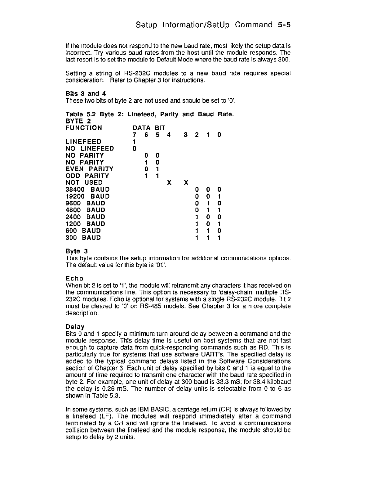
Setup Inforrnation/SetUp Command
If
the module does not respond
incorrect. Try various baud rates from the host until the module responds. The
last resort is to set the module to Default Mode where the baud rate is always
Setting a string of RS-232C modules to a new baud rate requires special
consideration. Refer
Bits
3
and
4
These two bits of byte 2 are not used and should be set
to
Chapter 3 for instructions.
to
the new baud rate,
most
likely the setup data is
to
'0,
5-5
300.
Table
BYTE
FUNCTION DATA BIT
LINEFEED
NO LINEFEED
NO PARITY
NO PARITY
EVEN
ODD PARITY
NOT USED
38400 BAUD
19200
9600
4800 BAUD
2400
1200
600
300 BAUD
Byte
This byte contains the setup information for additional communications options.
The default value for this byte is
Echo
When bit 2 is set
the communications line. This option
232C modules. Echo is optional for systems with a single
must be cleared
description.
5.2
2
PARITY
BAUD
BAUD
BAUD
BAUD
BAUD
3
Byte
2:
Linefeed, Parity
7654
and
Baud Rate.
3210
1
0
00
10
01
11
xx
000
001
010
011
100
101
I10
111
'01'.
to
'l',
the module will retransmit any characters it has received on
is
necessary to 'daisy-chain' multiple
to
'0'
on
RS-485
RS-232C
models. See Chapter 3 for a more complete
module. Bit
RS-
2
Delay
Bits 0 and I specify a minimum turn-around delay between a command and the
module response. This delay time
enough
particularly true for systems that use software
added
section of Chapter
amount of time required to transmit one character with the baud rate specified in
byte
the delay is
shown
In some systems, such as
a linefeed
terminated by a CR and will ignore the linefeed.
collision between the linefeed and the module response, the module should be
setup
to
capture data from quick-responding commands such as
to
the typical command delays listed in the Software Considerations
3.
Each unit
2.
For
example, one unit of delay at
0.26
mS. The number of delay units is selectable from
in
Table
5.3.
IBM
(LF).
The modules
to
delay by 2 units.
is
useful
on
host systems that are not
RD.
UART's.
of
delay specified by bits 0 and 1 is equal to the
300
baud is 33.3 mS; for
BASIC,
a carriage return
will
respond immediately after a command
The specified delay is
38.4
(CR)
is always followed by
To
avoid a communications
fast
This
kilobaud
0
to
6
is
as
Page 50

5-6
1700
USERS
MANUAL
Table
BYTE
FUNCTION
NOT
NO
ECHO
NO
2
4
6
Byte
Event Counter
The M1711M712 contains a programmable digital filter
of the Event Counter. The filter is particularly useful when the Event Counter is
used to count transitions from switches or other electro-mechanical contacts. The
filter will debounce noisy signals to provide error-free transition counting.
The filter constant is controIled by bits
shown in Table
This setting is ideal
noisy signals, filter constants of
the digital filter is described in Chapter 2.
Word
The M1700 command set is used by many Keithley MetraByte digital
devices, ranging from
DI,
setup is used to adjust the amount of
Mi700 device. One word of data
hexadecimal digits. The number
most appropriate for a specific device.
5.3
3
USED
ECHO
DELAYS
BYTE
BYTE
BYTE
4
Length
and
RA
Byte 3 Options.
DATA BIT
7654 3210
xxxx
x
0
1
00
TIME
TIME
TIME
DELAYS
DELAYS
DELAYS
Filter
4
and 5 of byte
5.4.
If
no fitter is selected, the Event Counter bandwidth is 20kHz.
for
electronic signals with clean transitions.
5,
20, and 50ms are available. The operation
1
to
64
I/O
lines. Many
commands operate on all of the data lines in paralIel. The word length
is
defined to be eight bits, represented by two
of
words required
of
the commands such as the
hex
bit data transmitted to and from
may
01
10
11
to
control the bandwidth
4.
The selections are
To
debounce
be adjusted to a value
of
I/O
DO,
the
1
The word length can vary from
of
0
is not allowed.
As
an example, a
would be: 31070102
The
'02'
indicates that the device
typical
Since the
the data length is incorrect, an error will be generaied:
The word length setup
DO
command to this unit would be:
Command:
Response:
Mi712
Command:
Response:
Command:
Response: *ABCD
Mi712
$1
DO1234
*
is setup for
$1
DO12345
?1
SYNTAX
also
$ID1
to 8 words, specified by bits
has
15
I/O
lines, and a typical setup for this device
is
setup for two words, or
two
words,
affects the parallel readback commands such as:
if
will accept the four digits of hex data.
ERROR
0-2.
A
16
bits
word length
of
data.
A
If
Page 51

Setup
Information/SetUp Command
5-7
Notice that with a word setup
same effect occurs with the
It
is possible
the physical 110 data width. For example, the M1712 may be setup with word
length
With this setup, the
Command:
Response:
The correct
to
setup a module with a word length that does not correspond with
=
'1'. Setup data
DO
argument is now
DI
command returns eight bits of data:
$1
'CD
=
DI
31
of
RA
0701
'2,
and
01
two
the
DI
command returns 2 words
RIV
commands.
hex digits:
of
data. The
Command: $1 DO34
Response:
A
word length of
device are used or
Regardless of the word setup, the rightmost hex digit
least significant 110 data. The most significant data is appended or truncated as
necessary corresponding to the word length setup.
It
is
also possible for the word length
the device. The M1712 may be setup with a word length of
*
'1'
may be appropriate for the
if
maximum communications speed is desired.
to
be greater than the physical data width
MI712
if
of
the bit data is always the
only
eight bits of the
'3':
3
10701
of
03
In this
case,
all
parallel data values must be 24 bits or
Command:
Response:
Command:
$1
DO123456
*
$1
DI
six
hex digits wide:
Response: *003456
The M1712 contains
of the
24
bits
will
most significant bits.
The deliberate use
streamlining host software. For example, in
devices, the host software may be simplified by standardizing
for alt devices.
The word length setup has
'Position' addressing.
15
110
lines. For the
be ignored. The
of
dummy data may seem wasteful, but it can be useful for
DI
no
affect on commands using single-bit 'Bit' or
DO
command, the most significant nine
command will return with
a
system with a mix
'0'
data for the nine
of
24 and
to
word length
15
bit
'3'
Page 52

5-8
1700
USERS
MANUAL
BYTE
FUN CTlON
NOT USED
NO FILTER
5ms
20ms
50ms
1
2
3
4
5
6
7
8
Setup
Until you become completely familiar with the Setup command, the best method
of changing setups is
change has been made correctly. Attempting
often lead
is
parameter at a time. Use the Read Setup
information currently in the module as a basis for creating a new setup.
example:
4
DATA BIT
7654
xx
00
01
10
11
WORD
WORDS
WORDS
WORDS
WORDS
WORDS
WORDS
WORDS
Hints
to
change one parameter at a time and
to
confusion.
to
reload the factory setup as shown in Table
If
you reach a state
3210
0001
0010
0011
0100
0101
0110
0111
1000
to
verify that the
to
modify all the setups
of
total confusion, the best recourse
5.5
and
try
again, changing one
(RS)
command
to
examine the setup
at
once can
For
Assume you have a
may be used in a daisy-chain (See Communications). Read out the current setup
with the Read Setup command:
Command:
Response:
By referring to Table
From the
hexadecimal representation of binary
to
'1'.
05.
changing only byte
RS
command we see that byte 3 is currently set
This results in binary
To perform the
Command:
Response:
Command:
Mi711
$1
*31070102
5.3,
SU
3:
$1
unit and you wish to set the unit
RS
we find that the echo is controlled by bit
0000
0000
command, use the data read out with the
WE
0101.
(SU
is
0001.
To
set
The new hexadecimal value
write-protected)
*
$lSU31070502
to
echo
so
that
2
of
byte
to
01.
This is the
echo, bit 2 must be
of
byte 3 is
RS
command,
3.
set
Response:
Verify that the module is echoing characters and the setup is correct.
By using the
problems associated with incorrect setups may be identified immediately. Once a
satisfactory setup has been developed, record the setup value and use it
configure similar modules.
If
you commit an error in using the Setup command,
communications with the module. In this case, it may be necessary to use the
DefauR Mode
RS
command and changing one setup parameter
to
re-establish communications.
at
it
is possibie
a
time, any
to
to
lose
it
Page 53

Setup Information/SetUp Command
5-9
Table
(All
Model Setup Message
MI711
M1712 31 0701
M1750 31 0701 03
M1770 31 0701
SlOaO
Setting up your
program provided in the 51000 software package. The
IBM
menu-driven operator interface which greatly simplifies the setup process and
decreases the chances
5.5
Factory
modules from the factory are set for address
31
Setups
0701
02
02
08
by
Model.
Software
MlOOO
Pc's
or compatibles and is free
module may be greatly simplified by using the setup
of
charge. The setup program provides a
of
setup errors.
'l',
300
baud, no panty)
SIOOO
software runs
on
Page 54

Chapter
5
Continuous Inputloutput
The
M1711/1712
communicate without being polled by a host computer. Collectively these modes
are called Continuous InpuVOutput Modes.
the host may be greatly simplified and in
altogether.
Continuous Output
A
M1711/1712
format as the response to a
‘1
D18000BO
modules may be setup in special modes which ailow them to
In
many appIications the burden on
some
cases the host may be eliminated
in continuous mode will produce an output string in the same
#1
DI
command:
Note that the output message contains the response prompt
address
continuous mode, a
command without actually receiving the command. The output data string may
triggered in one
Timer Mode:
Continuous Timer (CT) command. The CT command specifies a time period that
repeats indefinitely. After each timeout, the module will output the status data.
The module will periodically output the digital input data until the continuous
mode is disabled.
Edge-Trigger
it receives
produce an output in response
daisy-chaining several continuous output modules together.
Change Mode: In this mode the
the
Continuous Input
A
continuous-output module. The data string from a continuous output module is
interpreted as an output command by a continuous input module. This allows
data
without
(l),
the status of the digital
M1711/1712
of
three ways:
In
this mode, a software timer is activated in the module with the
Mode:
a
trigger signal
I/O
lines.
If
module setup for continuous input
to
be read
a
host computer.
In this mode the
on
the BOOlEV
a change is detected in status, an output data message is initiated.
at
one
module and replicated
110
module produces a response to a
M1711/1712
to
an external event.
M171111712
lines
(8000)
110
Pin. The edge trigger mode will
continuously monitors the status
will
respond
at
and a checksum
will output a data string when
It
also
to
the outputs of another module
(‘1,
the module
(BO).
In
#1Dl
be
provides a means
of
of
data produced by a
Continuous Input/Output Commands
The
MI
71 1
/I
71 2
modules contain several commands
modes. They are listed here for quick reference.
each command may be found in the Chapter
$ICMD
$1
CMT
$1
CME
$1
CMC
$1
CMI
Continuous Mode Disable
Enable Timer-Triggered Continuous
Enable Edge-Triggered Continuous Output Mode
Enable Change-Triggered Continuous Output Mode
Enable Continuous Input Mode
4.
to
setup the continuous
A
more complete description
Output
Mode
of
Page 55

6-2
1700
$1
$1
$1
$1CIA Specify Continuous Address
$1
Continuous Output Trigger Signal
In order to facilitate daisy-chaining of continuous output modules, each module
will produce an output trigger signal each time it completes an output data string.
The output trigger is
The Default
communications setup. This
Mode. However, when
momentarily becomes an output and produces a low-going trigger pulse. This
trigger pulse may be used to trigger another module set in Edge trigger mode. In
this manner, many modules may be daisy-chained together in continuous mode.
Applications
There is a wide variety
the continuous mode modules.
connection. However, a variety
usage.
USERS
RCM
CT Specify Continuous Timer value in seconds.
RCT Read Continuous Timer
RIA Read Continuous Input Address
pin is normally an input pin used
MANUAL
Read Continuous Mode Type.
Response is D, T,
Change
a
or
5
millisecond low pulse which appears
is
a
module produces a continuous output, the Default * pin
of
system configurations which may be implemented with
E, C or I for Disabled, Timer, Edge,
Input respectively.
on
to
place the module in a known
aIso true when a module is set for Continuous
It
would be impossible to detail every possible
of
examples will be given to demonstrate typical
the Default pin.
A)
Timer Mode (Figure
In
this configuration,
computer
obtain data. The host computer must have
proper operation.
For this example, we will setup the
commands are
I)
Setup the
communications
or
display device.
Command:
Response:
a
not
shown but necessary for write-protected commands).
Mi712
to
the host.
$1
1)
M1712
SU31070102
module is set to continuously output data to a host
It
is
not necessary for the host to poll the
MI712
as usual with the setup
to output data every
M1712
an
interrupt-driven serial input for
10
seconds.
(SU)
command for correct
to
(WE
Page 56

Continuous
Input/Output
6-3
2) Assign the
Command: $1
I/O
lines
of
AIOOOOO
the M1712 to be inputs:
Response:
3)
Set the Continuous Timer
(CT)
for
a 10 second interval:
Command: $1 CT+00010.00
Response:
This
tells
the
MI712
4)
Activate the continuous output with the Continuous Mode Timer
command. This will activate the continuous output data.
5)
Every
I0
seconds, the M1712 will read the status
status of those lines as
Response:
6)
The Continuous Mode may be disabled by the host by sending a Continuous
Mode Disable command:
to output data continuously in
if
it
was responding to
*ID1123482
a
#I
DI
10
second intervals
of
its
I/O
lines and output the
Command:
Command: $1 CMD
Response:
The CMD is not write-protected and a Write Enable
required.
*
(WE)
command is not
(CMT)
To
avoid communications collisions, the host
response, and then immediately issue the CMD command. In
example, the host has 10 seconds to issue the
of
a collision is remote.
even
if
the Continuous Timer
command immediately after the carriage return from the M1712
When the M1712 reads
temporarily halt the continuous mode output and look for an address character.
the MI712 detects its own address, it will
command. Otherwise it will resume the continuous mode output.
B)
Timer Mode With
This configuration is shown in Figure
with digital outputs.
outputs:
It
is
possible for the host
is
set for 0 seconds.
a
'$'or
'#'
character on the communications line, it will
Outputs
1.
For
example, the high-order 7 bits could be configured
should
read
However, this time the
wait
for
a continuous output
CMD
command,
to
disable the continuous mode
The
host
must issue the CMD
and process the rest of the
our
current
so
the likelihood
is
received.
M1712
is
setup
Command: $lAIOFFOO
Response:
Setup the Continuous Mode just like example
Command:
$ICT
+OOOiO.OO
A:
Response:
Command: $1CMT
Response:
*
If
as
The M1712 will continuously output the status
outputs, every 10 seconds.
of
the
I/O
lines, including the
Page 57

6-4
1700
USERS
MANUAL
However, with this setup, the host may respond with
commands
other control decision.
It
is
not necessary to disable the continuous mode before issuing the output
command. However,
should be timed
way to
immediately issue the output command.
Another method
Mode
acts normally and any
Mode may be resumed with a Continuous Mode Timer (CMT) command.
C)
Edge-Trigger
The M1712 may be triggered by an external digital signal which will command the
M1712
to
control the digitaI outputs in response to the input data or some
to
avoid communications collisions the
to
avoid the continuous response from the
do
fhis is to wait for a continuous output string from
of
performing output functions is to disable the Continuous
by
issuing a Continuous Mode Disable
of
the
I/O
commands may be performed. The Continuous
to
read the status
Mode
of
With
the
I/O
Host
lines and report the data (Figure
(CMD)
DO,
SB,
CB,
or other output
host
M1712.
the
module and then
command. The
command
The easiest
M1712
2).
now
The external trigger signal
BOO
the
application. The trigger input
will withstand a
switch by adding a pull-up resistor. (Figure
pin is used
for
0-30V
is
connected
the trigger, it
input without damage. The input may be triggered with a
is
designed
is
not available for general-purpose
to
the
SOO/EV
pin
of
the module. Since
I/O
to
accept a TTL-level signal, although
3)
in this
it
Page 58

300lEY
Continuous
InpuVOutput
6-5
The module
the MI
1)
Use
In this case the M1712 will be setup
Command:
Response:
2)
The
Other
application:
Command
Response:
This command assigns BOO through
outputs.
is
triggered on a positive-going edge to the
71
2
for edge-trigger mode:
the setup
(SU)
command to set the desired communications parameters.
for
$1
SU32070102
*
BOO
I/O
line must be assigned as an input to accept the trigger signal.
I/O
lines may be assigned as inputs
:
$2
A
I0
F
FOO
t
lYOK
B
BOOlEV
address
B07
'2':
or
outputs depending on the
as inputs, and
B08
through
pin.To setup
BOE
as
3)
The Continuous Timer (CT) command may be used
between the Trigger signal and the output data string. This feature is
some applications when multiple modules are tied together which will
illustrated in other examples. For this and most edge-trigger applications, set the
Continuous timer to
Command:
Response:
4)
Enable the edge trigger mode with the Continuous Mode Edge-trigger
command.
5)
When the M1712 senses a positive-going trigger on the BOOlEV line, it
perform the equivalent
Response:
6)
The host may terminate the edge-trigger mode with a Continuous Mode
Disable
collisions between the host command and responses from the module. The best
(CMD)
0
seconds:
$2CT+00000.00
of
a
#2DI
command and output the data:
*2DI123583
command. Precautions must be used
to
specify a delay time
useful
to
avoid communications
in
be
(CME)
wilt
Page 59

6-6
1700
USERS
MANUAL
method of disabling the continuous mode
CMD command:
Command:
Response: '2CMD30
The command is issued by the host and then the host looks for the correct
response string to be returned
detected, then the host knows that the continuous mode has been disabled.
the correct response string
command collided with response data from the module. The host simply repeats
the CMD command until the correct response
collisions are not harmful to
be able to accept framing errors and 'noise' characters gracefully when collisions
occur.
D) Continuous Output Daisy-Chain With
#2CMD
by
is
not received, it may be assumed that the CMD
RS485
is
to issue the 'long form' version of the
the
M1712. If
hardware. However, the host serial input must
the correct response string
is
obtained. Communications
Host
(Figure
4)
is
If
ADDRESS
EDGE
This configuration uses one module (address
trigger signal on the Default
set
for
Edge trigger mode. The third module (address
mode and receives its trigger signal from the Default
Additional edge-triggered modules may be implemented by connecting the
trigger output (Default
module in the series, and this connection may be repeated for any additional
modules.
123)
The net result
without the need for polling by the host. The data stream from this system would
typically
A
typical application will have 1 timer module with any number
of edge-triggered modules.
of
this connection
look
like this:
*)
of
*
line to trigger another module (address
a module
#3
is
a periodic burst of data from all the modules
1)
to the trigger input
#3
MODE
in Timer mode which produces a
3)
is
set-up
(BOO/EV)
ADDRESS
EDGE
MODE
for
edge-trigger
pin
of
module
#2
2)
which is
of
the next
(up
#2.
to
ADDRESS
TIER
MODE
#I
Page 60

Continuous
'1
Dl123482
*2D10001AA
'3DIFFFF02
Each data string is terminated by a carriage return. Note that the module address
to
is transmitted with the data
The easiest way of setting up a system like this is to install the modules and
operate them as a polled system first. Once the wiring and the operation
modules is established, the string may
all the Edge Triggered modules as described
setup the Timer module
Timer module must be long enough
time is too short, module
finished, resulting in a communications collision.
In
some cases, especially
the amount of data transmitted may overload the serial
this case, the data may be slowed down by specifying a finite amount of time in
the
Continuous Timer
trigger mode will delay the output data after
in CT.
The
host
may disable the continuous output data by sending a Continuous Mode
Disable command
to
the timer module:
easily determine the origin
be
set for Continuous Mode. First, set
in
Example
as
described in Example
to
allow all the modules to respond.
#I
will start
if
a large number of modules are connected in a string,
(CT)
of each edge-triggered module. A module in Edge
to
A.
The CT time specified in the
output data before module
it
is triggered by the amount specified
Input/Output 6-7
of
the data.
C.
The last step
port
buffer of the
of
all
is
If
the CT
#3
host.
the
up
to
has
In
Command:
Response:
The host should repeat the
timer mode is disabled, the string of modules may be polled by the host.
to continuous output operation, enable the continuous
module:
Command:
Response:
E)
Change Mode (Figure
A
MI712
digital input lines has changed state. The module
reporting the new state
module set up for change mode will output a data string
HOST
#1
CMD
*fCMD2F
CMD
$1
CMT
*
5)
GND
of
the inputs.
until the proper response is obtained. After the
I
-
-
DATA
DATA'
GND
mode
will
output the data string
of the Timer
if
To
one
return
of
its
To setup the
Assign the desired
M1712
for change mode:
I/O
lines to inputs:
Page 61

6-8
1700
USERS
MANUAL
Command:
$1
AIOOOFF
Response:
Note that not all lines are required to be inputs. In this example, digitaI
BOO-BO7
For
Set
The
state.
After the response
The host may disable the continuous output mode by sending
are set
this example, set the Continuous Timer
Command:
Response:
the module
Command:
Response:
M1712
If a change
*I
DlOl
Command:
Response:
to
outputs and
$1
CT+OOOOO.OO
608-BOE
are set
*
to
Continuous Mode:
$1
CMC
*
will continually scan the Digital
is
found, the new state of the I/O lines is reported
FFDS
is
transmitted, the
#I
CMD
*1CMD2F
M1712
to
inputs.
to
zero:
110
lines
to
detect any changes of
will resume scanning the
a
CMD command:
to
the host:
110
I/O
lines.
lines
The module may now be interrogated with the normal command -response
sequence. This method is useful when the host is required
to
response
lines (in this case 600-607) with normal
is completed, the
command.
The change mode is ideal in applications where the state
expected
alarm switches,
host computer. By using a
change in input status on
scanning inputs that are static.
a change in the input status. The host may control the digital output
I10
commands. After the control function
M1712
to
change infrequently. Inputs such as security switches, fire detectors,
etc.
may be returned
are not expected
Mi712
in change mode, the host may be alerted to a
an
interrupt basis thereby saving computer time
to
Continuous Mode with the CMC
to
change but must be detected by the
to
produce an output
of
the digital inputs is
Page 62

F)
Change
Mode
With Multiple
Continuous
Modules: (Figure
Input/Output
6)
6-9
It is possible to configure
mode on the same serial
This configuration may be used
one drawback to this connection is that there is no means of avoiding a
communications collision
exactly the same time. This
considerations aside, this type
guidelines are adhered
1)
The inputs being scanned are primarily static. This is usually the case when
monitoring security and alarm type
indicates an extraordinary event. This
would
occur
at the same time.
2)
Checksums and parity must be used
by data collisions.
3)
The host input
evidence that a change in input status has occurred. This wilI cover the unlikely
possibility that
the
host
may disable the Continuous Mode and poll the modules directly to read
the input lines.
4)
Use the highest baud rate possible to reduce the likelihood of collisions.
5)
The Continuous Timer may be used
particularly useful
causing a continuous stream of data from one module. The CT command may be
used to set a 'dead time' after
port
two
modules are responding at exactly the same time. In this case
if
two
or mode modules
fo
port.
to
extend the number of inputs monitored. The
if
two modules attempt to output data messages at
will
result in communications errors. Theoretical
of
connection may be very useful
to:
of
inputs where the change of an input
cuts
down the likelihood that two events
to
detect communications errors caused
should
an input is likely to turn on and
be
setup
so
that any activity
to
limit responses from a module. This
a
module has produced an output response:
Continuous Output Change
if
the following
on
the input lines
off
quickly and constantly,
is
Command:
Response:
With the Continuous Timer set
after each response before resuming scanning the digital
$1
CT+00005.00
*
to 5 seconds, module
#1
will pause for 5 seconds
110
lines. This prevents
Page 63

6-10
1700
USERS
MANUAL
the module from hogging the communications bus in response to continuously
changing input lines.
G)
Continuous Input
The M1711/1712 modules may be
Mode
set
to
a special mode called Continuous Input
Mode which allows the module to respond to data transmitted by another module.
A
module in Continuous Input Mode may be paired with a module in Continuous
Output Mode to provide digital data transfer without
a
supervisory host. Figure
6
shows the simpIest connection.
(Figure 7)
Module
A.
Module
CONTINUOUS
OUTPUT
TIM3
MODE
#1
is setup in Continuous Output Timer Mode as described in Example
#1
will read the state of the digital inputs and produce data messages
CONTINUOUS
IN PUT
IN PUT
ADDRESS
4
on the communications bus. In this application, setting the Continuous Timer to
zero will produce the fastest response to input changes.
Module
are assigned as outputs. In continuous input mode, module
#2
is setup
for
Continuous Input Mode. The digital
I/O
lines
of
#2
will use the data
module
#2
from module #1 as a command to control the digital outputs. The net effect is that
the outputs of module
For example, an output message from module #1 might
*1
DIAOA059 (59
Module
#2
in Continuous Input mode will interpret this data as a Digital Output
#2
are controtled directly by the inputs of module
look
like:
is
checksum}
#l.
command. Internally, the continuous input module will translate fhis data and
perform the same function as:
$1
DOSFSFAD (AD
is
checksum)
I
Note that the original data
that a high input
at
module
the state of the digital inputs on module
module
#2.
'AOAO'
is complemented
#1
appears as a high output at module
#1
to
'5F5F'. This is necessary
is recreated at the digital outputs of
#2.
As
a result,
so
Since module #1 is continually outputting data on the communications lines, any
of
changes in the state
module
To setup module
#2
and the output lines will change to reflect the new state.
#2
the digital inputs on module
for Continuous Input Mode:
#1
will be transmitted
to
Page 64

Continuous
1)
Setup the module for an address different from the Continuous Output
In
module.
The Continuous Input module will be setup for address
this example, the Continuous Output module is setup for address '1'.
InpuVOutput
'2':
6-1
1
Command:
Response:
Any address may be used for the Continuous Input module as
different from module
The communications setups for
with identical baud rate and panty settings. Also, the word length setup must be
identical.
2)
Assign the digital
Command:
Response:
3)
The Continuous Input module must
(CIA). This address
address is necessary
data
on
the communications bus. The full purpose
demonstrated in the next few examples. In this case, module
respond to data from module #l. Character
Input Address:
Com m and
Response:
The input address '31' is stored in nonvolatile memory.
the Read Input Address command:
$1
SU32070102
*
#I.
I/O
lines to be outputs:
$ZAIOFFFF
*
is
different from the normal communications address. This
so
that the continuous input module may selectively read
:
$2
Ct A3
*
1
both
modules must match. They must
be
assigned a Continuous Input Address
of
'1'
or
ASCII '31' is
It
can be read back with
long
as it is
be
setup
the CIA will be
#2
is setup to
the
Continuous
Command:
Response:
Enable the Continuous lnput Mode with the Continuous Mode Input
4)
command:
Command: $2CMI
Response:
The Continuous mode is saved in nonvolatile memory.
After the Continuous Input module has been setup, it may be connected to the
continuous output module as a stand-alone pair. Since all setup data is stored in
nonvolatile memory, the input-output pair will initialize automatically upon power-
up.
No
host is necessary for the continuous input-output function.
$2RIA
3
1
*
Page 65

6-12
H)
Figure 8 shows a system, with
two modules set
1700
Multiple Continuous Input/Output
USERS
for
MANUAL
two
Continuous Input Mode: (Figure
IN
PUSS
modules set for continuous output mode and
8)
OUTPUTS
CONTINUOUS
OUTPUT
This system is similar-to example E except that 2 input-output module pairs share
the same communications line. Modules
output as detailed in example
their respective digital
A
typical output data stream would be:
'lD1812386
*2DIAOAOCEl
Module
(CIA)
from module
will ignore the data
Module
(CIA)
communications
Therefore the outputs
up to
bus.
#3
is
set for Continuous Input mode with the Continuous Input Address
equal
to
ASCII
#1
#4
is set for Continuous Input mode and its Continuous
is equal to ASCII
124
pairs
110
'31'
and use the data
from
bus
and responds only
of
of
modules may be linked together on a single communications
B.
This pair
lines and output the data on the communications bus.
(86
is
(CB
is
or character
as
a command
module
module
'32'
#2.
or
character
#4
will follow the inputs
#I
and
#2
of
M1712's
are setup
constantly read the state of
for
continuous
checksum)
checksum)
'1'.
This module will pick off the output data
to
set its output lines. Module
Input
'2'.
It
examines the data on the
to
data containing the address
of
module
#2.
#3
Address
'2'.
In theory,
CONTINUOUS
INPUT
Page 66

I)
Bidirectional Continuous InputlOUtput
To
provide bidirectional data transfer from
pairs of modules and
OUTPUTS
two
communications links: (Figure
Continuous
one
location
Input/Output
to
another, simply use
9)
CONTINUOUS
IN
PUT
CIA=31
6-13
two
IN
PUTS
J)
Multiple Outputs
The output
than one continuous
Addresses
CONTINUOUS
OUTPUT
data
from a Continuous
(CIA): (Figure
CONTINUOUS
INPUT
CIA=
31
input
module
10)
CONTINUOUS
INPUT
CONTINUOUS
OUTPUT
Output
by
module
assigning the correct Continuous Input
may
be
used
to
control more
CONTINUOUS
IN
PUT
CONTINUOUS
INPUT
INPUTS
OUTPUTS
OUTPUTS
OUTPUTS
Page 67

6-14
1700
USERS
MANUAL
In this system, module
are setup for Continuous Input. The three Continuous Input modules are
setup with a Continuous Input Address (CIA) of ASCII 31 or character
means that each of these three modules
an output command. The outputs of modules
data of module
Continuous
A module in continuous input mode will respond to data in the form of:
*I
D180F096
This is typical
module. The
The Continuous Input Module will respond to
read data from module
which data strings will be examined
command
case, to allow the module to respond
a
co m m
nd
#1.
Input
of
'1'
denotes the address
is
used
:
Command:
Response:
The number
An important consideration in constructing
make sure that all modules tied to the communications bus have unique address
as specified by the
modules in a normal polled manner. This greatly simplifies setup and debugging.
The Continuous Input Addresses (CIA) may be
the polled address.
'31'
is the ASCII code
#I
is set for Continuous Output mode. Modules
will
accept the data from module
2,
3
and 4 will replicate the input
Protocol
a
data string that may
#1.
to specify the ASCII code for the address character. In this
$2ClA31
*
SU
command. This allows an intelligent host
Notes
be
produced by a continuous output
of
the module producing the data stream.
this
data only
The Continuous Input Address (CIA)
by
the Continuous Input module. The CIA
to
data with the address tag
for
character '1'.
a
continuous inpuUoutput system
set
to
if
it
any value independent
is programmed
is
2,
3
&
'1'.
This
#1
used to specify
'l',
use the
is
to
use
the
4
all
as
to
to
of
Page 68

Table
of
ASCll
characters
Hexadecimal (Hex), andBinary.Claret
(A) and
their equivalent values in
(*)
represents Control
Appendix
ASCII
Decimal
function.
(D),
A
Table
A
^@
"A
"B
^c
"D
"E
"F
"G
"H
"I
"J
"K
"L
"M
"N
"0
"P
"Q
"R
"S
"T
"U
nV
"W
"X
"Y
"Z
"1
"\
"I
M
A
-
!
#
$
%
&
(
1
+
i
0
1
Hex
D
0
00
1 01
2 02
3
03
4 04
5 05
06
6
7
07
8 08
9 09
10
OA
11 OB
oc
12
13
OD
14
OE
15
OF
16 10
17 11
18 12
19 13
20
14
21 15
22 16
23 17
24
18
25
19
26 1A
27 1B
28 1C
29 1D
30 1E
31 1F
32 20
33 21
22
34
35 23
36 24
37 25
38 26
39 27
40 28
41 29
42 2A
43 2B
44 2c
2D
45
46 2E
47 2F
48
30
49 31
Binary
00000000
00000001
0000001
0000001
000001
00000101
000001 10
000001 11
00001000
00001001
00001 010
0000101 1
00001 100
00001 101
00001 110
00001
0001
0001 0001
0001 0010
0001 001
0001 01
0001 01 01
0001 01 10
0001 01 11
0001 1000
0001 1001
00011010
00011011
00011100
0001 11 01
0001 11
000111 11
001
001 00001
001
00100011
001 001
001 001 01
00100110
00100111
001 01
00
101
00101 01
00101011
001 01 100
001 01 101
00101 110
00101 111
001 10000
001 10001
0
1
00
I1
1
0000
1
00
10
00000
00010
00
000
00
1
0
D
128 80
129 81 10000001
130 82 10000010
131 83
132 84 10000100
133 85 f0000101
134
135 87 10000111
136 88
137 89 10001001
138 8A 10001010
139 88 10001011
140 8C 10001100
141 8D
142 8E
143
144 90
145 91 10010001
146 92 10010010
147
148 94 10010100
149 95 10010101
150 96 10010110
151
152
153 99 10011001
154 9A 10011010
155
156 9C 10011100
157
158 9E 10011110
159 9F 10011111
160 A0 10100000
161 A1 10100001
162 A2 10100010
163 A3 10100011
164
165 A5 10100101
166 A6 10100110
167 A7
168 AS 10101000
169 A9 10101001
170 AA 10101010
171 AB
172 AC 10101100
173 AD
174
175
176
177 B1 10110001
Hex Binary
10000000
I0000011
86
10000110
10001000
10001101
10001110
8F
10001111
10010000
93 10010011
97 10010111
98
10011000
9B 10011011
9D 10011101
A4 10100100
10100111
10101011
10101101
AE
10101110
10101111
AF
BO
10110000
Page 69

A-2
1700
A
D
2
50 32 00110010
51
3
4
52 34 00110100
5
53
6
54 36 00110110
7
55
8
56 38 00111000
9
57 39 00111001
58 3A 00111010
59 3B 00111011
<
60
-
-
61 3D 00111101
>
62 3E 00111110
?
63 3F 001111fl
64
0
A
65
B
66 42 01000010
C
67 43 01000011
D
68 44 01000100
E
69 45 01000101
F
70 46 01000110
G
71 47 01000111
H
72 48 01001000
I
73
74 4A 01001010
J
K
75 4B 01001011
L
76 4C 0~001100
M
77 4D 01001101
N
78 4E 01001110
79 4F 01001111
0
P
80
Q
81
R
82 52 01010010
S
83 53 0~010011
T
84
U
85
V
86
W
a7
X
88 58 01011000
Y
89 59 01011001
Z
90
91
I
\
92 5C 01011100
93
I
94
95 5F 01011111
-
96
a
97 61 01100001
b
98 62 01100010
c
99 63 01100011
100 64 01100100
d
101 65 01100101
e
f
102 66 01100110
103 67 01100111
9
h
104 68 01101000
i
105 69 01101001
106
j
USERS
Hex
Binary
33
00110011
35 00110101
37 00110111
3C 00111100
40 01000000
41 01000001
49 01001001
50
0<010000
51
01010001
54
01010100
55
01010101
56
01010110
57
oioioi11
5A
01011010
5B
01011011
5D 01011101
5E
010111f0
60
01100000
6A
01101010
MANUAL
D
178
179
180 B4 10110100
181
182
183 B7
184 B8 10111000
185 ~9
186 BA 10111010
187 BB
188
189 BD 10111101
190 BE 10111110
191
192 CO 11000000
193 C1 11000001
194
195
196
197
198 C6 llOOOflO
199 c7 11000111
200 C8 11001000
201 c9 11001001
202 CA 11001010
203 CB 11001011
204 CC 11001<00
205
206
207
208 DO 11010000
209 D1
210 D2 11010010
211
212
213
214
215 D7
216
217 D9 11011001
218 DA
219 DB
220
221
222 DE 11011110
223 DF
224 EO 11f00000
225 El 11100001
226
227
228
229
230
231 E7
232 E8 11101000
233
234 EA 11101010
Hex
Binary
B2 10110010
B3 10110011
B5 10110101
B6 10110110
10110111
ioiiiooi
10111011
BC 10111100
BF 10111111
C2
11000010
C3 11000011
C4
11000100
C5
11000~01
CD 11001~01
CE
11001410
CF 11001.111
11010001
D3 11010011
D4 11010100
D5 11010~01
D6
11010110
11010111
D8 11011000
11011010
11011011
DC 11011100
DD 11011101
11011111
11100010
E2
E3 11100011
E4 11100100
E5
11100101
E6
11100110
11100111
E9 11101001
Page 70

A
D
Hex
k
107
6B 01101011
1
108
6C
rn
109
6D
n
110
6E
o
111
6F
p
112 70 01110000
q
113
71
r
114 72
s
115
73
t
116 74
u
117
75
v
118
76 01110110
w
119
77
x
120 78 o1iiiaoo
y
121 79 01111001
z
122
7A
{
123 7B 01111011
I
124 7C 01111100
}
125
7D 01111101
-
126 7E 01111110
127 7F 01111111
Binary
01101100
01101101
01101110
01101111
01110001
01110010
01110011
01110100
01110101
01110111
01111010
ASCII
Hex
D
235
236
237
238
239
240
241
242
243
244 F4
245
246
247 F7 11110111
248
249
250
251
252
253
254 FE 11111110
255
Binary
11101011
EB
EC
11101100
11101101
ED
11101110
EE
EF
11101111
FO
11110000
F1
11110001
F2
11110010
F3 11110011
11110100
F5 11110101
F6
11110110
F8
11111000
F9
11111001
11111010
FA
FB 11111011
FC
11111100
FD
11111101
FF
11111111
Table
A-3
Page 71

M1770
64
Channel
Appendix
Digital
I/O
B
Board
The Mi770 Digital
capability for computers, modems, and other devices with standard serial
ports. Commands communicated over standard RS-232 or RS-485 links
may be used
The Mi 700 is designed
relay racks. Up
with ribbon cable connectors.
The
64
combination designated by the user. The inputloutput configuration may
be changed at any time through the communications port. The
assignments are saved in nonvolatile memory and are autornaticly loaded
when the unit is powered up.
Getting
RS-232,
The MI770 contains drivers
ports. The M1770 must be configured
connected to the host. The M1770 has a 12-pin header near the edge of the
board marked
make sure the three jumpers are installed adjacent
To configure the board for RS-485, make sure the jumpers are adjacent
to
the RS-485 label.
Pin
Connections
The host interface connection is wired
to
I/O
channels may be configured to be inputs or outputs in any
Started
RS-485
I/O
interface is designed
control
to four 16-channel racks may be connected
RS-232/RS-485.
or
read up
to interface to industry-standard solid-state
Selection
to
to
connect
To
64 digital
to
to
the desired interface before
configure the board for RS-232,
to
the six-pin terminal plug:
to
provide remote
I/O
channels.
either RS-232
to
the RS-232 label.
to
the M1770
or
RS-485
110
I/O
it
is
:
Pin 1
supply must provide
Pin 2:
When grounded, the board assumes the default communications setup of
300
Pin
configured for RS-485, this pin is the DATA connection.
3
Pin 4:
configured for RS-485, this is the DATA*,
connection.
Pin
grounded, the M1770 will be in Continuous Mode.
Pin
signal ground for the serial port.
Output Connections
The digital
connectors. The output connections are made
industry-standard 16-channel solid-state relay racks. The connector
nearest the edge of the board (J2) is wired
+5V
This
is
the power supply connection for the board. The power
+5V
+/-
5% at
DEFAULT' This pin
baud, any address, no parity (See Chapter 1).
3:
DATA/TX This pin
is
the
Transmit output from the M1770.
DATA*/RX This pin is a serial port connection.
For
RS-232, this
5:
CONT'
6:
GND This is the power supply ground connection.
This pin is normally
I/O
connections are made through
is
is
is
100
mA.
normally left open
a serial port connection.
the receive input of the M1770.
Ieft
open or pulled up to
to
the lowest-order
or
pulled high
If
the board is
For
RS-232,
If
the board
or
the negative data
+5V.
It
is also the
the
four ribbon cable
to
be compatable with
16
to
When
bits.
+5V.
pin
is
Page 72

B-2
1700
52
-
Pin Sianal
17
I9
21
23
25
27
USERS
BOF
BOE
BOD
BOC
BOB
BOA
29 B09
31
33
35
37
39
41
43
45
47
All
even
All
pins are
other
pins
BOB
B07
B06
B05
B04
B03
B02
B01
BOO
connected
are
no connection.
MANUAL
to
GND
53
-
Pin
17
19
21
23
25
27
29
31
33 B17
35 B16
37
39
41 B13
43 BIZ
45 B11
47
All
even
pins are
All
other pins
Sianal
B1
F
B1
E
B1
D
B1
C
B1
B
B1
A
B19
B18
B15
01
4
BIO
connected
are
no connection.
to
GND
Page 73

H1770
J4
-
Pin
17
19 B2E
21
23 B2C
25 B23
27
29 B29
31 B28
33 827
35 B26
37 B25
39 B24
41 B23
43 822
45 B21
47 820
Even
pins
All
other pins are no connection.
Siand
B2
B2D
B2A
18-50
F
are connected
64
Channel
to
GND
Digital
I/O
Board
B-3
J5
-
Pin
17
19 B3E
21 B3D
23
25 B3B
27 B3A
29 B39
31
33 837
35 B36
37
39
41 B33
43
45
47 B30
Even
pins
All
other
Sianal
83
F
B3C
B38
B35
834
B32
83
1
18-50
pins
are connected
are no connection.
to
GND
Page 74

M1750
The
Mi750
Opto-22
with
the
Hook-Up:
Plug
the
the header and latch the board
is designed
16
or
24
channel solid-state relay backplane or equivalent backplanes
standard pin-out.
M1750
into the backplane header. Be sure the board is centered over
to
interface directly
24-Channel
to
the header.
to
an
MSS-16
Appendix
Digital
I/O
IlO
Board
module rack
C
or
M1750
The
desired communications link with the three shorting bars near the edge
M1750.
Move the three shunts
If
RS-232
output pin. The DATA'/RX pin is the receive input.
If
RS-485
Data' (Data
The
M1750
the
GND
should be
110
lines are connected
The odd-numbered pins
pad being
contains line drivers
Move the fhree shunts to the
to
the
is
selected, the DATMX pin on the 6-pin connector is the transmit
is
selected, connect the Data (Data
-)
line
to
the DATA*/RX pin.
is powered by a regulated
and
+5
Vdc
pins. For proper operation, relays used in a backplane
+5V
types.
to
the odd-numbered pins on the header connector.
are
#I.
All
even-numbered pins are connected
for
both
RS-232
'RS-232'
'RS-485'
closest to the edge
position
c)
4.75
to
to
line to the DATMX pin and the
5.5V
and
RS-485.
position
select
power supply connected to
of
the board with the square
to
RS-485.
to
ground.
Select the
select
RS-232.
of
the
Page 75

Specifications are subject to change without notice.
All Keithley trademarks and trade names are the property of Keithley Instruments, Inc. All other
trademarks and trade names are the property of their respective companies.
Keithley Instruments, Inc. 28775 Aurora Road • Cleveland, Ohio 44139 • 440-248-0400 • Fax: 440-248-6168
1-888-KEITHLEY (534-8453) • www.keithley.com
Sales Offices: BELGIUM: Bergensesteenweg 709 • B-1600 Sint-Pieters-Leeuw • 02-363 00 40 • Fax: 02/363 00 64
CHINA: Yuan Chen Xin Building, Room 705 • 12 Yumin Road, Dewai, Madian • Beijing 100029 • 8610-6202-2886 • Fax: 8610-6202-2892
FINLAND: Tietäjäntie 2 • 02130 Espoo • Phone: 09-54 75 08 10 • Fax: 09-25 10 51 00
FRANCE: 3, allée des Garays • 91127 Palaiseau Cédex • 01-64 53 20 20 • Fax: 01-60 11 77 26
GERMANY: Landsberger Strasse 65 • 82110 Germering • 089/84 93 07-40 • Fax: 089/84 93 07-34
GREAT BRITAIN: Unit 2 Commerce Park, Brunel Road • Theale • Berkshire RG7 4AB • 0118 929 7500 • Fax: 0118 929 7519
INDIA: Flat 2B, Willocrissa • 14, Rest House Crescent • Bangalore 560 001 • 91-80-509-1320/21 • Fax: 91-80-509-1322
ITALY: Viale San Gimignano, 38 • 20146 Milano • 02-48 39 16 01 • Fax: 02-48 30 22 74
JAPAN: New Pier Takeshiba North Tower 13F • 11-1, Kaigan 1-chome • Minato-ku, Tokyo 105-0022 • 81-3-5733-7555 • Fax: 81-3-5733-7556
KOREA: 2FL., URI Building • 2-14 Yangjae-Dong • Seocho-Gu, Seoul 137-888 • 82-2-574-7778 • Fax: 82-2-574-7838
NETHERLANDS: Postbus 559 • 4200 AN Gorinchem • 0183-635333 • Fax: 0183-630821
SWEDEN: c/o Regus Business Centre • Frosundaviks Allé 15, 4tr • 169 70 Solna • 08-509 04 679 • Fax: 08-655 26 10
SWITZERLAND: Kriesbachstrasse 4 • 8600 Dübendorf • 01-821 94 44 • Fax: 01-820 30 81
TAIWAN: 1FL., 85 Po Ai Street • Hsinchu, Taiwan, R.O.C. • 886-3-572-9077• Fax: 886-3-572-9031
© Copyright 2001 Keithley Instruments, Inc.
Printed in the U.S.A.
4/02
 Loading...