

Page 1

LPD64
6 Series Low Profile Digitizer
Installation and Safety Manual
*P071365900*
071365900
Page 2

Page 3

LPD64
6 Series Low Profile Digitizer
Installation and Safety Manual
Supports Product Firmware V1.20.x and above.
www.tek.com
071365900
Page 4

Copyright © Tektronix. All rights reserved. Licensed software products are owned by Tektronix or its subsidiaries or suppliers, and are
protected by national copyright laws and international treaty provisions. Tektronix products are covered by U.S. and foreign patents, issued
and pending. Information in this publication supersedes that in all previously published material. Specifications and price change privileges
reserved.
TEKTRONIX and TEK are registered trademarks of Tektronix, Inc.
Contacting Tektronix
Tektronix, Inc.
14150 SW Karl Braun Drive
P.O. Box 500
Beaverton, OR 97077
USA
For product information, sales, service, and technical support:
■
In North America, call 1-800-833-9200.
■
Worldwide, visit www.tek.com to find contacts in your area.
Page 5

Table of Contents
Important safety information ................................................................................................................................ iii
General safety summary ................................................................................................................................ iii
Service safety summary ................................................................................................................................. v
Terms in the manual ...................................................................................................................................... vi
Terms on the product .................................................................................................................................... vi
Symbols on the product ................................................................................................................................. vi
Preface ............................................................................................................................................................... vii
Key features .................................................................................................................................................. vii
Related documents ...................................................................................................................................... viii
Installing your instrument
Check shipped accessories ........................................................................................................................... 1
Operating requirements ................................................................................................................................. 1
Input signal requirements ............................................................................................................................... 2
Installing the instrument in a rack ................................................................................................................... 2
Secure (lock) the instrument .......................................................................................................................... 4
Powering the instrument ................................................................................................................................ 4
Check that the instrument passes power-on self tests ................................................................................... 5
Connecting signals to the instrument ............................................................................................................. 5
Getting acquainted with your instrument
Front panel controls and connections, LPD64 ............................................................................................... 7
Rear panel connections ................................................................................................................................. 8
M.2 drive access ............................................................................................................................................ 9
The graphical user interface ......................................................................................................................... 10
Configure the instrument
Set the time zone and clock readout format ................................................................................................. 11
Download and install the latest instrument firmware .................................................................................... 12
Run Signal Path Compensation (SPC) ........................................................................................................ 13
Connect to a network (LAN) ......................................................................................................................... 13
Remote access from a Web browser (standard instrument) ........................................................................ 14
Operating basics
Operating basics ......................................................................................................................................... 17
LPD64 Installation and Safety Manual
i
Page 6

Table of Contents
Maintenance
Maintenance ................................................................................................................................................. 19
Cleaning ....................................................................................................................................................... 19
Performance verification interval and adjustment ........................................................................................ 19
Replaceable parts list ................................................................................................................................... 19
EMC Safety and environmental compliance
Compliance Information ............................................................................................................................... 23
EMC compliance .................................................................................................................................... 23
Safety compliance .................................................................................................................................. 24
Environmental compliance ..................................................................................................................... 25
ii LPD64 Installation and Safety Manual
Page 7

Important safety information
This manual contains information and warnings that must be followed by the user for safe operation and to keep the product in a
safe condition.
To safely perform service on this product, see the Service safety summary that follows the General safety summary.
General safety summary
Use the product only as specified. Review the following safety precautions to avoid injury and prevent damage to this product or
any products connected to it. Carefully read all instructions. Retain these instructions for future reference.
This product shall be used in accordance with local and national codes.
For correct and safe operation of the product, it is essential that you follow generally accepted safety procedures in addition to
the safety precautions specified in this manual.
The product is designed to be used by trained personnel only.
Only qualified personnel who are aware of the hazards involved should remove the cover for repair, maintenance, or adjustment.
Before use, always check the product with a known source to be sure it is operating correctly.
This product is not intended for detection of hazardous voltages.
Use personal protective equipment to prevent shock and arc blast injury where hazardous live conductors are exposed.
While using this product, you may need to access other parts of a larger system. Read the safety sections of the other
component manuals for warnings and cautions related to operating the system.
When incorporating this equipment into a system, the safety of that system is the responsibility of the assembler of the system.
To avoid fire or personal injury
Use proper power cord. Use only the power cord specified for this product and certified for the country of use. Do not use the
provided power cord for other products.
Ground the product. This product is grounded through the grounding conductor of the power cord. To avoid electric shock, the
grounding conductor must be connected to earth ground. Before making connections to the input or output terminals of the
product, ensure that the product is properly grounded. Do not disable the power cord grounding connection.
Power disconnect. The power cord disconnects the product from the power source. See instructions for the location. Do not
position the equipment so that it is difficult to operate the power cord; it must remain accessible to the user at all times to allow for
quick disconnection if needed.
Connect and disconnect properly. Do not connect or disconnect probes or test leads while they are connected to a voltage
source. Use only insulated voltage probes, test leads, and adapters supplied with the product, or indicated by Tektronix to be
suitable for the product.
Observe all terminal ratings. To avoid fire or shock hazard, observe all rating and markings on the product. Consult the product
manual for further ratings information before making connections to the product. Do not exceed the Measurement Category
(CAT) rating and voltage or current rating of the lowest rated individual component of a product, probe, or accessory. Use caution
when using 1:1 test leads because the probe tip voltage is directly transmitted to the product.
Do not apply a potential to any terminal, including the common terminal, that exceeds the maximum rating of that terminal.
Do not float the common terminal above the rated voltage for that terminal.
The measurement terminals on this product are not rated for connection to mains or Category II, III, or IV circuits.
LPD64 Installation and Safety Manual
iii
Page 8
Important safety information
Do not operate without covers. Do not operate this product with covers or panels removed, or with the case open. Hazardous
voltage exposure is possible.
Avoid exposed circuitry. Do not touch exposed connections and components when power is present.
Do not operate with suspected failures. If you suspect that there is damage to this product, have it inspected by qualified
service personnel.
Disable the product if it is damaged. Do not use the product if it is damaged or operates incorrectly. If in doubt about safety of the
product, turn it off and disconnect the power cord. Clearly mark the product to prevent its further operation.
Before use, inspect voltage probes, test leads, and accessories for mechanical damage and replace when damaged. Do not use
probes or test leads if they are damaged, if there is exposed metal, or if a wear indicator shows.
Examine the exterior of the product before you use it. Look for cracks or missing pieces.
Use only specified replacement parts.
Do not operate in wet/damp conditions. Be aware that condensation may occur if a unit is moved from a cold to a warm
environment.
Do not operate in an explosive atmosphere.
Keep product surfaces clean and dry. Remove the input signals before you clean the product.
Provide proper ventilation. Refer to the installation instructions in the manual for details on installing the product so it has
proper ventilation.
Slots and openings are provided for ventilation and should never be covered or otherwise obstructed. Do not push objects into
any of the openings.
Provide a safe working environment. Always place the product in a location convenient for viewing the display and indicators.
Avoid improper or prolonged use of keyboards, pointers, and button pads. Improper or prolonged keyboard or pointer use may
result in serious injury.
Be sure your work area meets applicable ergonomic standards. Consult with an ergonomics professional to avoid stress injuries.
Use care when lifting and carrying the product. This product is provided with a handle or handles for lifting and carrying.
WARNING. The product is heavy. To reduce the risk of personal injury or damage to the device get help when lifting or carrying
the product.
Use only the Tektronix rackmount hardware specified for this product.
iv LPD64 Installation and Safety Manual
Page 9

Important safety information
Probes and test leads
Before connecting probes or test leads, connect the power cord from the power connector to a properly grounded power outlet.
Keep fingers behind the protective barrier, protective finger guard, or tactile indicator on the probes.
Remove all probes, test leads and accessories that are not in use.
Use only correct Measurement Category (CAT), voltage, temperature, altitude, and amperage rated probes, test leads, and
adapters for any measurement.
Beware of high voltages. Understand the voltage ratings for the probe you are using and do not exceed those ratings. Two
ratings are important to know and understand:
■
The maximum measurement voltage from the probe tip to the probe reference lead
■
The maximum floating voltage from the probe reference lead to earth ground
These two voltage ratings depend on the probe and your application. Refer to the Specifications section of the manual for more
information.
WARNING. To prevent electrical shock, do not exceed the maximum measurement or maximum floating voltage for the
oscilloscope input BNC connector, probe tip, or probe reference lead.
Connect and disconnect properly. Connect the probe output to the measurement product before connecting the probe to the
circuit under test. Connect the probe reference lead to the circuit under test before connecting the probe input. Disconnect the
probe input and the probe reference lead from the circuit under test before disconnecting the probe from the measurement
product.
Connect the probe reference lead to earth ground only.
Inspect the probe and accessories. Before each use, inspect probe and accessories for damage (cuts, tears, or defects in the
probe body, accessories, or cable jacket). Do not use if damaged.
Ground-referenced oscilloscope use. Do not float the reference lead of this probe when using with ground-referenced
oscilloscopes. The reference lead must be connected to earth potential (0 V).
Floating measurement use. Do not float the reference lead of this probe above the rated float voltage.
Risk assessment warnings and information
Service safety summary
The Service safety summary section contains additional information required to safely perform service on the product. Only
qualified personnel should perform service procedures. Read this Service safety summary and the General safety summary
before performing any service procedures.
To avoid electric shock. Do not touch exposed connections.
Do not service alone. Do not perform internal service or adjustments of this product unless another person capable of rendering
first aid and resuscitation is present.
Disconnect power. To avoid electric shock, switch off the product power and disconnect the power cord from the mains power
before removing any covers or panels, or opening the case for servicing.
Use care when servicing with power on. Dangerous voltages or currents may exist in this product. Disconnect power, remove
battery (if applicable), and disconnect test leads before removing protective panels, soldering, or replacing components.
Verify safety after repair. Always recheck ground continuity and mains dielectric strength after performing a repair.
LPD64 Installation and Safety Manual v
Page 10
Important safety information
Terms in the manual
These terms may appear in this manual:
WARNING. Warning statements identify conditions or practices that could result in injury or loss of life.
CAUTION. Caution statements identify conditions or practices that could result in damage to this product or other property.
Terms on the product
These terms may appear on the product:
■
DANGER indicates an injury hazard immediately accessible as you read the marking.
■
WARNING indicates an injury hazard not immediately accessible as you read the marking.
■
CAUTION indicates a hazard to property including the product.
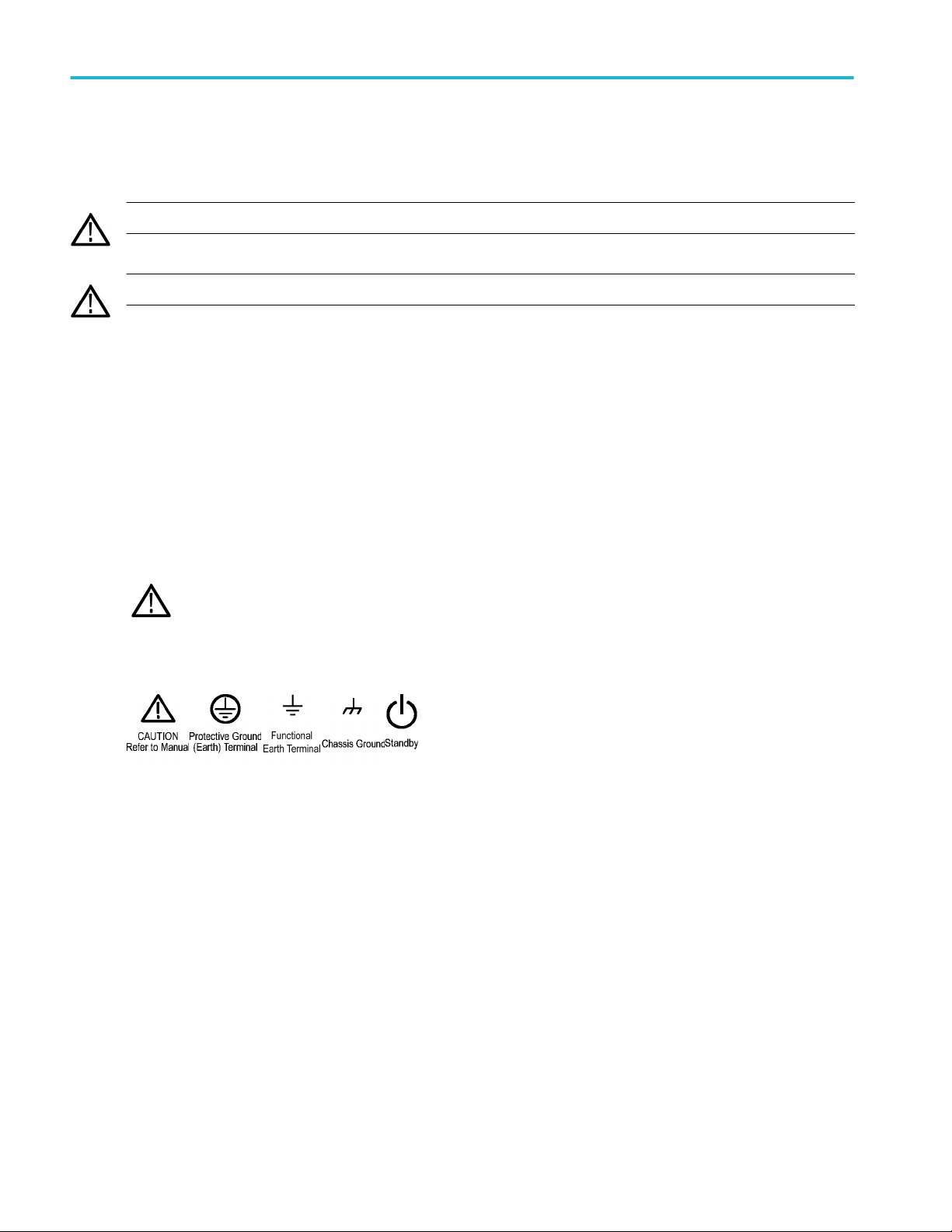
Symbols on the product
When this symbol is marked on the product, be sure to consult the manual to find out the nature of the potential
hazards and any actions which have to be taken to avoid them. (This symbol may also be used to refer the user to
ratings in the manual.)
The following symbols may appear on the product:
vi LPD64 Installation and Safety Manual
Page 11

Preface
This manual provides product safety and compliance, how to connect and power on the instrument, and an introduction to the
instrument features, controls and basic operations. See the product Help file for more detailed information.
Key features
Welcome to the 6 Series Low Profile Digitizer LPD64.
■
Low profile instrument with no display, comes ready to install in a 2U rack mount space
■
4 channels with 50 Ω SMA inputs
■
1, 2.5, 4, 6, and 8 GHz bandwidths on all channels
■
Maximum 25 GS/s sample rate on all channels
■
125 M points record length on all channels (optional 250 M points available)
■
12 bits A/D resolution
■
Lowest-in-class noise
■
Highest-in-class ENOB (8.2 bits at 1 GHz)
■
500,000 waveforms/second maximum waveform capture rate
■
No set limit on the number of math, reference, and bus waveforms you can create (the number of waveforms depends on
available system memory)
■
Spectrum View enables simple, intuitive frequency domain analysis, independent of time domain controls, to show a
spectral trace for each channel
■
Real-Time 2 GHz DDC for RF bandwidth
■
FastFrame™ segmented memory acquisition uses multiple trigger events to capture widely spaced events of interest at high
sample rates while conserving acquisition memory
■
Integrated options include a 50 MHz arbitrary/function generator (AFG), and a Digital Voltmeter (DVM) and trigger frequency
counter
■
Advanced serial bus triggering and analysis options let you decode and trigger on industry standard buses. See the Serial
bus and trigger options Help topic
■
Power, DPM, and Jitter options provide additional measurement and analysis functions. See the Advanced Power Analysis,
DPM Analysis, and Advanced Jitter Analysis Help topics
LPD64 Installation and Safety Manual vii
Page 12

Preface
Related documents
Use the related documents for more information on instrument functions, how to remotely program or operate the instrument,
understand theory of operation, replace suspected modules, and do other tasks.
LPD64 documents
To learn about Use this document
How to use instrument
functions
How to remotely control the
instrument
Instrument specifications and
procedures to verify the
instrument meets
specifications
Converting the instrument for
benchtop use
6 Series Low Profile Digitizer LPD64 Installation and Safety Manual (this document, Tektronix
part number 071-3569-xx); standard accessory with the instrument. Single document with
English, French, and German languages.
4/5/6 Series MSO Help (Tektronix part number 077-1303-xx; Printable version of the instrument
Help; available at www.tektronix.com/downloads)
4/5/6 Series MSO Programmer Manual (Tektronix part number 077-1305-xx; available at
www.tek.com/downloads)
6 Series Low Profile Digitizer LPD64 Specifications and Performance Verification Technical
Reference (Tektronix part number 077-1568-xx; available at www.tek.com/downloads)
MSO58LP/LPD64 Bench Conversion Kit Instructions (Tektronix part number 075-1102-xx;
available at www.tek.com/downloads)
viii LPD64 Installation and Safety Manual
Page 13
Installing your instrument
Check shipped accessories
Make sure that you received everything you ordered. If anything is missing, contact Tektronix Customer Support. In North
America, call 1-800-833-9200. Worldwide, visit www.tek.com to find contacts in your area.
Check the packing list that came with your instrument to verify that you have received all standard accessories and ordered
items. If you purchased factory installed options such as a Serial Bus and Triggering option, or the Power measurements option,
tap Help > About to confirm that the option(s) are listed in the Installed Options table.
LPD64 standard accessories
Item Quantity Tektronix part number
6 Series Low Profile Digitizer LPD64 Installation and Safety Manual 1 071-3569-xx
Power cord 1 Depends on region
Calibration certificate 1 N/A
Report of factory installed licenses 1 N/A
Operating requirements
Use the instrument within the required operating temperature, power, altitude, and signal input voltage ranges to provide the
most accurate measurements and safe instrument operation.
Environment requirements
Characteristic Description
Operating temperature 0 °C to +50 °C (+32 °F to +122 °F)
For proper cooling, keep the sides of the instrument clear of obstructions for 2 inches
(51 mm).
Operating humidity 5% to 90% relative humidity (% RH) up to +40 °C (+104 °F), Noncondensing.
5% to 50% RH above +40 °C up to +50 °C (+104 °F to +122 °F), Noncondensing.
Operating altitude Up to 3000 meters (9842 feet)
LPD64 Installation and Safety Manual 1
Page 14
Installing your instrument
Power requirements
Characteristic Description
Power source voltage 100 V - 240 V
Power source frequency 50/60 Hz, 100-240 V
400 Hz, 115 V
Power consumption All models: 360 W maximum
, ±10%, single phase
AC RMS
Input signal requirements
Keep the input signals within allowed limits to ensure the most accurate measurements and prevent damage to the analog and
digital probes or instrument.
Make sure that input signals connected to the LPD64 instrument are within the following requirements.
Input Description
Analog input channels, 50 Ω, maximum input
voltage at SMA connector
Ref In maximum input voltage at BNC (rear panel) 7 V
Aux In trigger input, 50 Ω, maximum input voltage
at SMA connector
5 V
RMS
Transient Overvoltage is 0 V. The measuring terminals on this product are
not rated for connection to mains or Category II, III, or IV circuits.
PP
±5 V
RMS
Installing the instrument in a rack
Use these instructions to install the Low Profile instrument into a standard 19" wide by 24" to 32" deep equipment rack.
The instrument comes equipped with the rack bracket hardware installed on the chassis. Use the bolts and washers from the bag
that ships with the instrument to install the rear rack brackets in the rack.
To use an Low Profile instrument on a bench, purchase and install the MSO58LP/LPD64 Benchtop Conversion kit (Tektronix part
number 020-3180-xx). The kit includes chassis feet and a handle, and lets you stack instruments on a bench.
Follow these steps to install the instrument in a rack:
2 LPD64 Installation and Safety Manual
Page 15
Installing your instrument
WARNING. To prevent injury, two people are required to install the instrument.
1. Use two bolts and washers from the supplied hardware to attach one of the rear rack brackets to the rear of the rack.
Tighten by hand.
2. Using two people to support the instrument, insert the instrument from the front of the rack so that the chassis rack bracket
inserts into the rear rack bracket.
3. Continue pushing from the front until the instrument is flush with the front of the rack.
4. Use four bolts and washers from the supplied hardware to attach the front of the instrument to the rack. Tighten by hand to
support the instrument.
5. From the rear of the rack, slide the second rear rack bracket onto the instrument chassis rack bracket until the rear rack
bracket is flush with the rear rack.
6. Use two bolts and washers from the supplied hardware to attach the second rear rack bracket to the rear of the rack.
Tighten by hand.
7. Tighten all bolts to 1.1 N·m.
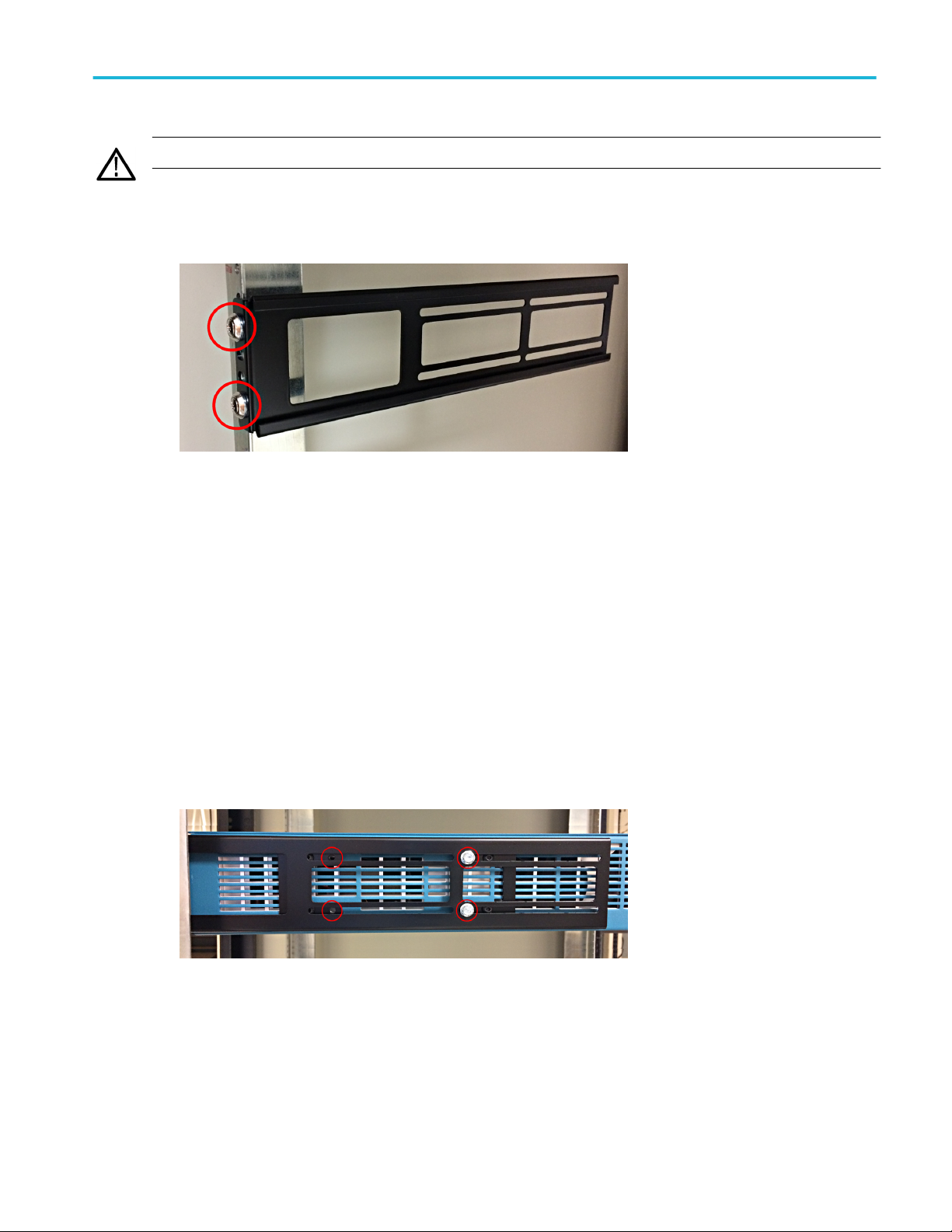
8. Using a 5/16 inch wrench, attach two supplied hexhead bolts to the rack bracket assembly on each side, to lock the
brackets in place and prevent the instrument from unintentional removal when the front rack screws are removed (see the
following image). There are four bolt positions available on each side (see image). Tighten the bracket lock bolts to 0.7 N·m.
9. Attach power cord and cables to rear chassis as needed.
End of rack mount instructions.
LPD64 Installation and Safety Manual 3
Page 16
Installing your instrument
Secure (lock) the instrument
Lock an instrument to a test bench or equipment rack to prevent property loss.
Attach a standard laptop security lock to the rear panel of the instrument, to secure the instrument to a workbench, rack, or other
location.
Powering the instrument
Use this procedure to connect the instrument to line power and power on and off the instrument. Always connect the instrument
to AC power using the power cord that shipped with the instrument.
Prerequisite: Use the AC power cord that shipped with your instrument.
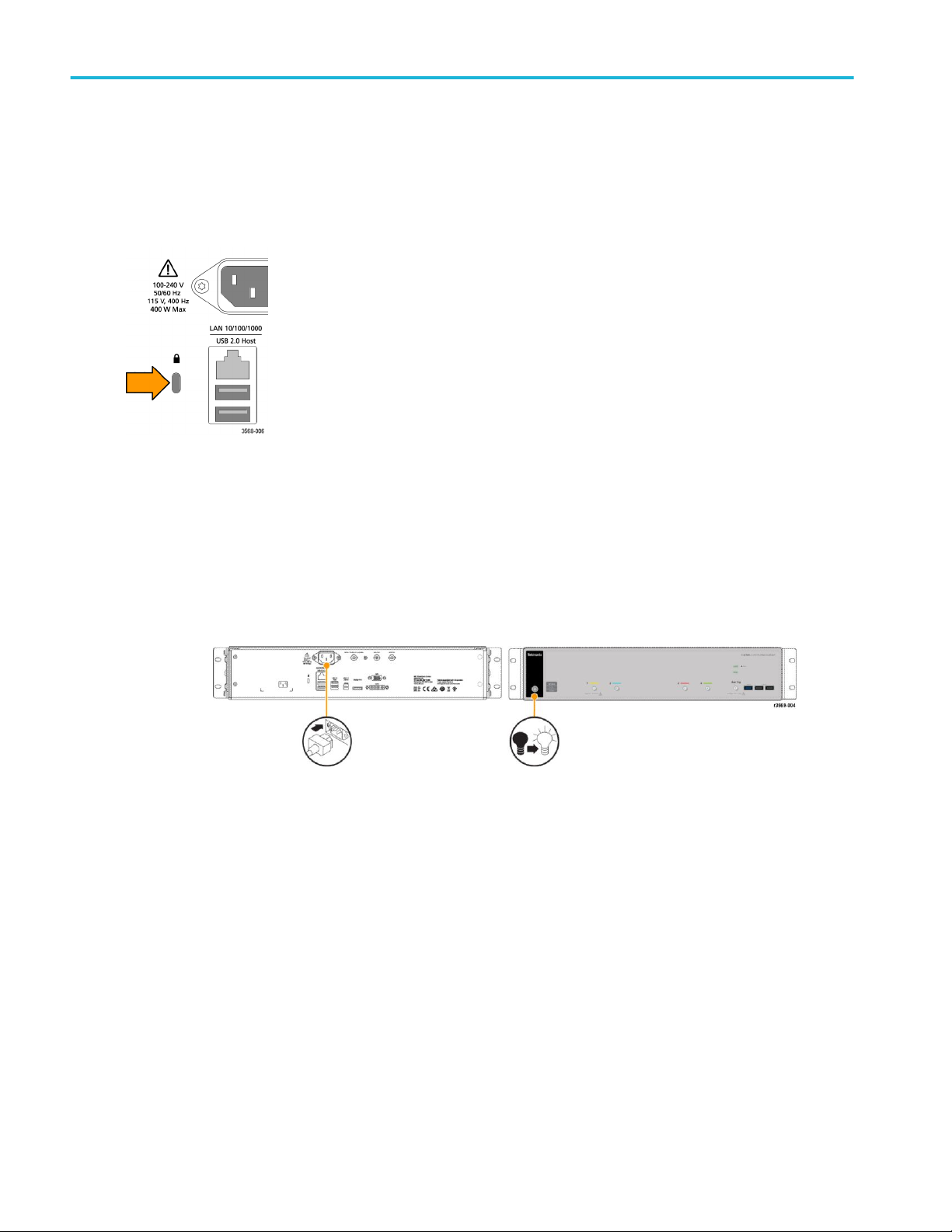
1. Connect the supplied power cord to the instrument power connector on the back of the instrument.
Figure 1: LPD64 power cord connector and power standby switch
2. Connect the power cord to an appropriate AC mains source.
Power is supplied to the power supply and some other boards whenever the AC power cord is connected to a live mains
circuit, putting the instrument in standby mode.
3. Push the front panel power button to power the instrument on and off.
The power button color indicates instrument power states:
Unlit – no AC power applied
Yellow – standby mode
Blue – powered on
4. To completely remove power from the instrument, disconnect the power cord.
4 LPD64 Installation and Safety Manual
Page 17

Installing your instrument
Check that the instrument passes power-on self tests
Power-on self tests verify that all instrument modules are working correctly after power up.
Prerequisite: For the Low Profile instruments, connect a monitor to a video output on the rear panel and connect a mouse to a
USB port.
1. Power on the instrument and wait until the instrument screen appears on the monitor.
2. Select Utility > Self Test from the top-edge Menu bar to open the Self Test configuration menu.
3. Check that the status of all power-on self tests are Passed.
If one or more power-on self tests shows Failed:
a. Power cycle the instrument.
b. Tap Utility > Self Test. If one or more power-on self tests still shows Failed, contact Tektronix Customer Support.
Connecting signals to the instrument
Cables connect the instrument to your device under test (DUT). Use a cable that best matches your signal measurement needs.
Figure 2: Connecting SMA cables to the LPD64
Connecting SMA cables (LPD64)
Connect SMA cables to the instrument. Hand tighten, then torque the cable connectors to 56 N-cm (5 in-lb).
LPD64 Installation and Safety Manual 5
Page 18

Installing your instrument
6 LPD64 Installation and Safety Manual
Page 19

Getting acquainted with your instrument
Front panel controls and connections, LPD64
The front panel is where you power on or off the instrument, connect signals with cables, connect an auxiliary trigger input signal,
and insert USB devices.
The LPD64 front panel
1. Acq status LED:
Shows the instrument trigger/acquisition status:
■
Green - Triggered
■
Yellow - Armed but not yet triggered
■
Red - Acquisition stopped
2. LAN Status LED:
Shows the network connection and activity status:
■
Off - No power to instrument
■
Green - Network connection is good
■
Red - Network connection has fault or is not connected
3. LAN Reset button (to the right of the LAN status LEDs):
Lets you manually reset the LAN settings.
4. USB Host ports (One USB 3.0; two USB 2.0):
Lets you save or recall data (such as instrument firmware updates, waveforms, settings, and screen captures) to a USB
memory device, or connect peripheral devices such as a mouse or keyboard.
5. Aux Trig trigger input connector:
An SMA connector to which you can connect an external trigger input signal. Use the AUX In trigger signal with the Edge
trigger mode.
6. SMA connectors:
LPD64 Installation and Safety Manual
7
Page 20

Getting acquainted with your instrument
SMA connectors support high bandwidth and frequency cables.
7. Power On/Standby button:
Powers the instrument on and off. The power button color indicates instrument power states:
■
No light - No AC power applied
■
Yellow - Standby mode
■
Blue - Powered on
Rear panel connections
The rear panel connections supply power to the instrument and provide connectors for network, USB devices, video, reference
signals, and the AFG output.
5 Series MSO, 6 Series MSO
Figure 3: 5 Series MSO (including MSO58LP) and 6 Series MSO (including LPD64)
1. Power cord connector. Use only the power cord specified for this product and certified for the country of use.
2. Ref In lets you connect a high-precision 10 MHz reference signal to the oscilloscope for more accurate measurements.
3. AUX Out generates a signal transition on a trigger event, outputs a 10 MHz reference signal, or outputs a synchronization
signal from the AFG.
4. AFG Out is the signal output for the optional Arbitrary Function Generator (AFG) feature.
5. Video outputs (Display Port, VGA, and DVI-D) let you connect an external monitor or projector to show the instrument's
graphical user interface.
6. USB 3.0 Device port lets you connect to a PC to remotely control the instrument using USBTMC protocol.
7. USB Host ports let you connect a USB memory device, keyboard, or mouse.
8. LAN connector (RJ-45) connects the instrument to a 10/100/1000 Base-T local area network. The LAN is LXI 1.5 compliant.
9. Security lock connector lets you use a standard PC/laptop lock cable to secure the instrument to a work bench or other
location.
8 LPD64 Installation and Safety Manual
Page 21

Getting acquainted with your instrument
M.2 drive access
The m.2 solid state drive is easily removable when you need to transport the instrument from a secured facility.
The m.2 drive:
■
Contains the system OS
■
Contains all user-related data that was saved to the C: (m.2) drive (waveforms, measurements, settings, and so on)
■
Is easily accessed from the bottom of the instrument with just a Torx screwdriver
NOTE. Licensed functions (installed options) and calibration constants are stored in the instrument, not on the m.2 drive.
NOTE. With the LPD64 6-SEC security option (installed at initial purchase), there is no C: drive on the instrument. User data
such as waveform acquisitions and vertical, horizontal, and trigger settings, are not retained on the m.2 drive after the instrument
is powered off. All acquisition data and setup information must be stored on external memory (USB or network).
To remove an m.2 drive:
CAUTION. Work on the instrument in an anti-static work area and use a wrist strap when removing or installing an m.2 drive.
Failing to do so could damage the m.2 board and the circuit board to which it connects.
1. Disconnect the power cord or unplug the instrument from the power source.
2. Turn the instrument bottom-up.
3. Locate the m.2 drive cover near the corner of the instrument.
4. Use a T-10 Torx screw driver to remove the three screws on the Sold State Drive cover, and remove the cover.
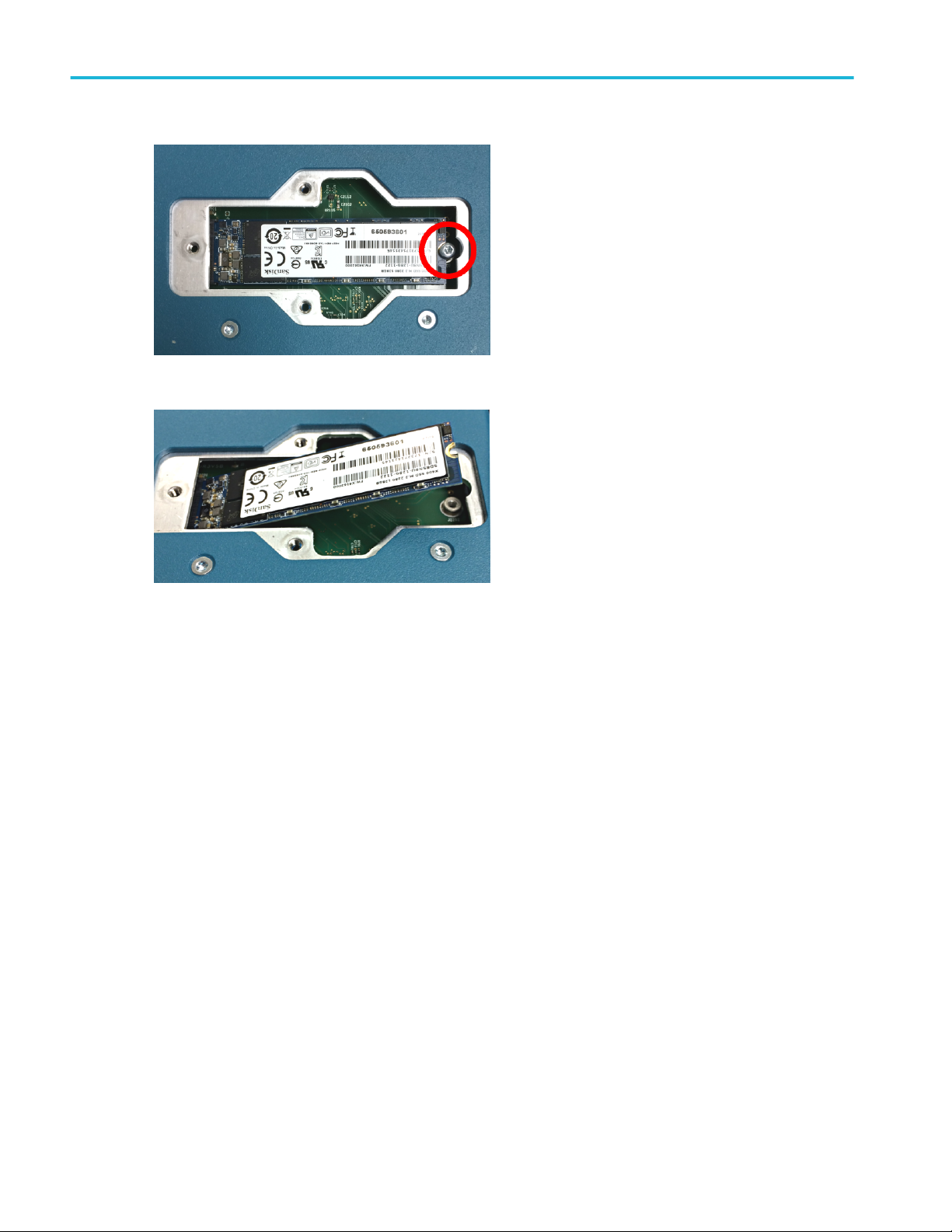
5. Use a T-10 Torx screwdriver to remove the screw from the end of the m.2 drive. The end of the m.2 board lifts upward as
you loosen the screw.
LPD64 Installation and Safety Manual 9
Page 22
Getting acquainted with your instrument
6. Grasp the edges of the raised end and pull to remove the board.
7. Store or destroy the memory card in accordance with your organization’s guidelines.
8. To install an m.2 board, follow these steps in reverse order.
9. Reattach the board cover.
The graphical user interface
Although designed for programmatic control, the LPD64 also has a graphical user interface that incorporates product Help topics.
You can access the graphical interface by connecting a monitor and mouse to the instrument, or by using a browser to access a
network-connected instrument.
Connect a monitor (standard or touchscreen) with a maximum resolution of 1,920 horizontal × 1,080 vertical pixels (High
Definition) to a video out connector on the rear panel.
To access from a browser, type the IP address of the instrument in the browser address field to open the instrument's browser
welcome page. Click the Instrument Control (e*Scope®) link on the left of the screen to open the graphical interface.
Connect a mouse (USB cable) or mouse dongle (for USB wireless mouse) to any USB port.
Refer to the 6 Series MSO Installation and Safety Manual (Tektronix part number 071-3579-xx), available to download from
www.tek.com/product-support, for details on understanding and using the graphical user interface.
You can also get information by opening the instrument Help system. Select Help > Help in the Menu bar and open the Getting
acquainted with your instrument topic.
10 LPD64 Installation and Safety Manual
Page 23
Configure the instrument
To access the user interface on a Low Profile instrument, connect a monitor to a video port on the rear of the instrument, and
connect a mouse to any USB Host port. You do not need to connect a mouse if your remote monitor is touch-capable. You can
also remotely access the user interface of a network-connected instrument by entering the instrument's IP address in a web
browser.
To remotely set controls or run this task on a Low Profile instrument, see the instrument Programmer Manual (Tektronix part
number 077-1305-xx) for the correct command or commands to use.
Set the time zone and clock readout format
Set the time zone to your region so that saved files are marked with the correct date and time information. You can also set the
time format (12 or 24 hour clock).
To access the user interface on a Low Profile instrument, connect a monitor to a video port on the rear of the instrument, and
connect a mouse to any USB Host port. You do not need to connect a mouse if your remote monitor is touch-capable. You can
also remotely access the user interface of a network-connected instrument by entering the instrument's IP address in a web
browser.
To remotely set a control or run this task on a Low Profile instrument, see the instrument Programmer Manual (Tektronix part
number 077-1305-xx) for the correct command or commands to use.
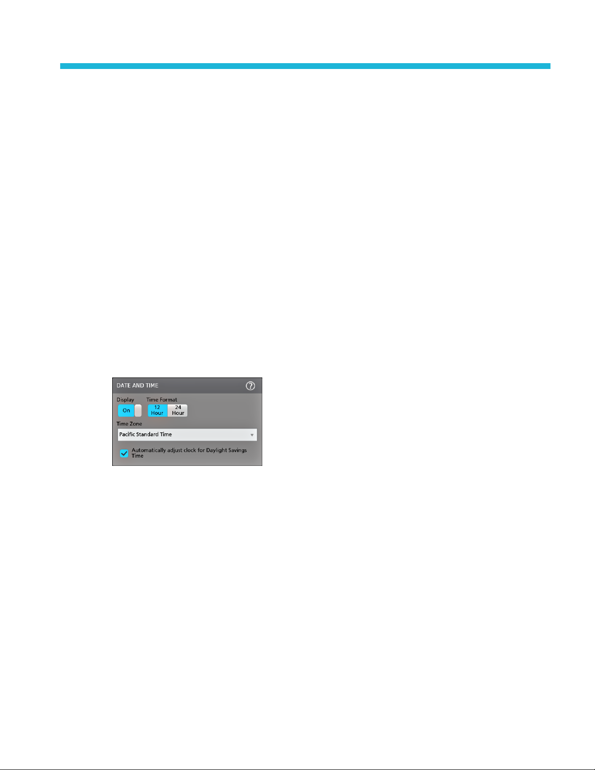
1. Double-tap the Date/Time badge (bottom-right of screen) to open the configuration menu.
2. To turn off showing the date and time on the screen, tap the Display button to Off.
To turn on date/time display again, double-tap in the blank area where the date/time badge was displayed to open the
configuration menu, and set the Display button to On.
3. Select a time format (12 Hour or 24 Hour).
4. Tap the Time Zone field and select the time zone that applies to your location.
5. Tap anywhere outside of the menu to close it.
LPD64 Installation and Safety Manual 11
Page 24

Configure the instrument
Download and install the latest instrument firmware
Installing the latest firmware helps ensure that your instrument has the lastest features and is taking the most accurate
measurements.
To access the user interface on a Low Profile instrument, connect a monitor to a video port on the rear of the instrument, and
connect a mouse to any USB Host port. You do not need to connect a mouse if your remote monitor is touch-capable. You can
also remotely access the user interface of a network-connected instrument by entering the instrument's IP address in a web
browser.
Prerequisite: Save any important on-instrument files (waveforms, screen captures, setups, and so on) to a USB drive or network.
The installation process does not remove user-created files, but it is a good idea to back up important files before an update.
Prerequisite: Determine the current version of firmware installed on the instrument (see Help > About).
Update instrument firmware from a USB drive
1. To download the instrument firmware and install onto a USB drive:
a. Open up a Web browser on a PC and go to www.tek.com/product-support.
b. Enter the instrument model number in the search field and click Go.
c. Scroll down the screen and click the Software tab.
d. If the listed available firmware version (Windows or non-Windows) is newer than what is on your instrument, select and
download that file to your PC.
e. Follow the installation instructions that are on the web site or that came with the downloaded firmware to create the
firmware install file.
f. Copy the firmware install file to a USB flash drive.
2. To install firmware on standard instruments:
a. Power on the instrument and wait for the instrument to fully boot up.
b. Insert the USB flash drive into any instrument USB Host port.
c. The instrument detects the update firmware and opens a dialog box. Follow the on-screen instructions to install the
firmware.
NOTE. Do not power off the instrument or remove the USB flash drive until the instrument finishes installing the firmware.
The instrument displays a message when it is OK to power off. Remove the USB drive before powering on the instrument.
3. To install firmware on instruments with the Windows option:
a. Close the TekScope program before updating the firmware.
b. Insert the USB drive into any instrument USB Host port.
c. Open the Windows desktop File Explorer and navigate to and select the install file.
d. Run the firmware update file from the USB drive, or copy the firmware update file to the desktop and run the file from
there.
e. Follow any on-screen instructions to install the firmware.
12 LPD64 Installation and Safety Manual
Page 25

Configure the instrument
f. When the firmware install is finished, remove the USB drive and restart the instrument.
NOTE. Do not power off the instrument, or remove the USB flash drive if installing from the drive, until the instrument
finishes installing the firmware. The instrument displays a message when it is OK to power off.
4. To confirm that the firmware was updated:
a. Tap Help > About in the Menu bar.
b. Check that the firmware version number listed on the screen is the same version that you downloaded.
Run Signal Path Compensation (SPC)
Run SPC when you first receive an instrument, and at regular intervals, for best measurement accuracy. You should run SPC
whenever the ambient (room) temperature has changed by more than 5 °C (9 °F), or once a week if you use vertical scale
settings of 5 mV per division or less.
To access the user interface on a Low Profile instrument, connect a monitor to a video port on the rear of the instrument, and
connect a mouse to any USB Host port. You do not need to connect a mouse if your remote monitor is touch-capable. You can
also remotely access the user interface of a network-connected instrument by entering the instrument's IP address in a web
browser.
Signal Path Compensation (SPC) corrects for DC level inaccuracies in the internal signal path, caused by temperature variations
and/or long-term signal path drift. Failure to run SPC on a regular basis may result in the instrument not meeting warranted
performance levels at low volts per division settings.
1. Power on and warm up the instrument for at least 20 minutes.
2. Tap Utility > Calibration.
3. Tap Run SPC. The SPC Status readout shows Running while SPC is running. SPC can take several minutes per channel
to run, so wait until the SPC Status message changes to Pass before using the instrument.
CAUTION. You can abort the SPC calibration by tapping Abort SPC. This may leave some channels uncompensated,
resulting in possible inaccurate measurements. If you do abort the SPC, make sure to run the SPC procedure completely
before using the instrument to take measurements.
4. Close the Calibration configuration dialog when SPC has completed.
5. If the SPC fails, write down any error message text. Make sure that all probes and cables are disconnected (except for the
LPD64) and run the SPC again. If the SPC still fails, contact Tektronix Customer Support.
Connect to a network (LAN)
Connecting to a network allows you to remotely access the instrument.
To access the user interface on a Low Profile instrument, connect a monitor to a video port on the rear of the instrument, and
connect a mouse to any USB Host port. You do not need to connect a mouse if your remote monitor is touch-capable. You can
also remotely access the user interface of a network-connected instrument by entering the instrument's IP address in a web
browser.
Work with your network administrator to obtain the required information to connect to your network (IP address, Gateway IP
address, Subnet Mask, DNS IP address, and so on).
1. Connect a CAT5 cable from the instrument LAN connector to your network.
2. Select Utility > I/O on the menu bar to open the I/O configuration menu.
LPD64 Installation and Safety Manual 13
Page 26

Configure the instrument
3. Obtain or enter the network address information:
■
If your network is DHCP-enabled, and the IP address field does not already show and address, tap Auto to obtain the
IP address information from the network. DHCP mode is the default mode.
■
If your network is not DHCP-enabled, or you need a permanent (non-changing) IP address for this instrument, tap
Manual and enter the IP address and other values provided by your IT or system administrator resource.
4. Tap Test Connection to verify that the network connection is working. The LAN Status icon turns green when the
instrument successfully connects to your network. If you have problems connecting to your network, contact your system
administration resource for help.
The front panel LAN status LED colors display the network connection status:
■
Off - No power to the instrument
■
Green - Network connection is good
■
Red - Network connection has a fault or is not connected
Remote access from a Web browser (standard instrument)
You can remotely access your network-connected standard instrument (not running Windows) from a Web browser to display the
instrument user interface on a PC.
This procedure describes how to remotely access the UI controls and screen for standard (non Windows 10) instruments. To
remotely access the UI controls and screen for Windows 10 instruments, see the Remote access to a Windows 10 instrument
topic in the Help.
Prerequisites:
■
The instrument must be connected to, and accessible from, the network to which the PC is connected. See Connect to a
network (LAN) on page 13
■
The IP address of the instrument that you want to access. To determine the instrument's IP address, select Utility > IO in
the instrument menu bar and view the network settings in the LAN panel.
■
You are accessing a standard (instrument that does not have the Windows OS option installed).
1. Open a Web browser on a PC connected to the same network as the instrument.
2. Enter just the instrument IP address on the URL line of the browser and press Enter. For example: 135.62.88.157. The
browser searches for and opens the Web page for the instrument.
14 LPD64 Installation and Safety Manual
Page 27

Configure the instrument
3. Select Instrument Control (e*Scope®). The browser displays the instrument screen.
4. Use a mouse to select and interact with the instrument controls shown in the Web browser. If your remote PC or laptop has
a touch screen monitor, you can use the remote touchscreen monitor to access the instrument controls.
NOTE. When you access the instrument from an e*Scope browser, you cannot directly paste text (such as path, IP address
information, and so on) from the PC to an instrument menu field. You must use an intermediate clipboard function that is
available in the e*Scope application.
Use the following steps to copy text from an e*Scope-connected PC to the instrument:
a.
Open a connection to the instrument using e*Scope.
b.
Select and copy the text on your PC.
c.
In e*Scope, press Ctrl-Alt-Shift to open the Clipboard menu.
d.
Paste the text into the Clipboard field.
e.
Press Ctrl-Alt-Shift to close the browser Clipboard menu.
f.
Use e*Scope to open the instrument menu to which to paste content, and position the cursor in the field where you
want to paste the text.
g.
Press Ctrl-V (on real keyboard or from virtual keyboard) to paste the text from the e*Scope browser clipboard to the
menu field.
h.
Repeat steps 4.b through 4.g to copy and paste other text from the PC to the instrument.
LPD64 Installation and Safety Manual 15
Page 28

Configure the instrument
16 LPD64 Installation and Safety Manual
Page 29

Operating basics
Operating basics
Refer to the 6 Series MSO (MSO64) Installation and Safety Manual (Tektronix part number 071-3579-xx) for details on
understanding and using the graphical user interface to trigger on and acquire waveforms and take measurements.
Refer to the 4/5/6 Series MSO (MSO44, MSO46, MSO54, MSO56, MSO58, MSO58LP, MSO64, LPD64 ) Programmer Manual
(Tektronix part number 077-1305-xx) for the correct command or commands to use to remotely operate the instrument.
Both manuals are available to download from www.tek.com/product-support.
LPD64 Installation and Safety Manual 17
Page 30

Operating basics
18 LPD64 Installation and Safety Manual
Page 31

Maintenance
Maintenance
This section contains information needed to perform periodic maintenance on the instrument.
CAUTION. Do not remove the top cover from the instrument except to replace a damaged cover. There are no user replaceable
parts inside the instrument. Return the instrument to Tektronix if it requires service.
Cleaning
Use a dry, soft cotton cloth to clean the outside of the unit. If any dirt remains, use a cloth or swab dipped in a 75% isopropyl
alcohol solution. Use a swab to clean narrow spaces around controls and connectors. Do not use any liquid cleaning agents or
chemicals that could damage the case, controls, markings or labels, or possibly infiltrate the case.
Performance verification interval and adjustment
The voltage and timing references inside the instrument are very stable over time and do not need routine adjustment.
If periodic calibration is one of your organization's requirements, a general rule is to verify performance every 2000 hours of
operation or once a year if the instrument is used infrequently. Use the procedures in the instrument Specifications and
Performance Verification manual, available online at www.www.tek.com/product-support.
If the instrument fails the performance tests in the Specifications and Performance Verification manual, adjustment may be
required. Adjustment can only be performed by a Tektronix Service Center. See Contacting Tektronix, following the title page in
this manual, for information on contacting Tektronix Service Support.
Replaceable parts list
This section contains replaceable parts information for your instrument. Use the lists in the appropriate section to identify and
order replacement parts for your product.
Standard accessories
Standard accessories for these products are listed near the beginning of this manual.
LPD64 Installation and Safety Manual 19
Page 32

Maintenance
Replaceable parts
The following figure shows the user-replaceable parts for the instrument. There are no user-replaceable parts inside the
instrument.
Figure 4: LPD64 replaceable parts diagram
20 LPD64 Installation and Safety Manual
Page 33

Maintenance
Table 1: Replaceable parts list
Index
number
1 407-6088-xx 2 BRACKET, FRONT, RACK MOUNT, 2U EAR
2 211-1682-xx 14 SCREW, 10-32 X 5/16 BUTTON HEAD, CAP, BLACK
3 407-6089-xx 2 BRACKET, REAR, RACK MOUNT, CHASSIS-SIDE
4 407-6090-xx 2 BRACKET, REAR, RACK MOUNT, RACK-SIDE
5 020-3180-xx 1 BENCH CONVERSION KIT (optional accessory)
Not shown:
Tektronix part number Qty Name & description
A0 1 North America power plug (115 V, 60 Hz)
A1 1 Universal Euro power plug (220 V, 50 Hz)
A2 1 United Kingdom power plug (240 V, 50 Hz)
A3 1 Australia power plug (240 V, 50 Hz)
A5 1 Switzerland power plug (220 V, 50 Hz)
A6 1 Japan power plug (100 V, 50/60 Hz)
A10 1 China power plug (50 Hz)
A11 1 India power plug (50 Hz)
A12 1 Brazil power plug (60 Hz)
LPD64 Installation and Safety Manual 21
Page 34

Maintenance
22 LPD64 Installation and Safety Manual
Page 35

EMC Safety and environmental compliance
Compliance Information
This section lists the EMC (electromagnetic compliance), safety, and environmental standards with which the instrument
complies. This product is intended for use by professionals and trained personnel only; it is not designed for use in households or
by children.
Questions about the following compliance information may be directed to the following address:
Tektronix, Inc.
PO Box 500, MS 19-045
Beaverton, OR 97077, USA
www.tek.com
EMC compliance
EU EMC Directive
Meets intent of Directive 2014/30/EU for Electromagnetic Compatibility. Compliance was demonstrated to the following
specifications as listed in the Official Journal of the European Communities:
EN 61326-1, EN 61326-2-1. EMC requirements for electrical equipment for measurement, control, and laboratory use.
1 2 3
4
■
CISPR 11. Radiated and conducted emissions, Group 1, Class A
■
IEC 61000-4-2. Electrostatic discharge immunity
■
IEC 61000-4-3. RF electromagnetic field immunity
■
IEC 61000-4-4. Electrical fast transient / burst immunity
■
IEC 61000-4-5. Power line surge immunity
■
IEC 61000-4-6. Conducted RF immunity
■
IEC 61000-4-11. Voltage dips and interruptions immunity
EN 61000-3-2. AC power line harmonic emissions
EN 61000-3-3. Voltage changes, fluctuations, and flicker
1
This product is intended for use in nonresidential areas only. Use in residential areas may cause electromagnetic interference.
2
Emissions which exceed the levels required by this standard may occur when this equipment is connected to a test object.
3
Equipment may not meet the immunity requirements of applicable listed standards when test leads and/or test probes are connected due to coupling of electromagnetic
interference onto those leads/probes. To minimize the influence of electromagnetic interference, minimize the loop area between the unshielded portions of signal and
associated return leads, and keep leads as far away as possible from electromagnetic disturbance sources. Twisting unshielded test leads together is an effective way to
reduce loop area. For probes, keep the ground return lead as short as possible and close to the probe body. Some probes have accessory probe tip adapters to
accomplish this most effectively. In all cases, observe all safety instructions for the probes or leads used.
4
For compliance with the EMC standards listed here, high quality shielded interface cables that incorporate low impedance connection between the cable shield and the
connector shell should be used.
LPD64 Installation and Safety Manual 23
Page 36

EMC Safety and environmental compliance
EMC Compliance
Meets the intent of Directive 2014/30/EU for Electromagnetic Compatibility when it is used with the product(s) stated in the
specifications table. Refer to the EMC specification published for the stated products. May not meet the intent of the directive if
used with other products.
Australia / New Zealand Declaration of Conformity – EMC
Complies with the EMC provision of the Radiocommunications Act per the following standard, in accordance with ACMA:
■
EN 61326-1 and EN 61326-2-1. Radiated and conducted emissions, Group 1, Class A.
Safety compliance
This section lists the safety standards with which the product complies and other safety compliance information.
EU low voltage directive
Compliance was demonstrated to the following specification as listed in the Official Journal of the European Union:
Low Voltage Directive 2014/35/EU.
■
EN 61010-1. Safety Requirements for Electrical Equipment for Measurement, Control, and Laboratory Use – Part 1: General
Requirements.
■
EN 61010-2-030. Safety Requirements for Electrical Equipment for Measurement, Control, and Laboratory Use – Part
2-030: Particular requirements for testing and measuring circuits.
U.S. nationally recognized testing laboratory listing
■
UL 61010-1. Safety Requirements for Electrical Equipment for Measurement, Control, and Laboratory Use – Part 1: General
Requirements.
■
UL 61010-2-030. Safety Requirements for Electrical Equipment for Measurement, Control, and Laboratory Use – Part
2-030: Particular requirements for testing and measuring circuits.
Canadian certification
■
CAN/CSA-C22.2 No. 61010-1. Safety Requirements for Electrical Equipment for Measurement, Control, and Laboratory Use
– Part 1: General Requirements.
■
CAN/CSA-C22.2 No. 61010-2-030. Safety Requirements for Electrical Equipment for Measurement, Control, and Laboratory
Use – Part 2-030: Particular requirements for testing and measuring circuits.
Additional compliances
■
IEC 61010-1. Safety Requirements for Electrical Equipment for Measurement, Control, and Laboratory Use – Part 1:
General Requirements.
■
IEC 61010-2-030. Safety Requirements for Electrical Equipment for Measurement, Control, and Laboratory Use – Part
2-030: Particular requirements for testing and measuring circuits.
Equipment type
Test and measuring equipment.
24 LPD64 Installation and Safety Manual
Page 37

EMC Safety and environmental compliance
Safety class
Class I -- grounded product.
Pollution degree description
A measure of the contaminants that could occur in the environment around and within a product. Typically the internal
environment inside a product is considered to be the same as the external. Products should be used only in the environment for
which they are rated.
■
Pollution Degree 1. No pollution or only dry, nonconductive pollution occurs. Products in this category are generally
encapsulated, hermetically sealed, or located in clean rooms.
■
Pollution Degree 2. Normally only dry, nonconductive pollution occurs. Occasionally a temporary conductivity that is caused
by condensation must be expected. This location is a typical office/home environment. Temporary condensation occurs only
when the product is out of service.
■
Pollution Degree 3. Conductive pollution, or dry, nonconductive pollution that becomes conductive due to condensation.
These are sheltered locations where neither temperature nor humidity is controlled. The area is protected from direct
sunshine, rain, or direct wind.
■
Pollution Degree 4. Pollution that generates persistent conductivity through conductive dust, rain, or snow. Typical outdoor
locations.
Pollution degree rating
Pollution Degree 2 (as defined in IEC 61010-1). Note: Rated for indoor, dry location use only.
IP rating
IP20 (as defined in IEC 60529).
Measurement and overvoltage category descriptions
Measurement terminals on this product may be rated for measuring mains voltages from one or more of the following categories
(see specific ratings marked on the product and in the manual).
■
Measurement Category II. For measurements performed on circuits directly connected to the low-voltage installation.
■
Measurement Category III. For measurements performed in the building installation.
■
Measurement Category IV. For measurements performed at the source of low-voltage installation.
NOTE. Only mains power supply circuits have an overvoltage category rating. Only measurement circuits have a measurement
category rating. Other circuits within the product do not have either rating.
Mains overvoltage category rating
Overvoltage Category II (as defined in IEC 61010-1)
Environmental compliance
This section provides information about the environmental impact of the product.
LPD64 Installation and Safety Manual 25
Page 38

EMC Safety and environmental compliance
Restriction of hazardous substances
Complies with RoHS2 Directive 2011/65/EU.
Product end-of-life handling
Observe the following guidelines when recycling an instrument or component:
Equipment recycling. Production of this equipment required the extraction and use of natural resources. The equipment may
contain substances that could be harmful to the environment or human health if improperly handled at the product’s end of life.
To avoid release of such substances into the environment and to reduce the use of natural resources, we encourage you to
recycle this product in an appropriate system that will ensure that most of the materials are reused or recycled appropriately.
This symbol indicates that this product complies with the applicable European Union requirements according to
Directives 2012/19/EU and 2006/66/EC on waste electrical and electronic equipment (WEEE) and batteries. For
information about recycling options, check the Tektronix Web site (www.tek.com/productrecycling).
Battery recycling
This product contains a small installed lithium metal button cell. Please properly dispose of or recycle the cell at its end of life
according to local government regulations.
Perchlorate materials. This product contains one or more type CR lithium batteries. According to the state of California, CR
lithium batteries are classified as perchlorate materials and require special handling. See
www.dtsc.ca.gov/hazardouswaste/perchlorate for additional information.
Transporting batteries
The small lithium primary button cell contained in this equipment does not exceed 1 gram of lithium metal content per cell, and
the cell type has been shown by the manufacturer to comply with the applicable requirements of the UN Manual of Tests and
Criteria Part III, Sub-section 38.3. Consult your carrier to determine which lithium battery transportation requirements are
applicable to your configuration, including to its re-packaging and re-labeling, prior to reshipment of the product by any mode of
transport
26 LPD64 Installation and Safety Manual
Page 39

Index
A
ACQ acquisition status LED, 7
AFG Out (rear panel), 8
AUX Out (rear panel), 8
Aux Trig trigger input, 7
C
cable lock, 8
clock format (12/24 hr), how to set, 11
connect lock cable, 4
connect to a network, 13
connecting probes, 5
L
LAN port (rear panel), 8
LAN status LEDs, 7
LAN, connect to, 13
lock to bench or rack, 4
M
Maintenance
replaceable parts, 19
N
E
e*Scope, 14
Environment requirements, 1, 2
Ethernet port (rear panel), 8
Ethernet, connect to, 13
F
firmware, how to update, 12
FlexChannel inputs, 7
front panel controls, 7
H
how to
check power-on self tests results, 5
connect probes, 5
connect to network, 13
download, install firmware, 12
remote access the instrument (from Web), 14
run signal path compensation (SPC), 13
set clock format (12/24 hr), 11
set time zone, 11
update firmware, 12
I
input signal level requirements, 2
network, connect to, 13
O
operating
altitude range, 1, 2
humidity range, 1, 2
temperature range, 1, 2
operating power requirements, 1, 2
P
power cord connector (rear panel), 8
power cords, 19
power requirements, 1, 2
power standby mode, 4
power-on test results, 5
powering on or off, 4
probes, connecting, 5
R
rear panel
AFG Out, 8
AUX Out, 8
cable lock, 8
Ethernet port (RJ-45), 8
LAN port (RJ-45), 8
LPD64 Installation and Safety Manual 27
Page 40

Index
power cord, 8
security cable lock, 8
USB Device port, 8
USB Host ports, 8
video output, 8
rear panel connections, 8
Ref In, 8
Ref In (rear panel), 8
remote access (e*Scope), 14
remote access (Web-based), 14
remove AC power from instrument, 4
Replaceable parts, 19
requirements
altitude, 1, 2
environment, 1, 2
humidity, 1, 2
power, 1, 2
signal inputs, 2
temperature, 1, 2
run signal path compensation, 13
set
clock format (12/24 hr), 11
time zone, 11
signal input levels, 2
SPC (signal path compensation), 13
standard accessories, 1
T
time zone, how to set, 11
turn instrument on or off, 4
U
USB Device port (rear panel), 8
USB Host ports (rear panel), 8
V
video output (rear panel), 8
S
security cable lock, 8
28 LPD64 Installation and Safety Manual
Page 41

LPD64
Numériseur profil bas Série 6
Manuel d’installation et de sécurité
*P071365900*
071365900
Page 42

Page 43

LPD64
Numériseur profil bas Série 6
Manuel d’installation et de sécurité
Prise en charge du firmware produit V1.20.x et ultérieures
www.tek.com
071365900
Page 44

Copyright © Tektronix. Tous droits réservés. Les produits logiciels sous licence sont la propriété de Tektronix, de ses filiales ou de ses
fournisseurs et sont protégés par les lois nationales sur le copyright, ainsi que par des traités internationaux. Les produits Tektronix sont
protégés par des brevets américains et étrangers déjà déposés ou en cours d'obtention. Les informations contenues dans le présent
document remplacent celles publiées précédemment. Les spécifications et les prix peuvent être soumis à modification.
TEKTRONIX et TEK sont des marques déposées de Tektronix, Inc.
Prendre contact avec Tektronix
Tektronix, Inc.
14150 SW Karl Braun Drive
P.O. Box 500
Beaverton, OR 97077
États-Unis
Pour obtenir des informations sur le produit, la vente, le service après-vente et l’assistance technique :
•
En Amérique du Nord, appelez le 1-800-833-9200.
•
Pour les autres pays, visitez le site www.tek.com pour connaître les coordonnées locales.
Page 45

Sommaire
Informations importantes relatives à la sécurité .................................................................................................. iii
Consignes générales de sécurité .................................................................................................................. iii
Consignes générales de maintenance .......................................................................................................... vi
Termes utilisés dans le manuel ..................................................................................................................... vi
Mentions figurant sur le produit ..................................................................................................................... vi
Symboles figurant sur le produit ................................................................................................................... vii
Préface ................................................................................................................................................................ ix
Principales fonctionnalités ............................................................................................................................. ix
Documentation connexe
Chapitre 1: Installation de l’instrument
Vérification des accessoires reçus ................................................................................................................. 1
Conditions de fonctionnement requises ......................................................................................................... 1
Conditions requises pour le signal d’entrée ................................................................................................... 2
Installation de l’instrument dans une baie ...................................................................................................... 2
Verrouillage de l’instrument ............................................................................................................................ 4
Mise sous tension de l’instrument .................................................................................................................. 4
Vérifiez que l’instrument réussit les auto-tests à la mise sous tension. ......................................................... 5
Connexion de signaux sur l’instrument .......................................................................................................... 5
................................................................................................................................. x
Chapitre 2: Présentation de l’instrument
Commandes et connecteurs de la face avant, LPD64 ................................................................................... 7
Connecteurs du panneau arrière ................................................................................................................... 8
Accès au disque m.2 ...................................................................................................................................... 9
Interface utilisateur graphique ...................................................................................................................... 10
Chapitre 3: Configuration de l’instrument
Réglage du fuseau horaire et du format d’horloge ....................................................................................... 11
Téléchargement et installation de la version la plus récente du firmware de l’instrument ........................... 12
Compensation du chemin du signal (SPC) .................................................................................................. 13
Connexion à un réseau local (LAN) ............................................................................................................. 14
Accès à distance depuis un navigateur Web (instrument standard) ............................................................ 14
Chapitre 4: Principes de fonctionnement
Principes de fonctionnement ....................................................................................................................... 17
Manuel d’installation et de sécurité du numériseur LPD64 i
Page 46

Sommaire
Chapitre 5: Maintenance
Maintenance
Nettoyage ..................................................................................................................................................... 19
Réglage et fréquence de vérification des performances .............................................................................. 19
Liste des pièces de rechange ...................................................................................................................... 20
................................................................................................................................................. 19
Chapitre 6: Conformité environnementale et sécurité CEM
Informations relatives à la conformité .......................................................................................................... 23
Conformité CEM ..................................................................................................................................... 23
Conformité en matière de sécurité ......................................................................................................... 24
Conformité environnementale ................................................................................................................ 26
ii Manuel d’installation et de sécurité du numériseur LPD64
Page 47

Informations importantes relatives à la sécurité
Ce manuel contient des informations et des avertissements que l'utilisateur doit impérativement respecter pour sa sécurité et
maintenir le produit en bon état.
Pour entretenir ce produit en toute sécurité, consultez les Consignes générales de maintenance qui suivent les Consignes
générales de sécurité.
Consignes générales de sécurité
Utilisez le produit uniquement dans les conditions spécifiées. Veuillez lire attentivement les précautions et consignes de sécurité
suivantes afin d'éviter toute blessure et toute détérioration matérielle de l'appareil et des produits qui lui sont connectés. Lisez
attentivement toutes les instructions. Conservez-les pour vous y reporter ultérieurement.
Ce produit doit être utilisé conformément aux codes locaux et nationaux.
Pour utiliser correctement et en toute sécurité ce produit, il est essentiel de respecter les procédures générales de sécurité en
vigueur en plus des consignes indiquées dans ce manuel.
Seul du personnel qualifié peut utiliser ce produit.
Seul du personnel qualifié connaissant les risques encourus peut enlever le capot pour effectuer des réparations, des opérations
de maintenance ou des réglages.
Avant d'utiliser l'appareil, contrôlez-le toujours avec une alimentation connue pour vérifier qu'il fonctionne correctement.
Ce produit n'est pas conçu pour détecter des tensions dangereuses.
Utilisez un équipement de protection personnel afin de vous protéger contre les risques d'électrocution et d'arc électrique
associés à l'exposition à des conducteurs sous tension.
En utilisant ce produit, vous pouvez avoir besoin d’accéder à d’autres composants d'un système plus important. Lisez les
consignes de sécurité des autres composants du système pour connaître les avertissements et les précautions d'utilisation du
système.
Si cet appareil est intégré dans un système, l'assembleur est responsable de la sécurité de ce système.
Pour éviter un incendie ou des blessures
Utilisez un cordon d'alimentation adapté. Utilisez uniquement le cordon d'alimentation prévu pour cet appareil et conforme
aux normes du pays d'utilisation. N'utilisez pas le cordon d'alimentation d'un autre appareil.
Raccordez l'appareil à la terre. Ce produit est raccordé à la terre par le fil de masse du cordon d'alimentation. Pour éviter tout
risque d'électrocution, ce fil de masse doit être connecté à une prise de terre. Avant de procéder aux branchements des bornes
d'entrée et de sortie du produit, veillez à ce que celui-ci soit correctement mis à la terre. Ne débranchez pas le raccordement à la
terre.
Déconnexion de l'alimentation. Le cordon d'alimentation permet de déconnecter le produit de l'alimentation électrique.
Consultez les instructions pour connaître son emplacement. Ne placez pas l'appareil d’une façon qui rend l'accès au cordon
d'alimentation difficile ; il doit rester accessible à l'utilisateur à tout moment afin de pouvoir le débrancher rapidement si besoin.
Branchez et débranchez correctement l'appareil.. Ne connectez ou ne déconnectez pas les sondes ou les conducteurs de
test lorsqu'ils sont connectés à une source de tension.Utilisez uniquement les sondes de tension isolées, les fils de test et les
adaptateurs fournis avec le produit ou recommandés par Tektronix et adaptés au produit.
Manuel d’installation et de sécurité du numériseur LPD64 iii
Page 48

Informations importantes relatives à la sécurité
Respectez toutes les caractéristiques nominales des bornes.. Pour éviter tout risque d'incendie ou d'électrocution, respectez
toutes les caractéristiques nominales et les marquages du produit. Avant de brancher le produit, consultez le manuel fourni pour
obtenir les caractéristiques nominales. Respectez la catégorie de mesure (CAT) ou la tension et le courant maximales autorisées
pour le composant affichant les caractéristiques les plus faibles d'un produit, d'une sonde ou d'un accessoire. Soyez prudent
lorsque vous utilisez des fils de test 1:1 : en effet, la tension à la pointe de la sonde est transmise directement au produit.
N'appliquez à une borne (y compris la borne commune) aucun potentiel supérieur à la caractéristique maximale de cette borne.
Ne laissez pas la borne commune flottante à une tension supérieure à la tension nominale de cette borne.
Les bornes de mesure de ce produit ne sont pas conçues pour être branchées sur l'alimentation secteur ou sur les circuits de
catégorie II, III et IV.
Ne mettez pas l'appareil en service sans ses capots.. Ne mettez pas l'appareil en service si ses capots sont retirés ou si le
boîtier est ouvert. Vous pouvez être exposé à une tension dangereuse.
Évitez tout circuit exposé.. Ne touchez à aucun branchement ou composant exposé lorsque l’appareil est sous tension.
N'utilisez pas l'appareil si vous suspectez une panne.. En cas de doute sur le bon état de cet appareil, faites-le contrôler par
un technicien qualifié.
Mettez l'appareil hors service s'il est endommagé. N'utilisez pas le produit s'il est endommagé ou s'il ne fonctionne pas
correctement. En cas de doute à propos de la sécurité du produit, éteignez-le et débranchez le cordon d'alimentation. Indiquez
clairement qu'il ne doit pas être utilisé.
Avant toute utilisation, vérifiez que les sondes de tension, les cordons de test et les accessoires ne sont pas mécaniquement
endommagés. Remplacez-les le cas échéant. N'utilisez pas de sondes ou de cordons de test endommagés, si du métal nu est
exposé ou s'il présente des signes d'usure.
Examinez l'extérieur du produit avant de l'utiliser. Recherchez des fissures ou des pièces manquantes.
Utilisez uniquement les pièces de rechange spécifiées.
N'utilisez pas l'appareil dans un environnement humide.. De la condensation peut se former si un appareil est déplacé d'un
environnement froid vers un environnement chaud.
N'utilisez pas l'appareil dans un environnement explosif..
Maintenez les surfaces de l'appareil propres et sèches.. Retirez les signaux d'entrée avant de nettoyer le produit.
Assurez une ventilation adéquate.. reportez-vous aux instructions d'installation du manuel pour installer le produit en
garantissant la ventilation correcte.
Pour la ventilation, l'appareil comporte des ouïes et des ouvertures qui ne doivent jamais être bouchées ou obstruées.
N'enfoncez pas d'objets dans les ouvertures.
Aménagez un environnement de travail sûr.. Placez toujours le produit à un endroit qui permet de voir facilement l'écran et les
voyants.
Évitez toute utilisation prolongée ou inappropriée du clavier, des pointeurs et des boutons. L'utilisation incorrecte ou prolongée
du clavier ou d'un pointeur peut provoquer des blessures graves.
Vérifiez que votre site de travail respecte les normes en vigueur en matière d’ergonomie. Consultez un professionnel du domaine
de la sécurité et de l'ergonomie du poste de travail pour éviter les troubles provoqués par le stress.
Soyez prudent lorsque vous levez ou portez le produit. Ce produit est fourni avec une ou des poignées permettant de le lever et
le porter.
iv Manuel d’installation et de sécurité du numériseur LPD64
Page 49

Informations importantes relatives à la sécurité
AVERTISSEMENT. Ce produit est lourd. Pour réduire les risques de blessure ou de détérioration de l'appareil, faites-vous aider
lorsque vous levez ou portez le produit.
Utilisez uniquement le rack Tektronix prévu pour ce produit.
Sondes et cordons de test
Avant de connecter des sondes ou des cordons de test, branchez le cordon d'alimentation sur une prise correctement reliée à la
terre.
Laissez vos doigts derrière la barrière de protection, la protection pour les doigts ou l’indicateur tactile des sondes.
Retirez les sondes, fils de test et accessoires non utilisés.
Pour la mesure, utilisez uniquement des sondes, des fils de test et des adaptateurs adaptés à la catégorie de mesure (CAT), à la
tension, à la température, à l'altitude et à l'intensité prévues.
Attention aux hautes tensions. Soyez sûr de bien comprendre les valeurs nominales de la sonde que vous utilisez et que vous
ne dépassez pas ces valeurs.Soyez sûr de bien comprendre les valeurs nominales de la sonde que vous utilisez et de ne pas
dépasser pas ces valeurs. Deux valeurs nominales doivent être connues et comprises :
•
Tension de mesure maximale entre l'extrémité de la sonde et le câble de référence de la sonde
•
Tension flottante maximale entre le câble de référence de la sonde et la prise de terre.
Ces deux tensions dépendent de la sonde et de votre application. Pour plus d'informations, consultez la section Spécifications de
ce manuel.
AVERTISSEMENT. Pour éviter tout risque d'électrocution, ne dépassez pas les valeurs maximales de mesure ou de tension
flottante du connecteur d'entrée BNC de l'oscilloscope, de la pointe de la sonde ou du câble de référence de la sonde.
Branchez et débranchez correctement l'appareil.. Branchez la sortie de sonde à l'instrument de mesure avant de brancher la
sonde sur le circuit à tester. Branchez le câble de référence de la sonde sur le circuit à tester avant de brancher l'entrée de la
sonde. Débranchez l'entrée et le câble de référence de la sonde du circuit testé avant de débrancher la sonde de l'instrument de
mesure.
Branchez le fil de référence de la sonde sur la terre uniquement.
Inspectez la sonde et les accessoires.. Avant chaque utilisation, vérifiez si la sonde et les accessoires ne sont pas
endommagés (coupures, déchirures, défauts dans le corps de la sonde, accessoires, gaine de câble). Ne les utilisez pas s'ils
sont endommagés.
Utilisation d'un oscilloscope référencé à la terre. Ne prenez pas de mesures flottantes sur le câble de référence de cette
sonde lorsque vous l'utilisez avec des oscilloscopes référencés à la terre. Ce câble de référence doit être relié à une prise de
terre (0 V).
Utilisation de mesure flottante. N’effectuez aucune mesure flottante sur le câble de référence de cette sonde au-delà de la
tension nominale de flottement.
Manuel d’installation et de sécurité du numériseur LPD64 v
Page 50

Informations importantes relatives à la sécurité
Avertissements et informations relatifs à l’évaluation du risque
Consignes générales de maintenance
Le paragraphe Consignes générales de maintenance contient les informations nécessaires à l'entretien de ce produit. Seul un
personnel qualifié doit effectuer les opérations d'entretien. Lisez attentivement ce paragraphe
générales de sécurité avant toute intervention de maintenance.
Pour éviter tout risque d'électrocution. Ne touchez pas aux connexions exposées.
Ne travaillez pas seul. N'intervenez pas et n'effectuez aucun réglage à l'intérieur de l'appareil sauf en présence d'une autre
personne pouvant apporter les premiers soins et connaissant les techniques de réanimation.
Débranchez l'alimentation. Pour éviter tout risque d'électrocution, éteignez l'appareil et débranchez le cordon d'alimentation du
secteur avant d'enlever des capots ou des panneaux, ou d'ouvrir le boîtier pour une intervention.
Faites extrêmement attention lorsque vous intervenez si l'appareil est sous tension. Des tensions ou des courants
dangereux peuvent être présents dans cet appareil. Débranchez l'alimentation, enlevez la batterie et débranchez les fils de test
(le cas échéant) avant de déposer des panneaux de protection, de souder ou de remplacer des composants.
Vérifiez la sécurité de l'appareil après une réparation. Contrôlez toujours la conductivité à la terre et la rigidité diélectrique du
secteur après une réparation.
et le paragraphe Consignes
Termes utilisés dans le manuel
Ces termes pourraient se trouver dans ce manuel :
AVERTISSEMENT. Les avertissements identifient des situations ou des opérations pouvant entraîner des blessures graves ou
mortelles.
ATTENTION. Les mises en garde identifient des situations ou des opérations susceptibles d'endommager le matériel ou d'autres
équipements.
Mentions figurant sur le produit
Ces termes peuvent apparaître sur le produit :
•
« DANGER » indique un risque de blessure immédiate à la lecture de l'étiquette.
•
« AVERTISSEMENT » indique un risque de blessure non immédiate à la lecture de l'étiquette.
•
« PRÉCAUTION » indique un risque de dommage matériel, y compris du produit.
vi Manuel d’installation et de sécurité du numériseur LPD64
Page 51

Informations importantes relatives à la sécurité
Symboles figurant sur le produit
Lorsque ce symbole est apposé sur le produit, consultez le manuel pour rechercher la nature des dangers potentiels
et les mesures à prendre pour les éviter. (Ce symbole peut également être utilisé pour indiquer à l'utilisateur les
caractéristiques nominales figurant dans le manuel.)
Les symboles suivants peuvent être présents sur le produit :
Manuel d’installation et de sécurité du numériseur LPD64 vii
Page 52

Informations importantes relatives à la sécurité
viii Manuel d’installation et de sécurité du numériseur LPD64
Page 53

Préface
Le présent manuel contient des informations sur la conformité et la sécurité du produit, des instructions pour la connexion et la
mise sous tension, ainsi qu’une présentation des principales commandes et fonctions de l’instrument. Reportez-vous au fichier
d’aide de l’instrument pour obtenir des informations plus détaillées.
Principales fonctionnalités
Numériseur à profil bas LPD64 Série 6.
•
Les instruments à profil bas sans écran sont livrés prêts à installer dans un emplacement de baie 2U.
•
Quatre voies avec entrées SMA 50
•
Bandes passantes de 1/2,5/4/6/8 GHz sur toutes les voies
•
Fréquence d’échantillonnage maximale de 25 G éch./s sur toutes les voies
•
Longueur d’enregistrement de 125 M de points sur toutes les voies (longueur d’enregistrement de 250 M disponible en
option)
•
Résolution analogique/numérique 12 bits
•
Meilleur niveau de bruit de sa catégorie
•
Nombre de bits effectifs (8,2 bits à 1 GHz) le plus élevé de sa catégorie
•
Vitesse de capture des signaux maximale 500 000 signaux/seconde
•
Aucune limite n’est définie pour le nombre de signaux calculés, de référence et de bus que vous pouvez créer ; ce nombre
dépend de la mémoire système disponible.
•
La vue Spectre permet une analyse simple et intuitive du domaine de fréquences, indépendante des commandes de
domaine temporel, afin d’afficher une représentation du spectre pour chacune des voies.
•
DDC 2 GHz en temps réel pour la bande passante RF
•
Le mode d’acquisition à mémoire segmentée FastFrame™ utilise plusieurs événements de déclenchement pour capturer
des événements intéressants largement espacés, à des fréquences d’échantillonnage élevées, tout en conservant la
mémoire d’acquisition.
•
Les options intégrées incluent un générateur de fonctions arbitraires (AFG) 50 MHz, un voltmètre numérique (DVM) et un
compteur de fréquence de déclenchement.
Ω
•
Les options avancées d’analyse et de déclenchement sur bus série vous permettent d’effectuer le décodage et le
déclenchement sur la base des bus sectoriels standard. Reportez-vous à la rubrique d’aide Options de bus série et de
déclenchement pour plus d’informations.
•
Les options de puissance, DPM et de gigue offrent des fonctionnalités de mesure et d’analyse complémentaires. Reportezvous aux rubriques d’aide Analyse avancée de la puissance, Analyse DPM et Analyse de gigue pour plus d’informations.
Manuel d’installation et de sécurité du numériseur LPD64 ix
Page 54

Préface
Documentation connexe
Consultez la documentation connexe pour obtenir plus d’informations sur les fonctions de l’instrument, savoir comment
programmer ou utiliser à distance l’instrument, en comprendre les principes de fonctionnement, remplacer les modules
potentiellement défectueux et effectuer d’autres tâches.
Documents LPD64
En savoir plus sur Consulter ce document
Utilisation des fonctions de
l’instrument
Contrôle à distance de
l’instrument
Spécifications de l’instrument
et procédures permettant de
vérifier que l’instrument est
conforme aux spécifications
Conversion de l’instrument
pour une utilisation sur table
de travail
Manuel d’installation et de sécurité du numériseur profil bas LPD64 Série 6 (ce document,
référence Tektronix 071-3569-xx) ; accessoire standard avec l’instrument. Document unique
disponible en anglais, français et allemand.
Aide MSO Série 4/5/6 (référence Tektronix 077-1303-xx ; version imprimable de l’aide de
l’instrument ; disponible sur www.tek.com/downloads)
Manuel de programmation MSO Série 4/5/6 (référence Tektronix 077-1305-xx ; disponible sur
www.tek.com/downloads)
Référence technique de spécifications et de vérification des performances du numériseur profil
bas LPD64 Série 6 (référence Tektronix 077-1568-xx ; disponible sur www.tek.com/downloads)
Instructions du kit de conversion pour table de travail MSO58LP/LPD64 (référence Tektronix
075-1102-xx ; disponible sur www.tek.com/downloads)
x Manuel d’installation et de sécurité du numériseur LPD64
Page 55

Installation de l’instrument
Vérification des accessoires reçus
Assurez-vous d’avoir reçu tous les articles que vous avez commandés. S’il manque un ou plusieurs articles, prenez contact avec
l’assistance clientèle Tektronix. En Amérique du Nord, appelez le 1-800-833-9200. Pour les autres pays, visitez le site
www.tek.com pour connaître les coordonnées locales.
Vérifiez la liste de colisage fournie avec l’instrument afin de vérifier que vous avez bien reçu tous les accessoires standard et les
articles commandés. Si vous avez acheté des options installées en usine, par exemple une option de déclenchement et de bus
série, appuyez sur Help (Aide) > About (À propos de) pour confirmer que la ou les options figurent bien dans le tableau
Installed Options (Options installées).
Accessoires standard LPD64
Composant Quantité Référence Tektronix
Manuel d’installation et de sécurité du numériseur LPD64 profil bas Série 6 1 071-3569-xx
Cordon d’alimentation 1 En fonction de la région
Certificat d’étalonnage 1 S/O
Liste des licences installées en usine 1 S/O
Conditions de fonctionnement requises
Pour obtenir les mesures les plus précises possibles et utiliser l’instrument en toute sécurité, utilisez celui-ci conformément aux
conditions d’exploitation indiquées en termes de température, de puissance, d’altitude et de plages de tension d’entrée du signal.
Conditions environnementales requises
Caractéristiques Description
Température de fonctionnement 0 °C à +50 °C
Pour assurer un refroidissement adéquat, dégagez les côtés et de l’appareil en
laissant un espace libre de 51 mm.
Humidité de fonctionnement 5 à 90 % d’humidité relative (% HR), température jusqu’à +40 °C, sans
condensation.
5 à 50 % d’humidité relative, température entre +40 et +50 °C, sans condensation.
Altitude de fonctionnement Jusqu’à 3 000 mètres
Manuel d’installation et de sécurité du numériseur LPD64 1
Page 56

Installation de l’instrument
Puissance requise
Caractéristiques Description
Tension de la source d’alimentation 100 V - 240 V
Fréquence de la source d’alimentation 50/60 Hz, 100-240 V
400 Hz, 115 V
Consommation électrique Tous les modèles : 360 W maximum
Valeur efficace CA
, ±10 %, monophasée
Conditions requises pour le signal d’entrée
Conservez les signaux d’entrée dans les limites autorisées, pour garantir les mesures les plus précises possible et éviter
d’endommager les sondes analogiques et numériques ou l’instrument.
Assurez-vous que les signaux d’entrée connectés aux instruments LPD64 sont conformes aux conditions requises suivantes.
Entrée Description
Voies d’entrée analogiques, réglage 50 Ω, tension
d’entrée maximum au connecteur SMA
Tension d’entrée maximum Ref In
(panneau arrière)
Tension de déclenchement Aux In, réglage 50 Ω,
tension d’entrée maximum au connecteur SMA
au BNC
5 V
eff
Surtension transitoire = 0 V. Les bornes de mesure de ce produit ne sont
pas conçues pour être branchées sur l’alimentation secteur ou sur les
circuits de catégorie II, III et IV.
7 V
PP
±5 V
eff
Installation de l’instrument dans une baie
Observez les instructions suivantes pour installer l’instrument à profil bas sur une baie de montage standard de 19" de large par
24" à 32" de profondeur.
L’instrument est fourni avec un crochet de montage sur baie intégré au châssis. Servez-vous des boulons et des rondelles
fournis dans un sachet avec l’instrument pour fixer les crochets de montage arrière à la baie.
Si vous souhaitez utiliser un instrument à profil bas sur un plan de travail, achetez le Kit de conversion pour table de travail
MSO58LP/LPD64 (référence Tektronix 020-3180-xx). Ce kit contient des pieds pour le châssis et une poignée, afin d’empiler les
instruments sur la table de travail.
Observez les étapes suivantes pour installer l’instrument dans une baie de montage :
2 Manuel d’installation et de sécurité du numériseur LPD64
Page 57

Installation de l’instrument
AVERTISSEMENT. Pour éviter toute blessure, prévoyez deux personnes pour installer l’instrument.
1. Utilisez deux boulons et rondelles fournis avec l’instrument pour fixer l’un des crochets de celui-ci aux supports situés sur
l’arrière de la baie. Serrez à la main.
2. En portant l’instrument à deux personnes, insérez celui-ci dans la baie, par l’avant, de manière à ce que le crochet arrière
du châssis se glisse dans le support arrière de la baie.
3. Continuez à pousser par l’avant jusqu’à ce que l’instrument soit entièrement inséré et ne dépasse plus à l’avant de la baie.
4. Utilisez quatre boulons et rondelles fournis avec l’instrument pour fixer la partie avant de celui-ci à la baie. Serrez à la main
pour maintenir l’instrument en place.
5. Depuis l’arrière de la baie, insérez le second support arrière de la baie dans le crochet du châssis, jusqu’à ce qu’il ne
dépasse plus.
6. Utilisez deux boulons et rondelles fournis avec l’instrument pour fixer le second crochet aux supports situés sur l’arrière de
la baie. Serrez à la main.
7. Serrez ensuite l’ensemble des boulons à un couple de 1,1 N·m.
8. À l’aide d’une clé de 5/16 pouces, fixez les deux boulons à tête hexagonale fournis de chaque côté du support de baie, afin
de maintenir les crochets en place et d’éviter que l’instrument ne soit démonté involontairement lors du retrait des vis de
fixation avant (cf. image suivante). Quatre emplacements de fixation sont disponibles de chaque côté pour les boulons (cf.
image). Serrez les boulons de fixation des crochets à un couple de 0,7 N·m.
9. Fixez le cordon d’alimentation et les câbles au châssis arrière; si nécessaire.
Instructions de montage en bout de baie.
Manuel d’installation et de sécurité du numériseur LPD64 3
Page 58

Installation de l’instrument
Verrouillage de l’instrument
Fixez l’instrument sur un banc d’essai ou une baie de montage à l’aide d’un câble de sécurité, pour éviter les vols.
Fixez un câble de sécurité standard pour ordinateur portable sur le panneau arrière de l’instrument, afin de fixer l’instrument à un
banc d’essai, à une baie de montage ou à tout autre élément fixe.
Mise sous tension de l’instrument
Appliquez cette procédure pour brancher l’instrument sur l’alimentation secteur et le mettre sous tension/l’arrêter. Branchez
toujours l’instrument sur une alimentation CA à l’aide du cordon d’alimentation fourni.
Prérequis : utilisez le cordon d’alimentation CA fourni avec votre instrument.
1. Branchez le cordon d’alimentation fourni sur le connecteur d’alimentation de l’instrument, situé sur le panneau arrière.
Illustration 1: Connecteur du cordon d’alimentation et commutateur du mode veille LPD64
2. Branchez le cordon d’alimentation sur une source d’alimentation secteur CA adaptée.
Le courant est transmis à l’alimentation de l’instrument et à diverses cartes électroniques lorsque vous branchez le cordon
d’alimentation CA sur un circuit secteur sous tension, ce qui met l’instrument en mode veille.
3. Appuyez sur le bouton Marche/Arrêt situé sur la face avant pour mettre l’instrument sous/hors tension.
La couleur du bouton Marche/Arrêt indique l’état de l’instrument.
Éteint : l’instrument n’est pas alimenté.
Jaune : l’instrument est en mode veille.
Bleu : l’instrument est en marche.
4. Pour mettre l’instrument entièrement hors tension, débranchez le cordon d’alimentation.
4 Manuel d’installation et de sécurité du numériseur LPD64
Page 59

Installation de l’instrument
Vérifiez que l’instrument réussit les auto-tests à la mise sous tension.
Les auto-tests réalisés à la mise sous tension ont pour but de vérifier que tous les modules de l’instrument fonctionnent
correctement au démarrage.
Prérequis :
branchez une souris sur l’un des ports USB hôte.
1. Mettez l’instrument sous tension et attendez que l’affichage de l’instrument apparaisse sur le moniteur.
2. Sélectionnez Utility (Utilitaire) > Self Test (Auto-test) dans la barre de menus supérieure, pour ouvrir le menu de
3. Vérifiez que le statut de tous les auto-tests réalisés à la mise sous tension est Passed (Succès).
pour les instruments à profil bas, branchez un moniteur sur l’un des ports vidéo situés à l’arrière de l’instrument, puis
configuration Self Test (Auto-test).
Si un ou plusieurs auto-tests indiquent Failed (Echec),
a. éteignez, puis rallumez l’instrument.
b. Appuyez sur Utility (Utilitaire) > Self Test (Auto-test). Si un ou plusieurs auto-tests indiquent encore Failed (Echec),
prenez contact avec l’assistance clientèle Tektronix.
Connexion de signaux sur l’instrument
Les câbles permettent de raccorder l’instrument à l’appareil testé. Utilisez une câble adapté(e) à vos besoins en matière de
mesure du signal.
Illustration 2: Branchement de câbles SMA sur le numériseur LPD64
Branchement de câbles SMA (LPD64)
Connectez des câbles SMA à l’instrument. Serrez les connecteurs de câble à la main, puis à un couple de 56 N-cm.
Manuel d’installation et de sécurité du numériseur LPD64 5
Page 60

Installation de l’instrument
6 Manuel d’installation et de sécurité du numériseur LPD64
Page 61

Présentation de l’instrument
Commandes et connecteurs de la face avant, LPD64
Les commandes et connecteurs de la face avant vous permettent de mettre l’instrument sous et hors tension, de connecter des
signaux à l’aide de câbles, de connecter un signal d’entrée de déclenchement auxiliaire et de brancher des périphériques USB.
Face avant du LPD64
1. LED d’état d’acquisition :
indique le statut d’acquisition/de déclenchement de l’instrument :
•
Vert : déclenchement effectué
•
Jaune : armé mais pas déclenché
•
Rouge : acquisition stoppée
2. LED d’état LAN :
indique le statut de connexion et d’activité du réseau local :
•
Éteint : l’instrument n’est pas sous tension.
•
Vert : la connexion au réseau est bonne.
•
Rouge : la connexion au réseau est défectueuse ou l’instrument n’est pas connecté.
3. Bouton de réinitialisation LAN (situé à droite des LED d’état LAN) :
vous permet de réinitialiser manuellement les paramètres du réseau local.
4.
Ports USB hôte (un port USB 3.0 ; deux ports USB 2.0) :
vous permettent d’enregistrer ou de charger des données (par exemple les mises à jour du firmware de l’instrument, des
signaux, des paramètres et des captures d’écran) sur un périphérique de stockage USB, ou de connecter différents
périphériques, tels qu’une souris ou un clavier.
5. Connecteur d’entrée de déclenchement Aux Trig :
connecteur SMA vous permettant de connecter un signal d’entrée de déclenchement externe. Utilisez le signal de
déclenchement AUX In avec le mode de déclenchement sur front.
6. Connecteurs SMA :
Manuel d’installation et de sécurité du numériseur LPD64 7
Page 62

Présentation de l’instrument
ces connecteurs prennent en charge des câbles de fréquence et de bande passante supérieurs.
Bouton de mise en marche/mise en veille :
7.
permet de mettre en marche et d’arrêter l’instrument. La couleur du bouton Marche/Arrêt indique l’état de l’instrument.
•
Éteint : l’instrument n’est pas alimenté.
•
Jaune : l’instrument est en mode veille.
•
Bleu : l’instrument est en marche.
Connecteurs du panneau arrière
Les connecteurs du panneau arrière assurent l’alimentation électrique de l’instrument et permettent de raccorder le réseau, les
appareils USB, la vidéo, les signaux de référence et la sortie AFG.
MSO Série 5, MSO Série 6
Illustration 3: MSO Série 5 (y compris MSO58LP) et MSO Série 6 (y compris LPD64)
1. Connecteur de cordon d’alimentation. Utilisez uniquement le cordon d’alimentation prévu pour cet appareil et conforme
aux normes du pays d’utilisation.
2. L’Entrée Ref vous permet de connecter un signal de référence 10 MHz haute précision à l’oscilloscope, pour des mesures
plus précises.
3. La Sortie AUX génère une transition de signal sur un événement de déclenchement, un signal de référence 10 MHz ou un
signal de synchronisation en provenance du générateur de fonctions arbitraires.
4. La Sortie AFG est la sortie de signal destinée à la fonction Générateur de fonctions arbitraires (AFG) disponible en option.
5. Les sorties vidéo (port écran, VGA et DVI-D) vous permettent de connecter un moniteur ou un projecteur externe, pour
l’affichage de l’interface utilisateur graphique de l’instrument.
6. Le port Appareil USB 3.0 permet de connecter l’instrument à un PC, pour pouvoir le contrôler à distance à l’aide du
protocole USBTMC.
7. Le port Hôte USB permet de connecter une clé USB, un clavier ou une souris.
8. Le port LAN (RJ-45) permet de connecter l’instrument à un réseau local 10/100/1000 Base-T.
LXI 1.5.
9. Le connecteur Câble de sécurité permet de sécuriser l’instrument, en le fixant au banc d’essai ou à autre meuble à l’aide
d’un câble de sécurité pour PC/ordinateur portable.
8 Manuel d’installation et de sécurité du numériseur LPD64
Le port LAN est compatible
Page 63

Présentation de l’instrument
Accès au disque m.2
Vous pouvez facilement retirer le disque SSD m.2 lorsque vous avez besoin de transporter l’instrument vers un lieu non sécurisé.
Le disque m.2 :
•
contient le système d’exploitation de l’instrument ;
•
contient toutes les données relatives à l’utilisateur et qui ont été enregistrées sur le disque C: (m.2) (signaux, mesures,
paramètres, etc.) ;
•
est facilement accessible par dessous l’instrument, et se démonte à l’aide d’un simple tournevis Torx ;
REMARQUE. Les fonctions sous licence (options installées) et les constantes d’étalonnage sont conservées dans l’instrument,
et non sur le disque m.2.
REMARQUE. Si vous avez souscrit l’option de sécurité LPD64 6-SEC (installée lors de l’achat initial), l’instrument ne possède
pas de disque C:. Les données utilisateur, telles que les acquisitions de signaux et les paramètres de déclenchement, verticaux
et horizontaux, ne sont alors pas conservés sur le disque m.2 lorsque l’instrument est mis hors tension. Toutes les données
d’acquisition et les informations de configuration doivent dans ce cas être stockées sur une mémoire externe (USB ou réseau).
Pour démonter un disque m.2 :
ATTENTION. Placez l’instrument sur un espace de travail antistatique et portez un bracelet antistatique lorsque vous démontez
ou installez un disque m.2. Dans le cas contraire, vous risqueriez d’endommager la carter du m.2 et la carte de circuits imprimés
à laquelle celui-ci est connecté.
1. Pour mettre l’instrument entièrement hors tension, débranchez le cordon d’alimentation ou déconnectez l’instrument de sa
source d’alimentation.
2. Retournez l’instrument pour accéder à sa face inférieure.
3. Localisez le cache du disque m.2, dans le coin.
4. Servez-vous d’un tournevis Torx T-10 pour retirer les trois vis maintenant le cache du disque SSD en place, puis retirez le
cache.
5. À l’aide du même tournevis, retirez les vis situées à l’extrémité du disque m.2. Le bord du disque se soulève à mesure que
vous desserrez ces vis.
Manuel d’installation et de sécurité du numériseur LPD64 9
Page 64

Présentation de l’instrument
6. Saisissez les bords ainsi soulevés et sortez la carte.
7. Conservez ou détruisez la carte mémoire, conformément à la politique de votre organisation.
8. Pour installer une carte m.2, observez les étapes ci-dessus dans l’ordre inverse.
9. Remettez le cache en place et fixez-le.
Interface utilisateur graphique
Bien que conçu à des fins de commande par programmation, le
permettant de consulter les rubriques d’aide de l’instrument. Vous pouvez accéder à cette interface graphique en branchant un
moniteur et une souris sur l’instrument, ou en utilisant un navigateur Web pour accéder à l’instrument si celui-ci est connecté au
réseau.
Branchez sur le connecteur de sortie vidéo du panneau arrière un moniteur (standard ou tactile) d’une résolution maximum de
1 920 (horizontal) × 1 080 (vertical) pixels (haute définition).
Pour un accès par navigateur, saisissez l’adresse IP de l’instrument dans le champ d’adresse du navigateur. Vous accédez alors
à la page d’accueil du navigateur de l’instrument. Cliquez sur le lien Instrument Control (Contrôle d’instrument) (e*Scope®) situé
à gauche de l’écran pour ouvrir l’interface graphique.
Branchez une souris (souris filaire) ou dongle pour souris (souris sans fil) sur le port USB de votre choix.
Reportez-vous au Manuel d’installation et de sécurité MSO Série 6 (référence Tektronix 071-3579-xx), disponible au
téléchargement sur le site www.tek.com/product-support, pour plus d’informations sur l’interface utilisateur graphique et son
utilisation.
LPD64 dispose également d’une interface utilisateur graphique
Vous pouvez également obtenir des informations par le biais du système d’aide de l’instrument. Sélectionnez Help (Aide) > Help
(Aide) dans la barre de menus et ouvrez la rubrique Getting acquainted with your instrument (Présentation de l’instrument).
10 Manuel d’installation et de sécurité du numériseur LPD64
Page 65

Configuration de l’instrument
Pour accéder à l’interface utilisateur sur un instrument à profil bas, branchez un moniteur sur l’un des ports vidéo situés à
l’arrière de l’instrument, puis branchez une souris sur l’un des ports USB hôte. Il n’est pas nécessaire de brancher une souris si
votre moniteur distant est tactile. Vous pouvez également accéder à distance à l’interface utilisateur d’un instrument connecté au
réseau, en saisissant l’adresse IP de l’instrument dans un navigateur Web.
Pour configurer les commandes ou exécuter cette tâche à distance sur un instrument à profil bas, reportez-vous au Manuel de
programmation de l’instrument (référence Tektronix 077-1305-xx) pour connaître la ou les commandes à utiliser.
Réglage du fuseau horaire et du format d’horloge
Spécifiez le fuseau horaire de votre région afin que les fichiers enregistrés soient correctement horodatés. Vous pouvez
également définir le format horaire souhaité (12 ou 24 heures).
Pour accéder à l’interface utilisateur sur un instrument à profil bas, branchez un moniteur sur l’un des ports vidéo situés à
l’arrière de l’instrument, puis branchez une souris sur l’un des ports USB hôte. Il n’est pas nécessaire de brancher une souris si
votre moniteur distant est tactile. Vous pouvez également accéder à distance à l’interface utilisateur d’un instrument connecté au
réseau, en saisissant l’adresse IP de l’instrument dans un navigateur Web.
Pour configurer une commande ou exécuter cette tâche à distance sur un instrument à profil bas, reportez-vous au Manuel de
programmation de l’instrument (référence Tektronix 077-1305-xx) pour connaître la ou les commandes à utiliser.
1. Effectuez un double appui sur le badge Date/Time (Date/Heure) (en bas à droite de l’écran) pour ouvrir le menu de
configuration.
2. Pour désactiver l’affichage de la date et de l’heure à l’écran, appuyez sur le bouton Display (Affichage) et sélectionnez Off
(Désactivé).
Pour réactiver l’affichage de la date et de l’heure, effectuez un double appui sur l’espace vide où s’affiche normalement le
badge Date/Heure afin d’ouvrir le menu de configuration associé, puis réglez le bouton Display (Affichage) sur On
(Activé).
3. Sélectionnez un format horaire (12 Hour (12 heures) ou 24 Hour (24 heures)).
4. Appuyez sur le champ Time Zone (Fuseau horaire) et sélectionnez le fuseau horaire correspondant à votre situation
géographique.
5. Appuyez n’importe où en dehors du menu pour le fermer.
Manuel d’installation et de sécurité du numériseur LPD64 11
Page 66

Configuration de l’instrument
Téléchargement et installation de la version la plus récente du firmware de l’instrument
Installer la dernière version du firmware vous permet de bénéficier des fonctionnalités les plus récentes, pour des mesures à la
précision toujours optimale.
Pour accéder à l’interface utilisateur sur un instrument à profil bas, branchez un moniteur sur l’un des ports vidéo situés à
l’arrière de l’instrument, puis branchez une souris sur l’un des ports USB hôte. Il n’est pas nécessaire de brancher une souris si
votre moniteur distant est tactile. Vous pouvez également accéder à distance à l’interface utilisateur d’un instrument connecté au
réseau, en saisissant l’adresse IP de l’instrument dans un navigateur Web.
Prérequis : enregistrer tous les fichiers importants conservés sur l’instrument (signaux, captures d’écran, configurations, etc.) sur
un lecteur USB ou un lecteur réseau. La procédure d’installation ne supprime normalement aucun fichier créé par l’utilisateur,
mais il est préférable d’effectuer une sauvegarde des fichiers importants avant toute mise à jour.
Prérequis : déterminer la version du firmware actuellement installée sur l’instrument (cf. Help (Aide) > About (À propos de)).
Mise à jour du firmware de l’instrument depuis un lecteur USB
1. Pour télécharger le firmware de l’instrument et l’installer sur un lecteur USB :
a. Sur un PC, ouvrez une page dans un navigateur Web et accédez à l’adresse www.tek.com/product-support.
b. Indiquez le numéro de modèle de l’instrument dans le champ de recherche, puis cliquez sur OK.
c. Faites défiler l’écran et cliquez sur l’onglet Software (Logiciel).
d. Si la version de firmware indiquée (Windows ou non-Windows) est plus récente que celle installée sur votre instrument,
sélectionnez le fichier et téléchargez-le sur votre PC.
e. Observez les instructions d’installation fournies sur le site Web ou avec le logiciel téléchargé, afin de créer un fichier
d’installation du firmware.
f. Copiez le fichier d’installation du firmware sur un lecteur USB.
2. Pour installer le firmware sur des instruments standard :
a. Mettez l’instrument sous tension et attendez que le processus de démarrage soit terminé.
b. Insérez le lecteur Flash USB dans l’un des ports USB hôte de l’instrument.
c. L’instrument détecte le firmware mis à jour et ouvre une boîte de dialogue. Observez les instructions qui s’affichent à
l’écran pour installer le firmware.
REMARQUE. Ne mettez pas l’instrument hors tension et ne débranchez pas le lecteur Flash USB tant que l’installation du
firmware n’est pas terminée. Un message s’affiche lorsque vous pouvez mettre l’instrument hors tension. Retirez le lecteur
USB avant de remettre l’instrument sous tension.
3. Pour installer le firmware sur des instruments disposant de l’option Windows :
a. Fermez le programme TekScope avant d’effectuer la mise à jour du firmware.
b. Insérez le lecteur USB dans l’un des ports USB hôte de l’instrument.
c. Ouvrez l’explorateur de fichiers sur le bureau Windows, puis naviguez jusqu’au fichier d’installation et sélectionnez-le.
d. Exécutez le fichier de mise à jour du firmware depuis le lecteur USB ou copiez-le sur le bureau et exécutez-le depuis
cet emplacement.
e. Observez les instructions qui s’affichent à l’écran pour installer le firmware.
12 Manuel d’installation et de sécurité du numériseur LPD64
Page 67

Configuration de l’instrument
f. Lorsque l’installation du firmware est terminée, retirez le lecteur USB et redémarrez l’instrument.
REMARQUE. Ne mettez pas l’instrument hors tension et ne débranchez pas le lecteur Flash USB tant que l’installation du
firmware n’est pas terminée, si vous exécutez le fichier depuis le lecteur. Un message s’affiche lorsque vous pouvez mettre
l’instrument hors tension.
4. Pour vérifier que le firmware a été mis à jour :
a. Appuyez sur Help (Aide) > About (À propos de) dans la barre de menus.
b. Vérifiez que la version du firmware indiquée à l’écran correspond à la version que vous avez téléchargée.
Compensation du chemin du signal (SPC)
Effectuez une SPC lorsque vous recevez votre instrument pour la première fois, puis à intervalles réguliers par la suite, afin de
bénéficier d’une précision de mesure optimale. Effectuez une SPC lorsque la température ambiante (de la pièce) a changé de
plus de 5 °C ou une fois par semaine si vous utilisez des réglages d’échelle verticale de 5 mV par division ou moins.
Pour accéder à l’interface utilisateur sur un instrument à profil bas, branchez un moniteur sur l’un des ports vidéo situés à
l’arrière de l’instrument, puis branchez une souris sur l’un des ports USB hôte. Il n’est pas nécessaire de brancher une souris si
votre moniteur distant est tactile. Vous pouvez également accéder à distance à l’interface utilisateur d’un instrument connecté au
réseau, en saisissant l’adresse IP de l’instrument dans un navigateur Web.
La compensation du chemin du signal (SPC) corrige les imprécisions du niveau de courant continu dans le chemin du signal
interne causées par des variations de température ou des écarts à long terme. Si vous n’effectuez pas régulièrement de
compensation SPC, il est possible que l’instrument n’atteigne pas les performances garanties pour cette configuration de faibles
volts par division.
1. Mettez la sonde sous tension et laissez chauffer l’instrument pendant au moins 20 minutes.
2. Appuyez sur Utility (Utilitaire) > Calibration (Étalonnage).
3. Appuyez sur Run SPC (Exécuter SPC). Le champ SPC Status (Statut SPC) indique Running (En cours) lorsque la
compensation SPC est en cours d’exécution. La procédure de SPC peut prendre
donc que le message de statut SPC change pour afficher Pass (Succès) avant de et d’utiliser l’instrument.
ATTENTION. Vous pouvez interrompre un étalonnage SPC en appuyant sur Abort SPC (Suspendre SPC). Certaines
voies peuvent alors ne pas être compensées, ce qui peut fausser la précision des mesures. Si vous décider d’interrompre la
SPC, veillez à effectuer une SPC complète avant d’effectuer des mesures sur l’instrument.
4. Fermez la boîte de dialogue de configuration Calibration (Étalonnage) lorsque la SPC est terminée.
5. Si la SPC échoue, notez le texte du message d’erreur qui s’affiche. Assurez-vous que toutes les sondes et tous les câbles
sont débranchés
prenez contact avec l’assistance clientèle Tektronix.
(excepté dans le cas du numériseur LPD64) avant de relancer la SPC. Si la SPC échoue à nouveau,
plusieurs de minutes par voie ; attendez
Manuel d’installation et de sécurité du numériseur LPD64 13
Page 68

Configuration de l’instrument
Connexion à un réseau local (LAN)
Connecter l’instrument à un réseau vous permet d’y accéder à distance.
Pour accéder à l’interface utilisateur sur un instrument à profil bas, branchez un moniteur sur l’un des ports vidéo situés à
l’arrière de l’instrument, puis branchez une souris sur l’un des ports USB hôte. Il n’est pas nécessaire de brancher une souris si
votre moniteur distant est tactile. Vous pouvez également accéder à distance à l’interface utilisateur d’un instrument connecté au
réseau, en saisissant l’adresse IP de l’instrument dans un navigateur Web.
Prenez contact avec votre administrateur réseau afin d’obtenir les informations nécessaires pour vous connecter au réseau
(adresse IP, adresse IP de la passerelle, masque de sous-réseau, adresse IP DNS, etc.).
1. Branchez un câble CAT5 entre le connecteur LAN de l’instrument et le réseau.
2. Sélectionnez Utility (Utilitaire) > I/O (E/S) dans la barre de menus pour ouvrir le menu de configuration E/S.
3. Pour obtenir ou saisir les informations relatives à l’adresse réseau :
•
Si votre réseau est de type DHCP et que le champ d’adresse IP ne contient pas déjà une adresse, appuyez sur Auto
pour obtenir automatiquement l’adresse IP depuis le réseau. Le mode DHCP est le mode par défaut.
•
Si votre réseau n’est pas de type DHCP ou que vous avez besoin d’une adresse IP permanente (fixe) pour cet
instrument, appuyez sur Manual (Manuel) et saisissez l’adresse IP et les autres valeurs fournies par votre
administrateur IT ou système.
4. Appuyez sur Test Connection (Test de connexion) pour vérifier que la connexion au réseau fonctionne. L’icône Etat du
réseau local s’allume en vert lorsque l’instrument est bien connecté au réseau. En cas de problème lors de la procédure de
connexion réseau, prenez contact avec votre administrateur système pour obtenir une assistance.
La couleur de la LED d’état de la face avant indique le statut de connexion du réseau :
•
Éteint : l’instrument n’est pas sous tension.
•
Vert : la connexion au réseau est bonne.
•
Rouge : la connexion au réseau est défectueuse ou l’instrument n’est pas connecté.
Accès à distance depuis un navigateur Web (instrument standard)
Vous pouvez accéder à distance via un navigateur Web à un instrument standard (non-Windows) connecté au réseau, en
affichant l’interface utilisateur de l’instrument sur l’écran d’un PC.
Observez la procédure suivante pour accéder à distance aux commandes de l’interface utilisateur et à l’écran de vos instruments
standard (non-Windows 10). Pour accéder à distance aux commandes de l’interface utilisateur et à l’écran de vos instruments
Windows 10, reportez-vous à la rubrique d’aide Accès à distance d’un instrument Windows 10.
Prérequis :
•
l’instrument doit être connecté au réseau auquel le PC est connecté et accessible via celui-ci. Déterminez Connexion à un
réseau local (LAN) à la page
•
l’adresse IP de l’instrument auquel vous souhaitez accéder. Pour déterminer l’adresse IP de l’instrument, sélectionnez
Utility (Utilitaire) > I/O (E/S) dans la barre de menus de l’instrument, puis consultez les paramètres réseau dans le volet
LAN.
14
•
Vous accédez à un instrument standard ne disposant pas de l’option SE Windows.
1. Ouvrez un navigateur Web sur un PC connecté au même réseau que l’instrument.
2. Saisissez l’adresse IP de l’instrument dans la barre d’adresses du navigateur, puis appuyez sur Enter (Entrée). Par
exemple : 135.62.88.157. Le navigateur recherche et ouvre la page Web de l’instrument.
14 Manuel d’installation et de sécurité du numériseur LPD64
Page 69

Configuration de l’instrument
3. Sélectionnez Instrument Control (Contrôle d’instrument) (e*Scope®). Le navigateur affiche l’écran de l’instrument.
4. Servez-vous de la souris pour sélectionner et utiliser les commandes de l’instrument affichées dans le navigateur Web. Si
votre PC ou ordinateur portable distant dispose d’un écran tactile, vous pouvez l’utiliser pour accéder aux commandes de
l’instrument.
REMARQUE. Lorsque vous accédez à l’instrument via un navigateur e*Scope, vous ne pouvez coller directement du texte
(par exemple un chemin d’accès, une adresse IP ou autre) depuis votre PC vers un champ de menu de l’instrument. Vous
devez utiliser un presse-papiers intermédiaire, disponible via l’application e*Scope.
Observez la procédure suivante pour copier du texte dans l’instrument depuis un PC connecté avec e*Scope :
a.
Ouvrez une connexion avec l’instrument à l’aide d’e*Scope.
b.
Sélectionnez et copiez le texte souhaité sur le PC.
c.
Dans e*Scope, appuyez sur Ctrl-Alt-Maj pour ouvrir le menu Presse-papiers.
d.
Collez le texte copié dans le champ Presse-papiers.
e.
Appuyez sur Ctrl-Alt-Maj pour fermer le menu du Presse-papiers du navigateur.
f.
Utilisez e*Scope pour ouvrir le menu de l’instrument dans lequel vous souhaitez copier le texte, puis positionnez le
curseur dans le champ souhaité.
g.
Appuyez sur Ctrl-V (sur le clavier physique ou sur le clavier virtuel) pour coller dans le champ du menu le texte
contenu dans le presse-papiers du navigateur e*Scope.
h.
Répétez les étapes
4.b à 4.g pour copier et coller un autre texte du PC vers l’instrument.
Manuel d’installation et de sécurité du numériseur LPD64 15
Page 70

Configuration de l’instrument
16 Manuel d’installation et de sécurité du numériseur LPD64
Page 71

Principes de fonctionnement
Principes de fonctionnement
Reportez-vous au Manuel d’installation et de sécurité MSO Série 6 (MSO64) (référence Tektronix 071-3579-xx)
d’informations sur l’interface utilisateur graphique et savoir comment l’utiliser afin d’effectuer le déclenchement et l’acquisition de
signaux, et de réaliser des mesures.
Reportez-vous au Manuel de programmation MSO Série 4/5/6 (MSO44, MSO46, MSO54, MSO56, MSO58, MSO58LP, MSO64,
LPD64 ) (référence Tektronix 077-1305-xx) afin de connaître la ou les commandes adéquates à utiliser pour faire fonctionner
l’instrument à distance.
Ces deux manuels sont disponibles au téléchargement sur le site www.tek.com/product-support.
pour plus
Manuel d’installation et de sécurité du numériseur LPD64 17
Page 72

Principes de fonctionnement
18 Manuel d’installation et de sécurité du numériseur LPD64
Page 73

Maintenance
Maintenance
Cette section contient des informations nécessaires pour effectuer la maintenance périodique de l’instrument.
ATTENTION. Ne démontez pas le cache supérieur de l’instrument, excepté pour le remplacer s’il est endommagé. L’instrument
ne contient aucune pièce remplaçable par l’utilisateur. Renvoyez l’instrument à Tektronix si des réparations ou un entretien est
nécessaire.
Nettoyage
Utilisez un chiffon en coton sec et doux pour nettoyer l’extérieur de l’unité. S’il reste des impuretés, utilisez un chiffon ou un
tampon imbibé d’une solution d’alcool isopropylique à 75 %. Utilisez un tampon pour nettoyer les espaces étroits autour des
commandes et des connecteurs. N’utilisez pas d’agents liquides ou de produits chimiques susceptibles d’endommager l’, le
boîtier, les commandes, les marquages ou les étiquettes, ou de s’infiltrer dans le boîtier.
Réglage et fréquence de vérification des performances
Les références de tension et temporelles de l’instrument sont très stables dans le temps et n’ont pas à faire l’objet d’un réglage
systématique.
Si vous souhaitez effectuer un étalonnage périodique, conformément à la politique de votre organisation, il est recommandé de
vérifier les performances toutes les 2 000 heures de fonctionnement ou une fois par an si l’instrument est rarement utilisé.
Observez les procédures indiquées dans le Manuel des spécifications et de vérification des performances de l’instrument,
disponible en ligne sur le site www.www.tek.com/product-support.
Si l’instrument ne délivre pas les performances mentionnées dans le manuel de vérification des performances et de
spécifications, un réglage peut s’avérer nécessaire. Le réglage peut être effectué uniquement par un centre de maintenance
Tektronix. Consultez la rubrique Contacter Tektronix après la page de titre dans ce manuel pour obtenir des informations ou
rapprochez-vous du service clientèle de Tektronix.
Manuel d’installation et de sécurité du numériseur LPD64 19
Page 74

Maintenance
Liste des pièces de rechange
Cette section contient des informations sur les pièces de rechange pour votre instrument. Utilisez les listes de la section
appropriée pour identifier et commander des pièces de rechange pour votre produit.
Accessoires standard
Les accessoires standard pour ces produits sont répertoriés au début du présent manuel.
Pièces de rechange
La figure suivante illustre les pièces de rechange que l’utilisateur peut remplacer lui-même sur son instrument. L’intérieur même
de l’instrument ne contient aucune pièce remplaçable par l’utilisateur.
Illustration 4: Schéma des pièces de rechange LPD64
20 Manuel d’installation et de sécurité du numériseur LPD64
Page 75

Maintenance
Table 1: Liste des pièces de rechange
Numéro
d’index
1 407-6088-xx 2 SUPPORT, AVANT, MONTAGE SUR BAIE, OREILLE 2U
2 211-1682-xx 14 VIS, 10-32 X 5/16 TÊTE BOMBÉE, CACHE, NOIRE
3 407-6089-xx 2 SUPPORT, ARRIÈRE, MONTAGE SUR BAIE, CÔTÉ CHÂSSIS
4 407-6090-xx 2 SUPPORT, ARRIÈRE, MONTAGE SUR BAIE, CÔTÉ BAIE
5 020-3180-xx 1 KIT DE CONVERSION POUR TABLE DE TRAVAIL (accessoire en
Non illustré :
Référence Tektronix Quantité Désignation et description
option)
A0 1 Prise électrique Amérique du Nord (115 V, 60 Hz)
A1 1 Prise électrique universelle Europe (220 V, 50 Hz)
A2 1 Prise électrique Royaume-Uni (240 V, 50 Hz)
A3 1 Prise électrique Australie (240 V, 50 Hz)
A5 1 Prise électrique Suisse (220 V, 50 Hz)
A6 1 Prise électrique Japon (100 V, 50/60 Hz)
A10 1 Prise électrique Chine (50 Hz)
A11 1 Prise électrique Inde (50 Hz)
A12 1 Prise électrique Brésil (60 Hz)
Manuel d’installation et de sécurité du numériseur LPD64 21
Page 76

Maintenance
22 Manuel d’installation et de sécurité du numériseur LPD64
Page 77

Conformité environnementale et sécurité CEM
Informations relatives à la conformité
Ce paragraphe répertorie les normes CEM (conformité électromagnétique), de sécurité et d’environnement auxquelles cet
instrument est conforme. Ce produit est destiné à être utilisé uniquement par des professionnels et du personnel qualifié et n’est
pas conçu pour être utilisé en environnement domestique ou par des enfants.
Les questions relatives aux informations sur la conformité ci-dessous doivent être directement posées à l’adresse suivante :
Tektronix, Inc.
PO Box 500, MS 19-045
Beaverton, OR 97077, États-Unis
www.tek.com
Conformité CEM
Directive CEM européenne
Conforme à la directive de compatibilité électromagnétique 2014/30/CE. La conformité aux spécifications suivantes, publiées au
Journal officiel des Communautés européennes, a été prouvée :
EN 61326-1, EN 61326-2-1. Réglementations CEM concernant les appareils électriques de mesure, de commande et de
laboratoire.
■
■
■
■
■
■
■
1 2 3
4
CISPR 11. Émissions par rayonnement et conduction, Groupe 1, Classe A
CEI 61000-4-2. Immunité aux décharges électrostatiques
CEI 61000-4-3. Immunité aux champs électromagnétiques radio-fréquence
CEI 61000-4-4. Immunité aux transitoires électriques rapides en salves
CEI 61000-4-5. Immunité aux ondes de choc
CEI 61000-4-6. Immunité aux perturbations radio-fréquence conduites
CEI 61000-4-11. Immunité aux creux de tension et coupures brèves de tension
EN 61000-3-2. Émissions d'harmoniques sur ligne secteur
EN 61000-3-3. Variations et fluctuations de tension, oscillation
1
Ce produit est destiné à une utilisation en zone non résidentielle uniquement. Une utilisation en zone résidentielle risque de causer des interférences
électromagnétiques.
2
Des émissions qui dépassent les niveaux requis par cette norme peuvent se produire lorsque cet équipement est connecté à un objet de test.
3
Il est possible que l’équipement ne soit pas conforme aux exigences d’immunité des normes applicables répertoriées, lorsque des fils de test ou des sondes de test sont
connectés, à cause du couplage d’interférences électromagnétiques affectant ces fils ou ces sondes. Pour minimiser l’influence des interférences électromagnétiques,
minimisez la zone de boucle située entre les portions de signal non protégées et les fils de retour correspondants, tout en écartant au maximum les fils de possibles
sources d’interférence électromagnétique. Torsader des fils de test non protégés permet de réduire efficacement la zone de boucle. Quant aux sondes, raccourcissez le
plus possible le fil de retour à la terre tout en le maintenant le plus près possible du corps de la sonde. Certaines sondes sont dotées d’adaptateurs d’extrémité de sonde
pour faciliter cette tâche. Dans tous les cas, respectez toutes les instructions de sécurité concernant l’utilisation de sondes et de fils.
4
Pour garantir la conformité aux normes CEM, des câbles d’interface blindés de haute qualité qui incorporent une connexion à faible impédance entre le blindage du
câble et le boîtier du connecteur doivent être utilisés.
Manuel d’installation et de sécurité du numériseur LPD64 23
Page 78

Conformité environnementale et sécurité CEM
Conformité CEM
Conforme à la Directive 2014/30/CE sur la compatibilité électromagnétique lorsque le produit est utilisé avec les produits
mentionnés dans les spécifications. Voir les spécifications CEM publiées pour les produits indiqués. L'appareil ne sera peut-être
pas conforme à la Directive s'il est utilisé avec d'autres produits.
Déclaration de conformité électromagnétique Australie/Nouvelle-Zélande
Conforme aux dispositions du Radiocommunications Act en matière de compatibilité CEM, par le biais des normes suivantes,
selon l'ACMA :
■
EN 61326-1 et EN 61326-2-1. Émissions par rayonnement et conduction, groupe 1, classe A.
Conformité en matière de sécurité
Ce paragraphe répertorie les normes de sécurité auxquelles le produit est conforme et fournit également d'autres informations à
propos de la conformité de la sécurité.
Directive européenne sur la basse tension
La conformité aux spécifications suivantes, énoncées au Journal officiel de l'Union Européenne, a été démontrée :
Directive basse tension 2014/35/UE.
■
EN 61010-1. Règles de sécurité applicables aux appareils électriques de mesure, de contrôle et de laboratoire - Partie 1 :
conditions générales.
■
EN 61010-2-030. Règles de sécurité applicables aux appareils électriques de mesure, de commande et de laboratoire Partie 2-030 : conditions spécifiques au test et à la mesure de circuits.
Liste des laboratoires de test agréés aux États-Unis
■
UL 61010-1. Règles de sécurité applicables aux appareils électriques de mesure, de contrôle et de laboratoire - Partie 1 :
conditions générales.
■
UL 61010-2-030. Règles de sécurité applicables aux appareils électriques de mesure, de commande et de laboratoire Partie 2-030 : conditions spécifiques au test et à la mesure de circuits.
Homologation pour le Canada
■
CAN/CSA-C22.2 No. 61010-1. Règles de sécurité applicables aux appareils électriques de mesure, de contrôle et de
laboratoire - Partie 1 : conditions générales.
■
CAN/CSA-C22.2 N° 61010-2-030. Règles de sécurité applicables aux appareils électriques de mesure, de commande et de
laboratoire - Partie 2-030 : conditions spécifiques au test et à la mesure de circuits.
Autres normes
■
CEI 61010-1. Règles de sécurité applicables aux appareils électriques de mesure, de contrôle et de laboratoire - Partie 1 :
conditions générales.
■
CEI 61010-2-030. Règles de sécurité applicables aux appareils électriques de mesure, de commande et de laboratoire Partie 2-030 : conditions spécifiques au test et à la mesure de circuits.
24 Manuel d’installation et de sécurité du numériseur LPD64
Page 79

Conformité environnementale et sécurité CEM
Type d'équipement
Équipement de mesure et de test.
Classe de sécurité
Classe I – Produit raccordé à la terre.
Description des niveaux de pollution
Mesure des contaminants pouvant se trouver dans l'environnement autour et à l'intérieur du produit. L'environnement intérieur
d'un produit est généralement considéré identique à l'environnement extérieur. Les produits doivent être utilisés uniquement
dans l'environnement pour lequel ils ont été conçus.
■
Degré de pollution 1. Pas de pollution ou uniquement une pollution sèche, non conductrice. Les produits de cette catégorie
sont généralement placés dans une enveloppe hermétique ou dans des salles blanches.
■
Degré de pollution 2. Pollution normalement uniquement sèche et non conductrice. Une conductivité temporaire, due à la
condensation, est possible. Ces produits sont généralement destinés aux environnements domestiques ou bureautiques.
Une condensation temporaire se forme uniquement lorsque le produit est hors service.
■
Degré de pollution 3. Pollution conductrice ou pollution sèche, non conductrice devenant conductrice en cas de
condensation. Ces produits sont destinés à des environnements abrités, où la température et l'humidité ne sont pas
contrôlées. La zone est protégée des rayons directs du soleil, de la pluie ou du vent.
■
Degré de pollution 4. Pollution générant une conductivité continue due à la conductivité de la poussière, de la pluie ou de la
neige. Emplacements extérieurs typiques.
Degré de pollution de l’appareil
Degré de pollution 2 (tel que défini dans la norme CEI 61010-1). Remarque : conçu uniquement une utilisation intérieure, dans
des emplacements secs.
Classification IP
IP20 (CEI 60529).
Descriptions des catégories de mesure et de surtension
Les bornes de mesure de ce produit peuvent être classées pour la mesure de tensions secteur dans une ou plusieurs des
catégories suivantes (voir les classifications particulières indiquées sur le produit et dans le manuel).
■
Catégorie de mesure II. Pour les mesures effectuées sur les circuits directement connectés à l'installation basse tension.
■
Catégorie de mesure III. Pour les mesures effectuées dans le bâtiment de l'installation.
■
Catégorie de mesure IV. Pour les mesures effectuées à la source de l'installation basse tension.
NOTE. Seuls les circuits d'alimentation du secteur comportent une classification de surtension. Seuls les circuits de mesure
bénéficient d’une classification de mesure. Les autres circuits dans le produit ne bénéficient d’aucune classification.
Classification des surtensions secteur
Catégorie de surtension II (telle que définie dans la norme CEI 61010-1)
Manuel d’installation et de sécurité du numériseur LPD64 25
Page 80

Conformité environnementale et sécurité CEM
Conformité environnementale
Ce paragraphe fournit des informations sur l'impact environnemental de ce produit.
Restrictions concernant les substances dangereuses
Conforme à la directive RoHS2 2011/65/CE.
Recyclage du produit
Respectez les consignes suivantes pour le recyclage d'un instrument ou d'un composant :
Recyclage de l'appareil. La fabrication de cet appareil a exigé l'extraction et l'utilisation de ressources naturelles. Il peut
contenir des substances potentiellement dangereuses pour l'environnement ou la santé si elles ne sont pas correctement traitées
lors de la mise au rebut de l'appareil. Pour éviter la diffusion de telles substances dans l'environnement et réduire l'utilisation des
ressources naturelles, nous vous encourageons à recycler correctement ce produit afin de garantir que la majorité des matériaux
seront réutilisés ou recyclés.
Ce symbole indique que ce produit respecte les exigences applicables de l'Union européenne, conformément
aux directives 2012/19/CE et 2006/66/UE relatives aux déchets d'équipements électriques et électroniques
(DEEE), et aux batteries. Pour en savoir plus sur les options de recyclage, consultez le site web de Tektronix
(www.tek.com/productrecycling).
Recyclage de la batterie
Ce produit contient une petite plie bouton métallique au lithium. Veuillez mettre au rebut ou recycler la pile conformément aux
réglementations du gouvernement local.
Matériaux au perchlorate. Ce produit contient une ou plusieurs piles au lithium CR. En Californie, les piles au lithium CR sont
considérées comme des matériaux au perchlorate et nécessitent un traitement particulier. Visitez le site www.dtsc.ca.gov/
hazardouswaste/perchlorate pour plus d’informations.
Transport des batteries
La petite pile bouton principale au lithium présente dans cet équipement ne contient pas plus d’un gramme de lithium. Le
fabricant a démontré que ce type de pile est conforme aux exigences applicables du Manuel d'épreuves et de critères des
Nations Unies Partie III Section 38.3. Consultez votre transporteur pour connaître les exigences applicables à votre configuration
en matière de transport de batteries au lithium, notamment pour le remballage et la pose de nouvelles étiquettes avant de
renvoyer le produit par n’importe quel mode de transport.
26 Manuel d’installation et de sécurité du numériseur LPD64
Page 81

L'index
A
accès à distance (connexion Web)
accès à distance (e*Scope), 14
accessoires standard, 1
attache pour câble, 8
attache pour câble de sécurité, 8
B
branchement des sondes, 5
branchement du câble de sécurité, 4
C
commandes de la face avant, 7
compensation du chemin du signal, 13
conditions de puissance requises, 1, 2
Conditions environnementales requises, 1, 2
conditions requises
altitude, 1, 2
environnement
humidité, 1, 2
puissance, 1, 2
signaux d’entrée, 2
température, 1, 2
conditions requises pour le niveau de signal d’entrée, 2
connecteur de cordon d’alimentation (panneau arrière), 8
connecteurs du panneau arrière, 8
connexion à un réseau, 14
cordons d’alimentation, 20
, 1, 2
, 14
F
firmware, procédure de mise à jour
fixation de sécurité sur banc d’essai ou sur baie, 4
fonctionnement
plage d’altitude, 1, 2
plage d’humidité
plage de température, 1, 2
format horaire (12/24 h), procédure de réglage, 11
fuseau horaire, procédure de réglage, 11
, 1, 2
, 12
L
LAN, connexion, 14
LED d’état de l’acquisition, 7
LED d’état du réseau local, 7
M
Maintenance
pièces de rechange, 20
mettre sous tension l’instrument ou l’arrêter, 4
mise sous tension et arrêt
mode veille, 4
, 4
N
niveaux de signal d’entrée, 2
P
panneau arrière
D
débrancher le cordon d’alimentation CA de l’instrument, 4
E
e*Scope, 14
Entrée de déclenchement externe, 7
Entrée Ref, 8
Entrée Ref (panneau arrière), 8
Entrées FlexChannel, 7
Ethernet, connexion, 14
Manuel d’installation et de sécurité du numériseur LPD64 27
attache pour câble, 8
attache pour câble de sécurité, 8
cordon d’alimentation, 8
port de périphérique USB, 8
port Ethernet (RJ-45), 8
port LAN(RJ-45), 8
ports hôte USB, 8
sortie AFG, 8
sortie AUX, 8
sortie vidéo, 8
Pièces de rechange, 20
Page 82

L'index
port de périphérique USB (panneau arrière), 8
Port Ethernet (panneau arrière)
Port LAN (panneau arrière), 8
Ports hôte USB (panneau arrière), 8
procédure
accès à l’instrument à distance (connexion Web), 14
compensation du chemin du signal (SPC), 13
connexion à un réseau, 14
consulter les résultats de l’auto-test à la mise sous
tension, 5
mise à jour du firmware, 12
réglage du format horaire (12/24 h), 11
réglage du fuseau horaire, 11
téléchargement, installation du firmware, 12
Procédure de
branchement des sondes, 5
puissance requise, 1, 2
, 8
R
réglage
format horaire (12/24 h), 11
fuseau horaire, 11
réseau, connexion, 14
résultats de l’auto-test, 5
S
sondes, branchement, 5
Sortie AFG (panneau arrière), 8
Sortie AUX (panneau arrière), 8
Sortie vidéo (panneau arrière), 8
SPC (compensation du chemin du signal), 13
28 Manuel d’installation et de sécurité du numériseur LPD64
Page 83

LPD64
Niedrigprofil-Digitalisierer der Serie 6
Installations- und Sicherheitshandbuch
*
P071365900*
071365900
Page 84

Page 85

LPD64
Niedrigprofil-Digitalisierer der Serie 6
Installations- und Sicherheitshandbuch
Unterstützt Firmware V1.20.x und höher
www.tek.com
071365900
Page 86

Copyright © Tektronix. Alle Rechte vorbehalten. Lizenzierte Software-Produkte stellen Eigentum von Tektronix oder Tochterunternehmen
bzw. Zulieferern des Unternehmens dar und sind durch das nationale Urheberrecht und die Bestimmungen internationaler Verträge
geschützt. Tektronix-Produkte sind durch erteilte und angemeldete Patente in den USA und anderen Ländern geschützt. Die Informationen
in dieser Broschüre ersetzen alle einschlägigen Angaben älterer Unterlagen. Änderungen der Spezifikationen und der Preisgestaltung
vorbehalten.
TEKTRONIX und TEK sind eingetragene Marken der Tektronix, Inc.
Tektronix-Kontaktinformationen
Tektronix, Inc.
14150 SW Karl Braun Drive
P.O. Box 500
Beaverton, OR 97077
USA
Informationen zu diesem Produkt und dessen Verkauf sowie zum Kundendienst und technischen Support erhalten Sie:
•
Diesen erreichen Sie in Nordamerika unter der Rufnummer 1-800-833-9200.
•
Unter www.tek.com finden Sie Ansprechpartner in Ihrer Nähe.
Page 87

Inhalt
Wichtige Sicherheitsinformationen ...................................................................................................................... iii
Allgemeine Sicherheitshinweise .................................................................................................................... iii
Sicherheit bei Wartungsarbeiten ................................................................................................................... vi
In diesem Handbuch verwendete Begriffe
Am Gerät verwendete Begriffe ...................................................................................................................... vi
Symbole am Gerät ........................................................................................................................................ vii
Vorwort ................................................................................................................................................................ ix
Hauptfunktionen ............................................................................................................................................ ix
Weiterführende Dokumente ........................................................................................................................... ix
1: Installieren des Geräts
Geliefertes Zubehör überprüfen ..................................................................................................................... 1
Betriebsanforderungen ................................................................................................................................... 1
Anforderungen an das Eingangssignal .......................................................................................................... 2
Gerät in einem Rack installieren .................................................................................................................... 2
Sichern (Sperren) des Geräts ........................................................................................................................ 4
Das Gerät einschalten .................................................................................................................................... 4
Überprüfung der Durchführung von Selbsttests beim Start ........................................................................... 5
Anschließen von Signalen an das Gerät ........................................................................................................ 5
..................................................................................................... vi
2: Umgang mit dem Gerät
Anschlüsse und Bedienelemente an der Frontplatte, LPD64 ........................................................................ 7
Anschlüsse an der Rückwand ........................................................................................................................ 8
Zugang zum M.2-Laufwerk ............................................................................................................................ 9
Die grafische Benutzeroberfläche ................................................................................................................ 10
3: Konfiguration des Geräts
Einstellung von Zeitzone und Zeitanzeigeformat ......................................................................................... 11
Laden Sie die aktuellste Firmware herunter und installieren Sie sie. ........................................................... 12
Ausführung der Signalpfadkompensation (SPC) ......................................................................................... 13
Verbindung zu einem Netzwerk (LAN) herstellen ........................................................................................ 14
Fernzugriff über einen Webbrowser (Standardgerät) ................................................................................... 14
4: Grundlegende Bedienung des Geräts
Grundlegende Bedienung des Geräts ......................................................................................................... 17
LPD64 Installations- und Sicherheitshandbuch i
Page 88

Inhalt
5: Wartung
Wartung
Reinigung ..................................................................................................................................................... 19
Leistungsprüfungsintervall und -einstellung ................................................................................................. 19
Ersatzteilliste ................................................................................................................................................ 20
........................................................................................................................................................ 19
6: Einhaltung der EMV-Sicherheits- und Umweltschutzbestimmungen
Informationen zur Konformität ...................................................................................................................... 23
EMV-Konformität .................................................................................................................................... 23
Einhaltung von Sicherheitsbestimmungen ............................................................................................. 24
Einhaltung von Umweltschutzbestimmungen ......................................................................................... 26
ii LPD64 Installations- und Sicherheitshandbuch
Page 89

Wichtige Sicherheitsinformationen
Dieses Handbuch enthält Informationen und Warnhinweise, die vom Benutzer befolgt werden müssen, um einen sicheren
Betrieb und Zustand des Geräts zu gewährleisten.
Zur sicheren Durchführung von Wartungs- und Reparaturarbeiten an diesem Gerät siehe unter Sicherheit bei Wartungsarbeiten
nach den Allgemeinen Sicherheitshinweisen.
Allgemeine Sicherheitshinweise
Verwenden Sie dieses Gerät nur gemäß Spezifikation. Beachten Sie zum Schutz vor Verletzungen und zur Verhinderung von
Schäden an diesem Gerät oder an daran angeschlossenen Geräten die folgenden Sicherheitshinweise. Lesen Sie alle
Anweisungen sorgfältig durch. Bewahren Sie diese Anweisungen auf, damit Sie später darin nachlesen können.
Das Produkt muss unter Einhaltung lokaler und nationaler Vorschriften verwendet werden.
Für einen sachgemäßen und sicheren Betrieb des Geräts ist es ganz wesentlich, dass Sie neben den in diesem Handbuch
aufgeführten Sicherheitshinweisen auch allgemeingültige Sicherheitsmaßnahmen zu ergreifen.
Das Gerät ist ausschließlich für den Gebrauch durch geschultes Personal konzipiert.
Die Abdeckung sollte nur zu Reparatur-, Wartungs- oder Einstellungszwecken und nur von qualifiziertem Personal entfernt
werden, das die damit verbundenen Risiken kennt.
Prüfen Sie vor jedem Gebrauch mit Hilfe einer bekannten Quelle, ob das Gerät ordnungsgemäß funktioniert.
Dieses Gerät ist nicht zum Erfassen gefährlicher Spannungen geeignet.
Verwenden Sie bei Arbeiten in der Nähe von freiliegenden spannungsführenden Leitern eine persönliche Schutzausrüstung, um
Verletzungen durch einen Stromschlag oder Lichtbogen zu vermeiden.
Während der Verwendung dieses Produkts müssen Sie eventuell auf andere Teile eines größeren Systems zugreifen. Beachten
Sie die Sicherheitsabschnitte in anderen Gerätehandbüchern bezüglich Warn- und Vorsichtshinweisen zum Betrieb des
Systems.
Wird dieses Gerät in ein System integriert, so liegt die Verantwortung für die Sicherheit des Systems beim Systemintegrator.
Brand- und Verletzungsverhütung
Ordnungsgemäßes Netzkabel verwenden. Verwenden Sie nur das mit diesem Produkt ausgelieferte und für das Einsatzland
zugelassene Netzkabel. Verwenden Sie das mitgelieferte Netzkabel nicht für andere Geräte.
Gerät erden. Das Gerät ist über den Netzkabelschutzleiter geerdet. Zur Verhinderung von Stromschlägen muss der Schutzleiter
mit der Stromnetzerdung verbunden sein. Vergewissern Sie sich, dass eine geeignete Erdung besteht, bevor Sie Verbindungen
zu den Eingangs- oder Ausgangsanschlüssen des Gerätes herstellen. Umgehen Sie die Erdung des Netzkabels nicht.
Vom Stromnetz trennen. Über das Netzkabel wird das Gerät von der Stromversorgung getrennt. Die Lage des Schalters ist in
den Anweisungen vermerkt. Stellen Sie das Gerät so auf, dass das Netzkabel leicht zugänglich ist. Das Netzkabel muss für den
Anwender jederzeit zugänglich sein, um das Gerät bei Bedarf schnell von der Stromversorgung trennen zu können.
Ordnungsgemäßes Anschließen und Trennen. Trennen oder schließen Sie keine Tastköpfe oder Prüfleitungen an, während
diese an eine Spannungsquelle angeschlossen sind.Verwenden Sie nur isolierte Spannungstastköpfe, Prüfleitungen und
Adapter, die mit dem Produkt geliefert wurden oder die von Tektronix als geeignetes Zubehör für die Produkte genannt werden.
Alle Angaben zu den Anschlüssen beachten. Beachten Sie zur Verhütung von Bränden oder Stromschlägen die
Kenndatenangaben und Kennzeichnungen am Gerät. Lesen Sie die entsprechenden Angaben im Gerätehandbuch, bevor Sie
das Gerät anschließen. Überschreiten Sie nicht den Kennwert der Messkategorie (CAT), der Spannung oder der Stromstärke für
die Einzelkomponente eines Produkts, Tastkopfes oder Zubehörteils mit dem niedrigsten Kennwert. Gehen Sie vorsichtig vor,
wenn Sie 1:1-Prüfleitungen verwenden, da die Spannung der Tastkopfspitze direkt auf das Produkt übertragen wird.
LPD64 Installations- und Sicherheitshandbuch iii
Page 90

Wichtige Sicherheitsinformationen
Schließen Sie keine Spannung an Klemmen – einschließlich Masseanschlussklemmen – an, die den maximalen Nennwert der
Klemme überschreitet.
An der Masseanschlussklemme dürfen keine potenzialfreien Messungen vorgenommen werden, deren Werte die für diese
Klemme angegebene Nennspannung übersteigen.
Die Messanschlussklemmen an diesem Gerät sind nicht für den Anschluss an ein Stromnetz oder an Stromkreise der
Überspannungskategorien II, III oder IV vorgesehen.
Gerät nicht ohne Abdeckungen betreiben. Bedienen Sie dieses Produkt nur bei vollständig angebrachten Abdeckungen bzw.
Platten und bei geschlossenem Gehäuse. Kontakt mit gefährlichen Spannungen ist möglich.
Freiliegende Leitungen und Anschlüsse vermeiden. Berühren Sie keine freiliegenden Anschlüsse oder Bauteile, wenn diese
unter Spannung stehen.
Gerät nicht betreiben, wenn ein Defekt vermutet wird. Wenn Sie vermuten, dass das Gerät beschädigt ist, lassen Sie es von
qualifiziertem Wartungspersonal überprüfen.
Ist das Gerät beschädigt, deaktivieren Sie es. Verwenden Sie das Produkt nur, wenn es keine Schäden aufweist und
ordnungsgemäß funktioniert. Sollten Sie Zweifel an der Sicherheit des Gerätes haben, schalten Sie es ab und ziehen Sie das
Netzkabel ab. Kennzeichnen Sie das Gerät entsprechend, um zu verhindern, dass es erneut in Betrieb genommen wird.
Vor der Verwendung müssen Spannungstastköpfe, Prüfleitungen und Zubehör auf mechanische Beschädigung untersucht und
bei Bedarf ausgetauscht werden. Verwenden Sie Tastköpfe und Prüfleitungen nur dann, wenn sie keine Schäden aufweisen,
wenn keine Metallteile freiliegen und wenn die Verschleißmarkierung nicht zu sehen ist.
Prüfen Sie das Geräts vor dem Gebrauch auf äußerliche Unversehrtheit. Halten Sie Ausschau nach Rissen oder fehlenden
Teilen.
Verwenden Sie nur die angegebenen Ersatzteile.
Nicht bei hoher Feuchtigkeit oder bei Nässe betreiben. Bedenken Sie, dass bei einem Wechsel von einer kalten in eine
warme Umgebung Kondensationserscheinungen am Gerät auftreten können.
Nicht in einer explosionsfähigen Atmosphäre betreiben.
Oberflächen des Geräts sauber und trocken halten. Eingangssignale entfernen, bevor Sie das Produkt reinigen.
Für angemessene Kühlung sorgen. Weitere Informationen über die Installation des Produkts mit ordnungsgemäßer Kühlung
erhalten Sie im Handbuch.
Schlitze und Öffnungen dienen der Kühlung und dürfen niemals abgedeckt oder anderweitig blockiert werden. Stecken Sie keine
Gegenstände in die Öffnungen.
Für eine sichere Arbeitsumgebung sorgen. Stellen Sie das Gerät stets so auf, dass die Anzeige und die Markierungen gut
eingesehen werden können.
Vermeiden Sie eine unangemessene oder übermäßig lange Verwendung von Tastaturen, Pointern und Tastenfeldern. Eine
unangemessene oder übermäßig lange Verwendung von Tastaturen oder Pointern kann zu schweren Verletzungen führen.
Achten Sie darauf, dass Ihr Arbeitsplatz den geltenden ergonomischen Standards entspricht. Lassen Sie sich von einem
Ergonomiespezialisten beraten, damit Sie sich keine Verletzungen durch eine zu starke Beanspruchung zuziehen.
Gehen Sie beim Anheben und Tragen des Produkts vorsichtig vor. Dieses Produkt verfügt über einen Griff oder mehrere Griffe
zum Anheben und Tragen.
WARNUNG. Das Produkt ist schwer. Heben oder tragen Sie das Produkt nicht allein, um das Risiko von Verletzungen oder einer
Beschädigung des Gerätes zu senken.
iv LPD64 Installations- und Sicherheitshandbuch
Page 91

Wichtige Sicherheitsinformationen
Verwenden Sie für den Gestelleinbau ausschließlich die von Tektronix für dieses Gerät vorgegebene Hardware.
Tastköpfe und Prüfleitungen
Bevor Sie Tastköpfe oder Prüfleitungen anschließen, müssen Sie zunächst das vom Netzanschluss des Geräts abgehende
Netzkabel an eine ordnungsgemäß geerdete Steckdose anschließen.
Achten Sie darauf, dass die Finger hinter der Schutzvorrichtung, dem Fingerschutz oder den fühlbaren Markierungen an den
Tastköpfen bleiben.
Nicht verwendete Tastköpfe, Prüfleitungen und Zubehör entfernen.
Verwenden Sie stets die korrekte Messkategorie (CAT), Spannung, Temperatur, Höhe und Tastköpfe, Prüfleitungen und Adapter
mit entsprechender Nennstromstärke für alle Messungen.
Vorsicht bei Hochspannungen. Achten Sie auf die Nennspannungen der verwendeten Tastköpfe und überschreiten Sie diese
in keinem Fall. Es ist wichtig, dass Ihnen die Bedeutung dieser beiden Nennwerte bewusst ist:
•
Die maximale Messspannung zwischen Tastkopfspitze und Tastkopf-Bezugsleiter.
•
Die maximale potenzialfreie Spannung zwischen dem Referenzleiter des Tastkopfs und Erdung
Diese beiden Nennspannungen hängen vom Tastkopf und von der Anwendung ab. Im Abschnitt „Spezifikationen“ des
Handbuchs finden Sie zusätzliche Informationen.
WARNUNG. Um Stromschläge zu vermeiden, überschreiten Sie nicht die maximale Messspannung bzw. potenzialfreie
Spannung des BNC-Eingangssteckers des Oszilloskops, der Tastkopfspitze und dem Referenzleiter des Tastkopfes.
Ordnungsgemäßes Anschließen und Trennen. Schließen Sie den Tastkopfausgang an das Messgerät an, bevor Sie den
Tastkopf mit dem zu prüfenden Stromkreis verbinden. Verbinden Sie den Tastkopf-Referenzleiter mit dem zu prüfenden
Stromkreis, bevor Sie den Tastkopfeingang anschließen. Trennen Sie den Anschluss des Tastkopfeingangs und den TastkopfReferenzleiter vom zu prüfenden Stromkreis, bevor Sie den Tastkopf vom Messgerät trennen.
Schließen Sie den Referenzleiter des Tastkopfes ausschließlich an die Erdung an.
Tastkopf und Zubehör überprüfen. Untersuchen Sie den Tastkopf und das Zubehör vor jedem Gebrauch auf Schäden
(Schnitte, Risse oder Schäden am Tastkopfkörper, am Zubehör oder an der Kabelummantelung). Verwenden Sie den Tastkopf
nicht, wenn er beschädigt ist.
Massebezogene Oszilloskope verwenden. Mit der Referenzleitung dieses Tastkopfes dürfen keine Messungen in massefreien
Schaltungen vorgenommen werden. Die Referenzleitung muss immer geerdet sein (0 V).
Potenzialfreie Messungen. An die Referenzleitung dieses Tastkopfes dürfen keine Spannungen oberhalb der potenzialfreien
Nennspannung angeschlossen werden.
LPD64 Installations- und Sicherheitshandbuch v
Page 92

Wichtige Sicherheitsinformationen
Warnhinweise und Informationen zur Risikobewertung
Sicherheit bei Wartungsarbeiten
Der Abschnitt Sicherheit bei Wartungsarbeiten enthält zusätzliche Informationen, die für eine sichere Wartung des Gerätes
relevant sind. Wartungsarbeiten sind nur von qualifiziertem Personal durchzuführen. Bevor Sie Wartungsmaßnahmen gleich
welcher Art durchführen, sollten Sie sich die Angaben unter Sicherheit bei Wartungsarbeiten sowie die Allgemeinen
Sicherheitshinweisen durchlesen.
Stromschläge vermeiden. Berühren Sie keine blanken Anschlüsse.
Nicht allein arbeiten. Nehmen Sie Wartungsarbeiten und Einstellungen am Geräteinnern nur dann vor, wenn eine weitere
Person anwesend ist, die Erste Hilfe leisten oder Wiederbelebungsmaßnahmen einleiten kann.
Vom Stromnetz trennen. Um einen Stromschlag zu vermeiden, schalten Sie das Gerät aus und ziehen Sie das Netzkabel ab,
bevor Sie Abdeckungen oder Platten abnehmen oder das Gehäuse für Wartungsarbeiten öffnen.
Bei eingeschaltetem Gerät alle Wartungsarbeiten mit Umsicht durchführen. Das Gerät kann gefährlich hohe Spannungen
oder Ströme führen. Trennen Sie den Netzanschluss, entfernen Sie die Batterie (falls vorhanden) und trennen Sie die
Prüfleitungen, bevor Sie Schutzplatten entfernen, löten oder Komponenten ersetzen.
Nach jeder Reparatur Sicherheit überprüfen. Überprüfen Sie nach jeder Reparatur erneut die Erdung und die
Durchschlagsfestigkeit der Netzleitung.
In diesem Handbuch verwendete Begriffe
In diesem Handbuch werden die folgenden Begriffe verwendet:
WARNUNG. Warnungen weisen auf Bedingungen oder Verfahrensweisen hin, die eine Verletzungs- oder Lebensgefahr
darstellen.
VORSICHT. Vorsichtshinweise machen auf Bedingungen oder Verfahrensweisen aufmerksam, die zu Schäden am Gerät oder
zu sonstigen Sachschäden führen können.
Am Gerät verwendete Begriffe
Am Gerät sind eventuell die folgenden Begriffe zu sehen:
•
GEFAHR weist auf eine Verletzungsgefahr hin, die mit der entsprechenden Hinweisstelle unmittelbar in Verbindung steht.
•
WARNUNG weist auf eine Verletzungsgefahr hin, die nicht unmittelbar mit der entsprechenden Hinweisstelle in Verbindung
steht.
•
VORSICHT weist auf mögliche Sach- oder Geräteschäden hin.
vi LPD64 Installations- und Sicherheitshandbuch
Page 93

Wichtige Sicherheitsinformationen
Symbole am Gerät
Ist das Gerät mit diesem Symbol gekennzeichnet, lesen Sie unbedingt im Handbuch nach, welcher Art die
potenziellen Gefahren sind und welche Maßnahmen zur Vermeidung derselben zu treffen sind. (In einigen Fällen
wird das Symbol aber auch verwendet, um den Benutzer darauf hinzuweisen, dass im Handbuch Kennwerte zu
finden sind.)
Am Gerät sind eventuell die folgenden Symbole zu sehen:
LPD64 Installations- und Sicherheitshandbuch vii
Page 94

Wichtige Sicherheitsinformationen
viii LPD64 Installations- und Sicherheitshandbuch
Page 95

Vorwort
Dieses Handbuch enthält Informationen zu Produktkonformität und -sicherheit, zum Anschluss und Starten des Geräts sowie
eine Einführung in Funktionen, Bedienelemente und grundlegende Vorgehensweisen des Geräts. Siehe die Hilfe-Datei des
Produktes für nähere Informationen.
Hauptfunktionen
Willkommen zum Niedrigprofil-Digitalisierer LPD64 der Serie 6.
•
Das Niedrigprofil-Gerät ohne Anzeige wird installationsbereit in einem 2HE-Rackmontagekit geliefert.
•
4 Kanäle mit 50
•
1, 2,5, 4, 6 und 8 GHz Bandbreite auf allen Kanälen
•
Maximale Abtastrate bis 25 GS/s auf allen Kanälen
•
125 M Punkte Aufzeichnungslänge auf allen Kanälen (optional 250 M Aufzeichnungslänge verfügbar)
•
A/D-Auflösung 12 Bit
•
Niedrigster Schallpegel in seiner Klasse
•
Höchste ENOB-Anzahl in seiner Kasse (8,2 Bit bei 1 GHz)
•
Maximale Erfassungsrate von 500.000 Signalen/Sekunde
•
Kein eingestellter Grenzwert bei Math-Anzahl, Referenzwert und erstellbaren Bussignalen (die Anzahl der Signalformen
hängt vom verfügbaren Systemspeicher ab).
•
Die Spektralansicht ermöglicht eine kurze, intuitive Frequenzbereichsanalyse unabhängig von der Zeitbereichssteuerung,
um einen Spektrumstrahl für jeden Kanal anzuzeigen.
•
Echtzeit 2 GHz DDC für HF-Bandbreite
•
Die segmentierte FastFrame™ Speichererfassung nutzt vielfache Triggerereignisse zur Erfassung von weit
auseinanderliegenden Ereignissen von Interesse bei hohen Abtastraten und gleichzeitiger Beibehaltung des
Erfassungsspeichers.
•
Integrierte Optionen umfassen einen 50 MHz Arbiträr-Funktionsgenerator (AFG) sowie ein Digitalvoltmeter (DVM) und einen
Triggerfrequenzzähler.
Ω SMA-Eingängen
•
Erweiterte serieller Bustrigger- und Analyseoptionen ermöglichen das Dekodieren und Triggern mit IndustrieStandarddatenbussen. Siehe das Hilfe-Thema Serial bus and trigger options (Optionen für serielle Busse und Trigger).
•
Leistungs-, DPM- und Jitter-Optionen liefern zusätzliche Mess- und Analysefunktionen. Siehe die Hilfe-Themen Advanced
Power Analysis (erweiterte Leistungsanalyse, DPM Analysis (DMP-Analyse) und Advanced Jitter Analysis (erweiterte
Jitteranalyse).
Weiterführende Dokumente
Verwenden Sie die zugehörigen Dokumente für mehr Informationen über Gerätefunktionen, Geräteprogrammierung und bedienung und für ein besseres Verständnis über Funktionsweise, Ersatz für fehlerhafte Module und weitere Aufgaben.
LPD64 Installations- und Sicherheitshandbuch ix
Page 96

Vorwort
Dokumente LPD64
Erfahren Sie mehr über Verwenden Sie dieses Dokument
Wie wende ich
Gerätefunktionen an?
Wie lässt sich das Gerät
fernbedienen?
Gerätespezifikationen und
Vorgehensweise zur
Überprüfung der Einhaltung
der Spezifikationen durch das
Gerät
Anpassung des Geräts an eine
Werkbank-Nutzung
Installations- und Sicherheitshandbuch für LPD64 Niedrigprofil-Digitalisierer der Serie 6 (dieses
Dokument, Tektronix Bestellnummer 071-3569-xx); Standard-Gerätezubehör. Einzeldokument
auf Englisch, Französisch und Deutsch.
Hilfe für MSO-Dokumente der Serie 4/5/6 (Tektronix Bestellnummer 077-1303-xx; Druckversion
der Hilfe des Geräts; verfügbar unter www.tek.com/downloads)
Programmierhandbuch für MSO-Geräte der Serie 4/5/6 (Tektronix Bestellnummer 077-1305-xx;
verfügbar unter www.tek.com/downloads)
Technische Referenz zur Spezifikations- und Leistungsüberprüfung für LPD64 NiedrigprofilDigitalisierer der Serie 6 (Tektronix Bestellnummer 077-1568-xx; verfügbar unter www.tek.com/
downloads)
Anleitung für MSO58LP/LPD64 Werkbank-Anpassungskit (Tektronix Bestellnummer 075-1102xx; verfügbar unter www.tek.com/downloads)
x LPD64 Installations- und Sicherheitshandbuch
Page 97

Installieren des Geräts
Geliefertes Zubehör überprüfen
Stellen Sie sicher, dass Sie Ihre komplette Bestellung erhalten haben. Sollte etwas fehlen, kontaktieren Sie bitte den TektronixKundenservice. Diesen erreichen Sie in Nordamerika unter der Rufnummer 1-800-833-9200. Unter www.tek.com finden Sie
Ansprechpartner in Ihrer Nähe.
Überprüfen Sie Ihre Lieferung mithilfe der mitgesendeten Packliste auf Vollständigkeit (Standardzubehör und bestellte Bauteile).
Wenn Sie werkseitig installierte Optionen, wie z. B. Optionen für serielle Busse und Trigger oder Option zur Leistungsmessung,
erworben haben, tippen Sie auf Help > About(Hilfe > Info), um zu bestätigen, dass die Optionen auf der Liste der Installed
Options(Installierten Optionen) aufgeführt sind.
LPD64 Standardzubehör
Artikel Menge Tektronix-
Niedrigprofil-Digitalisierer Serie 6 LPD64 Installations- und
Sicherheitshandbuch
Netzkabel 1 Regionsabhängig
Kalibrierzertifikat 1 N/A
Bericht über werkseitige Lizenzen 1 N/A
Bestellnummer
1 071-3569-xx
Betriebsanforderungen
Verwenden Sie das Gerät bei vorgeschriebener Betriebstemperatur, Leistung, Höhe und Signal-Eingangsspannung, um
genaueste Messungen und einen sicheren Gerätebetrieb zu gewährleisten.
Umgebungsbedingungen
Eigenschaften Beschreibung
Betriebstemperatur 0 °C bis +50 °C
Luftfeuchtigkeit im Betrieb 5 % bis 90 % relative Luftfeuchtigkeit (% RH) bei maximal +40 °C, nicht
Betriebshöhe Bis zu 3000 m
Sorgen Sie an beiden Seiten des Gerätes für genügend Platz (ca. 5 cm), um die
erforderliche Kühlung zu gewährleisten.
kondensierend.
5 % bis 50 % RH zwischen +40 °C und +50 °C, nicht kondensierend.
LPD64 Installations- und Sicherheitshandbuch 1
Page 98

Installieren des Geräts
Anforderungen an die Stromversorgung
Eigenschaften Beschreibung
Netzspannung 100 V - 240 V
Netzfrequenz 50/60 Hz, 100-240 V
400 Hz, 115 V
Stromverbrauch Alle Modelle: max. 360 W
, ±10 %, einphasig
AC RMS
Anforderungen an das Eingangssignal
Halten Sie die Eingangssignale innerhalb der erlaubten Grenzwerte, um genauste Messungen sicherzustellen und Schäden an
den analogen und digitalen Tastköpfen oder Geräten zu vermeiden.
Stellen Sie sicher, dass die Eingangssignale, die mit dem LPD64-Gerät verbunden sind, folgende Anforderungen erfüllen.
Eingang Beschreibung
Analoge Eingangskanäle, 50 MΩ-Einstellung,
maximale Eingangsspannung am SMASteckverbinder
Ref In Maximale Eingangsspannung am BNCStecker (Rückwand)
Aux In Triggereingang, 50
Eingangsspannung am SMA-Steckverbinder
Ω, maximale
5 V
RMS
Die transiente Überspannung beträgt 0 V. Die Messanschlussklemmen an
diesem Gerät sind nicht für den Anschluss an ein Stromnetz oder an
Stromkreise der Überspannungskategorien II, III oder IV vorgesehen.
7 V
PP
±5 V
RMS
Gerät in einem Rack installieren
Befolgen Sie die nachstehenden Anweisungen, um das Niedrigprofil-Gerät in einem Standard-Ausrüstungsrack mit ca. 48 cm
Breite x ca. 61 cm bis 81 cm Tiefe zu installieren.
Das Gerät ist mit einer Rackhalterung ausgestattet, die auf dem Gehäuse installiert ist. Verwenden Sie die Schrauben und
Unterlegscheiben aus dem Beutel, der mit dem Gerät mitgeliefert wurde, um die hinteren Halterungen im Rack zu installieren.
Um das Niedrigprofil-Gerät auf einer Werkbank nutzen zu können, kaufen und installieren Sie das MSO58LP/LPD64 Werkbank-
Anpassungs-Kit (Tektronix Bestellnummer 020-3180-xx). Dieses Kit umfasst Abstellfüße und einen Griff und ermöglicht ein
Stapeln der Geräte auf einer Werkbank.
Folgende Vorgehensweise befolgen, um das Gerät in einem Rack zu installieren:
2 LPD64 Installations- und Sicherheitshandbuch
Page 99

Installieren des Geräts
WARNUNG. Um Verletzungen auszuschließen, sollte das Gerät mithilfe von zwei weiteren Personen installiert werden.
1. Verwenden Sie zwei Schrauben und Unterlegscheiben der mitgelieferten Bauteile, um eine der hinteren Halterungen an der
Rückwand des Racks zu befestigen. Ziehen Sie die Schrauben von Hand an.
2. Zwei Personen sollten das Gerät festhalten, während Sie das Gerät an der Vorderseite des Racks einführen, sodass die
Gehäuse-Halterung in die hintere Halterung des Racks einrastet.
3. Drücken Sie weiter an der Vorderseite gegen das Gerät, bis es an der Vorderwand des Racks bündig anliegt.
4. Verwenden Sie vier Schrauben und Unterlegscheiben der mitgelieferten Bauteile, um die Vorderseite des Geräts am Rack
zu befestigen. Ziehen Sie die Schrauben von Hand an, um das Gerät zu befestigen.
5. Schieben Sie über die Rückwand des Racks die zweite hintere Halterung in die Rack-Halterung des Gerätegehäuses, bis
die hintere Halterung des Racks an der Rückwand des Racks bündig anliegt.
6. Verwenden Sie zwei Schrauben und Unterlegscheiben der mitgelieferten Bauteile, um die zweite hintere Halterung an der
Rückwand des Racks zu befestigen. Ziehen Sie die Schrauben von Hand an.
7. Ziehen Sie alle Schrauben auf 1,1 Nm an.
8. Verwenden Sie einen 5/16 Schraubendreher, um zwei mitgelieferte Sechskantschrauben auf jeder Seite der Rack-
Halterungskonstruktion zu befestigen, um die Halterung in der Position zu verriegeln und somit zu verhindern, dass das
Gerät versehentlich entnommen wird, wenn die Schrauben an der Vorderwand des Racks gelöst werden (siehe folgendes
Bild). Sie verfügen über viel Sperrpositionen auf jeder Seite (siehe Bild). Ziehen Sie die Sperrschrauben der Halterung auf
0,7 Nm an.
9. Schließen Sie das Netzkabel und die anderen Kabel je nach Bedarf an der Gehäuse-Rückwand an.
Ende der Rack-Montageanleitung.
LPD64 Installations- und Sicherheitshandbuch 3
Page 100

Installieren des Geräts
Sichern (Sperren) des Geräts
Verriegeln Sie ein Gerät auf einer Werkbank oder in einem Geräte-Rack, um zu verhindern, dass es abhandenkommt.
Bringen Sie das Laptop-Standardsicherheitsschloss an der Rückwand des Geräts an, um das Gerät auf einer Werkbank, in
einem Rack oder an anderweitigen Orten zu sichern.
Das Gerät einschalten
Verwenden Sie diese Vorgehensweise, um das Gerät an ein Stromnetz anzuschließen sowie das Gerät ein- und auszuschalten.
Schließen Sie das Gerät an das Wechselstromnetz an. Verwenden Sie dafür das mitgesendete Netzkabel.
Voraussetzung: Verwenden Sie das mit dem Gerät mitgelieferte Wechselstromnetzkabel
1. Schließen Sie das mitgelieferte Netzkabel an den Netzstecker an der Rückwand des Geräts an.
Abbildung 1: LPD64 Anschluss für Netzkabel und Standby-Schalter
2. Schließen Sie das Netzkabel an eine geeignete Wechselstrom-Steckdose an.
Das Netzteil und einige weitere Baugruppen werden mit Strom versorgt, sobald das Wechselstromnetzkabel mit einem
Stromkreislauf verbunden ist. Dabei wird das Gerät in den Standby-Modus versetzt.
3. Drücken Sie den Netzschalter auf der Frontplatte, um das Gerät ein- und auszuschalten.
Die Farbe der Startschaltfläche informiert über den Stromversorgungsstatus:
Unbeleuchtet – Keine Spannung
Gelb – Standby-Modus
Blau – Eingeschaltet
4. Ziehen Sie das Netzkabel aus dem Gerät, um es vollständig vom Stromnetz zu trennen.
4 LPD64 Installations- und Sicherheitshandbuch
 Loading...