

Page 1
xx
Overview
The LE160 and LE320 Linear Equalizers are designed for
use with BERTScopes and performance oscilloscopes up to
32 Gb/s. They include two independent, fully differential, 9-tap
FIR channels that implement a fixed tap-to-tap delay of 18 ps
(LE320) or 24 ps (LE160).
Use this document to get the hardware connected and the
application software installed. See your instruction manual for
more details and for other test configurations.
LE160 and LE320 standard accessories
The LE160 and LE320 Linear Equalizers are shipped with the
following accessories:
12 VDC power supply
Installation instructions
Two coaxial cables – 0.15 meter (6 in) length
Phase-matched coaxial cable pair –1.0 meter (39 in) length
USB cable, A-to-mini-B
Installation
The procedures that follow should be done in the order they
are presented:
1.
Verify that all required equipment is available. (See
Required equipment,below.)
2.
Make the hardware connections between the instruments.
3.
Download and configure the application software on your
BERTScope or PC. (See Load the BERTScope software
on page 2.)
4.
Verify the system functionality.
Required equipment
You need the equipment and software listed below to complete
these procedures.
BERTScope, model BSA175C or BSA286C
LE160 or LE320 Linear Equalizer unit
SMA cable, coaxial, male-to male (BSA accessory)
USB cable, A-to-mini-B
1
(2) 2.92 mm cable, 0.15 m (6 in), coaxial
1
2.92 mm cable, 1 m (39 in), coaxial, skew-matched pair
1
(Optional) PC w/Windows XP or Windows 7 32-Bit, or 64-Bit OS
1
Standard accessory with the LE160/320
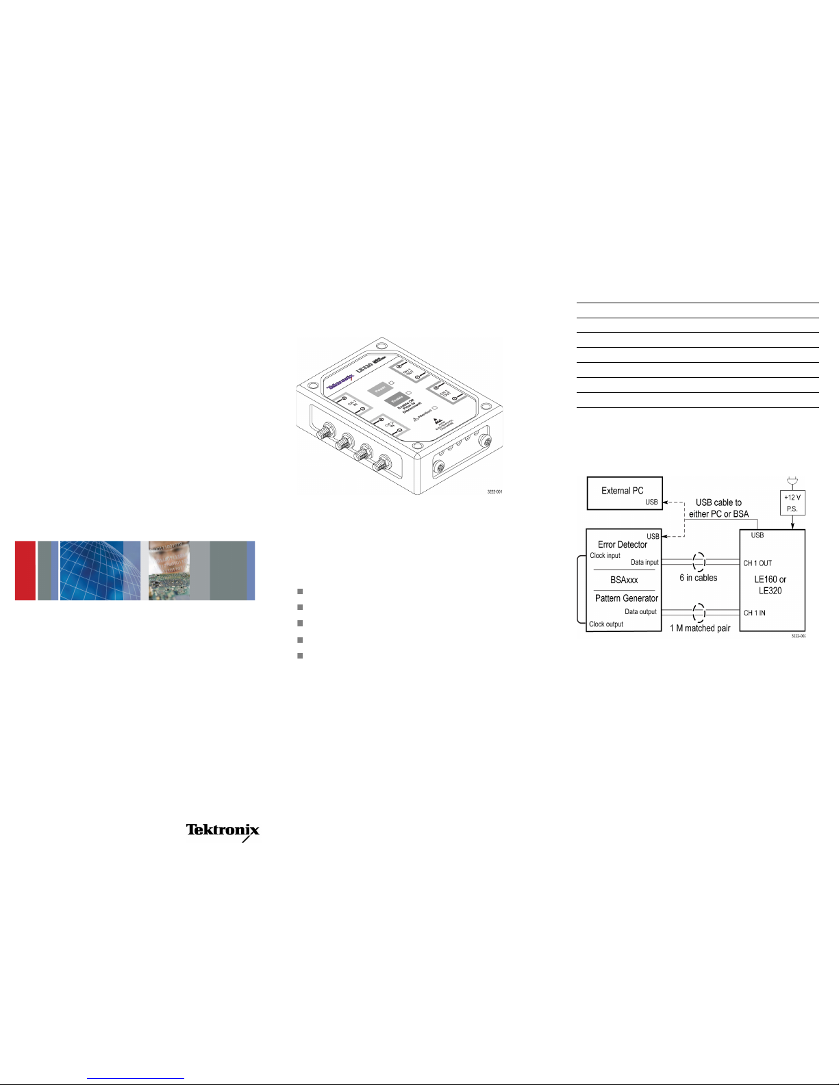
Make the hardware connections
Refer to the instrument connection diagram shown below when
doing the following steps.
1.
Using the 6 in, 2.92 mm cables, connect the CH 1 output
from the linear equalizer to the input of the BERTScope.
2.
Connect the data output from the BERTScope to the CH 1
differential input on the linear equalizer.
3.
On the BSA instrument, connect the Clk out from the
pattern generator to the Clk in on the error detector.
4.
Insert the mini-B end of the USB cable into the
USB-mini-B connector on the linear equalizer. Connect
the other end of the cable into the USB-A connector on the
BERTScope (or PC, if using as the controller).
5.
Connect the power supply to the linear equalizer.
Note: The power supply must be connected to warrant
proper operation.
6.
Power on all of the equipment and allow it to warm up
for 20 m inutes.
LE160 & LE320
Linear Equalizers
Testing Application
ZZZ
Installation Instructions
x
*P071322200*
071-3222-00
Page 2

Load the BERTScope software
The BERTScope or PC must be loaded with Linear Equalizer
application software. To load the software, do the following:
1.
Go to the Tektronix Web site at www.tek.com.
2.
Enter
Linear Equalizer
in the search field and clickGo.
3.
Locate and double-click the link for the LE application
software.
4.
Follow the on-screen instructions to download and install
the software.
5.
After a successful install, test the functionality using the
procedure below.
Verify test functionality
1.
Make the following settings on the BSA pattern generator:
17 GHz
PRBS-7
Clock 1.0 V
Data 500 mV
2.
Launch the Linear Equalizer application.
3.
Set the display to eye mode.
4.
Look for jitter and an eye pattern @16 Gb; signal presence
indicates that the settings will work for the LE160, LE320
and other BSA instruments.
5.
Verify that you can connect to the LE using the GUI
Connect
button.
6.
On the 4-tap panel, select the
16Gbps_0dB_Setup
from
the drop-down list and then click the
LOAD
button as
shown.
7.
Enable the BertScope channel and make the following
settings:
CH1toLE320CH1+
CH2toLE320CH1–
Horizontal: 20 ps/div
8.
Set the BSA scope data output level to 250 mV
pp
.
9.
The screen shot below shows the expected open eye and
parameters.
NOTE.
For an optimal eye display, you may need to adjust the
taps to account for unit-to-unit and cabling setup variations.
Safety and compliance information
Use only the power supply provided with the product.
Use of
other power supplies may damage the product.
Refer to the complete safety information before using this
product.
Read the safety information in the instruction manual,
on the CD included with the product.
EMC information and requirements.
This product is intended
for use in non-residential areas only. Use in residential areas
may cause electromagnetic interference.
Emissions that exceed the limits of applicable EMC standards
may occur when the equipment is connected to a test object.
Interface cables attached to this instrument must be of high
quality, shielded construction to ensure compliance with
regulatory EMC requirements.
Equipment Recycling.
This product complies
with the European Union’s requirements according
to Directive 2002/96/EC on waste electrical
and electronic equipment (WEEE). For more
information about recycling options, check the
Support/Service section of the Tektronix Web site
(www.tektronix.com).
Contacting Tektronix
Web site: www.tektronix.com
Phone: 1-800-833-9200
Address: Tektronix, Inc.
Technical Support Center
14200 SW Karl Braun Drive
P.O . B o x 5 0 0
Beaverton, OR 97077
USA
Email:
techsupport@tektronix.com
Warranty Information
For warranty information, go to www.tektronix.com/warranty
Copyright © Tektronix, Inc. All rights reserved. www.tektronix.com
 Loading...