

Page 1

Keithley Instruments
KTTI-RS232 Communication and Digital I/O
28775 Aurora Road
Cleveland, Ohio 44139
1-800-935-5595
tek.com/keithley
Accessory Instruction Sheet
Introduction
The KTTI-RS232 Communication and Digital I/O Accessory provides instruments with an accessory card slot
with an RS-232 interface.
The card provides six independently configurable digital input/output lines that can be used to control external
digital circuitry, for example, a handler that is used to perform binning operations. The digital I/O port is a
standard female DB-9 connector. You can also use these lines for triggering. The instrument can generate
output trigger pulses and detect input trigger pulses.
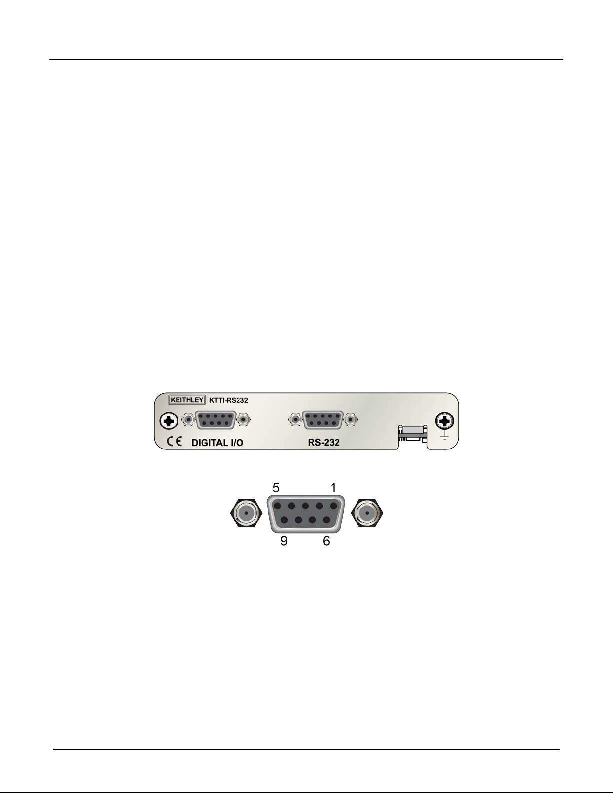
Figure 1: KTTI-RS232 communications card
077143600 / April 2018 *P077143600* 1
The item shipped may vary from model pictured.
Page 2

KTTI-RS232 Communication and Digital I/O Accessory Instruction Sheet
General specifications
General ratings for the KTTI-RS232 are lis ted in the fol low ing tab le.
Category Specification
Serial interface I/O connector: DB-9, female connector
Compliance Conforms to European Union EMC Directive
Compliance with CE and NRTL listed to UL61010-1 and UL61010-2-30
Conforms with European Union Low Voltage Directive
Environmental conditions I/O connector: DB-9, female connector
Operating temperature: 0 °C (32 °F) to 55 °C (131 °F)
Storage temperature: –20 °C (–4 °F) to 80 °C (176 °F)
Relative humidity: 5% to 95%, noncondensing
Power consumption: +5.0 V: 250 mA (typical), 300 mA (maximum)
Dimensions, (not including connectors): 120 mm (4.72 in.) x 64.5 mm
(2.54 in.)
Digital I/O Connector: 9-pin female D.
5V Power Supply Pin: Limited to 500 mA at > 4 V (solid-state fuse protected).
Lines: Six input/output, user-defined, for digital I/O or triggering.
Input Signal Levels: 0.7 V (maximum logic low), 3.7 V (minimum logic high).
Input Voltage Limits: –0.25 V (absolute minimum), +5.25 V (absolute
maximum).
Maximum Source Current: +2.0 mA at >2.7 V (per pin).
Maximum Sink Current: –50 mA at 0.7 V (per pin, solid-state fuse protected).
Environmental conditions Operating environment: Temperature 23 ºC ± 5 ºC, 5% to 80% relative
humidity, noncondensing
Storage environment: –25 ºC to 65 ºC
Unpack and inspect
Make sure to handle the KTTI-RS232 carefully. Always grasp the card by the side edges. Do not touch board
surfaces, components, or areas adjacent to electrical contacts. Contamination from foreign materials such as
dirt, dust, and body oils can substantially degrade card performance.
To unpack and inspect your instrumen t:
1. Inspect the box for damage.
2. Open the box.
3. Remove the card and inspect for any obvious signs of physical damage.
4. Report any damage to the shipping agent im mediately.
Installation
Slot covers must be installed on unused slots to prevent personal contact with high-voltage
circuits. Failure to recognize and observe standard safety precautions could result in
personal injury or death due to electric shock.
2 077143600 / April 2018
Page 3
KTTI-RS232 Communication and Digital I/O Accessory Instruction Sheet
To install the communications car d :
1. Turn the instrument off and disconnect the power line cord and any other cables connected to the rear
panel.
2. Position the instrument so that you are facing the rear panel.
3. Remove the slot cover plate from the slot on the back of the instrument. Retain the plate and screws for
future use.
4. Align the card with the connector toward the inside edge of the slot and slide the card into the chassis. For
the last ¼ inch, press in firmly to mate the card to the connector.
5. On each side of the card, there is a spring-loaded mounting screw. Tighten these two screws, either by
hand or with a Phillips-head screwdriver, to secure the card in the case. Do not overtighten.
6. Reconnect the power line cable and any other cables to the rear panel.
7. Turn on the instrument.
Making connections
The RS-232 serial port can be connected to the serial port of a controller using a straight-through RS232 cable
terminated with DB-9 connectors. Do not use a null modem cable.
The serial port uses the transmit (TXD), receive (RXD), and signal ground (GND) lines of the RS232 standard.
The figure below shows the rear panel connector for the RS232 interface. The table below shows the pinouts
for the connector.
Figure 2: KTTI-RS232 panel view
Figure 3: RS-232 panel connector
077143600 / April 2018 3
Page 4
KTTI-RS232 Communication and Digital I/O Accessory Instruction Sheet
Pin Description
1 No connection
2 TXD, transmit data
3 RXD, receive data
4 No connection
5 GND, signal ground
6 No connection
7 No connection
8 No connection
9 No connection
Operation
This section provides information needed to use the KTTI-RS232.
When the communications card is installed, the instrument recognizes the card when the power is turned on.
The KTTI-RS232 interface transfers data using eight data bits, one stop bit, and no parity. Make sure the
device you connect to the instrument also uses these settings .
You can break data transmissions by sending the ^C or ^X character string. This clears any pending operations
and discards any pending output.
Refer to the instrument reference manual for information about controlling the instrument from a remote
interface.
4 077143600 / April 2018
Page 5

KTTI-RS232 Communication and Digital I/O Accessory Instruction Sheet
Configuration
The baud rate is the rate at which the instrument and the attached device communicate. The factory-selected
baud rate is 9600, but you can choose from any of these available rates.
115200
57600
38400
19200
9600
4800
2400
1200
600
300
When you choose a baud rate, make sure the attached device can support the selected rate. The instrument
and the attached device must be configured for the same baud rate.
To configure the RS-232 card:
1. Press the MENU key.
2. Select Communication.
3. Set the Baud Rate option.
4. Set Flow Control.
Digital I/O
The KTTI-RS232 digital I/O port provides six independently configurable digital input/output lines.
You can use these lines for digital control by writing a bit pattern to the digital I/O lines. Digital control is used
for applications such as providing binning codes to a component handler. Digital control uses the state of the
line to determine the action to take.
You can also use these lines for triggering by using the transition of the line state to initiate an action. The
instrument can generate output trigger pulses and detect input trigger pulses. Triggering is used for applications
such as synchronizing the operations of a measurement instrument with the operations of other instruments.
You cannot configure or directly control the digital I/O lines from the front panel. To configure and control any of
the six digital input/output lines, you need to send commands to the KTTI-RS232 over a remote interface. You
can use either the SCPI or TSP command set.
See Remote communications interfaces in the instrument reference manual for information about setting up a
remote interface and choosing a command set.
077143600 / April 2018 5
Page 6
KTTI-RS232 Communication and Digital I/O Accessory Instruction Sheet
Digital I/O connector and pinout s
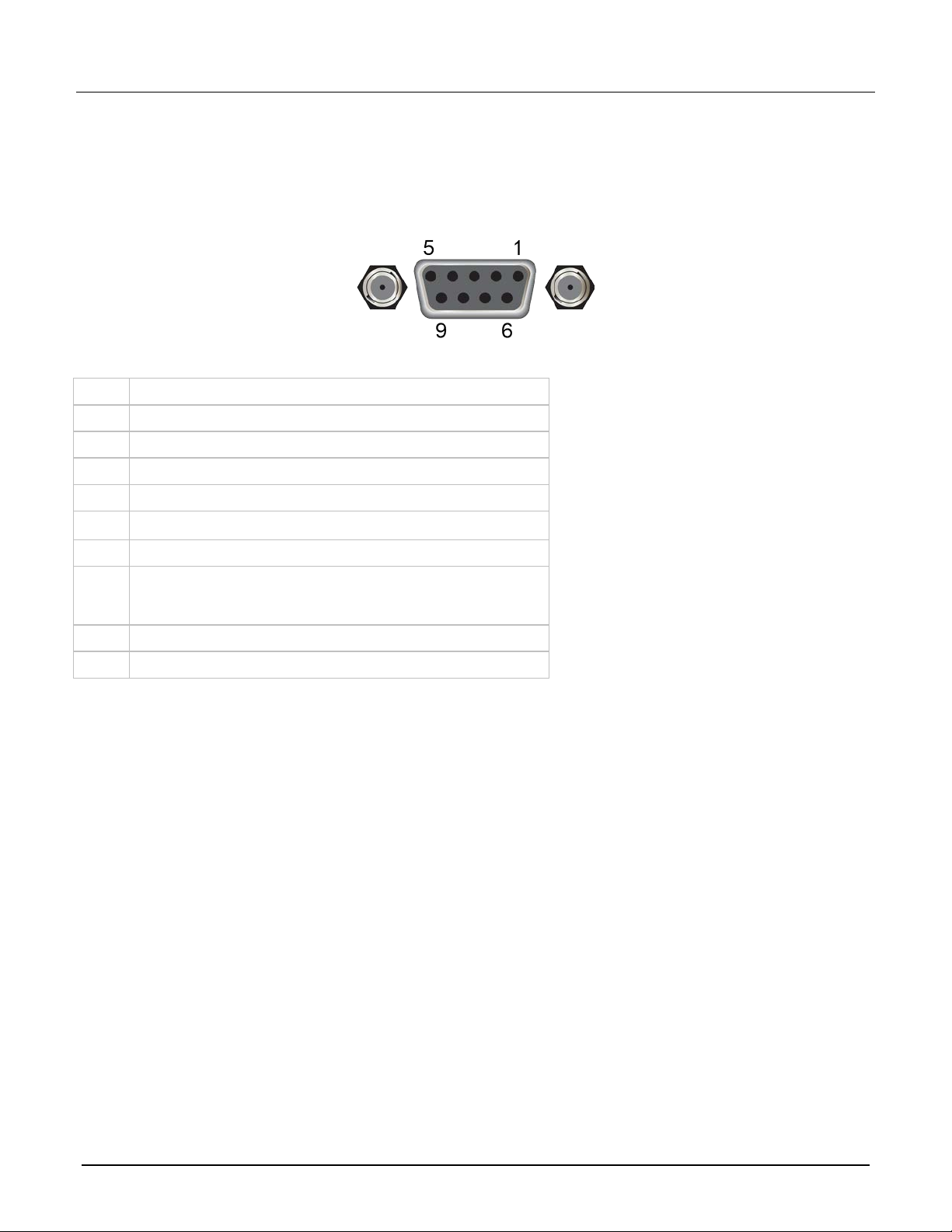
The digital I/O port uses a standard female DB-9 connector, located on the rear panel of the KTTI-RS232. You
can connect to the KTTI-RS232 digital I/O using a standard male DB-9 connector. The port provides a
connection point to each of the six digital I/O lines and other connections, as shown in the following table.
Figure 4: Digital I/O communication port
KTTI-RS232 digital I/O port pinouts
Pin Description
1 I/O line #1
2 I/O line #2
3 I/O line #3
4 I/O line #4
5
6 I/O line #5
7 +5 V line. Use this pin to drive external logic circuitry. Maximum
8 I/O line #6
9 Ground
line (relay flyback diode protection; maximum 33 V)
V
ext
current output is 500 mA. This line is protected by a
self-resetting fuse (one-hour recovery time).
6 077143600 / April 2018
Page 7

KTTI-RS232 Communication and Digital I/O Accessory Instruction Sheet
Digital I/O port configura t ion
The following figure shows the basic configuration of the digital I/O port.
To set a line high (nominally +5 V), write a 1 to it; to set a line low (nominally 0 V), write a 0 to it. To allow a
external device to control the state of the line, the line must be set to input mode or open-drain mode. An
attached device must be able to sink at least 50 µA from each I/O line.
F
igure 5: Digital I/O port configuration
n
For additional details about the digital output, see the KTTI-RS232 specifications, available at the
Keithley Instruments support website
.
077143600 / April 2018 7
Page 8

KTTI-RS232 Communication and Digital I/O Accessory Instruction Sheet
Vext line
The digital I/O port provides a line (V
) with a flyback diode clamp that you can use when controlling inductive
ext
circuitry such as relay coils or low-power solenoids. You can use the built-in 5 V supply or an external vo lta g e
supply for these types of applications. The externally supplied voltage can be up to +33 V.
Do not apply more than 50 mA (maximum current) or exce ed +33 V (maximum voltage) on the
digital I/O lines. Applying current or voltage exceeding these limits may damage the
instrument.
Refer to the following figure for a simplified schematic of a sample control circuit for a relay. You can externally
power a different device by replacing the relay coil with the other device. The relay is actuated by configuring
the corresponding digital output line. Most of these types of applications use an active-low (set the bit to 0) to
turn the relay on (ON = 0 V). In the low state (0 V), the output transistor sinks current through the external
device. In the high state, the output transistor is off (transistor switch is open). This interrupts current flow
through the external device.
igure 6: Digital I/O port (example external circuit)
F
+5 V line
The digital I/O port provides a +5 V output. You can use this line to drive external circuitry. The maximum
current output for this line is 500 mA. A self-resetting fuse with a one-hour recovery time protects this line.
If you are using this supply to drive a relay, it should be connected to the V
by the flyback diode clamp.
8 077143600 / April 2018
line so that the relay is protected
ext
Page 9

KTTI-RS232 Communication and Digital I/O Accessory Instruction Sheet
Digital I/O lines
You can place each digital I/O line into one of the following modes:
Digital open-drain, output, or input
Trigger open-drain, output, or input
Trigger synchronous master or acceptor
When you configure the digital I/O lines for triggering applications, configure the output lines before
the input lines. This prevents possible false input trigger detection in certain situations.
Digital control modes
If you are setting a line for digital control, you can set the line to be open-drain, output, or input, as described in
the following topics.
Open-drain
When you place a line in open-drain mode, the line is configured to be an open-drain signal with a 100 kΩ
pull-up resistor. This makes the line compatible with other instruments that use open-drain digital I/O lines, such
as other Keithley Instruments products that only support open-drain for its digital I/O. In this mode, the line can
serve as an input, an output, or both. You can read from the line or write to it. When a digital I/O line is used as
an input in open-drain mode, you must write a 1 to the line to enable it to detect logic levels that are generate
f
rom external sources.
d
Output
When you place a line in output mode, you can set the line as logic high (+5 V) or as logic low (0 V). The
default level is logic low (0 V). When the instrument is in output mode, the line is actively driven high or low.
Unlike the input or open-drain modes, it will not respond to externally generated logic levels.
When you read the line, it shows the present output status and an event message is generated.
Input
The input mode is similar to the open-drain mode, except that a line in this mode is intended to be used strictly
as an input. When you place a line in input mode, the instrument automatically writes a 1 to the line to enable it
to detect externally generated logic levels.
You can read an input line, but you cannot write to it. You also cannot change the logic level while the line is in
input mode. If you attempt to change the logic level of a line that is in input mode, an event message is
generated.
077143600 / April 2018 9
Page 10

KTTI-RS232 Communication and Digital I/O Accessory Instruction Sheet
Trigger control modes
You can use the trigger control modes to synchronize instrument operation with the operation of other
instruments. These modes either detect or generate transitions in the state of the line, from high to low (falling
edge) or from low to high (rising edge). The input edge detection setting of the instrument determines which
type of transition is detected as an input trigger. Output triggers are typically generated in the form of a pulse.
The type of transition that occurs on the leading edge of the pulse is determined by an output logic setting. The
duration of the pulse is determined by a pulse width setting.
You can use the trigger control modes with interactive triggering or with the trigger model. For more information
about the trigger modes and triggering, refer to the triggering section of the instrument reference manual.
Open-drain
When you set the instrument to trigger mode and place a line in open-drain mode, the line is configured to be
an open-drain signal with a 100 kΩ pull-up resistor. This makes the line compatible with other instruments that
use open-drain trigger signals, such as other Keithley Instruments products that only support open-drain for its
digital I/O. In this mode, you can use the line to detect input triggers or generate output triggers, or both. To use
this mode successfully, you must carefully configure the input edge and output logic settings because both of
these affect the initial state of the trigger line. It is recommended that you reset the line before selecting and
configuring this mode.
To use the line only as a trigger input:
1. Reset the line.
2. Set the input trigger edge detection type to falling, rising, or either.
The command that sets the detection type automatically sets the line high. This enables the line to respond to
and detect externally generated trigg er s .
Do not set the output trigger logic type to positive after setting the edge detection type. This sets the line low,
which will prevent the line from operating correctly as a trigger input.
To use the line only as a trigger output:
1. Reset the line.
2. Set the output trigger logic type to negative (falling edge) or positive (rising edge).
When you set the logic type to negative, the instrument automatically sets the line high. Setting the logic type to
positive automatically sets the line low.
Do not set the input trigger edge detection type after setting the positive logic type. This will set the line high,
which will prevent the line from operating correctly as a trigger output.
To use the line as both a trigger input and a trigger output (falling edge triggers on ly):
1. Reset the line.
2. Set the output trigger logic type to negative (falling edge).
3. Set the input trigger edge detection type to falling, rising, or either.
You can use these settings for triggering applications that use Keithley Instrument products featuring Trigger
Link.
Output
When you place a line in output mode, it is autom atically set high or low depending on the output logic setting .
Use the negative logic setting when you want to generate a falling edge trigger. Use the positive logic setting
when you want to generate a rising edge trigger. You cannot detect incoming triggers on a line configured as a
trigger output.
10 077143600 / April 2018
Page 11

KTTI-RS232 Communication and Digital I/O Accessory Instruction Sheet
Input
When you place a line in input mode, it is automatically set high to allow it to respond to and detect externally
generated triggers. Depending on the input edge detection setting, the line can detect falling-edge triggers,
rising-edge triggers, or both.
The line cannot generate an output trigger if it is set to the trigger input mode.
Synchronous triggering
The synchronous triggering modes allow you to:
Implement bidirectional triggering on a single trigger line
Start operations on one or more external instruments using a single trigger line
Wait for all instruments to complete all triggered actions
To coordinate non-Keithley instrumentation with synchronous triggering, the non-Keithley instrument must have
a trigger mode that is similar to the synchronous acceptor or synchronous master trigger mode.
To use synchronous triggering, configure the triggering master to synchronous master trigger mode or the
non-Keithley equivalent. Configure all other instruments in the test system to the synchronous acceptor trigger
mode or equivalent.
Synchronous master
Use the synchronous master trigger mode with the synchronous acceptor mode or its non-Keithley equivalent.
Configure only one instrument as a synchronous master. Configure all other instruments that are connected to
the synchronization line as synchronous acceptors.
When a digital I/O line is set to the synchronous master mode, it generates falling edge output triggers and
detects rising edge input triggers on the same trigger line.
Instruments that are configured as synchronous acceptors detect the falling-edge trigger and begin their
triggered actions. At the same time, they latch the line low and hold it in that state until their trigg ered ac tio ns
complete. Each instrument configured as an acceptor releases the line upon completion of its triggered actions.
When all instruments have released the line, the line changes state and generates a rising edge trigger. This
trigger is detected by the synchronous master, which then performs its next triggered action.
077143600 / April 2018 11
Page 12

KTTI-RS232 Communication and Digital I/O Accessory Instruction Sheet
Input characteristics:
All rising edges are input triggers.
When all external drives release the physical line, the rising edge is detected as an input trigger.
A rising edge is not detected until all external drives release the line and the line floats high.
Figure 7: Synchronous master input trigger
Output characteristics:
In addition to trigger events from other trigger objects, the TSP comm
ger.digout[N].assert() generates a low pulse that is similar to the falling-edge trigger mode.
trig
An action overrun occurs if the physical line state is low when a stimulus event occurs.
Figure 8: Synchronous master output trigger
Synchronous acceptor
Use the synchronous acceptor trigger mode with the synchronous master mode or its non-Keithley equivalent.
Only one instrument should be configured as a synchronous master. All other instruments connected to the
synchronization line must be configured as synchronous acceptor or equivalent.
and
A line that is set to the synchronous acceptor mode detects falling edge input triggers and generates rising
edge output triggers on the same trigger line. When a line that is configured as synchronous acceptor detects
the falling edge trigger, it latches the line low and holds it in that state until all triggered actions for that
instrument are complete. When the triggered actions are complete, the synchronous acceptor line releases the
line. When all connected instruments have released the line, the line changes state and generates a rising
edge trigger.
12 077143600 / April 2018
Page 13

Input characteristics:
KTTI-RS232 Communication and Digital I/O Accessory Instruction Sheet
The falling edge is detected as the external drive pulses the line low, and the internal drive latches the li
l
ow.
Figure 9: Synchronous acceptor input tri g ger
Output characteristics:
In addition to trigger events from other trigger objects, the TSP comm
trigger.digout[
The physical line state does not change until all drives (internal and external) release the line.
Action overruns occur if the internal drive is not latched low and a source event is received.
N].assert() triggers events as well.
Figure 10: Synchronous acceptor output trigger
and
ne
077143600 / April 2018 13
Page 14

KTTI-RS232 Communication and Digital I/O Accessory Instruction Sheet
:DIGital:LINE<n>:MODE
*RST
:DIGital:LINE<n>:STATe
:DIGital:READ?
:DIGital:WRITe <n>
:TRIGger:DIGital<n>:IN:CLEar
:TRIGger:DIGital<n>:IN:EDGE
:TRIGger:DIGital<n>:IN:OVERrun?
trigger.digout[N].assert()
Remote digital I/O comma nds
Commands for both SCPI and TSP are summarized in the following table. You can use the digital I/O port to
perform the following actions:
Perform basic steady-state digital I/O operations, suc h as readi ng and writing to indi vidua l I/O lines or
reading and writing to the entire port
Trigger the instrument when external trigger pulses are applied to the digital I/O port
Provide trigger pulses to external devices
For detailed descriptions and sample applications, see the instrument reference manual.
SCPI command
TSP command Description
This command sets the mode of the digital I/O line
digio.line[N].mode
to be a digital line, trigger line, or synchronous line
and sets the line to be input, output, or open-drain.
A line reset is not available in SCPI; however, the line
is reset when a global reset (
) is sent
digio.line[N].reset()
digio.line[N].state
digio.readport()
digio.writeport()
trigger.digin[N].clear()
trigger.digin[N].edge
This command resets digital I/O line values to their
factory defaults.
This command sets a digital I/O line high or low
when the line is set for digital control and returns
the state on the digital I/O lines.
This command reads the digital I/O port. All six lines
must be configured as digital control lines. If not,
this command generates an error.
This command writes to all digital I/O lines. All six
lines must be configured as digital control lines. If
not, this command generates an error.
This command clears the trigger event on a digital
input line.
This command sets the edge used by the trigger
event detector on the given trigger line.
trigger.digin[N].overrun
Not available in SCPI This command waits for a trigger.
trigger.digin[N].wait()
Not available in SCPI This command asserts a trigger pulse on one of the
14 077143600 / April 2018
This command returns the event detector overrun
status.
digital I/O lines.
Page 15

KTTI-RS232 Communication and Digital I/O Accessory Instruction Sheet
:TRIGger:DIGital<n>:OUT:LOGic
:TRIGger:DIGital<n>:OUT:PULSewidth
:TRIGger:DIGital<n>:OUT:STIMulus
SCPI command
TSP command Description
This command sets the output logic of the trigger
trigger.digout[N].logic
trigger.digout[N].pulsewidth
Not available in SCPI This command releases an indefinite length or
trigger.digout[N].release()
trigger.digout[N].stimulus
event generator to positive or negative for the
specified line.
This command describes the length of time that the
trigger line is asserted for output triggers.
latched trigger.
This command selects the event that causes a
trigger to be asserted on the digital output line.
To use the trigger model as a stimulus to a digital I/O line, you can use the trigger model Notify
block. For information on the Notify block, see the reference manual for your instrument.
Digital I/O bit weighting
Bit weighting for the digital I/O lines is shown in the following table. Line 1 is the least significant bit.
Line # Bit Pin Decimal Hexadecimal Binary
1 B1 1 1 0x01 000001
2 B2 2 2 0x02 000010
3 B3 3 4 0x04 000100
4 B4 4 8 0x08 001000
5 B5 6 16 0x10 010000
6 B6 8 32 0x20 100000
Digital I/O programming examples
These examples provide typical methods you can use to work with the digital I/O port.
Outputting a bit pattern
The programming examples below illustrate how to output the bit pattern 110101 at the digital I/O port. Line 1
(bit 1) is the least significant bit.
077143600 / April 2018 15
Page 16

KTTI-RS232 Communication and Digital I/O Accessory Instruction Sheet
Using SCPI commands to configure all six lines as digital outputs:
:DIGital:LINE1:MODE DIGital, OUT
:DIGital:LINE2:MODE DIGital, OUT
:DIGital:LINE3:MODE DIGital, OUT
:DIGital:LINE4:MODE DIGital, OUT
:DIGital:LINE5:MODE DIGital, OUT
:DIGital:LINE6:MODE DIGital, OUT
Using SCPI commands to set the state of each line individually:
:DIGital:LINE6:STATe 1
:DIGital:LINE5:STATe 1
:DIGital:LINE4:STATe 0
:DIGital:LINE3:STATe 1
:DIGital:LINE2:STATe 0
:DIGital:LINE1:STATe 1
Using SCPI commands to set all six lines at onc e by writing the decimal equivalent of the bit pattern to
the port:
:DIGital:WRITe 53
Using TSP commands to configure all six lines a s digital outputs:
-- Send for loop as a single chunk or include in a script.
for i = 1, 6 do
digio.line[i].mode = digio.MODE_DIGITAL_OUT
end
Using TSP commands to set the state of each line individually:
digio.line[1].state = digio.STATE_HIGH
digio.line[2].state = digio.STATE_LOW
digio.line[3].state = digio.STATE_HIGH
-- You can use 0 instead of digio.STATE_LOW.
digio.line[4].state = 0
-- You can use 1 instead of digio.STATE_HIGH.
digio.line[5].state = 1
digio.line[6].state = 1
Using TSP commands to set all six lines at once by writing the decimal equivalent of the bit pattern to
the port:
-- You can write binary, decimal or hexadecimal values, as shown below.
-- Use binary value.
digio.writeport(0b110101)
-- Use decimal value.
digio.writeport(53)
-- Use hexadecimal value.
digio.writeport(0x35)
16 077143600 / April 2018
Page 17

KTTI-RS232 Communication and Digital I/O Accessory Instruction Sheet
Reading a bit pattern
The programming examples below illustrate how to read part or all of a bit pattern that has been applied to the
digital I/O port by an external instrument. The binary pattern is 111111 (63 decimal). Line 1 (bit 1) is the least
significant bit.
Using SCPI commands:
Configure all six lines as digital inputs:
DIGital:LINE1:MODE DIGital, IN
DIGital:LINE2:MODE DIGital, IN
DIGital:LINE3:MODE DIGital, IN
DIGital:LINE4:MODE DIGital, IN
DIGital:LINE5:MODE DIGital, IN
DIGital:LINE6:MODE DIGital, IN
Read the state of Line 2:
DIGital:LINE2:STATe?
Value returned is 1.
Read the state of Line 3:
DIGital:LINE3:STATe?
Value returned is 1.
Read the value applied to the entire port:
DIGital:READ?
Value returned is 63, which is the decimal equivalent of the binary bit pattern.
Using TSP commands:
-- Configure all six digital I/O lines as digital inputs.
-- You can also use a for loop.
digio.line[1].mode = digio.MODE_DIGITAL_IN
digio.line[2].mode = digio.MODE_DIGITAL_IN
digio.line[3].mode = digio.MODE_DIGITAL_IN
digio.line[4].mode = digio.MODE_DIGITAL_IN
digio.line[5].mode = digio.MODE_DIGITAL_IN
digio.line[6].mode = digio.MODE_DIGITAL_IN
-- Read and then print the state of Line 2 (bit 2).
b2 = digio.line[2].state
print(b2)
The value returned is digio.STATE_HIGH.
-- Print the state of Line 3 (bit 3).
print(digio.line[3].state)
The value returned is digio.STATE_HIGH.
-- Read and then print the value applied to the entire port.
port = digio.readport()
print(port)
The value returned is 63, which is the decimal equivalent of the binary bit pattern.
077143600 / April 2018 17
Page 18

KTTI-RS232 Communication and Digital I/O Accessory Instruction Sheet
Upgrading the firmware
You will periodically update the instrument firmware. During the upgrade pr oces s , the instr ument verifies that
the version you are loading is newer than what is on the instrument. If the version is older or at the same
revision level, no changes are made.
If you have a KTTI-RS232 communications accessory card installed in the instrument, the firmware on the card
is upgraded.
You can load the file from the front-panel USB port or you can use Test Script Builder (TSB) using a file saved
to the computer on which TSB is running.
The firmware file must be in the root subdirectory of the flash drive and must be the only firmware file in that
location.
If you want to return to a previous version or reload the present version of the firmware, select Downgrade to
Older. This forces the instrument to load the firmware regardless of the version.
The upgrade process normally takes about five minutes.
Upgrade files are available on tek.com/keithley
.
Accessories
The KTTI-RS232 requires a shielded RS-232 cable with a male DB-9 connector at one end and a female DB-9
connector on the other (wired as a straight-through, not as a null modem cable).
Model 7009-5 1.5 m (5 ft), male DB-9 to female DB-9
18 077143600 / April 2018
Page 19

Safety precaut ions
The following safety precautions should be observed before using this produ ct and any associa ted ins t rum enta tion. Although
some instruments and accessories would normally be used with nonhazardous voltages, there are situations where hazardous
conditions may be present.
This product is intended for use by personnel who recognize shock hazards and are familiar with the safety precautions required
to avoid possible injury. Read and follow all installation, operation, and maintenance information carefully before using the
product. Refer to the user documentation for complete product specifications.
If the product is used in a manner not specified, the protection provided by the product warranty may be impaired.
The types of product users are:
Responsible body is the individual or group responsible for the use and maintenance of equipment, for ensuring that the
equipment is operated within its specifications and operating limits, and for ensuring that operators are adequately trained.
Operators use the product for its intended function. They must be trained in electrical safety procedures and proper use of the
instrument. They must be protected from electric shock and contact with hazardous live circuits.
Maintenance personnel perform routine procedures on the product to keep it operating properly, for example, setting the line
voltage or replacing consumable materials. Maintenance procedures are described in the user documentation. The procedures
explicitly state if the operator may perform them. Otherwise, they should be performed only by service personnel.
Service personnel are trained to work on live circuits, perform safe installations, and repair products. Only properly trained
service personnel may perform installation and service procedures.
Keithley products are designed for use with electrical signals that are measurement, control, and data I/O connections, with low
transient overvoltages, and must not be directly connected to mains voltage or to voltage sources with high transient
overvoltages. Measurement Category II (as referenced in IEC 60664) connections require protection for high transient
overvoltages often associated with local AC mains connections. Certain Keithley measuring instruments may be connected to
mains. These instruments will be marked as category II or higher.
Unless explicitly allowed in the specifications, operating manual, and instrument labels, do not connect any instrument to mains.
Exercise extreme caution when a shock hazard is present. Lethal voltage may be present on cable connector jacks or test
fixtures. The American National Standards Institute (ANSI) states that a shock hazard exists when voltage levels greater than
30 V RMS, 42.4 V peak, or 60 VDC are present. A good safety practice is to expect that hazardous voltage is present in any
unknown circuit before measuring.
Operators of this product must be protected from electric shock at all times. The responsible body must ensure that operators
are prevented access and/or insulated from every connection point. In some cases, connections must be exposed to potential
human contact. Product operators in these circumstances must be trained to protect themselves from the risk of electric shock. If
the circuit is capable of operating at or above 1000 V, no conductive part of the circ uit may be ex posed.
For maximum safety, do not touch the product, test cables, or any other instruments while power is applied to the circuit under
test. ALWAYS remove power from the entire test system and discharge any capacitors before: connecting or disconnecting
cables or jumpers, installing or removing switching cards, or making internal changes, such as installing or removing jumpers.
Do not touch any object that could provide a current path to the common side of the circuit under test or power line (earth)
ground. Always make measurements with dry hands while standing on a dry, insulated surface capable of withstanding the
voltage being measured.
For safety, instruments and accessories must be used in accordance with the operating instructions. If the instruments or
accessories are used in a manner not specified in the operating instructions, the protection provided by the equipment may be
impaired.
Do not exceed the maximum signal levels of the instruments and accessories. Maximum signal levels are defined in the
specifications and operating information and shown on the instrument panels, test fixture panels, and switching cards.
Chassis connections must only be used as shield connections for measuring circuits, NOT as protective earth (safety ground)
connections.
The WARNING heading in the user documentation explains hazards that might result in personal injury or death. Always read
the associated information very carefully before performing the indicated procedure.
077143600 / April 2018 19
Page 20

The CAUTION heading in the user documentation explains h az ards that coul d dama ge the instrument. Such damage may
invalidate the warranty.
The CAUTION heading with the symbol in the user documentation explains hazards that could result in moderate or minor
injury or damage the instrument. Always read the associated information very carefully before performing the indicated
procedure. Damage to the instrument may invalidate the warranty.
Instrumentation and accessories shall not be connected to humans.
Before performing any maintenance, disconnect the line cord and all test cables.
To maintain protection from electric shock and fire, replacement components in mains circuits — including the power
transformer, test leads, and input jacks — must be purchased from Keithley. Standard fuses with applicable national safety
approvals may be used if the rating and type are the same. The detachable mains power cord provided with the instrument may
only be replaced with a similarly rated power cord. Other components that are not safety-related may be purchased from other
suppliers as long as they are equivalent to the original component (note that selected parts should be purchased only through
Keithley to maintain accuracy and functionality of the product). If you are unsure about the applicability of a replacement
component, call a Keithley office for information.
Unless otherwise noted in product-specific literature, Keithley instruments are designed to operate indoors only, in the following
environment: Altitude at or below 2,000 m (6,562 ft); temperature 0 °C to 50 °C (32 °F to 122 °F); and pollution degree 1 or 2.
To clean an instrument, use a cloth dampened with deionized water or mild, water-based cleaner. Clean the exterior of the
instrument only. Do not apply cleaner directly to the instrument or allow liquids to enter or spill on the instrument. Products that
consist of a circuit board with no case or chassis (e.g., a data acquisition board for installation into a computer) should never
require cleaning if handled according to instructions. If the board becomes contaminated and operation is affected, the board
should be returned to the factory for proper cleaning/servicing.
Safety precaution revision as of June 2017.
20 077143600 / April 2018
 Loading...