

Page 1

www.keithley.com
KPXI Digital Isolated Card
User’s Manual
KPXI-IDIO-900-01 Rev. A / January 2007
A GREATER MEASURE OF CONFIDENCE
ECA 42912
Page 2

WARRANTY
Keithley Instruments, Inc. warrants this product to be free from defects in material and workmanship for a period of
1 year from date of shipment.
Keithley Instruments, Inc. warrants the following items for 90 days from the date of shipment: probes, cables,
rechargeable batteries, diskettes, and documentation.
During the warranty period, we will, at our option, either repair or replace any product that proves to be defective.
To exercise this warranty, write or call your local Keithley Instruments representative, or contact
Keithley Instruments headquarters in Cleveland, Ohio. You will be given prompt assistance and return instructions.
Send the product, transportation prepaid, to the indicated service facility. Repairs will be made and the product
returned, transportation prepaid. Repaired or replaced products are warranted for the balance of the original
warranty period, or at least 90 days.
LIMITATION OF WARRANTY
This warranty does not apply to defects resulting from product modification without Keithley Instruments’ express
written consent, or misuse of any product or part. This warranty also does not apply to fuses, software,
non-rechargeable batteries, damage from battery leakage, or problems arising from normal wear or failure to follow
instructions.
THIS WARRANTY IS IN LIEU OF ALL OTHER WARRANTIES, EXPRESSED OR IMPLIED, INCLUDING ANY
IMPLIED WARRANTY OF MERCHANTABILITY OR FITNESS FOR A PARTICULAR USE. THE REMEDIES
PROVIDED HEREIN ARE BUYER’S SOLE AND EXCLUSIVE REMEDIES.
NEITHER KEITHLEY INSTRUMENTS, INC. NOR ANY OF ITS EMPLOYEES SHALL BE LIABLE FOR ANY
DIRECT, INDIRECT, SPECIAL, INCIDENTAL OR CONSEQUENTIAL DAMAGES ARISING OUT OF THE USE OF
ITS INSTRUMENTS AND SOFTWARE EVEN IF KEITHLEY INSTRUMENTS, INC., HAS BEEN ADVISED IN
ADVANCE OF THE POSSIBILITY OF SUCH DAMAGES. SUCH EXCLUDED DAMAGES SHALL INCLUDE, BUT
ARE NOT LIMITED TO: COSTS OF REMOVAL AND INSTALLATION, LOSSES SUSTAINED AS THE RESULT
OF INJURY TO ANY PERSON, OR DAMAGE TO PROPERTY.
A G R E A T E R M E A S U R E O F C O N F I D E N C E
Keithley Instruments, Inc.
Corporate Headquarters • 28775 Aurora Road • Cleveland, Ohio 44139
440-248-0400 • Fax: 440-248-6168 • 1-888-KEITHLEY (534-8453) • www.keithley.com
12/06
Page 3

KPXI
Digital Isolated Card
User’s Manual
©2007, Keithley Instruments, Inc.
Document Number:
All rights reserved.
Cleveland, Ohio, U.S.A.
KPXI-IDIO-900-01 Rev. A / January 2007
Page 4

Manual Print History KPXI Digital Isolated Card User’s Manual
Manual Print History
The print history shown below lists the printing dates of all Revisions and Addenda created for this
manual. The Revision Level letter increases alphabetically as the manual undergoes subsequent
updates. Addenda, which are released between Revisions, contain important change information that
the user should incorporate immediately into the manual. Addenda are numbered sequentially. When a
new Revision is created, all Addenda associated with the previous Revision of the manual are
incorporated into the new Revision of the manual. Each new Revision includes a revised copy of this
print history page.
Revision A (Document Number KPXI-IDIO-900-01) ...........................................January 2007
All Keithley Instruments product names are trademarks or registered trademarks of Keithley Instruments, Inc.
Other brand names are trademarks or registered trademarks of their respective holders.
KPXI-IDIO-900-01 Rev. A / January 2007
Page 5

The following safety precautions should be observed before using this product and any associated instrumentation. Although
some instruments and accessories would normally be used with non-hazardous voltages, there are situations where hazardous
conditions may be present.
This product is intended for use by qualified personnel who recognize shock hazards and are familiar with the safety precautions
required to avoid possible injury. Read and follow all installation, operation, and maintenance information carefully before using
the product. Refer to the manual for complete product specifications.
If the product is used in a manner not specified, the protection provided by the product may be impaired.
The types of product users are:
Responsible body is the individual or group responsible for the use and maintenance of equipment, for ensuring that the
equipment is operated within its specifications and operating limits, and for ensuring that operators are adequately trained.
Operators use the product for its intended function. They must be trained in electrical safety procedures and proper use of the
instrument. They must be protected from electric shock and contact with hazardous live circuits.
Maintenance personnel perform routine procedures on the product to keep it operating properly, for example, setting the line
voltage or replacing consumable materials. Maintenance procedures are described in the manual. The procedures explicitly state
if the operator may perform them. Otherwise, they should be performed only by service personnel.
Safety Precautions
Service personnel are trained to work on live circuits, and perform safe installations and repairs of products. Only properly
trained service personnel may perform installation and service procedures.
Keithley Instruments products are designed for use with electrical signals that are rated Measurement Category I and
Measurement Category II, as described in the International Electrotechnical Commission (IEC) Standard IEC 60664. Most
measurement, control, and data I/O signals are Measurement Category I and must not be directly connected to mains voltage or
to voltage sources with high transient over-voltages. Measurement Category II connections require protection for high transient
over-voltages often associated with local AC mains connections. Assume all measurement, control, and data I/O connections are
for connection to Category I sources unless otherwise marked or described in the Manual.
Exercise extreme caution when a shock hazard is present. Lethal voltage may be present on cable connector jacks or test
fixtures. The American National Standards Institute (ANSI) states that a shock hazard exists when voltage levels greater than
30V RMS, 42.4V peak, or 60VDC are present. A good safety practice is to expect that hazardous voltage is present in any
unknown circuit before measuring.
Operators of this product must be protected from electric shock at all times. The responsible body must ensure that operators
are prevented access and/or insulated from every connection point. In some cases, connections must be exposed to potential
human contact. Product operators in these circumstances must be trained to protect themselves from the risk of electric shock.
If the circuit is capable of operating at or above 1000 volts, no conductive part of the circuit may be exposed.
Do not connect switching cards directly to unlimited power circuits. They are intended to be used with impedance limited sources.
NEVER connect switching cards directly to AC mains. When connecting sources to switching cards, install protective devices to
limit fault current and voltage to the card.
Before operating an instrument, make sure the line cord is connected to a properly grounded power receptacle. Inspect the
connecting cables, test leads, and jumpers for possible wear, cracks, or breaks before each use.
12/06
Page 6

When installing equipment where access to the main power cord is restricted, such as rack mounting, a separate main input
power disconnect device must be provided, in close proximity to the equipment and within easy reach of the operator.
For maximum safety, do not touch the product, test cables, or any other instruments while power is applied to the circuit under
test. ALWAYS remove power from the entire test system and discharge any capacitors before: connecting or disconnecting
cables or jumpers, installing or removing switching cards, or making internal changes, such as installing or removing jumpers.
Do not touch any object that could provide a current path to the common side of the circuit under test or power line (earth) ground.
Always make measurements with dry hands while standing on a dry, insulated surface capable of withstanding the voltage being
measured.
The instrument and accessories must be used in accordance with its specifications and operating instructions or the safety of the
equipment may be impaired.
Do not exceed the maximum signal levels of the instruments and accessories, as defined in the specifications and operating
information, and as shown on the instrument or test fixture panels, or switching card.
When fuses are used in a product, replace with same type and rating for continued protection against fire hazard.
Chassis connections must only be used as shield connections for measuring circuits, NOT as safety earth ground connections.
If you are using a test fixture, keep the lid closed while power is applied to the device under test. Safe operation requires the use
of a lid interlock.
If a screw is present, connect it to safety earth ground using the wire recommended in the user documentation.
!
The symbol on an instrument indicates that the user should refer to the operating instructions located in the manual.
The symbol on an instrument shows that it can source or measure 1000 volts or more, including the combined effect of
normal and common mode voltages. Use standard safety precautions to avoid personal contact with these voltages.
The symbol on an instrument shows that the surface may be hot. Avoid personal contact to prevent burns.
The symbol indicates a connection terminal to the equipment frame.
The WARNING heading in a manual explains dangers that might result in personal injury or death. Always read the associated
information very carefully before performing the indicated procedure.
The CAUTION heading in a manual explains hazards that could damage the instrument. Such damage may invalidate the
warranty.
Instrumentation and accessories shall not be connected to humans.
Before performing any maintenance, disconnect the line cord and all test cables.
To maintain protection from electric shock and fire, replacement components in mains circuits, including the power transformer,
test leads, and input jacks, must be purchased from Keithley Instruments. Standard fuses, with applicable national safety
approvals, may be used if the rating and type are the same. Other components that are not safety related may be purchased
from other suppliers as long as they are equivalent to the original component. (Note that selected parts should be purchased only
through Keithley Instruments to maintain accuracy and functionality of the product.) If you are unsure about the applicability of a
replacement component, call a Keithley Instruments office for information.
To clean an instrument, use a damp cloth or mild, water based cleaner. Clean the exterior of the instrument only. Do not apply
cleaner directly to the instrument or allow liquids to enter or spill on the instrument. Products that consist of a circuit board with
no case or chassis (e.g., data acquisition board for installation into a computer) should never require cleaning if handled
according to instructions. If the board becomes contaminated and operation is affected, the board should be returned to the
factory for proper cleaning/servicing.
Page 7

Table of Contents
Section Topic Page
1 Introduction............................................................................................. 1-1
Introduction ................................................................................................. 1-2
Features ............................................................................................... 1-2
Applications.......................................................................................... 1-3
Safety symbols and terms .......................................................................... 1-3
Specifications.............................................................................................. 1-3
Unpacking and inspection........................................................................... 1-3
Inspection for damage.......................................................................... 1-3
Shipment contents ............................................................................... 1-4
Instruction manual................................................................................ 1-4
Repacking for shipment........................................................................ 1-4
Supporting Software .................................................................................. 1-4
Programming Library............................................................................ 1-4
KDAQ-LVIEW LabVIEW® driver .......................................................... 1-5
2 Installation............................................................................................... 2-1
Introduction ................................................................................................. 2-2
Handling precautions .................................................................................. 2-2
PXI configuration ........................................................................................ 2-2
Plug and Play ....................................................................................... 2-2
Configuration........................................................................................ 2-2
Troubleshooting.................................................................................... 2-2
Installation................................................................................................... 2-2
3 Operation and connection................................................................... 3-1
Isolated digital input channels..................................................................... 3-2
KPXI-DIO-16-16 isolated digital output circuits........................................... 3-2
Isolated digital output channels .................................................................. 3-3
Connector pin assignment for KPXI-DIO-16-16.......................................... 3-4
Termination board connection..................................................................... 3-4
Connector pin assignment for KPXI-DIO-32-32.......................................... 3-5
Connector pin assignment of KPXI-DIO-64-0............................................. 3-6
Connector pin assignment of KPXI-DIO-0-64............................................. 3-7
4 Registers.................................................................................................. 4-1
Introduction ................................................................................................. 4-2
PCI PnP registers ....................................................................................... 4-2
I/O address map ......................................................................................... 4-2
Digital input register.................................................................................... 4-3
Digital output register.................................................................................. 4-4
Page 8

Table of Contents KPXI Digital Isolated Card User’s Manual
Appendix Topic Page
A KDIO-DRVR User’s Guide ................................................................... A-1
Introduction to KDIO-DRVR ....................................................................... A-2
About the KDIO-DRVR software.......................................................... A-2
KDIO-DRVR hardware support............................................................ A-2
KDIO-DRVR language support............................................................ A-2
KDIO-DRVR overview ................................................................................ A-3
General configuration function group .................................................. A-3
Actual sampling rate function group .................................................... A-4
Analog output function group............................................................... A-4
Digital input function group .................................................................. A-4
Digital output function group ................................................................ A-6
Timer/counter function group............................................................... A-7
DIO function group .............................................................................. A-8
Creating a KDIO-DRVR application ........................................................... A-9
Contiguous memory allocation in driver for continuous operation....... A-9
Fundamentals of building Windows XP/2000 Application.......................... A-9
Microsoft® Visual Basic (Version 6.0) .................................................. A-9
Using Microsoft Visual Basic.NET ...................................................... A-11
Microsoft Visual C/C++....................................................................... A-11
KDIO-DRVR application hints ................................................................... A-11
Digital input programming hints ......................................................... A-12
Digital output programming hints....................................................... A-17
DAQ event message programming hints........................................... A-21
Interrupt event message programming hints ..................................... A-22
Continuous data transfer in KDIO-DRVR ................................................. A-23
Continuous data transfer mechanism................................................ A-23
Double-buffered / multiple-buffered DI operation............................... A-23
KDIO-DRVR utilities for Win32................................................................. A-25
KDIO-DRVR configuration utility (configdrv)...................................... A-25
KDIO-DRVR data file converter utility (KIDAQCvt)............................ A-26
B KDIO-DRVR Function Reference....................................................... B-1
Function description................................................................................... B-2
Data types............................................................................................ B-2
Function reference............................................................................... B-2
Status Codes............................................................................................ B-38
Data file format......................................................................................... B-40
Header............................................................................................... B-40
ChannelRange................................................................................... B-41
Data Block ......................................................................................... B-42
Function Support...................................................................................... B-43
C KIDAQ®-LabVIEW Compatible Interface Guide............................. C-1
Introduction to KIDAQ®-LabVIEW ............................................................. C-2
Overview.............................................................................................. C-2
Using KIDAQ LabVIEW VIs in LabVIEW............................................. C-2
KIDAQ LabVIEW Programming........................................................... C-3
Device Driver Handling .............................................................................. C-4
Windows XP/2000 Device Driver......................................................... C-4
Driver Utility ......................................................................................... C-4
KIDAQ Utilities ........................................................................................... C-4
KIDAQ Registry/Configuration utility.................................................... C-4
KIDAQ Device Browser ....................................................................... C-4
KIDAQ LabVIEW VIs Overview.................................................................. C-5
Analog Input VIs .................................................................................. C-6
Analog Output VIs ............................................................................... C-6
Digital I/O VIs....................................................................................... C-7
Timer/Counter VIs................................................................................ C-7
Calibration and Configuration VIs........................................................ C-8
Error Handler VI................................................................................... C-8
ii KPXI-IDIO-900-01 Rev. A / January 2007
Page 9

KPXI Digital Isolated Card User’s Manual Table of Contents
Appendix Topic Page
C KIDAQ®-LabVIEW Compatible Interface Guide (continued)
Distribution of Applications......................................................................... C-8
Windows XP/2000 ............................................................................... C-8
D KIDAQ®-LabVIEW Compatible Function Reference..................... D-1
Introduction ................................................................................................ D-2
Hardware support....................................................................................... D-2
KPXI-DIO series: ................................................................................. D-2
KPXI-DAQ series: ................................................................................ D-2
Digitizer series: .................................................................................... D-2
Analog input VIs......................................................................................... D-3
Easy analog input VIs.......................................................................... D-3
Intermediate analog input VIs.............................................................. D-7
Analog output VIs..................................................................................... D-21
Easy analog output VIs...................................................................... D-21
Intermediate analog output VIs.......................................................... D-24
Advanced analog output VIs.............................................................. D-32
Digital I/O VIs ........................................................................................... D-33
Easy Digital I/O VIs............................................................................ D-33
Intermediate Digital I/O VIs................................................................ D-37
Advanced Digital I/O VIs.................................................................... D-45
Counter VIs .............................................................................................. D-46
Easy Counter VIs .............................................................................. D-46
Intermediate Counter VIs .................................................................. D-50
Advanced Counter VIs ...................................................................... D-63
Calibration and Configuration VIs ............................................................ D-67
Calibration VIs .................................................................................. D-67
Other Calibration and Configuration VIs............................................ D-68
Service VIs ............................................................................................... D-70
Error Codes ............................................................................................. D-71
AI Range Codes ...................................................................................... D-73
AI Data Format ....................................................................................... D-76
Service Form
KPXI-IDIO-900-01 Rev. A / January 2007 iii
Page 10

Table of Contents KPXI Digital Isolated Card User’s Manual
This page left blank intentionally.
iv KPXI-IDIO-900-01 Rev. A / January 2007
Page 11

List of Figures
Section Figure Title Page
2 Figure 2-1 Typical PXI module installation...................................................... 2-4
Figure 2-2 Device manager (successful installation) ...................................... 2-5
3 Figure 3-1 Isolated isolated input connections................................................ 3-2
Figure 3-2 Isolated digital output circuits wiring diagram ................................ 3-2
Figure 3-3 Common Ground Connection........................................................ 3-3
Figure 3-4 Common Power Connection.......................................................... 3-3
Appendix Figure Title Page
A Figure A-1 Open Project dialog box .............................................................. A-10
Figure A-2 Basic KDIO-DRVR building blocks .............................................. A-12
Figure A-3 One-shot digital input programming............................................. A-13
Figure A-4 Synchronous continuous digital input programming.................... A-14
Figure A-5 Non-multiple-buffered asynchronous continuous digital input ..... A-15
Figure A-6 Multiple-buffered asynchronous continuous digital input ............. A-16
Figure A-7 Synchronous continuous digital output programming.................. A-18
Figure A-8 Asynchronous continuous digital output programming ................ A-18
Figure A-9 Pattern generation digital output programming ........................... A-19
Figure A-10 Multiple-buffered asynchronous continuous digital output ........... A-20
Figure A-11 Double/multiple buffer mode principle ......................................... A-24
Figure A-12 Driver configuration window......................................................... A-25
Figure A-13 DAQ File Conversion Utility ......................................................... A-26
Figure A-14 Loading source binary data file.................................................... A-27
B Figure B-1 TOGGLE_OUTPUT mode timing .................................................. B-4
Figure B-2 PROG_ONE_SHOT mode timing.................................................. B-4
Figure B-3 RATE_GENERATOR mode timing ................................................ B-5
Figure B-4 SQ_WAVE_RATE_GENERATOR mode timing............................. B-5
Figure B-5 SOFT_TRIG mode timing .............................................................. B-5
Figure B-6 HARD_TRIG mode timing ............................................................. B-5
Figure B-7 DAQ File Conversion Utility ......................................................... B-42
C Figure C-1 Function Browser Options ............................................................. C-2
Figure C-2 Functions palette ........................................................................... C-3
Figure C-3 Keithley PXI Devices Explorer....................................................... C-5
D Figure D-1 Analog input palette ....................................................................... D-3
Figure D-2 Analog output palette................................................................... D-21
Figure D-3 Digital I/O palette ......................................................................... D-33
Page 12

List of Figures KPXI Digital Isolated Card User’s Manual
This page left blank intentionally.
vi KPXI-IDIO-900-01 Rev. A / January 2007
Page 13

List of Tables
Section Table Title Page
1 Table 1-1 Features......................................................................................... 1-2
3 Table 3-1 KPXI-DIO-16-16: 50 pin SCSI-II type connector............................ 3-4
Table 3-2 Pin Assignment of KPXI-DIO-32-32 CN1 Connector..................... 3-5
Table 3-3 Pin Assignment of KPXI-DIO-64-0 CN1 Connector....................... 3-6
Table 3-4 Pin Assignment of KPXI-DIO-0-64 CN1 Connector ...................... 3-7
4 Table 4-1 I/O Address Map of KPXI-DIO-16-16/32-32/64-0/0-64.................. 4-2
Table 4-2 KPXI-DIO-16-16/KPXI-DIO-32-32 Data format.............................. 4-3
Table 4-3 IDIN: KPXI-DIO-64-0 Data format.................................................. 4-3
Table 4-4 IDO_N: KPXI-DIO-16-16/KPXI-DIO-32-32 Data format................. 4-4
Table 4-5 IDO_N: KPXI-DIO-0-64 Data format.............................................. 4-4
Appendix Table Title Page
B Table B-1 Suggested data types.................................................................... B-2
Table B-2 Channel_Pn data format.............................................................. B-16
Table B-3 Status codes returned by KDIO-DRVR........................................ B-38
Table B-4 Data file header ........................................................................... B-40
Table B-5 Data structure of ChannelRange unit .......................................... B-41
Table B-6 KDIO-DRVR model function ........................................................ B-43
D Table D-1 KI AI acquire waveform.................................................................. D-3
Table D-2 KI AI acquire waveforms ................................................................ D-4
Table D-3 KI AI sample channel..................................................................... D-6
Table D-4 KI AI sample channels ................................................................... D-6
Table D-5 KI AI clear ...................................................................................... D-7
Table D-6 KI AI config .................................................................................... D-9
Table D-7 2-byte binary array....................................................................... D-12
Table D-8 Scaled and Binary Arrays ............................................................ D-14
Table D-9 Scaled Array ................................................................................ D-16
Table D-10 KI AI single scan .......................................................................... D-17
Table D-11 KI AI start ..................................................................................... D-19
Table D-12 KI AO generate waveform ........................................................... D-22
Table D-13 KI AO generate waveforms.......................................................... D-22
Table D-14 KI AO update channel.................................................................. D-23
Table D-15 KI AO update channels................................................................ D-24
Table D-16 KI AO clear .................................................................................. D-25
Table D-17 KI AO Config................................................................................ D-25
Table D-18 KI AO start ................................................................................... D-27
Table D-19 KI AO wait.................................................................................... D-28
Table D-20 KI AO write binary array............................................................... D-29
Table D-21 KI AO write binary array scaled array.......................................... D-30
Table D-22 KI AO Trigger and Gate Config.................................................... D-32
Table D-23 KI Read from Digital Line............................................................. D-34
Page 14

List of Tables KPXI Digital Isolated Card User’s Manual
Appendix Table Title Page
D Table D-24 KI Read from Digital Port ............................................................ D-34
Table D-25 KI Write to Digital Line................................................................. D-35
Table D-26 KI Write to Digital Port................................................................. D-36
Table D-27 KI DIO Clear................................................................................ D-37
Table D-28 KI DIO Config .............................................................................. D-38
Table D-29 KI DIO Read................................................................................ D-40
Table D-30 KI DIO Start................................................................................. D-42
Table D-31 KI DIO Write ................................................................................ D-43
Table D-32 KI DIO Port Config ...................................................................... D-45
Table D-33 KI Count Events or Time ............................................................. D-46
Table D-34 KI Generate Delayed Pulse......................................................... D-47
Table D-35 KI Generate Pulse-Train.............................................................. D-48
Table D-36 KI Measure Pulse-Width or Period.............................................. D-49
Table D-37 KI Continuous Pulse Generator Config ....................................... D-50
Table D-38 KI Counter Divider Config ........................................................... D-52
Table D-39 KI Counter Read ......................................................................... D-53
Table D-40 KI Counter Start........................................................................... D-54
Table D-41 KI Counter Stop........................................................................... D-55
Table D-42 KI Delayed Pulse Generator Config ............................................ D-56
Table D-43 KI Down Counter or Divider Config............................................. D-58
Table D-44 KI Event or Time Counter Config ................................................ D-59
Table D-45 KI Pulse-Width or Period Measurement Config .......................... D-61
Table D-46 KI UpDown Counter Config......................................................... D-62
Table D-47 KI ICTR Control........................................................................... D-63
Table D-48 KI KPXI-DAQ series devices and Digitizer Series Calibrate ...... D-67
Table D-49 KI Route Signal .......................................................................... D-68
Table D-50 KI SSI Control ............................................................................ D-69
Table D-51 KI Error Handler ......................................................................... D-70
Table D-52 Error Codes: KIDAQ LabVIEW VIs ............................................. D-71
Table D-53 Analog Input Range .................................................................... D-73
Table D-54 Valid analog input ranges (specified by module)......................... D-75
Table D-55 Analog Input data format (by Model)........................................... D-76
viii KPXI-IDIO-900-01 Rev. A / January 2007
Page 15

In this section:
Top ic Pa ge
Introduction ....................................................................................... 1-2
Safety symbols and terms ............................................................... 1-3
Specifications.................................................................................... 1-3
Unpacking and inspection ............................................................... 1-3
Section 1
Introduction
Features ....................................................................................... 1-2
Applications .................................................................................. 1-3
Inspection for damage .................................................................. 1-3
Shipment contents........................................................................ 1-4
Instruction manual ........................................................................ 1-4
Repacking for shipment................................................................ 1-4
Supporting Software......................................................................... 1-4
Programming Library .................................................................... 1-4
KDAQ-LVIEW LabVIEW® driver................................................... 1-5
Page 16

Section 1: Introduction KPXI Digital Isolated Card User’s Manual
Introduction
KPXI Isolated DIO series products are high-density isolated digital input and/or output cards with
16 to 64-channel.
The following items are KPXI Isolated DIO series PXI products:
• KPXI-DIO-16-16: Isolated 16-CH DI and 16-CH DI card
• KPXI-DIO-32-32: Isolated 32-CH DI and 32-CH DO card
• KPXI-DIO-64-0 : Isolated 64-CH DI card
• KPXI-DIO-0-64 : Isolated 64-CH DO card with common ground configuration
The above KPXI-DIO cards are isolated up-to 5000 Vdc (excluding cables) for channel-to-
computer isolation. It protects your computer against damage caused by accidental contact with
high external voltage and eliminates troublesome ground loops.
The KPXI-DIO series products uses a PCI controller to interface the board to the PCI bus. The
PCI controller fully implements the PCI local bus specification Rev 2.1. All bus relative
configurations, such as base memory and interrupt assignment, are automatically controlled by
BIOS software.
The KPXI-DIO-16-16 provides 32 isolated digital I/O, 16 Isolated inputs and 16 isolated outputs.
The isolated I/O channels are isolated to 5,000 Vrms (excluding cables).
Features
The KIDAQ® KPXI Series Isolated DIO cards provide the following advanced features:
Table 1-1
Features
16 Isolated Digital Input / Output
Channels
32 Isolated Digital Input / Output
Channels
64 Isolated Digital Input
Channels
64 Isolated Digital Output
Channels
High output driving capability X X -- X
500mA sink current on isolated
output channels
5000Vrms high voltage isolation 2500Vrms X X X
Up to 24V voltage protection for
isolated input
External interrupt signal on DI
channels
Dual interrupt trigger X X X -100-pin SCSI-II connector -- X X X
50-pin SCSI-II connector X -- -- --
KPXI-DIO-16-16 KPXI-DIO-32-32 KPXI-DIO-64-0 KPXI-DIO-0-64
X -- -- --
-- X -- --
-- -- X --
-- -- -- X
200mA sink X -- X
X X X --
X X X --
1-2 Return to Section Topics KPXI-IDIO-900-01 Rev. A / January 2007
Page 17

KPXI Digital Isolated Card User’s Manual Section 1: Introduction
Applications
• Laboratory and Industrial automation
• Watchdog timer
• Event counter
• Frequency counter and generator
• Time delay
Safety symbols and terms
The following symbols and terms may be found on the KPXI Isolated DIO series module or used in
this manual.
The symbol indicates that the user should refer to the operating instructions located in the
!
manual.
The symbol shows that high voltage may be present on the terminal(s). Use standard safety
precautions to avoid personal contact with these voltages.
The symbol on an instrument shows that the surface may be hot. Avoid personal contact to
prevent burns.
The WARNING heading used in this manual explains dangers that might result in personal injury
or death. Always read the associated information very carefully before performing the indicated
procedure.
The CAUTION heading used in this manual explains hazards that could damage the unit. Such
damage may invalidate the warranty.
Specifications
Refer to the product data sheet for updated KPXI Isolated DIO series specifications. Check the
Keithley Instruments website at www.keithley.com for the latest updates to the specifications.
Unpacking and inspection
Inspection for damage
CAUTION Your KPXI Isolated DIO series module contains electro-static sensitive compo-
nents that can be easily be damaged by static electricity.
Therefore, handle the card on a grounded anti-static mat. The operator should
be wearing an anti-static wristband, grounded at the same point as the antistatic mat.
The KPXI Isolated DIO series module was carefully inspected electrically and mechanically before
shipment.
Inspect the module carton for obvious damages. Shipping and handling may damage the module.
Make sure there are no shipping and handling damages on the module’s carton before continuing.
After opening the card module carton, extract the system module and place it only on a grounded
anti-static surface with component side up. Save the original packing carton for possible future
shipment.
Again, inspect the module for damages. Report any damage to the shipping agent immediately.
KPXI-IDIO-900-01 Rev. A / January 2007 Return to Section Topics 1-3
Page 18

Section 1: Introduction KPXI Digital Isolated Card User’s Manual
Shipment contents
The following items are included with every Model KPXI Isolated DIO series order:
• Model KPXI Isolated DIO series card
• CD containing required software and manuals
Instruction manual
A CD-ROM containing this User’s Manual and required software is included with each Model KPXI
Isolated DIO series order. If a hardcopy of the Model KPXI-DAQ Series User’s Manual is required,
you can order the Manual Package (Keithley Instruments Part Number KPXI-IDIO-900-01). The
Manual Package includes an instruction manual and any pertinent addenda.
Always check the Keithley Instruments website at www.keithley.com for the latest revision of the
manual. The latest manual can be downloaded (in PDF format) from the website.
Repacking for shipment
Should it become necessary to return the Model KPXI Isolated DIO series module for repair,
carefully pack the unit in its original packing carton or the equivalent, and follow these instructions:
• Call Keithley Instruments’ repair department at 1-888-KEITHLEY (1-888-534-8453) for a
Return Material Authorization (RMA) number.
• Let the repair department know the warranty status of the Model KPXI Isolated DIO series
module.
• Write ATTENTION REPAIR DEPARTMENT and the RMA number on the shipping label.
• Complete and include the Service Form located at the back of this manual.
Supporting Software
Keithley Instruments’ provides versatile software drivers and packages for different systems.
Keithley Instruments not only provides programming libraries such as DLL’s for most Windows®
based systems, but also drivers for other software packages such as LabVIEW.
All software options are included in the Keithley Instruments CD.
Programming Library
KDIO-DRVR includes device drivers and DLL’s for Windows XP and Windows 2000. Therefore, all
applications developed with KDIO-DRVR are compatible on Windows XP/2000. The developing
environment can be VB, VC++, BC5, or any Windows programming language that allows calls to a
DLL. Documentation includes a User's Guide (refer to
and a Function Reference (refer to Appendix B: KDIO-DRVR Function Reference).
1
Appendix A: KDIO-DRVR User’s Guide),
1. National Instruments™, NI, and LabVIEW are trademarks of the National Instruments Corporation.
1-4 Return to Section Topics KPXI-IDIO-900-01 Rev. A / January 2007
Page 19

KPXI Digital Isolated Card User’s Manual Section 1: Introduction
KDAQ-LVIEW LabVIEW® driver
KDAQ-LVIEW contains the VI’s, which are used to interface with National Instrument's®
Lab-VIEW® software package. The KDAQ-LVIEW supports Windows XP/2000. The LabVIEW
driver is shipped free with the board. Documentation includes an Interface Guide (refer to
Appendix C: KIDAQ®-LabVIEW Compatible Interface Guide), and an interface Function
Reference (refer to Appendix D: KIDAQ®-LabVIEW Compatible Function Reference).
KPXI-IDIO-900-01 Rev. A / January 2007 Return to Section Topics 1-5
Page 20

Section 1: Introduction KPXI Digital Isolated Card User’s Manual
This page left blank intentionally.
1-6 Return to Section Topics KPXI-IDIO-900-01 Rev. A / January 2007
Page 21

In this section:
Top ic Pa ge
Introduction ....................................................................................... 2-2
Handling precautions ....................................................................... 2-2
PCI configuration .............................................................................. 2-2
Installation ......................................................................................... 2-2
Section 2
Installation
Plug and Play ............................................................................... 2-2
Configuration ................................................................................ 2-2
Troubleshooting............................................................................ 2-2
Page 22

Section 2: Installation KPXI Digital Isolated Card User’s Manual
Introduction
This section contains information about handling and installing Keithley Instruments KPXI series
cards:
• Handling precautions
• PXI configuration
• Installation
Handling precautions
CAUTION Use care when handling the KIDAQ
When handling, make sure to observe the following guidelines:
• Only handle the card on a grounded anti-static mat.
• Wear an an anti-static wristband that is grounded at the same point as the anti-static mat.
PXI configuration
Plug and Play
As a plug and play component, the board requests an interrupt number via its PCI controller. The
system BIOS responds with an interrupt assignment based on the board information and system
parameters. These system parameters are determined by the installed drivers and the hardware
load recognized by the system. If this is the first time a KIDAQ
on your Windows
detailed information.
Configuration
Configuration is done on a board-by-board basis for all PCI boards on your system. Configuration
is controlled by the system and software. There is no jumper setting required (or available) for
base address, DMA, and interrupt IRQ.
®
KPXI series cards. KIDAQ® KPXI series
cards contain electro-static sensitive components that can be easily damaged
by static electricity.
®
®
system, a hardware driver needs to be installed. Refer to Installation for
KPXI series card will be installed
The configuration is not static, but is subject to change with every boot of the system as new
boards are added or removed.
Troubleshooting
If your system doesn't boot or if you experience erratic operation with your PCI board in place, it's
likely caused by an interrupt conflict (perhaps the BIOS Setup is incorrectly configured). In
general, the solution is to consult the BIOS documentation that comes with your system.
Installation
Step 1. Install driver software
Windows® will find the new module automatically. If this is the first time a KPXI series digital I/O
card has been installed, a hardware driver needs to be installed. Use the following installation
procedure as a guide.
2-2 Return to Section Topics KPXI-IDIO-900-01 Rev. A / January 2007
Page 23

KPXI Digital Isolated Card User’s Manual Section 2: Installation
NOTE Keithley Instruments controllers are pre-loaded with the necessary drivers.
For Windows XP/2000:
1. Insert the CD shipped with the module. The CD should auto load. From the base menu
install the KDIO-DRVR. This is the hardware driver that recognizes the KPXI series
modules. If the CD does not auto load run, then under x:\KDIO-DRVR\DISK1\, you will find
SETUP.EXE (x is the drive letter of your CDROM). This will run the CD menu. On the CD
menu, click the driver for your model to install.
2. When you complete driver installation, turn off the system.
Step 2. Inspect module
Keeping the “Handling precautions” information in mind, inspect the module for damage. With the
module placed on a firm flat surface, press down on all socketed IC's to make sure that they are
properly seated.
If the module does not pass the inspection, do not proceed with the installation.
CAUTION Do not apply power to the card if it has been damaged.
The card is now ready for installation.
Step 3. Install module
Remove power from the system and install the KPXI card in an available slot.
The PXI connectors are rigid and require careful handling when inserted and removed. Improper
handling of modules can easily damage the backplane.
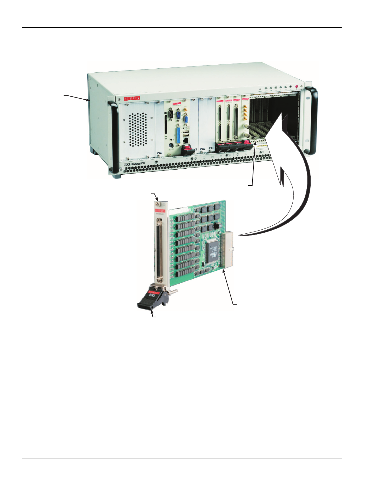
To insert the module into a PXI chassis, use the following procedure as a guide:
1. Turn off the system.
2. Align the module's edge with the card guide in the PXI chassis.
3. Slide the module into the chassis until resistance is felt from the PXI connector.
4. Push the ejector upwards and fully insert the module into the chassis. Once inserted, a
"click" can be heard from the ejector latch.
5. Tighten the screw on the front panel.
6. Turn on the system.
To remove a module from a PXI chassis, use the following procedure as a guide:
1. Turn off the system.
2. Loosen the screw on the front panel.
3. Push the ejector downwards and carefully remove the module from the chassis.
KPXI-IDIO-900-01 Rev. A / January 2007 Return to Section Topics 2-3
Page 24
Section 2: Installation KPXI Digital Isolated Card User’s Manual
Figure 2-1
Typical PXI module installation
Typical PXI
chassis
Card guide
Front panel
screw
Modules edge
Ejector latch
Step 4. Verify installation
When the system is turned on for the first time with a new module present (or a module in a new
slot), Windows Add New Hardware Wizard attempts to locate the correct driver. If it cannot find
the correct driver, even after you have loaded the driver above in Step 1, then force the Add New
Hardware Wizard to look in Windows system32 directory. The driver files should be in this
location. If they are not, shutdown the system, remove the module, and restart the installation
process.
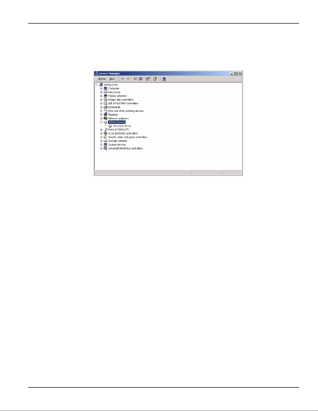
When the Add New Hardware Wizard finishes, the window will verify whether or not installation
was successful. To confirm if the module is installed correctly at a later time, use Windows Device
Manager. In the Device Manager under KIDAQ Boards, look for a device name matching the
model number of the newly installed board (see
installation is complete. If the board appears with a exclamation point or warning in Device
Manager, the installation was unsuccessful. If unsuccessful, use Device Manager to update the
2-4 Return to Section Topics KPXI-IDIO-900-01 Rev. A / January 2007
Figure 2-2 for an example). If it is found,
Page 25
KPXI Digital Isolated Card User’s Manual Section 2: Installation
driver or un-install the module, power down the system, remove the module, and attempt
installation again from Step 1.
Figure 2-2
Device manager (successful installation)
KPXI-IDIO-900-01 Rev. A / January 2007 Return to Section Topics 2-5
Page 26

Section 2: Installation KPXI Digital Isolated Card User’s Manual
This page left blank intentionally.
2-6 Return to Section Topics KPXI-IDIO-900-01 Rev. A / January 2007
Page 27

In this section:
Top ic Pa ge
Isolated digital input channels......................................................... 3-2
KPXI-DIO-16-16 isolated digital output circuits.............................. 3-2
Isolated digital output channels ...................................................... 3-3
Connector pin assignment for KPXI-DIO-16-16.............................. 3-4
Termination board connection......................................................... 3-4
Connector pin assignment for KPXI-DIO-32-32.............................. 3-5
Connector pin assignment of KPXI-DIO-64-0................................. 3-6
Section 3
Operation and connection
Connector pin assignment of KPXI-DIO-0-64................................. 3-7
Page 28
Section 3: Operation and connection KPXI Digital Isolated Card User’s Manual
(
)
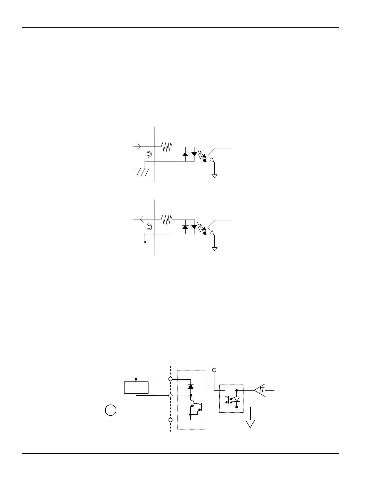
Isolated digital input channels
The isolated digital input has an open collector transistor structure. The input voltage range is 0V
to 24V (0V to 50V for Model KPXI-DIO-64-0) and the input resistance is 2.4KΩ (4.7KΩ for
Model KPXI-DIO-64-0). The connection between external signals and the Model KPXI-DIO-32-32 /
KPXI-DIO-64-0 is shown in
Figure 3-1. Please note that the input common junction could be
common ground or common power, they are dependent on the user’s environment. Therefore, the
digital input could be either a current source or a current sink.
Figure 3-1
Isolated isolated input connections
Isolated Input
Signal (source)
Current Flow
COM m
GND
Isolated Input
Signal (sink)
Current Flow
COM m
(+VDD)
2.4K Ohm
2.4K Ohm
KPXI-DIO-16-16 isolated digital output circuits
The connection of isolated digital output is shown as following diagram. Model KPXI-DIO-16-16 is
equipped with internal DC-DC converter.
On Model KPXI-DIO-16-16, the VDD pin is used as “fly-wheel” diode, which can protect the driver
if the loading is inductance loading such as relay, motor or solenoid.
You can use the following wiring diagram. The VDD must connect to the external power to form a
fly-wheel current loop.
Figure 3-2
Isolated digital output circuits wiring diagram
V
DD
Load
IDO
n
+
+
DC (5-35V)
DC (5-35V)
3-2 Return to Section Topics KPXI-IDIO-900-01 Rev. A / January 2007
EOGND
Darlington
Sink Driver
V5V
PC 817
Page 29
KPXI Digital Isolated Card User’s Manual Section 3: Operation and connection
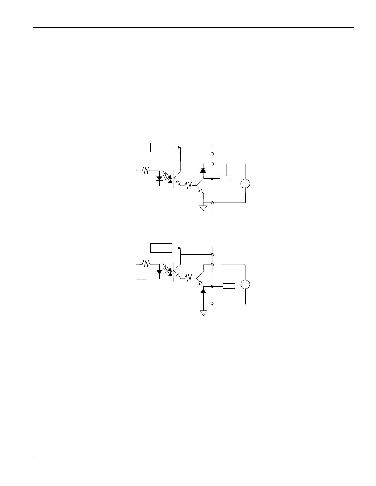
Isolated digital output channels
The common ground connection of isolated digital output is shown in Figure 3-3, while common
power connection of isolated digital output as Figure 3-4. When the isolated digital output goes
“ON”, the sink current will be conducted through the transistors. When the isolated digital output
goes “OFF”, no current is conducted flow through the transistors. Please note that when the load is
of an “inductance nature” such as a relay, coil or motor, the VDD pin must be connected to an
external power source. The extra connection is utilized for the ‘fly-wheel diode’ to form a currentrelease closed loop, so that the transistors are protected from any high reverse voltage which can
be generated by the inductance load when the output is switched from “ON” to “OFF”.
Figure 3-3
Common Ground Connection
DC-DC
Convertor
V5V
VDD n
Figure 3-4
Common Power Connection
DC-DC
Convertor
IGND
IGND
Load
V5V
VDD n
Load
+
-
5~35V
+
-
5~35V
V
V
DD
KPXI-IDIO-900-01 Rev. A / January 2007 Return to Section Topics 3-3
Page 30
Section 3: Operation and connection KPXI Digital Isolated Card User’s Manual
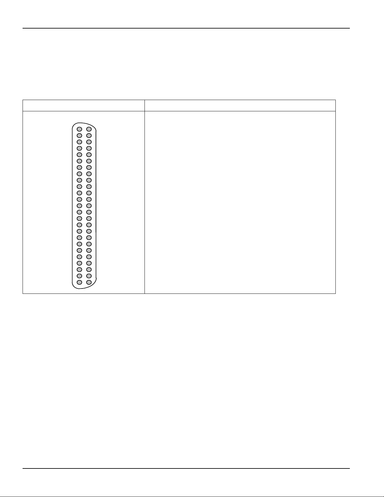
Connector pin assignment for KPXI-DIO-16-16
The pin assignment of Model KPXI-DIO-16-16’s 50 pins SCSI-II type connector CN1 is shown in
Table 3-1.
Table 3-1
KPXI-DIO-16-16: 50 pin SCSI-II type connector
Connector Legend
IDI_n: Isolated digital input channel #n.
IDO_n: Isolated digital output channel #n.
VDD
EOGND
EOGND
EOGND
ID0_6
ID0_5
ID0_4
ID0_3
ID0_2
ID0_1
ID0_0
IDI_3H IDI_7L
IDI_3L
IDI_2H
IDI_2L
IDI_1H
IDI_1L
IDI_0H
IDI_0L
IDI_11
IDI_10
IDI_9
IDI_8
(1)
(2)
(3)
(4)
(5)
(6)
(7)
(8)
(9)
(10)
(11)
(12)
(13)
(14)
(15)
(16)
(17)
(18)
(19)
(20)
(21)
(22)
(23)
(24)
(25)
(26)
(27)
(28)
(29)
(30)
(31)
(32)
(33)
(34)
(35)
(36)
(37)
(38)
(39)
(40)
(41)
(42)
(43)
(44)
(45)
(46)
(47)
(48)
(49)
(50)EICOM
VDD
EOGND
EOGND
EOGND
ID0_14ID0_7
ID0_15
ID0_12
ID0_13
ID0_10
ID0_11
ID0_8
ID0_9
IDI_7H
IDI_6L
IDI_6H
IDI_5L
IDI_5H
IDI_4L
IDI_4H
IDI_15
IDI_14
IDI_13
IDI_12
EICOM
EICOM: Common ground or common power of isolated input channels
#8~15.
IDI_nH: High input of isolated differential DI channel #n.
IDI_nL: Low input of isolated differential DI channel #n.
EOGND: Ground return path of isolated output channels.
VDD: Power input signal for fly-wheel diode of DO channels.
Termination board connection
Model KPXI-DIO-16-16 boards are equipped with a 50 pin SCSI-II type connector. The available
termination boards includes the Model KPXI-32-DIO-TB Terminal Board for KPXI-DIO-16-16
Modules. A general purposed 50-pin screw terminal with rail mount for easy installation. Model
KPXI-32-DIO-TB is shipped with a 50-pin cable. Order a Model KPXI-32-DIO-CAB cable to
connect the terminal block to the module.
3-4 Return to Section Topics KPXI-IDIO-900-01 Rev. A / January 2007
Page 31

KPXI Digital Isolated Card User’s Manual Section 3: Operation and connection
Connector pin assignment for KPXI-DIO-32-32
The pin assignment of the 100-pin SCSI-II connector for the KPXI-DIO-32-32 is shown in Ta b l e 3 - 2 .
Table 3-2
Pin Assignment of KPXI-DIO-32-32 CN1 Connector
(1) IDI_0 (26) IDO_0 (51) IDI_8 (76) IDO_8
(2) IDI_1 (27) IDO_1 (52) IDI_9 (77) IDO_9
(3) IDI_2 (28) IDO_2 (53) IDI_10 (78) IDO_10
(1)
(2)
(3)
(48)
(49)
(50)
(51)
(52)
(53)
(4) IDI_3 (29) IDO_3 (54) IDI_11 (79) IDO_11
(5) IDI_4 (30) IDO_4 (55) IDI_12 (80) IDO_12
(6) IDI_5 (31) IDO_5 (56) IDI_13 (81) IDO_13
(7) IDI_6 (32) IDO_6 (57) IDI_14 (82) IDO_14
(8) IDI_7 (33) IDO_7 (58) IDI_15 (83) IDO_15
(9) COM1 (34) VDD1 (59) COM2 (84) VDD2
(10) COM1 (35) IGND (60) COM2 (85) IGND
(11) COM1 (36) IGND (61) COM2 (86) IGND
(12) COM1 (37) IGND (62) COM2 (87) IGND
(13) IDI_16 (38) IDO_16 (63) IDI_24 (88) IDO_24
(14) IDI_17 (39) IDO_17 (64) IDI_25 (89) IDO_25
(15) IDI_18 (40) IDO_18 (65) IDI_26 (90) IDO_26
(16) IDI_19 (41) IDO_19 (66) IDI_27 (91) IDO_27
(17) IDI_20 (42) IDO_20 (67) IDI_28 (92) IDO_28
(18) IDI_21 (43) IDO_21 (68) IDI_29 (93) IDO_29
(19) IDI_22 (44) IDO_22 (69) IDI_30 (94) IDO_30
(20) IDI_23 (45) IDO_23 (70) IDI_31 (95) IDO_31
(98)
(21) COM3 (46) VDD3 (71) COM4 (96) VDD4
(99)
(100)
(22) COM3 (47) IGND (72) COM4 (97) IGND
(23) COM3 (48) IGND (73) COM4 (98) IGND
(24) COM3 (49) IGND (74) COM4 (99) IGND
(25) NC (50) V5V (75) NC (100) V5V
Legend:
IDI_n: Isolated digital input channel n
IDO_n: Isolated digital output channel n
VDDm: Common pin for output channel group m (VDD1 is common pin for isolated output
channel 0~7, VDD2 is common pin for isolated output channel 8~15, and so on).
IGND: Ground return path for isolated output channels
COMm: Common junction for isolated input channel group m (COM1 is common junction for
input channel 0~7, COM2 is common junction for input channel 8~15, and so on).
V5V: Onboard un-regulated 5V power supply output
KPXI-IDIO-900-01 Rev. A / January 2007 Return to Section Topics 3-5
Page 32

Section 3: Operation and connection KPXI Digital Isolated Card User’s Manual
Connector pin assignment of KPXI-DIO-64-0
The pin assignment of the 100-pin SCSI-II connector for the KPXI-DIO-64-0 is shown in Table 3-3.
Table 3-3
Pin Assignment of KPXI-DIO-64-0 CN1 Connector
(1) IDI_0 (26) IDI_32 (51) IDI_8 (76) IDI_40
(2) IDI_1 (27) IDI_33 (52) IDI_9 (77) IDI_41
(3) IDI_2 (28) IDI_34 (53) IDI_10 (78) IDI_42
(4) IDI_3 (29) IDI_35 (54) IDI_11 (79) IDI_43
(5) IDI_4 (30) IDI_36 (55) IDI_12 (80) IDI_44
(1)
(2)
(3)
(48)
(49)
(50)
(6) IDI_5 (31) IDI_37 (56) IDI_13 (81) IDI_45
(51)
(52)
(7) IDI_6 (32) IDI_38 (57) IDI_14 (82) IDI_46
(53)
(8) IDI_7 (33) IDI_39 (58) IDI_15 (83) IDI_47
(9) COM1 (34) COM5 (59) COM2 (84) COM6
(10) COM1 (35) COM5 (60) COM2 (85) COM6
(11) COM1 (36) COM5 (61) COM2 (86) COM6
(12) COM1 (37) COM5 (62) COM2 (87) COM6
(13) IDI_16 (38) IDI_48 (63) IDI_24 (88) IDI_56
(14) IDI_17 (39) IDI_49 (64) IDI_25 (89) IDI_57
(15) IDI_18 (40) IDI_50 (65) IDI_26 (90) IDI_58
(16) IDI_19 (41) IDI_51 (66) IDI_27 (91) IDI_59
(17) IDI_20 (42) IDI_52 (67) IDI_28 (92) IDI_60
(18) IDI_21 (43) IDI_53 (68) IDI_29 (93) IDI_61
(19) IDI_22 (44) IDI_54 (69) IDI_30 (94) IDI_62
(98)
(99)
(20) IDI_23 (45) IDI_55 (70) IDI_31 (95) IDI_63
(100)
(21) COM3 (46) COM7 (71) COM4 (96) COM8
(22) COM3 (47) COM7 (72) COM4 (97) COM8
(23) COM3 (48) COM7 (73) COM4 (98) COM8
(24) COM3 (49) COM7 (74) COM4 (99) COM8
(25) NC (50) NC (75) NC (100) NC
Legend:
IDI_n: Isolated digital input channel n.
COMm: Common junction for isolated input channel group m, (COM1 is common junction for
input channel 0~7, COM2 is common junction for input channel 8~15, COM3 is
common junction of input channel 16~23, and so on.)
3-6 Return to Section Topics KPXI-IDIO-900-01 Rev. A / January 2007
Page 33

KPXI Digital Isolated Card User’s Manual Section 3: Operation and connection
Connector pin assignment of KPXI-DIO-0-64
The pin assignment of the 100-pin SCSI-II connector for the KPXI-DIO-0-64 is shown in Table 3-4.
Table 3-4
Pin Assignment of KPXI-DIO-0-64 CN1 Connector
(1) IDO_0 (26) IDO_32 (51) IDO_8 (76) IDO_40
(2) IDO_1 (27) IDO_33 (52) IDO_9 (77) IDO_41
(3) IDO_2 (28) IDO_34 (53) IDO_10 (78) IDO_42
(1)
(2)
(3)
(48)
(49)
(50)
(4) IDO_3 (29) IDO_35 (54) IDO_11 (79) IDO_43
(51)
(5) IDO_4 (30) IDO_36 (55) IDO_12 (80) IDO_44
(52)
(53)
(6) IDO_5 (31) IDO_37 (56) IDO_13 (81) IDO_45
(7) IDO_6 (32) IDO_38 (57) IDO_14 (82) IDO_46
(8) IDO_7 (33) IDO_39 (58) IDO_15 (83) IDO_47
(9) VDD1 (34) VDD5 (59) VDD2 (84) VDD6
(10) IGND (35) IGND (60) IGND (85) IGND
(11) IGND (36) IGND (61) IGND (86) IGND
(12) IGND (37) IGND (62) IGND (87) IGND
(13) IDO_16 (38) IDO_48 (63) IDO_24 (88) IDO_56
(14) IDO_17 (39) IDO_49 (64) IDO_25 (89) IDO_57
(15) IDO_18 (40) IDO_50 (65) IDO_26 (90) IDO_58
(16) IDO_19 (41) IDO_51 (66) IDO_27 (91) IDO_59
(17) IDO_20 (42) IDO_52 (67) IDO_28 (92) IDO_60
(18) IDO_21 (43) IDO_53 (68) IDO_29 (93) IDO_61
(19) IDO_22 (44) IDO_54 (69) IDO_30 (94) IDO_62
(20) IDO_23 (45) IDO_55 (70) IDO_31 (95) IDO_63
(98)
(21) VDD3 (46) VDD7 (71) VDD4 (96) VDD8
(99)
(100)
(22) IGND (47) IGND (72) IGND (97) IGND
(23) IGND (48) IGND (73) IGND (98) IGND
(24) IGND (49) IGND (74) IGND (99) IGND
(25) NC (50) V5V (75) NC (100) V5V
Legend:
IDO_n: Isolated digital output channel n.
VDDm: Common pin for isolated output channel group m, (VDD1 is the common pin for isolated
output channel 0~7, VDD2 is for channel 8~15, VDD3 is for channel 16~23, VDD4 is for
channel 24~31, VDD5 is for channel 32~39, VDD6 is for channel 40~47, VDD7 is for
channel 48~55, and VDD8 is for channel 56~63).
IGND: Ground return path for isolated output channels.
V5V: Onboard un-regulated 5V power supply output
KPXI-IDIO-900-01 Rev. A / January 2007 Return to Section Topics 3-7
Page 34

Section 3: Operation and connection KPXI Digital Isolated Card User’s Manual
This page left blank intentionally.
3-8 Return to Section Topics KPXI-IDIO-900-01 Rev. A / January 2007
Page 35

In this section:
Top ic Pa ge
Introduction ....................................................................................... 4-2
PCI PnP registers.............................................................................. 4-2
I/O address map ................................................................................ 4-2
Digital input register ......................................................................... 4-3
Digital output register....................................................................... 4-4
Section 4
Registers
Page 36

Section 4: Registers KPXI Digital Isolated Card User’s Manual
Introduction
This section describes the details of the registers and its structure. This information is important
for programmers who want to control the hardware with low-level programming.
In addition, the low level programming syntax is introduced. This information can help beginners
to operate the module in the shortest possible time.
NOTE Direct register access can be difficult to program. All users are encouraged to use the
KDIO-DRVR driver interface instead of direct access to the registers. This section is
included only as a reference for customers who absolutely require the efficiency of
register access.
PCI PnP registers
This PCI card functions as a 32-bit PCI target device to any master on the PCI bus. There are
three types of registers: PCI Configuration Registers (PCR), Local Configuration Registers (LCR)
and registers.
The PCR, which is PCI-bus specifications compliant, is initialized and controlled by the plug & play
(PnP) PCI BIOS. Users may obtain more information on the PCI BIOS specification to better
understand the operation of the PCR. Please contact PCISIG to acquire the specifications of the
PCI interface.
The PCI bus controller PCI-9050 is provided by PLX technology Inc. (www.plxtech.com). For
more information about the LCR, please visit PLX technology’s web site to download relative
information. It is not necessary for users to fully understand the details of the LCR if the software
library provided is used. The PCI PnP BIOS assigns the base address of the LCR. The assigned
address is located at an offset of 14h from the PCR.
The KPXI-DIO-16-16/32-32/64-0/0-64 registers are discussed in the next section. The base
address, which is also assigned by the PCI PnP BIOS, is located at an offset of 18h from the PCR.
Therefore, users can read the address 18h from the PCR to obtain its base address by using the
BIOS function call. Do not attempt to modify the base address and interrupt that have been
assigned by the PCI PnP BIOS, it may cause resource conflicts with your system.
I/O address map
Registers are 32 bits long. Access these registers using 32-bit I/O instructions. The following table
shows the registers address map, including descriptions and their offset addresses relative to the
base address.
Table 4-1
I/O Address Map of KPXI-DIO-16-16/32-32/64-0/0-64
Model Address Write Read
KPXI-DIO-16-16
Base (0 – 1) Isolated DO Isolated DI
Base + 0x00 Isolated DO Isolated DI
KPXI-DIO-32-32
KPXI-DIO-64-0
4-2 Return to Section Topics KPXI-IDIO-900-01 Rev. A / January 2007
Base + 0x40 Clear IRQ --
Base + 0x00 -- Isolated DI
Base + 0x04 -- Isolated DI
Base + 0x08 Clear IRQ --
Page 37

KPXI Digital Isolated Card User’s Manual Section 4: Registers
Table 4-1
I/O Address Map of KPXI-DIO-16-16/32-32/64-0/0-64
KPXI-DIO-0-64
NOTE 1. I/O port is 32 bits width
2. 8-bit or 16-bit I/O access is not allowed.
Digital input register
There are 16/32 isolated digital input channels on the KPXI-DIO-16-16/32-32, respectively. On the
KPXI-DIO-64-0, there are 64 isolated digital input channels. Each bit of based address
corresponds to a signal on the digital input channel.
Address: BASE + 0 ~ BASE + 3 for KPXI-DIO-16-16 and KPXI-DIO-32-32
BASE + 0 ~ BASE + 7 for KPXI-DIO-64-0
Attribute: read only
Table 4-2
KPXI-DIO-16-16/KPXI-DIO-32-32 Data format
7 6 5 4 3 2 1 0
Base + 0 IDI_7 IDI_6 IDI_5 IDI_4 IDI_3 IDI_2 IDI_1 IDI_0
Base + 1 IDI_15 IDI_14 IDI_13 IDI_12 IDI_11 IDI_10 IDI_9 IDI_8
Base + 2 IDI_23 IDI_22 IDI_21 IDI_20 IDI_19 IDI_18 IDI_17 IDI_16
Base + 3 IDI_31 IDI_30 IDI_29 IDI_28 IDI_27 IDI_26 IDI_25 IDI_24
Base + 0x00 Isolated DO -Base + 0x04 Isolated DO --
Table 4-3
IDIN: KPXI-DIO-64-0 Data format
7 6 5 4 3 2 1 0
Base + 0 IDI_7 IDI_6 IDI_5 IDI_4 IDI_3 IDI_2 IDI_1 IDI_0
Base + 1 IDI_15 IDI_14 IDI_13 IDI_12 IDI_11 IDI_10 IDI_9 IDI_8
Base + 2 IDI_23 IDI_22 IDI_21 IDI_20 IDI_19 IDI_18 IDI_17 IDI_16
Base + 3 IDI_31 IDI_30 IDI_29 IDI_28 IDI_27 IDI_26 IDI_25 IDI_24
Base + 4 IDI_39 IDI_38 IDI_37 IDI_36 IDI_35 IDI_34 IDI_33 IDI_32
Base + 5 IDI_47 IDI_46 IDI_45 IDI_44 IDI_43 IDI_42 IDI_41 IDI_40
Base + 6 IDI_55 IDI_54 IDI_53 IDI_52 IDI_51 IDI_50 IDI_49 IDI_48
Base + 7 IDI_63 IDI_62 IDI_61 IDI_60 IDI_59 IDI_58 IDI_57 IDI_56
KPXI-IDIO-900-01 Rev. A / January 2007 Return to Section Topics 4-3
Page 38

Section 4: Registers KPXI Digital Isolated Card User’s Manual
Digital output register
There are 16/32 isolated digital input channels on the KPXI-DIO-16-16/32-32, respectively. On the
KPXI-DIO-0-64, there are 64 isolated digital output channels. Each bit of based address
corresponds to a signal on the digital output channel.
Address: BASE + 0 ~ BASE + 3 for KPXI-DIO-16-16 and KPXI-DIO-32-32
BASE + 0 ~ BASE + 7 for KPXI-DIO-0-64
Attribute: write only
Table 4-4
IDO_N: KPXI-DIO-16-16/KPXI-DIO-32-32 Data format
7 6 5 4 3 2 1 0
Base + 0 IDO_7 IDO_6 IDO_5 IDO_4 IDO_3 IDO_2 IDO_1 IDO_0
Base + 1 IDO_15 IDO_14 IDO_13 IDO_12 IDO_11 IDO_10 IDO_9 IDO_8
Base + 2 IDO_23 IDO_22 IDO_21 IDO_20 IDO_19 IDO_18 IDO_17 IDO_16
Base + 3 IDO_31 IDO_30 IDO_29 IDO_28 IDO_27 IDO_26 IDO_25 IDO_24
Table 4-5
IDO_N: KPXI-DIO-0-64 Data format
7 6 5 4 3 2 1 0
Base + 0 IDO_7 IDO_6 IDO_5 IDO_4 IDO_3 IDO_2 IDO_1 IDO_0
Base + 1 IDO_15 IDO_14 IDO_13 IDO_12 IDO_11 IDO_10 IDO_9 IDO_8
Base + 2 IDO_23 IDO_22 IDO_21 IDO_20 IDO_19 IDO_18 IDO_17 IDO_16
Base + 3 IDO_31 IDO_30 IDO_29 IDO_28 IDO_27 IDO_26 IDO_25 IDO_24
Base + 4 IDO_39 IDO_38 IDO_37 IDO_36 IDO_35 IDO_34 IDO_33 IDO_32
Base + 5 IDO_47 IDO_46 IDO_45 IDO_44 IDO_43 IDO_42 IDO_41 IDO_40
Base + 6 IDO_55 IDO_54 IDO_53 IDO_52 IDO_51 IDO_50 IDO_49 IDO_48
Base + 7 IDO_63 IDO_62 IDO_61 IDO_60 IDO_59 IDO_58 IDO_57 IDO_56
4-4 Return to Section Topics KPXI-IDIO-900-01 Rev. A / January 2007
Page 39

In this appendix:
Top ic Page
Introduction to KDIO-DRVR ............................................................ A-2
About the KDIO-DRVR software.......................................................A-2
KDIO-DRVR hardware support.........................................................A-2
KDIO-DRVR language support......................................................... A-2
KDIO-DRVR overview ....................................................................... A-3
General configuration function group ...............................................A-3
Actual sampling rate function group .................................................A-4
Analog output function group............................................................ A-4
Digital input function group ...............................................................A-4
Digital output function group............................................................. A-6
Timer/counter function group............................................................ A-7
DIO function group ........................................................................... A-8
Appendix A
KDIO-DRVR User’s Guide
Creating a KDIO-DRVR application............................................... A-9
Contiguous memory allocation in driver for continuous operation .... A-9
Fundamentals of building Windows XP/2000 Application......A-9
Microsoft
Using Microsoft Visual Basic.NET .................................................. A-11
Microsoft Visual C/C++................................................................... A-11
®
Visual Basic (Version 6.0) ...............................................A-9
KDIO-DRVR application hints....................................................... A-11
Digital input programming hints ......................................................A-12
Digital output programming hints.................................................... A-17
DAQ event message programming hints........................................ A-21
Interrupt event message programming hints ..................................A-22
Continuous data transfer in KDIO-DRVR ..................................A-23
Continuous data transfer mechanism.............................................A-23
Double-buffered / multiple-buffered DI operation............................ A-23
KDIO-DRVR utilities for Win32 .....................................................A-25
KDIO-DRVR configuration utility (configdrv)................................... A-25
KDIO-DRVR data file converter utility (KIDAQCvt)......................... A-26
Page 40

Appendix A: KDIO-DRVR User’s Guide KPXI Digital Isolated Card User’s Manual
Introduction to KDIO-DRVR
About the KDIO-DRVR software
KDIO-DRVR is a software development kit for Keithley Instruments PXI digital I/O modules. It
contains a high performance data acquisition driver for developing custom applications under
Windows XP or Windows 2000
The memory and data buffer management capabilities free developers from dealing with complex
low-level command issues. That is, KDIO-DRVR is constructed to provide a simple programming
interface in communication with the Keithley PXI digital I/O modules. The easy-to-use functions
provided by KDIO-DRVR allow a programmer to use the features of the module in a high level
way.
1
environments.
Using KDIO-DRVR also allows you to take advantage of the power and features of Microsoft
Win32s
extended memory. Also, using KDIO-DRVR under in the Microsoft Visual Basic
makes it easy to create custom user interfaces and graphics.
In addition to the software drivers, some sample programs are provided for your reference to
demonstrate use of the driver and decrease development time.
®
for your data acquisition applications, including running multiple applications and using
KDIO-DRVR hardware support
Keithley will periodically upgrade KDIO-DRVR for new Keithley PXI digital I/O modules. Please
refer to Release Notes for the modules that the current KDIO-DRVR actually supports. The
following modules are currently supported by the KDIO-DRVR driver:
• KPXI-DIO-16-16: 16-channel isolated digital I/O module
• KPXI-DIO-48: 48-bit digital I/O module
• KPXI-RDI-8-16: 8 relay output and 16 isolated input module
• KPXI-DIO-32-80M: 80 Mbytes/second Ultra-high speed 32 channels digital I/O module with
bus mastering DMA transfer supporting scatter gather technology
• KPXI-DIO-32-32: 32 isolated channels DI & 32 isolated channels DO module
• KPXI-DIO-64-0: 64 isolated channels DI module
• KPXI-DIO-0-64: 64 isolated channels DO module
KDIO-DRVR language support
®
environment
KDIO-DRVR is a DLL (Dynamic-Link Library) version for using under Windows XP/2000. It can
work with any Windows programming language that allows calls to a DLL, such as Microsoft
Visual C/Visual C++
above), etc.
1. Windows XP, Windows 2000, Microsoft Win32s, Visual C/Visual C++, and Visual Basic are trademarks of
Microsoft Corporation.
the
2. Borland is a trademark of the Borland Software Corporation.
A-2 Return to Section Topics KPXI-IDIO-900-01 Rev. A / January 2007
®
(5.0 or above), Borland® C++ (5.0 or above)2, or Visual Basic® (4.0 or
®
Page 41

KPXI Digital Isolated Card User’s Manual Appendix A: KDIO-DRVR User’s Guide
KDIO-DRVR overview
NOTE Based on the configuration of an individual module, some of the function groups will not
apply to a particular module.
This section describes the classes of functions in KDIO-DRVR and briefly describes each function.
KDIO-DRVR functions are grouped to the following classes:
• General Configuration Function Group
• Actual Sampling Rate Function Group
• Analog Output Function Group
• Digital Input Function Group
– Digital Input Configuration functions
– One-Shot Digital Input functions
– Continuous Digital Input functions
– Asynchronous Digital Input Monitoring functions
• Digital Output Function Group
– Digital Output Configuration functions
– One-Shot Digital Output functions
– Continuous Digital Output functions
– Asynchronous Digital Output Monitoring functions
• Timer/Counter Function Group
• DIO Function Group
– Digital Input/Output Configuration function
– Dual-Interrupt System Setting function
General configuration function group
Use these functions to initialize and configure the data acquisition card.
KDIO_Register_Card
Initializes the hardware and software states of a KIDAQ PCI-bus data acquisition card.
Register_Card must be called before any other KDIO-DRVR library functions can be called for that
card.
KDIO_Release_Card
Tells KDIO-DRVR library that this registered card is not used currently and can be released. This
would make room for a new card to be registered.
KDIO_GetCardType
Gets the card type of the device with a specified card index.
KDIO_GetCardIndexFromID
Gets the card type and the sequence number of the device with a specified card id.
KDIO_GetBaseAddr
Gets the I/O base addresses of the device with a specified card index.
KPXI-IDIO-900-01 Rev. A / January 2007 Return to Section Topics A-3
Page 42

Appendix A: KDIO-DRVR User’s Guide KPXI Digital Isolated Card User’s Manual
KDIO_GetLCRAddr
Gets the LCR base address (defined by the PCI controller on board) of the device with a specified
card index.
Actual sampling rate function group
KDIO_GetActualRate
Returns the actual sampling rate the device will perform for the defined sampling rate value.
Analog output function group
One-shot analog output functions
KDIO_AO_WriteChannel
Writes a binary value to the specified analog output channel.
KDIO_AO_VWriteChannel
Accepts a voltage value, scales it to the proper binary value and writes a binary value to the
specified analog output channel.
KDIO_AO_VoltScale
Scales a voltage to a binary value.
Digital input function group
Digital input configuration functions
KDIO_DI_DIO32M80_Config
Informs KDIO-DRVR library of the trigger source and trigger properties selected for the digital input
operation of the KPXI-DIO-32-80M. You must call this function before calling the function to
perform continuous digital input operation of the KPXI-DIO-32-80M. This function is used only with
Model KPXI-DIO-32-80M.
KDIO_DI_InitialMemoryAllocated
Gets the actual size of digital input DMA memory that is available in the device driver.
One-Shot Digital Input Functions
KDIO_DI_ReadLine
Reads the digital logic state of the specified digital line in the specified port.
KDIO_DI_ReadPort
Reads digital data from the specified digital input port.
A-4 Return to Section Topics KPXI-IDIO-900-01 Rev. A / January 2007
Page 43

KPXI Digital Isolated Card User’s Manual Appendix A: KDIO-DRVR User’s Guide
Continuous digital input functions
KDIO_DI_ContReadPort
Performs continuous digital input on the specified digital input port at a rate as close as possible to
the rate you specified.
KDIO_DI_ContReadPortToFile
Performs continuous digital input on the specified digital input port at a rate as close as possible to
the rate you specified and saves the acquired data in a disk file.
KDIO_DI_ContStatus
Checks the current status of the continuous digital input operation.
KDIO_DI_EventCallBack
Controls and notifies the user’s application when a specified DAQ event occurs. The notification is
performed through a user-specified callback function.
KDIO_DI_ContMultiBufferSetup
Set up the buffer for multi-buffered continuous digital input.
KDIO_DI_ContMultiBufferStart
Starts the multi-buffered continuous digital input on the specified digital input port at a rate as close
as possible to the rate you specified.
Asynchronous digital input monitoring functions
KDIO_DI_AsyncCheck
Checks the current status of the asynchronous digital input operation.
KDIO_DI_AsyncClear
Stops the asynchronous digital input operation.
KDIO_DI_AsyncDblBufferTransfer
Copies half of the data of circular buffer to user buffer. You can execute this function repeatedly to
return sequential half buffers of the data.
KDIO_DI_AsyncMultiBufferNextReady
Checks whether the next buffer of data in circular buffer is ready for transfer during an
asynchronous multi-buffered digital input operation.
KDIO_DI_AsyncDblBufferOverrun
Checks or clears overrun status of the double-buffered digital input operation.
KPXI-IDIO-900-01 Rev. A / January 2007 Return to Section Topics A-5
Page 44

Appendix A: KDIO-DRVR User’s Guide KPXI Digital Isolated Card User’s Manual
Digital output function group
Digital output configuration functions
KDIO_DO_DIO32M80_Config
Informs KDIO-DRVR library of the trigger source and trigger properties selected for the digital
output operation of the KPXI-DIO-32-80M. You must call this function before calling the function to
perform continuous digital output operation of the KPXI-DIO-32-80M. This function is used only
with Model KPXI-DIO-32-80M.
KDIO_DO_InitialMemoryAllocated
Gets the actual size of digital output DMA memory that is available in the device driver.
One-Shot Digital Output Functions
KDIO_DO_WriteLine
Sets the specified digital output line in the specified digital output port to the specified state. This
function is only available for those cards that support digital output read-back functionality.
KDIO_DO_WritePort
Writes digital data to the specified digital output port.
KDIO_DO_ReadLine
Reads the specified digital output line in the specified digital output port.
KDIO_DO_ReadPort
Reads digital data from the specified digital output port.
Continuous digital output functions
KDIO_DO_ContWritePort
Performs continuous digital output on the specified digital output port at a rate as close as possible
to the rate you specified.
KDIO_DO_ContStatus
Checks the current status of the continuous digital output operation.
KDIO_DO_EventCallBack
Controls and notifies the user’s application when a specified DAQ event occurs. The notification is
performed through a user-specified callback function.
KDIO_DO_PGStart
Performs pattern generation operation.
KDIO_DO_PGStop
Stops pattern generation operation.
A-6 Return to Section Topics KPXI-IDIO-900-01 Rev. A / January 2007
Page 45

KPXI Digital Isolated Card User’s Manual Appendix A: KDIO-DRVR User’s Guide
KDIO_DO_ContMultiBufferSetup
Set up the buffer for multi-buffered continuous digital output.
KDIO_DO_ContMultiBufferStart
Starts the multi-buffered continuous digital output on the specified digital output port at a rate as
close as possible to the rate you specified.
Asynchronous digital output monitoring functions
KDIO_DO_AsyncCheck
Checks the current status of the asynchronous digital output operation.
KDIO_DO_AsyncClear
Stops the asynchronous digital output operation.
KDIO_DO_AsyncMultiBufferNextReady
Checks whether the next buffer is ready for new data during an asynchronous multi-buffered digital
output operation.
Timer/counter function group
Timer/counter functions
KDIO_CTR_Setup
Configures the selected counter to operate in the specified mode.
KDIO_CTR_Read
Reads the current contents of the selected counter.
KDIO_CTR_Clear
Sets the output of the selected counter to the specified state.
KDIO_CTR_Update
Writes a new initial count to the selected counter.
KDIO_CTR_CT12_ClkSrc_Config
Sets the counter clock source.
KDIO_CTR_CT12_CK1_Config
Sets the source of CK1.
KDIO_CTR_CT12_Debounce_Config
Sets the debounce clock.
KPXI-IDIO-900-01 Rev. A / January 2007 Return to Section Topics A-7
Page 46

Appendix A: KDIO-DRVR User’s Guide KPXI Digital Isolated Card User’s Manual
DIO function group
Digital input/output configuration functions
KDIO_DIO_PortConfig
This function is only used by the Digital I/O cards whose I/O port can be set as input port or output
port. This function informs KDIO-DRVR library of the port direction selected for the digital input/
output operation. You must call this function before calling functions to perform digital input/output
operation.
Dual-interrupt system setting functions
KDIO_SetDualInterrupt
Controls two interrupt sources of Dual Interrupt system.
KDIO_INT_EventMessage
Controls and notifies the user’s application when an interrupt event occurs. The notification is
performed through a user-specified callback function or the Windows PostMessage API.
KDIO_INT1_EventMessage
Controls the interrupt sources of INT1 of Dual Interrupt system and notifies the user’s application
when an interrupt event occurs. The notification is performed through a user-specified callback
function or the Windows PostMessage API.
KDIO_INT2_EventMessage
Controls the interrupt sources of INT2 of Dual Interrupt system and notifies the user’s application
when an interrupt event occurs. The notification is performed through a user-specified callback
function or the Windows PostMessage API.
Local interrupt setting functions
KDIO_DIO32M80_SetInterrupt
Controls the interrupt sources (AUXDI and Timer2) of local Interrupt system of KPXI-DIO-32-80M.
This function is used only with Model KPXI-DIO-32-80M.
KDIO_AUXDI_EventMessage
Controls AUXDI Interrupt and notifies the user’s application when an interrupt event occurs. The
notification is performed through a user-specified callback function or the Windows PostMessage
API.
KDIO_T2_EventMessage
Controls Timer2 Interrupt and notifies the user’s application when an interrupt event occurs. The
notification is performed through a user-specified callback function or the Windows PostMessage
API.
A-8 Return to Section Topics KPXI-IDIO-900-01 Rev. A / January 2007
Page 47

KPXI Digital Isolated Card User’s Manual Appendix A: KDIO-DRVR User’s Guide
Creating a KDIO-DRVR application
Contiguous memory allocation in driver for continuous operation
The continuous data transfer functions in KDIO-DRVR input or output blocks of data to or from a
Keithley Instruments PXI digital I/O device. To avoid the data transfer performance reduction
caused by memory fragmentation, KDIO-DRVR allocates physically contiguous buffers in device
driver when the system boots.
KDIO-DRVR provides a utility, configdrv to set/modify the sizes of contiguous memory allocated
in driver for continuous analog input, analog output, digital input, digital output. Device driver will
try to allocate these sizes of memory. The size of initially allocated memory is the maximum
memory size that continuous data transfer can be performed. Please refer to the section,
KDIO-DRVR configuration utility (configdrv), for the description of this utility.
KDIO-DRVR inputs or outputs blocks of data stored in the driver buffer to or from a Keithley PXI
device. For input operations, the specified count of data are transferred to the driver buffer and
KDIO-DRVR copies the data from the driver buffer (kernel level) to a user buffer (user level). For
output operations, KDIO-DRVR copies the data from a user buffer (driver level) to the driver buffer
(kernel level) and transfers outgoing data from the driver buffer to the Keithley PXI device.
However, if only polling I/O is performed, the initially allocated memory is not needed and you can
use the utility,
KDIO-DRVR configuration utility (configdrv) to set the buffer size to be 0.
Fundamentals of building Windows XP/2000 Application
The following paragraphs outline how to create Windows1 XP/2000 KDAQ-DRVR projects using
Microsoft Visual Basic® (Version 6.0), Microsoft Visual Basic.NET, and Microsoft Visual C/C++®.
Microsoft® Visual Basic (Version 6.0)
To create a Windows XP/2000® Keithley KDIO-DRVR application using the API and Microsoft
Visual Basic, follow these steps:
Step 1: Enter Visual Basic and open or create a project to use KDIO-DRVR
To create a new project, select New Project from the File menu.
To use an existing project:
1. Open the file by selecting Open Project from the File menu. The Open Project dialog box
appears (Figure A-1).
1. Windows XP, Windows 2000, Microsoft Visual Basic.NET, Microsoft Visual C/Visual C++, and Microsoft
Visual Basic
KPXI-IDIO-900-01 Rev. A / January 2007 Return to Section Topics A-9
are trademarks of the Microsoft Corporation.
Page 48

Appendix A: KDIO-DRVR User’s Guide KPXI Digital Isolated Card User’s Manual
Figure A-1
Open Project dialog box
2. Load the project by finding and double-clicking the project file name in the applicable
directory.
Step 2: Include function declarations and constants file (kdiodrvr.bas)
If it is not already included in the project, add the kdiodrvr.bas file as a module to your project. All
function declarations and constants are contained in this file. These function declarations and
constants are used to develop data acquisition applications.
Step 3: Design the application interface
Add elements, such as a command button, list box, or text box, etc., on the Visual Basic form used
to design the interface. These elements are standard controls from the Visual Basic Toolbox. To
place a needed control on the form:
1. Select the needed control from the Toolbox.
2. Draw the control on the form. Alternatively, to place the default-sized control on the form,
click the form. Use the Select Objects tool to reposition or resize controls.
Step 4: Set control properties
Set control properties from the properties list. To view the properties list, select the desired control
and do one of the following:
• Press F4
• Select the Properties command in the View menu
or
• Click the Properties button on the Toolbar.
Step 5: Write the event codes
The event codes define the action desired when an event occurs. To write the event codes:
1. Double-click the control or form needing event code (the code module will appear).
2. Add new code as needed. All functions that are declared in kdiodrvr.bas can be called to
perform data acquisition operations (refer to tables contained later in this manual).
A-10 Return to Section Topics KPXI-IDIO-900-01 Rev. A / January 2007
Page 49

KPXI Digital Isolated Card User’s Manual Appendix A: KDIO-DRVR User’s Guide
Step 6: Run your application
To run the application, either:
• Press F5
•Select Start from the Run menu
or
• Click the Start icon on the Toolbar
Using Microsoft Visual Basic.NET
To create a data acquisition application using KDAQ-DRVR and Visual Basic.NET, use the
procedure for
KDIODRVR.VB (instead of the file named kdiodrvr.bas).
Microsoft® Visual Basic (Version 6.0) as an outline, but in step 2, use the file named
Microsoft Visual C/C++
To create a Windows XP/2000 KDAQ-DRVR library application using the KDAQ-DRVR function
library and Microsoft Visual C/C++, follow these steps:
Step 1: Enter Visual C/C++ and open or create a project that will use the
KDIO-DRVR
NOTE The project can be a new or existing one.
Step 2: Include function declarations and constants file (kdiodrvr.h)
Include kdiodrvr.h in the C/C++ source files that call KDIO-DRVR functions by adding the
following statement in the source file:
#include "kdiodrvr.h"
NOTE: KDIO-DRVR function declarations and constants are contained in kdiodrvr.h. Use the
functions and constants to develop data-acquisition applications.
Step 3: Build your application
1. Set suitable compile and link options.
2. Select Build from the Build menu (Visual C/C++ 4.0 and higher).
3. Remember to link the Keithley Command Compatible library: KDIO-DRVR.LIB
KDIO-DRVR application hints
This section provides the programming schemes showing the function flow of that KDIO-DRVR
performs analog I/O and digital I/O.
The figure below shows the basic building blocks of a KDIO-DRVR application. However, except
using KDIO_Register_Card at the beginning and KDIO_Release_Card at the end, depending on
the specific devices and applications you have, the KDIO-DRVR functions comprising each
building block vary.
KPXI-IDIO-900-01 Rev. A / January 2007 Return to Section Topics A-11
Page 50

Appendix A: KDIO-DRVR User’s Guide KPXI Digital Isolated Card User’s Manual
Figure A-2
Basic KDIO-DRVR building blocks
The programming schemes for digital input/output are described individually in the following
sections.
Digital input programming hints
KDIO-DRVR provides two kinds of digital input operation ⎯ non-buffered single-point digital input
operation and buffered continuous digital input operation.
The non-buffered single-point DI uses software polling method to read data from the device.
The programming scheme for this kind of DI operation is described in
programming.
The buffered continuous DI uses DMA transfer method to transfer data from device to user’s
buffer. The maximum number of count in one transfer depends on the size of initially allocated
memory for digital input in the driver. We recommend the applications use the
KDIO_DI_InitialMemoryAllocated function to get the size of initially allocated memory before
performing continuous DI operation.
The buffered continuous analog input includes synchronous continuous DI, non-double-buffered
asynchronous continuous DI and double-buffered asynchronous continuous DI. They are
described in
asynchronous continuous digital input programming, and Multiple-buffered asynchronous
continuous digital input programming. About the special consideration and performance issues for
the buffered continuous digital input, refer to the section titled Continuous data transfer in KDIO-
DRVR for details.
Synchronous continuous digital input programming, Non-multiple-buffered
One-shot digital input
A-12 Return to Section Topics KPXI-IDIO-900-01 Rev. A / January 2007
Page 51

KPXI Digital Isolated Card User’s Manual Appendix A: KDIO-DRVR User’s Guide
One-shot digital input programming
This section describes the function flow typical of non-buffered single-point digital input readings.
While performing one-shot DI operation, the devices whose I/O port can be set as input or out put
port need to include port configuration function at the beginning of your application.
NOTE The following example uses a KPXI-DIO-48. Other DIO modules are similar (exceptions
are noted).
Figure A-3
One-shot digital input programming
Example Code Fragment
card = KDIO_Register_Card(KPXI_DIO_48, card_number);
//port configured
KDIO_PortConfig(card ,Channel_P1A, INPUT_PORT);
KDIO_PortConfig(card, Channel_P1B, INPUT_PORT);
KDIO_PortConfig(card, Channel_P1CL, INPUT_PORT);
KDIO_PortConfig(card, Channel_P1CH, INPUT_PORT);
//DI operation
KDIO_DI_ReadPort(card, Channel_P1A, &inputA);
…
KDIO_Release_Card(card);
KPXI-IDIO-900-01 Rev. A / January 2007 Return to Section Topics A-13
Page 52

Appendix A: KDIO-DRVR User’s Guide KPXI Digital Isolated Card User’s Manual
Synchronous continuous digital input programming
This section describes the function flow typical of synchronous digital input operation. While
performing continuous DI operation, the DI configuration function has to be called at the beginning
of your application. In addition, for synchronous DI, the SyncMode argument in continuous DI
functions has to be set as SYNCH_OP.
NOTE The following example uses a KPXI-DIO-32-80M. Other DIO modules are similar with the
exception being that some modules do not require the _Config function call (specifically,
if the module’s ports are dedicated as inputs or outputs only).
Figure A-4
Synchronous continuous digital input programming
KDIO_DI_xxxx_Config
xxxx means the card type,
(
e.g.
KDIO_DI_DIO32M80_Config)
With SyncMode=SYNCH_OP
KDIO_DI_ContReadPort /
KDIO_DI_ContReadPortToFile
Example Code Fragment
card = KDIO_Register_Card(KPXI_DIO_32_80M, card_number);
…
KDIO_DI_DIO32M80_Config (card, 16, TRIG_CLK_10MHZ, DIO32M80_WAIT_NO,
DIO32M80_TERM_ON, 0, 1, 1);
KDIO_DI_ContReadPort(card, 0, pMem, data_size, (F64)sample_rate, SYNCH_OP)
…
KDIO_Release_Card(card);
Non-multiple-buffered asynchronous continuous digital input programming
This section describes the function flow typical of non-double-buffered asynchronous digital input
operation. While performing continuous DI operation, the DI configuration function has to be called
at the beginning of your application. In addition, for asynchronous DI operation, the SyncMode
argument in continuous DI functions has to be set as ASYNCH_OP.
A-14 Return to Section Topics KPXI-IDIO-900-01 Rev. A / January 2007
Page 53

KPXI Digital Isolated Card User’s Manual Appendix A: KDIO-DRVR User’s Guide
NOTE The following example uses a KPXI-DIO-32-80M. Other DIO modules are similar with the
exception being that some modules do not require the _Config function call (specifically,
if the module’s ports are dedicated as inputs or outputs only).
Figure A-5
Non-multiple-buffered asynchronous continuous digital input
KDIO_DI_xxxx_Config
xxxx means the card type,
(
e.g.
KDIO_DI_DIO32M80_Config)
With SyncMode=ASYNCH_OP
KDIO_DI_ContReadPort /
KDIO_DI_ContReadPortToFile
KDIO_DI_AsyncCheck
No
Operation complete?
Yes
KDIO_DI_AsyncClear
Example Code Fragment
card = KDIO_Register_Card(KPXI_DIO_32_80M, card_number);
…
KDIO_DI_DIO32M80_Config(card, 16, TRIG_CLK_10MHZ, DIO32M80_WAIT_NO,
DIO32M80_TERM_ON, 0, 1, 1);
KDIO_DI_ContReadPort(card, 0, pMem, data_size, (F64)sample_rate, ASYNCH_OP)
do {
KDIO_DI_AsyncCheck(card, &bStopped, &count);
} while (!bStopped);
KDIO_DI_AsyncClear(card, &count);
…
KDIO_Release_Card(card);
Multiple-buffered asynchronous continuous digital input programming
This section describes the function flow typical of multi-buffered asynchronous digital input
operation. While performing continuous DI operation, the DI configuration function has to be called
at the beginning of your application. For asynchronous DI, the SyncMode argument in continuous
DI functions has to be set as ASYNCH_OP.
NOTE The following example uses a KPXI-DIO-32-80M. Other DIO modules are similar with the
exception being that some modules do not require the _Config function call (specifically,
if the module’s ports are dedicated as inputs or outputs only).
KPXI-IDIO-900-01 Rev. A / January 2007 Return to Section Topics A-15
Page 54

Appendix A: KDIO-DRVR User’s Guide KPXI Digital Isolated Card User’s Manual
Figure A-6
Multiple-buffered asynchronous continuous digital input
KDIO_DI_xxxx_Config
xxxx means the card type,
(
e.g. KDIO_DI_DIO32M80_Config
KDIO_DI_ContMultiBufferSetup
KDIO_DI_ContMultiBufferStart
KDIO_DI_AsyncMultiBufferNextReady
)
No
Next half buffer
ready?
Yes
Handling the ready data
No
Want to stop
the operation?
Yes
KDIO_DI_AsyncClear
Example Code Fragment
card = KDIO_Register_Card(KPXI_DIO_32_80M, card_number);
…
KDIO_DI_DIO32M80_Config(card, 16, TRIG_CLK_10MHZ, DIO32M80_WAIT_NO,
DIO32M80_TERM_ON, 0, 0, 0);
//setting the DMA buffers repeatedly
KDIO_DI_ContMultiBufferSetup (card, in_buf, data_size, &BufferId);
KDIO_DI_ContMultiBufferSetup (card, in_buf, data_size, &BufferId);
…
// start multi-buffered DI
KDIO_DI_ContMultiBufferStart (card, 0, 1);
do {
do {
KDIO_DI_AsyncMultiBufferNextReady(card, &HalfReady, &viewidx);
} while (!HalfReady);
//Handling the ready data
} while (!clear_op);
KDIO_DI_AsyncClear(card, &count);
…
KDIO_Release_Card(card);
A-16 Return to Section Topics KPXI-IDIO-900-01 Rev. A / January 2007
Page 55

KPXI Digital Isolated Card User’s Manual Appendix A: KDIO-DRVR User’s Guide
Digital output programming hints
KDIO-DRVR provides three kinds of digital output operation ⎯ non-buffered single-point digital
output operation, buffered continuous digital output operation and pattern generation.
The non-buffered single-point DO uses software polling method to write data to the device. The
programming scheme for this kind of DO operation is described in
programming scheme.
The buffered continuous DO uses DMA transfer method to transfer data from user’s buffer to
device. The maximum number of count in one transfer depends on the size of initially allocated
memory for digital output in the driver. We recommend the applications use
KDIO_DO_InitialMemoryAllocated function to get the size of initially allocated memory before
start performing continuous DO operation.
The buffered continuous digital output includes synchronous continuous DO and asynchronous
continuous DO. They are described in
Synchronous continuous digital output programming and
Asynchronous continuous digital output programming individually. About the special consideration
and performance issues for the buffered continuous digital output, refer to the section titled
Continuous data transfer in KDIO-DRVR for details.
The Pattern Generation DO outputs digital data patterns repeatedly at a predetermined rate. The
programming scheme for this kind of DO operation is described in
programming.
One-shot digital output
Pattern generation digital output
One-shot digital output programming scheme
This section describes the function flow typical of non-buffered single-point digital output
operation. While performing one-shot DO operation, the cards whose I/O port can be set as input
or output port need to include port configuration function at the beginning of your application.
NOTE The following example uses a KPXI-DIO-48. Other DIO modules are similar with the
exception being that some modules do not require the _Config function call (specifically,
if the module’s ports are dedicated as inputs or outputs only).
Example Code Fragment
card = KDIO_Register_Card(KPXI_DIO_48, card_number);
//port configured
KDIO_PortConfig(card ,Channel_P1A, OUTPUT_PORT);
KDIO_PortConfig(card, Channel_P1B, OUTPUT_PORT);
KDIO_PortConfig(card, Channel_P1CL, OUTPUT_PORT);
KDIO_PortConfig(card, Channel_P1CH, OUTPUT_PORT);
//DO operation
KDIO_DO_WritePort(card, Channel_P1A, outA_value);
…
KDIO_Release_Card(card);
Synchronous continuous digital output programming
This section describes the function flow typical of synchronous digital output operation. While
performing continuous DO operation, the DO configuration function has to be called at the
beginning of your application. In addition, for synchronous DO operation, the SyncMode argument
in continuous DO functions for synchronous mode has to be set as SYNCH_OP.
NOTE The following example uses a KPXI-DIO-32-80M. Other DIO modules are similar with the
exception being that some modules do not require the _Config function call (specifically,
if the module’s ports are dedicated as inputs or outputs only).
KPXI-IDIO-900-01 Rev. A / January 2007 Return to Section Topics A-17
Page 56

Appendix A: KDIO-DRVR User’s Guide KPXI Digital Isolated Card User’s Manual
Figure A-7
Synchronous continuous digital output programming
KDIO_DO_xxxx_Config
xxxx means the card type,
(
e.g. DO_DIO32M80_Config
With SyncMode=SYNCH_OP
KDIO_DO_ContWritePort
)
Example Code Fragment
card = KDIO_Register_Card(KPXI_DIO_32_80M, card_number);
…
KDIO_DO_DIO32M80_Config (card, 16, TRIG_INT_PACER, DIO32M80_WAIT_NO,
DIO32M80_TERM_ON, 0, 0x40004000);
KDIO_DO_ContWritePort(card, 0, DoBuf, count, 1, (F64)sample_rate, SYNCH_OP);
…
KDIO_Release_Card(card);
Asynchronous continuous digital output programming
This section describes the function flow typical of asynchronous digital output operation. While
performing continuous DO operation, the DO configuration function has to be called at the
beginning of your application. In addition, for asynchronous DO operation, the SyncMode
argument in continuous DO functions for asynchronous mode has to be set as ASYNCH_OP.
NOTE The following example uses a KPXI-DIO-32-80M. Other DIO modules are similar with the
exception being that some modules do not require the _Config function call (specifically,
if the module’s ports are dedicated as inputs or outputs only).
Figure A-8
Asynchronous continuous digital output programming
KDIO_DO_xxxx_Config
xxxx means the card type,
(
e.g. KDIO_DO_DIO32M80_Config
KDIO_DO_ContWritePort
KDIO_DO_AsyncCheck
No
Operation complete?
With SyncMode=ASYNCH_OP
)
Yes
KDIO_DO_AsyncClear
A-18 Return to Section Topics KPXI-IDIO-900-01 Rev. A / January 2007
Page 57

KPXI Digital Isolated Card User’s Manual Appendix A: KDIO-DRVR User’s Guide
Example Code Fragment
card = KDIO_Register_Card(KPXI_DIO_32_80M, card_number);
…
KDIO_DO_DIO32M80_Config (card, 16, TRIG_INT_PACER, DIO32M80_WAIT_NO,
DIO32M80_TERM_ON, 0, 0x40004000);
KDIO_DO_ContWritePort(card, 0, DoBuf, count, 1, (F64)sample_rate, ASYNCH_OP);
do {
KDIO_DO_AsyncCheck(card, &bStopped, &count);
} while (!bStopped);
KDIO_DO_AsyncClear(card, &count);
…
KDIO_Release_Card(card);
Pattern generation digital output programming
This section describes the function flow typical of pattern generation for digital output. While
performing pattern generation of DO, the DO configuration function has to be called at the
beginning of your application.
NOTE The following example uses a KPXI-DIO-32-80M. Other DIO modules are similar with the
exception being that some modules do not require the _Config function call (specifically,
if the module’s ports are dedicated as inputs or outputs only).
Figure A-9
Pattern generation digital output programming
Example Code Fragment
card=KDIO_Register_Card(KPXI_DIO_32_80M, card_number);
…
KDIO_DO_DIO32M80_Config (card, 16, TRIG_INT_PACER, DIO32M80_WAIT_NO,
DIO32M80_TERM_ON, 0, 0x40004000);
//start pattern generation
KDIO_DO_PGStart (card, out_buf, 10000, 5000000);
…
//stop pattern generation
KDIO_DO_PGStop (card);
KDIO_Release_Card(card);
KPXI-IDIO-900-01 Rev. A / January 2007 Return to Section Topics A-19
Page 58

Appendix A: KDIO-DRVR User’s Guide KPXI Digital Isolated Card User’s Manual
Multiple-buffered asynchronous continuous digital output programming
This section describes the function flow typical of multi-buffered asynchronous digital output
operation. While performing continuous DO operation, the DO configuration function has to be
called at the beginning of your application. For asynchronous DO, the SyncMode argument in
continuous DO functions has to be set as ASYNCH_OP.
NOTE The following example uses a KPXI-DIO-32-80M. Other DIO modules are similar with the
exception being that some modules do not require the _Config function call (specifically,
if the module’s ports are dedicated as inputs or outputs only).
Figure A-10
Multiple-buffered asynchronous continuous digital output
KDIO_DO_xxxx_Config
xxxx means the card type,
(
e.g. KDIO_DO_DIO32M80_Config
KDIO_DO_ContMultiBufferSetup
KDIO_DO_ContMultiBufferStart
)
KDIO_DO_AsyncMultiBufferNextReady
No
Next half buffer
ready?
Yes
Copy prepared data to the ready
buffer
No
Want to stop
the operation?
Yes
KDIO_DO_AsyncClear
Example Code Fragment
card = KDIO_Register_Card(KPXI_DIO_32_80M, card_number);
…
KDIO_DO_DIO32M80_Config (card, 16, /*TRIG_INT_PACER*/TRIG_CLK_10MHZ,
DIO32M80_WAIT_NO, DIO32M80_TERM_ON, 0, 0x00040004)
//setting the DMA buffers repeatedly
KDIO_DO_ContMultiBufferSetup (card, out_buf, data_size, &BufferId);
KDIO_DO_ContMultiBufferSetup (card, out_buf, data_size, &BufferId);
…
// start multi-buffered DO
A-20 Return to Section Topics KPXI-IDIO-900-01 Rev. A / January 2007
Page 59

KPXI Digital Isolated Card User’s Manual Appendix A: KDIO-DRVR User’s Guide
KDIO_DO_ContMultiBufferStart (card, 0, 1);
do {
do {
KDIO_DI_AsyncMultiBufferNextReady(card, &HalfReady, &viewidx);
} while (!HalfReady);
// Copy prepared data to the ready buffer
} while (!clear_op);
KDIO_DO_AsyncClear(card, &count);
…
KDIO_Release_Card(card);
DAQ event message programming hints
DAQ Event Message functions are an efficient way to monitor your background data acquisition
processes, without dedicating your foreground process for status checking. There are two kinds of
events, which are DI/DO operation completeness notification event and buffer ready notification
event.
To receive notification from the KDIO-DRVR data acquisition process in case of special events,
you can call KDIO_DI_EventCallBack, or KDIO_DO_EventCallBack to specify an event in
which you are interested.
Event notification is done through user-defined callbacks. When a user-specified DAQ event
occurs, KDIO-DRVR calls the user-defined callback. After receiving the message, the user’s
application can carry out the appropriate task.
The event message mechanism is easy and safe in Windows systems; however, the time delay
between the event and notification is highly variable and depends largely on how loaded your
system is. In addition, if a callback function is called, succeeding events will not be handled until
your callback has returned. If the time interval between events is smaller than the time taken for
callback function processing, the succeeding events will not be handled. Therefore this
mechanism is not suitable for the frequent events occurrence condition.
NOTE The following example uses a KPXI-DIO-32-80M. Other DIO modules are similar with the
exception being that some modules do not require the _Config function call (specifically,
if the module’s ports are dedicated as inputs or outputs only).
Example Code Fragment
card = KDIO_Register_Card(KPXI_DIO_32_80M, card_number);
KDIO_DI_DIO32M80_Config(card, 16, TRIG_CLK_10MHZ, DIO32M80_WAIT_NO,
DIO32M80_TERM_ON, 0, 0, 0);
// Enable half buffer ready event notification
KDIO_DI_EventCallBack (card, 1, DBEvent, (U32) DI_DBCallBack );
//Enable DI completeness event notification
KDIO_DI_EventCallBack (card, 1, DIEnd, (U32) DI_CallBack );
KDIO_DI_ContMultiBufferStart (card, 0, 1);
....
KDIO_Release_Card(card);
//Half buffer ready call back function
void DI_DBCallBack()
{
//half buffer is ready
KDIO_DI_AsyncDblBufferTransfer(card, &HalfReady, &viewidx);
….
KPXI-IDIO-900-01 Rev. A / January 2007 Return to Section Topics A-21
Page 60

Appendix A: KDIO-DRVR User’s Guide KPXI Digital Isolated Card User’s Manual
}
//DI completeness call back function
void DI_CallBack ()
{
//DI is completed ]
KDIO_DO_AsyncClear (card, &count);
….
}
Interrupt event message programming hints
KDIO-DRVR provides two methods to perform interrupt occurrence notification for Keithley PXI
DIO cards that have dual interrupt system.
The Event Message method handles event notification through user-defined callbacks and/or the
Windows Message queue (for VB5, through user-defined callbacks only). When a user-specified
interrupt event occurs, KDIO-DRVR calls the user-defined callback (if defined) and/or puts a
message into the Windows Message queue, if you specified a window handle. After receiving the
message, the user’s application can carry out the appropriate task.
The event message mechanism is easy and safe in Windows systems; however, the time delay
between the event and notification is highly variable and depends largely on how loaded your
system is. In addition, if a callback function is called, succeeding events will not be handled until
your callback has returned. If the time interval between interrupt events is smaller than the time
taken for callback function processing, the succeeding interrupt events will not be handled.
Therefore this mechanism is not suitable for the frequent interrupt occurrence condition.
The Event Status checking and waiting method handles interrupt event status checking
through Win32 wait functions, such as WaitForSingleObject or WaitForMultipleObjects. This
method is useful for the situation that the interrupt event occurs very often, and the applications
written in the language that doesn’t support function pointers (e.g. VB4).
1. Through user-defined callbacks and the Windows Message queue
Example Code Fragment
card = KDIO_Register_Card(KPXI-DIO-16-16, card_number);
//INT1 event notification is through window message
KDIO_INT1_EventMessage (card, INT1_EXT_SIGNAL, hWnd, WM_INT, NULL);
//INT2 event notification is through a callback function
KDIO_INT2_EventMessage (card, INT2_EXT_SIGNAL, hWnd, NULL, (void *) cbfn);
….
//window message handling function
long PASCAL MainWndProc(hWnd, message, wParam, lParam)
{
switch(message) {
….
case WM_INT: //interrupt event occurring message
….
break;
….
case WM_DESTROY:
//Disable interrupts
KDIO_INT1_EventMessage (card, INT1_DISABLE, hMainWnd, NULL, NULL);
KDIO_INT2_EventMessage (card, INT2_DISABLE, hMainWnd, NULL, NULL);
//Release card
if (card >= 0) KDIO_Release_Card(card);
A-22 Return to Section Topics KPXI-IDIO-900-01 Rev. A / January 2007
Page 61

KPXI Digital Isolated Card User’s Manual Appendix A: KDIO-DRVR User’s Guide
PostQuitMessage(0);
break;
….
}
}
….
//call back function
LRESULT CALLBACK cbfn()
{
….
}
2. Through a Win32 wait function
Example Code Fragment
card = KDIO_Register_Card(KPXI-DIO-16-16, card_number);
KDIO_SetDualInterrupt(card, INT1_EXT_SIGNAL, INT2_EXT_SIGNAL, hEvent);
….
//wait for INT1 event
if (WaitForSingleObject(hEvent[0], INFINITE) == WAIT_OBJECT_0) {
ResetEvent(hEvent[0]);
……
}
…..
//wait for INT2 event
if (WaitForSingleObject(hEvent[1], INFINITE) == WAIT_OBJECT_0) {
ResetEvent(hEvent[1]);
……
}
…..
if (card >= 0) KDIO_Release_Card(card);
Continuous data transfer in KDIO-DRVR
The continuous data transfer functions in KDIO-DRVR input or output blocks of data to or from a
plug-in Keithley PXI digital I/O device. For input operations, KDIO-DRVR must transfer the
incoming data to a buffer in the computer memory. For output operations, KDIO-DRVR must
transfer outgoing data from a buffer in the computer memory to the Keithley PXI digital I/O device.
This section describes the mechanism and techniques that KDIO-DRVR uses for continuous data
transfer and the considerations for selecting the continuous data transfer mode (sync. or async.,
double buffered or not, triggered or non-triggered mode).
Continuous data transfer mechanism
KDIO-DRVR uses two mechanisms to perform the continuous data transfer. The first one, interrupt
transfer, transfers data through the interrupt mechanism. The second one is to use the DMA
controller chip to perform a hardware transfer of the data. Whether KDIO-DRVR uses interrupt or
DMA depends on the device. If the device support both of these two mechanisms, KDIO-DRVR
decides on the data transfer method that typically takes maximum advantage of available
resources.
Double-buffered / multiple-buffered DI operation
KDIO-DRVR uses double-buffering / multiple buffering techniques in its driver software for
continuous input of large amounts of data.
KPXI-IDIO-900-01 Rev. A / January 2007 Return to Section Topics A-23
Page 62

Appendix A: KDIO-DRVR User’s Guide KPXI Digital Isolated Card User’s Manual
Double/multiple buffer mode principle
The data buffer for double (multiple)-buffered continuous input operation is a circular buffer
logically. It is logically divided into two equal halves. The double-buffered input begins when device
starts writing data into the first half of the circular buffer (
to the second half of the circular buffer, you can copy the data from the first half into the transfer
buffer (user buffer) (
Figure A-11b). You now can process the data in the transfer buffer according
to application needs. After the board has filled the second half of the circular buffer, the board
returns to the first half buffer and overwrites the old data. You now can copy the second half of the
circular buffer to the transfer buffer (
Figure A-11c). The data in the transfer buffer is again available
for process. The process can be repeated endlessly to provide a continuous stream of data to your
application (
Figure A-11d).
Figure A-11
Double/multiple buffer mode principle
Figure A-11a). After device begins writing
a
Incoming DMA
input data
c
> >
Circular Buffer
Transfer Buffer
Empty Buffer Untransferred Data Transferred Data
b
> > >
d
> > >> >
The KDIO-DRVR double buffer mode functions were designed according to the principle described
above. If you use KDIO_DI_AsyncDblBufferMode to enable double buffer mode, the following
continuous AI/DI function will perform double-buffered continuous DI. You can call
KDIO_DI_AsyncDblBufferHalfReady to check if data in the circular buffer is half full and
ready for copying to the transfer buffer. Then you can call
KDIO_DI_AsyncDblBufferTransfer to copy data from the ready half buffer to the transfer
buffer.
Single-buffered versus double (multiple)-buffered data transfer
Single-buffered data transfer is the most common method for continuous data transfer. In singlebuffered input operations, a fixed number of samples are acquired at a specified rate and
transferred into user’s buffer. After the user’s buffer stores the data, the application can analyze,
display, or store the data to the hard disk for later processing. Single-buffered operations are
relatively simple to implement and can usually take advantage of the full hardware speed of the
device. However, the major disadvantage of single-buffered operation is that the maximum amount
of data that can be input at any one time is limited to the amount of initially allocated memory
allocated in driver and the amount of free memory available in the computer.
In double (multiple)-buffered operations, as mentioned above, the data buffer is configured as a
circular buffer. Therefore, unlike single-buffered operations, double-buffered operations reuse the
same buffer and are able to input or output an infinite number of data points without requiring an
infinite amount of memory. However, there exits the undesired result of data overwritten for
A-24 Return to Section Topics KPXI-IDIO-900-01 Rev. A / January 2007
Page 63

KPXI Digital Isolated Card User’s Manual Appendix A: KDIO-DRVR User’s Guide
double-buffered data transfer. The device might overwrite data before KDIO-DRVR has copied it to
the transfer buffer. Another data overwritten problem occurs when an input device overwrites data
that KDIO-DRVR is simultaneously copying to the transfer buffer. Therefore, the data must be
processed by the application at least as fast as the rate at which the device is reading data. For
most of the applications, this requirement depends on the speed and efficiency of the computer
system and programming language.
Hence, double buffering might not be practical for high-speed input applications.
KDIO-DRVR utilities for Win32
This section introduces the tools that accompanied with the KDIO-DRVR package.
KDIO-DRVR configuration utility (configdrv)
configdrv is used for the users to set/modify the allocated buffer sizes of DI and DO. The default
location of this utility is <InstallDir>\Util directory.
[configdrv in Windows XP/2000]
This utility is used to set/modify the allocated buffer sizes of DI and DO. The allocated buffer sizes
of DI, DO represent the sizes of contiguous Initially Allocated memory for continuous analog input,
analog output, digital input, digital output respectively. Its unit is page KB, i.e. 1024 bytes. Device
driver will try to allocate these sizes of memory at system startup time. The size of initially
allocated memory is the maximum memory size that DMA or Interrupt transfer can be performed. It
will induce an unexpected result in that DMA or Interrupt transfer performed exceeds the initially
allocated size.
The “Driver Configuration” window is shown as below.
Figure A-12
Driver configuration window
KPXI-DIO-32-80M
AI:
AO:
DI:
DO:
0
0
32768
1024
perform
Using configdrv to change the buffer allocated settings of one of the KDIO-DRVR drivers,
select the driver from the Card Type combo box.
KPXI-IDIO-900-01 Rev. A / January 2007 Return to Section Topics A-25
Page 64

Appendix A: KDIO-DRVR User’s Guide KPXI Digital Isolated Card User’s Manual
Inside the allocated buffer size fields of AI, AO, DI and DO are the originally set values. Type the
value in the box corresponding to AI, AO, DI, or DO according to the requirement of your
applications, and then click “Apply” button.
KDIO-DRVR data file converter utility (KIDAQCvt)
The data files, generated by the KDAQ-DRVR functions performing continuous data acquisition
followed by storing the data to disk, is written in binary format. Since a binary file can’t be read by
the normal text editor and can’t be used to analyze the accessed data by Excel, KDAQ-DRVR
provides a convenient tool KIDAQCvt to convert the binary file to the file format read easily. The
default location of this utility is <InstallDir>\Util directory. The KIDAQCvt main window is as the
following figure:
Figure A-13
DAQ File Conversion Utility
The KIDAQCvt main window includes two frames. The upper frame, Input File frame is used for
the source data file and the lower frame is used for the destination file.
To load the source binary data file, type the binary data file name in File Path field or click
Browser button to select the source file from Input File frame, and then click Load button. As the
file is loaded, the information related to the data file, e.g. data type, data width, AD Range,
…etc., are shown in the corresponding fields in “Input File” frame, and the default converted data
file path and format are also listed as the figure below.
A-26 Return to Section Topics KPXI-IDIO-900-01 Rev. A / January 2007
Page 65

KPXI Digital Isolated Card User’s Manual Appendix A: KDIO-DRVR User’s Guide
Figure A-14
Loading source binary data file
KIDAQ Driver Conversion Utility
F:\Keithley\KDIO_DRVR\SAMPLES\KPXI_DIO_32_80M\CAIR
KPXI-DIO-32-80M
F:\Keithley\KDIO_DRVR\SAMPLES\KPXI_DIO_32_80M\CAIR
The default destination file with a .cvt extension is located in the same directory as the source
one. To change the default setting, type the file path you wish or click the Browse button from
Output File frame to select the destination file location.
KIDAQCvt provides three types of data format conversions:
Text file with scaled data:
The data in hexadecimal format is scaled to engineering unit (voltage, amp, …etc) according to the
card type, data width and data range and then written to disk in text file format. This type is
available for the data accessed from continuous AI operation only.
Binary file with scaled data:
The data in hexadecimal is scaled to engineering unit (voltage, amp, …etc) according to the card
type, data width and data range and then written to disk in binary file format. This type is available
for the data accessed from continuous AI operation only.
Text file with binary codes:
The data in hexadecimal format or converted to a decimal value is written to disk in text file format.
If the original data includes channel information, the raw value will be handled to get the real data
value. This type is available for the data accessed form continuous AI and DI operations.
The data separator in converted text file is selectable among space, comma and Tab.
If you want to add title/head which includes the card type information at the beginning of file, check
the “Title/Head” box.
After setting the properties (File Path, Format, …etc) related to the converted file, you can push
Start Convert button from the Output File frame to perform the file conversion.
KPXI-IDIO-900-01 Rev. A / January 2007 Return to Section Topics A-27
Page 66

Appendix A: KDIO-DRVR User’s Guide KPXI Digital Isolated Card User’s Manual
This page left blank intentionally.
A-28 Return to Section Topics KPXI-IDIO-900-01 Rev. A / January 2007
Page 67

In this appendix:
Top ic Page
Function description ................................................................ B-2
Data types ............................................................................. B-2
Function reference ................................................................ B-2
Status Codes ........................................................................... B-38
Data file format........................................................................ B-40
Header ................................................................................ B-40
ChannelRange .................................................................... B-41
Data Block........................................................................... B-42
Function Support.................................................................... B-43
Appendix B
KDIO-DRVR Function Reference
Page 68

Appendix B: KDIO-DRVR Function Reference KPXI Digital Isolated Card User’s Manual
Function description
This section is provided as a function reference. It contains a detailed description of KDIO-DRVR
functions and includes information on KDIO-DRVR
reference (functions are arranged alphabetically in the reference). Syntax is provided for Microsoft
C/C++, and Borland C++, as well as Visual Basic.
Data types
Tab l e B - 1 contains data types defined in kdiodrvr.h. These data types are used by the
KDIO-DRVR library. It is recommended these data types are used in your application programs.
Tab l e B - 1 contains data type names, ranges, and the corresponding data types for C/C++ and
Visual Basic.
NOTE The data types in Tabl e B- 1 are defined in kdiodrvr.h, but are not defined in
kdiodrvr.bas (for .bas definition files, the table is provided only as a reference).
Tab l e B - 1
Suggested data types
Data types as well as a KDIO-DRVR Function
Type
Type
Name Description Range
U8 8-bit ASCII character 0 to 255 unsigned
I16 16-bit signed integer -32768 to 32767 short Integer
U16 16-bit unsigned integer 0 to 65535 unsigned
I32 32-bit signed integer -2147483648 to
U32 32-bit unsigned integer 0 to 4294967295 unsigned
F32 32-bit single-precision
floating
-point
F64 64-bit double-precision
floating
-point
Function reference
KDIO-DRVR is a software driver for Keithley Instruments PXI DIO cards. It is a high performance
data acquisition driver for developing custom applications.
Using KDIO-DRVR also lets you take advantage of the power and features of Microsoft Windows
for your data acquisition applications. These include running multiple applications and using
extended memory. Also, using KDIO-DRVR under environment makes it easy to create custom
user interfaces and graphics.
2147483647
-3.402823E38 to
3.402823E38
-1.797683134862315E308
to
1.797683134862315E309
C/C++
(for 32-bit
compiler) Visual Basic
Byte
char
Not supported by this type,
short
long Long
long
float Single
double Double
use the signed integer (I16)
instead
Not supported by this type,
use the signed long integer
(I32) instead
KDIO_CTR_Clear
Description Turns off the specified counter operation and sets the output of the selected
counter to the specified state. This function is supported by the following models:
KPXI-DIO-48
B-2 Return to Section Topics KPXI-IDIO-900-01 Rev. A / January 2007
Page 69

KPXI Digital Isolated Card User’s Manual Appendix B: KDIO-DRVR Function Reference
Syntax Microsoft C/C++ and Borland C++
I16 KDIO_CTR_Clear (U16 CardNumber, U16 Ctr, U16 State)
Visual Basic
KDIO_CTR_Clear (ByVal CardNumber As Integer,
ByVal Ctr As Integer, ByVal State As Integer) As Integer
Parameters CardNumber: The card id number.
Ctr: The counter number.
Range: 0, 1, 2 for KPXI-DIO-48
state: The logic state to which the counter is to be reset.
Range: 0 or 1.
Return Code NoError, ErrorInvalidCardNumber, ErrorCardNotRegistered,
ErrorFuncNotSupport, InvalidCounter
KDIO_CTR_Read
Description Reads the current contents of the selected counter without disturbing the counting
process. This function is supported by the following models:
KPXI-DIO-48
Syntax Microsoft C/C++ and Borland C++
I16 KDIO_CTR_Read (U16 CardNumber, U16 Ctr, U32 *Value)
Visual Basic
KDIO_CTR_Read (ByVal CardNumber As Integer, ByVal Ctr As
Integer, Value As Long) As Integer
Parameters CardNumber: The card id number.
Ctr: The counter number.
Range: 0, 1, 2 for KPXI-DIO-48
Value: Returns the current count of the specified counter.
Range: 0 through 65536 for binary mode (default).
0 through 9999 for BCD counting mode.
Return Code NoError, ErrorInvalidCardNumber, ErrorCardNotRegistered,
ErrorFuncNotSupport, InvalidCounter
KDIO_CTR_Setup
Description Configures the selected counter to operate in the specified mode. This function is
supported by the following models: KPXI-DIO-48
Syntax Microsoft C/C++ and Borland C++
I16 KDIO_CTR_Setup (U16 CardNumber, U16 Ctr, U16 Mode,
U32 Count, U16 BinBcd)
Visual Basic
KDIO_CTR_Setup (ByVal CardNumber As Integer,
ByVal Ctr As Integer, ByVal Mode As Integer,
ByVal Count As Long, ByVal BinBcd As Integer) As Integer
KPXI-IDIO-900-01 Rev. A / January 2007 Return to Section Topics B-3
Page 70

Appendix B: KDIO-DRVR Function Reference KPXI Digital Isolated Card User’s Manual
Parameters CardNumber: The card id number.
Ctr: The counter number.
Range: 0, 1, 2 for KPXI-DIO-48
Mode: The mode in which the counter is to operate. Valid values:
TOGGLE_OUTPUT
PROG_ONE_SHOT
RATE_GENERATOR
SQ_WAVE_RATE_GENERATOR
SOFT_TRIG
HARD_TRIG
TOGGLE_OUTPUT: Toggle output from low to high on terminal count. In this
mode, the output goes low after the mode set operation, and the counter begins to
count down while the gate input is high. When terminal count is reached, the
output goes high and remains high until the selected counter is set to a different
mode. The following diagram shows the TOGGLE_OUTPUT mode timing
diagram.
Figure B-1
TOGGLE_OUTPUT mode timing
Clock
WR
Gate
Output
(n = 6)
6 5 4
PROG_ONE_SHOT: Programmable one-shot. In this mode, the output goes low
on the following rising edge of the gate input and goes high on terminal count.
The following diagram shows the PROG_ONE_SHOT mode timing diagram.
Figure B-2
PROG_ONE_SHOT mode timing
Clock
Gate
Output
(n = 4)
RATE_GENERATOR: Rate generator. In this mode, the output goes low for one
period of the clock input. count indicates the period from one output pulse to the
next. The following diagram shows the RATE_GENERATOR mode timing
diagram.
A
A + B = n
4 3 2 1 0
3 2 1 0
B
B-4 Return to Section Topics KPXI-IDIO-900-01 Rev. A / January 2007
Page 71

KPXI Digital Isolated Card User’s Manual Appendix B: KDIO-DRVR Function Reference
Figure B-3
RATE_GENERATOR mode timing
Clock
Gate
Output
4 3 2 1 0 (4) 3 2 1 0 (4)
(n = 4)
SQ_WAVE_RATE_GENERATOR: Square wave rate generator. In this mode, the
output stays high for one half of the count clock pulses and stays low for the other
half. The following diagram shows the SQ_WAVE_RATE_GENERATOR mode
timing diagram.
Figure B-4
SQ_WAVE_RATE_GENERATOR mode timing
Clock
Gate
Output (n = 4)
Output (n = 5)
4 2 4 2 4 2 4 2 4 2 4 2
5 4 2 5 2 5 4 2 5 2 5 4
SOFT_TRIG: Software-triggered strobe. In this mode, the output is initially high,
and the counter begins to count down while the gate input is high. On terminal
count, the output goes low for one clock pulse, then goes high again. The
following diagram shows the SOFT_TRIG mode timing diagram.
Figure B-5
SOFT_TRIG mode timing
Clock
WR
Gate
Output
HARD_TRIG: Hardware-triggered strobe. This mode is similar to SOFT_TRIG
mode except that the gate input is used as a trigger to start counting. The
following diagram shows the HARD_TRIG mode timing diagram.
Figure B-6
HARD_TRIG mode timing
Clock
Gate
Output
n = 4
n = 4
4 3 2 1 0
4 3 2 1 0
Count: The period from one output pulse to the next.
BinBcd: Whether the counter operates as a 16-bit binary counter or as a 4-
decade binary-coded decimal (BCD) counter.
Valid value:
BIN: 16-bit binary counter.
BCD: 4-decade BCD counter.
KPXI-IDIO-900-01 Rev. A / January 2007 Return to Section Topics B-5
Page 72

Appendix B: KDIO-DRVR Function Reference KPXI Digital Isolated Card User’s Manual
Return Code NoError, ErrorInvalidCardNumber, ErrorCardNotRegistered,
ErrorFuncNotSupport, InvalidCounter
KDIO_CTR_Update
Description A new initial count is written to the selected counter without affecting the counter’s
progrmmed mode. This function is supported by the following models:
KPXI-DIO-48
Syntax Microsoft C/C++ and Borland C++
I16 KDIO_CTR_Update (U16 CardNumber, U16 Ctr, U32 Count)
Visual Basic
KDIO_CTR_Update (ByVal CardNumber As Integer,
ByVal Ctr As Integer, ByVal count As Long) As Integer
Parameters CardNumber: The card id number.
Ctr: The counter number.
Range: 0, 1, 2 for KPXI-DIO-48
count: the new count for the specified counter.
Range: 0 through 65536 for binary mode (default).
0 through 9999 for BCD counting mode.
Return Code NoError, ErrorInvalidCardNumber, ErrorCardNotRegistered,
ErrorFuncNotSupport, InvalidCounter
KDIO_DI_DIO32M80_Config
Description Informs KDIO-DRVR library of the trigger source, port width, etc. selected for
KPXI-DIO-32-80M card with card ID CardNumber. You must call this function
before calling function to perform continuous digital input operation. This function
is supported by the following models: KPXI-DIO-32-80M
Syntax Microsoft C/C++ and Borland C++
I16 KDIO_DI_DIO32M80_Config (U16 CardNumber, U16 PortWidth,
U16 TrigSource, U16 WaitStatus, U16 Terminator,
U16 I_Cntrl_Pol, BOOLEAN ClearFifo, BOOLEAN DisableDI)
Visual Basic
KDIO_DI_DIO32M80_Config (ByVal CardNumber As Integer,
ByVal PortWidth As Integer, ByVal TrigSource As Integer,
ByVal WaitStatus As Integer, ByVal Terminator As Integer,
ByVal I_Cntrl_Pol As Integer, ByVal ClearFifo As Byte,
ByVal DisableDI As Byte) As Integer
Parameters CardNumber: The card id number.
PortWidth: The width of digital input port (PORT A). The valid value is 0, 8, 16, or
32.
TrigSource: The trigger mode for continuous digital input.
Valid values:
TRIG_INT_PACER: on-board programmable pacer timer
B-6 Return to Section Topics KPXI-IDIO-900-01 Rev. A / January 2007
Page 73

KPXI Digital Isolated Card User’s Manual Appendix B: KDIO-DRVR Function Reference
TRIG_EXT_STROBE: external signal trigger
TRIG_HANDSHAKE: handshaking
TRIG_CLK_10MHz: 10MHz clock
TRIG_CLK_20MHz: 20MHz clock
WaitStatus: DI Wait Trigger Status. Valid values are:
DIO32M80_WAIT_NO: input sampling starts immediately
DIO32M80_WAIT_TRG: digital input sampling waits rising or falling
edge of I_TRG to start DI
Terminator: PortA Terminator On/Off. Valid values:
DIO32M80_TERM_ON: terminator on
DIO32M80_TERM_OFF: terminator off
I_Cntrl_Pol: The polarity configuration. This argument is an integer expression
formed from one or more of the manifest constants defined in kdiodrvr.h. There
are three groups of constants:
(1) DIREQ
DIO32M80_DIREQ_POS: DIREQ signal is rising edge active
DIO32M80_DIREQ_NEG: DIREQ signal is falling edge active
(2) DIACK
DIO32M80_DIACK_POS: DIACK signal is rising edge active
DIO32M80_DIACK_NEG: DIACK signal is falling edge active
(3) DITRIG
DIO32M80_DITRIG_POS: DITRIG signal is rising edge active
DIO32M80_DITRIG_NEG: DITRIG signal is falling edge active
ClearFifo: FALSE: retain the FIFO data
TRUE: clear FIFO data before perform digital input
DisableDI: FALSE: digital input operation still active after DMA transfer complete.
The input data still put into FIFO
TRUE: disable digital input operation immediately when
DMA transfer complete
Return Code NoError, ErrorInvalidCardNumber, ErrorCardNotRegistered,
ErrorFuncNotSupport
KDIO_DI_AsyncCheck
Description Check the current status of the asynchronous digital input operation. This function
is supported by the following models: KPXI-DIO-32-80M
Syntax Microsoft C/C++ and Borland C++
I16 KDIO_DI_AsyncCheck (U16 CardNumber, BOOLEAN *Stopped,
U32 *AccessCnt)
Visual Basic
KDIO_DI_AsyncCheck (ByVal CardNumber As Integer,
Stopped As Byte, AccessCnt As Long) As Integer
KPXI-IDIO-900-01 Rev. A / January 2007 Return to Section Topics B-7
Page 74

Appendix B: KDIO-DRVR Function Reference KPXI Digital Isolated Card User’s Manual
Parameters CardNumber: The card id of the card that performs the asynchronous operation.
Stopped: Whether the asynchronous analog input operation has completed. If
Stopped = TRUE, the digital input operation has stopped. Either the number of
digital input indicated in the call that initiated the asynchronous digital input
operation has completed or an error has occurred. If Stopped = FALSE, the
operation is not yet complete. (constants TRUE and FALSE are defined in
kdiodrvr.h)
AccessCnt: The number of digital input data that has been transferred at the time
the call to KDIO_DI_AsyncCheck(). AccessCnt is of no use (always returns 0)
in KDIO_DI_AsyncCheck() and KDIO_ DI_AsyncClear() with KPXI-DIO-32-80M
board because on-board chip (PLX9080) of KPXI-DIO-32-80M has no function or
register to get the current amount of DMA transfer.
Return Code NoError, ErrorInvalidCardNumber, ErrorCardNotRegistered,
ErrorFuncNotSupport
KDIO_DI_AsyncClear
Description Stop the asynchronous digital input operation. This function is supported by the
following models: KPXI-DIO-32-80M
Syntax Microsoft C/C++ and Borland C++
I16 KDIO_DI_AsyncClear (U16 CardNumber, U32 *AccessCnt)
Visual Basic
KDIO_DI_AsyncClear (ByVal CardNumber As Integer,
AccessCnt As Long) As Integer
Parameters CardNumber: The card id of the card that performs the asynchronous operation.
AccessCnt: The number of digital input data that has been transferred at the time
the call to KDIO_DI_AsyncClear().
If double-buffered mode is enabled, AccessCnt returns the next position after the
position the last data is stored in the circular buffer. If the AccessCnt exceeds the
half size of circular buffer, call "KIO_DI_AsyncDblBufferTransfer " twice to get the
data.
AccessCnt is of no use (always returns 0) in KDIO_DI_AsyncCheck() and
KDIO_DI_AsyncClear() with KPXI-DIO-32-80M board because on-board chip
(PLX9080) of KPXI-DIO-32-80M has no function or register to get the current
amount of DMA transfer.
Return Code NoError, ErrorInvalidCardNumber, ErrorCardNotRegistered,
ErrorFuncNotSupport
KDIO_DI_AsyncDblBufferOverrun
Description Checks or clears overrun status of the double-buffered/multi-buffered digital input
operation. This function is supported by the following models: KPXI-DIO-32-80M
Syntax Microsoft C/C++ and Borland C++
I16 KDIO_DI_AsyncDblBufferOverrun (U16 CardNumber, U16 op,
U16 *overrunFlag)
B-8 Return to Section Topics KPXI-IDIO-900-01 Rev. A / January 2007
Page 75

KPXI Digital Isolated Card User’s Manual Appendix B: KDIO-DRVR Function Reference
Visual Basic
KDIO_DI_AsyncDblBufferOverrun (ByVal CardNumber As Integer,
ByVal op As Integer, overrunFlag As Integer) As Integer
Parameters CardNumber: The card id of the card that double-buffered mode to be set.
op: check/clear overrun status/flag.
0: check the overrun status.
1: clear the overrun flag.
overrunFlag: returned overrun status
0: no overrun occurs.
1: overrun occurs.
Return Code NoError, ErrorInvalidCardNumber, ErrorCardNotRegistered,
ErrorFuncNotSupport
KDIO_DI_AsyncDblBufferTransfer
Description Depending on the continuous DI function selected, half of the data of the circular
buffer will be logged into the user buffer (if continuous DI function is:
KDIO_DI_ContReadPort) or a disk file (if continuous DI function is:
KDIO_DI_ContReadPortToFile). If the data will be saved in a file, the data is
written to disk in binary format, with the lower byte first (little endian).
You can execute this function repeatedly to return sequential half buffers of the
data.
For KPXI-DIO-32-80M, KDIO_DI_AsyncDblBufferTransfer doesn't perform
memory transfer but notifies kdiodrvr.dll the data stored in buffer have been
handled.
This function is supported by the following models: KPXI-DIO-32-80M
Syntax Microsoft C/C++ and Borland C++
I16 KDIO_DI_AsyncDblBufferTransfer (U16 CardNumber,
void *Buffer)
Visual Basic
KDIO_DI_AsyncDblBufferTransfer (ByVal CardNumber As Integer,
Buffer As Any) As Integer
Parameters CardNumber: The card id of the card that performs the asynchronous double-
buffered operation.
Buffer: The user buffer to which the data is to be copied. If the data will be
saved into a disk file, this argument is of no use.
Return Code NoError, ErrorInvalidCardNumber, ErrorCardNotRegistered,
ErrorFuncNotSupport, ErrorNotDoubleBufferMode
KDIO_DI_AsyncMultiBufferNextReady
Description Checks whether the next buffer of data in circular buffer is ready for transfer
during an asynchronous multi-buffered digital input operation. The returned
BufferId is the index of the most recently available (newest available) buffer. This
function is supported by the following models: KPXI-DIO-32-80M
KPXI-IDIO-900-01 Rev. A / January 2007 Return to Section Topics B-9
Page 76

Appendix B: KDIO-DRVR Function Reference KPXI Digital Isolated Card User’s Manual
Syntax Microsoft C/C++ and Borland C++
I16 KDIO_DI_AsyncMultiBufferNextReady (U16 CardNumber,
BOOLEAN *NextReady, U16 *BufferId)
Visual Basic
KDIO_DI_AsyncMultiBufferNextReady (
ByVal CardNumber As Integer, NextReady As Byte,
BufferId As Integer) As Integer
CardNumber: The card id of the card that performs the asynchronous multibuffered operation.
NextReady: Whether the next buffer of data is available. If NextReady = TRUE,
you can handle the data in the buffer. (constants TRUE and FALSE are defined in
kdiodrvr.h)
BufferId: Returns the index of the ready buffer.
Return Code NoError, ErrorInvalidCardNumber, ErrorCardNotRegistered,
ErrorFuncNotSupport
KDIO_DI_ContMultiBufferSetup
Description This function set up the buffer for multi-buffered digital input. The function has to
be called repeatedly to setup all of the data buffers (at most 8 buffers). This
function is supported by the following models: KPXI-DIO-32-80M
Syntax Microsoft C/C++ and Borland C++
I16 KDIO_DI_ContMultiBufferSetup (U16 CardNumber,
void *Buffer, U32 ReadCount, U16 *BufferId)
Visual Basic
KDIO_DI_ContMultiBufferSetup (ByVal CardNumber As Integer,
Buffer As Any, ByVal ReadCount As Long,
BufferId As Integer) As Integer
Parameters CardNumber: The card id number.
Buffer: The starting address of the memory to contain the input data.
ReadCount: The size (in samples) of the buffer and its value must be even.
BufferId: Returns the index of the buffer currently set up.
Return Code NoError, ErrorInvalidCardNumber, ErrorCardNotRegistered,
ErrorFuncNotSupport, ErrorTransferCountTooLarge, ErrorContIoNotAllowed
KDIO_DI_ContMultiBufferStart
Description This function starts multi-buffered continuous digital input on the specified digital
input port at a rate as close to the rate you specified. This function is supported by
the following models: KPXI-DIO-32-80M
Syntax Microsoft C/C++ and Borland C++
I16 KDIO_DI_ContMultiBufferStart (U16 CardNumber, U16 Port,
F64 SampleRate)
B-10 Return to Section Topics KPXI-IDIO-900-01 Rev. A / January 2007
Page 77

KPXI Digital Isolated Card User’s Manual Appendix B: KDIO-DRVR Function Reference
Visual Basic
KDIO_DI_ContMultiBufferStart (ByVal CardNumber As Integer,
ByVal Port As Integer, ByVal SampleRate As Double)
As Integer
Parameters CardNumber: The card id number.
Port: Digital input port number. For KPXI-DIO-32-80M, this argument must
be set to 0.
SampleRate: The sampling rate you want for digital input in hertz (samples per
second). Your maximum rate depends on the card type and your computer
system. This argument is only useful if the DI trigger mode was set as internal
programmable pacer (TRIG_INT_PACER) by calling
KDIO_DI_DIO32M80_Config().
Return Code NoError, ErrorInvalidCardNumber, ErrorCardNotRegistered,
ErrorFuncNotSupport, ErrorInvalidIoChannel, ErrorContIoNotAllowed
KDIO_DI_ContReadPort
Description This function performs continuous digital input on the specified digital input port at
a rate as close to the rate you specified. This function is supported by the
following models: KPXI-DIO-32-80M
Syntax Microsoft C/C++ and Borland C++
I16 KDIO_DI_ContReadPort (U16 CardNumber, U16 Port,
void *Buffer, U32 ReadCount, F64 SampleRate, U16 SyncMode)
Visual Basic
KDIO_DI_ContReadPort (ByVal CardNumber As Integer,
ByVal Port As Integer, Buffer As Any,
ByVal ReadCount As Long, ByVal SampleRate As Double,
ByVal SyncMode As Integer) As Integer
Parameters CardNumber: The card id number.
Port: Digital input port number. For KPXI-DIO-32-80M, this argument must be set
to 0.
Buffer: The starting address of the memory to contain the input data. This
memory must have been allocated for enough space to store input data. If doublebuffered mode is enabled, this buffer is of no use, you can ignore this argument.
ReadCount: If double-buffered mode is disabled, ReadCount is the number of
input operations to be performed. For double-buffered acquisition, ReadCount is
the size (in samples) of the circular buffer and its value must be even.
SampleRate: The sampling rate you want for digital input in hertz (samples per
second). Your maximum rate depends on the card type and your computer
system. This argument is only useful if the DI trigger mode was set as internal
programmable pacer (TRIG_INT_PACER) by calling
KDIO_DI_DIO32M80_Config(). For the other settings, you have to set this
argument as CLKSRC_EXT_SampRate.
SyncMode: Whether this operation is performed synchronously or
asynchronously.
KPXI-IDIO-900-01 Rev. A / January 2007 Return to Section Topics B-11
Page 78

Appendix B: KDIO-DRVR Function Reference KPXI Digital Isolated Card User’s Manual
Valid values:
SYNCH_OP: synchronous digital input, that is, the function does not return until
the digital input operation complete.
ASYNCH_OP: asynchronous digital input operation
Return Code NoError, ErrorInvalidCardNumber, ErrorCardNotRegistered,
ErrorFuncNotSupport, ErrorInvalidIoChannel, ErrorTransferCountTooLarge ,
ErrorContIoNotAllowed
KDIO_DI_ContReadPortToFile
Description This function performs continuous digital input on the specified digital input port at
a rate as close to the rate you specified and saves the acquired data in a disk file.
The data is written to disk in binary format, with the lower byte first (little endian).
See “Data file format” on page B-40 for more information. This function is
supported by the following models: KPXI-DIO-32-80M
Syntax Microsoft C/C++ and Borland C++
I16 KDIO_DI_ContReadPortToFile (U16 CardNumber, U16 Port,
U8 *FileName, U32 ReadCount, F64 SampleRate, U16 SyncMode)
Visual Basic
KDIO_DI_ContReadPortToFile (ByVal CardNumber As Integer,
ByVal Port As Integer, ByVal FileName As String,
ByVal ReadCount As Long, ByVal SampleRate As Double,
ByVal SyncMode As Integer) As Integer
Parameters CardNumber: The card id number.
Port: Digital input port number. For KPXI-DIO-32-80M, this argument must
be set to 0.
FileName: Name of data file which stores the acquired data
ReadCount: If double-buffered mode is disabled, ReadCount is the number of
input operations to be performed. For double-buffered acquisition, ReadCount is
the size (in samples) of the circular buffer and its value must be even.
SampleRate: The sampling rate you want for digital input in hertz (samples per
second). Your maximum rate depends on the card type and your computer
system. This argument is only useful if the DI trigger mode was set as internal
programmable pacer (TRIG_INT_PACER) by calling
KDIO_DI_DIO32M80_Config(). For the other settings, you have to set this
argument as CLKSRC_EXT_SampRate.
SyncMode: Whether this operation is performed synchronously or
asynchronously.
Valid values:
SYNCH_OP: synchronous digital input, that is, the function does not return until
the digital input operation complete.
ASYNCH_OP: asynchronous digital input operation
B-12 Return to Section Topics KPXI-IDIO-900-01 Rev. A / January 2007
Page 79

KPXI Digital Isolated Card User’s Manual Appendix B: KDIO-DRVR Function Reference
Return Code NoError, ErrorInvalidCardNumber, ErrorCardNotRegistered,
ErrorFuncNotSupport, ErrorInvalidIoChannel, ErrorInvalidSampleRate,
ErrorTransferCountTooLarge , ErrorContIoNotAllowed
KDIO_DI_ContStatus
Description While performing continuous DI conversions, this function is called to get the DI
status. Please refer to the manual for your device for the DI status the device
might meet. This function is supported by the following models: KPXI-DIO-32-80M
Syntax Microsoft C/C++ and Borland C++
I16 KDIO_DI_ContStatus (U16 CardNumber, U16 *Status)
Visual Basic
KDIO_DI_ContStatus (ByVal CardNumber As Integer,
Status Integer) As Integer
Parameters CardNumber: The card id number.
Status: The continuous DI status returned. The description of the parameter
Status for various card types is the following:
KPXI-DIO-32-80M:
bit 0: '1' indicates DI FIFO is full during input sampling and some data were lost.
bit 1: '1' indicates DI FIFO is full
bit 2: '1' indicates DI FIFO is empty
bit 3 ~ 15: not used
Return Code NoError, ErrorInvalidCardNumber, ErrorCardNotRegistered
KDIO_DI_EventCallBack
Description Controls and notifies the user’s application when a specified DAQ event occurs.
The notification is performed through a user-specified callback function. The event
message will be removed automatically after calling KDIO_DI_Async_Clear.
The event message can also be manually removed by set the parameter “mode”
to 0. This function is supported by the following models: KPXI-DIO-32-80M
Syntax Microsoft C/C++ and Borland C++
I16 KDIO_DI_EventCallBack (U16 CardNumber, I16 mode,
I16 EventType, U32 callbackAddr)
Visual Basic
KDIO_DI_EventCallBack (ByVal CardNumber As Integer,
ByVal mode As Integer, ByVal EventType As Integer,
ByVal callbackAddr As Long) As Integer
KPXI-IDIO-900-01 Rev. A / January 2007 Return to Section Topics B-13
Page 80

Appendix B: KDIO-DRVR Function Reference KPXI Digital Isolated Card User’s Manual
Parameters CardNumber: The card id of the card that want to be performed this operation.
mode: add or remove the event message.
Valid values:
0: remove
1: add
EventType: event criteria. Valid values:
DIEnd: Notification for the completeness of asynchronous digital input operation
DBEvent: Notification for the next half buffer of data in circular buffer is ready for
transfer
callbackAddr: the address of the user callback function. KDIO-DRVR calls this
function when the specified event occurs. If you wish to remove the event
message, set callbackAddr to 0.
Return Code NoError, ErrorInvalidCardNumber, ErrorCardNotRegistered,
ErrorFuncNotSupport
KDIO_DI_InitialMemoryAllocated
Description This function returns the mapped buffer address of the memory allocated in the
driver for continuous DI operation at system startup time. The size of the allocated
memory can be got by using the function KDIO_DI_InitialMemoryAllocated.
This function is supported by the following models: KPXI-DIO-32-80M
Syntax Microsoft C/C++ and Borland C++
I16 KDIO_DI_InitialMemoryAllocated (U16 CardNumber,
U32 *MemSize)
Visual Basic
KDIO_DI_InitialMemoryAllocated (ByVal CardNumber As Integer,
MemSize As Long) As Integer
Parameters CardNumber: The card id number.
MemSize: The available memory size for continuous DI in device driver of this
card. The unit is KB (1024 bytes).
Return Code NoError, ErrorInvalidCardNumber, ErrorCardNotRegistered
KDIO_DI_ReadLine
Description Read the digital logic state of the specified digital line in the specified port. This
function is supported by the following models: KPXI-DIO-16-16, KPXI-DIO-48,
KPXI-RDI-8-16, KPXI-DIO-32-80M, KPXI-DIO-32-32, KPXI-DIO-64-0
Syntax Microsoft C/C++ and Borland C++
I16 DI_ReadLine (U16 CardNumber, U16 Port, U16 Line,
U16 *State)
B-14 Return to Section Topics KPXI-IDIO-900-01 Rev. A / January 2007
Page 81

KPXI Digital Isolated Card User’s Manual Appendix B: KDIO-DRVR Function Reference
Visual Basic
DI_ReadLine (ByVal CardNumber As Integer,
ByVal Port As Integer, ByVal Line As Integer,
State As Integer) As Integer
Parameters CardNumber: The card id number.
Port: Digital input port number. Valid values:
KPXI-DIO-16-16: 0
KPXI-DIO-48:
Channel_P1A, Channel_P1B,
Channel_P1C, Channel_P1CL,
Channel_P1CH, Channel_P2A,
Channel_P2B, Channel_P2C,
Channel_P2CL, Channel_P2CH
KPXI-RDI-8-16: 0
KPXI-DIO-32-80M: 1 (auxiliary input port)
KPXI-DIO-32-32: 0
KPXI-DIO-64-0: PORT_DI_LOW, PORT_DI_HIGH
Line: The digital line to be read. Valid values:
KPXI-DIO-16-16: 0 through 15
KPXI-DIO-48: 0 through 7
KPXI-RDI-8-16: 0 through 15
KPXI-DIO-32-80M: 0 through 3
KPXI-DIO-32-32: 0 through 31
KPXI-DIO-64-0: 0 through 31
State: Returns the digital logic state, 0 or 1, of the specified line.
Return Code NoError, ErrorInvalidCardNumber, ErrorCardNotRegistered,
ErrorFuncNotSupport, ErrorInvalidIoChannel
KDIO_DI_ReadPort
Description Read digital data from the specified digital input port. This function is supported by
the following models: KPXI-DIO-16-16, KPXI-DIO-48, KPXI-RDI-8-16, KPXI-DIO32-80M, KPXI-DIO-32-32, KPXI-DIO-64-0, KPXI-DIO-0-64
Syntax Microsoft C/C++ and Borland C++
I16 KDIO_DI_ReadPort (I16 CardNumber, U16 Port, U32 *Value)
Visual Basic
KDIO_DI_ReadPort (ByVal CardNumber As Integer,
ByVal Port As Integer, Value As Long) As Integer
KPXI-IDIO-900-01 Rev. A / January 2007 Return to Section Topics B-15
Page 82

Appendix B: KDIO-DRVR Function Reference KPXI Digital Isolated Card User’s Manual
Parameters CardNumber: The card id number.
Port: Digital input port number. Valid values:
KPXI-DIO-16-16: 0
KPXI-DIO-48:
Channel_P1A, Channel_P1B,
Channel_P1C, Channel_P1CL,
Channel_P1CH, Channel_P2A,
Channel_P2B, Channel_P2C,
Channel_P2CL, Channel_P2CH
KPXI-RDI-8-16: 0
KPXI-DIO-32-80M: 1 (auxiliary digital input port)
KPXI-DIO-32-32: 0, DIO32I32O_DI_SLOT
KPXI-DIO-64-0:
PORT_DI_LOW
PORT_DI_HIGH
DIO64I_DI_SLOT
KPXI-DIO-0-64: DIO64O_DI_SLOT
NOTE The value, Channel_Pn, for argument Port is defined as all of the ports (Port A, B and C)
in channel n.
Value: Returns the digital data read from the specified port.
KPXI-DIO-16-16: 16-bit data
KPXI-DIO-48: 8-bit data
KPXI-RDI-8-16: 16-bit data
KPXI-DIO-32-80M: 4-bit data
KPXI-DIO-32-32: 32-bit data
KPXI-DIO-64-0: 32-bit data
KPXI-DIO-0-64: 32-bit data
NOTE The data format for Channel_Pn is as follows:
Tab l e B - 2
Channel_Pn data format
Channel_Pn Don’t care PORT C PORT B PORT A
Bit
31 - 24 23 - 16 15 – 8 7 - 0
Return Code NoError, CardNotRegistered, ErrorInvalidCardNumber, ErrorCardNotRegistered,
ErrorFuncNotSupport
KDIO_ DIO32M80_SetInterrupt
Description This function controls the interrupt sources (AuxDI0 and Timer 2) of local interrupt
system of KPXI-DIO-32-80M and returns the two interrupt events. If an interrupt is
generated, the corresponding interrupt event will be signaled. The application can
use Win32 wait functions, such as WaitForSingleObject or WaitForMultipleObjects
B-16 Return to Section Topics KPXI-IDIO-900-01 Rev. A / January 2007
Page 83

KPXI Digital Isolated Card User’s Manual Appendix B: KDIO-DRVR Function Reference
to check the interrupt event status. This function is supported by the following
models: KPXI-DIO-32-80M
Syntax Microsoft C/C++ and Borland C++
I16 KDIO_ DIO32M80_SetInterrupt (U16 CardNumber,
I16 AuxDIEn, I16 T2En, HANDLE *hEvent)
Visual Basic
KDIO_ DIO32M80_SetInterrupt (ByVal CardNumber As Integer,
ByVal AuxDIEn As Integer, ByVal T2En As Integer,
hEvent As Long) As Integer
Parameters CardNumber: The card id of the card that want to be performed this operation.
AuxDIEn: The control value for AUXDI interrupt. Valid values:
0: disabled
1: enabled
T2En: The control value for Timer2 interrupt. Valid values:
0: disabled
1: enabled
hEvent (Win32 Only): The local interrupt event handles returned. The status of
the interrupt event indicates that an interrupt is generated or not.
Return Code NoError, ErrorInvalidCardNumber, ErrorCardNotRegistered,
ErrorFuncNotSupport
KDIO_AUXDI_EventMessage (Win32 Only)
Description Controls the AUXDI interrupt and notifies the user’s application when an interrupt
event occurs. The notification is performed through a user-specified callback
function or the Windows PostMessage API. This function is supported by the
following models: KPXI-DIO-32-80M
Syntax Microsoft C/C++ and Borland C++
I16 KDIO_AUXDI_EventMessage (U16 CardNumber, I16 AuxDIEn,
HANDLE windowHandle, U32 message, void *callbackAddr())
Visual Basic
KDIO_ AUXDI _EventMessage (ByVal CardNumber As Integer,
ByVal AuxDIEn As Integer, ByVal windowHandle As Long,
ByVal message As Long, ByVal callbackAddr As Long)
As Integer
KPXI-IDIO-900-01 Rev. A / January 2007 Return to Section Topics B-17
Page 84

Appendix B: KDIO-DRVR Function Reference KPXI Digital Isolated Card User’s Manual
Parameters CardNumber: The card id of the card that want to be performed this operation.
AuxDIEn: The control value for AUXDI interrupt. Valid values:
0: disabled
1: enabled
windowHandle: The handle to the window you want to receive a Windows
message in when the specified AUXDI event happens. If windowHandle is 0, no
Windows messages are sent.
message: a message you define. When the specified AUXDI event happens,
KDIO-DRVR passes message back to you. message can be any value.
In Windows, you can set message to a value including any Windows predefined
messages (such as WM_PAINT). However, to define your own message, you can
use any value ranging from WM_USER (0x400) to 0x7fff. This range is reserved
by Microsoft for messages you define.
callbackAddr: address of the user callback function. KDIO-DRVR calls this
function when the specified AUXDI event occurs. If you do not want to use a
callback function, set callbackAddr to 0.
Return Code NoError, ErrorInvalidCardNumber, ErrorCardNotRegistered,
ErrorFuncNotSupport
KDIO_INT_EventMessage (Win32 Only)
Description Control and notifies the user’s application when a specified interrupt event occurs.
The notification is performed through a user-specified callback function or the
Windows PostMessage API.
When a new event message is added, it will keep active until you call this function
by setting 0 to the argument “mode” to remove the specified interrupt event
message. To remove a specified message, make sure to provide the event handle
to be notified for the message.
This function is supported by the following models:
KPXI-DIO-16-16, KPXI-DIO-48, KPXI-DIO-32-32, KPXI-DIO-64-0
Syntax Microsoft C/C++ and Borland C++
I16 KDIO_INT_EventMessage (U16 CardNumber, I16 mode,
HANDLE evt, HANDLE windowHandle, U32 message,
U32 callbackAddr)
Visual Basic
KDIO_INT_EventMessage (ByVal CardNumber As Integer,
ByVal mode As Integer, ByVal evt As Long,
ByVal windowHandle As Long, ByVal message As Long,
ByVal callbackAddr As Long) As Integer
B-18 Return to Section Topics KPXI-IDIO-900-01 Rev. A / January 2007
Page 85

KPXI Digital Isolated Card User’s Manual Appendix B: KDIO-DRVR Function Reference
Parameters CardNumber: The card id of the card that want to be performed this operation.
mode: The operation mode of adding or removing message:
0: remove an existing message interrupt event defined argument evt.
1: add a new message for a interrupt event defined argument evt
evt: The handle of the INT event wishing to handle.
windowHandle: The handle to the window you want to receive a Windows
message in when the specified INT event happens. If windowHandle is 0, no
Windows messages are sent.
message: a message you define. When the specified INT event happens,
KDIO-DRVR passes message back to you. message can be any value.
In Windows, you can set message to a value including any Windows predefined
messages (such as WM_PAINT). However, to define your own message, you can
use any value ranging from WM_USER (0x400) to 0x7fff. This range is reserved
by Microsoft for messages you define.
callbackAddr: address of the user callback function. KDIO-DRVR calls this
function when the specified INT event occurs. If you do not want to use a callback
function, set callbackAddr to 0.
Return Code NoError, ErrorInvalidCardNumber, ErrorCardNotRegistered,
ErrorFuncNotSupport
KDIO_INT1_EventMessage (Win32 Only)
Description Controls the interrupt sources of INT1 of Dual Interrupt system and notifies the
user’s application when an interrupt event occurs. The notification is performed
through a user-specified callback function or the Windows PostMessage API. This
function is supported by the following models:
KPXI-DIO-16-16, KPXI-DIO-48, KPXI-DIO-32-32, KPXI-DIO-64-0
Syntax Microsoft C/C++ and Borland C++
I16 KDIO_INT1_EventMessage (U16 CardNumber, I16 Int1Mode,
HANDLE windowHandle, U32 message, void *callbackAddr())
Visual Basic
KDIO_INT1_EventMessage (ByVal CardNumber As Integer,
ByVal Int1Mode As Integer, ByVal windowHandle As Long,
ByVal message As Long, ByVal callbackAddr As Long)
As Integer
Parameters CardNumber: The card id of the card that want to be performed this operation.
Int1Mode: The interrupt mode of INT1. The valid values:
KPXI-DIO-48:
INT1_DISABLE: INT1 Disabled
INT1_FP1C0: INT1 by Falling edge of P1C0
KPXI-IDIO-900-01 Rev. A / January 2007 Return to Section Topics B-19
Page 86

Appendix B: KDIO-DRVR Function Reference KPXI Digital Isolated Card User’s Manual
INT1_RP1C0_FP1C3: INT1 by P1C0 Rising or P1C3 Falling
INT1_EVENT_COUNTER: INT1 by Event Counter down to zero
KPXI-DIO-16-16/KPXI-DIO-32-32/KPXI-DIO-64-0:
INT1_DISABLE: INT1 Disabled
INT1_EXT_SIGNAL: INT1 by External Signal
windowHandle: The handle to the window you want to receive a Windows
message in when the specified INT1 event happens. If windowHandle is 0, no
Windows messages are sent.
message: a message you define. When the specified INT1 event happens,
KDIO-DRVR passes message back to you. message can be any value.
In Windows, you can set message to a value including any Windows predefined
messages (such as WM_PAINT). However, to define your own message, you can
use any value ranging from WM_USER (0x400) to 0x7fff. This range is reserved
by Microsoft for messages you define.
callbackAddr: address of the user callback function. KDIO-DRVR calls this
function when the specified INT1 event occurs. If you do not want to use a
callback function, set callbackAddr to 0.
Return Code NoError, ErrorInvalidCardNumber, ErrorCardNotRegistered,
ErrorFuncNotSupport
KDIO_INT2_EventMessage (Win32 Only)
Description Controls the interrupt sources of INT2 of Dual Interrupt system and notifies the
user’s application when an interrupt event occurs. The notification is performed
through a user-specified callback function or the Windows PostMessage API. This
function is supported by the following models: KPXI-DIO-16-16, KPXI-DIO-48,
KPXI-DIO-32-32, KPXI-DIO-64-0
Syntax Microsoft C/C++ and Borland C++
I16 KDIO_INT2_EventMessage (U16 CardNumber, I16 Int2Mode,
HANDLE windowHandle, U32 message, void *callbackAddr())
Visual Basic
KDIO_INT2_EventMessage (ByVal CardNumber As Integer,
ByVal Int2Mode As Integer, ByVal windowHandle As Long,
ByVal message As Long, ByVal callbackAddr As Long)
As Integer
Parameters CardNumber: The card id of the card that want to be performed this operation.
Int2Mode: The interrupt mode of INT2. Valid values:
KPXI-DIO-48:
INT2_DISABLE: INT2 Disabled
INT2_FP2C0: INT2 by Falling edge of P2C0
B-20 Return to Section Topics KPXI-IDIO-900-01 Rev. A / January 2007
Page 87

KPXI Digital Isolated Card User’s Manual Appendix B: KDIO-DRVR Function Reference
INT2_RP2C0_FP2C3: INT2 by P2C0 Rising or P2C3 Falling
INT2_TIMER_COUNTER: INT2 by Timer Counter down to zero
KPXI-DIO-16-16/KPXI-DIO-32-32/KPXI-DIO-64-0:
INT2_DISABLE: INT2 Disabled
INT2_EXT_SIGNAL: INT2 by External Signal
windowHandle: The handle to the window you want to receive a Windows
message in when the specified INT2 event happens. If windowHandle is 0, no
Windows messages are sent.
message: a message you define. When the specified INT2 event happens,
KDIO-DRVR passes message back to you. message can be any value.
In Windows, you can set message to a value including any Windows predefined
messages (such as WM_PAINT). However, to define your own message, you can
use any value ranging from WM_USER (0x400) to 0x7fff. This range is reserved
by Microsoft for messages you define.
callbackAddr: address of the user callback function. KDIO-DRVR calls this
function when the specified INT2 event occurs. If you do not want to use a
callback function, set callbackAddr to 0.
Return Code NoError, ErrorInvalidCardNumber, ErrorCardNotRegistered,
ErrorFuncNotSupport
KDIO_PortConfig
Description Informs KDIO-DRVR library of the port selected and the direction (Input or output)
setting of the selected port. This function is supported by the following models:
KPXI-DIO-48
Syntax Microsoft C/C++ and Borland C++
I16 DIO_PortConfig (U16 CardNumber, U16 Port, U16 Direction)
Visual Basic
DIO_PortConfig (ByVal CardNumber As Integer,
ByVal Port As Integer, ByVal Direction As Integer)
As Integer
Parameters CardNumber: The card id number.
Port: The port selected. Valid values:
KPXI-DIO-48:
Channel_P1A, Channel_P1B,
Channel_P1C, Channel_P1CL
Channel_P1CH, Channel_P2A,
Channel_P2B, Channel_P2C,
Channel_P2CL, Channel_P2CH
NOTE Value, Channel_Pn, for argument Port is defined as all of the ports (Port A, B and C) in
channel n.
KPXI-IDIO-900-01 Rev. A / January 2007 Return to Section Topics B-21
Page 88

Appendix B: KDIO-DRVR Function Reference KPXI Digital Isolated Card User’s Manual
NOTE If the port argument of KDIO_PortConfig is set to Channel_PnE, the channel n will be
configured as INPUT_PORT (the argument Direction is of no use here) and the digital
input of channel n is controlled by external clock.
Direction: The port direction of PIO port. Valid values:
INPUT_PORT
OUTPUT_PORT
Return Code NoError, ErrorInvalidCardNumber, ErrorCardNotRegistered,
ErrorFuncNotSupport, ErrorInvalidIoChannel
KDIO_SetDualInterrupt
Description This function informs KDIO-DRVR library of the interrupt mode of two interrupt
sources of dual-interrupt system and returns dual interrupt events. If an interrupt is
generated, the corresponding interrupt event will be signaled. The application can
use Win32 wait functions, such as WaitForSingleObject or WaitForMultipleObjects
to check the interrupt event status. This function is supported by the following
models: KPXI-DIO-16-16, KPXI-DIO-48, KPXI-DIO-32-32, KPXI-DIO-64-0
Syntax Microsoft C/C++ and Borland C++
I16 KDIO_SetDualInterrupt (U16 CardNumber, I16 Int1Mode,
I16 Int2Mode, HANDLE *hEvent)
Visual Basic
KDIO_SetDualInterrupt (ByVal CardNumber As Integer,
ByVal Int1Mode As Integer, ByVal Int2Mode As Integer,
hEvent As Long) As Integer
Parameters CardNumber: The card id of the card that want to be performed this operation.
Int1Mode: The interrupt mode of INT1. Valid values:
KPXI-DIO-48:
INT1_DISABLE: INT1 Disabled
INT1_FP1C0: INT1 by Falling edge of P1C0
INT1_RP1C0_FP1C3: INT1 by P1C0 Rising or P1C3 Falling
INT1_EVENT_COUNTER: INT1 by Event Counter down to zero
KPXI-DIO-16-16/KPXI-DIO-32-32/KPXI-DIO-64-0:
INT1_DISABLE: INT1 Disabled
INT1_EXT_SIGNAL: INT1 by External Signal
Int2Mode: The interrupt mode of INT2.Valid values:
KPXI-DIO-48:
INT2_DISABLE: INT2 Disabled
INT2_FP2C0: INT2 by Falling edge of P2C0
INT2_RP2C0_FP2C3: INT2 by P2C0 Rising or P2C3 Falling
INT2_TIMER_COUNTER: INT2 by Timer Counter down to zero
KPXI-DIO-16-16/KPXI-DIO-32-32/KPXI-DIO-64-0:
INT2_DISABLE: INT2 Disabled
INT2_EXT_SIGNAL: INT2 by External Signal
hEvent (Win32 only): dual interrupt event handles returned. The status of a dual
interrupt event indicates that an interrupt is generated or not for the cards
B-22 Return to Section Topics KPXI-IDIO-900-01 Rev. A / January 2007
Page 89

KPXI Digital Isolated Card User’s Manual Appendix B: KDIO-DRVR Function Reference
comprising dual interrupts system (KPXI-DIO-16-16, KPXI-DIO-48, KPXI-DIO-3232, and KPXI-DIO-64-0).
Return Code NoError, ErrorInvalidCardNumber, ErrorCardNotRegistered,
ErrorFuncNotSupport
KDIO_T2_EventMessage (Win32 Only)
Description Controls the Timer2 interrupt and notifies the user’s application when an interrupt
event occurs. The notification is performed through a user-specified callback
function or the Windows PostMessage API. This function is supported by the
following models: KPXI-DIO-32-80M
Syntax Microsoft C/C++ and Borland C++
I16 KDIO_T2_EventMessage (U16 CardNumber, I16 T2En,
HANDLE windowHandle, U32 message, void *callbackAddr())
Visual Basic
KDIO_T2_EventMessage (ByVal CardNumber As Integer,
ByVal T2En As Integer, ByVal windowHandle As Long,
ByVal message As Long, ByVal callbackAddr As Long)
As Integer
Parameters CardNumber: The card id of the card that want to be performed this operation.
T2En: The control value for Timer2 interrupt.
Valid values:
0: disabled
1: enabled
windowHandle: The handle to the window you want to receive a Windows
message in when the specified Timer2 event happens. If windowHandle is 0, no
Windows messages are sent.
message: A user definable message. When the specified Timer2 event
happens, KDIO-DRVR passes message back to you. message can be any value.
In Windows, you can set message to a value including any Windows predefined
messages (such as WM_PAINT). However, to define your own message, you can
use any value ranging from WM_USER (0x400) to 0x7fff. This range is reserved
by Microsoft for messages you define.
callbackAddr: address of the user callback function. KDIO-DRVR calls this
function when the specified Timer2 event occurs. If you do not want to use a
callback function, set callbackAddr to 0.
Return Code NoError, ErrorInvalidCardNumber, ErrorCardNotRegistered,
ErrorFuncNotSupport
KDIO_DO_ DIO32M80_Config
Description Informs KDIO-DRVR library of the trigger source, port width, etc. selected for
KPXI-DIO-32-80M card with card ID CardNumber. You must call this function
before calling function to perform continuous digital output operation. This function
is supported by the following models: KPXI-DIO-32-80M
KPXI-IDIO-900-01 Rev. A / January 2007 Return to Section Topics B-23
Page 90

Appendix B: KDIO-DRVR Function Reference KPXI Digital Isolated Card User’s Manual
Syntax Microsoft C/C++ and Borland C++
I16 KDIO_DO_DIO32M80_Config (U16 CardNumber, U16 PortWidth,
U16 TrigSource, U16 WaitStatus, U16 Terminator,
U16 O_Cntrl_Pol, U32 FifoThreshold)
Visual Basic
KDIO_DO_DIO32M80_Config (ByVal CardNumber As Integer,
ByVal PortWidth As Integer, ByVal TrigSource As Integer,
ByVal WaitStatus As Integer, ByVal Terminator As Integer,
ByVal O_Cntrl_Pol As Integer, ByVal FifoThreshold As Long)
As Integer
Parameters CardNumber: The card id number.
PortWidth: The width of digital output port (PORT B). The valid value is 0, 8, 16,
or 32.
TrigSource: The trigger mode for continuous digital output.
Valid values:
TRIG_INT_PACER: on-board programmable pacer timer1
TRIG_CLK_10MHz: 10MHz clock
TRIG_CLK_20MHz: 20MHz clock
TRIG_HANDSHAKE: handshaking mode
TRIG_DO_CLK_TIMER_ACK: burst handshaking mode by using timer1 output as
output clock
B-24 Return to Section Topics KPXI-IDIO-900-01 Rev. A / January 2007
Page 91

KPXI Digital Isolated Card User’s Manual Appendix B: KDIO-DRVR Function Reference
TRIG_DO_CLK_10M_ACK: burst handshaking mode by using 10MHz clock as
output clock
TRIG_DO_CLK_20M_ACK: burst handshaking mode by using 20MHz clock as
output clock
WaitStatus: DO Wait Status.
Valid values are:
DIO32M80_WAIT_NO:digital output starts immediately
DIO32M80_WAIT_TRG: digital output waits rising or falling edge of O_TRG to
start
DIO32M80_WAIT_FIFO: delay output data until FIFO is not almost empty
DIO32M80_WAIT_BOTH: delay output data until O_TRG active and FIFO is not
almost empty
Terminator: PortB Terminator On/Off.
Valid values are:
DIO32M80_TERM_ON: terminator on
DIO32M80_TERM_OFF: terminator off
O_Cntrl_Pol: The polarity configuration. This argument is an integer expression
formed from one or more of the manifest constants defined in kdiodrvr.h. There
are three groups of constants:
(1) DOREQ
DIO32M80_DOREQ_POS: DOREQ signal is rising edge active
DIO32M80_DOREQ_NEG: DOREQ signal is falling edge active
(2) DOACK
DIO32M80_DOACK_POS: DOACK signal is rising edge active
DIO32M80_DOACK_NEG: DOACK signal is falling edge active
(3) DOTRIG
DIO32M80_DOTRIG_POS: DOTRIG signal is rising edge active
DIO32M80_DOTRIG_NEG: DOTRIG signal is falling edge active
FifoThreshold: programmable almost empty threshold of both PORTB FIFO and
PORTA FIFO (if output port width is 32).
Return Code NoError, ErrorInvalidCardNumber, ErrorCardNotRegistered,
ErrorFuncNotSupport
KPXI-IDIO-900-01 Rev. A / January 2007 Return to Section Topics B-25
Page 92

Appendix B: KDIO-DRVR Function Reference KPXI Digital Isolated Card User’s Manual
KDIO_DO_AsyncCheck
Description Check the current status of the asynchronous digital output operation. This
function is supported by the following models: KPXI-DIO-32-80M
Syntax Microsoft C/C++ and Borland C++
I16 KDIO_DO_AsyncCheck (U16 CardNumber, BOOLEAN *Stopped,
U32 *AccessCnt)
Visual Basic
KDIO_DO_AsyncCheck (ByVal CardNumber As Integer,
Stopped As Byte, AccessCnt As Long) As Integer
Parameters CardNumber: The card id of the card that performs the asynchronous operation.
Stopped: Whether the asynchronous digital output operation has completed. If
Stopped = TRUE, the digital output operation has stopped. Either the number of
digital output indicated in the call that initiated the asynchronous digital output
operation has completed or an error has occurred. If Stopped = FALSE, the
operation is not yet complete. (constants TRUE and FALSE are defined in
kdiodrvr.h)
AccessCnt: The number of digital output data that has been written at the time
the call to KDIO_DO_AsyncCheck().
Return Code NoError, ErrorInvalidCardNumber, ErrorCardNotRegistered,
ErrorFuncNotSupport
KDIO_DO_AsyncClear
Description Stop the asynchronous digital output operation. This function is supported by the
following models: KPXI-DIO-32-80M
Syntax Microsoft C/C++ and Borland C++
I16 KDIO_DO_AsyncClear (U16 CardNumber, U32 *AccessCnt)
Visual Basic
KDIO_DO_AsyncClear (ByVal CardNumber As Integer,
AccessCnt As Long) As Integer
Parameters CardNumber: The card id of the card that performs the asynchronous operation.
AccessCnt: The number of digital output data that has been transferred at the
time the call to KDIO_DO_AsyncClear().
Return Code NoError, ErrorInvalidCardNumber, ErrorCardNotRegistered,
ErrorFuncNotSupport
KDIO_DO_AsyncMultiBufferNextReady
Description Checks whether the next buffer is ready for new data during an asynchronous
multi-buffered digital output operation. The returned BufferId is the index of the
most recently available (newest available) buffer. This function is supported by the
following models: KPXI-DIO-32-80M
B-26 Return to Section Topics KPXI-IDIO-900-01 Rev. A / January 2007
Page 93

KPXI Digital Isolated Card User’s Manual Appendix B: KDIO-DRVR Function Reference
Syntax Microsoft C/C++ and Borland C++
I16 KDIO_DO_AsyncMultiBufferNextReady (U16 CardNumber,
BOOLEAN *bNextReady, U16 *wBufferId)
Visual Basic
KDIO_DO_AsyncMultiBufferNextReady (ByVal CardNumber As
Integer, NextReady As Byte, BufferId As Integer) As Integer
Parameters CardNumber: The card id of the card that performs the asynchronous multi-buff-
ered operation.
NextReady: Whether the next buffer is ready for new data.
BufferId: Returns the index of the ready buffer.
Return Code NoError, ErrorInvalidCardNumber, ErrorCardNotRegistered,
ErrorFuncNotSupport
KDIO_DO_ContMultiBufferSetup
Description This function set up the buffer for multi-buffered digital output. The function has to
be called repeatedly to setup all of the data buffers (at most 8 buffers). This
function is supported by the following models: KPXI-DIO-32-80M
Syntax Microsoft C/C++ and Borland C++
I16 KDIO_DO_ContMultiBufferSetup (U16 CardNumber,
void *pwBuffer, U32 dwWriteCount, U16 *BufferId)
Visual Basic
KDIO_DO_ContMultiBufferSetup (ByVal CardNumber As Integer,
Buffer As Any, ByVal WriteCount As Long,
BufferId As Integer) As Integer
Parameters CardNumber: The card id number.
Buffer: The starting address of the memory to contain the output data.
WriteCount: The size (in samples) of the buffer and its value must be even.
BufferId: Returns the index of the buffer currently set up.
Return Code NoError, ErrorInvalidCardNumber, ErrorCardNotRegistered,
ErrorFuncNotSupport, ErrorTransferCountTooLarge, ErrorContIoNotAllowed
KDIO_DO_ContMultiBufferStart
Description This function starts multi-buffered continuous digital output on the specified digital
output port at a rate as close to the rate you specified. This function is supported
by the following models: KPXI-DIO-32-80M
Syntax Microsoft C/C++ and Borland C++
I16 KDIO_DO_ContMultiBufferStart (U16 CardNumber, U16 Port,
F64 SampleRate)
KPXI-IDIO-900-01 Rev. A / January 2007 Return to Section Topics B-27
Page 94

Appendix B: KDIO-DRVR Function Reference KPXI Digital Isolated Card User’s Manual
Visual Basic
KDIO_DO_ContMultiBufferStart (ByVal CardNumber As Integer,
ByVal Port As Integer, ByVal SampleRate As Double)
As Integer
Parameters CardNumber: The card id number.
Port: Digital output port number. For KPXI-DIO-32-80M, this argument
must be set to 0.
SampleRate: The sampling rate you want for digital output in hertz (samples per
second). Your maximum rate depends on the card type and your computer
system. This argument is only useful if the DO trigger mode was set as internal
programmable pacer (TRIG_INT_PACER) by calling
KDIO_DO_DIO32M80_Config().
Return Code NoError, ErrorInvalidCardNumber, ErrorCardNotRegistered,
ErrorFuncNotSupport, ErrorInvalidIoChannel, ErrorContIoNotAllowed
KDIO_DO_ContStatus
Description While performing continuous DO conversions, this function is called to get the DO
status. Please refer to the manual for your device for the DO status the device
might meet. This function is supported by the following models: KPXI-DIO-32-80M
Syntax Microsoft C/C++ and Borland C++
I16 KDIO_DO_ContStatus (U16 CardNumber, U16 *Status)
Visual Basic
KDIO_DO_ContStatus (ByVal CardNumber As Integer,
Status Integer) As Integer
Parameters CardNumber: The card id number.
Status: The continuous DO status returned. The description of the parameter
Status for various card types is the following:
KPXI-DIO-32-80M:
bit 0: '1' indicates DO FIFO is empty during data output and some output data
were written twice. Writes ‘1’ to clear this bit
bit 1: '1' indicates DO FIFO is full
bit 2: '1' indicates DO FIFO is empty
bit 3 ~ 15: not used
Return Code NoError, ErrorInvalidCardNumber, ErrorCardNotRegistered
KDIO_DO_ContWritePort
Description This function performs continuous digital output on the specified digital output port
at a rate as close to the rate you specified. This function is supported by the
following models: KPXI-DIO-32-80M
B-28 Return to Section Topics KPXI-IDIO-900-01 Rev. A / January 2007
Page 95

KPXI Digital Isolated Card User’s Manual Appendix B: KDIO-DRVR Function Reference
Syntax Microsoft C/C++ and Borland C++
I16 KDIO_DO_ContWritePort (U16 CardNumber, U16 Port,
void *Buffer, U32 WriteCount, U16 Iterations,
F32 SampleRate, U16 SyncMode)
Visual Basic
KDIO_DO_ContWritePort (ByVal CardNumber As Integer,
ByVal Port As Integer, Buffer As Any,
ByVal WriteCount As Long, ByVal Iterations As Integer,
ByVal SampleRate As Single, ByVal SyncMode As Integer)
As Integer
Parameters CardNumber: The card id number.
Port: Digital output port number. For KPXI-DIO-32-80M, this argument
must be set to 0.
Buffer: The starting address of the memory containing the output data. This
memory must have been allocated for enough space to store output data.
WriteCount: The number of output operations to be performed.
Iterations: The number of times the data in Buffer to output to the Port. A value
of 0 means that digital output operation proceeds indefinitely. If the digital output
operation is performed synchronously, this argument must be set as 1.
SampleRate: The sampling rate you want for digital output in hertz (samples per
second). Your maximum rate depends on the card type and your computer
system. This argument is only useful if the DO trigger mode was set as internal
programmable pacer (TRIG_INT_PACER and TRIG_DO_CLK_TIMER_ACK) by
calling KDIO_DO_DIO32M80_Config(). For the other settings, you have to set
this argument as CLKSRC_EXT_SampRate.
SyncMode: Whether this operation is performed synchronously or
asynchronously.
Valid values:
SYNCH_OP: synchronous digital input, that is, the function does not return until
the digital input operation complete.
ASYNCH_OP: asynchronous digital input operation
Return Code NoError, ErrorInvalidCardNumber, ErrorCardNotRegistered,
ErrorFuncNotSupport, ErrorInvalidIoChannel, ErrorTransferCountTooLarge ,
ErrorContIoNotAllowed
KDIO_DO_EventCallBack (Win32 Only)
Description Controls and notifies the user’s application when a specified DAQ event occurs.
The notification is performed through a user-specified callback function. The event
message will be removed automatically after calling KDIO_DO_Async_Clear.
The event message can also be manually removed by set the parameter “mode”
to be 0. This function is supported by the following models: KPXI-DIO-32-80M
KPXI-IDIO-900-01 Rev. A / January 2007 Return to Section Topics B-29
Page 96

Appendix B: KDIO-DRVR Function Reference KPXI Digital Isolated Card User’s Manual
Syntax Microsoft C/C++ and Borland C++
I16 KDIO_DO_EventCallBack (U16 CardNumber, I16 mode,
I16 EventType, U32 callbackAddr)
Visual Basic
KDIO_DO_EventCallBack (ByVal CardNumber As Integer,
ByVal mode As Integer, ByVal EventType As Integer,
ByVal callbackAddr As Long) As Integer
Parameters CardNumber: The card id of the card that want to be performed this operation.
mode: add or remove the event message. Valid values:
0: remove
1: add
EventType: event criteria. Valid values are:
DOEnd: Notification for the completeness of asynchronous digital output
operation
DBEvent: Notification for the next half buffer of data in circular buffer is ready for
transfer (this value is not valid for KPXI-DIO-32-80M)
callbackAddr: the address of the user callback function. KDIO-DRVR calls this
function when the specified event occurs. If you wish to remove the event
message, set callbackAddr to 0.
Return Code NoError, ErrorInvalidCardNumber, ErrorCardNotRegistered,
ErrorFuncNotSupport
KDIO_DO_InitialMemoryAllocated
Description This function returns the available memory size for continuous digital output in the
device driver of this card. The continuous digital output transfer size can not
exceed this size. This function is supported by the following models:
KPXI-DIO-32-80M
Syntax Microsoft C/C++ and Borland C++
I16 KDIO_DO_InitialMemoryAllocated (U16 CardNumber,
U32 *MemSize)
Visual Basic
KDIO_DO_InitialMemoryAllocated (ByVal CardNumber As Integer,
MemSize As Long) As Integer
Parameters CardNumber: The card id number.
MemSize: The available memory size in device driver of this card. The unit is KB
(1024 bytes).
Return Code NoError, ErrorInvalidCardNumber, ErrorCardNotRegistered
B-30 Return to Section Topics KPXI-IDIO-900-01 Rev. A / January 2007
Page 97

KPXI Digital Isolated Card User’s Manual Appendix B: KDIO-DRVR Function Reference
KDIO_DO_PGStart
Description This function performs pattern generation for digital output with the data stored in
Buffer at a rate as close to the rate you specified. This function is supported by the
following models: KPXI-DIO-32-80M
Syntax Microsoft C/C++ and Borland C++
I16 KDIO_DO_PGStart (U16 CardNumber, void *Buffer,
U32 WriteCount, F64 SampleRate)
Visual Basic
KDIO_DO_PGStart (ByVal CardNumber As Integer, Buffer As Any,
ByVal WriteCount As Long, ByVal SampleRate As Double)
As Integer
Parameters CardNumber: The card id number.
Buffer: The starting address of the memory containing the output data of
pattern generation. This memory must have been allocated for enough space to
store output data.
WriteCount: the number of pattern generation output samples.
SampleRate: The sampling rate you want for digital output in hertz (samples per
second). Your maximum rate depends on the card type and your computer
system. This argument is only useful if the DO trigger mode was set as internal
programmable pacer (TRIG_INT_PACER) by calling
KDIO_DO_DIO32M80_Config().
Return Code NoError, ErrorInvalidCardNumber, ErrorCardNotRegistered,
ErrorFuncNotSupport, ErrorTransferCountTooLarge
KDIO_DO_PGStop
Description This function stops pattern generation for digital output operation. This function is
supported by the following models: KPXI-DIO-32-80M
Syntax Microsoft C/C++ and Borland C++
I16 KDIO_DO_PGStop (U16 CardNumber)
Visual Basic
KDIO_DO_PGStop (ByVal CardNumber As Integer) As Integer
Parameters CardNumber: The card id number.
Return Code NoError, ErrorInvalidCardNumber, ErrorCardNotRegistered,
ErrorFuncNotSupport
KDIO_DO_ReadLine
Description Read back the digital logic state of the specified digital output line in the specified
port. This function is supported by the following models: KPXI-DIO-16-16,
KPXI-DIO-48, KPXI-RDI-8-16, KPXI-DIO-32-80M, KPXI-DIO-32-32, KPXI-DIO64-0, KPXI-DIO-0-64
KPXI-IDIO-900-01 Rev. A / January 2007 Return to Section Topics B-31
Page 98

Appendix B: KDIO-DRVR Function Reference KPXI Digital Isolated Card User’s Manual
Syntax Microsoft C/C++ and Borland C++
I16 KDIO_DO_ReadLine (U16 CardNumber, U16 Port, U16 Line,
U16 *State)
Visual Basic
KDIO_DO_ReadLine (ByVal CardNumber As Integer,
ByVal Port As Integer, ByVal Line As Integer,
State As Integer) As Integer
Parameters CardNumber: The card id number.
Port: Digital output port number.
Valid values:
KPXI-DIO-16-16: 0
KPXI-RDI-8-16: 0
KPXI-DIO-32-80M: 1 (auxiliary digital output port)
KPXI-DIO-32-32: 0, DIO32I32O_DO_LED
KPXI-DIO-64-0: DIO64I_DO_LED
KPXI-DIO-0-64: PORT_DO_LOW, PORT_DO_HIGH, DIO64O_DO_LED
KPXI-DIO-48: refer to the function KDIO_DI_ReadLine section.
Line: The digital line to be accessed.
Valid values:
KPXI-DIO-16-16: 0 through 15
KPXI-RDI-8-16: 0 through 7
KPXI-DIO-32-80M: 0 through 3
KPXI-DIO-32-32/KPXI-DIO-64-0/KPXI-DIO-0-64: 0 through 31
KPXI-DIO-48: refer to the function KDIO_DI_ReadLine section.
State: Returns the digital logic state, 0 or 1, of the specified line.
Return Code NoError, ErrorInvalidCardNumber, ErrorCardNotRegistered,
ErrorFuncNotSupport, ErrorInvalidIoChannel
KDIO_DO_ReadPort
Description Read back the output digital data from the specified digital output port. This
function is supported by the following models: KPXI-DIO-16-16, KPXI-DIO-48,
KPXI-RDI-8-16, KPXI-DIO-32-80M, KPXI-DIO-32-32, KPXI-DIO-64-0,
KPXI-DIO-0-64
Syntax Microsoft C/C++ and Borland C++
I16 KDIO_DO_ReadPort (U16 CardNumber, U16 Port, U32 *Value)
Visual Basic
KDIO_DO_ReadPort (ByVal CardNumber As Integer,
ByVal Port As Integer, Value As Long) As Integer
B-32 Return to Section Topics KPXI-IDIO-900-01 Rev. A / January 2007
Page 99

KPXI Digital Isolated Card User’s Manual Appendix B: KDIO-DRVR Function Reference
Parameters CardNumber: The card id number.
Port: Digital output port number.
Valid values:
KPXI-DIO-16-16: 0
KPXI-RDI-8-16: 0
KPXI-DIO-32-80M: 1 (auxiliary digital output port)
KPXI-DIO-32-32: 0, DIO32I32O_DO_LED
KPXI-DIO-64-0: DIO64I_DO_LED
KPXI-DIO-0-64: PORT_DO_LOW, PORT_DO_HIGH, DIO64O_DO_LED
KPXI-DIO-48: refer to the function KDIO_DI_ReadPort section.
Value: Returns the digital data read from the specified output port.
Valid values:
KPXI-DIO-16-16: 16-bit data
KPXI-DIO-48: 8-bit data
KPXI-RDI-8-16: 8-bit data
KPXI-DIO-32-80M: 4-bit data
KPXI-DIO-32-32: 32-bit data
KPXI-DIO-64-0: 32-bit data
KPXI-DIO-0-64: 32-bit data
Return Code NoError, ErrorInvalidCardNumber, ErrorCardNotRegistered,
ErrorFuncNotSupport, ErrorInvalidIoChannel
KDIO_DO_WriteLine
Description Sets the specified digital output line in the specified digital port to the specified
state. This function is only available for these cards that support digital output
read-back functionality. This function is supported by the following models:
KPXI-DIO-16-16, KPXI-DIO-48, KPXI-RDI-8-16, KPXI-DIO-32-80M,
KPXI-DIO-32-32, KPXI-DIO-64-0, KPXI-DIO-0-64
Syntax Microsoft C/C++ and Borland C++
I16 KDIO_DO_WriteLine (U16 CardNumber, U16 Port, U16 Line,
U16 State)
Visual Basic
KDIO_DO_WriteLine(ByVal CardNumber As Integer,
ByVal Port As Integer, ByVal DoLine As Integer,
ByVal State As Integer) As Integer
Parameters CardNumber: The card id number.
Port: Digital output port number.
Valid values:
KPXI-DIO-16-16: 0
KPXI-RDI-8-16: 0
KPXI-DIO-32-80M: 1 (auxiliary digital output port)
KPXI-DIO-32-32: 0, DIO32I32O_DO_LED
KPXI-DIO-64-0: DIO64I_DO_LED
KPXI-IDIO-900-01 Rev. A / January 2007 Return to Section Topics B-33
Page 100

Appendix B: KDIO-DRVR Function Reference KPXI Digital Isolated Card User’s Manual
KPXI-DIO-0-64: PORT_DO_LOW, PORT_DO_HIGH, DIO64O_DO_LED
KPXI-DIO-48: refer to the function KDIO_DI_ReadLine section.
Line: The digital line to write to.
Valid values:
KPXI-DIO-16-16: 0 through 15
KPXI-RDI-8-16: 0 through 7
KPXI-DIO-32-80M: 0 through 3
KPXI-DIO-32-32/KPXI-DIO-64-0/KPXI-DIO-0-64: 0 through 31
KPXI-DIO-48: refer to the function KDIO_DI_ReadLine section.
State: The new digital logic state, 0 or 1.
Return Code NoError, ErrorInvalidCardNumber, ErrorCardNotRegistered,
ErrorFuncNotSupport, ErrorInvalidIoChannel
KDIO_DO_WritePort
Description Writes digital data to the specified digital output port. This function is supported by
the following models: KPXI-DIO-16-16, KPXI-DIO-48,
KPXI-RDI-8-16, KPXI-DIO-32-80M, KPXI-DIO-32-32, KPXI-DIO-64-0, KPXI-DIO0-64
Syntax Microsoft C/C++ and Borland C++
I16 KDIO_DO_WritePort (U16 CardNumber, U16 Port, U32 Value)
Visual Basic
KDIO_DO_WritePort (ByVal CardNumber As Integer,
ByVal Port As Integer, ByVal Value As Long) As Integer
Parameters CardNumber: The card id number.
Port: Digital output port number. The cards that support this function (and
their corresponding valid values) are as follows:
KPXI-DIO-16-16: 0
KPXI-DIO-48:
Channel_P1A, Channel_P1B, Channel_P1C, Channel_P1CL, Channel_P1CH,
Channel_P2A, Channel_P2B, Channel_P2C, Channel_P2CL, Channel_P2CH
KPXI-RDI-8-16: 0
KPXI-DIO-32-80M: 1 (auxiliary digital output port)
KPXI-DIO-32-32: 0, DIO32I32O_DO_LED
KPXI-DIO-64-0: DIO64I_DO_LED
KPXI-DIO-0-64: PORT_DO_LOW, PORT_DO_HIGH, DIO64O_DO_LED
B-34 Return to Section Topics KPXI-IDIO-900-01 Rev. A / January 2007
 Loading...