

Tektronix KPXI Compact GPIB Controller Reference manual

www.keithley.com
KPXI Compact GPIB Controller
Reference Manual
KPXI-488-901-01 Rev. A / January 2007
A GREATER MEASURE OF CONFIDENCE
ECA 42912

WARRANTY
Keithley Instruments, Inc. warrants this product to be free from defects in material and workmanship for a period of
1 year from date of shipment.
Keithley Instruments, Inc. warrants the following items for 90 days from the date of shipment: probes, cables,
rechargeable batteries, diskettes, and documentation.
During the warranty period, we will, at our option, either repair or replace any product that proves to be defective.
To exercise this warranty, write or call your local Keithley Instruments representative, or contact
Keithley Instruments headquarters in Cleveland, Ohio. You will be given prompt assistance and return instructions.
Send the product, transportation prepaid, to the indicated service facility. Repairs will be made and the product
returned, transportation prepaid. Repaired or replaced products are warranted for the balance of the original
warranty period, or at least 90 days.
LIMITATION OF WARRANTY
This warranty does not apply to defects resulting from product modification without Keithley Instruments’ express
written consent, or misuse of any product or part. This warranty also does not apply to fuses, software,
non-rechargeable batteries, damage from battery leakage, or problems arising from normal wear or failure to follow
instructions.
THIS WARRANTY IS IN LIEU OF ALL OTHER WARRANTIES, EXPRESSED OR IMPLIED, INCLUDING ANY
IMPLIED WARRANTY OF MERCHANTABILITY OR FITNESS FOR A PARTICULAR USE. THE REMEDIES
PROVIDED HEREIN ARE BUYER’S SOLE AND EXCLUSIVE REMEDIES.
NEITHER KEITHLEY INSTRUMENTS, INC. NOR ANY OF ITS EMPLOYEES SHALL BE LIABLE FOR ANY
DIRECT, INDIRECT, SPECIAL, INCIDENTAL OR CONSEQUENTIAL DAMAGES ARISING OUT OF THE USE OF
ITS INSTRUMENTS AND SOFTWARE EVEN IF KEITHLEY INSTRUMENTS, INC., HAS BEEN ADVISED IN
ADVANCE OF THE POSSIBILITY OF SUCH DAMAGES. SUCH EXCLUDED DAMAGES SHALL INCLUDE, BUT
ARE NOT LIMITED TO: COSTS OF REMOVAL AND INSTALLATION, LOSSES SUSTAINED AS THE RESULT
OF INJURY TO ANY PERSON, OR DAMAGE TO PROPERTY.
A G R E A T E R M E A S U R E O F C O N F I D E N C E
Keithley Instruments, Inc.
Corporate Headquarters • 28775 Aurora Road • Cleveland, Ohio 44139
440-248-0400 • Fax: 440-248-6168 • 1-888-KEITHLEY (534-8453) • www.keithley.com
12/06

KPXI
Compact GPIB Controller
Reference Manual
©2007, Keithley Instruments, Inc.
Document Number:
All rights reserved.
Cleveland, Ohio, U.S.A.
KPXI-488-901-01 Rev. A / January 2007

Manual Print History KPXI Compact GPIB Controller Reference Manual
Manual Print History
The print history shown below lists the printing dates of all Revisions and Addenda created for this
manual. The Revision Level letter increases alphabetically as the manual undergoes subsequent
updates. Addenda, which are released between Revisions, contain important change information that
the user should incorporate immediately into the manual. Addenda are numbered sequentially. When a
new Revision is created, all Addenda associated with the previous Revision of the manual are
incorporated into the new Revision of the manual. Each new Revision includes a revised copy of this
print history page.
Revision A (Document Number KPXI-488-901-01)............................................. January 2007
All Keithley Instruments product names are trademarks or registered trademarks of Keithley Instruments, Inc.
Other brand names are trademarks or registered trademarks of their respective holders.
KPXI-488-901-01 Rev. A / January 2007

The following safety precautions should be observed before using this product and any associated instrumentation. Although
some instruments and accessories would normally be used with non-hazardous voltages, there are situations where hazardous
conditions may be present.
This product is intended for use by qualified personnel who recognize shock hazards and are familiar with the safety precautions
required to avoid possible injury. Read and follow all installation, operation, and maintenance information carefully before using
the product. Refer to the manual for complete product specifications.
If the product is used in a manner not specified, the protection provided by the product may be impaired.
The types of product users are:
Responsible body is the individual or group responsible for the use and maintenance of equipment, for ensuring that the
equipment is operated within its specifications and operating limits, and for ensuring that operators are adequately trained.
Operators use the product for its intended function. They must be trained in electrical safety procedures and proper use of the
instrument. They must be protected from electric shock and contact with hazardous live circuits.
Maintenance personnel perform routine procedures on the product to keep it operating properly, for example, setting the line
voltage or replacing consumable materials. Maintenance procedures are described in the manual. The procedures explicitly state
if the operator may perform them. Otherwise, they should be performed only by service personnel.
Safety Precautions
Service personnel are trained to work on live circuits, and perform safe installations and repairs of products. Only properly
trained service personnel may perform installation and service procedures.
Keithley Instruments products are designed for use with electrical signals that are rated Measurement Category I and
Measurement Category II, as described in the International Electrotechnical Commission (IEC) Standard IEC 60664. Most
measurement, control, and data I/O signals are Measurement Category I and must not be directly connected to mains voltage or
to voltage sources with high transient over-voltages. Measurement Category II connections require protection for high transient
over-voltages often associated with local AC mains connections. Assume all measurement, control, and data I/O connections are
for connection to Category I sources unless otherwise marked or described in the Manual.
Exercise extreme caution when a shock hazard is present. Lethal voltage may be present on cable connector jacks or test
fixtures. The American National Standards Institute (ANSI) states that a shock hazard exists when voltage levels greater than
30V RMS, 42.4V peak, or 60VDC are present. A good safety practice is to expect that hazardous voltage is present in any
unknown circuit before measuring.
Operators of this product must be protected from electric shock at all times. The responsible body must ensure that operators
are prevented access and/or insulated from every connection point. In some cases, connections must be exposed to potential
human contact. Product operators in these circumstances must be trained to protect themselves from the risk of electric shock.
If the circuit is capable of operating at or above 1000 volts, no conductive part of the circuit may be exposed.
Do not connect switching cards directly to unlimited power circuits. They are intended to be used with impedance limited sources.
NEVER connect switching cards directly to AC mains. When connecting sources to switching cards, install protective devices to
limit fault current and voltage to the card.
Before operating an instrument, make sure the line cord is connected to a properly grounded power receptacle. Inspect the
connecting cables, test leads, and jumpers for possible wear, cracks, or breaks before each use.
12/06

When installing equipment where access to the main power cord is restricted, such as rack mounting, a separate main input
power disconnect device must be provided, in close proximity to the equipment and within easy reach of the operator.
For maximum safety, do not touch the product, test cables, or any other instruments while power is applied to the circuit under
test. ALWAYS remove power from the entire test system and discharge any capacitors before: connecting or disconnecting
cables or jumpers, installing or removing switching cards, or making internal changes, such as installing or removing jumpers.
Do not touch any object that could provide a current path to the common side of the circuit under test or power line (earth) ground.
Always make measurements with dry hands while standing on a dry, insulated surface capable of withstanding the voltage being
measured.
The instrument and accessories must be used in accordance with its specifications and operating instructions or the safety of the
equipment may be impaired.
Do not exceed the maximum signal levels of the instruments and accessories, as defined in the specifications and operating
information, and as shown on the instrument or test fixture panels, or switching card.
When fuses are used in a product, replace with same type and rating for continued protection against fire hazard.
Chassis connections must only be used as shield connections for measuring circuits, NOT as safety earth ground connections.
If you are using a test fixture, keep the lid closed while power is applied to the device under test. Safe operation requires the use
of a lid interlock.
If a screw is present, connect it to safety earth ground using the wire recommended in the user documentation.
!
The symbol on an instrument indicates that the user should refer to the operating instructions located in the manual.
The symbol on an instrument shows that it can source or measure 1000 volts or more, including the combined effect of
normal and common mode voltages. Use standard safety precautions to avoid personal contact with these voltages.
The symbol on an instrument shows that the surface may be hot. Avoid personal contact to prevent burns.
The symbol indicates a connection terminal to the equipment frame.
The WARNING heading in a manual explains dangers that might result in personal injury or death. Always read the associated
information very carefully before performing the indicated procedure.
The CAUTION heading in a manual explains hazards that could damage the instrument. Such damage may invalidate the
warranty.
Instrumentation and accessories shall not be connected to humans.
Before performing any maintenance, disconnect the line cord and all test cables.
To maintain protection from electric shock and fire, replacement components in mains circuits, including the power transformer,
test leads, and input jacks, must be purchased from Keithley Instruments. Standard fuses, with applicable national safety
approvals, may be used if the rating and type are the same. Other components that are not safety related may be purchased
from other suppliers as long as they are equivalent to the original component. (Note that selected parts should be purchased only
through Keithley Instruments to maintain accuracy and functionality of the product.) If you are unsure about the applicability of a
replacement component, call a Keithley Instruments office for information.
To clean an instrument, use a damp cloth or mild, water based cleaner. Clean the exterior of the instrument only. Do not apply
cleaner directly to the instrument or allow liquids to enter or spill on the instrument. Products that consist of a circuit board with
no case or chassis (e.g., data acquisition board for installation into a computer) should never require cleaning if handled
according to instructions. If the board becomes contaminated and operation is affected, the board should be returned to the
factory for proper cleaning/servicing.

Table of Contents
Section Topic Page
1 Keithley Command Compatible Functions ................................... 1-1
Introduction ................................................................................................. 1-2
Using Keithley Command Compatible functions......................................... 1-2
Microsoft® Visual Basic (Version 6.0)................................................... 1-2
Microsoft Visual C/C++......................................................................... 1-4
Keithley Command Compatible function reference .................................... 1-5
GPIBBOARDPRESENT....................................................................... 1-5
BOARDSELECT .................................................................................. 1-5
DMACHANNEL .................................................................................... 1-5
ENTER ................................................................................................. 1-5
FEATURE............................................................................................. 1-6
INITIALIZE ........................................................................................... 1-6
LISTENERPRESENT........................................................................... 1-7
PPOLL.................................................................................................. 1-7
RARRAY............................................................................................... 1-7
RECEIVE ............................................................................................. 1-8
SEND ................................................................................................... 1-8
SETINPUTEOS.................................................................................... 1-8
SETOUTPUTEOS................................................................................ 1-8
SETPORT ............................................................................................ 1-9
SETTIMEOUT ...................................................................................... 1-9
SPOLL.................................................................................................. 1-9
SRQ ................................................................................................... 1-10
TARRAY ............................................................................................. 1-10
TRANSMIT......................................................................................... 1-10
WAITSRQDEVICE ............................................................................. 1-12
2 NI Command Compatible Functions................................................. 2-1
Introduction ................................................................................................. 2-3
Using NI Command Compatible functions.................................................. 2-3
Microsoft Visual Basic (Version 6.0)..................................................... 2-3
Microsoft Visual C/C++......................................................................... 2-5
Overview of NI command compatible functions.......................................... 2-5
IEEE 488 device-level functions........................................................... 2-5
IEEE 488 board-level functions............................................................ 2-6
IEEE 488.2 functions............................................................................ 2-7
Data Types ........................................................................................... 2-8
NI command compatible function reference ............................................... 2-9
ibask..................................................................................................... 2-9
ibbna .................................................................................................. 2-11
ibcac................................................................................................... 2-11
ibclr..................................................................................................... 2-12
ibcmd.................................................................................................. 2-12
ibcmda................................................................................................ 2-13
ibconfig............................................................................................... 2-14
ibdev................................................................................................... 2-16
ibdma ................................................................................................. 2-17
ibeot ................................................................................................... 2-17
ibeos................................................................................................... 2-17
ibfind................................................................................................... 2-18
ibgts.................................................................................................... 2-19

Table of Contents KPXI Compact GPIB Controller Reference Manual
Section Topic Page
ibist ..................................................................................................... 2-19
iblines ................................................................................................. 2-20
ibln ...................................................................................................... 2-20
ibloc .................................................................................................... 2-21
ibonl .................................................................................................... 2-22
ibnotify ................................................................................................ 2-22
ibpad................................................................................................... 2-24
ibsad ................................................................................................... 2-24
ibpct .................................................................................................... 2-24
ibppc ................................................................................................... 2-25
ibrd...................................................................................................... 2-25
ibrda.................................................................................................... 2-26
ibrdf..................................................................................................... 2-27
ibrpp.................................................................................................... 2-28
ibrsc .................................................................................................... 2-28
ibrsp.................................................................................................... 2-29
ibrsv .................................................................................................... 2-29
ibsic .................................................................................................... 2-30
ibsre.................................................................................................... 2-30
ibstop .................................................................................................. 2-31
ibtmo................................................................................................... 2-31
ibtrg..................................................................................................... 2-32
ibwait .................................................................................................. 2-32
ibwrt .................................................................................................... 2-33
ibwrta .................................................................................................. 2-34
ibwrtf ................................................................................................... 2-35
Multi-device functions................................................................................ 2-36
AllSpoll................................................................................................ 2-36
DevClear............................................................................................. 2-36
DevClearList ....................................................................................... 2-36
EnableLocal........................................................................................ 2-37
EnableRemote.................................................................................... 2-37
FindLstn .............................................................................................. 2-38
FindRQS............................................................................................. 2-38
PassControl ........................................................................................ 2-38
PPoll ................................................................................................... 2-39
PPollConfig......................................................................................... 2-39
PPollUnConfig .................................................................................... 2-40
RcvRespMsg ...................................................................................... 2-40
ReadStatusByte .................................................................................. 2-41
Receive............................................................................................... 2-41
ReceiveSetup ..................................................................................... 2-42
ResetSys ............................................................................................ 2-42
Send ................................................................................................... 2-43
SendCmds .......................................................................................... 2-43
SendDataBytes................................................................................... 2-43
SendList.............................................................................................. 2-44
SendIFC ............................................................................................. 2-45
SendLLO ............................................................................................ 2-45
SendSetup.......................................................................................... 2-45
SetRWLS............................................................................................ 2-46
TestSRQ ............................................................................................. 2-46
TestSys ............................................................................................... 2-46
Trigger ................................................................................................ 2-47
TriggerList........................................................................................... 2-47
WaitSRQ ............................................................................................. 2-48
Appendix Topic Page
A Status/Error Codes ............................................................................. A-1
NI command compatible status codes ....................................................... A-2
NI command compatible function error codes............................................ A-3
ii KPXI-488-901-01 Rev. A / January 2007

List of Figures
Section Figure Title Page
1 Figure 1-1 Open Project dialog box ................................................................ 1-2
2 Figure 2-1 Open Project dialog box ................................................................ 2-3

List of Figures KPXI Compact GPIB Controller Reference Manual
This page left blank intentionally.
iv KPXI-488-901-01 Rev. A / January 2007

List of Tables
Section Table Title Page
1 Table 1-1 FEATURE parameters ................................................................... 1-6
Table 1-2 TRANSMIT command string parameters..................................... 1-11
2 Table 2-1 IEEE 488 device-level functions .................................................... 2-5
Table 2-2 IEEE 488 board-level functions ..................................................... 2-6
Table 2-3 IEEE 488.2 functions ..................................................................... 2-7
Table 2-4 Data types...................................................................................... 2-8
Table 2-5 ibask board configuration parameter options................................. 2-9
Table 2-6 ibask device configuration parameter options ............................. 2-10
Table 2-7 Board configuration parameter options........................................ 2-14
Table 2-8 Device configuration parameter options ...................................... 2-15
Table 2-9 EOS mode V value ...................................................................... 2-18
Table 2-10 iblines........................................................................................... 2-20
Table 2-11 GPIB event codes for mask......................................................... 2-23
Table 2-12 Callback description (for ibnotify)................................................. 2-23
Table 2-13 ibtmo timeout ............................................................................... 2-31
Table 2-14 ibwait valid mask codes ............................................................... 2-33
Appendix Table Title Page
A Table A-1 NI command compatible status codes........................................... A-2
Table A-2 NI command compatible function error codes ............................... A-3

List of Tables KPXI Compact GPIB Controller Reference Manual
This page left blank intentionally.
vi KPXI-488-901-01 Rev. A / January 2007

In this section:
Top ic Pa ge
Introduction ........................................................................................ 1-2
Using Keithley Command Compatible functions............................ 1-2
Keithley Command Compatible function reference........................ 1-5
Section 1
Keithley Command Compatible Functions
Microsoft® Visual Basic (Version 6.0)............................................ 1-2
Microsoft Visual C/C++.................................................................. 1-4
GPIBBOARDPRESENT ................................................................ 1-5
BOARDSELECT............................................................................ 1-5
DMACHANNEL ............................................................................. 1-5
ENTER .......................................................................................... 1-5
FEATURE...................................................................................... 1-6
INITIALIZE ..................................................................................... 1-6
LISTENERPRESENT .................................................................... 1-7
PPOLL ........................................................................................... 1-7
RARRAY........................................................................................ 1-7
RECEIVE....................................................................................... 1-8
SEND............................................................................................. 1-8
SETINPUTEOS ............................................................................. 1-8
SETOUTPUTEOS ......................................................................... 1-8
SETPORT...................................................................................... 1-9
SETTIMEOUT ............................................................................... 1-9
SPOLL ........................................................................................... 1-9
SRQ............................................................................................... 1-10
TARRAY ......................................................................................... 1-10
TRANSMIT .................................................................................... 1-10
WAITSRQDEVICE......................................................................... 1-12
Section 1: Keithley Command Compatible Functions KPXI Compact GPIB Controller Reference Manual
Introduction
This section contains information about Keithley Command Compatible Functions. Refer to
Section 2 for information on the National Instruments™ (NI)1 command compatible functions.
NOTE Refer to Section 2 for NI Command Compatible Functions.
If you have any questions after reviewing this information, please contact your local Keithley
Instruments representative or call one of our Applications Engineers at 1-800-KEITHLEY (US only)
or visit our website at www.keithley.com.
Using Keithley Command Compatible functions
Microsoft® Visual Basic (Version 6.0)
To create a Windows® XP/2000 Keithley Command Compatible application using the API and
Microsoft Visual Basic, follow these steps:
Step 1: Enter Visual Basic and open or create a project to use the Keithley Command
Compatible functions
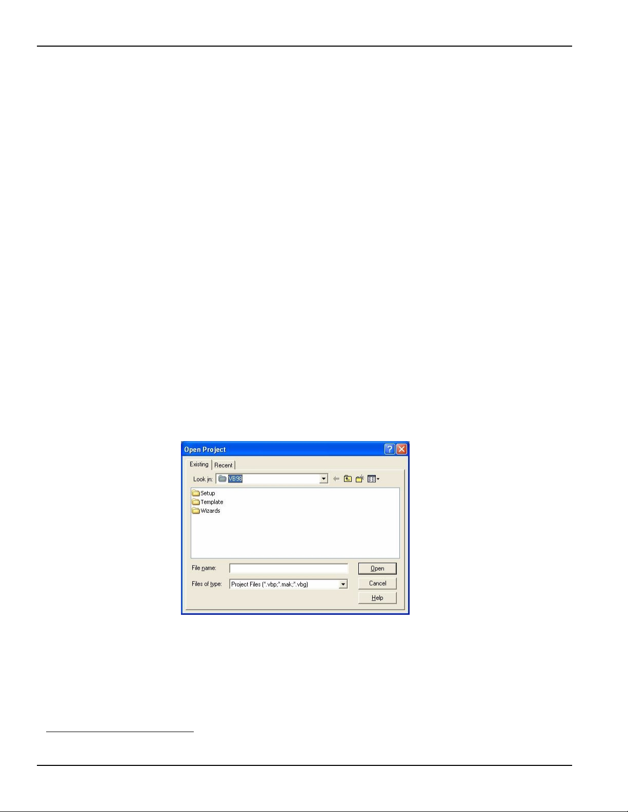
To create a new project, select New Project from the File menu.
To use an existing project:
1. Open the file by selecting Open Project from the File menu. The Open Project dialog box
appears (Figure 1-1).
Figure 1-1
Open Project dialog box
2. Load the project by finding and double-clicking the project file name in the applicable
directory.
Step 2: Include function declarations and constants file (IEEEVB.BAS)
If it is not already included in the project, add the IEEEVB.BAS file as a module to your project. All
Keithley Command Compatible function declarations and constants are contained in this file.
These function declarations and constants are used to develop user self-measurement
applications.
1. National Instruments™ and NI are trademarks of the National Instruments Corporation.
1-2 Return to Section Topics KPXI-488-901-01 Rev. A / January 2007

KPXI Compact GPIB Controller Reference Manual Section 1: Keithley Command Compatible Functions
Step 3: Design the application interface
Add elements, such as a command button, list box, or text box, etc., on the Visual Basic form used
to design the interface. These elements are standard controls from the Visual Basic Toolbox. To
place a needed control on the form:
1. Select the needed control from the Toolbox.
2. Draw the control on the form. Alternatively, to place the default-sized control on the form,
click the form. Use the Select Objects tool to reposition or resize controls.
Step 4: Set control properties
Set control properties from the properties list. To view the properties list, select the desired control
and do one of the following:
• Press F4
• Select the Properties command in the View menu
or
• Click the Properties button on the Toolbar.
Step 5: Write the event codes
The event codes define the action desired when an event occurs. To write the event codes:
1. Double-click the control or form needing event code (the code module will appear).
2. Add new code as needed. All functions that are declared in IEEEVB.BAS can be called to
perform data acquisition operations (refer to Keithley Command Compatible function
reference).
Step 6: Run your application
To run the application, either:
• Press F5
•Select Start from the Run menu
or
• Click the Start icon on the Toolbar
KPXI-488-901-01 Rev. A / January 2007 Return to Section Topics 1-3

Section 1: Keithley Command Compatible Functions KPXI Compact GPIB Controller Reference Manual
Microsoft Visual C/C++
To create a Windows XP/2000 Keithley command compatible library application using the Keithley
Command Compatible function library (which is CEC command-compatible) and Microsoft Visual
C/C++, follow these steps:
Step 1: Enter Visual C/C++ and open or create a project in which you wish to use
Keithley Command Compatible functions
NOTE The project can be a new or existing one.
Step 2: Include function declarations and constants file (IEEE-C.H)
Include IEEE-C.H in the C/C++ source files that call Keithley Command Compatible functions by
adding the following statement in the source file:
#include "IEEE-C.H"
NOTE Keithley Command Compatible function declarations and constants are contained in
IEEE-C.H. Use the functions and constants to develop user self data-acquisition
applications.
Step 3: Build your application
1. Set suitable compile and link options.
2. Select Build from the Build menu (Visual C/C++ 4.0 and higher).
3. Remember to link the Keithley Command Compatible library ieee_32m.lib.
1-4 Return to Section Topics KPXI-488-901-01 Rev. A / January 2007

KPXI Compact GPIB Controller Reference Manual Section 1: Keithley Command Compatible Functions
Keithley Command Compatible function reference
This section contains a detailed description of Keithley Command Compatible library functions,
including the compatible library data types and function reference. The following functions are
arranged alphabetically:
GPIBBOARDPRESENT
Description This function checks if a GPIB board is present in the GPIB system.
Syntax Microsoft C/C++ and Borland C++
char gpib_board_present(void)
Visual Basic
GpibBoardPresent( ) As Long
Return Value 0: if no GPIB is installed
1: if a GPIB board is installed
BOARDSELECT
Description This function selects a board to be the active board.
Syntax Microsoft C/C++ and Borland C++
Parameters board: the board number. The valid value is from 0 to 3
DMACHANNEL
Description This function sets the DMA channel. This function is ignored for the
Syntax Microsoft C/C++ and Borland C++
Parameters chan: DMA channel number
ENTER
void boardselect (long int bd)
Visual Basic
call boardselect (ByVal board As Long)
Model KPXI-488.
void dmachannel (long int c)
Visual Basic
call dmachannel (ByVal chan As Long)
Description This function reads data from a specified device.
Syntax Microsoft C/C++ and Borland C++
long int enter (char *buf, unsigned long maxlen,
unsigned long *len, long int addr,
long int *status)
KPXI-488-901-01 Rev. A / January 2007 Return to Section Topics 1-5

Section 1: Keithley Command Compatible Functions KPXI Compact GPIB Controller Reference Manual
Visual Basic
call enter(buf As String, maxlen As Integer,
len As Integer, addr As Integer, status As Integer)
Parameters buf: the buffer storing the received data
maxlen: the maximum bytes of data to receive. The valid value is from 0 to 65535
len:returns the actual number of received data bytes
addr: the GPIB address of the Talker
status: 0: read data successfully; 8: timeout error
FEATURE
Description This function returns the GPIB board settings or hardware features.
Syntax Microsoft C/C++ and Borland C++
long int feature (long int f)
Visual Basic
GPIBFeature (ByVal f As Long) As Long
Parameters f: the feature or setting information desired. Valid FEATURE values are contained
in
Table 1-1.
Table 1-1
FEATURE parameters
Feature
(Constants)
IEEEListener 0 Checking if ListenerPresent function is supported by
IEEEIOBASE 100 the I/O base address of the board
IEEETIMEOUT 200 the I/O timeout setting of the board
IEEEINPUTEOS 201 the current setting of the input EOS character
IEEEOUTPUTEOS1 202 the current setting of the output EOS character 1
IEEEOUTPUTEOS2 203 the current setting of output EOS character 2
IEEEBOARDSELECT 204 the current active board number
Return Value The value of the feature or setting
INITIALIZE
Description This function opens and initializes a GPIB board.
Syntax Microsoft C/C++ and Borland C++
Features
(Values) Returned Information
the GPIB board; this information value is always 1.
void initialize (long int addr,
long int level)
Visual Basic
call initialize (ByVal addr As Long,
ByVal level As Long)
Parameters addr : GPIB address assigned to the board
level: 0: specifies the board as a system controller
1: specifies the board as a device
1-6 Return to Section Topics KPXI-488-901-01 Rev. A / January 2007

KPXI Compact GPIB Controller Reference Manual Section 1: Keithley Command Compatible Functions
LISTENERPRESENT
Description This function checks if a listener is present on the GPIB system.
Syntax Microsoft C/C++ and Borland C++
char listener_present(long int addr)
Visual Basic
ListenerPresent (ByVal addr As Long) As Long
Parameters addr: the listener address to check
Return Value 0: the specified listener is not present
1: the specified listener is on the GPIB system
PPOLL
Description This function performs a parallel poll and reads the status of devices.
Syntax Microsoft C/C++ and Borland C++
int ppoll (char *poll)
Parameters poll: returned parallel polling status
RARRAY
Description This function receives a block of binary data (up to 64K) from a device defined as
Syntax Microsoft C/C++ and Borland C++
Parameters buf: the buffer storing the received binary data
Return Value 0: read data successfully
Visual Basic
call ppoll(poll As Integer)
the talker. The GPIB addressing must be performed using the transmit function.
long int rarray (void *buf,
unsigned long count, unsigned long *len,
long int *status)
Visual Basic
call rarray(buf As Variant, ByVal count As Long,
l As Integer, status As Integer)
count: the maximum data bytes. The valid value is 0 to 65535
len: returns the actual number of received data bytes
8: timeout error
32: data transfer terminated with EOI
KPXI-488-901-01 Rev. A / January 2007 Return to Section Topics 1-7

Section 1: Keithley Command Compatible Functions KPXI Compact GPIB Controller Reference Manual
RECEIVE
Description This function reads data from a specified device, but does not address a talker.
The GPIB addressing must be performed using the transmit function.
Syntax Microsoft C/C++ and Borland C++
long int receive (char *buf, unsigned long maxlen,
unsigned long *len, long int *status)
Visual Basic
call receive (buf As String, maxlen As Integer,
len As Integer, status As Integer)
Parameters buf: the buffer storing the received data
maxlen: sets maximum bytes of data to receive
len: returns the actual number of received data bytes
Return Value 0: read data successfully
8: timeout error
SEND
Description This function sends commands to a specified GPIB device.
Syntax Microsoft C/C++ and Borland C++
Parameters addr: the listener address
Return Value 0: data sent successfully
SETINPUTEOS
Description This function sets the terminating character for input data transfer.
Syntax Microsoft C/C++ and Borland C++
long int send (long int addr, char *buf,
unsigned long maxlen, long int *status)
Visual Basic
call send(addr As Integer, buf As String,
status As Integer)
buf: the buffer storing the data to send
maxlen: sets the maximum number of data bytes to send
8: timeout error
void setinputEOS (long int eos_c)
Visual Basic
call setinputEOS (ByVal eos_c As Long)
Parameters eos_c: the terminating character for input data transfer
SETOUTPUTEOS
Description This function sets the terminating characters for output data transfer.
Syntax Microsoft C/C++ and Borland C++
void setoutputEOS (long int e1, long int e2)
1-8 Return to Section Topics KPXI-488-901-01 Rev. A / January 2007

KPXI Compact GPIB Controller Reference Manual Section 1: Keithley Command Compatible Functions
Visual Basic
call setoutputEOS (ByVal e1 As Long, ByVal e2 As Long)
Parameters e1: the first terminating character for output data transfer
e2: the second terminating character for output data transfer
SETPORT
Description This function sets the I/O address of a GPIB board. This function is not used for
the Model KPXI-488.
Syntax Microsoft C/C++ and Borland C++
void setport (long int bd, unsigned io)
Visual Basic
call setport (ByVal bd As Long, ByVal io As Long)
Parameters bd: the board number
io: the I/O base address set to the device
SETTIMEOUT
Description This function sets the timeout period. The timeout period is the maximum duration
Syntax Microsoft C/C++ and Borland C++
Parameters timeout: the timeout value in milli-seconds (msec)
SPOLL
Description This function performs serial polling and a read of the specified device’s status.
Syntax Microsoft C/C++ and Borland C++
Parameters addr: the address of the device to poll
allowed for a read/write operation.
void settimeout (unsigned long int timeout)
Visual Basic
call settimeout (ByVal timeout As Long)
long int spoll (long int addr, char *poll,
long int *status)
Visual Basic
call spoll(ByVal addr As Integer, poll As Integer,
status As Integer)
poll: returns result of serial polling
Return Value 0: data sent successfully
8: timeout error
KPXI-488-901-01 Rev. A / January 2007 Return to Section Topics 1-9

Section 1: Keithley Command Compatible Functions KPXI Compact GPIB Controller Reference Manual
SRQ
Description This function checks if a device is requesting service.
Syntax Microsoft C/C++ and Borland C++
char srq(void)
Visual Basic
srq ( ) As Long
Return Value 0: the device is not requesting service
1: the device is requesting service
TARRAY
Description This function sends a block of binary data from memory to the devices defined as
listeners. The GPIB addressing must be performed using the transmit function.
Syntax Microsoft C/C++ and Borland C++
long int tarray (void *buf,
unsigned long count, long int eoi,
long int *status)
Parameters buf: the buffer storing the data to send
Return Value 0: read data successfully
TRANSMIT
Description This function sends GPIB commands and data according to a specified string
Syntax Microsoft C/C++ and Borland C++
Parameters cmd: the buffer containing the command string and data to send.
Visual Basic
call tarray (buf as variant, ByVal count As Long,
ByVal eoi As Integer, status As Integer)
count: the maximum number of data bytes to be transmitted
eoi: enable or disable EOI mode of the device. 0 = disable EOI; 1 = enable EOI
8: timeout error
32: data transfer terminated with EOI
composed a series of GPIB commands and data.
long int transmit (char * cmd,
unsigned maxlen, long int * status);
Visual Basic
call transmit(cmd As String, status As Integer)
The valid cmd string values are contained in Table 1-2.
maxlen: the maximum number of command string bytes to send.
Return Value status:
0: sent command and data successfully
1: illegal command syntax
8: timeout error
16: unknown command
32: data transfer terminated with EOI
1-10 Return to Section Topics KPXI-488-901-01 Rev. A / January 2007

KPXI Compact GPIB Controller Reference Manual Section 1: Keithley Command Compatible Functions
Table 1-2
TRANSMIT command string parameters
Commands Description Example
LISTEN Sets the addresses of the listeners. The
values following LISTEN are the GPIB
addresses of the listeners.
TALK Sets the address of the talker. The
values following TALK are the GPIB
addresses of the talker. There is only
one talker at a time.
SEC Sets the second address of the talker or
listener. This command should follow
TALK or LISTEN.
UNT Untalk. "UNT"
UNL Unlisten. "UNL"
MTA My Talk Address. Assigns the active
GPIB board as the talker.
MLA My Listen Address. Assigns the active
GPIB board as the listener.
DATA Starts the data part. Before the DATA
command, the GPIB board has to be set
as the talker. Strings are enclosed by
quotes(') and sent as characters.
"LISTEN 1 2 3"
meaning: config devices whose GPIB
address are 1, 2 and 3, as listeners.
"TALK 0"
meaning: config device whose GPIB
address is 0, as talker.
"TALK 0 SEC 1"
meaning: config device whose primary GPIB
address is 0 and secondary address is 1 as
talker.
"MTA"
"MLA"
"DATA 'hello' 13 10"
END Sends terminator characters. DATA
command should be called before this
command.
REN Remote Enable "REN"
EOI End-or-Identify. The data bytes following
EOI are the last bytes to transmit. The
last byte is sent with the EOI signal.
GTL Go To L o c a l "GTL"
SPE Serial Poll Enable "SPE"
SPD Serial Poll Disable "SPD"
PPC Parallel Poll Configure "PPC"
PPD Parallel Poll Disable "PPD"
PPU Parallel Poll Unconfigure "PPU"
DCL Device Clear "DCL"
LLO Local Lockout "LLO"
CMD Starts GPIB command. The values
followed by CMD are treated as GPIB
command messages and sent as binary
values.
GET Group Execute Trigger "GET"
SDC Selected Device Clear "SDC"
TCT Take Control "TCT"
IFC Interface Clear "IFC"
"DATA '*IDN?' END" meaning: send data
message "*IDN?" and then send terminator
bytes
"DATA '*IDN?' EOI 10"
meaning: send data message "*IDN?" and
then send line feed with EOI signal.
"CMD 20"
meaning: send GPIB command message,
Device Clear (DCL).
KPXI-488-901-01 Rev. A / January 2007 Return to Section Topics 1-11

Section 1: Keithley Command Compatible Functions KPXI Compact GPIB Controller Reference Manual
WAITSRQDEVICE
Description This function waits until a device is requesting service or a timeout error occurs.
Syntax Microsoft C/C++ and Borland C++
long int waitSRQDevice (long int addr,
char *poll, long int *status)
Parameters addr: the device address
poll: the returned poll status
status: indicates whether or not a serial poll was performed
1-12 Return to Section Topics KPXI-488-901-01 Rev. A / January 2007
 Loading...