

Page 1

www.keithley.com
KPXI Compact GPIB Controller
Quick Start Guide
KPXI-488-903-01 Rev. A / January 2007
A GREATER MEASURE OF CONFIDENCE
ECA 42912
Page 2

WARRANTY
Keithley Instruments, Inc. warrants this product to be free from defects in material and workmanship for a period of
1 year from date of shipment.
Keithley Instruments, Inc. warrants the following items for 90 days from the date of shipment: probes, cables,
rechargeable batteries, diskettes, and documentation.
During the warranty period, we will, at our option, either repair or replace any product that proves to be defective.
To exercise this warranty, write or call your local Keithley Instruments representative, or contact
Keithley Instruments headquarters in Cleveland, Ohio. You will be given prompt assistance and return instructions.
Send the product, transportation prepaid, to the indicated service facility. Repairs will be made and the product
returned, transportation prepaid. Repaired or replaced products are warranted for the balance of the original
warranty period, or at least 90 days.
LIMITATION OF WARRANTY
This warranty does not apply to defects resulting from product modification without Keithley Instruments’ express
written consent, or misuse of any product or part. This warranty also does not apply to fuses, software,
non-rechargeable batteries, damage from battery leakage, or problems arising from normal wear or failure to follow
instructions.
THIS WARRANTY IS IN LIEU OF ALL OTHER WARRANTIES, EXPRESSED OR IMPLIED, INCLUDING ANY
IMPLIED WARRANTY OF MERCHANTABILITY OR FITNESS FOR A PARTICULAR USE. THE REMEDIES
PROVIDED HEREIN ARE BUYER’S SOLE AND EXCLUSIVE REMEDIES.
NEITHER KEITHLEY INSTRUMENTS, INC. NOR ANY OF ITS EMPLOYEES SHALL BE LIABLE FOR ANY
DIRECT, INDIRECT, SPECIAL, INCIDENTAL OR CONSEQUENTIAL DAMAGES ARISING OUT OF THE USE OF
ITS INSTRUMENTS AND SOFTWARE EVEN IF KEITHLEY INSTRUMENTS, INC., HAS BEEN ADVISED IN
ADVANCE OF THE POSSIBILITY OF SUCH DAMAGES. SUCH EXCLUDED DAMAGES SHALL INCLUDE, BUT
ARE NOT LIMITED TO: COSTS OF REMOVAL AND INSTALLATION, LOSSES SUSTAINED AS THE RESULT
OF INJURY TO ANY PERSON, OR DAMAGE TO PROPERTY.
A G R E A T E R M E A S U R E O F C O N F I D E N C E
Keithley Instruments, Inc.
Corporate Headquarters • 28775 Aurora Road • Cleveland, Ohio 44139
440-248-0400 • Fax: 440-248-6168 • 1-888-KEITHLEY (534-8453) • www.keithley.com
12/06
Page 3

KPXI
Compact GPIB Controller
Quick Start Guide
©2007, Keithley Instruments, Inc.
Document Number:
All rights reserved.
Cleveland, Ohio, U.S.A.
KPXI-488-903-01 Rev. A / January 2007
Page 4

Manual Print History KPXI Compact GPIB Controller Quick Start Guide
Manual Print History
The print history shown below lists the printing dates of all Revisions and Addenda created for this
manual. The Revision Level letter increases alphabetically as the manual undergoes subsequent
updates. Addenda, which are released between Revisions, contain important change information that the
user should incorporate immediately into the manual. Addenda are numbered sequentially. When a new
Revision is created, all Addenda associated with the previous Revision of the manual are incorporated
into the new Revision of the manual. Each new Revision includes a revised copy of this print history page.
Revision A (Document Number KPXI-488-903-01)................................... January 2007
All Keithley Instruments product names are trademarks or registered trademarks of Keithley Instruments, Inc.
Other brand names are trademarks or registered trademarks of their respective holders.
KPXI-488-903-01 Rev. A / January 2007
Page 5

The following safety precautions should be observed before using this product and any associated instrumentation. Although
some instruments and accessories would normally be used with non-hazardous voltages, there are situations where hazardous
conditions may be present.
This product is intended for use by qualified personnel who recognize shock hazards and are familiar with the safety precautions
required to avoid possible injury. Read and follow all installation, operation, and maintenance information carefully before using
the product. Refer to the manual for complete product specifications.
If the product is used in a manner not specified, the protection provided by the product may be impaired.
The types of product users are:
Responsible body is the individual or group responsible for the use and maintenance of equipment, for ensuring that the
equipment is operated within its specifications and operating limits, and for ensuring that operators are adequately trained.
Operators use the product for its intended function. They must be trained in electrical safety procedures and proper use of the
instrument. They must be protected from electric shock and contact with hazardous live circuits.
Maintenance personnel perform routine procedures on the product to keep it operating properly, for example, setting the line
voltage or replacing consumable materials. Maintenance procedures are described in the manual. The procedures explicitly state
if the operator may perform them. Otherwise, they should be performed only by service personnel.
Safety Precautions
Service personnel are trained to work on live circuits, and perform safe installations and repairs of products. Only properly
trained service personnel may perform installation and service procedures.
Keithley Instruments products are designed for use with electrical signals that are rated Measurement Category I and
Measurement Category II, as described in the International Electrotechnical Commission (IEC) Standard IEC 60664. Most
measurement, control, and data I/O signals are Measurement Category I and must not be directly connected to mains voltage or
to voltage sources with high transient over-voltages. Measurement Category II connections require protection for high transient
over-voltages often associated with local AC mains connections. Assume all measurement, control, and data I/O connections are
for connection to Category I sources unless otherwise marked or described in the Manual.
Exercise extreme caution when a shock hazard is present. Lethal voltage may be present on cable connector jacks or test
fixtures. The American National Standards Institute (ANSI) states that a shock hazard exists when voltage levels greater than
30V RMS, 42.4V peak, or 60VDC are present. A good safety practice is to expect that hazardous voltage is present in any
unknown circuit before measuring.
Operators of this product must be protected from electric shock at all times. The responsible body must ensure that operators
are prevented access and/or insulated from every connection point. In some cases, connections must be exposed to potential
human contact. Product operators in these circumstances must be trained to protect themselves from the risk of electric shock.
If the circuit is capable of operating at or above 1000 volts, no conductive part of the circuit may be exposed.
Do not connect switching cards directly to unlimited power circuits. They are intended to be used with impedance limited sources.
NEVER connect switching cards directly to AC mains. When connecting sources to switching cards, install protective devices to
limit fault current and voltage to the card.
Before operating an instrument, make sure the line cord is connected to a properly grounded power receptacle. Inspect the
connecting cables, test leads, and jumpers for possible wear, cracks, or breaks before each use.
12/06
Page 6

When installing equipment where access to the main power cord is restricted, such as rack mounting, a separate main input
power disconnect device must be provided, in close proximity to the equipment and within easy reach of the operator.
For maximum safety, do not touch the product, test cables, or any other instruments while power is applied to the circuit under
test. ALWAYS remove power from the entire test system and discharge any capacitors before: connecting or disconnecting
cables or jumpers, installing or removing switching cards, or making internal changes, such as installing or removing jumpers.
Do not touch any object that could provide a current path to the common side of the circuit under test or power line (earth) ground.
Always make measurements with dry hands while standing on a dry, insulated surface capable of withstanding the voltage being
measured.
The instrument and accessories must be used in accordance with its specifications and operating instructions or the safety of the
equipment may be impaired.
Do not exceed the maximum signal levels of the instruments and accessories, as defined in the specifications and operating
information, and as shown on the instrument or test fixture panels, or switching card.
When fuses are used in a product, replace with same type and rating for continued protection against fire hazard.
Chassis connections must only be used as shield connections for measuring circuits, NOT as safety earth ground connections.
If you are using a test fixture, keep the lid closed while power is applied to the device under test. Safe operation requires the use
of a lid interlock.
If a screw is present, connect it to safety earth ground using the wire recommended in the user documentation.
!
The symbol on an instrument indicates that the user should refer to the operating instructions located in the manual.
The symbol on an instrument shows that it can source or measure 1000 volts or more, including the combined effect of
normal and common mode voltages. Use standard safety precautions to avoid personal contact with these voltages.
The symbol on an instrument shows that the surface may be hot. Avoid personal contact to prevent burns.
The symbol indicates a connection terminal to the equipment frame.
The WARNING heading in a manual explains dangers that might result in personal injury or death. Always read the associated
information very carefully before performing the indicated procedure.
The CAUTION heading in a manual explains hazards that could damage the instrument. Such damage may invalidate the
warranty.
Instrumentation and accessories shall not be connected to humans.
Before performing any maintenance, disconnect the line cord and all test cables.
To maintain protection from electric shock and fire, replacement components in mains circuits, including the power transformer,
test leads, and input jacks, must be purchased from Keithley Instruments. Standard fuses, with applicable national safety
approvals, may be used if the rating and type are the same. Other components that are not safety related may be purchased
from other suppliers as long as they are equivalent to the original component. (Note that selected parts should be purchased only
through Keithley Instruments to maintain accuracy and functionality of the product.) If you are unsure about the applicability of a
replacement component, call a Keithley Instruments office for information.
To clean an instrument, use a damp cloth or mild, water based cleaner. Clean the exterior of the instrument only. Do not apply
cleaner directly to the instrument or allow liquids to enter or spill on the instrument. Products that consist of a circuit board with
no case or chassis (e.g., data acquisition board for installation into a computer) should never require cleaning if handled
according to instructions. If the board becomes contaminated and operation is affected, the board should be returned to the
factory for proper cleaning/servicing.
Page 7

Table of Contents
Section Topic Page
1 Introduction............................................................................................. 1-1
Introduction ................................................................................................. 1-2
Overview .............................................................................................. 1-2
Performance......................................................................................... 1-2
Compatibility......................................................................................... 1-2
Features ............................................................................................... 1-2
Manual addenda......................................................................................... 1-3
Safety symbols and terms .......................................................................... 1-3
Specifications.............................................................................................. 1-3
GPIB bus properties............................................................................. 1-3
Certificates ........................................................................................... 1-3
General specifications.......................................................................... 1-4
Unpacking and inspection........................................................................... 1-4
Inspection for damage.......................................................................... 1-4
Shipment contents ............................................................................... 1-4
Instruction manual................................................................................ 1-4
Repacking for shipment........................................................................ 1-5
Software support......................................................................................... 1-5
2 Installation and configuration ............................................................ 2-1
Introduction ................................................................................................. 2-2
Software installation description ................................................................. 2-2
Installation requirements............................................................................. 2-2
Driver installation ........................................................................................ 2-3
Hardware installation .................................................................................. 2-4
Installation procedure........................................................................... 2-4
PXI configuration.................................................................................. 2-4
Cabling........................................................................................................ 2-5
Using the Keithley GPIB Configuration Utility ............................................. 2-8
Using the Keithley Instruments KPXI-488 Diagnostic Tool ......................... 2-9
3 Using a GPIB........................................................................................... 3-1
Introduction ................................................................................................. 3-2
GPIB connection configuration ................................................................... 3-2
Data lines ............................................................................................. 3-3
Handshake lines................................................................................... 3-3
System management lines................................................................... 3-3
Model KPXI-488 block diagram .................................................................. 3-4
Appendix Topic Page
A Specifications......................................................................................... A-1
Index ........................................................................................................................... I-1
Page 8

Table of Contents KPXI Compact GPIB Controller Quick Start Guide
This page left blank intentionally.
ii KPXI-488-903-01 Rev. A / January 2007
Page 9

List of Figures
Section Figure Title Page
2 Figure 2-1 InstallShield® Wizard ..................................................................... 2-3
Figure 2-2 Restart system............................................................................... 2-4
Figure 2-3 Linear connection configuration..................................................... 2-6
Figure 2-4 Star connection configuration ........................................................ 2-7
Figure 2-5 Keithley GPIB Configuration Utility ................................................ 2-8
Figure 2-6 GPIB Interface & Bus Setting ........................................................ 2-8
Figure 2-7 Keithley KPXI-488 Diagnostic Tool ................................................ 2-9
3 Figure 3-1 Standard GPIB connector .............................................................. 3-2
Figure 3-2 Model KPXI-488 block diagram ..................................................... 3-4
Page 10

List of Figures KPXI Compact GPIB Controller Quick Start Guide
This page left blank intentionally.
iv KPXI-488-903-01 Rev. A / January 2007
Page 11

List of Tables
Section Figure Title Page
1 Table 1-1 Power requirements....................................................................... 1-4
3 Table 3-1 GPIB connector line....................................................................... 3-3
Page 12

List of Tables KPXI Compact GPIB Controller Quick Start Guide
This page left blank intentionally.
vi KPXI-488-903-01 Rev. A / January 2007
Page 13

In this section:
Top ic Pa ge
Introduction ....................................................................................... 1-2
Manual addenda ................................................................................ 1-3
Safety symbols and terms ............................................................... 1-3
Specifications.................................................................................... 1-3
Section 1
Introduction
Overview....................................................................................... 1-2
Performance ................................................................................. 1-2
Compatibility ................................................................................. 1-2
Features ....................................................................................... 1-2
GPIB bus properties ..................................................................... 1-3
Certificates.................................................................................... 1-3
General specifications .................................................................. 1-4
Unpacking and inspection ............................................................... 1-4
Inspection for damage .................................................................. 1-4
Shipment contents........................................................................ 1-4
Instruction manual ........................................................................ 1-4
Repacking for shipment ................................................................ 1-5
Software support............................................................................... 1-5
Page 14

Section 1: Introduction KPXI Compact GPIB Controller Quick Start Guide
Introduction
This section contains general information about the Keithley Instruments Model KPXI-488 GPIB
Controller Interface Card.
If you have any questions after reviewing this information, contact your local Keithley Instruments
representative or call one of our applications engineers. Find current contact information at
www.keithley.com.
Overview
Keithley Instruments’ Model KPXI-488 GPIB Controller Interface Card is fully compatible with the
IEEE488.2 instrumentation control and communication standard. The interface card is capable of
controlling up to 14 stand-alone instruments via IEEE488 cables. Designed to meet the
requirements for high performance and maximum programming portability, the 1KB on-board FIFO
buffer (First In First Out) and block transfer mode provide up to 1.5MB per second GPIB transfer
rate.
With the Keithley Command Compatible driver, the National Instruments™ (NI)1 Command
Compatible driver, and VISA support (Virtual Instrument Software Architecture), the
Model KPXI-488 provides extensive compatibility with your existing applications and instrument
drivers.
Performance
This newly-designed Model KPXI-488 GPIB Controller Interface Card works with all PXI standard
2.2 compliant controllers and chassis. An on-board 1KB FIFO is placed between the GPIB bus and
PCI controller to buffer GPIB read/write operations. The FIFO eliminates the gap between the
slower GPIB bus (which is about 1.5MB per second) and the fast PXI bus (132MB per second),
dramatically increasing overall system performance.
Compatibility
The Model KPXI-488 provides complete software support, including a driver API (application
program interface) that is command compatible with Keithley Instruments' and Capital Equipment
Corporations' IEEE_32M.DLL, and a driver API that is NI command compatible with GPIB32.DLL
(programs written based on these DLL's can be executed on the Model KPXI-488 without any
major modification, often no modifications at all). Industry-standard VISA libraries are also
supported to ensure compatibility with applications utilizing VISA. Through design, the Model
KPXI-488 is plug-and-play compatible with your existing applications.
Features
The Model KPXI-488 GPIB Controller Interface Card provides the following advanced features:
• Fully compatible with the IEEE488.2 standard
• Supports a 32-bit PXI bus
• Up to 1.5MB per second data transfer rates
• On-board 1KB FIFO for read/write operations
• Command compatible driver API for Keithley Instruments, NI, and VISA.
• Interactive utility for testing and diagnostics
1. National Instruments™ and NI are trademarks of the National Instruments Corporation.
1-2 Return to Section Topics KPXI-488-903-01 Rev. A / January 2007
Page 15

KPXI Compact GPIB Controller Quick Start Guide Section 1: Introduction
Manual addenda
Any improvements or changes concerning the Model KPXI-488 or manual will be explained in an
addendum included with the manual. Be sure to note these changes and incorporate them into the
manual.
Safety symbols and terms
The following symbols and terms may be found on the Model KPXI-488 or used in this manual:
The symbol indicates that the user should refer to the operating instructions located in the
!
manual.
The symbol shows that high voltage may be present on the terminal(s). Use standard safety
precautions to avoid personal contact with these voltages.
The symbol on an instrument shows that the surface may be hot. Avoid personal contact to
prevent burns.
The WARNING heading used in this manual explains dangers that might result in personal injury
or death. Always read the associated information very carefully before performing the indicated
procedure.
The CAUTION heading used in this manual explains hazards that could damage the switch. Such
damage may invalidate the warranty.
Specifications
Detailed Model KPXI-488 specifications are included in Appendix A; a specification overview is
presented below. Check the Keithley Instruments website (www.keithley.com) for latest updates to
the specifications.
GPIB bus properties
• Up to 14 instruments can be connected to one controller
• Maximal 1.5MB per second data transfer rate
• Cable length:
– 2 meters between each instrument (suggested)
– 20 meters total cable length
• Data transfer mode: 8 bits parallel
• Handshake: 3-wire handshake, reception of each data byte is acknowledged
Certificates
• Safety: European Directive 73/23/EEC, EN60950
• EMC/EMI: European Directive 89/336/EEC, EN55022, EN55024
KPXI-488-903-01 Rev. A / January 2007 Return to Section Topics 1-3
Page 16

Section 1: Introduction KPXI Compact GPIB Controller Quick Start Guide
General specifications
• I/O connector: IEEE488 standard 24-pin connector
• Operating temperature: 0°C to 55ºC
• Storage temperature: -20°C to 80ºC at 5% to 95% humidity
• Relative humidity: 5% to 95%, non-condensing
Table 1-1
Power requirements
Current
400mA (typical)
750mA (maximum)
• Dimensions (not including connectors): 135mm x 107mm
Unpacking and inspection
CAUTION The Model KPXI-488 contains electro-static sensitive components that can
easily be damaged by static electricity. Handle the module on a grounded antistatic mat. The operator should be wearing an anti-static wristband, grounded
at the same point as the anti-static mat.
Inspection for damage
The Model KPXI-488 was carefully inspected electrically and mechanically before shipment. After
unpacking all items from the shipping carton, check for any obvious signs of physical damage that
may have occurred during transit. Report any damage to the shipping agent immediately. Save the
original packing carton for possible future shipment.
Shipment contents
The following items are included with every Model KPXI-488 order:
• Model KPXI-488
• A CD (KPXI-488-950-01) that contains drivers, manual, and software for all KPXI Series
products
Instruction manual
The product CD-ROM contains this Quick Start Guide and a Reference Manual for the Model
KPXI-488. The reference manual provides programming information on Keithley Command
Compatible functions and NI command compatible functions (syntax as well as examples in C/
C++, Visual Basic, etc.).
Always check the Keithley Instruments website (www.keithley.com) for the latest revision of the
manual. The latest manual can be downloaded (in PDF format) from the website.
1-4 Return to Section Topics KPXI-488-903-01 Rev. A / January 2007
Page 17

KPXI Compact GPIB Controller Quick Start Guide Section 1: Introduction
Repacking for shipment
Should it become necessary to return the Model KPXI-488 for repair, carefully pack the unit in its
original packing carton or the equivalent, and follow these instructions:
• Call the Repair Department for a Return Material Authorization (RMA) number. Call the
Repair Department toll-free at 1-800-552-1115 (US only). Outside of the US, Worldwide
Service Centers contact information is available at www.keithley.com.
• Advise as to the warranty status of the Model KPXI-488.
• Write ATTENTION REPAIR DEPARTMENT and the RMA number on the shipping label.
• Fill out and include the Service Form located at the back of this manual.
Software support
The Model KPXI-488 provides device drivers for Windows® XP/2000 operating systems. The
Keithley Instruments GPIB driver package provides a diagnostic utility to test your
Model KPXI-488 GPIB card, as well as programming samples and source codes for Microsoft®
Visual Basic and Visual C++. The Model KPXI-488 also offers support for
National Instruments™ LabVIEW™ and LabWindows/CVI™. Find the Keithley Instruments GPIB
driver package located on the supplied CD. Refer to
for detailed software installation instructions. Refer to Section 3 for a description of the operational
theory of a GPIB (General Purpose Interface Bus) and the basic architecture of Keithley
Instruments Model KPXI-488 GPIB interface card. Contact Keithley Instruments for other
operating system support.
Software installation description in Section 2
For LabVIEW™ and LabWindows/CVI™ support, Keithley Instruments recommends the
installation of the NI Command Compatible Driver. For LabVIEW programmers, Keithley
Instruments supplies a set of LabVIEW GPIB VIs that are optimized for use with the
KPXI-488.
KPXI-488-903-01 Rev. A / January 2007 Return to Section Topics 1-5
Page 18

Section 1: Introduction KPXI Compact GPIB Controller Quick Start Guide
This page left blank intentionally.
1-6 Return to Section Topics KPXI-488-903-01 Rev. A / January 2007
Page 19

In this section:
Top ic Pa ge
Introduction ....................................................................................... 2-2
Software installation description..................................................... 2-2
Installation requirements ................................................................. 2-2
Driver installation.............................................................................. 2-3
Hardware installation........................................................................ 2-4
Cabling............................................................................................... 2-5
Section 2
Installation and configuration
Installation procedure ................................................................... 2-4
PXI configuration .......................................................................... 2-4
Using the Keithley GPIB Configuration Utility ............................... 2-8
Using the Keithley Instruments KPXI-488 Diagnostic Tool........... 2-9
Page 20

Section 2: Installation and configuration KPXI Compact GPIB Controller Quick Start Guide
Introduction
This section describes unpacking information and describes how to install the Model KPXI-488. To
install the Model KPXI-488 in a system, after reviewing the
Installation requirements, complete (in this order):
1. Driver installation
2. Hardware installation
3. Cabling
See Using the Keithley GPIB Configuration Utility and Using the Keithley Instruments KPXI-488
Diagnostic Tool for information on using these supplied utilities.
WARNING The procedures in this section are intended only for qualified service
personnel. Do not perform these procedures unless you are qualified to do so.
Failure to recognize and observe normal safety precautions could result in
personal injury or death.
CAUTION The Model KPXI-488 contains electro-static sensitive components that can
easily be damaged by static electricity. Handle the module on a grounded
anti-static mat. The operator should be wearing an anti-static wristband,
grounded at the same point as the anti-static mat.
Software installation description and
CAUTION Do not apply power to the card if it has been damaged.
Software installation description
This section describes the software installation for the Keithley Instruments Model KPXI-488.
Driver installation is outlined along with information on using the Keithley GPIB Configuration
Utility and the KPXI-488 Diagnostic Tool.
The Keithley Instruments Model KPXI-488 is delivered with a GPIB driver package that supports
Windows
compatible with your current applications. They provide both Keithley Command Compatible
NI2 command compatible APIs3 and software support for program developers using Microsoft®
programming languages like Visual Basic®, Visual C, as well as LabVIEW™ and LabWindows/
CVI™.
Instruments Model KPXI-488 Reference Manual (KPXI-488-901-01) for complete function and
programming information.
®
XP/2000 Operating Systems. The KPXI-488 drivers are designed to be command
4
The KPXI-488 also supports industry-standard VISA5 libraries. Refer to the Keithley
Installation requirements
Review the following list of important requirements that must be taken into account prior to
installing the Model KPXI-488:
I. The KPXI-488 is not compatible with Dynamic Link Libraries (DLL) from other IEEE
interface board suppliers. Due to the KPXI-488's command compatibility with National
Instruments™ and Capital Equipment Corporation (CEC), the installation program for the
KPXI-488 will install a DLL that has the same name as those provided by National
1
and
1. Derived from the Capital Equipment Corporation (CEC) command set.
2. National Instruments™ and NI™ are trademarks of the National Instruments Corporation. Other brand names are
trademarks or registered trademarks of their respective holders.
3. API—Application Program Interface
4. CVI—C for Virtual Instrumentation
5. VISA—Virtual Instrument Software Architecture
2-2 Return to Section Topics KPXI-488-903-01 Rev. A / January 2007
Page 21

KPXI Compact GPIB Controller Quick Start Guide Section 2: Installation and configuration
Instruments (GPIB32.DLL) and CEC (and previous Keithley) interfaces (IEEE_32M.DLL).
For proper installation of the KPXI-488 hardware and software, you must remove any
existing GPIB interfaces from your PC and uninstall any currently installed GPIB
drivers. Failure to uninstall any existing GPIB drivers before installing the KPXI-488
command compatible drivers can, and likely will cause system problems.
II. For LabVIEW™ and LabWindows/CVI™ support, Keithley Instruments recommends
the installation of the NI Command Compatible Driver. For LabVIEW programmers,
Keithley Instruments supplies a set of LabVIEW GPIB VIs that are optimized for use with the
KPXI-488.
The procedure to install the KPXI-488 driver package and utilities is outlined in Driver installation.
Driver installation
Use the following procedure as a guideline to install the GPIB Driver Package on your computer:
1. Insert the Keithley Instruments KPXI driver CD.
2. Allow the CD to auto run and begin the setup program. If setup does not start, open the CD
using Windows Explorer and execute setup.exe to launch the setup program. Once the
setup screen appears, click on GPIB in the left navigation menu (shown in Figure 2-1).
3. You may choose to install the Keithley Command Compatible Driver or the NI command
compatible driver. Refer to Model KPXI-488 Reference Manual (KPXI-488-901-01) for
available functions of either compatible driver.
Figure 2-1
InstallShield® Wizard
4. Follow the InstallShield® Wizard prompts to complete the setup procedure.
5. When setup finishes, please reboot your system.
KPXI-488-903-01 Rev. A / January 2007 Return to Section Topics 2-3
Page 22

Section 2: Installation and configuration KPXI Compact GPIB Controller Quick Start Guide
Figure 2-2
Restart system
Hardware installation
CAUTION The Model KPXI-488 contains electro-static sensitive components that can
easily be damaged by static electricity. Handle the module on a grounded
anti-static mat. The operator should be wearing an anti-static wristband,
grounded at the same point as the anti-static mat.
NOTE Install software before installing the hardware (refer to Software installation description).
Installation procedure
The following instructions outline Model KPXI-488 installation:
1. Turn off your PXI controller.
2. Turn off all accessories (printer, modem, monitor, etc.) connected to your PXI controller.
3. Make a PXI peripheral slot available by removing a slot cover if necessary.
4. Before handling the PXI cards, discharge any static buildup on your body by touching the
metal case of the PXI chassis. Hold the handle and do not touch the components.
5. Position the board into the PXI slot you selected.
6. Secure the card in place by lifting the handle and tightening the top and bottom screws on
the faceplate.
After completing the hardware installation procedure, install cables as desired (refer to Cabling for
information).
PXI configuration
Plug-and-play
As a plug-and-play component, the card requests an interrupt number via its PCI controller
(Peripheral Component Interconnect). The system BIOS (Basic Input Output System) responds
with an interrupt assignment based on the card information and on known system parameters.
These system parameters are determined by the installed drivers and the hardware load seen by
the system.
Configuration
The board configuration is done on a board-by-board basis for all PXI boards on your system.
Because configuration is controlled by the system and software, there is no jumper setting
required for base-address, DMA (Direct Memory Access), and interrupt IRQ (Interrupt Request).
2-4 Return to Section Topics KPXI-488-903-01 Rev. A / January 2007
Page 23

KPXI Compact GPIB Controller Quick Start Guide Section 2: Installation and configuration
The configuration is subject to change with every boot of the system as new boards are added or
removed.
Troubleshooting
If your system doesn't boot or if you experience erratic operation with your PXI board in place, it's
likely caused by an interrupt conflict (perhaps the BIOS setup is incorrectly configured). In general,
the solution — once you determine it is not a simple oversight — is to consult the BIOS
documentation that comes with your system or computer.
In Windows 2000 or WinXP, if your KPXI-488 shows up in Device Manager, but has an error code
which indicates that no resources are in use, a simple change in the BIOS may resolve the
matter. The BIOS setting for Plug-and-Play Aware OS should be set to NO. This setting will allow
the PnP BIOS and motherboard chipset hardware to assign hardware resources to cards such as
the KPXI-488. Windows 2000 or WinXP will then make use of these assigned resources.
Cabling
For optimal GPIB throughput, adhere to the following bulleted cabling guidelines. These cabling
guidelines include instrument number and cable distance:
• The longest distance between two devices is 4 meters; the average GPIB bus distance
between all devices should be less than 2 meters.
• The total GPIB bus distance should be less than 20 meters.
• The total number of connected devices must be less than 15 (including computer itself), with
at least two-thirds of the devices powered on (in a power-on status).
Users can connect devices in a linear configuration (refer to Figure 2-3), star configuration (refer to
Figure 2-4), or combination of the two configurations.
NOTE To lower the total current load of the configuration, limit the number of cable connections
on each individual instrument to three or less. For example, to lower the required current
load when using the configuration shown in
connections on Instrument A. Move one of the cable connections from Instrument A to a
different instrument, thus making this configuration into a combination of linear and star
configurations.
Figure 2-4, reduce the number of
KPXI-488-903-01 Rev. A / January 2007 Return to Section Topics 2-5
Page 24

Section 2: Installation and configuration KPXI Compact GPIB Controller Quick Start Guide
Figure 2-3
Linear connection configuration
Model KPXI-488
GPIB Controller Card
PXI Controller
Instrument A
Instrument B
Instrument C
2-6 Return to Section Topics KPXI-488-903-01 Rev. A / January 2007
Page 25

KPXI Compact GPIB Controller Quick Start Guide Section 2: Installation and configuration
Figure 2-4
Star connection configuration
Model KPXI-488
GPIB Controller Card
PXI Controller
Instrument C
Instrument A
Instrument B
Instrument D
KPXI-488-903-01 Rev. A / January 2007 Return to Section Topics 2-7
Page 26
Section 2: Installation and configuration KPXI Compact GPIB Controller Quick Start Guide
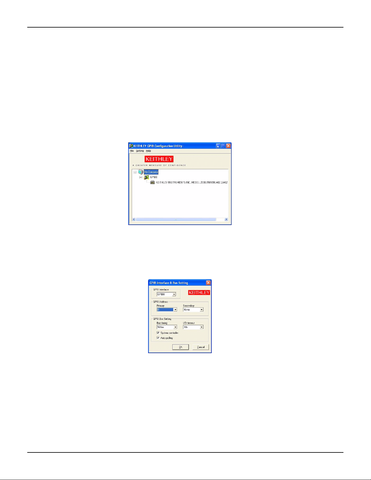
Using the Keithley GPIB Configuration Utility
The driver package provides a configuration utility program (Keithley Instrument's GPIB
Configuration Utility) to let you configure the KPXI-488's bus address, bus timing, I/O timeout,
whether the board is a system controller, and to enable auto-polling.
To launch the configuration utility:
1. From Windows® Start, select All Programs.
2. From the programs selection, select Keithley Instruments => KPXI-488 =>
KPXI-488 Configuration Utility. The utility window as shown in Figure 2-5 will open.
Figure 2-5
Keithley GPIB Configuration Utility
Double-clicking on the interface icon such as GPIB0 as shown in Figure 2-5 opens up the
KPXI-488 configuration dialog window as shown in Figure 2-6. From this dialog window, you can
set a variety of parameters for operating your interface board.
Figure 2-6
GPIB Interface & Bus Setting
If you change any settings, press OK to set the changes. Make sure to save configuration changes
by going to: Setting => Save Configuration in the KPXI-488 Configuration Utility window.
2-8 Return to Section Topics KPXI-488-903-01 Rev. A / January 2007
Page 27

KPXI Compact GPIB Controller Quick Start Guide Section 2: Installation and configuration
Using the Keithley Instruments KPXI-488 Diagnostic Tool
The KPXI-488 Diagnostic Tool lets you communicate with any GPIB instrument by writing
command strings to your instrument and reading the results.
To launch the diagnostic tool:
1. From Windows® Start, select All Programs.
2. From the programs selection, select Keithley Instruments => KPXI-488 => KPXI-488
Diagnostic Tool.
The diagnostic tool window as shown in Figure 2-7 will open.
Figure 2-7
Keithley KPXI-488 Diagnostic Tool
Prior to communicating with your instrument using the KPXI-488 Diagnostic Tool, press the
Initialize KPXI-488 button and set the required parameters. This must be done before any of the
other feature buttons are enabled.
Type command strings to send to your instrument into the GPIB Command String to Send or
Tra nsmit box. Data returned from the instrument will be displayed in the GPIB Received
Message box. All data strings that you send to instruments will be logged in the GPIB commands
previously sent or transmitted box.
KPXI-488-903-01 Rev. A / January 2007 Return to Section Topics 2-9
Page 28

Section 2: Installation and configuration KPXI Compact GPIB Controller Quick Start Guide
This page left blank intentionally.
2-10 Return to Section Topics KPXI-488-903-01 Rev. A / January 2007
Page 29

In this section:
Top ic Page
Introduction ....................................................................................... 3-2
GPIB connection configuration ....................................................... 3-2
Model KPXI-488 block diagram........................................................ 3-4
Section 3
Using a GPIB
Data lines...................................................................................... 3-3
Handshake lines ........................................................................... 3-3
System management lines ........................................................... 3-3
Page 30

Section 3: Using a GPIB KPXI Compact GPIB Controller Quick Start Guide
Introduction
This section describes the operational theory of a GPIB (General Purpose Interface Bus) and the
basic architecture of Keithley Instruments Model KPXI-488 GPIB Controller Interface Card.
GPIB connection configuration
The GPIB has 24 lines (refer to Figure 3-1). These lines can be divided into 16 signal lines and
8 ground-return or shield-drain lines (refer to Table 3-1). The 16 signal lines can be divided into
a set of 8 parallel (8-bit) data transfer bus lines and a set of 8 control lines. These 8 control lines
contain 5 system management lines and 3 handshake lines.
Figure 3-1
Standard GPIB connector
3-2 Return to Section Topics KPXI-488-903-01 Rev. A / January 2007
Page 31

KPXI Compact GPIB Controller Quick Start Guide Section 3: Using a GPIB
Table 3-1
GPIB connector line
GPIB
BUS
24 lines
Type Function
8 data lines
16
signal
lines
8
ground
lines
8 control
lines
1 shield drain line 12 SHIELD
7 ground return lines
5 system
management
lines
3 handshake
lines
No. Description
1 DIO1
2 DIO2
3 DIO3
4 DIO4
13 DIO5
14 DIO6
15 DIO7
16 DIO8
5 EOI
9 IFC
10 SRQ
11 ATN
17 REN
6 DAV
7 NRFD
8 NDAC
18 GND
19 GND
20 GND
21 GND
22 GND
23 GND
24 SIGNAL GROUND
Pin
Data lines
DIO1 to DIO8 carry both data and command messages. All commands (and most data) use 7-bit
ASCII code; the 8th bit (DIO8), is either unused or used for parity check.
Handshake lines
Three handshake lines control the transfer of data/messages between devices:
• DAV (Data Valid): used to indicate the availability and validity of information on the DIO
signal lines.
• NRFD (Not Ready For Data): used to indicate readiness of device(s) to accept data.
• NDAC (Not Data Accepted): used to indicate acceptance of data by device.
System management lines
The following five system management lines manage the flow of control and data bytes across the
interface:
• EOI (End or Identify): used (by a talker) to indicate the end of a multiple-byte transfer
sequence or, in conjunction with ATN (by a controller), to execute a polling sequence.
• IFC (Interface Clear): used (by a controller) to place the interface system, portions of which
are contained in all interconnected devices, in a known quiescent state.
• SRQ (Service Request): used by a device to indicate the need for attention and to request
an interruption of the current sequence of events.
• ATN (Attention): used (by a controller) to specify how data on the Digital I/O signal lines
are to be interpreted, and which devices must respond to the data.
KPXI-488-903-01 Rev. A / January 2007 Return to Section Topics 3-3
Page 32

Section 3: Using a GPIB KPXI Compact GPIB Controller Quick Start Guide
• REN (Remote Enable): used (by a controller) in conjunction with other messages to enable
or disable one or more local controls that have corresponding remote controls.
Model KPXI-488 block diagram
Keithley Instruments Model KPXI-488 has a 1KB on-board FIFO buffer (First In First Out) to
maximize the data transfer rate (refer to
Programmable Logical Device) coordinates the data flow between PCI controller (Peripheral
Component Interconnect), FIFO buffer, and GPIB bus.
Figure 3-2
Model KPXI-488 block diagram
Figure 3-2). Its state-of-the-art CPLD (Complex
Bus
Transceiver
GPIB
Controller
CPLD FIFO
PCI
Controller
The FIFO can buffer data from the master (either from the Model KPXI-488 controller or external
device) when the target is busy. Therefore, the efficiency will be significantly improved when
transferring large blocks of data.
3-4 Return to Section Topics KPXI-488-903-01 Rev. A / January 2007
Page 33

Appendix A
Specifications
Page 34

Model KPXI-488
Keithley Instruments, Inc.
28775 Aurora Road
Cleveland, Ohio 44139
(440) 248-0400
www.keithley.com
GPIB Controller Interface Card Specifications
BASIC SPECIFICATIONS
GPIB Bus Specifications:
• Up to 14 instruments connected
• Maximal 1.5MB/s data transfer rate
• Cable length:
1. Two meters between each instrument (suggested)
2. Twenty meters total cable length
• Data transfer mode: 8 bits parallel
• Handshake: 3-wire handshake; reception of each data byte is acknowledged
Compliance:
• Safety: European Directive 73/23/EEC,EN60950
• EMC/EMI: European Directive 89/336/EEC,EN55022, EN55024
Operating System:
®
• Microsoft
Windows® XP/2000
General Specifications:
• I/O connector: IEEE 488 standard 24-pin
• Operating temperature: 0°C to 55°C
• Storage temperature: -20°C to 80°C
• Relative humidity: 5% to 95%, non-condensing
• Power consumption: 400mA (typical), 750mA (maximum)
• Dimensions: 135mm x 107mm (not including connectors)
Specifications are subject to change without notice.
SPEC-KPXI-488 Rev. A / December 2006 Page 1 of 1
Page 35

Index
A
Addenda ................................................... 1-3
ATN (Attention) ......................................... 3-3
Average GPIB BUS distance ....................2-5
B
Block diagram ........................................... 3-4
Bus properties, GPIB ................................ 1-3
C
Cabling .....................................................2-5
CD-ROM ................................................... 1-4
Certificates ...............................................1-3
Compatibility ............................................. 1-2
Configuration (PCI) ................................... 2-4
Connector, Standard GPIB ....................... 3-2
D
Damage, Inspection for ............................1-4
Data lines .................................................3-3
Device drivers ...........................................1-5
Diagnostic utility .......................................1-5
Dimensions ............................................... 1-4
Driver installation ...................................... 2-3
Drivers, device ..........................................1-5
E
EOI (End or Identify) ................................. 3-3
I
I/O Connector ........................................... 1-4
IFC (Interface Clear) ................................ 3-3
Inspection for damage ............................. 1-4
Installation Procedure
Hardware ......................................... 2-4
Software ........................................... 2-2
Instruction manual .................................... 1-4
L
Linear connection configuration ....... 2-5, 2-6
O
ON ........................................................... 1-3
On-board FIFO
Buffer, FIFO ..................................... 3-4
Operating temperature ............................. 1-4
P
Performance ............................................ 1-2
Plug-and-play ........................................... 2-4
Polling sequence ...................................... 3-3
Power requirements ................................. 1-4
R
Relative humidity ...................................... 1-4
REN (Remote Enable) ............................. 3-4
Repacking ................................................ 1-5
F
Features ...................................................1-2
G
General Purpose Interface Bus ................ 3-1
General specifications .............................. 1-4
GPIB (General Purpose Interface Bus) .... 3-2
Distance ...........................................2-5
Properties ......................................... 1-3
H
Handshake lines ....................................... 3-3
Hardware installation ................................2-1
S
Safety symbols and terms ........................ 1-3
Shipment contents ................................... 1-4
Specifications ........................................... A-1
SRQ (Service Request) ........................... 3-3
Standard GPIB connector ........................ 3-2
Star connection configuration .................. 2-7
Storage temperature ................................ 1-4
Symbols and terms .................................. 1-3
System management lines ....................... 3-3
T
Troubleshooting ....................................... 2-5
U
Using a GPIB ........................................... 3-1
KPXI-488-903-01 Rev. A / January 2007 I-1
Page 36

Index KPXI Compact GPIB Controller Quick Start Guide
This page left blank intentionally.
I-2 KPXI-488-903-01 Rev. A / January 2007
Page 37

Service Form
Model No. _______________ Serial No. _______________ Date _______________________________
Name and Telephone No. _____________________________________________________________________
Company _____________________________________________________________________________________
List all control settings, describe problem and check boxes that apply to problem._____________________________________
____________________________________________________________________________________________________
____________________________________________________________________________________________________
Intermittent Analog output follows display Particular range or function bad; specify
____________________________________________
IEEE failure Obvious problem on power-up Batteries and fuses are OK
Front panel operational All ranges or functions are bad Checked all cables
Display or output (check one)
Drifts Unable to zero Unstable
Overload Will not read applied input
Calibration only Certificate of calibration required Data required
(attach any additional sheets as necessary)
Show a block diagram of your measurement including all instruments connected (whether power is turned on or not).
Also, describe signal source.
Where is the measurement being performed? (factory, controlled laboratory, out-of-doors, etc.)__________________________
____________________________________________________________________________________________________
What power line voltage is used? ___________________________ Ambient temperature? __________________________ °F
Relative humidity? ______________________________________ Other? _________________________________________
Any additional information. (If special modifications have been made by the user, please describe.)
____________________________________________________________________________________________________
____________________________________________________________________________________________________
Be sure to include your name and telephone number on this service form.
Page 38

Page 39

12/06
Specifications are subject to change without notice.
All Keithley trademarks and trade names are the property of Keithley Instruments, Inc.
All other trademarks and trade names are the property of their respective companies.
A GREATER MEASURE OF CONFIDENCE
Keithley Instruments, Inc.
Corporate Headquarters • 28775 Aurora Road • Cleveland, Ohio 44139 • 440-248-0400 • Fax: 440-248-6168 • 1-888-KEITHLEY • www.keithley.com
 Loading...