

Page 1

KPCMCIA-PIO24 24-Channel Digital Input/Output
Type II PCMCIA Card
User’s Manual
A GREATER MEASURE OF CONFIDENCE
Page 2

WARRANTY
Hardware
Keithley Instruments, Inc. warrants that, for a period of one (1) year from the date of shipment (3 years for Models 2000, 2001, 2002, 2010 and 2700), the
Keithley Hardware product will be free from defects in materials or workmanship. This warranty will be honored provided the defect has not been caused
by use of the Keithley Hardware not in accordance with the instructions for the product. This warranty shall be null and void upon: (1) any modification of
Keithley Hardware that is made by other than Keithley and not approved in writing by Keithley or (2) operation of the Keithley Hardware outside of the
environmental specifications therefore.
Upon receiving notification of a defect in the Keithley Hardware during the warranty period, Keithley will, at its option, either repair or replace such Keithley Hardware. During the first ninety days of the warranty period, Keithley will, at its option, supply the necessary on site labor to return the product to the condition prior to
the notification of a defect. Failure to notify Keithley of a defect during the warranty shall relieve Keithley of its obligations and liabilities under this warranty.
Other Hardware
The portion of the product that is not manufactured by Keithley (Other Hardware) shall not be covered by this warranty, and Keithley shall have no duty of
obligation to enforce any manufacturers' warranties on behalf of the customer. On those other manufacturers’ products that Keithley purchases for resale,
Keithley shall have no duty of obligation to enforce any manufacturers’ warranties on behalf of the customer.
Software
Keithley warrants that for a period of one (1) year from date of shipment, the Keithley produced portion of the software or firmware (Keithley Software) will
conform in all material respects with the published specifications provided such Keithley Software is used on the product for which it is intended and otherwise in accordance with the instructions therefore. Keithley does not warrant that operation of the Keithley Software will be uninterrupted or error-free and/
or that the Keithley Software will be adequate for the customer's intended application and/or use. This warranty shall be null and void upon any modification
of the Keithley Software that is made by other than Keithley and not approved in writing by Keithley.
If Keithley receives notification of a Keithley Software nonconformity that is covered by this warranty during the warranty period, Keithley will review the
conditions described in such notice. Such notice must state the published specification(s) to which the Keithley Software fails to conform and the manner
in which the Keithley Software fails to conform to such published specification(s) with sufficient specificity to permit Keithley to correct such nonconformity. If Keithley determines that the Keithley Software does not conform with the published specifications, Keithley will, at its option, provide either the
programming services necessary to correct such nonconformity or develop a program change to bypass such nonconformity in the Keithley Software.
Failure to notify Keithley of a nonconformity during the warranty shall relieve Keithley of its obligations and liabilities under this warranty.
Other Software
OEM software that is not produced by Keithley (Other Software) shall not be covered by this warranty, and Keithley shall have no duty or obligation to
enforce any OEM's warranties on behalf of the customer.
Other Items
Keithley warrants the following items for 90 days from the date of shipment: probes, cables, rechargeable batteries, diskettes, and documentation.
Items not Covered under Warranty
This warranty does not apply to fuses, non-rechargeable batteries, damage from battery leakage, or problems arising from normal wear or failure to follow
instructions.
Limitation of Warranty
This warranty does not apply to defects resulting from product modification made by Purchaser without Keithley's express written consent, or by misuse
of any product or part.
Disclaimer of Warranties
EXCEPT FOR THE EXPRESS WARRANTIES ABOVE KEITHLEY DISCLAIMS ALL OTHER WARRANTIES, EXPRESS OR IMPLIED, INCLUDING WITHOUT LIMITATION, ALL IMPLIED WARRANTIES OF MERCHANTABILITY AND FITNESS FOR A PARTICULAR PURPOSE. KEITHLEY DISCLAIMS ALL WARRANTIES WITH RESPECT TO THE OTHER HARDWARE AND OTHER SOFTWARE.
Limitation of Liability
KEITHLEY INSTRUMENTS SHALL IN NO EVENT, REGARDLESS OF CAUSE, ASSUME RESPONSIBILITY FOR OR BE LIABLE FOR: (1)
ECONOMICAL, INCIDENTAL, CONSEQUENTIAL, INDIRECT, SPECIAL, PUNITIVE OR EXEMPLARY DAMAGES, WHETHER CLAIMED
UNDER CONTRACT, TORT OR ANY OTHER LEGAL THEORY, (2) LOSS OF OR DAMAGE TO THE CUSTOMER'S DATA OR PROGRAMMING, OR (3) PENALTIES OR PENALTY CLAUSES OF ANY DESCRIPTION OR INDEMNIFICATION OF THE CUSTOMER OR OTHERS FOR
COSTS, DAMAGES, OR EXPENSES RELATED TO THE GOODS OR SERVICES PROVIDED UNDER THIS WARRANTY.
Keithley Instruments, Inc. 28775 Aurora Road • Cleveland, Ohio 44139 • 440-248-0400 • Fax: 440-248-6168
1-888-KEITHLEY (534-8453) • www.keithley.com
Sales Offices: BELGIUM: Bergensesteenweg 709 • B-1600 Sint-Pieters-Leeuw • 02-363 00 40 • Fax: 02/363 00 64
CHINA: Yuan Chen Xin Building, Room 705 • 12 Yumin Road, Dewai, Madian • Beijing 100029 • 8610-6202-2886 • Fax: 8610-6202-2892
FINLAND: Tietäjäntie 2 • 02130 Espoo • Phone: 09-54 75 08 10 • Fax: 09-25 10 51 00
FRANCE: 3, allée des Garays • 91127 Palaiseau Cédex • 01-64 53 20 20 • Fax: 01-60 11 77 26
GERMANY: Landsberger Strasse 65 • 82110 Germering • 089/84 93 07-40 • Fax: 089/84 93 07-34
GREAT BRITAIN: Unit 2 Commerce Park, Brunel Road • Theale • Berkshire RG7 4AB • 0118 929 7500 • Fax: 0118 929 7519
INDIA: Flat 2B, Willocrissa • 14, Rest House Crescent • Bangalore 560 001 • 91-80-509-1320/21 • Fax: 91-80-509-1322
ITALY: Viale San Gimignano, 38 • 20146 Milano • 02-48 39 16 01 • Fax: 02-48 30 22 74
JAPAN: New Pier Takeshiba North Tower 13F • 11-1, Kaigan 1-chome • Minato-ku, Tokyo 105-0022 • 81-3-5733-7555 • Fax: 81-3-5733-7556
KOREA: 2FL., URI Building • 2-14 Yangjae-Dong • Seocho-Gu, Seoul 137-888 • 82-2-574-7778 • Fax: 82-2-574-7838
NETHERLANDS: Postbus 559 • 4200 AN Gorinchem • 0183-635333 • Fax: 0183-630821
SWEDEN: c/o Regus Business Centre • Frosundaviks Allé 15, 4tr • 169 70 Solna • 08-509 04 679 • Fax: 08-655 26 10
SWITZERLAND: Kriesbachstrasse 4 • 8600 Dübendorf • 01-821 94 44 • Fax: 01-820 30 81
TAIWAN: 1FL., 85 Po Ai Street • Hsinchu, Taiwan, R.O.C. • 886-3-572-9077• Fax: 886-3-572-9031
4/02
Page 3

KPCMCIA-PIO24
24-Channel Digital Input/Output
Type II PCMCIA Card
User’s Manual
©1997, Keithley Instruments, Inc.
All rights reserved.
Cleveland, Ohio, U.S.A.
Fourth Printing, August 2002
Document Number: 98930 Rev. D
Page 4

Manual Print History
The print history shown below lists the printing dates of all Revisions and Addenda created for this manual. The Revision
Level letter increases alphabetically as the manual undergoes subsequent updates. Addenda, which are released between Revisions, contain important change information that the user should incorporate immediately into the manual. Addenda are numbered sequentially. When a new Revision is created, all Addenda associated with the previous Revision of the manual are
incorporated into the new Revision of the manual. Each new Revision includes a revised copy of this print history page.
Revision A (Document Number 98930) ................................................................................................... July 1997
Revision B (Document Number 98930) ......................................................................................... December 1997
Revision C (Document Number 98930) ........................................................................................ September 1999
Revision D (Document Number 98930) .............................................................................................. August 2002
All Keithley product names are trademarks or registered trademarks of Keithley Instruments, Inc.
Other brand and product names are trademarks or registered trademarks of their respective holders.
Page 5

Safety Precautions
The following safety precautions should be observed before using
this product and any associated instrumentation. Although some instruments and accessories would normally be used with non-hazardous voltages, there are situations where hazardous conditions
may be present.
This product is intended for use by qualified personnel who recognize shock hazards and are familiar with the safety precautions required to avoid possible injury. Read and follow all installation,
operation, and maintenance information carefully before using the
product. Refer to the manual for complete product specifications.
If the product is used in a manner not specified, the protection provided by the product may be impaired.
The types of product users are:
Responsible body is the individual or group responsible for the use
and maintenance of equipment, for ensuring that the equipment is
operated within its specifications and operating limits, and for ensuring that operators are adequately trained.
Operators use the product for its intended function. They must be
trained in electrical safety procedures and proper use of the instrument. They must be protected from electric shock and contact with
hazardous live circuits.
Maintenance personnel perform routine procedures on the product
to keep it operating properly, for example, setting the line voltage
or replacing consumable materials. Maintenance procedures are described in the manual. The procedures explicitly state if the operator
may perform them. Otherwise, they should be performed only by
service personnel.
Service personnel are trained to work on live circuits, and perform
safe installations and repairs of products. Only properly trained service personnel may perform installation and service procedures.
Keithley products are designed for use with electrical signals that
are rated Installation Category I and Installation Category II, as described in the International Electrotechnical Commission (IEC)
Standard IEC 60664. Most measurement, control, and data I/O signals are Installation Category I and must not be directly connected
to mains voltage or to voltage sources with high transient over-voltages. Installation Category II connections require protection for
high transient over-voltages often associated with local AC mains
connections. Assume all measurement, control, and data I/O connections are for connection to Category I sources unless otherwise
marked or described in the Manual.
Exercise extreme caution when a shock hazard is present. Lethal
voltage may be present on cable connector jacks or test fixtures. The
American National Standards Institute (ANSI) states that a shock
hazard exists when voltage levels greater than 30V RMS, 42.4V
peak, or 60VDC are present. A good safety practice is to expect
that hazardous voltage is present in any unknown circuit before
measuring.
Operators of this product must be protected from electric shock at
all times. The responsible body must ensure that operators are prevented access and/or insulated from every connection point. In
some cases, connections must be exposed to potential human contact. Product operators in these circumstances must be trained to
protect themselves from the risk of electric shock. If the circuit is
capable of operating at or above 1000 volts, no conductive part of
the circuit may be exposed.
Do not connect switching cards directly to unlimited power circuits.
They are intended to be used with impedance limited sources.
NEVER connect switching cards directly to AC mains. When connecting sources to switching cards, install protective devices to limit fault current and voltage to the card.
Before operating an instrument, make sure the line cord is connected to a properly grounded power receptacle. Inspect the connecting
cables, test leads, and jumpers for possible wear, cracks, or breaks
before each use.
When installing equipment where access to the main power cord is
restricted, such as rack mounting, a separate main input power disconnect device must be provided, in close proximity to the equipment and within easy reach of the operator.
For maximum safety, do not touch the product, test cables, or any
other instruments while power is applied to the circuit under test.
ALWAYS remove power from the entire test system and discharge
any capacitors before: connecting or disconnecting cables or jumpers, installing or removing switching cards, or making internal
changes, such as installing or removing jumpers.
Do not touch any object that could provide a current path to the common side of the circuit under test or power line (earth) ground. Always
make measurements with dry hands while standing on a dry, insulated
surface capable of withstanding the voltage being measured.
The instrument and accessories must be used in accordance with its
specifications and operating instructions or the safety of the equipment may be impaired.
Do not exceed the maximum signal levels of the instruments and accessories, as defined in the specifications and operating information, and as shown on the instrument or test fixture panels, or
switching card.
When fuses are used in a product, replace with same type and rating
for continued protection against fire hazard.
Chassis connections must only be used as shield connections for
measuring circuits, NOT as safety earth ground connections.
If you are using a test fixture, keep the lid closed while power is applied to the device under test. Safe operation requires the use of a
lid interlock.
5/02
Page 6

If or is present, connect it to safety earth ground using the
wire recommended in the user documentation.
!
The symbol on an instrument indicates that the user should refer to the operating instructions located in the manual.
The symbol on an instrument shows that it can source or measure 1000 volts or more, including the combined effect of normal
and common mode voltages. Use standard safety precautions to
avoid personal contact with these voltages.
The WARNING heading in a manual explains dangers that might
result in personal injury or death. Always read the associated information very carefully before performing the indicated procedure.
The CAUTION heading in a manual explains hazards that could
damage the instrument. Such damage may invalidate the warranty.
Instrumentation and accessories shall not be connected to humans.
Before performing any maintenance, disconnect the line cord and
all test cables.
To maintain protection from electric shock and fire, replacement
components in mains circuits, including the power transformer, test
leads, and input jacks, must be purchased from Keithley Instruments. Standard fuses, with applicable national safety approvals,
may be used if the rating and type are the same. Other components
that are not safety related may be purchased from other suppliers as
long as they are equivalent to the original component. (Note that selected parts should be purchased only through Keithley Instruments
to maintain accuracy and functionality of the product.) If you are
unsure about the applicability of a replacement component, call a
Keithley Instruments office for information.
To clean an instrument, use a damp cloth or mild, water based
cleaner. Clean the exterior of the instrument only. Do not apply
cleaner directly to the instrument or allow liquids to enter or spill
on the instrument. Products that consist of a circuit board with no
case or chassis (e.g., data acquisition board for installation into a
computer) should never require cleaning if handled according to instructions. If the board becomes contaminated and operation is affected, the board should be returned to the factory for proper
cleaning/servicing.
Page 7

1 Introduction
Table of Contents
Features ................................................................................................................................................................1-2
System configuration ...........................................................................................................................................1-2
Technical support................................................................................................................................................. 1-3
2 Installation
Hardware setup ....................................................................................................................................................2-2
Software setup......................................................................................................................................................2-2
3 Theory of Operation
I/O port description ..............................................................................................................................................3-2
Port C interrupts description ................................................................................................................................3-2
External interrupt description............................................................................................................................... 3-3
Digital input/output .............................................................................................................................................. 3-3
4 Register Descriptions
Introduction.......................................................................................................................................................... 4-2
Data port A control register (base + 0) ................................................................................................................4-2
Data port B control register (base + 1)................................................................................................................. 4-3
Data port C control register (base + 2)................................................................................................................. 4-3
Port C interrupt enable register (base + 5) ...........................................................................................................4-4
Interrupt mode control register (base + 6) ...........................................................................................................4-5
Interrupt status register (read only, base + 7)....................................................................................................... 4-6
Interrupt acknowledge register (write only, base + 7) .........................................................................................4-6
Summary of interrupt source options...................................................................................................................4-7
Summary of input/output options ........................................................................................................................4-7
Programming example .........................................................................................................................................4-8
i
Page 8

5 External Connections
PCMCIA 33-pin connector...................................................................................................................................5-2
KCAB-PIO cable assembly..................................................................................................................................5-3
6 Cabling and Wiring
Introduction ..........................................................................................................................................................6-2
Connecting an SSIO-24, ERB-24, ERA-01, or SRA-01 ......................................................................................6-2
Connecting an STP-37 or STA-U.........................................................................................................................6-3
Connecting special-purpose I/O circuits ..............................................................................................................6-4
Connecting a contact-closure monitor to an input........................................................................................6-4
Connecting an input to a debounce circuit ...................................................................................................6-4
Connecting an output to Darlington NPN for relay control .........................................................................6-5
7 Optional Accessories
A Specifications
ii
Page 9

1 Introduction
List of Illustrations
Figure 1-1 System configuration ...........................................................................................................................................1-2
3 Theory of Operation
Figure 3-1 Digital input/output diagram................................................................................................................................ 3-3
5 External Connections
Figure 5-1 PCMCIA 33-pin connector ..................................................................................................................................5-2
Figure 5-2 KPCMCIA-PIO24 output connections using the optional KCAB-PIO...............................................................5-3
6 Cabling and Wiring
Figure 6-1 KPCMCIA-PIO24 and attached I/O cable...........................................................................................................6-2
Figure 6-2 Attaching an SSIO-24, ERB-24, ERA-01, or SRA-01 to a KPCMCIA-PIO24 cable......................................... 6-2
Figure 6-3 Connecting an STP-37 or STP-37/C to a KPCMCIA-PIO24 .............................................................................. 6-3
Figure 6-4 Panel layout of STP-37 and STP-37/C ................................................................................................................6-3
Figure 6-5 Contact-closure monitor for a KPCMCIA-PIO24 input ...................................................................................... 6-4
Figure 6-6 Debounce circuit for a KPCMCIA-PIO24 input.................................................................................................. 6-4
Figure 6-7 Darlington NPN relay control for an output of a KPCMCIA-PIO24 ..................................................................6-5
iii
Page 10

4 Register Descriptions
List of Tables
Table 4-1 Program registers .................................................................................................................................................4-2
Table 4-2 Data port A control register .................................................................................................................................4-2
Table 4-3 Data port B control register.................................................................................................................................. 4-3
Table 4-4 Data port C control register.................................................................................................................................. 4-3
Table 4-5 Port C interrupt control register ...........................................................................................................................4-4
Table 4-6 Interrupt mode control register.............................................................................................................................4-5
Table 4-7 Interrupt status register (read only)...................................................................................................................... 4-6
Table 4-8 Interrupt status register (write only)..................................................................................................................... 4-6
v
Page 11

1
Introduction
Page 12

1-2 Introduction KPCMCIA-PIO24 User’s Manual
The KPCMCIA-PIO24 is a 24 channel digital input/output adapter for systems equipped with
PCMCIA Type II and/or Type III expansion sockets.
Features
PC Card Standard Specifications 2.1 compliant
•
•
24 TTL compatible digital I/O channels
Channels individually programmable as either input or output
•
•
Eight of the I/O channels may be used as interrupt sources
Active high sensitive, active low sensitive, low-to-high transition, or high-to-low transition
•
interrupt modes
•
External interrupt available
System configuration
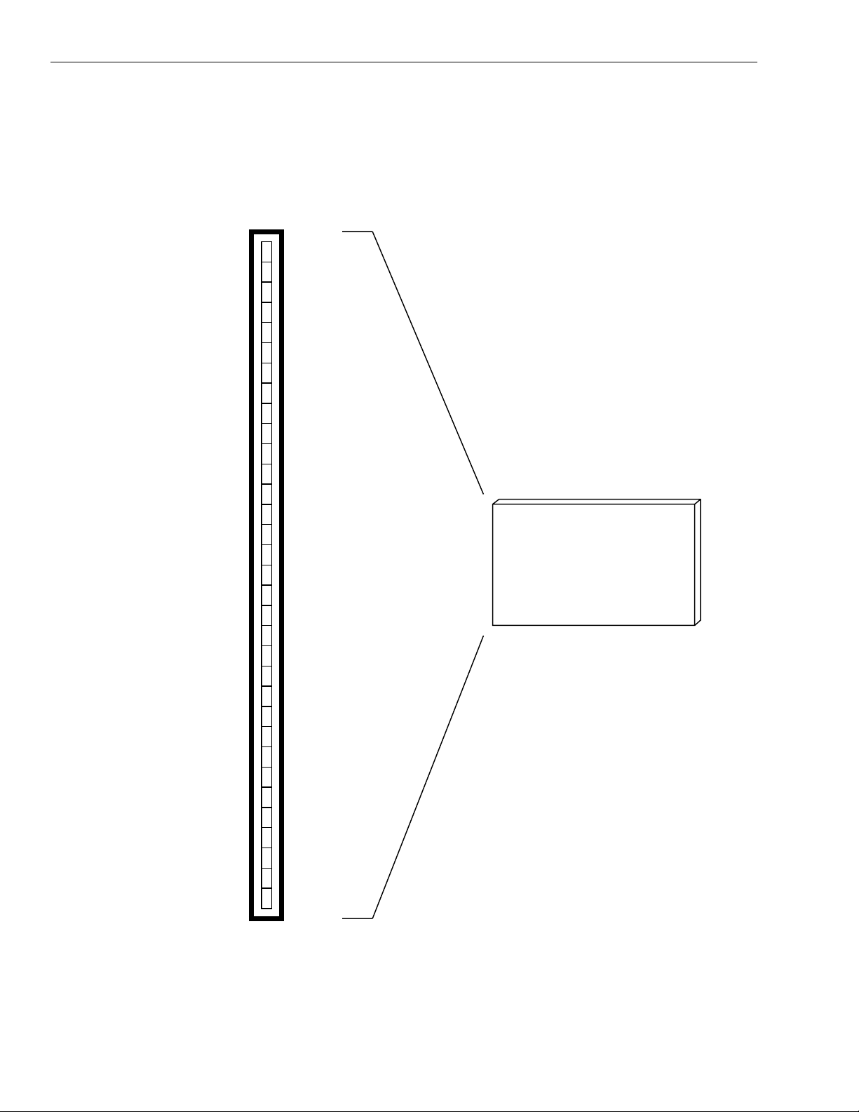
Figure 1-1 shows a complete KPCMCIA-PIO24 system. For applications requiring discrete wire
hook-ups, an optional screw terminal adapter is available to convert the D-37 connector into 37
discrete terminal blocks. Optional accessories are described in Section 7.
Figure 1-1
System configuration
PCMCIA Card
KPCMCIA-PIO24
Cable Assembly
KCAB-PIO
Standard D-37
Page 13

KPCMCIA-PIO24 User’s Manual Introduction 1-3
Technical support
Before returning any equipment for repair, call Keithley Instruments, Inc., for technical
support at:
1-888-KEITHLEY
Monday - Friday, 8:00 a.m. - 5:00 p.m., Eastern Time
An applications engineer will help you diagnose and resolve your problem over the telephone.
If a telephone resolution is not possible, the applications engineer will issue you a Return Material
Authorization (RMA) number and ask you to return the equipment. Include the RMA number
with any documentation regarding the equipment.
When returning equipment for repair, include the following information:
•
Your name, address, and telephone number.
•
The invoice or order number and date of equipment purchase.
A description of the problem or its symptoms.
•
•
The RMA number on the outside of the package.
Repackage the equipment, using the original anti-static wrapping, if possible, and handle it with
ground protection. Ship the equipment to:
ATTN: RMA #_______
Repair Department
Keithley Instruments, Inc.
28775 Aurora Road
Cleveland, Ohio 44139
Telephone 1-888-KEITHLEY
FAX (440) 248-6168
NOTES
If you are submitting your equipment for repair under warranty, you
must include the invoice number and date of purchase.
To enable Keithley Instruments, Inc., to respond as quickly as possible,
you must include the RMA number on the outside of the package.
Page 14

2
Installation
Page 15

2-2 Installation KPCMCIA-PIO24 User’s Manual
Hardware setup
To install a KPCMCIA-PIO24 PC card, insert the adapter into any type II PCMCIA socket. All
other configuration options are determined by the DriverLINX software and operating system, as
discussed in your DriverLINX documentation.
Software setup
Refer to your DriverLINX documentation for a detailed description of the software installation
procedure.
Page 16

3
Theory of Operation
Page 17

3-2 Theory of Operation KPCMCIA-PIO24 User’s Manual
I/O port description
The 24 digital I/O channels that are provided in the KPCMCIA-PIO24 are grouped into three different ports with each port containing eight digital I/O channels. These three ports are controlled
via the data port A control register, data port B control register, and data port C control register.
In each of these three registers, each bit corresponds to one data line. The data port A control
register is used to access data lines DATA7 through DATA0. The data port B control register is
used to access data lines DATA15 through DATA8. The data port C control register is used to
access data lines DATA23 through DATA16.
Each of the 24 I/O channels (DATA23 through DATA0) may be individually programmed for
either input or output. Each data port is latched on a write to that particular port. Each I/O channel
may be programmed for input by writing a 1 to the appropriate bit in the corresponding data port
control register. Each I/O channel is driven by an open-collector driver. Therefore, writing a 1
will turn the open-collector output driver off. When off, the open-collector output driver is tristated. Tri-stating the output driver of an I/O channel allows that I/O channel to be driven by
another device. An I/O channel that is configured for input may be accessed by reading the appropriate data port control register. If a 0 is latched on a particular I/O channel by writing a 0 to the
appropriate bit in the corresponding data port control register, the channel may not be used as
input. The channel will be masked, and a 0 will always be read on the channel.
If an I/O channel is to be used as output, the appropriate data port control register should be written. When a write operation is performed, the data is latched. If a bit is written with a 0, the opencollector output driver will be turned on, and the I/O channel will be driven to a low voltage state.
Writing a 1 to the appropriate bit will turn the open-collector driver off, but a pull-up resistor will
pull the particular I/O channel to a TTL high voltage level.
Upon reset of the KPCMCIA-PIO24, the three data port control registers are all latched with a
value of FFh. This forces all 24 open-collector output drivers off upon a system power-up or a
KPCMCIA-PIO24 card insertion. Thus, all 24 I/O channels are configured as input by default.
Care should be taken prior to programming any of these I/O channels for output. The opencollector drivers should not be turned on (by writing a 0 to the appropriate bit of a data port control
register) if the I/O channel is driven by another device. Driving the channel low by latching a 0
into a bit of the data port control register may cause damage to the peripheral, the host system, or
the KPCMCIA-PIO24 card if the channel is also driven by a peripheral.
Port C interrupts description
The eight port C I/O channels (DATA23 through DATA16) may also be configured as interrupt
sources. If any of these eight I/O channels is to be used to generate an interrupt, the I/O channel
must be configured for input by latching the appropriate bit in the data port C control register to 1.
Also, the interrupt must be enabled by setting the appropriate bit in the port C interrupt enable
register. Eight interrupt sources (INT7 through INT0) may be enabled in this manner. Each of
these interrupt sources corresponds to an I/O channel in port C.
The mode of the port C interrupt sources may be configured in one of four possible manners: level
sensitive active low interrupt, level sensitive active high interrupt, high-to-low transition edge
sensitive interrupt, and low-to-high transition edge sensitive interrupt. The lower nibble (4 bits)
and upper nibble (4 bits) of the port C interrupt sources may be configured separately. This will
allow INT7 through INT4 to be configured for a different mode than INT3 through INT0. These
modes are configured by writing the interrupt mode control register.
Page 18

KPCMCIA-PIO24 User’s Manual Theory of Operation 3-3
Whenever an interrupt is generated due to a port C interrupt source, the corresponding bit of the
interrupt status register is set to reflect the cause of the interrupt. This provides a mechanism for
determining the source of a detected interrupt. The interrupt status register will be continually
updated as additional interrupt generating conditions appear.
Writing a 1 to the appropriate bit of the interrupt acknowledge register is the method by which
interrupts should be acknowledged. After a write to the interrupt acknowledge register, another
interrupt will be generated if the interrupt status register does not contain a value of 00h. Any bit
in the interrupt status register that has a value of 1 can be reset to a value of 0 if the following two
conditions are met: the corresponding bit in the interrupt acknowledge register must be written
with a 1, and the interrupt generating condition must no longer exist. For level sensitive interrupts,
an interrupt will be immediately generated after the write of the interrupt acknowledge register if
the interrupt generating condition (active level on port C interrupt source) remains.
External interrupt description
In addition to the eight port C interrupt sources, an additional external interrupt source is provided
in the KPCMCIA-PIO24. This external interrupt source is accessed through Pin 1 of the external
connector. The external interrupt source permits the KPCMCIA-PIO24 to be operated with 24-bit
input/output and one separate interrupt source.
The interrupt mode control register provides a means of enabling/disabling this external interrupt,
setting the external interrupt mode, reading the status of the external interrupt, and acknowledging the external interrupt. The functionality of this external interrupt source is identical to that
described for the port C interrupt sources in the previous section.
Digital input/output
For applications using the KPCMCIA-PIO24 at output logic control the following information
applies. After insertion into the PCMCIA socket prior to initialization, the 24 digital I/O lines are
set up for input. Therefore, by virtue of the PC Card 10k Ω pull-up resistor, all outputs have a 5V
signal impressed on them. Without a current sink impedance that would pull down the signal,
these digital lines will appear to be TTL Logic ON states to a high impedance interfaces. This is
a consideration for applications that would be adversely affected by the temporary effective ON
state prior to card initialization. See Figure 3-1.
Figure 3-1
Digital input/output diagram
10k
Page 19

4
Register Descriptions
Page 20

4-2 Register Descriptions KPCMCIA-PIO24 User’s Manual
Introduction
The program registers of the KPCMCIA-PIO24 occupy eight contiguous bytes of I/O address
space. These registers must be programmed to control the operation of the KPCMCIA-PIO24.
Table 4-1 lists the program registers along with their offsets relative to the I/O space base address
at which the KPCMCIA-PIO24 is located.
Each KPCMCIA-PIO24 register is discussed in detail in the following paragraphs.
Table 4-1
Program registers
Offset Read/Write Register
0 R/W Data port A control register
1 R/W Data port B control register
2 R/W Data port C control register
5 R/W Port C interrupt enable register
6 R/W Interrupt mode control register
7 R Interrupt status register
7 W Interrupt acknowledge register
Data port A control register (base + 0)
The data port A control register, Table 4-2, contains the control bits for I/O channels DATA0
through DATA7. Each I/O channel may be individually programmed for input by writing a 1 to
the appropriate bit of this register.
Table 4-2
Data port A control register
Bit Name Description
7 DATA7 General purpose I/O bit 7
6 DATA6 General purpose I/O bit 6
5 DATA5 General purpose I/O bit 5
4 DATA4 General purpose I/O bit 4
3 DATA3 General purpose I/O bit 3
2 DATA2 General purpose I/O bit 2
1 DATA1 General purpose I/O bit 1
0 DATA0 General purpose I/O bit 0
Page 21

KPCMCIA-PIO24 User’s Manual Register Descriptions 4-3
Data port B control register (base + 1)
The data port B control register, Table 4-3, contains the control bits for I/O channels DATA8
through DATA15. Each I/O channel may be individually programmed for input by writing a 1 to
the appropriate bit of this register.
Table 4-3
Data port B control register
Bit Name Description
7 DATA15 General purpose I/O bit 15
6 DATA14 General purpose I/O bit 14
5 DATA13 General purpose I/O bit 13
4 DATA12 General purpose I/O bit 12
3 DATA11 General purpose I/O bit 11
2 DATA10 General purpose I/O bit 10
1 DATA9 General purpose I/O bit 9
0 DATA8 General purpose I/O bit 8
Data port C control register (base + 2)
The data port C control register, Table 4-4, contains the control bits for I/O channels DATA16
through DATA23. Each I/O channel may be individually programmed for input by writing a 1 to
the appropriate bit of this register. In addition, any of these eight I/O channels that are programmed
for input may also be used to generate interrupts. In order to program an I/O channel as an interrupt
source, the port C interrupt enable register must be set appropriately. The I/O channel must also
be programmed for input by writing a 1 to the appropriate bit of the data port C control register.
Table 4-4
Data port C control register
Bit Name Description
7 DATA23/INT7 General purpose I/O bit 23 and interrupt line 7
6 DATA22/INT6 General purpose I/O bit 22 and interrupt line 6
5 DATA21/INT5 General purpose I/O bit 21 and interrupt line 5
4 DATA20/INT4 General purpose I/O bit 20 and interrupt line 4
3 DATA19/INT3 General purpose I/O bit 19 and interrupt line 3
2 DATA18/INT2 General purpose I/O bit 18 and interrupt line 2
1 DATA17/INT1 General purpose I/O bit 17 and interrupt line 1
0 DATA16/INT0 General purpose I/O bit 16 and interrupt line 0
Page 22

4-4 Register Descriptions KPCMCIA-PIO24 User’s Manual
Port C interrupt enable register (base + 5)
INT7 through INT0 may be enabled by writing the appropriate bits in the port C interrupt enable
register. The corresponding I/O channel must be configured as an input channel via the data
port C control register if an interrupt is to be generated. If an I/O channel is configured as an interrupt source (INT7 through INT0), the I/O channel continues to be a standard data input channel
(DATA23 through DATA16) and may be read as any other input signal is read. See Table 4-5.
Table 4-5
Port C interrupt control register
Bit Name Description
7 INT7EN 1 = enables INT7; 0 = disables INT7
6 INT6EN 1 = enables INT6; 0 = disables INT6
5 INT5EN 1 = enables INT5; 0 = disables INT5
4 INT4EN 1 = enables INT4; 0 = disables INT4
3 INT3EN 1 = enables INT3; 0 = disables INT3
2 INT2EN 1 = enables INT2; 0 = disables INT2
1 INT2EN 1 = enables INT1; 0 = disables INT1
0 INT1EN 1 = enables INT0; 0 = disables INT0
Page 23

KPCMCIA-PIO24 User’s Manual Register Descriptions 4-5
Interrupt mode control register (base + 6)
The mode of both the external interrupt and the port C interrupts may be controlled with the interrupt mode control register. The upper nibble (4 bits) and lower nibble (4 bits) of the port C interrupts may be configured separately. The external interrupt can also be enabled by writing this
register. The status of the external interrupt can be read in this register, and the external interrupt
can also be acknowledged by writing the appropriate bit in the interrupt mode control register.
See Table 4-6.
Table 4-6
Interrupt mode control register
Bit Name Description
7 ExtIntStat(Read)
ExtIntAck(Write)
6 ExtraIntEn 1 = external interrupt is enabled
5:4 ExtIntControl These two bits control the mode of the external interrupt:
3:2 UpperIntCntrl These two bits control the mode of the upper nibble of
1:0 LowerIntCntrl These two bits control the mode of the lower nibble of
ExtIntStat: to read status of external interrupt
ExtIntAck: write acknowledges external interrupt
0 = external interrupt is disabled
00 = Level sensitive active low interrupt
01 = Level sensitive active high interrupt
10 = High-to-low transition edge sensitive interrupt
11 = Low-to-high transition edge sensitive interrupt
port C (INT7, INT6, INT5, INT4):
00 = Level sensitive active low interrupt
01 = Level sensitive active high interrupt
10 = High-to-low transition edge sensitive interrupt
11 = Low-to-high transition edge sensitive interrupt
port C (INT3, INT2, INT1, INT0):
00 = Level sensitive active low interrupt
01 = Level sensitive active high interrupt
10 = High-to-low transition edge sensitive interrupt
11 = Low-to-high transition edge sensitive interrupt
Page 24

4-6 Register Descriptions KPCMCIA-PIO24 User’s Manual
Interrupt status register (read only, base + 7)
On a read, this register provides the interrupt status for the port C interrupts. This provides a
mechanism for determining the sources of any pending interrupts. A 1 signals that an interrupt
generating condition has occurred on the appropriate channel. Interrupts will continue to occur
until this register has a value of 00h and no interrupt generating conditions remain. This register
must be reset by acknowledging interrupts by writing the interrupt acknowledge register. See
Table 4-7.
Table 4-7
Interrupt status register (read only)
Bit Name Description
7:0 ChanCIntStatus The Status of INT7 - INT0 is read
(Bit 7 = INT7, Bit 6 = INT6, etc...)
Interrupt acknowledge register (write only, base + 7)
Writing a 1 to any bit in the interrupt acknowledge register will acknowledge the interrupt generating condition that was represented in the corresponding bit of the interrupt status register. If a 1
is written to a bit in the interrupt acknowledge register and the corresponding interrupt generating
condition is not present, then the appropriate bit in the interrupt status register will be reset (set
to 0). See Table 4-8.
Table 4-8
Interrupt status register (write only)
Bit Name Description
7:0 ChanCIntAck Written to acknowledge INT 7- INT0
(Bit 7 = INT7, Bit 6 = INT6, etc...)
Page 25

KPCMCIA-PIO24 User’s Manual Register Descriptions 4-7
Summary of interrupt source options
Two interrupt source options are provided in the KPCMCIA-PIO24 and are summarized below:
1. Port C interrupt sources
• The following must be programmed:
— Channel set for input by the data port C control register.
— Interrupt source enabled by the port C interrupt enable register.
— Mode selected by the interrupt mode control register.
• Interrupt generated unless interrupt status register is 00h.
— Interrupt is generated after write of interrupt acknowledge register if any inter-
rupts remain unacknowledged.
— Unacknowledged interrupts are represented by a ‘1’ in the interrupt status
register.
• 1 in interrupt status register is reset to ‘0’ if the following two requirements are satisfied:
— Interrupt acknowledged by writing appropriate bit in interrupt acknowledge
register with ‘1’.
— Condition which caused interrupt is no longer present.
2. External interrupt source
• The following must be programmed:
— Interrupt source enabled by the interrupt mode control register.
— Mode selected by the interrupt mode control register.
• Interrupt generated if ExtIntStat of interrupt mode control register is ‘1’.
• 1 in ExtIntStatus is reset to ‘0’ if the following two requirements are satisfied:
— Interrupt acknowledged by writing ExtIntAck with ‘1’.
— Condition which caused interrupt is no longer present.
Summary of input/output options
Each of the three ports (Port A, Port B, Port C) may be configured in one of three manners:
• Port used as an output
— Write a ‘1’ to the appropriate bits of the latch in order to turn off the output module.
— Write a ‘0’ to the appropriate bits of the latch in order to turn on the output module.
• Port used as an input
— Writing a ‘1’ to all the bits of the latch will allow all the channels of the port to
be read as inputs.
— Writing a ‘0’ to any bits of the latch will mask those bits. Those bits will always be
read as a ‘0’.
• Port used as input and output
If a port is to be used so that some channels are inputs and some channels are outputs, it
must be insured that the channels to be used as inputs are initialized as inputs. This is done
by writing a ‘1’ to the bits of the data port control register representing the I/O channels,
which are to be used as inputs anytime the port is written.
— The channels which are to be inputs should always be written with a 1 and never
written with a ‘0’.
— The channels which are to be outputs should be written with the appropriate value
(0 or 1).
— The channels which are latched with a ‘0’ will always be ‘0’ when read (they
are masked from input).
Page 26

4-8 Register Descriptions KPCMCIA-PIO24 User’s Manual
Programming example
The following C program segment demonstrates how to program a KPCMCIA-PIO24 located at
I/O base address 300h. Port A will be programmed as output, and 55h will be latched at port A.
Port B will be configured with its upper 3 bits as output and its lower five bits as input. The upper
three bits will be latched with 010b. Port C will be configured as input. Interrupts will be enabled
as explained in the program comments.
outp(0x300,0x55); /* writes 55h to port A */
outp(0x301,0x5F); /* writes 010b to port B upper 3 bits */
/* sets port B lower 5 bits for input */
outp(0x302,0xFF); /* initializes port C for input */
Port_B = inp(0x301); /* reads data from port B */
/* Port_B(bit7) = '0' and Port_B(bit5) = '0' due to 'masking' */
Port_C = inp(0x302); /* reads data from port C */
outp(0x306,0x76);
/* INT7 - INT4 set for level sensitive active high interrupt mode */
/* INT3 - INT0 set for edge sensitive high-to-low transition interrupt source */
/* External interrupt source enabled */
/* External interrupt source set for low-to-high edge sensitive interrupt source */
outp(0x305,0x77);
/* Enables six port C interrupt sources */
/* Enables INT6,INT5,INT4,INT2,INT1,INT0 */
Page 27

5
External Connections
Page 28
5-2 External Connections KPCMCIA-PIO24 User’s Manual
PCMCIA 33-pin connector
The KPCMCIA-PIO24 is fitted with a 33-pin 0.8mm shielded connector with the pins assigned
as shown in Figure 5-1.
Figure 5-1
PCMCIA 33-pin connector
10
15
20
25
30
33
1
5
GND
DATA 0
DATA 1
DATA 2
DATA 3
DATA 4
DATA 5
DATA 6
DATA 7
GND
DATA 8
DATA 9
DATA10
DATA11
DATA12
DATA13
DATA14
DATA15
GND
DATA16/INT0
DATA17/INT1
DATA18/INT2
DATA19/INT3
DATA20/INT4
DATA21/INT5
DATA22/INT6
DATA23/INT7
GND
EXT_IRQ
GND
GND
GND
GND
KPCMCIA-PIO24
Page 29

KPCMCIA-PIO24 User’s Manual External Connections 5-3
KCAB-PIO cable assembly
Keithley part number KCAB-PIO, converts the KPCMCIA-PIO24’s 33-pin 0.8mm I/O connector
to a standard D-37 male connector. See Figure 5-2.
Figure 5-2
KPCMCIA-PIO24 output connections using the optional KCAB-PIO.
GND
N/C
N/C
N/C
GND
N/C
GND
N/C
GND
DATA 8
DATA 9
DATA10
DATA11
DATA12
DATA13
DATA14
DATA15
N/C
EXT_IRQ
19
18
17
16
15
14
13
12
11
10
37
DATA 0
DATA 1
36
DATA 2
35
DATA 3
34
DATA 4
33
DATA 5
32
DATA 6
31
DATA 7
30
DATA16/INT0
29
DATA17/INT1
28
9
DATA18/INT2
27
8
25
24
23
22
21
20
DATA19/INT3
DATA20/INT4
DATA21/INT5
DATA22/INT6
DATA23/INT7
GND
N/C
26
7
6
5
4
3
2
1
Page 30

6
Cabling and Wiring
Page 31
6-2 Cabling and Wiring KPCMCIA-PIO24 User’s Manual
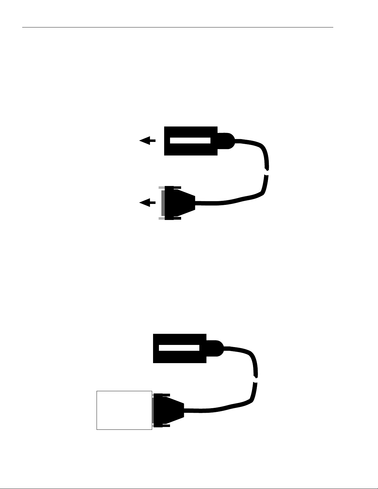
Introduction
This section describes how to wire accessories and signals to your KPCMCIA-PIO24. The
KPCMCIA-PIO24 and I/O cable appear as shown in Figure 6-1.
The main I/O connector of the KPCMCIA-PIO24 cable is a female, 37-pin, D type. Pin assignments for this connector are shown in Figure 5-2.
Figure 6-1
KPCMCIA-PIO24 and attached I/O cable
To PCMCIA
socket in
desktop or
notebook
computer
KPCMCIA-PIO24
37-pin main I/O
connector on
KPCMCIA-PIO24
cable to
accessories
Connecting an SSIO-24, ERB-24, ERA-01, or SRA-01
The following accessories attach directly to the I/O cable of a KPCMCIA-PIO24, as shown in
Figure 6-2: SSIO-24, ERB-24, ERA-01, and SRA-01.
NOTE
Figure 6-2
Attaching an SSIO-24, ERB-24, ERA-01, or SRA-01 to a KPCMCIA-PIO24 cable
Each of these accessories requires external power when connected to
a KPCMCIA-PIO24. To ensure correct power connections, be sure to
refer to the user manuals for these accessories.
KPCMCIA-PIO24
SSIO-24, ERB-24,
ERA-01, or
SRA-01
Page 32
KPCMCIA-PIO24 User’s Manual Cabling and Wiring 6-3
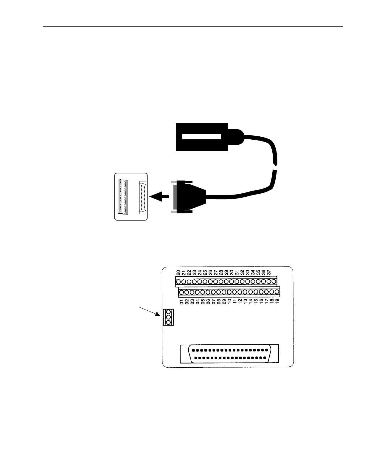
Connecting an STP-37 or STA-U
The STP-37 and STA-U are screw-terminal panels that attach to the main I/O connector of a
KPCMCIA-PIO24 cable, as shown in Figure 6-3. The STP-37/C is the STP-37 with a protective
bottom cover. While Figure 6-3 shows a STP-37 or STP-37/C, the STA-U attaches to the
KPCMCIA-PIO24 cable in exactly the same manner. The STP-37 and STP-37/C appear as shown
in Figure 6-4.
Figure 6-3
Connecting an STP-37 or STP-37/C to a KPCMCIA-PIO24
KPCMCIA-PIO24
STP-37
or
STP-37/C
Figure 6-4
Panel layout of STP-37 and STP-37/C
Note:
Screw terminals
for CJC are not
used with
KPCMCIA-PIO24
Page 33

6-4 Cabling and Wiring KPCMCIA-PIO24 User’s Manual
Connecting special-purpose I/O circuits
The following paragraphs describe commonly used circuits for the inputs or outputs of a
KPCMCIA-PIO24.
Connecting a contact-closure monitor to an input
Figure 6-5 shows a circuit for monitoring contact closure at a KPCMCIA-PIO24 input.
Figure 6-5
Contact-closure monitor for a KPCMCIA-PIO24 input
KPCMCIA-PIO24
NOTE The circuit in Figure 6-5 does not contain a debounce circuit. De-
bounce can be handled by your application program or by the circuit
described in the following paragraphs.
Connecting an input to a debounce circuit
Since debounce can be handled by your application program, Figure 6-6 shows a debounce circuit
you can use at an input of a KPCMCIA-PIO24.
Figure 6-6
Debounce circuit for a KPCMCIA-PIO24 input
To Digital Input
of
KPCMCIA-PIO24
Page 34

KPCMCIA-PIO24 User’s Manual Cabling and Wiring 6-5
Connecting an output to Darlington NPN for relay control
You can achieve relay control at an output of a KPCMCIA-PIO24 using a Darlington NPN transistor, as shown in Figure 6-7.
Figure 6-7
Darlington NPN relay control for an output of a KPCMCIA-PIO24
KPCMCIA-PIO24
Page 35

7
Optional Accessories
Page 36

7-2 Optional Accessories KPCMCIA-PIO24 User’s Manual
The following accessories are also available for use with your KPCMCIA-PIO24:
SSIO-24 — is a 24-channel mounting panel for up to 24 solid-state, miniature I/O modules with
functions of DC input, DC output, AC input, and AC output. The SSIO-24 connects to the main
I/O connector of the KPCMCIA-PIO24 cable. It requires external power (+5VDC) when used
with the KPCMCIA-PIO24.
ERB-24 — is a relay board that provides 24 electromechanical double-pole, double-throw relays
for controlling and switching up to 3A and 120V
. The ERB-24 connects to the main I/O con-
rms
nector of the KPCMCIA-PIO24 cable. It has a built-in power supply requiring 115/230VAC.
ERA-01 — is an electrical relay board containing eight single-pole, double-throw relays that can
switch up to 3A at 120V
. The ERA-01 requires external power (+5VDC) when used with the
rms
KPCMCIA-PIO24.
SRA-01 — is an 8-channel, solid-state, mounting panel for industry-standard I/O modules used
in sensing and controlling AC and DC circuits. The SRA-01 requires external power (+5VDC)
when used with the KPCMCIA-PIO24.
STP-37 — is a screw-terminal panel for general-purpose connections in a compact form factor.
STA-U — is a universal screw-terminal accessory that connects to the main I/O connector of the
KPCMCIA-PIO24 to bring the card’s I/O signals to convenient screw terminals.
Refer to the Keithley catalog or contact your local sales office for information on obtaining these
accessories.
Page 37

A
Specifications
Page 38

A-2 Specifications KPCMCIA-PIO24 User’s Manual
Bus interface
PCMCIA
PC card standard 2.1 compliant
Physical dimensions
Power requirements
Type II PCMCIA card (5mm)
+5 volts
7.33mA typical (all outputs off)
12.38mA maximum (all outputs off)
36.38mA maximum (all outputs on)
Digital input/output
Current source/sink
TTL Compatible
Sink 6mA (min) at 0.33V
(at 25˚C) Sink 20mA (min) at 1.0V
Source 1.1mA max into 0 Ω at V
Input/output current
Connector
25mA maximum
Adapter to standard male D-37
CC
=5V
Page 39

Index
C
Cabling and wiring 6-1
Connecting a contact-closure monitor to an input 6-4
Connecting an input to a debounce circuit 6-4
Connecting an output to Darlington NPN for relay
control 6-5
Connecting an SSIO-24, ERB-24, ERA-01, or
SRA-01 6-2
Connecting an STP-37 or STA-U 6-3
Connecting special-purpose I/O circuits 6-4
D
Data port A control register (base + 0) 4-2
Data port B control register (base + 1) 4-3
Data port C control register (base + 2) 4-3
Digital input/output 3-3
E
External connections 5-1
External interrupt description 3-3
F
Features 1-2
H
Hardware setup 2-2
K
KCAB-PIO cable assembly 5-3
O
Optional accessories 7-1
P
PCMCIA 33-pin connector 5-2
Port C interrupt enable register (base + 5) 4-4
Port C interrupts description 3-2
Programming example 4-8
R
Register descriptions 4-1
S
Software setup 2-2
Specifications A-1
Summary of input/output options 4-7
Summary of interrupt source options 4-7
System configuration 1-2
T
Technical support 1-3
Theory of operation 3-1
I
Installation 2-1
Introduction 1-1, 4-2, 6-2
I/O port description 3-2
Interrupt acknowledge register (write only, base + 7) 4-6
Interrupt mode control register (base + 6) 4-5
Interrupt status register (read only, base + 7) 4-6
i-1
Page 40

Specifications are subject to change without notice.
All Keithley trademarks and trade names are the property of Keithley Instruments, Inc. All other
trademarks and trade names are the property of their respective companies.
Keithley Instruments, Inc. 28775 Aurora Road • Cleveland, Ohio 44139 • 440-248-0400 • Fax: 440-248-6168
1-888-KEITHLEY (534-8453) • www.keithley.com
Sales Offices: BELGIUM: Bergensesteenweg 709 • B-1600 Sint-Pieters-Leeuw • 02-363 00 40 • Fax: 02/363 00 64
CHINA: Yuan Chen Xin Building, Room 705 • 12 Yumin Road, Dewai, Madian • Beijing 100029 • 8610-6202-2886 • Fax: 8610-6202-2892
FINLAND: Tietäjäntie 2 • 02130 Espoo • Phone: 09-54 75 08 10 • Fax: 09-25 10 51 00
FRANCE: 3, allée des Garays • 91127 Palaiseau Cédex • 01-64 53 20 20 • Fax: 01-60 11 77 26
GERMANY: Landsberger Strasse 65 • 82110 Germering • 089/84 93 07-40 • Fax: 089/84 93 07-34
GREAT BRITAIN: Unit 2 Commerce Park, Brunel Road • Theale • Berkshire RG7 4AB • 0118 929 7500 • Fax: 0118 929 7519
INDIA: Flat 2B, Willocrissa • 14, Rest House Crescent • Bangalore 560 001 • 91-80-509-1320/21 • Fax: 91-80-509-1322
ITALY: Viale San Gimignano, 38 • 20146 Milano • 02-48 39 16 01 • Fax: 02-48 30 22 74
JAPAN: New Pier Takeshiba North Tower 13F • 11-1, Kaigan 1-chome • Minato-ku, Tokyo 105-0022 • 81-3-5733-7555 • Fax: 81-3-5733-7556
KOREA: 2FL., URI Building • 2-14 Yangjae-Dong • Seocho-Gu, Seoul 137-888 • 82-2-574-7778 • Fax: 82-2-574-7838
NETHERLANDS: Postbus 559 • 4200 AN Gorinchem • 0183-635333 • Fax: 0183-630821
SWEDEN: c/o Regus Business Centre • Frosundaviks Allé 15, 4tr • 169 70 Solna • 08-509 04 679 • Fax: 08-655 26 10
SWITZERLAND: Kriesbachstrasse 4 • 8600 Dübendorf • 01-821 94 44 • Fax: 01-820 30 81
TAIWAN: 1FL., 85 Po Ai Street • Hsinchu, Taiwan, R.O.C. • 886-3-572-9077• Fax: 886-3-572-9031
© Copyright 2001 Keithley Instruments, Inc.
Printed in the U.S.A.
4/02
 Loading...