

Page 1

VIEWDAC
WHAT'S NEW IN VERSION 2.2
Page 2
New Contact Information
Keithley Instruments, Inc.
28775 Aurora Road
Cleveland, OH 44139
Technical Support: 1-888-KEITHLEY
Monday – Friday 8:00 a.m. to 5:00 p.m (EST)
Fax: (440) 248-6168
Visit our website at http://www.keithley.com
Page 3

The information contained in this manual is believed to be accurate and reliable. However, Keithley
Instruments, Inc., assumes no responsibility for its use or for any infringements of patents or other rights
of third parties that may result from its use. No license is granted by implication or otherwise under any
patent rights of Keithley Instruments, Inc.
KEITHLEY INSTRUMENTS, INC., SHALL NO T BE LIABLE FOR ANY SPECIAL, INCIDENT AL,
OR CONSEQUENTIAL DAMAGES RELATED TO THE USE OF THIS PRODUCT. THIS
PRODUCT IS NOT DESIGNED WITH COMPONENTS OF A LEVEL OF RELIABILITY SUITED
FOR USE IN LIFE SUPPORT OR CRITICAL APPLICATIONS.
Refer to your Keithley Instruments license agreement and Conditions of Sale document for specific
warranty and liability information.
VIEWDA C is a registered trademark of K eithle y Instruments, Inc. MetraByte is a trademark of Keithle y
Instruments, Inc. All other brand and product names are trademarks or registered trademarks of their
respective companies.
© Copyright Keithley Instruments, Inc., 1994.
All rights reserved. Reproduction or adaptation of any part of this documentation beyond that permitted
by Section 117 of the 1976 United States Copyright Act without permission of the Copyright owner is
unlawful.
Keithley MetraByte Division
Keithley Instruments, Inc.
440 Myles Standish Blvd. Taunton, MA 02780
Telephone: (508) 880-3000
Revision A - April 1994
Part Number: 53206
FAX: (508) 880-0179
●
Page 4

Preface
VIEWDAC - What’s New in Version 2.2 provides information about new
features in VIEWDAC 2.2, information about compatibility issues you
should keep in mind when upgrading from VIEWDAC 2.1 to
VIEWDA C 2.2, and information that was either missing from or incorrect
in the VIEWDAC Reference manual.
The document is intended for VIEWDAC application programmers who
are either new users of VIEWDAC or users upgrading from
VIEWDAC 2.1.
It is assumed that you are familiar with data acquisition principles, with
your particular application, with the computer you are using, and with the
features in VIEWDAC 2.1. It is also assumed that you are familiar with
standard windowing-type environments, including the use of a mouse, a
keyboard, pull-down and pop-up menus, dialog boxes, and the clipboard.
Refer to VIEWDAC - Getting Started for information about how the
windowing-type environment is used in VIEWDAC.
Wherever possible, this document uses the same format and terminology
as the VIEWDA C Reference manual. You should be familiar with both the
VIEWDA C Refer ence manual and VIEWDA C - Getting Started before you
read this document.
Overview of Contents
VIEWDAC - What’s New in Version 2.2 is organized as follows:
Overview of New Features provides a brief overview of the new
●
features in VIEWDAC 2.2.
vii
Page 5

Compatibility with VIEWDAC 2.1 provides information to keep in
●
mind when upgrading from VIEWDAC 2.1 to VIEWDAC 2.2.
●
New Features provides detailed information about the new features
in VIEWDA C 2.2.
Software Enhancements describes software enhancements that are
●
provided in VIEWDAC 2.2.
●
Errata provides information that was either missing from or
incorrect in the VIEWDAC Reference manual.
An index completes this document.
Documentation Conventions
Keep the following conventions in mind as you use this document:
Information that you must type is shown in
●
example, to load the demonstration driver, enter
courier
typeface. For
DASDEMO
at the DOS
prompt. Unless otherwise specified, you can type characters in either
UPPERCASE or lowercase.
●
Variable information is shown in italics . For example, filename.ext
denotes that you should supply an appropriate file name and
extension.
●
Keyboard keys are denoted by square brackets surrounding the key's
label. For example, [Esc] is the escape key, [Del] is the delete key,
[F2] is the F2 function key, and so on.
If two keys are joined by a plus symbol, you should hold down the
●
first key while you press the second key. For example, [Ctrl]+[Break]
denotes that you should hold down [Ctrl] while you press [Break].
●
If two keys are separated by a space, you should press the keys
sequentially. For example, [F] [spacebar] denotes that you should
press and release [F] and then press and release [spacebar].
viii
●
A specific arrow key is denoted by the direction in which its arrow
points: [up arrow], [down arrow], [right arrow], and [left arrow].
Page 6

The term "enter" indicates that you should press the specified key or
●
type the specified characters and then press [Enter] or [Return].
●
The terms "press" and "type" indicate that you should press the
specified key or type the specified characters without pressing
[Enter].
The term "click" indicates that you should either highlight an item or
●
initiate an action using the mouse. For example, to click on the OK
push button, move the mouse pointer to the OK push button and then
press the left mouse button.
The term "select" indicates that you should either highlight an item or
●
initiate an action using either the mouse or the keyboard. For
example, you can select the OK push button in a dialog box either by
clicking on OK or by using [Tab] to move to the OK push button and
then pressing [spacebar].
●
The term "menu" refers to pull-down menus. Pop-up menus are
always referred to as pop-up menus.
●
The forward slash (/) indicates an either/or selection. For example,
ON/OFF means the result is either on or off, but not both.
●
The back slash (\) denotes a sequence of menu selections. For
example, File\New\Text Edit denotes that you should first select the
File option from the menu bar, then select the New option from the
File menu, and then select the Text Edit option from the New menu.
ix
Page 7

Related Documentation
Refer to the following documentation for more information about using
VIEWDAC:
VIEWDA C - Getting Started - This manual provides procedures for
●
installing and running VIEWDAC in your computer, an overview of
the navigational tools used to get around in the VIEWDAC
environment, an overview of VIEWDAC features, and information
about using the VIEWRUN run-time system.
Note:
VIEWDAC - Getting Started replaces the following
documents: VIEWDAC Roadmap , VIEWDAC Environment , Encore -
a quick reference to VIEWDAC , and VIEWRUN - The VIEWDAC
Run-Time System .
VIEWDA C Tutorials - This manual provides tutorials for using
●
VIEWDAC. Read this manual when you feel comfortable with
VIEWDAC's visual interface and are ready to begin learning to use
VIEWDAC's sequences. The first two chapters introduce sequences,
which are groups of tasks or actions; the remaining chapters provide
specialized information, including graphics, data processing,
interactive data analysis, curve fitting, and using macros.
●
VIEWDAC Reference - This manual includes definitions of
VIEWDAC concepts, descriptions of all features prior to
VIEWDAC 2.2, a glossary, and a comprehensive index. Use the
individual task category chapters to decide which tasks to choose and
how to set them up.
●
Read Me First brochure - This brochure contains warranty
information, a registration card, customer support information, and
the package serial number.
x
Page 8

Documentation on disk - The following files are provided on disk:
●
– README.1ST - Includes last-minute VIEWDAC information.
– DEVICES.DOC - Contains a complete list of supported graphics
adapters.
– DEMOS.DOC - Describes the demonstration sequences
provided with VIEWDAC.
– BDE.DOC - Contains additional printer configuration
information.
– FILES.DOC - Contains a brief description of all files provided
with the VIEWDAC software package.
xi
Page 9

Table of Contents
Preface
Overview of Contents. . . . . . . . . . . . . . . . . . . . . . . . . . . . . . . . . . vii
Documentation Conventions . . . . . . . . . . . . . . . . . . . . . . . . . . . .viii
Related Documentation . . . . . . . . . . . . . . . . . . . . . . . . . . . . . . . . . x
Overview of New Features
Compatibility with VIEWDAC 2.1
Configuration Files. . . . . . . . . . . . . . . . . . . . . . . . . . . . . . . . . . . . . 3
Binary Sequences. . . . . . . . . . . . . . . . . . . . . . . . . . . . . . . . . . . . . . 4
Converting Binary Sequences to ASCII Sequences . . . . . . . . . 4
Converting ASCII Sequences to Binary Sequences . . . . . . . . . 5
Macros . . . . . . . . . . . . . . . . . . . . . . . . . . . . . . . . . . . . . . . . . . . . . . 5
New Features
Printing. . . . . . . . . . . . . . . . . . . . . . . . . . . . . . . . . . . . . . . . . . . . . . 7
Printer Support . . . . . . . . . . . . . . . . . . . . . . . . . . . . . . . . . . . . . 7
Printer Location. . . . . . . . . . . . . . . . . . . . . . . . . . . . . . . . . . . . . 7
Printer Resolution . . . . . . . . . . . . . . . . . . . . . . . . . . . . . . . . . . . 9
Color Printing . . . . . . . . . . . . . . . . . . . . . . . . . . . . . . . . . . . . . . 9
White on Black/Black on White . . . . . . . . . . . . . . . . . . . . . . . 13
Using Data Sets . . . . . . . . . . . . . . . . . . . . . . . . . . . . . . . . . . . . . . 14
Types of Data Sets. . . . . . . . . . . . . . . . . . . . . . . . . . . . . . . . . . 15
Specifying a Data Set Option . . . . . . . . . . . . . . . . . . . . . . . . . 16
Data Set Options . . . . . . . . . . . . . . . . . . . . . . . . . . . . . . . . . . . 18
Control Help Function . . . . . . . . . . . . . . . . . . . . . . . . . . . . . . . . . 20
Setting Up Control Relationships . . . . . . . . . . . . . . . . . . . . . . 21
Describing Control Relationships . . . . . . . . . . . . . . . . . . . . . . 23
The Call Task . . . . . . . . . . . . . . . . . . . . . . . . . . . . . . . . . . . . . . . . 24
Differences Between Using a Call Task and a Control List . . 25
Finding Sequences Required by the Call Task . . . . . . . . . . . . 27
Adding a Call Task . . . . . . . . . . . . . . . . . . . . . . . . . . . . . . . . . 28
Using Call Tasks with Library Sequences. . . . . . . . . . . . . . . . 30
The Array Display Task . . . . . . . . . . . . . . . . . . . . . . . . . . . . . . . . 31
Adding an Array Display Task . . . . . . . . . . . . . . . . . . . . . . . . 32
Setting the Style of the Array Display. . . . . . . . . . . . . . . . . . . 34
iii
Page 10

Software Enhancements
Window Support . . . . . . . . . . . . . . . . . . . . . . . . . . . . . . . . . . . . . 41
Scrolling. . . . . . . . . . . . . . . . . . . . . . . . . . . . . . . . . . . . . . . . . . . . 41
Removing Data Sets. . . . . . . . . . . . . . . . . . . . . . . . . . . . . . . . . . . 42
Manipulating Tasks . . . . . . . . . . . . . . . . . . . . . . . . . . . . . . . . . . . 43
Modal Front Panels . . . . . . . . . . . . . . . . . . . . . . . . . . . . . . . . . . . 44
Snap-to-Grid Option . . . . . . . . . . . . . . . . . . . . . . . . . . . . . . . . . . 45
PCX Files. . . . . . . . . . . . . . . . . . . . . . . . . . . . . . . . . . . . . . . . . . . 46
Types of PCX Files Supported . . . . . . . . . . . . . . . . . . . . . . . . 46
Number of PCX Files Supported . . . . . . . . . . . . . . . . . . . . . . 46
Strip Chart Task . . . . . . . . . . . . . . . . . . . . . . . . . . . . . . . . . . . . . . 47
D to A Task. . . . . . . . . . . . . . . . . . . . . . . . . . . . . . . . . . . . . . . . . . 48
Event Counting Task . . . . . . . . . . . . . . . . . . . . . . . . . . . . . . . . . . 49
Errata
Entering Numbers . . . . . . . . . . . . . . . . . . . . . . . . . . . . . . . . . . . . 51
String Data Sets . . . . . . . . . . . . . . . . . . . . . . . . . . . . . . . . . . . . . . 52
Array Space . . . . . . . . . . . . . . . . . . . . . . . . . . . . . . . . . . . . . . . . . 52
Color Mapping. . . . . . . . . . . . . . . . . . . . . . . . . . . . . . . . . . . . . . . 52
Saving Binary Sequences. . . . . . . . . . . . . . . . . . . . . . . . . . . . . . . 53
Using PCX Files in Front Panels . . . . . . . . . . . . . . . . . . . . . . . . . 53
Hide/Show Task . . . . . . . . . . . . . . . . . . . . . . . . . . . . . . . . . . . . . . 54
Absolute Time Trigger Task. . . . . . . . . . . . . . . . . . . . . . . . . . . . . 54
Threshold Task. . . . . . . . . . . . . . . . . . . . . . . . . . . . . . . . . . . . . . . 55
Calc Tasks . . . . . . . . . . . . . . . . . . . . . . . . . . . . . . . . . . . . . . . . . . 56
Numeric Operation Task . . . . . . . . . . . . . . . . . . . . . . . . . . . . . . . 56
Array Operation Task. . . . . . . . . . . . . . . . . . . . . . . . . . . . . . . . . . 56
String Operation Task. . . . . . . . . . . . . . . . . . . . . . . . . . . . . . . . . . 57
Data I/O Tasks . . . . . . . . . . . . . . . . . . . . . . . . . . . . . . . . . . . . . . . 57
DAS Tasks . . . . . . . . . . . . . . . . . . . . . . . . . . . . . . . . . . . . . . . . . . 58
A to D Task . . . . . . . . . . . . . . . . . . . . . . . . . . . . . . . . . . . . . . . . . 58
Thermocouple Task . . . . . . . . . . . . . . . . . . . . . . . . . . . . . . . . . . . 59
Counter/Timer Tasks . . . . . . . . . . . . . . . . . . . . . . . . . . . . . . . . . . 60
Pulse Output Task. . . . . . . . . . . . . . . . . . . . . . . . . . . . . . . . . . . . . 61
Graphics . . . . . . . . . . . . . . . . . . . . . . . . . . . . . . . . . . . . . . . . . . . . 62
Table Editor . . . . . . . . . . . . . . . . . . . . . . . . . . . . . . . . . . . . . . . . . 62
Using an X Data Set in Analysis Operations. . . . . . . . . . . . . . . . 63
Rounding Numbers in Analysis Operations. . . . . . . . . . . . . . . . . 63
Macros . . . . . . . . . . . . . . . . . . . . . . . . . . . . . . . . . . . . . . . . . . . . . 64
New Initialization File Commands . . . . . . . . . . . . . . . . . . . . . . . 64
Initialization File Command Example. . . . . . . . . . . . . . . . . . . . . 66
Using Pre-emption . . . . . . . . . . . . . . . . . . . . . . . . . . . . . . . . . . . . 66
iv
Page 11

Interpreting Numeric Literals. . . . . . . . . . . . . . . . . . . . . . . . . . . . 66
Watcom C Compiler. . . . . . . . . . . . . . . . . . . . . . . . . . . . . . . . . . . 67
Task Scheduling . . . . . . . . . . . . . . . . . . . . . . . . . . . . . . . . . . . . . . 67
Index
List of Figures
Figure 1. Hardcopy Configuration Dialog Box. . . . . . . . . . . . 8
Figure 2. Elements of the printer.palette Data Set . . . . . . . . 10
Figure 3. Sequence Configuration Dialog Box. . . . . . . . . . . 17
Figure 4. Data Set Name Conflict Dialog Box . . . . . . . . . . . 18
Figure 5. Control Dialog Box . . . . . . . . . . . . . . . . . . . . . . . . 21
Figure 6. Using a Control List. . . . . . . . . . . . . . . . . . . . . . . . 25
Figure 7. Using a Call Task. . . . . . . . . . . . . . . . . . . . . . . . . . 26
Figure 8. Call Task Dialog Box . . . . . . . . . . . . . . . . . . . . . . 28
Figure 9. Array Display in Front Panel. . . . . . . . . . . . . . . . . 31
Figure 10. Array Display Task Dialog Box . . . . . . . . . . . . . . 33
Figure 11. Array Display Style Dialog Box . . . . . . . . . . . . . . 35
Figure 12. Strip Chart Style Dialog Box. . . . . . . . . . . . . . . . . 47
Figure 13. Scan Rate . . . . . . . . . . . . . . . . . . . . . . . . . . . . . . . . 59
Figure 14. Sample Rate. . . . . . . . . . . . . . . . . . . . . . . . . . . . . . 60
Figure 15. Continuous Pulse Mode. . . . . . . . . . . . . . . . . . . . . 61
Figure 16. One-Shot Pulse Mode . . . . . . . . . . . . . . . . . . . . . . 62
List of Tables
Table 1. Elements of the printer.palette Data Set . . . . . . . . 11
Table 2. Action Performed when VIEWDAC Encounters a
Data Set with the Same Name . . . . . . . . . . . . . . . 20
Table 3. Names of Pasted and Duplicated Tasks. . . . . . . . . 44
Table 4. Number Bases . . . . . . . . . . . . . . . . . . . . . . . . . . . . 51
Table 5. New Initialization File Commands . . . . . . . . . . . . 65
Table 6. Where Data I/O Tasks are Performed . . . . . . . . . . 68
v
Page 12

Overview of
New Features
VIEWDAC 2.2 provides the following new features:
●
Enhanced printing options - Many new printers, including several
color printers, are now supported. Screen colors are simulated more
closely in the printed image. You can select a printer resolution mode
to determine the size and level of detail of your printed image. Refer
to page 7 for more detailed information about the new printing
features.
Options when using data sets - You can select one of several data set
●
options that allow you to either reuse existing data sets in the system
or create new data sets when loading sequences. Refer to
page 14 for more detailed information about using data sets.
The new Control Help function - A Control Help box has been
●
added to the Control dialog box. The Control Help box helps you to
set up the control list for each task by allowing you to create an
English-like sentence that describes the control relationships. Refer to
page 20 for more detailed information about the Control Help
function.
The new Call task - The Call task is a new System task that is similar
●
to a subroutine in programming. The Call task allows you to use the
same set of tasks more than once in your VIEWDAC application.
Refer to page 24 for more detailed information about the Call task.
●
The new Array Display task - The Array Display task is a ne w Panel
task that allows you to display the current values of a numeric or
string array in an array display in a front panel. Refer to page 31 for
more detailed information about the Array Display task.
1
Page 13

Note:
In addition to these new features, many minor software
enhancements are provided in VIEWDAC 2.2. Refer to page 41 for
information about these software enhancements.
2 Overview of New Features
Page 14

This section contains compatibility issues to keep in mind when
upgrading from VIEWDAC 2.1 to VIEWDAC 2.2.
Configuration Files
Compatibility with
VIEWDAC 2.1
Configuration files created for VIEWDAC 2.1 are not compatible with
VIEWDAC 2.2. When you change configuration options in VIEWDAC
2.2 and select System\Save Options, the configuration options are saved
to a configuration file compatible with VIEWDAC 2.2; this file is called
VIEWDAC.CFG if you do not specify otherwise.
Note:
maintain both VIEWDAC 2.1 and VIEWDAC 2.2 initially. If you cannot
maintain both versions and must install VIEWDAC 2.2 in the directory
that contains your VIEWDAC 2.1 files, make sure that you delete your
old configuration files.
Refer to VIEWDAC - Getting Started for more information about
configuration files.
If you have sufficient hard disk space, it is recommended that you
3
Page 15

Binary Sequences
VIEWDAC 2.2 will not open binary sequences (.BEQ) created with
VIEWDA C 2.1. If you want to use your VIEWD A C 2.1 binary sequences,
you must convert them to ASCII sequences (.SEQ) before using them in
VIEWDAC 2.2. Then, after you load VIEWDAC 2.2, you can convert the
VIEWDAC 2.1 ASCII sequences to VIEWDAC 2.2 binary sequences.
Refer to the following sections for more information.
Converting Binary Sequences to ASCII Sequences
To convert a VIEWDAC 2.1 binary sequence to a VIEWDAC 2.1 ASCII
sequence, perform the following steps:
1. Make a backup copy of all your VIEWDAC 2.1 sequences.
2. Start up VIEWDAC 2.1.
3. Select File\Open\Sequence to load the binary sequence you want to
convert.
4. Select File\Save As... and select the ASCII radio button in the File
Save As for Sequence dialog box to save the binary sequence as an
ASCII sequence.
Notes:
from BEQ to SEQ so that you can distinguish between the binary
sequence and the ASCII sequence.
Only scalar data (not array data) is saved with the ASCII sequence.
It is recommended that you change the sequence extension
4 Compatibility with VIEWDAC 2.1
Page 16

Converting ASCII Sequences to Binary Sequences
To convert a VIEWDAC 2.1 ASCII sequence to a VIEWDAC 2.2 binary
sequence, perform the following steps:
1. Install VIEWDAC 2.2; refer to VIEWDAC - Getting Started for
information.
Macros
Note:
you maintain both VIEWD AC 2.1 and VIEWD A C 2.2 initially. If you
do, you can access your VIEWDAC 2.1 binary sequences at a later
time, if necessary.
2. Start up VIEWDAC 2.2.
3. Select File\Open\Sequence and load the ASCII sequence.
4. Select File\Save As... and select the Binary radio button in the File
Save As for Sequence dialog box to save the ASCII sequence as a
binary sequence.
Note:
from SEQ to BEQ so that you can distinguish between the ASCII
sequence and the binary sequence.
If you have sufficient hard disk space, it is recommended that
It is recommended that you change the sequence extension
You can load macros created in VIEWDAC 2.1 into VIEWDAC 2.2.
However, because the dialog boxes associated with the VIEWDAC 2.2
features may differ in screen position and size from the dialog boxes in
VIEWDAC 2.1, the macros may not perform in the same way . Therefore,
it is recommended that you do not reuse any macros created in
VIEWDAC 2.1.
5
Page 17

6 Compatibility with VIEWDAC 2.1 7
Page 18

Printing
New Features
This section contains detailed information about the new features in
VIEWDAC 2.2.
The following subsections describe changes to the way screen images are
printed in VIEWDAC 2.2.
Printer Support
VIEWDA C 2.2 supports man y additional printers, including se veral color
printers. The Hardcopy Configuration dialog box contains a list of all
supported printers. Select System\Hardcopy Config... to display the list.
In VIEWDAC 2.2, the list of printers in the Hardcopy Configuration
dialog box is shorter than the list in VIEWDAC 2.1; this is because
related printers have been combined into a single entry. For example,
VIEWDAC 2.1 lists seven printers in the Epson FX family;
VIEWDAC 2.2 has one entry, Epson FX Series. If you want to use a
printer that is not specifically included in the list, find a compatible printer
and select that printer instead. Refer to your printer documentation for
information on which of the printers listed in the Hardcopy Configuration
dialog box are compatible with the printer you are using.
Printer Location
In VIEWDAC 2.2, you must specify how your printer is connected to
your computer. When you select System\Hardcopy Config..., the
Hardcopy Configuration dialog box contains two Location radio buttons,
labeled Local and Network, as shown in Figure 1.
Page 19

Resolution radio buttons
Figure 1. Hardcopy Configuration Dialog Box
Select the Local radio button if your printer is connected directly to your
computer; select the Network radio button if your printer is connected to
your computer through a network. The default setting is Local.
Note:
mode, you do not have to specify how the plotter/printer is connected to
your computer. If the hardcopy device specified in the Hardcopy
Configuration dialog box is a plotter, the Location radio buttons are
grayed.
Location radio buttons
If you are using either a plotter or a printer in plotter emulation
8 New Features
Page 20

Printer Resolution
In VIEWD AC 2.2, you can specify a printer resolution mode to determine
the size and level of detail of your printed images. When you select
System\Hardcopy Config..., the Hardcopy Configuration dialog box
contains three Resolution radio buttons, labeled Low, Medium, and High.
Refer to Figure 1.
Select the appropriate resolution mode. Assuming that your printer
supports all three resolution modes, High resolution mode provides a
smaller and more detailed printed image than Medium or Low resolution
mode; Low resolution mode provides a larger and less detailed printed
image than Medium or High resolution mode. The specific size and level
of detail provided by each radio button depends on the printer you are
using. The default setting is High.
Color Printing
To save the resolution setting in your configuration file so that you do not
have to select it each time you run VIEWDAC, select System\Save
Options.
Notes:
than in Medium or Low resolution mode; therefore, it is recommended
that you use Low resolution mode for draft purposes and High or Medium
resolution mode for your final print.
If the Resolution radio button you select does not provide a printed image
that is suitable for your needs, you can adjust the X Scale and Y Scale
values in the Hardcopy Configuration dialog box appropriately. Howe ver,
if you change the scaling values, the printing process takes longer because
VIEWDAC requires additional time to scale the image and print the
additional points.
If you are using a color printer, the printer attempts to simulate
VIEWDAC colors as closely as possible. If the colors do not print as you
want them to, you can modify the colors by editing a character array,
printer.palette , which is one of the system data sets included in
VIEWDAC 2.2.
The printing process may take longer in High resolution mode
9
Page 21
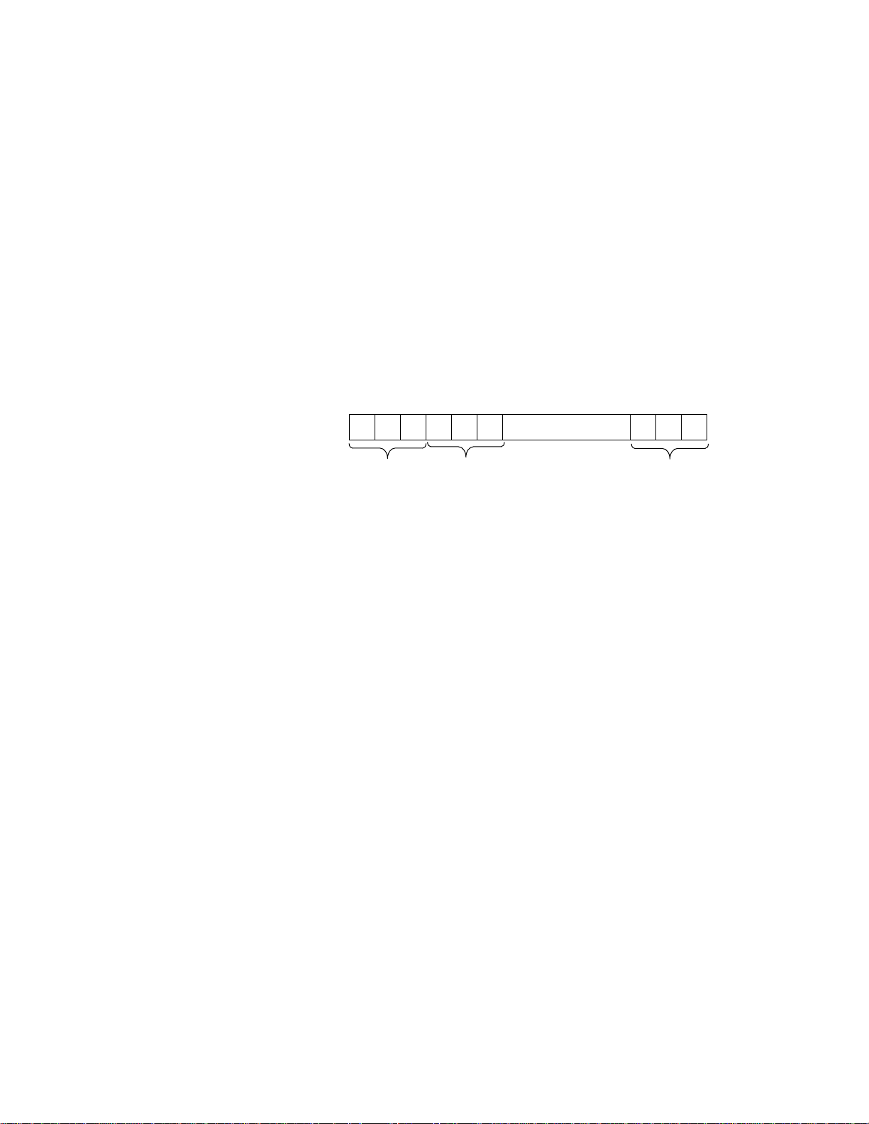
The printer.palette data set contains 48 elements; these elements define
the red, green, and blue color intensities of the 16 VIEWDAC screen
colors. Three elements are used to define each color; the first of the three
elements defines the red component, the second of the three elements
defines the green component, and the third of the three elements defines
the blue component. The first three elements of printer.palette define
VIEWDAC color #0 (black), the next three elements define VIEWDAC
color #1 (dark blue), and so on. Refer to Figure 2.
R G B R G B R G B
Element
. . . . . . . . . . . . . . . . .1 2 3 4 5 6 46 47 48
Color #0 Color #1 Color #15
Figure 2. Elements of the printer.palette Data Set
The value of each element ranges from 0 to 15, where 15 specifies the
highest intensity of the color and 0 specifies none of the color. For
example, the default values for VIEWDAC color #4 (dark red) are R=10,
G=0, and B=0; this specifies 10/15ths of the maximum red, no green, and
no blue. The default values for VIEWDAC color #15 (white) are R=15,
G=15, and B=15; this specifies the maximum red, the maximum green,
and the maximum blue.
To modify a color, perform the following steps:
1. Select Window\Data List... to display the Data Set Select dialog box.
2. Select printer.palette from the list of data sets, and then select the
View push button.
VIEWDAC displays the Data View dialog box showing the
printer.palette data set. Index refers to the element in the data set.
10 New Features
Page 22
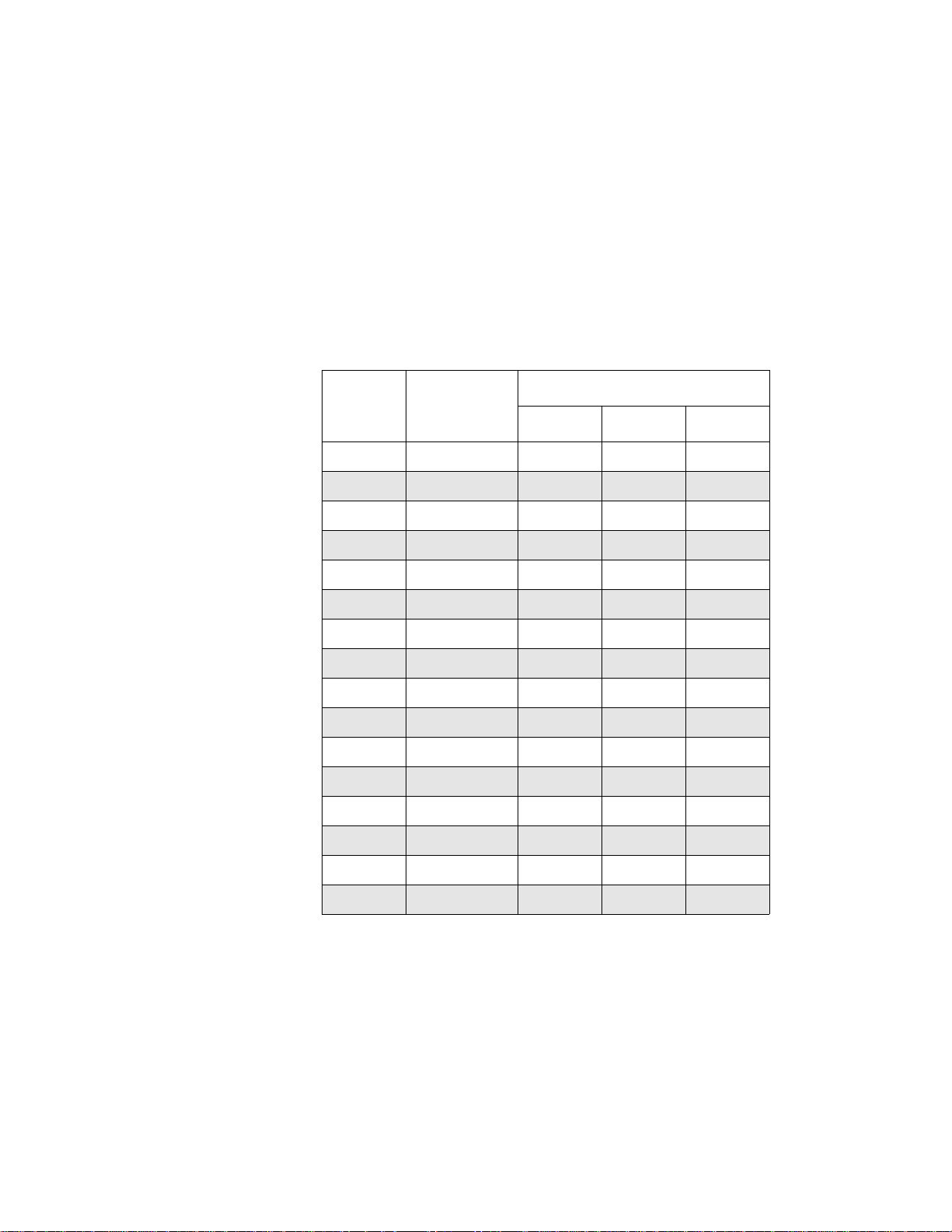
3. Determine which elements of the data set define the color you want to
modify. Refer to Table 1 for a list of VIEWDAC colors, the elements
that define the red, green, and blue components of the color, and the
default value of each element (in parentheses). The color names listed
refer to colors found on typical EGA and VGA systems.
Table 1. Elements of the printer.palette Data Set
Element
Color Name
0 Black 1 (0) 2 (0) 3 (0)
1 Dark blue 4 (0) 5 (0) 6 (10)
2 Dark green 7 (0) 8 (10) 9 (0)
3 Dark cyan 10 (0) 11 (10) 12 (10)
4 Dark red 13 (10) 14 (0) 15 (0)
5 Dark purple 16 (10) 17 (0) 18 (10)
6 Brown 19 (10) 20 (5) 21 (0)
7 Light gray 22 (10) 23 (10) 24 (10)
8 Dark gray 25 (5) 26 (5) 27 (5)
9 Light blue 28 (0) 29 (0) 30 (15)
10 Light green 31 (0) 32 (15) 33 (0)
11 Light cyan 34 (0) 35 (15) 36 (15)
12 Light red 37 (15) 38 (0) 39 (0)
13 Light purple 40 (15) 41 (0) 42 (15)
14 Yellow 43 (15) 44 (15) 45 (0)
Red Green Blue
15 White 46 (15) 47 (15) 48 (15)
11
Page 23

4. In the printer.palette data set, select a value you want to change,
enter the new value (between 0 and 15), and press [Tab].
For example, assume that you want to make color #1 (dark blue) a
little less blue. You can reduce the intensity of the blue component by
changing the value of element 6 from 10 to 5.
Note:
Make sure that you enter a value between 0 and 15. If you
enter any other value, the results will be unpredictable.
5. Continue until you have finished changing all the necessary values,
and then select the OK push button or press [Enter].
6. From the Data Set Select dialog box, select the OK push button or
press [Enter].
7. To save the new settings in your configuration file so that you do not
have to enter them every time you run VIEWDAC, select
System\Save Options.
Notes:
If you are using a printer that does not use RGB as the color
model, VIEWD A C automatically maps the RGB palette to the appropriate
color model for the printer you are using.
Any color mapping you specify in the Color Mapping table in the
Hardcopy Configuration dialog box is applied before the color palette in
the printer.palette data set is applied.
The effects of the changes you make to printer.palette vary depending on
such things as the way your printer uses colors, the color cartridge you are
using, the resolution of your printer, and the way your printer handles
dithering. You may have to try several different combinations of values in
printer.palette to find the best match to the color you want.
12 New Features
Page 24

13
Note:
Dithering is a technique used by most color printers to simulate
many more colors than they can actually print directly. For example,
assume that your color printer uses a cartridge that contains the three base
colors cyan, yellow, and magenta. To simulate additional colors, the
printer prints small dots of the base colors next to each other in a
particular pattern. When you look at the pattern, the dots merge together
and appear as a different color.
White on Black/Black on White
In VIEWDAC 2.2, if monochrome printing is selected (Mono radio
button in the Hardcopy Configuration dialog box), the White on
Black/Black on White radio buttons work exactly as they do in
VIEWDAC 2.1. Refer to the VIEWDAC Reference manual for more
information.
In VIEWDAC 2.2, if color printing is selected (Color radio button in the
Hardcopy Configuration dialog box), the quality of the printed image is
improved. The White on Black/Black on White radio buttons work as
follows:
White on Black - VIEWDAC 2.2 tries to simulate the screen image
●
colors as closely as possible. For example, if a graphics window on
the screen has a yellow sine wave on a blue background, the printed
image also has a yellow sine wave on a blue background; the colors
are not reversed as they are in VIEWDAC 2.1.
●
Black on White - The background color is always printed as white.
All non-background colors (except white) are printed as they appear
on the screen; anything that is white on the screen is printed in the
background color. For example, if a graphics window on the screen
has a yellow sine wave and a white cosine wave on a blue
background, the printed image has a yellow sine wave and a blue
cosine wave on a white background.
Page 25

Note:
determined by the setting of the Screen Background Back input box
in the System Configuration dialog box (displayed by selecting
System\Config... from the menu bar). Depending on the pen color and
pattern selected, the background color actually seen on the screen
may differ from the background color selected. For example, the
default screen background color is white (color 15); howev er , because
of the default pattern, the background appears as dark cyan (color 3).
Since the background color is white, printing the entire screen does
not reverse any colors.
Using Data Sets
When you save a sequence, information about any data sets used by the
sequence is saved with the sequence. (Only scalar data (not array data) is
saved with ASCII sequences; both scalar and array data are saved with
binary sequences.) Until you exit from VIEWDAC, the data sets are also
available in the system. When you reopen a saved sequence or open
another copy of a saved sequence, VIEWDAC encounters two data sets
with the same name.
When printing the entire screen, the background color is
In VIEWDAC 2.2, you can specify one of the following data set options
to determine what VIEWD A C should do when you open a sa ved sequence
and a data set with the same name is available in the system:
●
Allow you to decide on a case-by-case basis whether to reuse the data
set or create a new data set with a different name (rename the data
set).
●
Always rename the data set.
Reuse the data set in the system, if possible; if the data set cannot be
●
reused, rename the data set automatically.
●
Reuse the data set in the system, if possible; if the data set cannot be
reused, allow you to rename the data set manually.
14 New Features
Page 26

Reusing a data set is useful when you are developing a sequence and are
opening and closing the sequence often; in this case, you probably want
to use the same data set each time you edit the sequence. You may also
want to reuse a data set when you pass data between sequences, as when a
Call task starts a Block task in another sequence; refer to page 24 for
information about the Call task. Renaming a data set is useful if you want
to copy a sequence or if you want to load a sequence more than once with
a separate data set for each sequence.
Note:
specify a data set option for graphics windows and table editor windows.
For more detailed information about data set options, refer to page 18.
Types of Data Sets
VIEWDAC supports user-defined, autocreated, and system data sets.
These three different types of data sets are defined as follows:
●
User-defined data sets - You create user-defined data sets when you
select the New push button in the Data Set Select dialog box.
VIEWDAC considers two user-defined data sets with the same name,
size, and type as identical user-defined data sets; you can reuse
identical user-defined data sets. VIEWDAC considers two
user-defined data sets with the same name, but with different sizes
and/or types as different user-defined data sets; you cannot reuse
different user-defined data sets.
Note:
in the data set are the values that are currently in memory, not the
values saved with the sequence. Therefore, if you are reusing
identical user-defined data sets and your sequence requires
predictable initial values, it is recommended that your sequence
initialize the data set values.
You can specify a data set option for sequences only; you cannot
When you reuse an identical user-defined data set, the values
15
Page 27

Autocreated data sets - Some VIEWDAC tasks, such as the A to D
●
task, require a specific size and type of data. Whenever you add one
of these tasks to your VIEWDAC application, VIEWDAC
automatically creates an autocreated data set of the appropriate size
and type. You cannot reuse autocreated data sets.
●
System data sets - System data sets are the system variables, such as
counter and day.names , that are included in the VIEWD A C package.
You cannot rename system data sets.
Note:
When you start VIEWDAC, only system data sets are present.
Therefore, no data set name conflicts exist the first time you open a
sequence after starting VIEWDAC.
Specifying a Data Set Option
To specify which data set option you want to use, perform the following
steps:
1. Select System\Sequence Config... from the menu bar. The Sequence
Configuration dialog box contains the Data Set Name Conflict pop-up
menu, as shown in Figure 3.
16 New Features
Page 28

Pop-up
menu
17
Figure 3. Sequence Configuration Dialog Box
2. Select one of the following data set options from the Data Set Name
Conflict pop-up menu:
– Prompt
– Auto Rename
– Auto Reuse or Prompt
– Auto Reuse or Rename
These data set options are described in the following section.
3. To save the data set option in your configuration file so that you do
not have to select it every time you run VIEWDAC, select
System\Save Options.
Page 29

Data Set Options
Note:
System data sets are always reused, regardless of the data set
option you specify. Therefore, system data sets are not discussed in this
section.
The four data set options are described as follows:
●
Prompt - If you specify this option, each time you open a sequence
and VIEWDAC encounters a data set with the same name,
VIEWDAC displays the Data Set Name Conflict dialog box for each
existing data set. Figure 4 shows an example of the Data Set Name
Conflict dialog box.
Figure 4. Data Set Name Conflict Dialog Box
To reuse an identical user-defined data set, select the Reuse push
button; the name, type, and size of the data set are shown in the
Existing Data Set box. (The Reuse push button is grayed if the data
set name conflict exists between two autocreated or two different
user-defined data sets.)
18 New Features
Page 30

To create a new data set of the size and type shown in the New Data
Set box, select the Create push button after optionally specifying a
new name in the New name input box.
If you select the Create push button without entering a new name,
VIEWDAC uses the name shown in the New name input box; this is
the name of the existing data set appended by .x , where x is the next
available number that provides a unique name.
●
Auto Rename - If you specify this option, each time you open a
sequence and VIEWDAC encounters a data set with the same name,
VIEWDAC automatically creates a new data set of the same size and
type. VIEWDAC gives the new data set a unique name by appending
.x to the name of the existing data set, where x is the next available
number that provides a unique name.
Auto Rename is the default option. If you specify this option,
VIEWDAC 2.2 uses data sets in the same way that VIEWDAC 2.1
does.
● Auto Reuse or Prompt - If you specify this option, each time you
open a sequence and VIEWDAC encounters an identical user -defined
data set, VIEWDAC automatically reuses the data set in the system.
If VIEWD A C encounters an autocreated or different user -defined data
set with the same name, VIEWDAC displays the Data Set Name
Conflict dialog box with the Reuse push button grayed.
To create a new data set of the size and type shown in the New Data
Set box, select the Create push button after optionally specifying a
new name in the New name input box.
If you select the Create push button without entering a new name,
VIEWDAC uses the name shown in the New name input box; this is
the name of the existing data set appended by .x, where x is the next
available number that provides a unique name.
● Auto Reuse or Rename - If you specify this option, each time you
open a sequence and VIEWDAC encounters an identical user -defined
data set, VIEWDAC automatically reuses the data set in the system.
19
Page 31

If VIEWD A C encounters an autocreated or different user -defined data
set with the same name, VIEWDAC automatically creates a ne w data
set of the same size and type. VIEWDAC gives the new data set a
unique name by appending .x to the name of the existing data set,
where x is the next available number that provides a unique name.
Table 2 summarizes the actions VIEWDAC performs for each data set
option when encountering a data set with the same name.
Table 2. Action Performed when VIEWDAC
Encounters a Data Set with the Same Name
Type of Data Set Encountered
Identical
Data Set Option
Prompt Prompts to
Auto Rename Renames Reuses Renames Renames
Auto Reuse or Prompt Prompts to
Auto Reuse or Rename Renames Reuses Reuses Renames
Autocreated System
Reuses Prompts to
rename only
Reuses Reuses Prompts to
rename only
User-Defined
rename or reuse
Control Help Function
Each task in a sequence has a control list associated with it. To set up the
control list for each task, you place check marks in the appropriate control
cells of the Control dialog box. The check marks specify the following
control relationships:
● Which other tasks are started by the currently selected task
Different
User-Defined
Prompts to
rename only
rename only
● Which other tasks are stopped by the currently selected task
● Which other tasks start the currently selected task
● Which other tasks stop the currently selected task
20 New Features
Page 32

VIEWDAC 2.2 provides a Control Help box to facilitate the completion
of the Control dialog box. The Control Help box allows you to display an
English-like sentence, which you can use to either set up your control
relationships or describe a particular control relationship.
The Control Help functions are described in the following subsections.
Setting Up Control Relationships
To use the Control Help box to set up control relationships for a task,
perform the following steps:
1. Open the appropriate sequence, highlight the appropriate task, and
select the Control push button.
The Control dialog box contains the Control Help box at the bottom,
as shown in the example in Figure 5.
Currently selected task
Control cell
Control
relationship
sentence
Pop-up menu
Figure 5. Control Dialog Box
Input box
21
Page 33

Figure 5 shows the Control dialog box for a Push Button task called
Start Button, which is part of a sequence called TEST.SEQ. The task
whose control relationships you are setting up (Start Button) is
highlighted in the second line of the Control dialog box and is
displayed at the beginning of the control relationship sentence (the
first line in the Control Help box).
2. In the Control Help box, select the appropriate action from the pop-up
menu to the right of the task name. The available options are starts,
stops, is started by, and is stopped by.
In the example in Figure 5, the starts option was selected from the
pop-up menu.
3. Select the input box to the right of the pop-up menu and enter the
name of the task that completes the control relationship.
Note: You can also enter a task name by using Assistance, by using
the right mouse button to click on the appropriate task name in the
Task List at the top of the Control dialog box, or by using the arrow
keys to move the mouse pointer to the appropriate task name and then
pressing [Ctrl]+[spacebar].
In the example in Figure 5, Data Acquisition Loop w as entered in the
input box.
4. Read the control relationship sentence displayed across the first line
in the Control Help box. This sentence describes one of the possible
control relationships for your task. If the sentence describes one of
the control relationships you want, select the Set Control Relationship
push button. VIEWDAC automatically puts a check mark in the
appropriate control cell in the table at the top of the Control dialog
box.
22 New Features
Page 34

Notes: The Set Control Relationship push b utton is grayed if no task
name is entered in the input box.
If a control cell contains a check mark and the control relationship
sentence does not describe a desired control relationship, you can
select the Clear Control Relationship push button to remove the check
mark.
5. Repeat steps 2 through 4 for the other control relationships of your
task.
Note: By default, all tasks are initially active (the Initial State Active
toggle button at the bottom of the Control dialog box is enabled).
Therefore, by default, the Is Started By control cell for the sequence task
contains a check mark. In the example in Figure 5, by default, the Is
Started By control cell for TEST.SEQ contains a check mark. It is
recommended that you always verify the initial state of each task as you
set up your control relationships.
Describing Control Relationships
You can use the Control Help box to help you understand the meaning of
each control cell in the Control dialog box before you manually set up
your control relationships. You may also want to verify the meaning of a
particular check mark after you have set up your control relationships.
To display a sentence that describes what a check mark in a particular
control cell means, place the mouse pointer in the center of the control
cell and then either click the right mouse button or press
[Ctrl]+[spacebar]. The control relationship sentence (the first line of the
Control Help box) is updated with the appropriate action and task name.
If the control cell contains a check and the sentence does not describe a
desired control relationship, click on the left mouse button or select the
Clear Control Relationship push button to remove the check. If the
control cell does not contain a check and the sentence does describe a
desired control relationship, click on the left mouse button or select the
Set Control Relationship push button to add a check.
23
Page 35

For the example in Figure 5, the following control relationship sentences
are displayed when you place the mouse pointer in the control cells to the
left and right of the Data Acquisition Loop task and then either click the
right mouse button or press [Ctrl]+[spacebar]:
● Starts control cell - The sentence reads, "Start Button starts Data
Acquisition Loop." (Since you want the Start Button to start the Data
Acquisition Loop, there should be a check mark in the box.)
● Stops control cell - The sentence reads, "Start Button stops Data
Acquisition Loop." (Since you do not want the Start Button to stop
the Data Acquisition Loop, there should not be a check mark in the
box.)
● Is Started By control cell - The sentence reads, "Start Button is
started by Data Acquisition Loop." (Since you do not want the Data
Acquisition Loop to start the Start Button, there should not be a check
mark in the box.)
● Is Stopped By control cell - The sentence reads, "Start Button is
stopped by Data Acquisition Loop." (Since you do not want the Data
Acquisition Loop to stop the Start Button, there should not be a check
mark in the box.)
The Call Task
VIEWDAC 2.2 provides a new System task called the Call task. A Call
task is similar to a subroutine in programming and is useful when you
want to use the same set of tasks more than once in your VIEWDAC
application. Using Call tasks reduces the size of your VIEWDAC
application and allows you to load sequences faster.
The Call task starts a top-level Block task (which is in either the current
sequence or another sequence), waits for the Block task to complete, and
then runs its control list. A Call task does not pass any parameters to the
Block task it starts.
24 New Features
Page 36

Note: Y ou can specify only a top-le v el Block task. A top-level Block task
is a Block task that is not nested within another structured task. For
example, assume that your system contains the following Block tasks:
Block 1, Block 2 (which contains Block 3, Block 4, and Block 5), and
Block 6. A Call task can start Block 1, Block 2, or Block 6, but cannot
start Block 3, Block 4, or Block 5.
Differences Between Using a Call Task and a Control List
Any task can start another task or sequence through its control list. The
differences between using a control list and using a Call task are
described as follows:
● Control list - Through its control list, a task can start another
sequence or any top-level task within the current sequence. When a
task starts multiple tasks, all tasks run simultaneously. For example,
in Figure 6, Task B starts Block 2 through its control list. Assuming
that only Block 1 is initially active, Task A runs, then Task B runs.
When Task B completes, Task C and Task D begin to run
simultaneously.
Block 1
Task A
Task B
Task C
Figure 6. Using a Control List
Block 2
Task D
Task E
Task F
25
Page 37

When a task starts another task or sequence through its control list
and the task or sequence is already running, the task or sequence is
not started again.
Refer to the VIEWD A C Refer ence manual for more information about
setting task controls.
● Call task - A Call task can start only a top-level Block task. The Call
task waits for the Block task to start and complete before running its
control list. For example, in Figure 7, Call Task 1 starts Block 2.
Assuming that only Block 1 is initially active, the tasks run in the
following order: Task A, Task B, Task D, Task E, Task F, Task C.
Block 1
Task A
Task B
Call Task 1
Task C
Figure 7. Using a Call Task
Block 2
Task D
Task E
Task F
When a Call task attempts to start a top-level Block task and the
Block task is already running, the Call task continues to try to start
the Block task at regularly scheduled intervals. By default, the Call
task tries to start the Block task every 1 ms. You can change this
interval by using the set.call.repeat initialization file command in
your initialization file. For example, if you want the Call task to try to
start the Block task every 20 ms, include the line 20 set.call.repeat in
your initialization file. Refer to page 64 for more information about
26 New Features
Page 38

this initialization file command; refer to the VIEWDAC Reference
manual for more information about initialization files.
Finding Sequences Required by the Call Task
After you develop the sequence containing the Call tasks and the
sequences containing top-level Block tasks started by the Call tasks, you
start your sequence. When you start the sequence, VIEWDAC primes all
tasks, including the Call tasks. In priming the Call tasks, VIEWDAC first
searches for all sequences required by the Call tasks (those containing the
top-level Block tasks).
VIEWDAC uses the following method to search for a sequence when the
Call task is primed:
1. VIEWDAC searches memory for a sequence whose name and path
exactly matches the name and path you specified in the Call task.
2. VIEWDAC searches memory for any sequence with the name you
specified in the Call task (the path is ignored).
3. VIEWDAC searches on disk for a sequence whose name and path
exactly matches the name and path you specified in the Call task.
4. VIEWDAC searches on disk, in the directory from which the
sequence containing the Call task was loaded, for a sequence with the
name you specified in the Call task (the path is ignored).
Note: Because of the search method that VIEWDAC uses, it is
recommended that you do not have multiple sequences with the same
name.
When VIEWDAC finds a required sequence, it loads the sequence if it is
not already loaded, and starts the sequence if it is not already started.
Once the Call tasks are primed, they are started based on the control
relationships set up in the sequence.
27
Page 39

Notes: If a sequence required by a Call task is either closed or stopped
after the Call task is primed and before the Call task is started,
VIEWDAC returns an error when the Call task is started.
VIEWDAC also returns an error if a Block task started by a Call task
references (through control relationships) the Call task that started it; this
prevents your VIEWDAC application from getting into a deadlock
situation.
Adding a Call Task
Figure 8 shows the Call Task dialog box. A functional overview of the
Call task and a description of the items in the dialog box follow.
Figure 8. Call Task Dialog Box
Functional Overview
When Started: No special action.
Run Relative to Start: As soon as possible.
When Run: If the specified top-level Block task is not running, the Call
task starts the Block task; the Call task waits until the Block task
completes before running its control list. If the specified top-level Block
task is running, the Call task tries to start the Block task every 1 ms or at
28 New Features
Page 40

the interval specified in the initialization file. If the specified top-level
Block task is stopped by another task while running in response to a Call
task, the Call task runs its control list as if the Block task had completed
normally.
When Stopped: If the Call task is waiting for a top-level Block task to
complete, the Call task stops the specified Block task.
Name
Use the Name input box to change the Call task’s name. All Call tasks are
given the initial names Call 1, Call 2, and so on.
Sequence File
Use the Sequence File input box to enter the name of the sequence file
containing the Block task you want to start. The default sequence file is
the current sequence file, which is represented by an asterisk (*).
Notes: You can use Assistance to display a list of all currently loaded
sequences.
If the Block task you want to start is in the current sequence, it is
recommended that you use the asterisk, rather than the name of the
current sequence. This ensures that if you change the name of the
sequence, the Call task can still find it.
If the Block task you want to start is not in the current sequence, it is
recommended that you specify the complete path, if possible. If you
specify a file name only or an incorrect path for a file, VIEWDAC
provides as much of the complete path as it can. If VIEWDAC knows the
complete path (because the file has been saved to disk or because the file
was opened in the current VIEWDAC session), VIEWDAC fills in the
complete path or corrects the path appropriately. If you specify a file that
has not been saved to disk or a file that is not loaded in the system,
VIEWDA C accepts whate ver you specify, whether it is a complete path or
not. The file does not have to exist as yet.
29
Page 41

Block
Use the Block input box to enter the name of the Block task you want to
start. The Block input box is initially blank. You can enter any name you
want in the Block input box (the Block task does not have to exist as yet).
You can use Assistance to display a list of all currently loaded top-level
Block tasks in the specified sequence file.
Using Call Tasks with Library Sequences
A recommended way to use the Call task is to put your top-level Block
tasks in a library-type sequence and your Call tasks in an application
sequence, as follows:
1. Create the library sequence (for example, LIB.SEQ) for your
top-level Block tasks.
2. Save the sequence, specifying the complete path (for example,
C:\VIEWDAC\LIB.SEQ).
Note: Saving the sequence at this point ensures that when a Call task
starts one of the Block tasks in the sequence, the sequence name is
correct and the complete path is specified.
3. Include the top-level Block tasks in the library sequence, making sure
that the Block tasks are initially inactive.
Note: If the tasks are initially inactive, nothing unexpected happens
when the library-type sequence is started.
4. Create an application sequence (for example, APP.SEQ) for your Call
tasks and include the appropriate Call tasks in it. Refer to page 28 for
more information.
5. Edit the Block tasks in the library sequence, as necessary.
6. When you start the application sequence, VIEWD A C opens and starts
the library sequence automatically.
30 New Features
Page 42

Notes: If you want to pass data between the application sequence and the
library sequence, make sure that both sequences use the same data sets.
Refer to page 14 for more information on reusing the same data set.
Refer to the two example sequences, CALLEX1.SEQ and
CALLEX2.SEQ, and the descriptions of these sequences in the
DEMOS.DOC file for more information about using Call tasks in library
sequences and about sharing and passing data among data sets.
The Array Display Task
VIEWDAC 2.2 provides a new Panel task called the Array Display task.
The Array Display task displays the current values of a numeric or string
array data set. VIEWDAC places an array display in the front panel, as
shown in Figure 9.
Level indicator
Array display
Figure 9. Array Display in Front Panel
31
Page 43

Note: To display the current value of a scalar data set, use the Numeric
Display task, as you do in VIEWDAC 2.1. VIEWDAC places a numeric
display in the front panel. Refer to the VIEWDAC Reference manual for
more information.
An array display is different from a table window. An array display does
not contain a maximize, minimize, or close icon. In addition, since you
can display only one array at a time, the array display has only one data
column and no horizontal scroll bars. You can specify which element of
the array appears first in the array display. To display other elements of
the array, you can either click on the vertical scroll bar or use the
following keys:
● [Down arrow] - Moves down one line.
● [Up arrow] - Moves up one line.
● [Page Down] - Moves down the number of rows in the array display.
● [Page Up] - Moves up the number of rows in the array display.
● [Home] - Moves to the beginning of the array.
● [End] - Moves to the end of the array.
The array display in the front panel can contain level indicators that
change colors when the values of the data set go above or below one of
four threshold values. You modify the style aspects of the array display,
such as the level indicators and the threshold values, through the Array
Display Style dialog box; refer to page 34 for more information.
Adding an Array Display Task
Figure 10 shows the Array Display Task dialog box. A functional
overview of the Array Display task and a description of the items in the
dialog box follow.
32 New Features
Page 44

Figure 10. Array Display Task Dialog Box
Functional Overview
When Started: No special action.
Run Relative to Start: As soon as possible.
When Run: When an Array Display task is started, the displayed v alues in
the array display in the front panel are updated at the next available
foreground time.
The Array Display task evaluates the current values of the associated data
set and sets the indicator colors. It then converts the data set's values to
strings using the format strings supplied; these strings are displayed in the
array display in the front panel.
When Stopped: No special action.
Name
Use the Name input box to change the Array Display task's name. All
Array Display tasks are given the initial names Array Display 1, Array
Display 2, and so on.
Data
Type the name of an array data set in the Data input box to specify the
data set whose values are displayed in the array display in the front panel.
The default data set is the system data set cos.wave. You can use
Assistance to display a list of all appropriate array data sets.
33
Page 45

Panel
Select the Panel pop-up menu to list available front panels. The Array
Display task's array display resides in the currently selected front panel. If
the Array Display task is not currently assigned to a front panel, the P anel
pop-up menu displays Not Assigned.
Setting the Style of the Array Display
You can change the style of an array display in the front panel in one of
the following ways:
● By selecting the Style push button in the sequence window when an
Array Display task is highlighted.
● By double-clicking on an array display in a front panel when the
sequence is not running.
VIEWDAC displays the Array Display Style dialog box, as shown in
Figure 11. The Array Display Style dialog box contains a sample array
display . As you modify the style, the sample array display reflects the way
the array display will look and operate when the sequence is running.
34 New Features
Page 46

Sample array display
Figure 11. Array Display Style Dialog Box
Start Index
Use the Start Index input box to enter the element of the array that you
want to display first in the array display in the front panel. You can enter
either a constant value or the name of a data set. Y ou can use Assistance to
display a list of all appropriate data sets.
Note: As you scroll through the array display, VIEWDAC automatically
updates the constant value in the Start Index input box or the value of the
specified data set.
35
Page 47

Label
Use the Label input box to modify the heading of the data column in the
array display . If you enter text in the Label input box, VIEWDA C uses the
text for the data column heading. If you leave the Label input box blank,
VIEWDAC uses the name of the array data set as the data column
heading.
The maximum number of characters in a label is forty; the number of
characters displayed depends on the size of the array display and the size
and font chosen. If a label is too large, it is truncated.
By default, the Label input box is left blank.
Font
Use the Font pop-up menu to select the font style for the values in the
array display from a list of available fonts.
Size
Use the Size pop-up menu to select the font size for the values in the array
display from a list of available sizes. Not all fonts are available in all
sizes.
Value Active
If the Value Active toggle button is enabled, numbers appear in the array
display in the format specified by Value Format. If the Value Activ e toggle
button is disabled, no numbers appear in the array display.
If the Indicator Active toggle button is enabled, the colors and patterns of
the indicators in the array display change as the values of the data set
change. The Value Active toggle button is grayed if you are displaying a
string data set.
Value Format
Use the Value Format input box to enter the format of the numbers
displayed in the array display. You can use Assistance to display the
Number Format Select dialog box.
36 New Features
Page 48

The Value Format input box is grayed if you are displaying a string data
D
set.
Indicator Active
If the Indicator Active toggle button is enabled, VIEWDAC displays an
indicator color bead in each data row in the array display; the colors
change as the values cross one of the four threshold values. If the
Indicator Active toggle button is disabled, no color beads are displayed.
The threshold values, color, and pattern apply to all indicator color beads
in the array display. The Indicator Active toggle button is grayed if you
are displaying a string data set.
Indicator Value
Use the Indicator Value input boxes to specify the threshold values at
which the attributes of the color beads change. The attributes are
determined by the specified Indicator Color and Indicator Pattern.
You specify four threshold values to indicate five ranges. Assuming that
the four threshold values are A, B, C, and D (where ) and
≥≥≥
ABC
the data set value for a particular row is X, the five ranges at which the
color bead changes are as follows:
XA≥
AXB≥>
BXC≥>
CXD≥>
XD<
For example, assume that you use the default Indicator Values of 3, 1,
and
−3. If the data set value is greater than or equal to 3, the color bead is
−1,
displayed using the first Color and Pattern listed; if the data set value is
less than 3 and greater than or equal to 1, the color bead is displayed using
the second Color and Pattern listed; if the data set value is less than 1 and
greater than or equal to
Color and Pattern listed; if the data set value is less than
than or equal to
−3, the color bead is displayed using the fourth Color and
−1, the color bead is displayed using the third
−1 and greater
37
Page 49

Pattern listed; if the data set value is less than −3, the color bead is
displayed using the fifth Color and Pattern listed.
The Indicator Value input boxes are grayed if you are displaying a string
data set.
Indicator Color and Indicator Pattern
Use the Indicator Color and Indicator Pattern input boxes to enter the
numbers corresponding to the colors and patterns of the color beads
representing the current data ranges; samples of the current colors and
patterns are shown. Y ou can use Assistance to display all supported colors
and patterns.
The number of available colors is either two (for monochrome monitors)
or 16 (for color monitors); 32 different patterns are available. The
Indicator Color and Indicator Pattern input boxes are grayed if you are
displaying a string data set.
Pen Color
Use the Pen Color input box to enter the number corresponding to the pen
color of the array display label and displayed values; a sample of the
current pen color is shown. You can use Assistance to display all
supported pen colors.
The border around the array display is determined by the Border Color;
the horizontal and vertical lines in the array display are determined by the
Line Color.
Back Color
Use the Back Color input box to enter the number corresponding to the
background color of the array display; a sample of the current background
color is shown. You can use Assistance to display all supported
background colors.
Line Color
Use the Line Color input box to enter the number corresponding to the
color of the horizontal and vertical lines in the array display; a sample of
the current line color is shown. You can use Assistance to display all
supported line colors.
38 New Features
Page 50

Border Active
If the Border Active toggle button is enabled, a border is drawn around
the array display . If the Border Active toggle b utton is disabled, no border
is drawn around the array display.
Border Color
Use the Border Color input box to enter the number corresponding to the
color of the border around the array display; a sample of the current
border color is shown. You can use Assistance to display all supported
border colors.
Scroll Bar Active
If the Scroll Bar Active toggle button is enabled, a vertical scroll bar
appears in the array display in the front panel. If the Scroll Bar Active
toggle button is disabled, no scroll bars appear in the array display in the
front panel. The default state of the Scroll Bar Active toggle button is
enabled.
Row # Active
If the Row # Active toggle button is enabled, row numbers appear in the
array display in the front panel. If the Row # Active toggle button is
disabled, no row numbers appear in the array display in the front panel.
The default state of the Row # Active toggle button is enabled.
Col(umn) Heading Active
If the Col Heading Active toggle button is enabled, a heading appears
above the data column in the array display in the front panel; the actual
text in the column heading depends on whether you enter text in the Label
input box. If the Row # Active toggle button is enabled, the word "Row"
appears above the row numbers. If the Col Heading Active toggle button
is disabled, no column headings appear in the array display in the front
panel. The default state of the Col Heading Active toggle button is
enabled.
39
Page 51

40 New Features
Page 52

Software Enhancements
This section contains information about software enhancements that are
provided in VIEWDAC 2.2.
Window Support
VIEWDAC windows, such as sequence windows, table editor windows,
and front panels, contain window items. The number of window items in
a particular window depends on the type of window; typically each
window contains three to nine window items. In VIEWDAC 2.2, up to
5,120 window items can be open simultaneously, allowing approximately
700 windows. In addition, VIEWDAC 2.2 does not limit the number of
scroll bars that can be open simultaneously; VIEWDAC allocates scroll
bars as they are needed.
Note: In VIEWDAC 2.1, only 255 window items can be open
simultaneously. The number of scroll bars that can be open
simultaneously is also limited.
Scrolling
In VIEWDAC 2.2, scrolling through items in a window or dialog box
using a single click of the mouse button is more consistent. Each time you
single-click on an up or down scroll arrow, the window or dialog box
moves up or down one line. Each time you single-click on the scroll bar
above or below the scroll box (for vertical scroll bars) or to the left or
right of the scroll box (for horizontal scroll bars), the window or dialog
box moves up, down, left, or right one screen.
41
Page 53

Note: In VIEWDAC 2.1, a single click of the mouse button, particularly
on faster computers, may move the windo w or dialog box several lines or
several screens.
Removing Data Sets
VIEWDAC 2.2 provides a new push button, labeled Remove All, in the
Data Set Select dialog box. You can select the Remove All push button to
delete data sets as follows:
● If you accessed the Data Set Select dialog box by selecting
Window\Data List... from the menu bar, VIEWDAC deletes all
user-defined data sets from the system, even if they are currently in
use.
Depending on the location of the user-defined data set, the data set is
either removed, replaced with a constant value, or replaced with the
null.scalar or unnamed.array data set.
Note: You cannot access a data set replaced with null.scalar or
unnamed.array; these names are used for internal purposes only.
● If you accessed the Data Set Select dialog box through Assistance,
VIEWDAC deletes all unused, user-defined data sets from the
currently displayed Data Set Select dialog box. Data sets that are
currently in use are not deleted; data sets that are not displayed in the
Data Set Select dialog box are not deleted.
When you select the Remove All push button, VIEWDAC displays a
warning box with an Abort and a Continue push button. Select the Abort
push button to cancel the operation. Select the Continue push button to
remove the appropriate data sets.
42 Software Enhancements
Page 54

Notes: The Remove All push button does not delete autocreated and
system data sets.
Unless the Data Set Select dialog box contains at least one data set that
can be removed, the Remove All push button is grayed.
Manipulating Tasks
In VIEWDAC 2.2, when you paste or duplicate a task, the name of the
pasted or duplicated task is the same as the name of the task that you
originally cut or copied. This is useful when you are copying multiple
tasks. You can keep better track of the copied tasks because the names are
meaningful to you. In addition, fewer changes are required when you edit
the names of the copied tasks.
Note: In VIEWDA C 2.1, when you paste or duplicate a task, the name of
the pasted or duplicated task is the VIEWDAC default task name with a
numeric suffix that gives it a unique name.
For example, a sequence called TEST.SEQ contains a Loop task called
Data Acquisition Loop, which contains an A to D task called Measure
Temperature of Boiler Room; the automatically created Begin task is
named Data Acquisition Loop Begin and the automatically created End
task is named Data Acquisition Loop End. Table 3 shows the difference
between the ways these tasks are pasted or duplicated in VIEWDAC 2.2
and VIEWDA C 2.1.
43
Page 55

Table 3. Names of Pasted and Duplicated Tasks
Task Name VIEWDAC 2.2 VIEWDAC 2.1
Data Acquisition Loop Data Acquisition Loop Loop 2
Data Acquisition Loop Begin Data Acquisition Loop Begin Loop 2 Begin
Measure T emperature of
Boiler Room
Data Acquisition Loop End Data Acquisition Loop End Loop 2 End
Note: If using the VIEWDAC default task names (as in VIEWDAC 2.1)
is more suitable to your needs, you can specify this naming scheme by
including the default.tasknames.on.edit initialization file command in
your initialization file. To return to the VIEWDAC 2.2 naming scheme
(the name of the pasted or duplicated task is the same as the name of the
task that you originally cut or copied), you can either include the
user.tasknames.on.edit initialization file command in your initialization
file or remove the default.tasknames.on.edit initialization file command
from your initialization file. Refer to page 64 for more information about
these initialization file commands; refer to the VIEWDAC Reference
manual for more information about initialization files.
Modal Front Panels
Measure T emperature of
Boiler Room A to D 2
If you are creating a VIEWDAC application that uses modal front panels,
you must use a Hide/Show task to hide the modal front panel. However,
sometimes, in the process of developing and debugging your application,
you may find yourself in a modal front panel with no way to hide the front
panel. In VIEWDAC 2.2, you can use the [F10] key to recover without
restarting the computer. When you press [F10], VIEWDAC sounds a bell,
hides the modal front panel, and stops the associated sequence.
44 Software Enhancements
Page 56

Note: In VIEWDAC 2.1, if you do not provide a way to hide a modal
front panel, you must restart your computer to continue. If you have not
saved your sequence, you will lose any work you have already completed.
Snap-to-Grid Option
VIEWDA C 2.2 pro vides a snap-to-grid option, which allo ws you to mov e
or size a front panel object, such as a numeric display or a push button, to
a particular line on an invisible grid. Enabling the snap-to-grid option is
useful when you want to align objects in the front panel or ensure that
objects are the same size. Disabling the snap-to-grid option is useful
when you want to move objects freely to any location in the front panel or
size objects freely to any size.
When you start VIEWDAC, the snap-to-grid option is disabled. You can
enable the snap-to-grid option in one of the following ways:
● Select Panel\Snap To Grid - A check mark indicates that the
snap-to-grid option is enabled. Any front panel object that you move
or size snaps to the invisible grid automatically. Select Panel\Snap To
Grid again to disable the snap-to-grid option.
Note: The Snap To Grid option is grayed if a sequence is running.
If you use this method to enable or disable the snap-to-grid option
and then select System\Save Options, the snap-to-grid setting is sav ed
in your configuration file so that you do not have to set it every time
you run VIEWDAC. The snap-to-grid setting applies to all front
panels in all sequences.
● Press [Ctrl] and hold it down while moving or sizing an object -
The particular front panel object that you are moving or sizing snaps
to the invisible grid.
45
Page 57

With the snap-to-grid option enabled, use the mouse to move or size a
front panel object. As you move or size the object, the object snaps to the
nearest line on the invisible grid. The distance between each grid line is
equal to the size of one character (8 pixels by 8 pixels).
Note: String input boxes and numeric input boxes always snap to the
invisible grid, whether the snap-to-grid option is enabled or disabled.
PCX Files
The following subsections describe changes to the type and number of
PCX files that are supported in VIEWDAC 2.2.
Types of PCX Files Supported
In VIEWDAC 2.2, you can import a wider variety of PCX graphics files
than you can in VIEWDAC 2.1. In addition, VIEWDAC 2.2 reproduces
colors in PCX files more accurately than VIEWDAC 2.1 does. PCX files
are bitmap files that you can use as a background for a front panel or a
graphics window. You can create a PCX file in Windows
in one of several DOS-based and Windows-based graphics packages.
Paintbrush or
The following versions of Paintbrush-compatible PCX files are
supported:
● All Version 2.0 and 3.0 files.
● Version 5.0 16-color, 256-color, and 24-bit color files.
Number of PCX Files Supported
In VIEWDAC 2.2, you can maintain a larger number of PCX files. The
PCX files are created when you press either [Ctrl]+[F4] (to print the
active window or open dialog box to a PCX file) or [Ctrl]+[F3] (to print
the entire screen to a PCX file).
46 Software Enhancements
Page 58

VIEWDAC gives each of the first 100 PCX files the name
SCREENxx.PCX, where xx is a number from 0 to 99. For PCX files
numbered higher than 99, VIEWD A C uses as man y digits to the left of the
period (.) as are required. For example, the 203rd PCX file is named
SCREE203.PCX.
Note: In VIEWDAC 2.1, you can print a maximum of 100 windows
and/or screens to PCX files (SCREEN0.PCX through SCREEN99.PCX).
Strip Chart Task
In VIEWDAC 2.2, an Enable Strip Chart Clear toggle button has been
added to the Strip Chart Style dialog box, as shown in Figure 12.
Toggle button
Figure 12. Strip Chart Style Dialog Box
47
Page 59

D to A Task
The Enable Strip Chart Clear toggle button determines whether the
display is cleared when the Strip Chart task is restarted; the Strip Chart
task is considered restarted the first time it is started after it has been
stopped. If the Enable Strip Chart Clear toggle button is enabled, each
time the Strip Chart task is restarted, VIEWDAC clears the display before
continuing to display data. If the Enable Strip Chart Clear toggle button is
disabled and the Strip Chart task is restarted, VIEWDAC does not clear
the previous data on the screen and continues displaying data.
Note: VIEWDAC 2.1 operates as if the Enable Strip Chart Clear toggle
button were disabled. When the Strip Chart task is restarted, VIEWDAC
does not clear the previous data on the screen,
Some external DAS drivers provide information about the analog output
range supported by the associated DAS de vice. If the external DAS driver
you are using provides this information, VIEWDAC 2.2 uses the
information to check the analog output values you specify in a D to A
task. You specify the analog output values in the data sets specified in the
Data Name input boxes in the D/A Task dialog box. If any of the values
are higher than the highest value supported by the DAS device,
VIEWDAC causes the DAS device to output the highest value supported;
if any of the values are lo wer than the lowest value supported by the DAS
device, VIEWDAC causes the DAS device to output the lowest value
supported. For example, if your DAS device supports an analog output
range of ±5 V and you specify an output value of +8.75 V, VIEWDAC
causes the DAS device to output +5 V; if you specify an output value of
−8.75 V, VIEWDAC causes the DAS device to output −5 V.
Note: VIEWDAC 2.1 does not check the analog output value; the DAS
device attempts to output whatever value you specify. For example, if
your DAS device supports an analog output range of ±5 V and you
specify an output value of +8.75 V, the DAS device attempts to output
+8.75 V; if you specify an output value of
attempts to output −8.75 V.
48 Software Enhancements
−8.75 V, the DAS device
Page 60

Event Counting Task
In VIEWD AC 2.2, when you stop an Event Counting task, the count stops
and the updated count value is written to the specified data set. The value
read from the data set after you stop the Event Counting task is the
updated count value.
Note: In VIEWDAC 2.1, when you stop an Event Counting task, the
count stops but the final count value is not written to the specified data set.
49
Page 61

50 Software Enhancements
Page 62

This section contains information that was either missing from or
incorrect in the VIEWDAC Reference manual.
Entering Numbers
Numbers in VIEWDAC can be represented in either decimal, binary,
octal, or hexadecimal format (base of 10, 2, 8, or 16, respectively). For
numbers that are output by VIEWDAC, such as numbers that are
displayed by a Numeric Display task, you use the Number Format Select
dialog box to specify the base, as well as other aspects of the number
format. Refer to the VIEWDAC Reference manual for more information.
For numbers that you enter in VIEWDAC, such as the numbers you enter
in an input box created by a Numeric Input task, you can specify the base
only. You cannot control other aspects of the number format, such as
leading zeros and place-holding characters.
Errata
You specify the base by appending a suffix to the number. Table 4 lists the
bases supported, the suffix used for each, and an example of what to enter
to represent the decimal value of 10.
Table 4. Number Bases
Base Suffix Example
10 (decimal) None 10
2 (binary) %b or %B 1010%b
8 (octal) %o or %O 12%o
16 (hexadecimal) %h or %H A%h
51
Page 63

By default, whenever you enter a number, VIEWDAC assumes a base of
10 (decimal format).
When entering numbers in VIEWDAC, you can use scientific notation to
enter numeric values that require more places than VIEWDAC provides.
For example, to specify the number 1,000,000, you can enter 1E6; to
specify the number 0.0000967, you can enter 9.67E-5.
String Data Sets
On page 1-19 of the VIEWDAC Reference manual, under String, note that
you can save a numerical expression (function) as a string data set so that
you do not have to enter the expression more than once. This is useful
where functions are used, as in Curve Fitting and Expressions. When you
press [F2] from a function input box, the Data Set Select dialog box lists
available strings that you can use as functions.
Array Space
On page 1-62 of the VIEWDAC Reference manual, under Array Space in
the Memory Status dialog box, note that the default initial array space is
64K bytes, not 128K bytes. In addition, the default amount of space
allocated when the array space requests more memory is 64K bytes, not
128K bytes.
Color Mapping
On page 1-91 of the VIEWDAC Reference manual, under Color Mapping
in the Hardcopy Configuration dialog box, note that a plotter hardcopy
device always places a border around the plotter output. You cannot
control the border color through VIEWD A C; it is al ways the color of your
plotter’s pen 1. The Color Mapping table is used for non-border colors
only.
52 Errata
Page 64

For example, assume that you want the border of the plotter output to be
dark green, and you want everything that is either dark green or light
green on the screen to also be dark green in the plotter output. First, make
sure that your plotter’s pen 1 is dark green. Then, map both dark green
(color 2) and light green (color 10) to pen 1 in the Hardcopy
Configuration dialog box (Color 2 = Mapped Color (pen) 1 and
Color 10 = Mapped Color (pen) 1).
The border color of plotter output used to send encapsulated PostScript
(EPS) is always black. To modify the border color, you can send the EPS
output to an EPS file and then modify the file. (Note that the border, if
requested, is printed at the end of each plot.)
Saving Binary Sequences
On page 2-16 of the VIEWDAC Reference manual, under Sequence
Window, note that since data is saved with binary sequences, you should
make sure that you have sufficient disk space before saving sequences as
binary files.
Using PCX Files in Front Panels
On page 2-34 of the VIEWDAC Reference manual, under Background
Color in the Front Panel dialog box, note that all front panels contain a
border whose color is the same as the front panel’s background color. If
you use a PCX file as a background for a front panel, the border remains
displayed. If the color of the front panel’s border does not match the color
of the PCX file, you can change the border color to match the
predominant color of the PCX file by performing the following steps:
1. Select Panel\Style from the menu bar to display the Front Panel
dialog box.
2. Enter the appropriate color code in the Background Color input box.
53
Page 65

Hide/Show Task
On page 4-59 of the VIEWD A C Refer ence manual, note that you can use a
Hide/Show task in conjunction with a Time Trigger task to create a front
panel that disappears after a specified period of time. To create a front
panel that disappears after 30 seconds, perform the following steps:
1. Designate a front panel as modal.
2. Add two Hide/Show tasks: one that displays the modal front panel
and one that hides the modal front panel.
3. Add a Time Trigger task with a delay time of 30 seconds (Data is set
to 30,000 ms).
4. From the Hide/Show task that displays the front panel, start the Time
Trigger task.
5. From the Time Trigger task, start the Hide/Show task that hides the
front panel.
Absolute Time T rigger T ask
On page 5-16 of the VIEWDAC Reference manual, under Date/T ime, note
that a value of 659.5 corresponds to October 21, 1981, not
September 21, 1981.
54 Errata
Page 66

Threshold Task
On pages 5-24 and 5-25 of the VIEWDAC Reference manual, under
Operation, the descriptions of the four operations are incorrect. The
correct descriptions are as follows:
X < A then X > A (rising edge)
Result is 1 if at first X is less than A and then X becomes greater than A;
otherwise, result is 0. This operation can occur for data sets that have a
positive slope (increasing in value).
X > A then X < A (falling edge)
Result is 1 if at first X is greater than A and then X becomes less than A;
otherwise, result is 0. This operation can occur for data sets that have a
negative slope (decreasing in value).
X < B then X > A (rising edge)
Result is 1 if at first X is less than B and then X becomes greater than A;
otherwise, result is 0. This operation can occur for data sets that have a
positive slope (increasing in value).
Note: To ensure that Result becomes 1 only on a rising edge, make sure
that A is greater than B.
X > A then X < B (falling edge)
Result is 1 if at first X is greater than A and then X becomes less than B;
otherwise, result is 0. This operation can occur for data sets that have a
negative slope (decreasing in value).
Note: To ensure that Result becomes 1 only on a falling edge, make sure
that A is greater than B.
55
Page 67

Calc Tasks
On page 6-1 of the VIEWDAC Reference manual, note that for Calc tasks
that require a Result data set, such as the Numeric Operation task and the
Statistic Operation task, you must be aware of the numeric type and size
of Result. The calculation operation is performed internally to full
precision and size. However, since the numeric type and size of Result is
fixed, the internal results may be altered when they are placed in Result.
Numeric Operation Task
On page 6-23 of the VIEWDAC Reference manual, under the Round(X)
Operation, note that negative real numbers are rounded to the next lowest
integer. For example, given X =
Note: In the function ROUND(A), which is used for Analysis
expressions, negative real numbers are rounded to the next highest
integer. For example, in the expression Y = ROUND(−1.5), Y = −1.0.
−1.5, Round(X) = −2.0.
Array Operation Task
On page 6-26 of the VIEWD AC Refer ence manual, under Operations, note
that the operations Ramp(X) and Fill(X,A,B) create scaled arrays of a
specified size and then fit these arrays into the Result array. To create
scaled arrays that are the exact size of the Result array, make sure that X
is less than or equal to zero. For the Expression task and the
Analysis\Expression\Evaluate Expression menu option, X must be greater
than zero.
56 Errata
Page 68

String Operation Task
On page 6-48 of the VIEWDAC Reference manual, note that you can use
the String Operation task to concatenate strings to create automatically
incremented file names. For example, assume that you are acquiring 25
sets of data and you want each set of data written to a unique file; you
want the files to be named scan0.dat to scan24.dat. You can set up a
Loop task as follows:
Loop task: Set Start to 0, Stop to 25, and Incr(ement) to 1.
A to D task: Set up your analog input operation as appropriate.
String Operation task: String1=Number>String(counter,scan#0.dat)
where counter is the Current loop index (specify counter in the
Current input box of the Loop task) and scan#0.dat is the format
string.
VIEWDA C Write task: Specify String1 as the file name; add all the
data sets from the A to D task that you want to include in your files.
Data I/O Tasks
On page 7-1 of the VIEWDAC Reference manual, note that you can use
Data I/O tasks to write data to and read data from VIEWDAC arrays,
computer I/O ports, and computer memory (RAM), as well as data files
on disk. For example, the Array Write task writes data to a VIEWDAC
array, the Array Read task reads data from a VIEWDAC array, the
Poke/Peek task reads data from or writes data to computer memory, and
the Port I/O task reads data from or writes data to a computer I/O port.
Another Data I/O task, the DOS task, performs file I/O operations, such
as delete and copy, on a specified file.
In addition, note that the speed at which Data I/O file tasks run is reduced
significantly when the DOS environment variable VERIFY is set to ON.
(Data I/O file tasks include all Data I/O tasks except the DOS task, the
Poke/Peek task, and the Port I/O task.) You can improve Data I/O file task
performance by setting VERIFY to OFF. However, keep in mind that
setting VERIFY to OFF disables all checking of data written to the disk.
57
Page 69

DAS Tasks
A to D Task
On page 8-4 of the VIEWD AC Reference manual, under About Data Sets,
note that you may find it useful to move data acquired using a D AS task to
another data set and then use the new data set whenever you need the
acquired data. For example, assume that you performed an A to D task
and stored the acquired data in the autocreated data set A_to_D_1.0. You
can use a Numeric Operation task to move the data; use the operation
R:=X, where X = A_to_D_1.0 and Result = the new data set. If you ever
change the DAS task (for example, change the channel or type of task),
just change the X data set in the Numeric Operation task; all other tasks
using the new data set (Result) will still be valid.
Note: All references to the autocreated data set are lost when you move
the data to a new data set.
On page 8-10 of the VIEWDAC Reference manual, under Scan Rate, note
that the scan rate you specify is the rate (in Hertz) at which all channels in
a scan are sampled; it is also the rate at which any one particular channel
in a scan is sampled (also called the sample rate). The time between each
conversion of the entire scan (in seconds) is the inverse of the scan rate
(1 / Scan Rate).
For example, if your scan consists of four channels (0, 1, 2, and 3) and
you specify a scan rate of 1000 (1 kHz), channel 0 is sampled at a scan
rate of 1 kHz, channel 1 is sampled at a scan rate of 1 kHz, and so on. The
time required to sample the entire scan is 1 ms. Refer to Figure 13.
58 Errata
Page 70

0 1 2 3 0 1 2 3
0.001 s (1 ms) = scan rate of 1 kHz
Figure 13. Scan Rate
The time between each conversion within a scan is determined by the
following equation:
In the example in Figure 13, the time between a conversion on channel 0
and a conversion on channel 1 is 250
to a rate of 4 kHz. This is not the scan rate you specify in the A/D Task
dialog box.
Thermocouple Task
On page 8-27 of the VIEWDAC Reference manual, under Sample Rate,
note that the sample rate you specify is the rate (in Hertz) at which all the
channels in the scan are sampled (also called the scan rate). The time
required to sample the entire scan (in seconds) is the inverse of the sample
rate (1 / Sample Rate).
For example, if your scan consists of three channels (0, 1, and 2) and you
specify a sample rate of 200 (200 Hz), the time required to sample the
entire scan is 5 ms. Refer to Figure 14.
-------------------------------------------------------------Scan Rate # of channels×
1
µs (1 / (1,000 x 4)). This translates
59
Page 71

0
0.005 s (5 ms) = sample rate of 200 Hz
1 2
Figure 14. Sample Rate
The time required to sample each channel within a scan is determined by
the following equation:
In the example in Figure 14, the time between the sampling of channel 0
and the sampling of channel 1 is 1.66 ms (1 / (200 x 3)). This translates to
a rate of 600 Hz. This is not the sample rate you specify in the
Thermocouple Task dialog box.
Counter/Timer Tasks
On page 8-47 of the VIEWDAC Reference manual, under About
Counter/Timer Support, note that the way a particular counter/timer task
works depends on the DAS device you are using. For example, the Event
Counting task counts either high pulses or low pulses, depending on the
DAS device. Refer to your external DAS driver documentation for more
information.
-------------------------------------------------------------------Sample Rate # of channels×
1
60 Errata
Page 72

Pulse Output Task
On page 8-53 of the VIEWDAC Reference manual, under Pulse Width,
note that the pulse width you specify is always the total pulse period (the
active pulse width plus the inacti ve pulse width or the time from when the
pulse goes active until the pulse goes active again). The active state of a
pulse (high or low) is hardware-dependent. For example, if a particular
DAS device produces pulses that are active-high, the pulse period is the
time from when the pulse goes high until the pulse goes high again.
In continuous pulse mode, the duty cycle determines the percent of the
total pulse period that the pulse is active. For e xample, if a particular D AS
device produces pulses that are active-high and you specify a duty cycle
of 20%, the pulse is high for 20% of the pulse period and low for 80% of
the pulse period. If you specify a pulse width of 10 ms in the Pulse Output
Task dialog box, the pulse is high for 2 ms and low for 8 ms, as shown in
Figure 15.
Pulse Width = 10 ms
2 ms
8 ms Duty Cycle = 20%
Figure 15. Continuous Pulse Mode
The duty cycle also affects the width of the pulse in one-shot pulse mode.
If you use the default duty cycle of 50% in one-shot pulse mode, the
output pulse is half as long as the pulse width specified. For example, if
you specify a pulse width of 10 ms using the default duty cycle of 50%
for a DAS device that produces active-high pulses, the device produces a
one-shot output pulse of 5 ms, as shown in Figure 16.
61
Page 73

Graphics
Pulse Width = 10 ms
Duty Cycle = 50%
5 ms
Figure 16. One-Shot Pulse Mode
For one-shot pulse mode, to ensure that the pulse width you specify is the
actual length of the output pulse, make sure that you set the duty cycle to
100%.
On page 11-3 of the VIEWDAC Reference manual, under Selecting
Plotted Data Sets, note that if you are plotting large data sets or many data
sets in a graphics window, using the legend to select a data set is faster
than clicking directly on the plotted data set.
Table Editor
On page 13-3 of the VIEWDAC Reference manual, note that you can
quickly inspect data sets in a table editor window during sequence
execution. First, display the data sets in the table editor window; then, use
a Macro task to redraw the table editor window.
62 Errata
Page 74

Using an X Data Set in Analysis Operations
On page 14-3, of the VIEWDAC Reference manual, under VIEWDAC’s
Assumptions about Data, note that differentiation and integration
operations may return unexpected results if you do not use an X array.
The definition of the derivative for differentiation and integration
operations is . If you do not associate an X array with the
data, the differentiation routine assumes that the dx value is 1. Since this
is usually not the correct value, the results may be incorrect.
For example, when differentiated without an X array, sin.wave gives a
cosine wave with an amplitude of 0.01744, rather than an amplitude of 1
as might be expected. To ensure that your results come out as expected,
create a ramp from 0 to 2
dy() dx()÷
π for the X array and plot X versus Y.
Rounding Numbers in Analysis Operations
On page 14-46 of the VIEWDAC Reference manual, under the function
ROUND, note that both positi ve and negati ve real numbers are rounded to
the next highest integer. For example, in the expression
Y = ROUND(1.5), Y = 2; in the expression Y = ROUND(
−1.5), Y = −1.0.
Note: In the Round(X) operation of the Numeric Operation task, positi ve
real numbers are rounded to the next highest integer; negative real
numbers are rounded to the next lowest integer. For example, given
X = 1.5, Round(X) = 2; given X = −1.5, Round(X) = −2.0.
63
Page 75

Macros
On page 15-2 of the VIEWDA C Refer ence manual, in step 3 of recording a
macro, note that before you press [Alt]+[M] or click on the End Macro
message, you must wait until all the keystrokes you are recording have
been executed, not just until all the keys have been pressed. If you press
[Alt]+[M] or click on the End Macro message before all the keystrokes
have been executed, some of the keystrokes may be lost.
New Initialization File Commands
On page A-5 of the VIEWDAC Reference manual, under VIEWDAC.INI
Initialization File, note that VIEWDAC 2.2 provides five new
initialization (INI) file commands. These commands are described in
Table 5.
Refer to the VIEWDAC Reference manual for more information about
initialization files and initialization commands.
64 Errata
Page 76

Table 5. New Initialization File Commands
Function Command Description
Sequence default.tasknames.on.edit Uses the following naming convention for pasted or
duplicated tasks: the name of the pasted or
duplicated task is the VIEWDAC default task name
with a numeric suffix that gives it a unique name.
For example, if you include the line
default.tasknames.on.edit in your INI file and you
copy a Meter task called Temperature of Boiler
Room, the pasted task is called Meter x, where x is
the next number that gives the task a unique name.
user.tasknames.on.edit Uses the following naming conv ention for pasted or
duplicated tasks: the name of the pasted or
duplicated task is the same as the name of the
copied or cut task.
For example, if you include the line
user.tasknames.on.edit in your INI file and you
copy a Meter task called Temperature of Boiler
Room, the pasted task is also called Temperature of
Boiler Room.
n set.call.repeat Sets the time interval at which a Call task continues
to try to start an already active Block task to n
milliseconds. The default repeat interval is 1 ms.
For example, if you include the line
5000 set.call.repeat in your INI file, the Call task
tries to start the Block task every 5 s.
System disable.uart.fifos Disables the FIFOs on any 16550 UART RS-232
chips in your computer. This ensures that your serial
mouse and your RS-232 ports work properly.
n%h m%h set.nmi.mask Disables parity error checking, where n and m
represent mask values for your particular computer.
For example, the line 0C0%h 0C%h set.nmi.mask
should work for most computers; the line
FF%h 0%h set.nmi.mask is required for Zenith
machines.
65
Page 77

Initialization File Command Example
On page A-12 of the VIEWDAC Reference manual, note that the
command on the last line of the second example should have a period (.)
between text and edit. The correct command line is as follows:
file.open.text.edit c:\data\expt1.dat
Using Pre-emption
On page B-1 of the VIEWDAC Reference manual, note that memory for
data sets is allocated from different sources, depending on whether
pre-emption is enabled or disabled. Therefore, memory allocated when
pre-emption is enabled is not available when pre-emption is disabled and
memory allocated when pre-emption is disabled is not available when
pre-emption is enabled. If you intend to enable and disable pre-emption
frequently, make sure that you have sufficient memory or make sure that
you run VIEWDAC in virtual memory mode.
Interpreting Numeric Literals
On page D-4 of the VIEWDAC Reference manual, under External
Language Interface, note that numeric literals in expressions are
interpreted as either DP.REALs or DP .INTEGERs, depending on the way
you enter the number. If you enter the number with a period (.), the
number is interpreted as a DP.REAL; if you enter the number without a
period, the number is interpreted as a DP.INTEGER. For example, the
number 1.0 is interpreted as a DP.REAL; the number 1 is interpreted as a
DP.INTEGER.
66 Errata
Page 78

Watcom C Compiler
On page D-7 of the VIEWDAC Reference manual, under External
Language Interface, note that you can use VIEWDAC with Watcom C 9.0
only. The current version, Watcom C 9.5, is not supported; previous
versions, such as Watcom C 8.5, are also not supported.
Task Scheduling
On page E-4 of the VIEWDAC Reference manual, note that some of the
information on where Data I/O tasks are performed is incorrect. The
correct information is shown in Table 6.
67
Page 79

Table 6. Where Data I/O Tasks are Performed
Task Location
DOS Foreground
DOS (copy only) Multiple Slices
Array Write Background
Array Read Background
ASCII Write Split & Buffered
ASCII Read Foreground
Binary Write Split & Buffered
Binary Read Foreground
VIEWDAC Write Split & Buffered
VIEWDAC Read Foreground
ASYST Write Split & Buffered
ASYST Read Foreground
ASYSTANT Write Split & Buffered
1
1
1
1
1
ASYSTANT Read Foreground
Port I/O Background
Poke/Peek Background
Note
1
Buffered only if all involved data sets are
scalars.
68 Errata
Page 80

binary sequences
Index
A
Abort push button
Absolute Time Trigger task
Active toggle button
adding a Call task
adding an Array Display task
aligning objects
allocating memory
analog output values
analysis operations
array display
34
style
Array Display Style dialog box
Array Display task
adding
functional overview
Array Display Task dialog box
Array Operation task
Array Read task
array space
Array Write task
ASCII sequences, converting to binary
A to D task
autocreated data sets
Auto Rename data set option
Auto Reuse or Prompt data set option
Auto Reuse or Rename data set option
32
52
sequences
B
Back Color input box
background color of screen
base of numbers
58
32
45
57
51
57
42
28
66
5
63
31
23
48
56
16
38
,
36
33
54
,
14
37
32
19
,
34
32
39
19
19
compatibility issues
converting to ASCII sequences
saving
Black on White radio button
Block input box
Block task, top-level
Border Active toggle button
border color for plotter output
Border Color input box
53
30
4
4
13
25
39
52
39
C
Calc tasks
Call task
Call Task dialog box
CFG file: see configuration file
changing a color
checking analog output values
Clear Control Relationship push button
clearing a strip chart display
Col Heading Active toggle button
Color input box
color mapping
color printing
Color radio button
colors, VIEWDAC
commands
compatibility with VIEWDAC 2.1
configuration file
Continue push button
continuous pulse mode
56
24
26
,
adding
functional overview
28
28
28
10
,
38
39
,
12
52
9
13
,
13
11
,
64
66
default.tasknames.on.edit
26
65
9
65
,
65
44
12
17
,
,
,
3
disable.uart.fifos
set.call.repeat
set.nmi.mask
user.tasknames.on.edit
compatibility issues
42
61
47
45
48
44
,
65
39
,
65
3
23
X-1
Page 81

control cells
Control dialog box
Control Help function
control list
control relationships
describing
setting up
converting a VIEWDAC 2.1 ASCII sequence
25
24
23
21
20
,
20
21
5
converting a VIEWDAC 2.1 binary sequence
4
counter/timer tasks
Create push button
creating incremented file names
creating new data sets: see renaming data sets
creating scaled arrays
60
19
57
56
D
DAS tasks 58
Data input box 33
Data I/O tasks 57
Data Set Name Conflict dialog box 18
Data Set Name Conflict pop-up menu 16
data set options 18
Auto Rename 19
Auto Reuse or Prompt 19
Auto Reuse or Rename 19
Prompt 18
specifying 16
data sets 14
autocreated 16
different user-defined 15
identical user-defined 15
removing 42
string 52
system 16
types 15
user-defined 15
Data Set Select dialog box 42
default.tasknames.on.edit initialization file
command
deleting data sets 42
describing control relationships 23
dialog boxes
Array Display Style
Array Display Task 32
Call Task 28
Control 20, 21
Data Set Select 42
Data Set Name Conflict 18
Hardcopy Configuration 7, 9, 12, 13
Sequence Configuration 16
Strip Chart Style 47
differentiation operations 63
different user-defined data sets 15
disable.uart.fifos initialization file command
44, 65
34
65
dithering 13
DOS task 57
D to A task 48
duplicating tasks 43
duty cycle 61
E
Enable Strip Chart Clear toggle button 47
entering numbers 51
Event Counting task 49
X-2 Index
Page 82

F
file I/O operations 57
finding sequences 27
Font pop-up menu 36
Format input box 36
format of numbers 51
front panels, modal 44
functional overview
Array Display task
Call task 28
33
G
graphics 62
graphics files: see PCX files
grid, aligning objects to
45
input boxes
Back Color
Block 30
Border Color 39
Data 33
Indicator Color 38
Indicator Pattern 38
Indicator Value 37
Label 36
Line Color 38
Name 29, 33
Pen Color 38
Sequence File 29
Start Index 35
Value Format 36
integration operations 63
38
L
H
Hardcopy Configuration dialog box 7, 9, 12,
13
Hide/Show task 54
hiding a front panel 44, 54
high resolution 9
I
identical user-defined data sets 15
incrementing file names 57
Indicator Active toggle button 37
Indicator Color input boxes 38
Indicator Pattern input boxes 38
Indicator Value input boxes 37
indicators 32
INI file commands: see commands
initialization file commands: see commands
Initial State Active toggle button
23
Label input box 36
level indicators: see indicators
library sequences
Line Color input box 38
local printer connection 8
Location radio buttons 7
low resolution 9
30
X-3
Page 83

M
macros 64
compatibility issues 5
manipulating tasks 43
mapping colors 12, 52
medium resolution 9
memory allocation 66
modal front panels 44
modifying a color 10
monochrome printing 13
Mono radio button 13
moving data 58
N
Name input box 29, 33
names of tasks 43
network printer connection 8
number bases 51
numeric literals 66
Numeric Operation task 56
O
one-shot pulse mode 61
open scroll bars 41
open window items 41
plotting graphics 62
Poke/Peek task 57
pop-up menus
Data Set Name Conflict
Font 36
Panel 34
Size 36
Port I/O task 57
pre-emption 66
priming tasks 27
printer.palette data set 9
printers
connection to your computer
resolution 9
supported 7
printing
color
9, 13
monochrome 13
Prompt data set option 18
Pulse Output task 61
pulse period: see pulse width
pulse width
push buttons
Abort
Clear Control Relationship 23
Continue 42
Create 19
Remove All 42
Reuse 18
Set Control Relationship 22
61
42
16
7
P
R
Panel pop-up menu 34
Panel tasks
Array Display task
pasting tasks 43
Pattern input boxes 38
PCX files 46, 53
Pen Color input box 38
X-4 Index
31
radio buttons
Black on White
Color 13
Location 7
Mono 13
Resolution 9
White on Black 13
13
Page 84

ranges of data 37
Remove All push button 42
removing data sets 42
renaming data sets 15
resolution of printed image 9
Resolution radio buttons 9
Reuse push button 18
reusing data sets 15
rounding numbers 56, 63
Row # Active toggle button 39
S
sample rate
A to D task
Thermocouple task 59
saving binary sequences 53
scaled arrays 56
scaling images 9
scan rate
A to D task
Thermocouple task 59
scheduling tasks 67
scientific notation 52
screen background color 14
Scroll Bar Active toggle button 39
scroll bars 41
scrolling 41
searching for sequences 27
Sequence Configuration dialog box 16
Sequence File input box 29
sequences
finding
library-type 30
set.call.repeat initialization file command 26,
65
Set Control Relationship push button 22
set.nmi.mask initialization file command 65
setting up control relationships 21
Size pop-up menu 36
58
58
27
snap-to-grid option 45
Start Index input box 35
stopping an Event Counting task 49
string data sets 52
String Operation task 57
Strip Chart Style dialog box 47
Strip Chart task 47
style of the array display 34
system data sets 16
System tasks
Call task
24
T
table editor window 62
task names 43
task scheduling 67
tasks, manipulating 43
Thermocouple task 59
threshold indicators: see indicators
Threshold task
threshold values 37
toggle buttons
Border Active
Col Heading Active 39
Enable Strip Chart Clear 47
Indicator Active 37
Initial State Active 23
Row # Active 39
Scroll Bar Active 39
Value Active 36
top-level Block task 25
55
39
U
upgrading from VIEWDAC 2.1 3
user.tasknames.on.edit initialization file
command
user-defined data sets 15
44, 65
X-5
Page 85

V
Value Active toggle button 36
Value Format input box 36
Value input boxes 37
VERIFY environment variable 57
VIEWDAC colors 11
W
Watcom C compiler 67
White on Black radio button 13
window items 41
X-6 Index
 Loading...