

Page 1

PDMA-16 Parallel Digital Interface Board
User Guide
A GREATER MEASURE OF CONFIDENCE
Page 2

WARRANTY
Hardware
Keithley Instruments, Inc. warrants that, for a period of one (1) year from the date of shipment (3 years for Models 2000, 2001, 2002, 2010 and 2700), the
Keithley Hardware product will be free from defects in materials or workmanship. This warranty will be honored provided the defect has not been caused
by use of the Keithley Hardware not in accordance with the instructions for the product. This warranty shall be null and void upon: (1) any modification of
Keithley Hardware that is made by other than Keithley and not approved in writing by Keithley or (2) operation of the Keithley Hardware outside of the
environmental specifications therefore.
Upon receiving notification of a defect in the Keithley Hardware during the warranty period, Keithley will, at its option, either repair or replace such Keithley Hardware. During the first ninety days of the warranty period, Keithley will, at its option, supply the necessary on site labor to return the product to the condition prior to
the notification of a defect. Failure to notify Keithley of a defect during the warranty shall relieve Keithley of its obligations and liabilities under this warranty.
Other Hardware
The portion of the product that is not manufactured by Keithley (Other Hardware) shall not be covered by this warranty, and Keithley shall have no duty of
obligation to enforce any manufacturers' warranties on behalf of the customer. On those other manufacturers’ products that Keithley purchases for resale,
Keithley shall have no duty of obligation to enforce any manufacturers’ warranties on behalf of the customer.
Software
Keithley warrants that for a period of one (1) year from date of shipment, the Keithley produced portion of the software or firmware (Keithley Software) will
conform in all material respects with the published specifications provided such Keithley Software is used on the product for which it is intended and otherwise in accordance with the instructions therefore. Keithley does not warrant that operation of the Keithley Software will be uninterrupted or error-free and/
or that the Keithley Software will be adequate for the customer's intended application and/or use. This warranty shall be null and void upon any modification
of the Keithley Software that is made by other than Keithley and not approved in writing by Keithley.
If Keithley receives notification of a Keithley Software nonconformity that is covered by this warranty during the warranty period, Keithley will review the
conditions described in such notice. Such notice must state the published specification(s) to which the Keithley Software fails to conform and the manner
in which the Keithley Software fails to conform to such published specification(s) with sufficient specificity to permit Keithley to correct such nonconformity. If Keithley determines that the Keithley Software does not conform with the published specifications, Keithley will, at its option, provide either the
programming services necessary to correct such nonconformity or develop a program change to bypass such nonconformity in the Keithley Software.
Failure to notify Keithley of a nonconformity during the warranty shall relieve Keithley of its obligations and liabilities under this warranty.
Other Software
OEM software that is not produced by Keithley (Other Software) shall not be covered by this warranty, and Keithley shall have no duty or obligation to
enforce any OEM's warranties on behalf of the customer.
Other Items
Keithley warrants the following items for 90 days from the date of shipment: probes, cables, rechargeable batteries, diskettes, and documentation.
Items not Covered under Warranty
This warranty does not apply to fuses, non-rechargeable batteries, damage from battery leakage, or problems arising from normal wear or failure to follow
instructions.
Limitation of Warranty
This warranty does not apply to defects resulting from product modification made by Purchaser without Keithley's express written consent, or by misuse
of any product or part.
Disclaimer of Warranties
EXCEPT FOR THE EXPRESS WARRANTIES ABOVE KEITHLEY DISCLAIMS ALL OTHER WARRANTIES, EXPRESS OR IMPLIED, INCLUDING WITHOUT LIMITATION, ALL IMPLIED WARRANTIES OF MERCHANTABILITY AND FITNESS FOR A PARTICULAR PURPOSE. KEITHLEY DISCLAIMS ALL WARRANTIES WITH RESPECT TO THE OTHER HARDWARE AND OTHER SOFTWARE.
Limitation of Liability
KEITHLEY INSTRUMENTS SHALL IN NO EVENT, REGARDLESS OF CAUSE, ASSUME RESPONSIBILITY FOR OR BE LIABLE FOR: (1)
ECONOMICAL, INCIDENTAL, CONSEQUENTIAL, INDIRECT, SPECIAL, PUNITIVE OR EXEMPLARY DAMAGES, WHETHER CLAIMED
UNDER CONTRACT, TORT OR ANY OTHER LEGAL THEORY, (2) LOSS OF OR DAMAGE TO THE CUSTOMER'S DATA OR PROGRAMMING, OR (3) PENALTIES OR PENALTY CLAUSES OF ANY DESCRIPTION OR INDEMNIFICATION OF THE CUSTOMER OR OTHERS FOR
COSTS, DAMAGES, OR EXPENSES RELATED TO THE GOODS OR SERVICES PROVIDED UNDER THIS WARRANTY.
Keithley Instruments, Inc. 28775 Aurora Road • Cleveland, Ohio 44139 • 440-248-0400 • Fax: 440-248-6168
1-888-KEITHLEY (534-8453) • www.keithley.com
Sales Offices:BELGIUM: Bergensesteenweg 709 • B-1600 Sint-Pieters-Leeuw • 02-363 00 40 • Fax: 02/363 00 64
CHINA: Yuan Chen Xin Building, Room 705 • 12 Yumin Road, Dewai, Madian • Beijing 100029 • 8610-6202-2886 • Fax: 8610-6202-2892
FINLAND: Tietäjäntie 2 • 02130 Espoo • Phone: 09-54 75 08 10 • Fax: 09-25 10 51 00
FRANCE: 3, allée des Garays • 91127 Palaiseau Cédex • 01-64 53 20 20 • Fax: 01-60 11 77 26
GERMANY: Landsberger Strasse 65 • 82110 Germering • 089/84 93 07-40 • Fax: 089/84 93 07-34
GREAT BRITAIN: Unit 2 Commerce Park, Brunel Road • Theale • Berkshire RG7 4AB • 0118 929 7500 • Fax: 0118 929 7519
INDIA: Flat 2B, Willocrissa • 14, Rest House Crescent • Bangalore 560 001 • 91-80-509-1320/21 • Fax: 91-80-509-1322
ITALY: Viale San Gimignano, 38 • 20146 Milano • 02-48 39 16 01 • Fax: 02-48 30 22 74
JAPAN: New Pier Takeshiba North Tower 13F • 11-1, Kaigan 1-chome • Minato-ku, Tokyo 105-0022 • 81-3-5733-7555 • Fax: 81-3-5733-7556
KOREA: 2FL., URI Building • 2-14 Yangjae-Dong • Seocho-Gu, Seoul 137-888 • 82-2-574-7778 • Fax: 82-2-574-7838
NETHERLANDS: Postbus 559 • 4200 AN Gorinchem • 0183-635333 • Fax: 0183-630821
SWEDEN: c/o Regus Business Centre • Frosundaviks Allé 15, 4tr • 169 70 Solna • 08-509 04 679 • Fax: 08-655 26 10
SWITZERLAND: Kriesbachstrasse 4 • 8600 Dübendorf • 01-821 94 44 • Fax: 01-820 30 81
TAIWAN: 1FL., 85 Po Ai Street • Hsinchu, Taiwan, R.O.C. • 886-3-572-9077• Fax: 886-3-572-9031
4/02
Page 3
PDMA-I
6
Parallel Digital Interface Board
User Guide
Keithley Instruments, Inc.
Aurora Road, Cleveland,
28775
Technical
Monday ~ Friday
Support:
Fax:
http://www.keithle yxom
1-888-KEITHLEY
8:OO
a.m.
(440)
248-6168
to
OH
5:OO
44139
p.m.
(EST)
Q
1986
Keithley
All
Cleveland,
Second
[hruiiient
righls
Ohio,
Prinling,
Number:
Instruments,
reservad.
U
S.A.
Jdnuilry
1992
24885
Inc.
Rev.
B
Page 4
BasicLM
IBM"
is
PC,
XT,
is a trademark
of
Dartmouth College.
a registered trademark
AT,
PS/2,
and Micro Channel Architecture@
of
International Business Machines Corporation
arc tradcrnarks
of
Intcrnational Busincss Machincs Corporation.
Microsofta
Turbo
Tnirxnialion
is a registered trademark
C"
IS
a
registered trademark
1-ui-nished
hy
Keithley
assumes no responsihility for
that
partics
may result from
Keithley Instruments.
Keithley Instruments assumes no responsibility for damages consequent to
the use
of
this product. This product is not designed with components of
reliability suitable for use in life support
the
its
use
usc.
ol'
Microsol'L Corporation.
ot
Borland International
Inslrumenls
of
such information nor for any infringements
No
liccnsc
is believed
is
granted
to
be accurale
by
implication or otherwise under any patcnt rights
WARNING
or
critical applications.
and
reliahle. However, Keilhley
of
patents or other rights of third
a
level
Instrurnenls
of
of
Page 5

Safety Precautions
The following safety precautions should be observed before using
this product and any associated instrumentation. Although some instruments and accessories would normally be used with non-hazardous voltages, there are situations where hazardous conditions
may be present.
This product is intended for use by qualified personnel who recognize shock hazards and are familiar with the safety precautions required to avoid possible injury. Read and follow all installation,
operation, and maintenance information carefully before using the
product. Refer to the manual for complete product specifications.
If the product is used in a manner not specified, the protection provided by the product may be impaired.
The types of product users are:
Responsible body is the individual or group responsible for the use
and maintenance of equipment, for ensuring that the equipment is
operated within its specifications and operating limits, and for ensuring that operators are adequately trained.
Operators use the product for its intended function. They must be
trained in electrical safety procedures and proper use of the instrument. They must be protected from electric shock and contact with
hazardous live circuits.
Maintenance personnel perform routine procedures on the product
to keep it operating properly, for example, setting the line voltage
or replacing consumable materials. Maintenance procedures are described in the manual. The procedures explicitly state if the operator
may perform them. Otherwise, they should be performed only by
service personnel.
Service personnel are trained to work on live circuits, and perform
safe installations and repairs of products. Only properly trained service personnel may perform installation and service procedures.
Keithley products are designed for use with electrical signals that
are rated Installation Category I and Installation Category II, as described in the International Electrotechnical Commission (IEC)
Standard IEC 60664. Most measurement, control, and data I/O signals are Installation Category I and must not be directly connected
to mains voltage or to voltage sources with high transient over-voltages. Installation Category II connections require protection for
high transient over-voltages often associated with local AC mains
connections. Assume all measurement, control, and data I/O connections are for connection to Category I sources unless otherwise
marked or described in the Manual.
Exercise extreme caution when a shock hazard is present. Lethal
voltage may be present on cable connector jacks or test fixtures. The
American National Standards Institute (ANSI) states that a shock
hazard exists when voltage levels greater than 30V RMS, 42.4V
peak, or 60VDC are present. A good safety practice is to expect
that hazardous voltage is present in any unknown circuit before
measuring.
Operators of this product must be protected from electric shock at
all times. The responsible body must ensure that operators are prevented access and/or insulated from every connection point. In
some cases, connections must be exposed to potential human contact. Product operators in these circumstances must be trained to
protect themselves from the risk of electric shock. If the circuit is
capable of operating at or above 1000 volts, no conductive part of
the circuit may be exposed.
Do not connect switching cards directly to unlimited power circuits.
They are intended to be used with impedance limited sources.
NEVER connect switching cards directly to AC mains. When connecting sources to switching cards, install protective devices to limit fault current and voltage to the card.
Before operating an instrument, make sure the line cord is connected to a properly grounded power receptacle. Inspect the connecting
cables, test leads, and jumpers for possible wear, cracks, or breaks
before each use.
When installing equipment where access to the main power cord is
restricted, such as rack mounting, a separate main input power disconnect device must be provided, in close proximity to the equipment and within easy reach of the operator.
For maximum safety, do not touch the product, test cables, or any
other instruments while power is applied to the circuit under test.
ALWAYS remove power from the entire test system and discharge
any capacitors before: connecting or disconnecting cables or jumpers, installing or removing switching cards, or making internal
changes, such as installing or removing jumpers.
Do not touch any object that could provide a current path to the common side of the circuit under test or power line (earth) ground. Always
make measurements with dry hands while standing on a dry, insulated
surface capable of withstanding the voltage being measured.
The instrument and accessories must be used in accordance with its
specifications and operating instructions or the safety of the equipment may be impaired.
Do not exceed the maximum signal levels of the instruments and accessories, as defined in the specifications and operating information, and as shown on the instrument or test fixture panels, or
switching card.
When fuses are used in a product, replace with same type and rating
for continued protection against fire hazard.
Chassis connections must only be used as shield connections for
measuring circuits, NOT as safety earth ground connections.
If you are using a test fixture, keep the lid closed while power is applied to the device under test. Safe operation requires the use of a
lid interlock.
5/02
Page 6

If or is present, connect it to safety earth ground using the
wire recommended in the user documentation.
!
The symbol on an instrument indicates that the user should refer to the operating instructions located in the manual.
The symbol on an instrument shows that it can source or measure 1000 volts or more, including the combined effect of normal
and common mode voltages. Use standard safety precautions to
avoid personal contact with these voltages.
The WARNING heading in a manual explains dangers that might
result in personal injury or death. Always read the associated information very carefully before performing the indicated procedure.
The CAUTION heading in a manual explains hazards that could
damage the instrument. Such damage may invalidate the warranty.
Instrumentation and accessories shall not be connected to humans.
Before performing any maintenance, disconnect the line cord and
all test cables.
To maintain protection from electric shock and fire, replacement
components in mains circuits, including the power transformer, test
leads, and input jacks, must be purchased from Keithley Instruments. Standard fuses, with applicable national safety approvals,
may be used if the rating and type are the same. Other components
that are not safety related may be purchased from other suppliers as
long as they are equivalent to the original component. (Note that selected parts should be purchased only through Keithley Instruments
to maintain accuracy and functionality of the product.) If you are
unsure about the applicability of a replacement component, call a
Keithley Instruments office for information.
To clean an instrument, use a damp cloth or mild, water based
cleaner. Clean the exterior of the instrument only. Do not apply
cleaner directly to the instrument or allow liquids to enter or spill
on the instrument. Products that consist of a circuit board with no
case or chassis (e.g., data acquisition board for installation into a
computer) should never require cleaning if handled according to instructions. If the board becomes contaminated and operation is affected, the board should be returned to the factory for proper
cleaning/servicing.
Page 7
~
....
CHAPTER
1
:
INTRODUCTION
Contents
1.1 General Description
1.2 Applications
1.3 Features
1.4 Accessories
CHAPTER
CHAPTER
2:
INSTALLATtON
2.1 Unpacking
2.2 Backing
2.3 Base Address Switch
2.4 Other Settings
2.5
2.6 3oard Installation
3.1
3.2 Ports A
3.3
3.4 Interrupt Control Register
3.5
I/O
Connector
3:
REGISTER STRUCTURES
I/O
Map
DMA Control Register
8254 Timer
.......................................
.........................................
.......................................
&
Inspecting
Up
Distribution Software
.........................................
&
B
.......................................
.......................................
...................................
................................
...........................
..................................
......................................
.....................................
....................................
.................................
................................
1.1
1.1
1.1
1.2
2.1
2.1
2.2
2.3
-2-4
2.5
3.1
3.1
3.2
3.3
3.3
CHAPTER
CHAPTER
4:
PROGRAMMING
4.1 The PDMA-16 Call Modes
4.2 Programming In BASlCA
Loading The Machine Language CALL Routine PDMAl6.BIN
Format
Execution Times
4.3 Programming In QuickBASIC
Loading The Program
Declaring The Driver
Format
Making Executable Programs
5:
THE
MODE
5.1
5.2
5.3
5.4
5.5
5.6
5.7
5.8
5.9
5.10
5.11
Overview
MODE
MODE 1
MODE 2: Return Status
MODE
MODE 4: Digital Output
MODE
MODE
MODE
MODE
MODE 9: Allocate Memory For DMA
0:
:
3:
5:
6:
7:
8:
FOR
Of
The CALL Statement
Of
The Call Statement
CALLS
........................................
Initialize The PDMA-16 Driver & Check Hardware
Set
Up
&
Set Timer Rate
Digital Input
Auxiliary Output
Setup & Interrupt Enable
Disable Interrupt
THE CALL
MODES
IN BASICA & QUICKBASIC
...............................
................................
..........
..........................
.
Compiled BASIC
........................
.............................
................................
...............................
...........................
...........................
............
Perform DMA Transfer
......................
................................
...............................
................................
.................................
...............................
.........................
..............................
........................
4.1
4.1
4.1
4.3
4.4
4.4
4.4
-4-5
4.5
4.7
5.1
5-1
5.2
5.5
5.6
5-7
5-8
5-9
5-10
5-12
5-13
-v-
Page 8
Con
tents
5.12 MODE
5.13
5.14
CHAPTER
6.1 The
6.2
CHAPTER
7.1 Typical Handshake Connection
7.2
7.3 High Speed
7.4
CHAPTER
8.1 Senrice & Repair.
8.2
MODE 11
MODE
6:
PROGRAMMABLE INTERVAL
Reading & Loading
7:
APPLICATIONS
Waveform Generation
Combined
8:
MAINTENANCE & REPAIR
Performing Your Own Repairs
10:
Deallocate Memory Segment
:
Move Data From Source
12:
Disable DMA
8254
Programmable Interval
The
AID
Conversion
A/D
8t
D/A Conversion Using Directional Controls
...................................
.....................
To
Destination.
..............................
TIMER
Timer
Counters.
............................
With
a D/A Converter.
.............................
............................
.......................
..........................
....................
...............
............
5-14
5-14
5-15
6-1
6-3
7-1
7-2
7-3
7-4
8-1
8-1
APPENDICES
A
Appendix
Appendix
Appendix C Understanding DMA
Appendix D Modes
Appendix
Appendix F PDMA-16 PCF
Specifications
B
Summary
9
E
Storage
Of
Error Codes
i3
10:
AllocatelDeallocate
of
Integer Variables
DMA
...
Buffers
-
vi-
Page 9
CHAPTER
1
.I
GENERAL
The
PDMA-15
plugs directly into an expansion slot
AT&T
rear mounting plate.
63300.
1
DESCRIPTION
high-speed, labit, paralleldigital interface card
All
digital
1/0
feeds
of
the IBM
through
PC/XT/AT
a 37-pin,
D-type,
INTRODUCTION
with
DMA (Direct Memory Access)
and compatible machines, including the
male connector
that
projects through the
Compared with standard digital
with its internal
than can be achieved with programmed
around
rate of the computer's main processor and the clock supplied
transfer rates of 200,000 bytes/sec or 120,000 words/sec are possible on
4.77h4Hz
time.
constantly output
1.2
Typical applications for the
1.
2.
3.
4.
5.
5-IOKHz).
It
is
APPLICATIONS
Interface
Arbitrary waveform generation with an external D/A converter.
High-speed
High-speed digital stimulus
Fast block transfer of data between computers.
clock.
possible
for
DMA
and interrupt-control hardware is capable
Actual DMA data transfer rates are computer dependent, influenced by the clock
Note
that the
to
transfer any number
or
input to a bIock
high-speed digital peripherals.
A/D
conversion with an external
1/0
boards
DMA
controller may address only one page (64Kbytes)
of
PDMA-16
for
testing
(such
as the Keithley MetraByte PIO-121, the PDMA-16
1/0
transfers
of
bytes
memory using the
are as follows:
and
through
up
A/D
control.
the
to
to
this
limit as a singleshot operation,
DMA
converter.
of
much higher data transfer
main
processor (at best limited
the
8237
DMA controller. Continuous
a
standard
IBM
of
Controller's Auto-initialize Mode.
rates
PC
with
memory at a
or
to
to
6.
Interrupt or DMA driven background data transfers.
7.
High sink current
8.
Data line monitoring.
9.
Transient generation and monitoring.
1.3
FEATURES
The PDMA-16 includes the following features:
1.
Two
8-bit
1/0
The ports are addressable as normal 1/0 locations using programed transfer
instructions), or by using the
at
high
speed
lTL
digital
ports,A
to/from the ports from/to memory. DMA transfers maybe bytes (&bit) through
and
1/0
B.
Each port is settable as an input
Pc's
internal 8237
(24mA sink current).
DMA
or
output under software control.
controller. Data may
(IN
and
OUT
be
directly transferred
1/0
1-1
Page 10
PDMA-16
USER GUIDE
the A Port
DIRECTION outputs provide information on the current direction of the
interface to devices capable
AUXl
utilized in general control
use as a regular
2.
A
DMA transfer may
The internal timer consists
counter.
choice of external signal
the
XFER
transfer to/from memory is acknowledged
the high state. The operating DMA level is selectable as either Level
The user
commencing transfers.
3.
An
interrupt channel
Level
pin, a periodic interrupt
from the
only,
or
words
-
AUX3
(2-7)
are
available from the DMA and Interrupt Control Registers and can
port
for
be
This
provides a
REQUEST input, the
is
required
and
8237
to
is
choose
DMA controller.
(16
bit) using both the A and B Ports. The A DIRECTION and
of
bidirectional data transfer.
and
handshake functions. In
programmed
initiated by
of
a
loMHz
clock
rate ranging from
or
internal clock
XFER
initialize the
also provided. Software control allows
between a positive-
from
the
I/O.
an
external signal
crystal oscillator divided through two
2.5MHz
is
via
software
ACKNOWLEDGE
by
the
XFER
8237
DMA
controller
or
negative-edge external interrupt on the
PDMA-16's
internal timer,
In
Byte
(XFER
to
control.
output goes low. Completion
ACKNOWLEDGE
on
addition,
DMA transfers, the
REQUEST)
0.0023Hz
the
PC
you
or
a terminal interrupt generated
B
ports
to
simplify
three
auxiliary outputs,
be
further
B
Port
is
or
by
the internal timer.
sections
(about 8 pulses/hr), The
On
receipt
1
system board before
to select the active Intempt
of
a positive edge on
output returning to
or
3
under software control.
of an
of
INTERRUPT
free
8254
the
for
1.4
ACCESSORIES
A
set
of
software drivers for interpreted Microsoft BASIC, compiled BASIC,
Assembly Language are included in the Distribution Software. Because
applications, interrupt service routines, etc. the drivers perform basic
functions such as setting up the
the
for
user-developed drivers. Some simple
driver (PDMA.ASM) is supplied and can serve as a starting point for more application-specific,
DMA
Controller and internal Timer. Fully commented source code
BASIC
test and example programs are also included.
...
and
QuickBASIC, and
of
variety of possible
commom-to-all-application
1-2
Page 11
CHAPTER
This
chapter contains instructions for the installing the
compatible models. The chapter
describes how to make
Switch and the
2.1
UNPACKING & INSPECTING
1.
Unpack the board
in case the board must
2.
Check to
missing items
2
a
back-up
1/0
Connector and procedures for installing the PDMA-16 are
down
to its anti-static pack ping.
be
returned to the factory for repair.
be
sure
you have received every item
to
the manufacturer.
begins
copy
INSTALLATION
PDMA-16
with procedures for unpacking and inspection. It then
of
the Distribution Software. Descriptions of the 3ase Address
If
possible, retain the outer packing material
on
the packing list has been shipped. Report any
in an
IBM
PC/XT/AT
also
and
given.
3.
Holding wrapped PDMA-16 Board in one hand, place your other hand firmly on a metal
be
of the system chassis (which must
your body, preventing damage from such a charge to the board.)
4.
Carefully remove the board from its anti-static wrapping.
5.
Inspect the board and any other components for shipping damage. If damage is detected, return
the board to the manufacturer.
You are now ready to install your PDMA-16. Set the Base Address Switch if necessary
2.3).
Then, install the board as described in section
2.2
BACKING UP
As
soon
as
possible, make a working copy
copy on diskettes
your original software in
To
make a working copy of your Distribution Software, you will use the
function according to one
or
THE
on the
a
DISTRIBUTION
PC
Hard Drive. In either case, making a working copy allows you
safe place
of
the instructions in the following
grounded).
of
as
a
backup.
your Distribution Software.
(This
procedure drains any static electricity from
2.5.
SOFTWARE
two
You
Dos
subsections.
COPY
portion
(see
Section
may put the working
to
store
or
DISKCOPY
To
Copy
In either
Software; the
one (or moreas needed) formatted diskettes on hand
First, place your Distribution Software diskette in your
A:
.
Distribution
of
these instructions,
target
Then,
use
Software
the
diskette will
one of the following instructions to copy the diskette
To
Another
source
be
diskette will
the diskette you will copy to. Before
Diskette
be
the diskette containing your Distribution
you
start,
be
sure
to
serve as target diskettes,
Pc's
A
Drive and
files.
log
to
that drive by typing
to
have
2-1
Page 12
PDMA-16
If
your
Drive
USER GUIDE
PC
has just one diskette drive (Drive
A
also
serves as Drive
B)
A),
type
COPY
and
follow the instructions on the
*
.
*
B
:
(in a singledrive
screen.
FC,
If you prefer to
A: A:
DISKCOPY.COM, in
If
above) and follow the instructions
If
A: B:
and folIow instructions
your
PC
you prefer
and
DISKCOPY.COM,
To
Copy Distribution
Before copying Distribution Software to a hard drive, make a directory on the hard drive to contain
the files. While the directory name
1.
After making a directory named
A Drive
2.
Then,
type
needed) to the
When
you
finish
humidty, and dust) for possible future use as a backup.
use
the
DOS
DISKCOPY function, instead
on
the screen.
your
DOS files.
has
two
diskette drives (Drive A and Drive
on
the screen.
to
use
the
DOS
DISKCOPY
follow instructions
in
your
DOS
on
files.
Software
is
your
PDMAlC
and
log
to
that drive
COPY
* . *
PDMAl6
copying your Distribution Software, store
by
typing
path\PDMAlC,
directory.
function, instead
the screen.
To
The
choice,
,
A
:
place your Distribution Software diskette in
.
of
COPY, you
This
alternative is faster, but requires access
B),
type
COPY
of
COPY, you
This
alternative is faster,
PC
Hard
the
following instructions use
where
Drive
path
is
the
drive designation and
it
in a safe place (away
will
* . *
will
but
requires access
type
DISKCOPY
B
:
(the same as
type
DISKCOPY
PDMAZ6.
Dos
from
heat,
to
to
your
path
PC's
(if
2.3
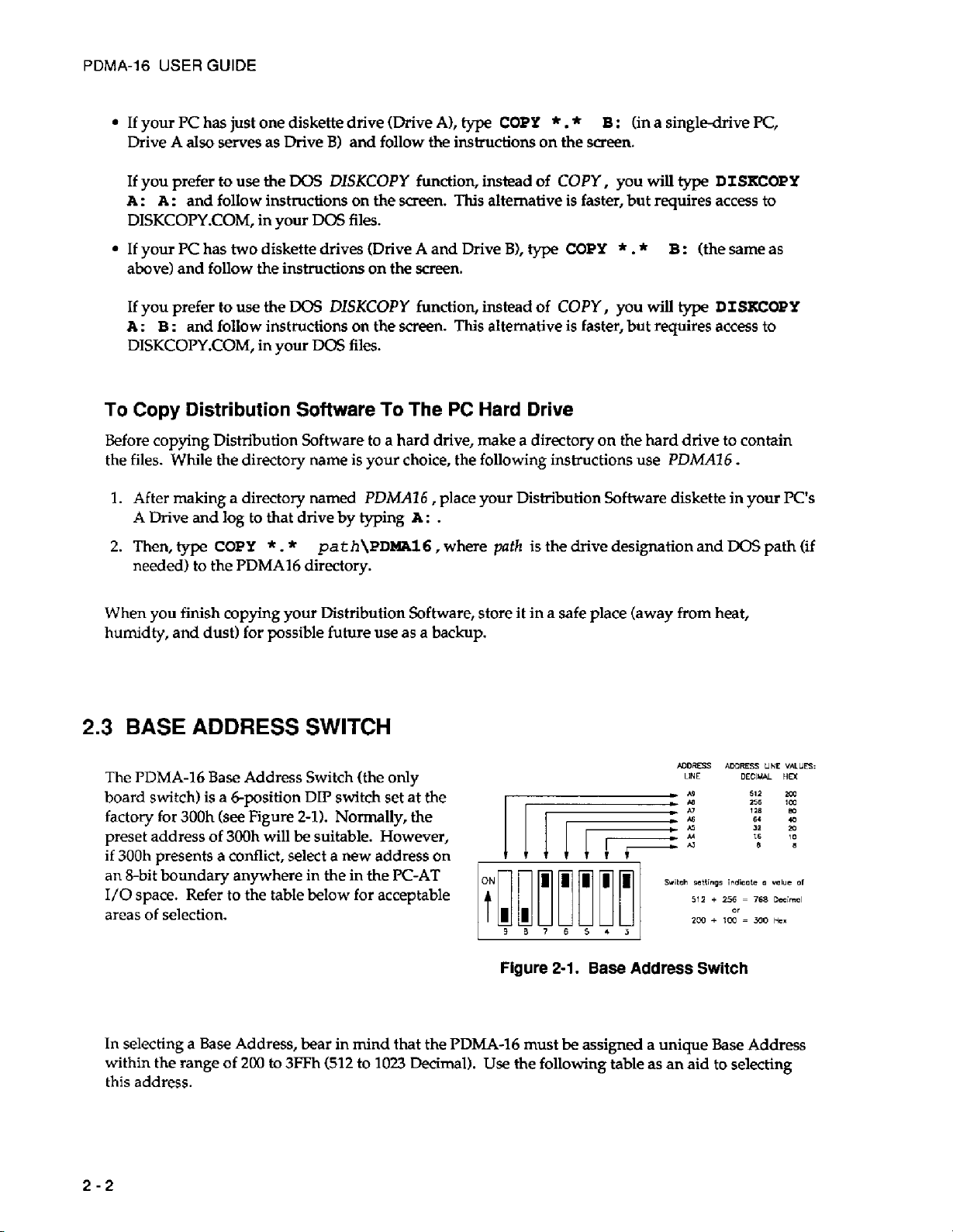
BASE ADDRESS SWITCH
The PDMA-16 Base Address Switch (the
board
switch)
factory for
preset address
if
300h
presents a conflict, select a new address
an
8-bit boundary anywhere in the in the
I/O
space. Refer
areas
of
In selecting a Base Address, bear in mind that the PDMA-16 must
within the
this address.
is
300h
of
selection.
range
a
&position
(see
Figure
300h will be suitable. However,
to
the table below for acceptable
of
200
to
DIP
2-11.
3FFh
switch set at the
Normally, the
(512 to
only
PC-AT
1023
on
Decimal).
Figure
Use
NDRSS
LINE
2-1.
Base
Address
be
assigned a unique Base Address
the following table as an aid
Switch
ADDRESS
DECIUAL HD:
to
selecting
UNE
VALUES:
2-2
Page 13
CHAPTER
2:
INSTALLATION
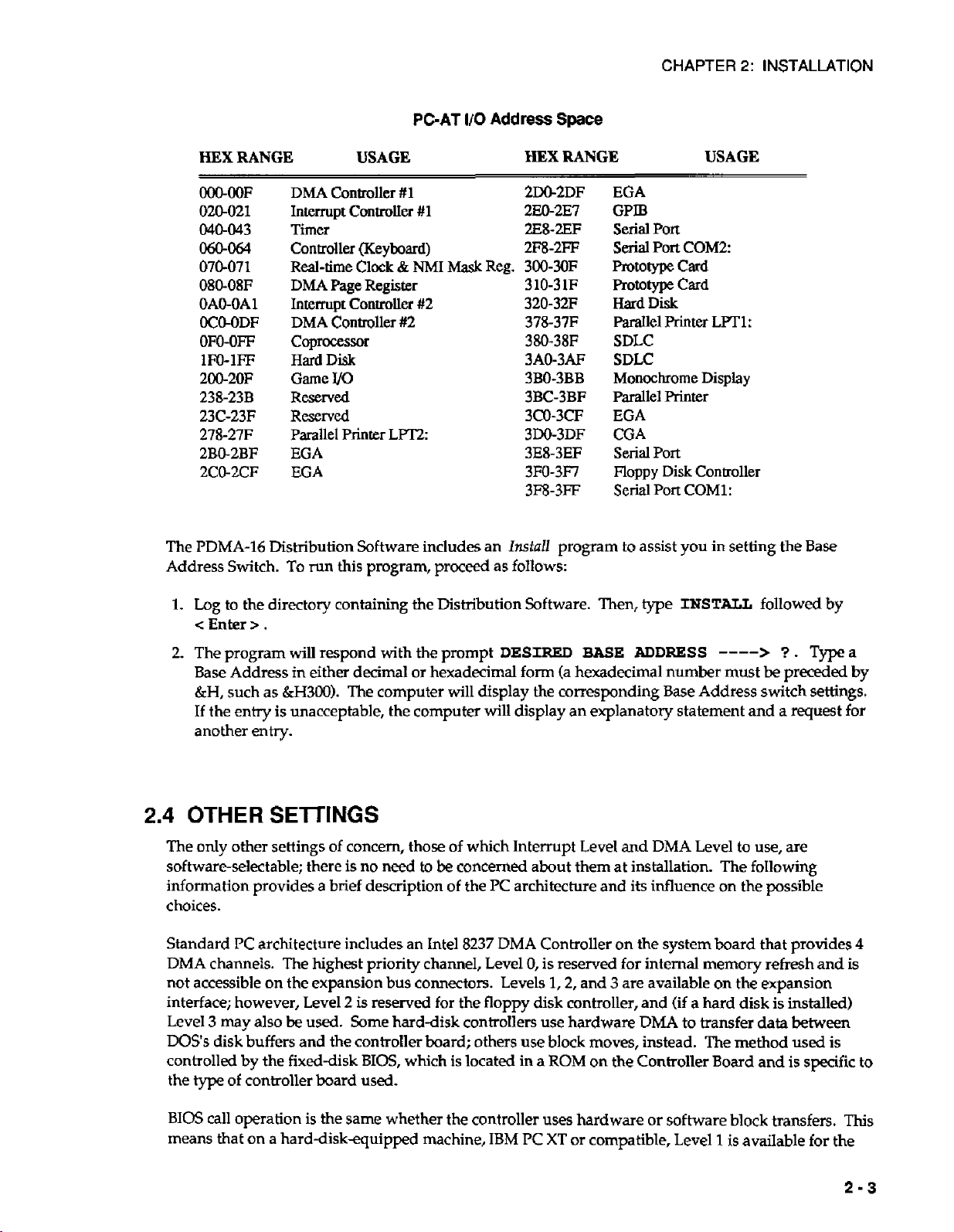
HEX RANGE USAGE
DMA
OOO-OOF
020-021
040-043
060-064
070-071
080-08F
OAO-OA1
OC@ODF
OM)-OFF
1m-IFF
200-2OF
238-23B
23C-23F
278-27F
2BO-2BF
2C0-2CF
The
PDMA-16
Address Switch.
Distribution Software includes an
Controller
Interrupt
Timer
Controller (Keyboard)
Real-time
DMA
Page
Intermpt
DMA
Controller
Coprocessor
Hard
Disk
UO
Game
RWXVed
RWXVed
Parallel
EGA
EGA
To
run this program, proceed as follows:
#1
ControlIer
Clock
&
Register
Controller
#2
Printer
LFT2
PGAT
#1
NMI
Mask
#2
I/O Address
HEX
2W2DF
2EO-2E7
2E8-2EF
2m-2FF
300-3OF
Reg.
310-3 1F
320-32F
378-3380-38F
3AO-3AF
3BO-3BB
3BC-3BF
3CO-3CF
3DO-3DF
3E8-3EF
3m-3F7
3F8-3FF
Install
Space
RANGE
EGA
GPIB
Serial
Port
Serial
Port
mtotypecard
prototype
Hard
Disk
ParaIlel
SDLC
SDLC
Monochrome Display
Parallel Printer
EGA
CGA
Serial
Port
Floppy
Serial
Port
program to assist
USAGE
COM2
Card
Printer
Disk
LFT
Controller
COM1:
you
in
1
:
setting the
Base
1.
Log
to the directory containing the Distribution Software. Then, type
<
Enter
>
.
2.
The program will respond with the prompt
Base Address
&H,
such as
If
the entry
another
2.4
OTHER
The only other settings of concern, those of which Interrupt Level and
softwareselectable; there
information provides
choices.
3
may
disk
type
of
PC
Standard
DMA channels. The highest priority channeI, Level
not accessible on the expansion bus connectors. Levels
interface; however, Level
Level
DOS’s
controlled by the fixed-disk
the
in
either decimal or hexadecimal form (a hexadecimal
&H300).
is
unacceptable, the computer
entry.
The computer will display the corresponding Base Address switch settings.
SElTINGS
is
no
need
to
a
brief description of the
architecture includes an Intel
2
is reserved for the floppy disk controller, and
also
be
used.
Some
hard-disk controllers use hardware
buffers
controller board
and the controller board; others
BIG,
which
used.
be
is
DESIRED
will
display an explanatory statement and a request
concerned about them at installation. The following
PC
architecture and its influence on the possible
8237
DMA
0,
use
located in a ROM on the Controller Board and is
BASE
Controller on the system board that provides
is reserved
1,2,
and 3 are available on the expansion
block
moves, instead. The method
ADDRESS
number
DMA
for
internal
(if
DMA
INSTALL
Level
memory
a hard disk
to transfer data between
---->
must
to
followed
?
.
Type
be
preceded by
use, are
refresh and
is
installed)
used
by
is
specific
a
for
4
is
to
BIOS
call operation is the same whether the controller uses hardware
means that on a harddiskequipped machine,
IBM
PC
XT
or
or
compatible, Level
software block
1
is
available
transfers.
for
This
the
2-3
Page 14

PDMA-16
USER
GUIDE
PDMA-16;
Levels
when a hard disk is included. Selection
the
PDMA-16
The
PDMA-16
Levels
Bits
4-6
It
is possible to operate more
placed at different
same interrupt and
Level
3
may
also
1
and 3 are both available.
Control Register.
may
also
generate interrupts
(2
thru
7).
Like
the
DMA
of the
PDMA-16's
1/0
Interrupt Control Register.
addresses. Since the interrupt and
DMA
channels may
be
available.
Also,
On
floppy-diskanly machines
the
IBM PC/AT
of
the
DMA
on
any
always
Level 1 or 3 is
of
the
available
level, the active Interrupt Level is
than
one
PDMA-16
in a single computer. In
DMA
be
shared
among boards as long as they are individually
has
Levels 1 and 3 available even
under
software
expansion-connector Interrupt
selected
this
channels employ tri-state drivers, the
enabled and disabled in sequence by the controlling software. If the boards are to
simultaneous
2.5
I/O
A
standard 37-pin,
I/O.
The mating connector is a standard, 37-pin
female
such
connections. Insulation displacement
readily available (for example,
manufacturers make equivalent
access connections with screw connectors,
manufacturer's
The
1/0
described in Figure
follow.
DMA
and interrupts,
they
must operate on different
CONNECTOR
D-type
as
an ITT/Cannon #DC37S for soldered
STA-U
Connector and its signal conductor functions are
2-2
Figure
2-2. Main
male connector is
used
for
all
D-type
(ff
Amp
parts.
at cable)
#745242-1).
If you wish to
use
types
Other
the
Universal Screw Connector Board.
and the table
I/O
of
functions that
Connector
are
IeveIs.
XFER
ACK.
XFER
ma.
INTERRUPT
A7
El6
OUT
IN
IN
(IBM
PC or compatible),
control by Bit 6 of
by
software control
case
boards should
perform
F-----.
37
'
36
35
34
33
32
31
30
'
29
28
27
26
25
24
23
4
22
21
20
>
A
DIR.
OUT
GND
GND
GND
CND
GND
GND
GND
B
DfR.
OUT
GND
GND
AUX.
3
OUT
AUX. 2 OUT
AUX.
1
OUT
TIMER
GATE
TIMER
OUT
POWER
1%
>
COMPUTER
using
be
IN
FROM
2-4
SIGNAL
NAME FUNCTION
INTERRUPT
XFER. REQ.
XFER.
ACK.
80
A0
IN
IN
OUT
-
B7
-
A7
This
is
a
positive or negative edge triggered intempt input.
edge
is
selected
A
positive
the
DMA
On
receipt
finished
data
is
on
mode.
Port
B
data
Port A data
I10
Signal
by
bit
edge
on
this
control
register
of
a
XFER.
the
byte
or
the
port(s)
(input/output)
(input/output)
Functions
DO
of
the
input initiates
=
0.
REQ.
the
word
transfer,
in
output
interrupt
a
XFER.
XFER.
mode,
control
DMA
ACK.
ACK.
or
that
register.
transfer
goes
returns
data
has
with
low.
been
The
slope
DMA
enabled
After
the
high
indicating
aansferred
of
8237
the
trigger
and
DMA
that
in
input
D3
of
has
valid
Page 15
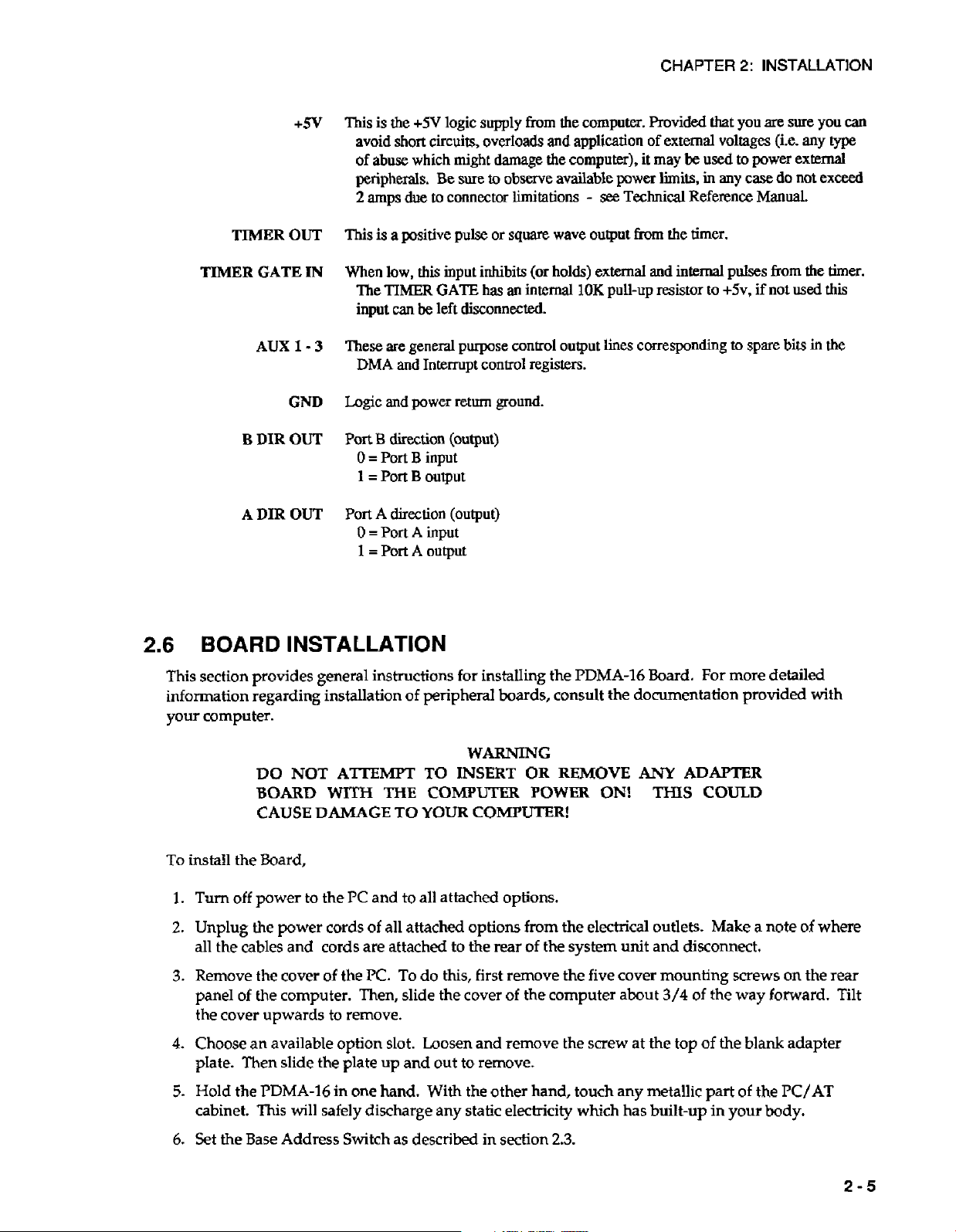
TIMER
TIMER
B
A
OUT
GATE
AUX
GND
DIR
OUT
DIR
OUT
+5V
IN
1
-
3
This
is
the
+5V
avoid
short
of
abuse which might
peripherals.
2
amps
due
This
is
a positive
When
low,
this
The
TIMER
input
can
be
These
are
general
DMA
and
Logic
and
power
Port
B
direction
0
=
Port
B
1
=
Port
B
Port
A
direction
0
=
Port
A
1
=
Port
A
logic supply from
circuits, overIoads
damage
Be
sure
to
observe available
to connector
pulse
input
GATE
left
disconnected.
purpose
Interrupt
return
(output)
input
output
(output)
input
output
limitations
or
square
inhibits
has
an
control
control
ground.
the
and
the
wave
(or
holds)
internal
output
registers.
computer.
application
computer),
power
-
see
Technical Reference
output from
external
1OK
pull-up
lines
corresponding
CHAPTER
Provided
of
external
it
may
be
limits,
the
and
internal
resistor
that
voltages
used
in
any
timer.
to
2:
INSTALLATION
you
are
(i.e. any
to
power
case
do
Manual.
pulses
from
+5v,
if not
to
spare
bits
sure
you
external
not
exceed
the
used
in
can
type
timer.
this
the
2.6
BOARD
This
section provides general instructions
information regarding installation of peripheral boards, consult the documentation provided
your computer.
To
install
1.
2.
3.
4.
5.
the
Turn
off
Unplug the power cords
all the cables and cords are attached to the rear
Remove the cover of the
panel
of
the cover upwards
Choose an available option slot. Loosen and remove the screw at
plate. Then slide the plate up and out
Hold the
cabinet.
INSTALLATION
for
instalIing the
WARNING
DO
NOT
BOARD
CAUSE
Board,
power to the
WITH
DAMAGE
ATEMTT
PC
and
of
TO
INSERT
THE
COMfuTER
TO
YOUR
to
all attached options.
all attached options from the electrical
COMPUTER!
OR REMOVE
of
PC. To
the
computer. Then, slide the cover
to
remove.
PDMA-16
This
in one hand. With the other hand, touch any metallic part
will safely discharge any static electricity which has built-up in your
do this, first remove the five cover mounting screws
of
the computer about
to
remove.
PDMA-16
Board. For more detailed
ANY
POWER
the system unit and disconnect.
ON!
THIS
outlets.
3/4
the
top
ADAPTER
COULD
Make a note
of the way forward. Tilt
of
the
blank adapter
of
the
body.
with
of
where
on
the rear
PC/AT
6.
Set
the Base Address Switch as described
in
sedion
2.3.
2-5
Page 16
PDMA-16
7.
Align the gold edge connector with the edge socket and the back adapter place with the adapter
plate screw. Gently press
8.
Replace the computer's cover.
the front
USER
GUIDE
of
the cover
the
board downward into the socket. Reinstall the adapter plate screw.
Tilt
the cover up and slide it onto the system's
is
under the rail along the front
of
the frame.
Install
base,
making
the mounting screws.
sure
9. Plug
in all cords and cables.
Turn
the power
to
the computer back on.
2-6
Page 17

CHAPTER
3
At the lowest level, the
these are the
languages have equivalent instructions (for example,
of
these functions
Although not demanding,
the devices, data format, and architecture
3.1
I/O
PDMA-16
space, as shown in the following table.
ADDRESS
I"Q0
MAP
boards
PDMA-16
and
usually
use
16
is
programmable via
OUT
X,Y
functions.
invoIves formatting data and dealing with absolute
this
type
of
programming requires that you have a
of
the PDMA-16.
consecutive addresses starting at the Base Address in the computer's
FUNCTION
REGISTER
I/O
(Input/Output)
Assembly
Language and
IN
AL,DX
and
STRUCTURES
most
OUT
instructions.
other high- level
DX,AL
in
1/0
addresses.
full
understanding
TYPE
In
BASIC,
Assembly).
1/0
Use
of
Base
Address4
Base
Address+l
Base
Address+:!
Base
Address+3
Base
Address4
Base
Address+S
Base
Address4
Base
Address+7
Note that addresses
3.2
PORTS
Port
A data corresponds one-for-one
transfers the Least Significant Byte and
transfers, Port
ports
A
and B can always
or
not they are involved in DMA transfers.
byte transfers are taking pIace through port
A
81
A
becomes
B
A
Port
B
Port
DMA
Interrupt
Counter
Counter
Counter
Counter Control
Counter
Base
the
default
be
written
Conaol
Control
0
1
2
Status
Address
with
Port
I/O
to
and read
+4
thru
+7
correspond to the
the data bus. When transferring
B
transfers the Most Significant Byte.
port
(you cannot use Port B for DMA byte transfers).
as
standard
Port
E
can
be
used
A.
1/0
ports
as a standard
ReaWrite
Read/Write
Reamrite
Read/Write
Read/Writ&
Read/write
Read/Write
Write
Read
8254
words
by
an
1/0
1/0
timer.
by
DMA,
For
Port
DMA byte
A
Both
instruction whether
port
while DMA
The
Port A data
Base+O
format
A7
is
as
follows:
A6
A5
A4
A3
A2
A1
A0
3-1
Page 18
PDMA-16
The
Port B data format
USER
GUIDE
is
as
follows
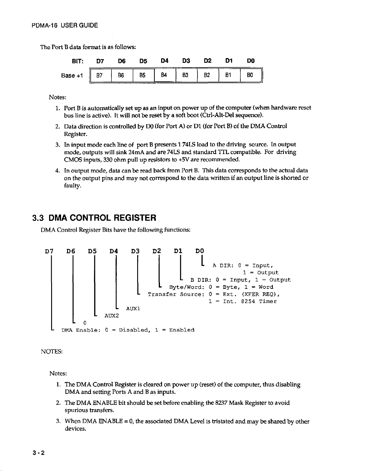
3.3
DMA
Base+1
B7
86
B5
EM
Notes:
1.
Port
B
is automatically
bus line
2.
Data direction is controlled
Register.
3.
In
mode, outputs
CMOS
4.
In output mode, data can
is
active).
input mode
inputs,
each
will
330
on the output pins and
set
up
It
wiU
not
line
of
sink
24mA
ohm pull
be
may
as
an input
be
rewt
by
W
port
B
and
up
resistors
read
not
correspond
by
(for
Port
presents
are
74LS
back
from
faulty.
DMA
CONTROL
REGISTER
Control Register Bits have the following functions:
I33
on
power up
a
soft
A)
1
74LS
and
to
+5V
Port
to
02
boot
(Ctrl-Alt-Del
or
Bl
(for
load
standard
81
of
the computer (when hardware reset
Port
3)
to
the driving source.
TTL
are recommended.
8.
This
data corresponds
the
data
written
I30
sequence).
of
the
DMA
Control
In
output
compatible. For driving
to
the
actual
if
an
output
line is shorted
data
or
I
NOTES:
Notes:
1.
2.
3.
D
DMh
The
DMA
The
D
0
Enable:
DMA
Control Register is cleared
and setting Ports A and B as inputs.
DMA
ENABLE bit should
spurious transfers.
When
DMA
ENABLE
devices.
D4
AUX2
0
=
D
AUXl
Disabled,
=
0,
the associated
B2
L
Transfer
1
=
on
be
set
before
D1
Byte/Word:
Enabled
power
DO
I
B
DIR:
Source:
up
(reset)
enabling
DMA
Level
0
=
0
=
0
=
1
=
of
the 8237
is
tristated
1
=
output
Input,
Byte,
Ext.
Int. 8254
1
1
=
(XFER
=
Output
Word
REQ),
Timer
the computer, thus disabling
Mask
Register
and
my
to
avoid
be
shared
by other
3-2
Page 19

4.
3.4
INTERRUPT
The
Interrupt
The
AUXl
brought
out
Control Register
and
AUX2
bits correspond
to
provide additional
to
unused
outputs
CONTROL REGISTER
bits
have the following functions:
on the
CHAPTER
bits.
For convenience, these have been
rear
connector.
3:
REGISTER STRUCTURES
D7
-
Notes:
D
-0
-0
IN'I
1.
The Interrupt
interrupts.
2.
The
INT
Register to avoid generation
3.
When
N
other devices.
Control
ENABLE
bit shouId
ENABLE = 0,
T
-
Am3
Register
is
cleared
be
set before enabling the
of
spurious interrupts.
on
the associated Interrupt
1
Slope:
00
=
External
01 = 8237
10
=
11
=
8254
8237
Terminal
Timer
Terminal
power-up (reset)
8E9
Level
is
Input
of
Interrupt
tristated
0
=
+
Edge,
1
=
-
Edge
the computer,
Controller
thus
Mask
disabling
and available for use by
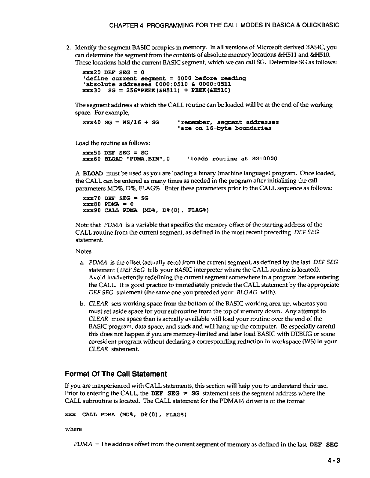
3.5
4.
The
Am3
bit corresponds to an unused bit.
provide an additional output on the rear connector.
8254
10
XTAL
CLOCK
i
5v
TIMER
MHZ
2
GATE
CLOCK
GATE
CLOCK
I14V
.
-.
1
OK
GATE
CLOCK
r----------~-~~--------------
0
0
1
I
1
2
2
Diagram
CLOCK
CLOCK
CLOCK
of
8254
8254
1N
16-BIT
IN
16-BIT
IN
16-BIT
connection
For
convenience,
TIMER COUNTER
COUNTER
DOWN
COUNTER
DOWN
COUNTER
DOWN
0
COUNTER
1
COUNTER
2
COUNTER
in
0
UT
PDMA-16.
it
has been
I
I
!
TO
I-
I
INTERNAL CIRCUITS
N.C.
brought
out
to
3-3
Page 20
PDMA-16
I/O
USER
locations
GUIDE
BASE
+4
capabilities and programming
adequate
for
programming, is supplied in Chapter
timing pulse generation
you,
accessible to
although
thru
and
+7
correspond to the
is
provided
its
connection
it
may
be
loaded and read
in
the
is
shown
8254
Intel
6.
Timer.
8254
Its
below.
for
A
fuIl
description
of
data sheet and a partial description,
use
in
the
PDMA-16
Note that Counter
timing
purposes.
is purely
2
is
the
not
8254
for
periodic
hardware
3-4
Page 21
CHAPTER
4
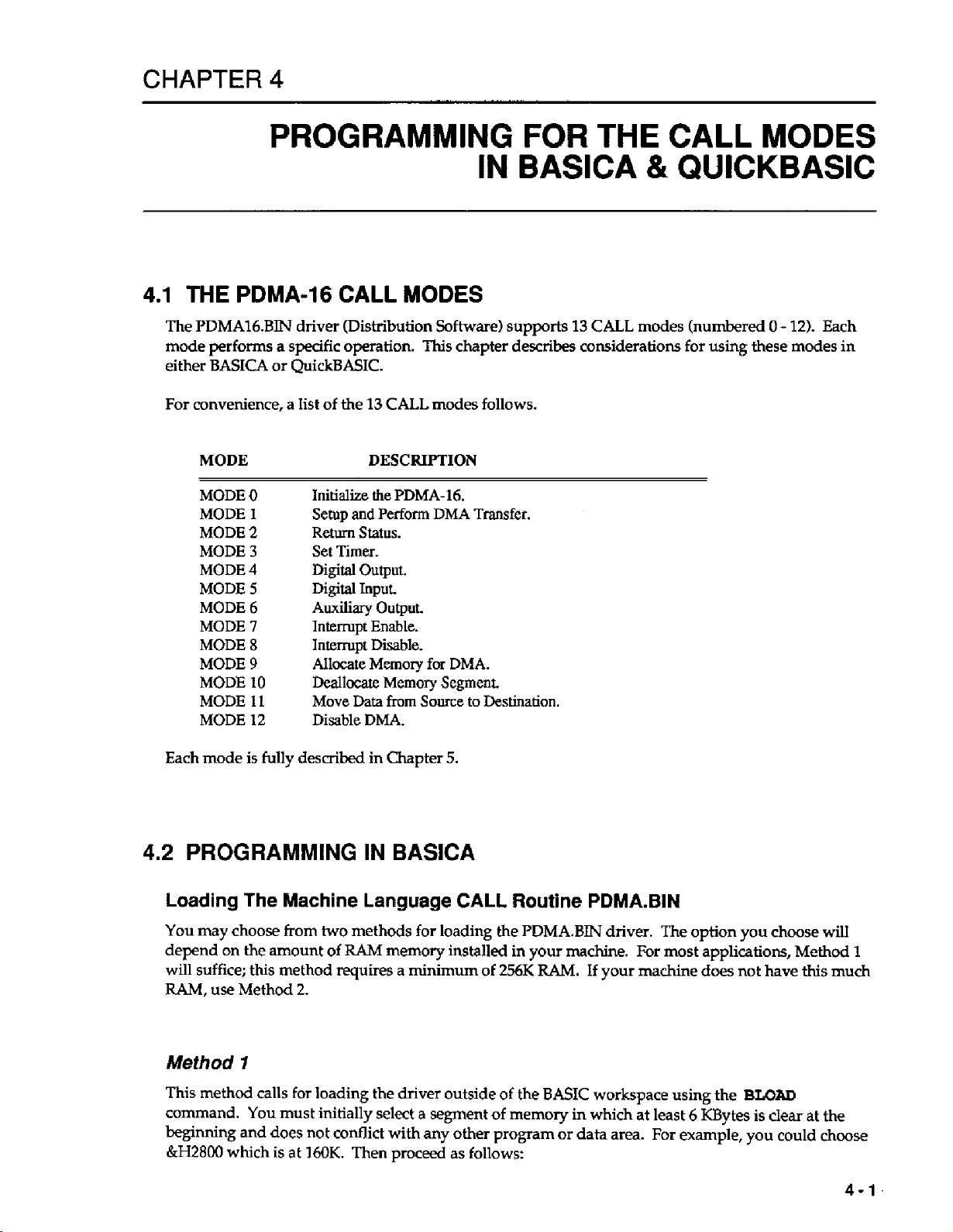
4.1
THE
The
PDMAldBIN
mode perfoms
either
BASICA
For
convenience, a Iist of
MODE DESCRIPTION
MODE
MODE
MODE
MODE
MODE
MODE
MODE
MODE
MODE
MODE
MODE
MODE
MODE
PROGRAMMING
PDMA-16
a
specific operation.
or
QuickBASIC.
0
1
2
3
4
5
6
7
8
9
10
11
12
CALL
driver (Distribution Software) supports
the
Initialize the
Setup
and
Return
Set
Timer.
Digital
Digital
Auxiliary
Interrupt
Interrupt
Allocate Memory
Deallocate Memory Segment.
Move Data
Disable
13
CALL
PDMA-16.
Perform
Status.
Output.
Input
Output.
Enable.
Disable.
from
DMA.
MODES
This
modes follows.
DMA
for
Source
IN
chapter
Transfer.
DMA.
to
Destination.
FOR
THE
BASICA
13
CALL
describes
considerations for using these modes in
CALL
&
QUICKBASIC
modes (numbered
MODES
0
-
12).
Each
Each mode is
4.2
PROGRAMMING
fully
described in Chapter
IN
BASICA
Loading The Machine Language
You
may
choose
depend
will suffice;
RAM,
on
use Method
Method
This
method
command. You must initially select a segment
beginning and
&H2800
which
from
two
methods for loading the
the
amount
this
method requires a minimum
2.
of
RAM
memory
I
calls
for
loading the driver outside
does
not conflict with any other program
is
at
160K.
Then proceed as follows:
5.
CALL
installed
of
of
Routine
PDMA.BIN
in
your
256K
RAM.
of
the
memory in which
machine.
BASIC
or
data area.
PDMA.BIN
If
your
workspace using
driver. The option you choose
For
most applications, Method
machine does not have
the
BLOAD
at
least 6 KBytes
For
example,
is
you
this
clear
at
could choose
will
1
much
the
4-1
Page 22
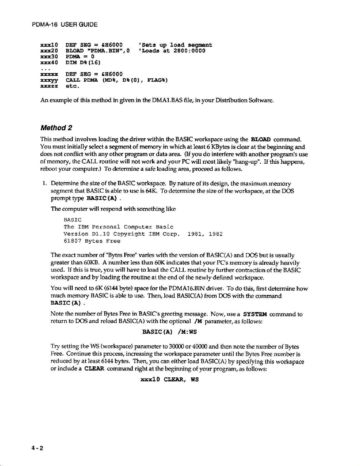
PDMA-16
USER
GUIDE
rxxlo
xxx20
-30
-40
DEF
SEG
BLOAD
PDMA
DIM
D%(16)
=
hH6OQO
nPDMA.BINn,O
=
0
'Sets
'Loads
up
load
at
28OQ:QOOQ
...
xxxxx
xxqy
xxxzz
An
Method
This method involves loading
You
does not conflict with
of
memory, the
reboot your computer.)
1.
DEF
SEE
=
CALL
PDMA
etc.
example of this method in given
&H6000
(MD%,
D%(o),
in
the
FLAG%)
DMA1.BAS
2
the
driver within the
must initially select a segment of memory in which at least
any
other
CALL
routine will not work and your K will most likely "hang-up". If
To
Determine the size of the
segment that
prompt
type
BASIC
BASIC
is able
(A)
program
determine a safe loading area, proceed
BASIC
to
use
.
or
data area.
workspace.
is
64K.
The computer will respond with something like
BASIC
By
To
determine the
segment
fiIe, in your Distribution Software.
workspace using the
6
Of
you
do
nature
of
its design, the
size
KBytes
is
interfere
as
follows.
of
the workspace, at the
BLOAD
clear at the
with
another program's use
maximum
command.
beginning
this
and
happens,
memory
DOS
BASIC
The
IBM
Personal
Version
61807
D1.10
Bytes
The exact number of "Bytes
greater
used.
workspace and
You
much memory
BASIC(A)
Note the number
return to
Try
than
6OKB.
If
this is true, you will have to load the
will need to
A
by
loading the routine at the end
6K
(6144
BASIC
.
of
Bytes Free in
Dos
and reload
setting the
WS
(workspace) parameter
Computer
Copyright
Free
Free"
varies with the version of
number Iess than
byte) space for the
is
able to
use.
BASIC's
BASIC(A)
BASIC
Basic
IBM
Corp.
6OK
indicates that
CALL
of
the newly defined workspace.
PDMAl6.BIN
Then, load
BASIC(A1
greeting message.
with the optional
(A)
/M:WS
to
3oooO
or
1981, 1982
BASIC(A1
your
Pc's
routine
by
further contraction
driver.
from
DOS
Now,
/M
parameter, as follows:
4oooO
and then note the
and
Dos
memory is already heavily
To
do this, first determine how
with the command
use
a
SYSTEM
Free. Continue this process, increasing the workspace parameter until the Bytes
reduced by at least
or inciude a
CLEAR
6144
bytes. Then, you can either load
command right at the beginning of
XXxlO
CLEAR,
BASIUA)
your
ws
by
specifying
program, as follows:
but
is usually
of
the
command
number
Free
of
number
this workspace
BASIC
to
Bytes
is
4-2
Page 23
2.
Identify the segment
CHAPTER 4 PROGRAMMING
BASIC
occupies in memory. In
FOR
THE CALL
all
MODES
versions of Microsoft derived BASIC,
can determine the segment from the contents of absolute memory locations
These locations hold the current BASIC segment, which we can call
ru20
'define current segment
'absolute
xu30
DEF SEG
SG
=
0
addresses 0000:0510 & 0000:0511
=
256*PEEK(&H511) + PEEK(LH510)
=
0000
before reading
IN
BASICA & QUICKBASIC
SG.
&mll
Determine
and
SG
you
&H510.
as follows:
The segment address at
For
space.
xxxrl0
Load
srr50
xu60
A
BLOAD
example,
SG
=
the
routine as follows:
DEF SEG
BLOAD
must
be
the CALL canbe entered as many times
parameters MD%, D%,
-70
-80
-90
Note that
DEF
PDMA
CALL
PDMA
SEG
which
WS/lS
=
"PDMA.
used
FLAG%.
=
=
0
PDMA
the CALL routine
+
SG
SG
BIN",
as
you are loading a binary (machine language) program. Once loaded,
'ratuxrhr,
'are
0 'loads
as
Enter these parameters prior to the
SG
(MD%,
D%(O),
FL?iG%)
can
be
loaded will
on
segment addresses
16-byte
routine
boundaries
needed in the program after initializing the
is a variable that specifies the memory offset
be
at the end
at
1G:OOOO
CALL
of
the starting address
sequence as follows:
CALL routine from the current segment, as defined in the most recent preceding
statement.
Notes
a.
PDMA
statement ( DEF
Avoid inadvertently redefining the current segment somewhere in
the
DEF SEG
is the offset (actually zero)
SEG
tells
CALL.
It
is
good
practice to immediately precede the CALL statement by the appropriate
your
from
BASIC interpreter where
statement (the same one you preceded your
the current segment, as defined by the last
the
CALL routine is located).
a
program
BLOAD
with).
of
the working
call
of
DEF
SEG
DEF
before
the
SEG
entering
CLEAR
b.
sets working
space
from the bottom
must set aside space for your subroutine
CLEAR
more space than
is
actually available will load
BASIC program, data space, and stack and will hang up the computer.
this
does
not happen
if
you are memory-limited and later load BASIC with DEBUG or
coresident program without declaring a corresponding reduction in workspace
CLEAR
Format
Of
If you are inexperienced with CALL statements,
Prior
to
entering the
CALL subroutine
xxx
CALL
statement.
The
is
PDMA
Call
Statement
CALL,
located.
(MD%,
this
the
DEF
SEG
=
SG
The
CALL statement for the PDMA16 driver
D%(O),
FLAG%)
where
PDMA = The address offset from the current segment
of
the
from
the
BASIC
top
working area
of
memory down. Any attempt to
your
routine over the end
up,
whereas you
of
Be
especially careful
the
(WS)
section
Statement sets the segment address where the
will
help you
of
memory as defined in the Jast
to
understand their
is
of
the format
DEF
some
in
use.
your
SEG
4-3
Page 24
PDMA-16
statement.
USER
GUIDE
MD%
D%
FLAG%
In executing
BASIC's stack. The CALL routine unloads
variables in BASICS data space
rules to remember when using the
1.
2.
3.
=
Call parameter representing the
=
Call parameterb) representing the Data Variable(s).
=
Call parameter representing
the
CALL, the addresses of the variables (pointers) are
so
data can
CALL
The CALL parameters must always
recognize the names of the variables, just their Iocations . For example,
PDMA
number,
All parameters must be defined as integer
checking on the variable
perform
Do not
statement. Forexample,
will produce a syntax error.
(D%(O),
MD%, FLAG%)
MD%
correctly.
perform
any arithmetic functions
as the data, etc.
type.
CALL
is used, the CALL routine would interpret
If
you use the wrong variable
PDMA
Mode
Number.
Errors.
these
pointers
be
exchanged with them. There are several important
statement:
be
written in the correct order. The subroutine does
type
from
the stack and
variables. The CALL does not
type,
within
(MD%
the parameter list brackets of the CALL
+
2,
D%
(0)
passed
in the sequence written to
uses
them
to locate the
if
the line
D%(O)
wcxxll
as the MODE
perform
the CALL function will not
*
8,
FLAG%)
isillegaland
not
CALL
any error
4.
Do
not
use
constants for any
2,
FLAG%)
5.
You
may assign any name you wish
6.
Declare all variables before executing the CALL. If you do not, the simple variables
declared by default on execution but array variabIes cannot be dimensioned by default and must
be dimensioned before the CALL to
MODES
reason,
array from
Likewise, any
can name any number of different integer data arrays for output and input. It is permissible to
dimension arrays with more elements than will
unchanged and for example could
Execution
The execution times
operations that process data in your program may also delay your overall throughput. One solution
which would improve the speed of your program
.
of
the CALL routine require multiple items of data to
D%(O)
is
the
position
of
Times
of
specified
the
other CALL parameters
-
Compiled BASIC
most modes of the PDMA-16 are limited by the software. Additionally,
of
the parameters. For example, this is illegal:
to
pass
as the data variable
of
its initial element.
be
used
CAU
the variables.
data correctly if used as a CALL parameter. Most
be
passed in an array. For
so
that the CALL routine can locate the whole
may
be
integer array variables if requid, and you
be
used
by the CALL. Unused elements will be
for
tagging data with time, date,
is
to
use
compiled
SASIC
or
or QuickBASIC.
PDMA
will
other information.
(7,
be
this
other
4.3
PROGRAMMING
This section contains information for users wishing to write data acquisition programs in QuickBASIC
(QB).
In addition to the information provided in this section, you may want to consult the
QuickBASIC example programs in the
4-4
IN
QUICKBASIC
Distribution
Software.
Page 25
CHAPTER
4
PROGRAMMING
FOR
THE
CALL
MODES
IN
BASICA
B
QUICKBASIC
Loading
A
QuickBASIC program will
Software contains the following linkable driver/Iibraries:
Load the PDMAQB45.QLB
the
To
load an application program (such as
Library and EXG3.BAS together by typing
Use PDMAQBX.QLB in an identical manner when using the QuickBASIC Extended Enviroment
(QBX)
The
Program
PDMAQB45.QLB
PDMAQBX.QLB
PDMAQB45,LIB
/L
switch,
Version
as
7.0.
follows:
have
Load
4.5
Load
LINK
Quick
QB
to
make calls to an external driver/library.
this
Quick Library into
or
lower,
this
Quick
Library
this
library
to
Library into
/L
PDLdAQB45.
EXG3.BAS)
your
QB
your
QuickBASIC
into
your
QuickBASIC
stand-alone QuickBASIC
the
QB environment from the
along
with
/L
PDMAQB45
Your
Integrated
Extended
Environment Version
Environment Version
program.
Dos
the Quick Library,
EXG3
.
Distribution
command Iine using
you
load the Quick
7.0
Declaring The Driver
Before you
application. Make this declaration by inserting the following at the beginning of your program:
where
NOTE:
Format
Unlike BASICA, the first and third parameters in
parameter is passed
represent the offset of the command integer array.
function
use
the driver/library,
DECLARE
QBPDMA
Of
as
follows:
is
All subroutine DECLARES in your program
allocated.
segment. All arrays
QuickBASIC assumes $STATIC data (Default data segment) unless otherwise specified.
The Call Statement
SW
the common entry point to the driver/library
$DYNAMIC
as a
pointer.
you
must declare the CALL label to make it known to your
QBPDMA
used
This
(MODE%,
BWAL
dunmy%,
for
MUST
data
is
allocated space
for
data acquisition
QB
are passed
arrangement is necessary because
To
pass the actual offset,
in
must
be
the
FAR
be
as
variables while the second
FLAG%)
driver modes.
before any
heap, outside the default data
declared as $DYNAMIC;
$DYNAMIC
the
second parameter
use
the
VARPTR
arrays are
must
where
MD%
is the Mode number,
4-5
Page 26
PDMA-16
USER
GUIDE
D%(N)
The VARPTR function returns the address
driver uses that value as a pointer
D%
is declared as a $STATIC array since it must reside in the default data segemnet in order to
relative to
the
QB
data segment, as required by the driver. Since
external driver, declare this parameter as an inter-module global variable,
D;M
D%(16)
COMMON SHARED D%
The
COMMON
module level
makes this variable visible between modules, and
makes
it
may declare any large
RI&d
$DYNAMIC
DIM
DMA%
(10000)
is the parameter array, and FLAG% returns detected errors.
()
known
$DYNAMIC
globaIly
of
D%(O),
to
the first element
in
this module.
which
of
our
After
you
pass
command integer array
declaring all your $STATIC variable, you
arrays for DMA data acquisition.
D%
the
as a
value
is
passed
as
SHARED
to
the driver. The
D%.
to and returned by the
folIows:
statement at the
be
NOTE:
All
$DYNAMIC
data declaration must occur
statements in your program.
flreceed
all
executablestafemmnts
AFIER
If
you get the
,
double check the order
QB
error
all
COMMON
$DYNAMIC declarations.
See
Section
Language Reference Manual
To
summarize, your program header should
2.5
($STATIC
and
$DYNAMIC
for
Arrays) and
a detailed discussion
look
as
(COMMON
of
the
factors
follows:
...
DECLARE
SUB
QBPDMA
(MODE%,
BWAL
dummy%,
FLAG%)
...
DIM
D%(16)
COMMON
k&i
DIM
SHARED
$DYMIMIC
DMA%
(10000)
D%
()
Parameter
I
DMA array
Array
in
for
FAR
...
Refer
to
the
QB
example programs (Distribution Software)
the
array
VARSEG
DMA%O
and
is a "FAR"
VARPTR.
Your
address
(32-bitsland
PDMA-16
may
driver/library
addresses, allowing you to avoid specifying absolute addresses as in
for
more detail.
be
determined by using the built-in operators
(.UB
or
.QLB)
COMMON
of
DECLARES COMMONS and
and DECLARE
and
DECLARE
must
statement) in the QuickBASIC
that determine array
mode
Heap
CALLS
Note
that the address of
is designed
types.
to
accept 32-bit
BASIC.
4-6
D%(l)
=
5000H
Page 27
CHAPTER 4 PROGRAMMING
FOR
THE
CALL
MODES
IN BASlCA & QUlCKBASlC
Instead, when passing
segment" and supply
FAR
pointers to QB,
the
FAR
specify
pointer's segment
elements. The following is an example of how
that the array
DSiO)
D%(1)
D%(2)
D%(3)
D%(4)
D%(5)
DM&%
(10000)
=
10000
=
0
=
1
=
0
=
VARPTR(DMA%(O))
=
VAFSEG(DMA%(O))
is
previously declared in the $DYNAMIC area,
'Sample
'flag
'internal
single
'Offset of
'Segment
...
A
final note on arrays. If you
should
be
declared as $DYNAMIC . The
dimensional structure. The
Making
There
Executable
are
two ways to create a stand-alone QuickBasic program that
command line:
wish
to erase and redimension an array during program execution, it
ERASE
statement
Programs
REDIM
-1
where you
and
offset in unused
this
is accomplished for the DMA Mode
count
to
look
clock
cycle
DMA%(O)
of
DMA%(O)
for
normally
D%O
Seg:ofs
specify
the "memory
parameter array
as
described
below!
1.
statement can now change the size but not the
is
not necessary.
is
executable from the
Assume
above.
DOS
1.
From within the
2.
From the
making
When
From
wifhin fhe
To
make an executable
1.
Invoke the environment, as follows:
QB
Dos
/L
QB
(QBX)
command line.
a stand-alone executable, you neec the
QB
Environment
from
the
PDMAQB4.5
or
QBX
/L PDMAQBX
2.
Select
the Run menu item.
3.
Select
the Make
4.
Select Produce: (*D) Stand-Alone
EXE
File
...
environment.
QB
Environment, use
QBDEMO
QBDEMO
from the Run menu.
EXE
File.
P32QB45.
the
following
'
fox
QB
for
QB
Ver
driver/library.
sequence:
up
Ver
4.5
7.0
5.
Select the < Make
This
sequence produces a standalone QBDEMO.EXE that
alternative,
you
may
EXE
and Exit > option.
use
the following procedure:
does
not require run-time support. As an
4-7
Page 28
PDMA-16
2.
3.
4.
This sequence produces a program QBDEMO.EXE that requires the run-time support program
BRUN45.EXE.
From
To
USER
1.
SeIect the Run menu item.
Select
Select Produce: (+D)
Select the <Make
the
compile QB programs from the
GUIDE
the Make
To
DOS
command
EXE
File.,.
EXE
EXE
and
run either
Line
from
the
Requiring
Exit>
option.
type
of
executable program,
DOS
Run
menu.
BRUN45.EXE.
type:
QBDEaao
command line, use the following command sequence
.
m
Bc
/e
/o
QSDEMO-BAS;
QBDEMO,
not
be
given in the
,
,
PDMAQB45
BCOM45.LIB
LINK
LIB;
line.
library
This
to
be
placed in the object module,
sequence wiIl produce a standalone
The
/o
option causes references to the
library response
executable.
LINK
need
from
so
the
As
an alternative,
The absence of the
placed in the object module,
produces an executable program that requires
the current directory at the time the program
Note that
in a subdirectory named
variable
To run either
The
You
inserting
the
“LIB+
Software
must declare the
the
type
EC
QBDEMO.BAS;
LINK
Compiler and Linker
(+SET
type
Driver
following at the beginning of your program:
DECLARE
QBDEMO,,,PDMAQBIS.LIB;
/o
option in
\BIN,
LIB=+
of
executabIe program,
CALL
CALL
the
compiler line causes references to the
so
the library response need not
in
expect
and
your
AUTOEXECBAT.)
to
to
find Libraries in the directory named by the environment
type
Label
label
to make it known
SUB
QBPDMA
(MD%,
be
given in
BRUN45.EXE
is
executed.
find the necessary executables
QBDEMO
to
BWAL
to
be
.
your application; make
PARAMS%,
the
in a subdirectory named
BRTJN45.LIB
LINK
line.
(BCEXE,
this
FIAG%)
LINK.EXE,
declaration by
library to
This
sequence
\BIN
be
or
etc..)
in
Note that all subroutine
are allocated. $DYNAMIC
data segment.
assumes
4-8
All
$STATIC
DECLARES
data
arrays used for data acquisition must
data (Default data segment) unless otherwise specified.
in your program
is
data that is allocated
MUST
space
be
declared as
be
in
made
the
before
FAR
$DYNAMIC;
any
$DYNAMIC
heap,
outside the default
arrays
QuickBasic
Page 29
The
Call
Parameters
CHAPTER
PROGRAMMING
4
FOR
THE
CALL
MODES
IN
BASICA & QUICKBASIC
Declare the mode call parameter array
DIM
D%
(9)
By
making the array
For example,
180
MD%
=
190
FLAG%
200
D%(O)
210
D%(1)
220
D%(2) = 7
230
D%(3)
240
CALL
250
Linking
IF
FLAG%
To
QBPDMA(MD%,
The
C0-N
to
initialize your
0
=
0
=
&€I300
=
3
=
1
<>
Driver
SBARED
COMMON
PDMA-16
VAF@TR(D%(O)),
0
THEN
PRINT
interface
D%(10)
D%
()
SHARED,
board,
"MODE
Module
as
follows:
other modules
use
MODE
'initialize
'declare
'Card
'DMA
l1NTERRUPT
'WORD
0
error
BASE
LEVEL
MODE
FLAG%)
Error
ADDRESS
LEVEL
#
and
subroutins can use it.
0
as follows:
mode
variable
";
FLAG%
The QuickBASIC Interface consists three separate Modules:
PDMAQB45.QLB Use when you load the QuickBASIC Enviroment Version
run
your
load
program from within
this
Quick Library
into
the
Environment (no
QuickBASIC,
as
foIlows:
EXE
envolved here).
:
STOP
4.5
Use
the
and
/L
you
plan
switch
to
to
QB
/L
PDUQB45
This
PDMAQBX.QLB
Extended Environment Version
is identical to PDMAQJ345.QLB except that it
7.0
(QBX).
QuickBASIC, as follows:
QBX /L
PDMAQBX
PDMAQB45.LIB Link to this library when
your
QuickBASIC
compiler and linker
PDMAQBXUB
your QuickBASIC
compiler and linker
(4.5)
source.
as
follows:
BC
your-program.
LINK
your-program,,,PDMAQB45.LIB;
Link to this library when
(7.0)
source.
as
follows:
Bc
your-program.bas
LINK
your-program,,,PDMAQBX.LIB;
To
create
such
bas
/o;
To
create such a program, use BC and
10;
your-program
is
designed for
Use the
/L
switch to load this Quick Library into
your-program
you
want
to
make a standalone
a program, use BC and LINK the QuickBASIC
you
want to make a stand-alone
LINK
EXE
program
EXE
program
the
QuickBASIC
QuickBASIC
from
from
4-9
Page 30
PDMA-16
USER
GUIDE
NOTE:
4.4
EXAMPLE
The Distribution Software contains several example
and examination. For example,
and
perform
use
the driver; it shows what is involved
how
much the driver simplifies programming.
compile then load with
memory. BASDEMO.BAS is not executable
The remaining BASIC programs are
TIMERBAS
STATUS.BAS
INBAS
All $DYNAMIC data declaration must
statements in your program. If
preceed
$DYNAMIC declarations.
DMA transfers.
readsports.
all
executable
BASIC
sets
the
returns the status.
PROGRAMS
DMA2.RAS
PDMABAS.LIB
timer
to
statemenfs
DMALBAS
as
any
performs
with
;it
uses
follows:
rate.
,
occur
after all COMMON and
you
get the
double
shows how to Ioad
handling the
BASD€MO.BAS
Mode
from
within the
QB
error
check
the
BASICA
the same functions
1/0
9
to
allocate memory and Mode
DECLARE
COMMON
order of
programs that are commented for listing
BASICA
all
PDMA.BIN,
directly through
is
an example program that
environment.
and
DECLARE
DELCARE,
initialize the
as
DMA1.BAS but does not
COMMON,
BASIC,
10
PDMA-16,
and
to deallocate
must
it
shows
you
and
may
0UT.BAS
.
IhT.BAS
writes to the
enables and
ports.
disables
interrupts.
...
4-10
Page 31

CHAPTER
5
5.1
OVERVIEW
This
chapter details each of the
Software) supports these
The particulars
exit, and a typical example of a
A
list
of
the
MODE
MODE
MODE
MODE
MODE
MODE
MODE
MODE
MODE
MODE
MODE
MODE
MODE
MODE
13
0
1
2
3
4
5
6
7
8
9
10
11
12
for
each mode include a description, data required for entry,
MODE
Calls
Initialize
Setup
Return
Set
Digital
Digital
AuxiIiary Output.
Set
Disable Interrupt.
Allocate
Deallocate
Move
Disable
13
PDMA-16 MODE
modes
(numbered
program
is
as follows:
DESCRXPTION
the
PDMA-16 Driver
and
Perform
Status
of
Timer
Rate.
Output.
Input
Up
and
Enable Interrupt.
Memory
Memory
Data
from
DMA.
entry.
DMA
DMA
Transfer.
for
DMA.
Segment
Source
0
-
121,
&
Transfer.
to
Destination.
THE
Calls.
The
PDMA.BIN
and each performs a specific operation.
Check
Hardware.
MODE
driver (Distribution
data
CALLS
to
be
expected upon
5.2
MODE
0:
INITIALIZE THE PDMA-16 DRIVER & CHECK
Description:
MODE
other
Level
16's A and
The Base
not
entry to the
sufficient to detect the presence
detected (absent board, wrong
0
initializes the driver and
MODEs.
for
interrupts, and the desired
I/O
an
Error
Initializing checks and stores
B
Ports
will
appear as a
Address
Exit
CALL.
#3
will
A
is checked
short
PDMA-16
16-
to
occur.
If
OK,
read/write test
or
absence
Base
hardware
the
DMA
Level. This
or
8-bit
peripheral
be
in the legal range
the Base
1/0
Address),
is
of
1/0
made
the
and
PDMA-16's
MODE
for
of
256
Address
to
some
board
at the
Error
#4
HARDWARE
must
be executed before
Base
1/0
Address, the desired Interrupt
also determines whether
normal
is
of
(Hardware
-
100s
stored
the
PDMA-16
specified
I/O.
(1OOh
for
use by other
1/0
Error)
-
3FOh) for the PC/AT.
internal register; it is
Address.
is returned,
using
the
PDMA-
MODEs
If
no
board
any
onre-
of the
If
is
5-
1
Page 32

PDMA-16
If
select
USER
GUIDE
initialization is successful,
any
other
MODE
before
any
other MODE may
performing
invalid DMA Level number or interrupt level
Entry
Data:
be
selected on subsequent
initidking
is
selected, Errors
MODE 0 will
#5
or
give
#6
CALLS.
rise
to
are
returned.
error
Trying
#
1
+
If
to
an
D%(U
Exit
Data:
D%(O)
Programming
A
typical start
Example:
for
D%(O)
D%(l)
D%(2)
D%(3)
thru
D%(6)
thru
D%(6) = Unchanged.
FLAG%
a
program
=
Base
Selected
=
Selected
=
=
Selects
=
Not
=
0
initializing sequence
I/O
Address
DMA
of
PDMA-16,
Level; 1 and
Interrupt Level;
port
MODE;
used,
value irrelevant.
if
OK;
otherwise:
1
if
MODE Number
3
if Base Address
4
if
hardware
5
if DMA
8
if Interrupt Level illegal.
12
if
Level
Byte/Word
0
=
<
<
lOOh
error, no
illegal.
MODE specifier
would
3
2
-
Byte
0
or
or
board,
be
as
range
are
valid.
7
are valid.
I/O,
1
z
12.
>
3FOh.
incorrect
follows:
100-3FOh.
=
Word
D%(3)
I/O
not
I/O.
address,
0
or
1.
100
DEF
SEG
=
110
120
130
140
150
160
170
180
190
200
210
220
5.3
BLOAD
PDMA
MD%
DIM D%(6)
FLAG%
D%(O)
D%(1)
D%(2)
D%(3)
CALL
=
=
PDMA
IF
FLAG%<>O
'continue
MODE
&€I4000
"PDMA.BIN",
0
0
=
0
=
&I3300
=
3
=
7
=
1
(MD%,
THEN
program
1
:
SET
UP
0
D%(O),
PRINT
&
PERFORM
FLAG%)
''Error
in initializing
'segment
'load it at
'declare
'select
'declare data array
'Base
'DMA
'Interrupt
'wordMODE
'initialize
to load
zero
variables
initialization
Address
Level
3
Level
-
#
DMA
TRANSFER
offset
=
16
"
;
FLAG3
driver
300
7
bit
Description:
MODE 3 sets
transfer using Bytes or Words. Using Bytes, the DMA hardware works through Port
remains open for programmed
DMA
uses both Ports A and
Significant.
up
both the
8237
DMA
I/O,
B;
Port A transfers
Controller and the PDMA-16 for an input or output DMA
and
MODE
1
will not disturb its configuration. In Word
the
Less
Significant Byte and Port 6 the More
hex.
1/0
:
STOP
A,
while
Port
Mode,
B
The DMA setup, which is performed
5-2
by
the driver, involves the following steps:
Page 33

CHAPTER
1.
Disable any
2.
Check data
3.
Check for a page wraparound problem, which can occur if for example
40,000
pages of
incrementing the Page Register from the
Instead,
DMA
transfer already in progress.
for
valid ranges.
bytes starting at an offset
64
Kbytes out
DMA
will continue at the beginning of the same
of
the memory. The
of
32,COO
in a page. The 8-bit
PC/AT
8237 DMA
you
DMA
Page Register selects 1 of
system
board hardware
Controllers when the end
page
and
may
overwrite
data memory. This condition of page wraparound is checked before enabling the
operation.
4.
The next step is to work out the correct control byte for the
5.
The
MODE,
Initial Address, and Byte Count Registers of the appropriate
PDMA-16 DMA
DMA
are then loaded.
6.
The timer
fixed
7.
The
8.
The timer
is
halted prior
to
delay (corresponding to
8237s
Mask Register is enabled,
is
brought
up
to
enabling the DMA channel
the
timer
pulse
rate) after setup.
its
correct
opening
speed.
the DMA channel.
so
that
the first transfer always occurs a
5:
THE
MODE
want to transfer
is
not capable of
of
a page
is
reached.
program
DMA
Control Register.
level
of
the
CALLS
16
or
8237s
The setup procedure
rest of the following
2.
Entry
Data:
Exit
Data:
D%(O)
thru
is
followed by a return
program
D%(O)
D%(U
D%(2)
D%(3)
D%(4)
D%(5) =
D%(6)
D%(6)
FLAG%
executes. If you wish to determine
Number
=
=
Value irrelevant.
Direction;
=
Autorecycle On/Off;
=
=
Transfer Clock Source;
Transfer segment for
=
Transfer offset for
=
Unchanged.
0
=
to
your
program. The
of
transfers in bytes or words.
0
=
input
DMA
if
OK;
otherwise:
1
if
MODE
6
DMA
7 DMA
11
Autorecycle,
17
Transfer Clock Source,
Number
Page Wraparound
direction,
D%(2),
D%(3),
1
=
0
DMA
<
output.
=
Off,
0
=
External,
buffer.
buffer.
0
or
not 0 or
not
D%(4),
the
1
=
On.
>
12.
Error,
0
or
1.
DMA
transfer may continue
progress
1
=
Timer.
of
a
1.
not 0 or
1.
transfer,
use
as
the
MODE
Programming
A
typical program
Example:
entry
preceding
MODE
1
might read as follows:
5-3
Page 34

PDMA-16
USER
GUIDE
210
MD% = 1
220
D%(O)
230
D%(1)
240
DQ(2)
250
D%(3)
260
D%(4)
270
D%(5)
280
D%(6)
290
&L-
300
IF
310
'continue
A
few points
D%(O)
D%(2)
D%(3)
D%(4)
D%(5)
'select
=
1000
=
1
=
1
=
1
=
1
=
&H5000
=
0
PDMA
FLAG%<>O
(MD%,
program
of
explanation on the preceding Programming Example:
always sets
D%(l).
THEN
If
D%(O)
D%
the
(0)
,
PRINT
number
=
0,
then a
FLAG%)
"Error
of
in
transfers whether they are Bytes or Words as selected
full
page
sets the port(s) direction for input
initialization) to operate
on
DMA
'transfer
'word
'output data on
'autorecycle
'clock data out with
'DMA
'DMA
'execute
MODE
(65,536)
or
output. If the board has been set up (MODE
Levels
1
-
transfer
buffer
buffer
1,
#
transfer
3.
MODE
1000
MODE
";FL?LG%:STOP
will
controls whether the DMA Controller is set in the Auto-Initialize
controls selection of
XFER.
REQ.
on
are generated by the internal
controls selection of the
BASIC's data segment
Fin
the
DMA transfer request pulse source.
2
of
the
rear connector is
timer.
DMA
buffer segment in memory.
will
be
used
The timer rate can
(see
used.
caution below).
If
D%(4)
be
Number
words
MODE
ports
on
continuous output
nmnory
memory
1
be
performed.
segment
offset
-
A
timer
MODE.
If
=
set
If
D%(5)
D%(4)
1,
using
=
then transfer requests
MODE
=
&HFFFF,
&
B
0,
the external
3.
by
0
then
set
by
D%(6)
DMA
DIRECTLY
If
you wish to transfer data directly to/from an integer array, proceed as follows (performing
directly to/from
210
MD%
220
N
230 DIM
240
D%(O)
250
DB(1)
260
D%(2)
270
D%(3) = 1
280
D%(4)
290
D%(5)
300
D%(6)
310
CALL
320
IF
330
'continue
controls the offset of the buffer area within the data segment
an
=
1
=
360
ARRAY%(N)
=
Ni-1
=
1
=
1
=
1
=
hHFFFF
=
VARPTR(ARRAY%(O))
PDMA
FLAG%<>O
TO/FRUM
array is a potentially dangerous procedure, read warning at end):
(MD%,
THEN
A
BASIC
D%(O),
PRINT
lNTEGER
FLnG%)
"Error
ARRA
in
Y
'select
'number
'transfer
'must
be
'output data
'auto-recycle on
'clock
'array segment
array
'execute
MODE
1,
#
program
MODE
data
off
MODE
Number
of
elements
N+l
words
word
transfer
on
out
=
set
1
";FLAG%:STOP
D%(5).
in
ports
with
BASIC's
array
MODE
A
timer
&
DMA
B
5-4
Page 35

CHAPTER
5:
THE
MODE CALLS
5.4
MODE
Description:
warning
Since BASIC dynamically allocates variable storage
abve simple variables, adding a new simple variable
unavoidably relocate
aware
in lines
You
of
290
must
this and
&
300
use
a
variables at the
in/out of
2:
BASIC
RETURN
ARRAY%(+).
will
carry
leading
structured
start
of your program
arrays.
If
STATUS
on
outputting
to
strange
programming
in doubt,
!
and
after
The DMA hardware
data
from
the
effects
use
especially on input
to
method
safely
of predeclaring all
perform
a buffer area external to
locates arrays
line
310
will
will
not
be
locations
of
it
got
data.
DMA directly
BASIC.
MODE 2 returns information about the status of DMA and interrupt operations. For DMA, D%(3)
a
indicates whether
transfers (Bytes
If
the DMA Controller
transferred
hardware
=
to
generate a terminal interrupt to indicate the end
DMA transfer
or
Words) requested in MODE 1 in D%(1) and the number transferred
is
operating in nomuto-initialize mode and the transfer is complete (number
number
requested),
does not utilize this capability. MODE
the current interrupt
status
whether active
set
up
D%(3)
2
by
MODE
returns 0 to indicate
1
is
still
active. It aIso returns the number of
DMA
inactive.
of
a DMA transfer, although this MODE
It
is
also returns the current data directions of
or
done.
so
far in
also
possible
Ports A and B and
D%(O).
for
the
Entry
Data:
Exit
D%(O)
Data:
thm D%(6)
D%(O)
D%(1)
D%(2)
D%(3)=
D%(4)=
D%(5)=
D%(6)
FLAG%
Programming Example:
A
typical
310
320
330
340
programming sequence using MODE
MD%
=
2
CALL
PDMA
IF FLAG%<>O
IF D%(3)
(MD%,
=
THEN
1
THEN
Value Irrelevant.
=
=
Number of Bytes/Words transferred.
=
Number
=
Auto-Initialize On/Off;
DMA Active/Finished;
Port
Port B Data Direction;
=
Interrupt Status;
=
0
if
D%(O),
PRINT
GOTO
of
Byte/Word transfer requested.
A Data Direction;
0
OK;
otherwise:
2
is
FLAG%)
"Error
320
in
MODE
1
1
0
=
0
=
=
Disabled,
1
if
MODE
as
follows:
'select
'execute
2,
'wait
=
On,
0
=
Off.
=
Active,
Input,
Input,
0
1
=
1
=
1
=
Enabled.
Number
MODE Number
MODE
#
";FLAG%:STOP
till
=
Finished.
Output.
Output*
c
0
2
DMA
finished
or
>
12.
5-5
Page 36

PDMA-16
5.5
MODE
Description:
USER
GUIDE
3:
SET
TIMER
RATE
MODE 3 sets the division ratio for the Timer. The Timer output consists
driven in cascade
counters to operate in
pulse on terminal count
that the initialized output rate is
the counter output
from
a
8254
is
guaranteed
10.000MHz
MODE
of
Counter
abut
to
0.01%
precision
2
(see
Chapter
1.
be
MODE
1
low
0
pulse every seven minutes. Immediately after initialization,
for seven minutes, alIowing plenty
crystal
6)
or
also
initially loads these counters to
clock.
Rate
Generator Mode, which produces a single
Initializing (MODE
external device.
This
MODE
pulse rate
Rate = (1 O,OOO,OOO)/(D~o(0) D%(l))
Permissible values for
It
is
also
programming to the
configuration. Counting
When held low,
Entry
reloads the counters
is:
possible
Data:
to
this
to
any other desired rate
up
to a maximum of
pulseskec.
D%(O)
operate the counters in square-wave mode
8254
input inhibits counting; when open or held high, counting is allowed to proceed.
and/or D%U) are 2 thru
control
may
also
port,
as
this
be
enabled and disabled with the
65,535.
driver does not
Values of 0 and 1 are not Iegal.
(8254
MODE
support
changing the initialized
TIMER
of
two
16-bit Down Counters
0)
sets these
65535
of
time for set up of an
2.5MI-k
31,
but this requires direct
GATE
Input (Pin
(FFFFI.I)
The
output
3).
so
D%(O)
D%(l)
D%(2)
Exit
Data:
D%(O)
Programming
A
typical timer setup to output
340
Mo%
350
D%(O)
360
D%(l)
360
CALL
370
IF
380
'continue
thru
thru
FLAG% = 0
Example:
=
3
=
1000
=
10
PDMA
FLAG%<>O
(MD%,
program
D%(6)
D%(6)
TPHEN
=
Counter 0 Divider.
=
Counter 1 Divider.
Not
=
=
D%(O),
PRINT "Error
used.
Unchanged.
if
OK;
otherwise: 1 if
1
KHz
would
FLAG%)
be
in
as
foIlows:
'execute
MODE
MODE
'select
'counter
'counter
3,
Number
MODE
#
'.;FLAG%:STOP
MODE
0
divisor
1
divisor
< 0 or
Number
3
=-
12.
5-6
Note:
The
output pulse width from Counter 1 depends
0.
from Counter
for an output pulse width willbe
In this example, Counter 0 outputs a frequency
100
microseconds. Since Counter 1 divides
on
the
period
of
the
clock
of
lO,OOO/lOOO
it receives
=
10Kwz
by
10
the
Page 37

CHAPTER
5:
THE
MODE
CALLS
ultimate timer rate is
be
IKHz,
but the pulse width would
5.6
MODE
Description:
MODE
in the case of Word transfers, through both
DMA;
the
port
port
and can
(Word/Byte)
PDMA-16
the
from
Ports A and B combined. If Byte
separately as Byte-wide ports, and the
bus.
Note it is possible to
on the A and
The
output
or
the B Port. If the PDMA-16 is operating in Word
(16
bit) transfers are made through both the A and
Significant Byte and the
4:
DIGITAL OUTPUT
4
performs
use MODE 1 instead.
address using
port(s)
digital output as a programmed transfer either through the
OUT
be
read back using
is
set
by
variable
appears
B
ports.
as
are
seIected
a
3
be
port
ldbit
IKHz.
The
operation
addr, data in
MODE
D%(3)
peripheral for digital
doing
DMA
by
D%(l).
outputting the Most Sigmficant.
If
D%(O)
the A
performed by
most
5
or
in initializing
1/0
Mode has been selected,
PDMA-16
in Word Mode and still perform Bytewide
Byte
=
100
and
D%(U = 100,
be
10
microseconds.
and B Ports.
languages.
INP(addr). The
MODE
1/0
appears as a Byte-oriented peripheral to the PC/AT
(8
bit) transfers may
I/O
B
Ports
Note
this
MODE
Once
written, data is latched on the
operating
0.
If Word MODE
and data is written in a singIe instruction
Mode, the value of
with the A Port outputting the Least
the Timer Rate would still
this
MODE
is
equivalent to a direct
MODE
Ports
A
be
made either through the A Port
A
Port
or
does not perform
of
the
ports
has
been selected, then
and
€3
are
written
I/O
D%(1)
is irrelevant. Word
the 3 Port
write
output
operations
or
to
The data direction of the
it differs from the desired output arrangement, the data directions
a11 ports are reset to the input condition.
A
check on valid data is
range and the output operation abandoned.
Entry
Data:
D%(2)
Exit Data:
D%(O)
thru
thru
ports
performed
D%(O)
D%(1)
D%(6)
D%(6)
FLAG%
is checked initially
on
Byte
transfers
Output Data; Rrange 0 to
=
Output
=
=
Not
=
Unchanged.
0
=
Port(s);
(Byte),
if
1
13
14
1
=
Port
used.
OK;
otherwise:
if MODE
if data
if port configuration
Number
D%(O)
by
reading the PDMA-16' DMA Control Register. If
only
and Error Code
255
if
Byte,
Value Irrelevant in Word
B
(Byte).
<
0
or
>
12.
is out
of
range,
D%(1)
are
set accordingly.
-32768
c
0
or > 255
data
<
0
#13
is
returned
to
32767
1/0
Mode;
for byte xfers.
or
>
1.
On
if
Word.
0
=
power-up,
if
out
Port A
of
Programming
The following example
output
unsigned data, whereas integers store signed data
Example:
outputs
all
1's
(65,535)
as
a word on
Ports
A
and
B.
Note that we wish
(see
Appendix E for further explanation).
to
5-7
Page 38

PDMA-16
USER
GUIDE
The examples assume we have
start
with
Initially we
the data in a real variable D and
performed
initialization, MODE
400:
380
MD%
=
4
390
D
=
400
410
420
430
440
The
been selected
380
390
400
410
430
440
450 NEXT
460
65535
IF
D
>
D%(O)
CALL
IF
'continue
=
PDMA
FLAG%<>O
32767
D
THEN
(MD%,
program
D%(O),
THEN PRINT
D
=
D
-
65536
FLAG%)
"Error
following code would output a travelling pattern
in
MD%
=
4
D%(1)
FOR
D%(O)
CALL
IF
'continue
=
1%
=
PDMA
FLAG%<>O
I%
initializing MODE
1.
=
0
TO
7
2*I%
(MD%,
program
THEN
D%(O),
PRINT
0
(D%(3)
FLAG%)
"Error
=
in
0):
in
sign
correct it
'select
'data
'sign
'output
'execute
MODE
4,
of 1 on
'select
'select
'output data
'execute
MODE
4,
0,
with
D%(3)
for
output in an integer
MODE
to
correct
data
MODE
#
Port
MODE
port
MODE
#
Number
output
4
";FLAG%:STOP
€3
assuming Byte
Number
B
4
":FLAG%:STOP
=
1
(word MODE).
1/0
Mode had
in
Line
5.7
MODE
5:
DIGITAL
INPUT
Description:
MODE
from
Port
(Word/Byte)
the
from
separately
bus.
on
irrelevant.
Note that the
not interfere with the port configuration i.e. will read back data
MODE
the
MODE
operation using MODE
reset.
5
reads
Byte
(8
bit) data
Ports
A
and
€3.
In the
B
the Most Significant. Data is always returned in
is
set by variable
PDMA-16
Ports
Note it is possible
the A and B ports.
port
appears
A
and B combined.
as
Byte-wide ports, and the PDMA-16 appears
as
to
If
Word MODE has ken selected on initialization, the value
ports
may
be
4
and leave it set in output MODE.
an input port only,
prior
to
reading
it
4.
from
Port
A
or
case
of
Word data reads, Port A provides
D%(3)
a
&bit
be
doing DMA in Word MODE and still perform Byte-wide
in input
D%(2)
and will remain
Ports
in initializing
peripheral
If
Byte
or
should
for
1/0
MODE has been selected then
output mode on entry to MODE
If
however you want
be
set to
in
input
are automatically configured as inputs by the computer
Port
digital
B,
as specified by
DX(0).
MODE
I/O,
1.
An
MODE
D%(l)
the
The operating MODE
0.
If
Word MODE
or
Word
(16
Least Significant
of
has
been selected, then
bit) data
Byte,
the
ports
and data is read in a single instruction
Ports
A
and
B
are read
as
a
Byteoriented peripheral to the
1/0
operations
of
from
to
addressed
D%(l)
5.
If
a
D%(2)
port
set
in
output
is
0,
alter the configuration and make
port
will
then the
is
MODE
MODE
be
set in input
afterwards until changed by an output
on
power
and
PC/AT
5
will
by
up
Entry
5-8
Data:
D%(O)
D%(1)
=
Value irrelevant.
=
Input
Port(s);
1
=
Port B (Byte).
Value irrelevant if in Word
1/0
Mode;
0
=
Port
A
(Byte)
Page 39

CHAPTER
5:
THE
MODE
CALLS
D%(2)
Exit
D%(3)
Data:
thru
D%(6)
D%(O)
D%(1)
thru
D%(6)
FLAG%
Programming Example:
Set
Port
A
to
input and read (assumes
460
MD%
=
5
470
D%(l)
480 D%(2)
490
mL
500
IF FLAG%<>O
510
PRINT
520
'continue program
=
0
=
1
PDn
"Data
(MD%,
THEN
from
=
Change Configuration; 0 =
Input
Mode.
=
Not
Used,
=
Data
from
Port.
=
Unchanged.
=
0
if
OK;
otherwise:
1
if
14
15
MODE
if
if
Number
port configuration
configuration
PDMA-16
D%(O),
PRINT
Port
FLAG%)
"Error
A
=
in
";D%(O)
<
0
change
initialized
'select
'select
'change
'execute
MODE
5,
No
Change, 1 =
or
z
2
(Dl)
data
data
(D2)
in
Byte
MODE
Port
Port
MODE
#
";FLAG%:STOP
Change Addressed Port
<O
or
>l.
not
0
or
1.
1/0
MODE),
Number
A
A
to input config.
5
as
follows:
to
Set
Port B to output, output data, and
380
MD%
=
4
390
D%(O)
400
D%(1)
410
CALL
420
IF
430
MD%
440
D%(1)
450 D%(2) = 0
460
CALL
470
IF FLAG%<>O
480
IF
490
'continue
5.8
MODE
=
99
=
1
PDMA
FLAG%<>O
=
5
=
1
PDMA
X%
<>
D%tO)
program
6:
AUXILIARY
Description:
MODE 6 provides a means
Control
If
any
Registers.
of
the data
in
:
X%
(MI%,
THEN
(MD%,
THEN
Data
is
D%(O)
=
D%(O)
D%(O),
PRINT
D%(O),
PRINT
THEN
PRINT
of
writing
ORd
into the registers
thru
D%(2)
read
it back, as
FLAGS)
"Error
FLAG%)
"Error
in
in
"Error
OUTPUT
data to any
is
not
0
or
follows:
'select
'output data
'set
'execute
MODE
MODE
on
of
so
1,
4,
'select digital input
'select
'don't change
'execute
5,
Port
the
auxiliary data
that other control bits
Error
Code
digital output
Port
#
#
8"
MODE
'I;
FLAG%
Port
MODE
'I;
FLAG%
16
is
B
returned.
and
save
to output
4
:
STOP
B
Port
B
5
:
STOP
bits
of
the
are
not
MODE
in
Byte
MODE
config.
DMA
altered.
X%
or Interrupt
5-9
Page 40

PDMA-36
Enfry
Exit
Data:
USER
Data:
D%(3)
GUIDE
D%(O)
D%(1)
D%(2)
thru D%(6)
AUX
=
AUX
=
AUX 3 Data
=
Not
=
1
Data
2
Data
used.
(0
or
1
permitted).
(0
or
1
permitted).
(0
or
1
permitted).
D%(O)
thru
D%(6) = Unchanged.
FLAG%
Programming Example:
520
MD%
=
530
D%(O)
540
D%(1)
550 DB(2)
560
CALL
570
IF
580
continue
Note:
590
BASE
600
IF
610
IF
600
IF
6
=
0
=
1
=
1
PDMA
FIAG%<>O
(MD%,
THEN PRINT
program
There is no MODE provided in the driver for reading back the state
control bits, although since both the DMA and Interrupt
registers, it
=
hi3300
(INP(BASE
(INP(BASE
(INP(BASE
-k
+
+
=
0
if
OK;
1
if
MODE
16
if
any auxiliary data bit
D%(O), FLAG%)
"Error
is
possible to do this.
2)
AND
2)
3)
&HlO)=&H10
AND
rH20)=&H20
AND
&SI8)=&H8
otherwise:
Number
in
The
'provide
THEN
i
0
or
>
12.
is
not
0
or
1.
'select
'AUX
'AUX
'AUX
'execute
MODE
6,
MODE Number
0
=
0
1
=
1
2
=
1
MODE
#
";FLAG%:STOP
6
Confro1
following program will
Base
1/0
THEN
THEN
AmC3=1
AUX1=1
AUX2=1
ELSE
ELSE AUX2=0
ELSE
AW3=0
of
the Auxiliary
Registers are R/W
perform
Address
AUX1=0
this function.
5.9
MODE
7:
SETUP & INTERRUPT ENABLE
Description:
MODE 7 installs an interrupt handling routine and enables a hardware interrupt on the level
previously selected in Initialization
sources: an external interrupt on rear connector Pin 1 (the internal
interrupt
interrupts, an interrupt will
edge
if
D%(O)
from
the selected DMA level. The
be
=
1.
After
the edge-initiated interrupt, it is a requirement
controllers in the PC/AT that the interrupt remain asserted until the interrupt service routine
execution. The
some
point in
OAh.
The
various steps
1.
Check
5-10
PDMA-16
your
interrupt handler by reading the Interrupt Status Register
performed
for
valid source data.
hardware includes an internal intempt latch which should
MODE
generated
by
MODE
0.
An interrupt
7
on
are:
source
is
the positive edge
may
selected
by
of
be
generated from one
PDMA-16
timer) or a terminal
D%(O). In the case
the
signal
if
D%(O)
of
the
8259
at
1/0
of
=
interrupt
address
of
three
external
0
or
the negative
be
cleared
starts
at
BASE
+
Page 41

CHAPTER
2.
Disable any active interrupt on the
3.
Install interrupt vectors using
4.
Write correct control Byte
8259
5. Enable the
selected. The Interrupt Level
Interrupt Level Select Register,
A
sample "beep the bell" intempt service routine is supplied in the PDMA.ASM source listing
(labelled
routine to
modify the code and reassemble with the Macro Assembler following the instructions
H0WTOBIN.DOC
INTh:)
do
Interrupt Controllers by clearing the appropriate
and assembled into the
whatever you
to
generate a BASIC callable
to
wish.
selected
DOS
function call 25h
PDMA-16 Intempt
is
selected
level.
during Initialization MODE 0 and is stored in the
PDMA.BIN
To
develop your
.BIN
of
Control
driver.
own
routine,
file.
INT
21h.
Register.
You
Mask
can
modify this interrupt service
use
any
5:
THE MODE CALLS
Register Bit
text editor to expand and
for
in
the level
the file
The PDMA-16 can generate a hardware interrupt
and
14
-
15. The level is softwareselectable through the Interrupt Level Select Register, which is
during MODE 0 initialization. The
hardware interrupts. Level
an interrupt about
date. Level
handling routine. Level
internal to the
assigned by
Level
Level
Level
Level
Level
Level
Level
Level
Level
Level
Level 10
Level
Level
Level 13
Level
Level
1
0
1
2
3
4
5
6
7
8
9
11
12
14
15
18
is
used
PC/AT
IBM
to the standard peripherals as
0
times/=.
by the keyboard
2
is
used
and not available on the expansion
Used for interval timer, time
Used by keyboard (not on
Used for cascade input on PC/AT only (not on
Used by COMZ: serial port if installed
Used by
Used by LPT2: or hard disk
Used by floppy
Used by LPT1:
Used internally
Unassigned
Unassigned
Unassigned
Unassigned
80287
Fixed disk drive controller
Unassigned
PC/AT's
is the highest priority and is used by the internal timer, which generates
This
is used by the
to
to
cascade the second
COMl:
coprocessor error (not
8259
signal that a key
serial port if installed
disk
drive adapter
by
real time clock
on
any
of
the
11
expansion bus Levels
interrupt controllers can prioritize
BIOS
and
DOS
to provide the system time and
has
been pressed and invoke a keyboard
8259
controller. Levels
bus.
The interrupt levels have
follows:
of
bus)
if
installed
on
day (not
bus)
(not
on
on
bus)
bus)
bus)
3
15
different
0,1,2,8,
and 13 are
-
7,9 - 12,
been
set
9
-
Generally the unassigned Levels
you know that the corresponding peripheral device is not installed; for example,
COM2: serial
two or more adapters, although
can
be
active at a time.
Since the upper Levels
priority than Levels
interrupt will normally
interrupt collides with a simultaneous one from the FDMA-16,
interrupt. The usual culprit here
PDMA-16 interrupt by
port,
Level 3 would be free. It is best
Do
not
8
-
15 are cascaded through Intempt Level
3
-
7.
If
no
be
serviced within a few microseconds
30-40
microseconds, which in most cases is negligible but in some
12 and
this
can
use
Levels 6 and
lower level interrupt is pending and interrupts are enabled, an
is
the Timer Interrupt, on Level
15
are the
be
done with the restriction that only
best
choices, but you may use any other level if
to
avoid multiplexing one Intempt Level
14,
which are usually in use
2,
they actually have a higher
of
its generation.
it
can delay servicing
0,
it can occasionally delay the
one
by
if
you have no
between
adapter's interrupt
the disk drives.
If
a lower level
of
the PDMA-16
cases
may
5-11
be
Page 42

PDMA-16
USER
GUIDE
a problem.
through the
keyboard or
Once
disabled
If
it
is
a nuisance, the delay variation can
8259
Mask Register Oocated at I/O port
COM:
ports.
a
PDMA-16 hardware interrupt
by
MODE
8
or stopped by a "self extinguishing" interrupt service routine
has
been
equivalent of MODE 8 after a certain number
Entry
Data:
Exit
Data:
D%(1)
D%(O)
D%(O)
thru
D%(6)
thru
D%(6)
FLAG%
=
Specifies interrupt source:
0
=
External Input, positive
1
=
External Input, negative slope,
2
=
DMA
3
=
Timer Interrupt.
=
Not
used.
=
Unchanged.
=
0
if
OK;
otherwise:
1
if Mode Number
18
if
Interrupt
be
eliminated by disabling the timer intempt
&H21),
enabled by
of
operations).
and also by refraining
MODE
Terminal Interrupt.
.e
0
or
>
Source
Data
(DO)
7,
it will remain active until
slope.
12.
is
out
of
range:
from
(one
<
0
using the
that does
or
>
3.
the
Programmhg
The following program
520
MD%
530
D%(O)
540
D%(1)
550
CALL
560
IF
570
MD%
580
D%(O)
590
CALL
600
IF
610
'continue
Example:
=
3
=
20000
=
1000
PDMA
FLAG%<>O
=
PDMA
FLAG%<>O
7
=
3
(MD%,
(MD%,
program,
will
THEN
THEN
beep the
D%(O),
PRINT
D%(O),
PRINT
try
bell
ad
FLAG%)
"Error
FLAG%)
"Error
MODE
8
nauseam every
'execute
in
MODE
in
to
'execute
MODE
shut
Note: MODE 2 provides information on whether the interrupt
5.10
MODE
8:
DISABLE
INTERRUPT
Description:
MODE
interrupts for the level selected in
vectors (possibly required
expanded
8
sets
the appropriate bit in the
to
do
this, if required.
if
sharing
8259
Interrupt Controllers Mask Register
MODE
0.
This driver does not restore previous interrupt routine
an
Interrupt Level with another device).
two
seconds:
set timer
'counter
'counter
3,
#
'enable interrupt
from
7,
#
it
off!
0
divisor
1
divisor
MODE
";FLAG%:STOP
timer
MODE
";FLAG%:STOP
3
7
is
active if there is any doubt.
-
0.5Hz
to
disable further
MODES
7
and 8 can
be
5-12
Page 43

Entty
Data:
CHAPTER
5:
THE
MODE
CALLS
D%(O)
Exit
Data:
D%(O)
Programming
To
turn
off
610
MD%
620
CALL
630
IF
FWLG%<>O
640
'continue
5.1
I
MODE
thru
D%(6)
thru
D%(6)
FLAG% = 0
Example:
the interrupt started in MODE
=
8
PDMA
(MD%,
THEN
program
9:
ALLOCATE MEMORY
Value irrelevant.
=
=
Unchanged.
D%(O),
PRINT
Description:
MODE
mode returns the following: a segment in
segment offset in
in
when Deallocation of the DMA segment
used
BASIC,
9
allocates a memory buffer for
D%(7),
which
in
QuickBASIC, Quick
C,
PASCAL,
D%(6),
may
be
or
which
different than the DMA segment
C,
will
etc.
FORTRAN.
if
OK
FLAG%)
"Error
DMA,
always
if
enough
otherwise:
Ts
Programming Example:
in
1
if
'execute
MODE
Mode
'select
8,
FOR
using the
D%(5),
be
0;
and the value of the actual
is
necessary. MODE
memory
which
DOS
will
in
is
available,
Number
#
";FLAG%:STOP
MODE
MODE
<
0
8
or
>
12.
DMA
Memory Allocate Function
be
the segment
D%(5)
and should
9
is
not usable
or
it may
for
DMA;
segment
be
passed
in
BASICA, but it
be
used in compiled
48.
the DMA
allocated
to
MODE
This
by
DOS
may
10
be
For
more
information
Entry
Data:
Exit
Data:
Programmming
A
typical
program
on
MODE
D%(O)
D%(I)
D%t5)
D%(6)
D%(7)
Flag%
Example:
entry
preceding
=
=
=
=
=
=
9,
refer to Appendix
Number
0
=
DMA
Offset
Actual
0
If
19
of
Words
Bytes,
1
=
Words.
Segment.
(Always
AIlocated %pent.
OK;
otherwise:
Memory
MODE 9 might read
0).
Allocate/Deallocate
D.
or Bytes to Allocate.
Error.
as
follows:
5-13
Page 44

PDMA-16
USER
GUIDE
210
MD%
=
9
220
D%(O) = 5000
230
D%(l)
240
'Execute
250
CALL
260
DMASEG=D%
270
DM?iOFF=D%
280
ACTSEG= D%(7)
290
IF
300
'CONTINUE
5.12
=
1
MODE
PDMA(MD%,D%(O)
(5)
(6)
FLAG%
MODE
< >
PROGRAM
10:
9
,FLAG%)
0
THEN
DEALLOCATE MEMORY SEGMENT
Description:
MODE
mode requires the Actual segment to
D%(7).
MODE
10
releases memory allocated
MODE
9.
10
should
be
PRINT
called
Select
'Allocate
'Words
'Pass
'Pass
'Pass
"MODE 9
by
be
when
(should
to
to
to
MODE
passed in
the
program
mode
5000
MODE
MODE
MODE
ERROR
9,
using
D%(O),
number.
Words.
be
the
1.
1.
10.
#";
FLAG%
Dos
Deallocate Memory Function
whose value
is
finished
same
using
as
is
returned
the
DMA
MODE
buffer
1
D%(l))
by
MODE
-
49.
This
9
in
allocated
by
Entry
Data:
D%(O)
Exit
Data:
Flag%
Programming
A
typicaI program entry preceding
210
MD%
=
220
D%(O) = ACTSEG
230
'Execute
240
CALL
250
IF
FLAG%
260
'CONTINUE
Example:
10
MODE
PDMA(MD%,D%
< >
10.
0
PROGRAM.
(0)
THEN
Actual
=
0
if
=
19
MODE
,FLAG%)
PRINT
Segment
OK;
otherwise:
(value
returned
by
MODE
Memory Allocate/Deallocate Error.
10
might
read
as
follows:
'Select
'Segment
"MODE
mode
to
10
ERROR
number.
release
#'';FLAG%
from
MODE
9
in
9.
D%(7)).
5.1
3
MODE
Description:
MODE
memory. The
5-14
11
moves data
data
11
:
format can
MOVE
from
DATA
FROM
SOURCE TO DESTINATION
array-to-array, array-to-memory, memory-to-array, or memory-to-
be
Words
or
Bytes,
and the strating element can
be
specified.
Page 45

Entry
Exit
Dafa:
Data:
D%(O)
D%(U
D%(2)
D%(3)
=
=
=
=
D%(4)=
D%(5)
D%(6)
D%(7)
D%(B)
Flag%
=
=
=
=
=
Number
Source
Source
Source
Source
of
Words
Packing;
Segment.
Offset.
Index.
Destination
Destination
Destination
Destination
0
if
OK;
otherwise
20
Byte/Word
21
D%(l)
and
Bytes
or
or
0
=Bytes,
Packing;
Segment.
Offset.
Index.
Count
D%(5)
1
for Words.
Bytes.
1
0
=
Bytes,
is
0
or
Source
=
Words.
1
CHAPTER
=
Words.
5:
THE
Negative.
and Destination Packing
MODE
should
CALLS
be
0
for
Programming Example:
A typical
210
MD%
220
D%(O)
230
D%(l)
240
D%(2)
250
D%(3)
260
D%(4)
270
D%(5)
280
D%(6)
290
D%(7)
300
D%(8)
310
'Execute
320
CALL
330
IF
340
'CONTIm
5.14
program
=
11
=
1000
=
1
=
6h8000
=
0
=
0
=
1
=
-1
=
VARPTR(A%(O))
=
0
MODE
PDMn(MD%,D%
FLAG%
<
MODE
>
PROGRAM
12:
entry
preceding
11.
(0)
,FLAG%)
0
THEN
PRINT
DISABLE
MODE
11
might
'Select
'Number
'Copy
'From
'Offset
'Copy
'Use
'Offset of
'Copy
Copy
basics
"MODE
Words.
~gm~ry
from
Words
to
11
DMA
read
as
follows:
made
of
0.
number.
Words.
Segment
first
Element.
-
segment.
our
array.
first element.
ERROR
#";FLAG%
8000h.
Description:
MODE
Enfry Dafa:
12
terminates
None,
all
current
DMA
operations.
5-15
Page 46

PDMA-16
Exit
Data:
None.
USER
GUIDE
Programming
A
typical program
210
MD%
=
220
D%(O)
230
'Execute
240
CALL
250
IF
FLAG%
260
CONTINUE
Example:
entry
12
-
D%(8)
MODE
PDMA(MD%,D%
<
PROGRAM
>
12.
0
preceding
(0)
,FLAG%)
THEN
PRINT
MODE
'Select
'Don't
"MODE
12
might
mode
care.
12
read
number.
ERROR
as
follows:
#";FLAG%
5-16
Page 47

CHAPTER
6
PROGRAMMBLE INTERVAL
6.1
THE
Intel's
device consisting
programmed to divide
input
connects
available
connections but can
periodic source for interrupts and
operation. The following brief description provides information
sheet provides more comprehensive details.
shown in Figure
8254
8254
PROGRAMMABLE
is the Programmable Interval Timer
of
of
Counter 0 connects
to
to
both the inputs
to
the
user as the
6-1.
io
MHZ
XTAL
CLOCK
+5v*
W
1
OK
-
INTERVAL
used
in the
three independent 16bit presettable down counters. Each counter
by
any
integer in the range
to
an
0.01%
precision lOMHz crystal oscillator. The output of Counter
of
Counters 1 and
TIMER
be
loaded and read if required. The primary purpose
GATE
0
CLOCK
0
GATE
CLOCK
OUT
(Pin
DMA
transfers; no attempt has been made to use its other modes
c----------------------------
8254
CLOCK
IN
I
1
1
CLOCK
IN
CLOCK IN N.C.
I
L--________~~__-~__--~----~-~~
2
-
65,536.
2.
Counter 2 output is buffered and inverted and
22).
The other counter, Counter
A
block diagram
TIMER
COUNTER
COUNTER
16-BIT
DOWN
COUNTER
16-BIT
DOWN COUNTER
COUNTER
16-BIT
DOWN
PDMA-16.
As
of
0
COUNTER
1
2
COUNTER
TIMER
This
configured
for
programming,
the
FDMA-16
I
0
LIT
I
I
I
TIMER
is a flexible, but complex
may
be
in
the
PDhlA-16,
3,
has no external
of
the
8254
is to serve as a
the Intel
counter arrangement
I
TO
INTERNAL
CIRCUITS
8254
the
0
of
data
is
Each
counter has
a
clock
Figure
input, a gate input that controls counting and triggering, and
6-1.
Programmable timer configuration.
the gate inputs are tied toigether and are available externally on Pin
six
possible operating configurations for each counter, as follows:
CONFIGURATION
0
PULSE
ON
the count loads and the counter decrements
TERMINAL
COUNT.
DESCRIFHON
The output
is
thm
initiaIly low
zero, the output goes high and remains
high until the counter is reloaded. The counter continues to decrement after passing
zero and counting can
positive going
output
be
inhibited by a low gate input.
transition such as
may
be
required in a
program.
1
PROGRAMMABLE
input and
goes
ONE
SHOT.
high when the counter passes
low is set by the loaded count.
timed
out,
a new timing cycle is initiated (the one shot
The output
If
the gate input
goes
thru
low
zero.
goes
high again before the one shot has
an
output. All
23
(TIMER
This
GATE
for
this configuration. After
IN).
There are
mode produces a single
time
delay initiated by the
after a rising edge of the gate
The
period that
is
re-triggerabIe and,
the
output is
if a new
thru
6-1
Page 48

PDMA-16
USER
GUIDE
2
3
4
5
count is loaded, it will not become effective until any cycle
This
provides a hardware
RATE
GENEKATOR
period
every N counts, where
triggered
(or
DivideBy-N
N
is
delay
or
counter).
the count
one-shot.
The
output
loaded.
output high, and on going high, reloads the counter.
in
progress
goes
low
The
gate input when
Thus,
the gate input can
has
terminated).
for one input
low,
forces the
be
clock
used
synchronize the counter. This configuration is useful for generating periodic interrupts
to trigger
SQUARE-WAVE
high
wave output is obtained.
(N-1)/2
way as Configuration
SOFTWARE
count
input clock
The
HARDWARE
except that the output
high again. The start
in Configuration
A/D
conversions.
for
GENERATOR.
half
of the count and low
If
N is
Similar
odd,
counts (has a l-count assymmetry).
2
for periodic triggering
T€UGGERED
of
N
is
period
gate input
TRIGGERED
loaded
as it
may
be
1,
is retriggerabIe.
STROBE.
the
counter begins counting and
passes
used
thru zero. The
to
inhibit counting.
STROBE.
will
go
low
of
the cycle is triggered by the rising
to
Configuration 2 except that
for
the other
the output is high
half.
This
configuration
or
for
If
N
for
frequency synthesis.
After the mode is set
the
cycle
is
repeated on loading another count.
This is essentially the same
for
one
clock
period
at the end
the
output is
is even, a symmetrical square
(N+1)/2
the
output will
edge
counts and
can
be
used
low
in the same
output is high. When a
go
low
for one
as
Configuration
of
the cycle and return
of
the gate input, and
1,
to
for
as
The
8254
address
ADDRESS
Base
Address
Base
Address
Base
Address
Base
Address
Before
loading
programmable interval counter occupies four
map:
+4
+5
+6
+7
or
reading any
REGISTER
Read/write
Read/write
Read/write
Write
of
the individual counters, the
TYPE
only
1/0
address locations in the
data setting the counter operating configuration as above, the
be
performed
9,999).
The
(see
following), and the modulus or binary
format of the control byte is as
D7
'SC1
D6
I
SCO
D5
I
RLl
follows:
D4
I
RLO
D3
I
M2
(
045,535)
1
PDMA-16
DESCHPTION
Counter
Counter
Counter
ConEol
8254
type
D2
MI
0
1
2
conrol register must be loaded with
of read or
or
D1
I
MO
write
BCD
(Binary Coded
DO
I
1
BCD
operation that will
1/0
Decimal
0-
6-2
SCl-0
SCI.
-
Conwl
0
0
*1
1
1
which counter
sco
0
0
1
COUNTER
is
selected.
0
1
2
Readback
Command
(see
next
section)
Page 49

RLI-0
-
Control
the
type
CHAPTER
of
ReaWoad
6:
PROGRAMMABLE INTERVAL TIMER
operation.
RLl RLD
0 0
0
1
1
M2-0 - Control counter configuration
M2
0
0
X
X
1
1
BCD
-
Controls binary/decimal counting.
BCD
1
0
1
M1
0 0
0
1
1
0 0
0
COUNTER
OPERATION
Counter
Reauoad
Reauoad
ReaMoad
by most significant
MO CONFIGURATION
0 - Pulse
1
0
I
I
1
-
2
-
3
-
4
-
5
-
TYPE
latch
(see
following)
most
significant
least significant
least
significant
byte
as
above.
on
terminal
Programmable
Rate
generator.
Sqwe
Software
Hardware
wave generator.
triggered
triggered
(MSB).
count.
one
byte
byte
byte,
shot
strobe.
strob.
followed
0
1
The counters may
10)
modes by the
providing a greater count range than the
compatible with internal storage
6.2
READING & LOADING THE COUNTERS
If
you
attempt to read the counters on the
erroneous data. This
by
the fact that the low and high bytes are read sequentially rather than simultaneously, making
highly probable that carries will
circumvent these problems, you can perform a counter latch operation in advance of the read
To
do
this
you load the
count
of
the selected counter in a
which has an additional advantage
readback command
value. Latching is the only way
counting process.
can only rely on directly read counter data if the counting operation
removing the clock input
be
programmed to count in binary (modulus
EKD
bit.
The
is
caused partly
RL
1/0
-
see
below. A subsequent read operation on the selected counter returns the held
If
you
do not
or
taking the
Binary
Decimal
binary mode with a
of
binary integers
be
bits
of
16
of
of
correctly reading a counter "on the fly" without disturbing the
specify
16
bits
4
decades
2)
or
binary
full
count
of
65,535
ECD
mode which
used
fly
with a high-input frequency,
by
the rippling
propagated from the
the control byte with
bit hold register. An dternative method
operating simultaneously on several counters is by use
a Iatching operation,
has a 9,999
by the
of
the counter during the read operation and also
PC.
low
to high byte during the read cycle.
"0
0
which instantaneously latches the
then
the counter itself will
is
TIMER
GATE
low.
coded decimal
has
the obvious advantage of
full scale and
you
of
suspended while reading e.g by
is
will most likely obtain
latching counter(s)
(modulus
also more
cycle.
of
be
read.
it
To
the
You
6-3
Page 50

PDMA-16
For
intend to
the count,
USER GUIDE
each counter
perform.
or
the
you
are
required
You have a choice of loading/reading the high byte of the count or the low byte
low
byte followed
selected for each counter by setting the
performed in pairs in
of
step.
If
the
SCO
and
SCI
below) counters selected
status byte will
on the current output state
byte format
is
as follows:
this
sequence,
bits are
be
read on accessing
by
both
CO
of
the counter, and
set
thru
to
by
to
speafy
in
the high byte.
RL
1/0
otherwise
I,
you
can
C2
are latched
the
counter
advance the
bits
to
the internal sequencing
perform
simultaneously.
I/O
its
operating configuration. The readbadc command
type
This
last mode
"1
1".
Subsequent read/load operations must
two
location.
of
read or
is
types
of
The
status
load
operation
of
the
most general use
flip-flop of
the
8254
operations. When
When
STA=O,
the counter
byte provides
that
will
CNT=O
information
you
and
is
get out
(see
of
be
D7
SCI
SCO
CIW
STA:
CO - C2:
CO
C1=
C2
The status byte returned if
D7
OUT
OUT:
D4
I
SCO
and
SC1=
When
When
When high,
=
1
selects
1
selects
=
1
selects
STA
D6
I
NC
Current
D5
I
CNT
1:
0,
latches
0,
retums
D4
I
STA
Read-back Command
counters
status
select
Counter
Counter
Counter
=
0,
consists
D5
I
RL1
state
of:
D4
I
RLO
of
counter output
D3 D2 D1
[
I
C2
seIected
byte
a
particular counter
of
counters
by
0
1
2
D3
I
M2
I
C1
CO
D2
I
M1
I
-
C2.
selected
for
a
I
co
by
CO
readback
D1
MO
W
I
0
-
C2.
operation:
DO
I
BCD
If
both
counter
follows:
6-4
the
STA
control
1st. read
2nd. read
3rd.
read : High
4th. read
Null
count.
This
and
NC:
actually
been
configuration
read
from the
CNT
bits
are set
indicates
loaded
into
selected.
counter.
low
and
the
Until
RLO
when the
counter
the
byte (selecting 2 byte reads), then reading
:
Status byte
:
Low
byte of Latched data
byte
of
latched data
:
Low
byte
of
counter direct
and
itself.
count
RL1
a
last
count loaded
The
exact
is
loadd
have both
selected
into
the
been
counter
into
the
counter
time
of
load depends
counter itself, it
register
on
cannot
previously set high in the
location
will
yield
has
the
be
as
Page 51

5th.
read : High
byte
of
counter
direct
CHAPTER
6:
PROGRAMMABLE
INTERVAL
TIMER
Programming
XXxlO
xxx20
xxx30
xxx40
xxx50
xxx60
xxx70
xxx80
xXx90
The
COUNTER
The
yyyl0
yyy20
OUT
OUT
x
=
xB%
XL% = X
OUT
OUT
OUT
OUT
two
counters
2
following lines
OUT
PRINT
examples
aASE
BASE
1000
=
BASE
BASE
BASE
BASE
OUT
BASE
in
4
7,
+
7, bH76
INT(X/256)
-
256
+
+
+
+
will
now
will now be
would
+7, &HE4
HEX$(INP(BASE
BASIC
4,
4,
5,
5,
be
determine the
are
as
6336
*
XHB
XL%
XE%
XL%
XH%
dividing
outputting
follows:
the
I
a
status
+
5))
'set
'set
'number
I
'load
'load
or
1
'control
high
low
10
MHz
or
lOHz
of
Counter
Counter
Counter
byte
byte
Counter
Counter
'read
...
1
to
squarewave
2
to
squarewave
to
load
xtal
clock
squarewave (depending
1:
byte
both
0
1
by
l,O00,@4KI
to
status
read
counters
status
(LOO0
on
mode
mode
x
1,OOO)
crystal
so
that
input).
6-5
Page 52

CHAPTER
7.1
TYPICAL HANDSHAKE CONNECTION
7
APPLICATIONS
This chapter describes methods for connecting and operating the
A/D
and
D/A
specific examples using
Whether you are transferring bytes
XFER
REQ
and
XFER
ACK
work the same way. The
7
XFE.
(pin
KQ.
2)
---+
converters.
or
words into or
+-
50nS
min.
out
of the
following
."
T,
=
D.M.A.
1.3
4
transfer
to
5
rnicrosec.
to
8
microseconds
PDMA-16
PDMA-16,
diagrams show their timing.
time
and then expands to
the
transfer control signals
for
bytes
for
words
Figure
For
inputs to the
go
high. About
request cycle. Input data must remain stable until
the transfer cycle. The
repeat to store it in the next memory location.
transfemng bytes
the
two
XFER
go
ports
This
such
making
of
For outputs from the
should
byte or word completes
output
actually make 2-byte transfers internally. The first, least significant byte, will appear on Port
microseconds ahead of the more significant byte arriving
instantaneously
section.
devices
PDMA-16,
60
or
internal byte transfers. When transfemng words, the
REQ
and remains low until the whoIe word transfers.
high.
XFER
until the next transfer request. If you are operating in word mode, the
from
avoids a byte by byte change and prevents intermediate steps when driving output
as
D/A
7-1.
Timing diagrams
present data
ns later,
XFER ACK
PDMA-16
words even though in the
PDMA-16,
ACK
its
one word
converters.
can then accept the next byte or word
when the next byte or word of data
will
go
transfer and
to
to
goes low, indicating that the
low upon receipt
the
the next, additional buffering will be required as
for
XFER
the
port(s).
XFER
This
handshake
case
of word transfers, the
new data is valid. The data then remains latched on the
REQ
and
XFER
When
XFER
REQ
PDMA-16
ACK
returns high, indicating completion of
is
the same whether
XFER
is
of
the transfer request and remain low until the
on
Port
B.
If
ACK.
is stabIe, the input should
has initiated a
of
data, and the cycle can
you
are
PDMA-16
ACK
required, the
the output must change
is actually
goes low upon receipt
XFER
REQ
PDMA-16
shown
DMA
input
will
A
a few
in the next
7-1
be
Page 53

PDMA-16
If
external
a suitable rate.
XFER
request is always present on the
double buffering the output data and reclocking to eliminate jitter due to DMA latency. Timer
operation can be suspended
left
The
and if required can
let
DMA inputs from another on the same
devices as appropriate.
USER
you
want
XFER
REQ
off
on taking the
A
DIR
you
perform
GUIDE
to
clock data out at a steady rate, the internal
REQ
by appropriate programming of the DMA control register. The timer can
Note
that the timer pulse that generates the transfer request does not appear on the
input
(this
input is inactive), but the same timer pulse that generates the internal
TIMER
by
taking the
TIMER
and
B
DIR
be
a series of DMA outputs to one device connected to the
GATE input high again.
port
direction outputs provide information on the signal direction
used to activate bidirectional drivers for rebuffering the output data.
OUT.
This
TIMER GATE
ports.
The direction signals may
8254
is
sometimes useful as a reference signal or in
input low and
timer may
will
be
substituted for the
continue from where it
ports
followed
be
used
to enable the right
of
by
a series
the ports
This
be
set to
transfer
can
of
When enabled through the interrupt control register, the
of
the
PC
interrupt signal through to any
may be as short as 100ns, as
(about
negative
register. It is also possible to select the timer output
interrupt sources through software control via the interrupt control register.
The auxiliary outputs
may be useful in selecting and controlling external devices. Since these
interrupt control registers, it is necessary to first read these registers and
that none
au
Power
external buffering logic, small peripheral devices, and
connection point for pull-up and terminator resistors (if
power,
could cause
feature, it should
abuse. The
whole computer.
computer back on again. The amount
the computer, but in any case it is recommended that you limit current drawn to less than
avoid
300
microseconds) adequate
or
positive edges
of
the other register bits are affected. The PDMA.BlN driver does this operation
tomaticalIy.
from the
be
copper trace and connector limitations on the
Pc's
careful not
very
considerable damage to your computer. Although the
be
+5
V
supply is well protected against short circuits which will result
To
+5 V
used
restore power, switch off the computer, remove the short circuit and switch the
it
triggers a monostable in
of
the external signal, the slope being selected through the intempt control
(AUX1-
to
AUX3)
supply
apply external power sources such as line voltage to the connections as this
with caution.
is
expansion bus interrupt levels. The external interrupt pulse
for
correct interrupt service operation. Interrupts commence
provide
available
of
three
from
Use
an
external power supply if there is any possibility
power available depends on the other peripheral devices in
INTERRUPT
the
PDMA-16
or
the DMA controller terminal count pulse
extra output bits
the PDMA-16 connector.
DC/DC
used).
PDMA-16.
converters as well
When using the internal computer
INPUT
which
that
feeds
an external
generates a longer
are user programmabIe and
bits
are part of the
OR
the auxiliary data in,
This
power can support
as
provide a
+5
V
supply is a convenient
in a shut down of the
pulse
DMA
2
amps to
on
as
and
so
of
7.2
WAVEFORM
Note the additional buffering of the
minimize glitches. There are two ways
signal, when new data is available,
DMA
transfer, loading
DMA-latency delay, which is variable and will introduce a few microseconds of "jitter" in the sample
outputs. The second method resynchronizes data to the clock. Although data is 1-word delayed, it
perfectly timed at equal intervals. Data
PDMA.BIN driver. The schematic below is a working example; other components (16-bit
7-2
GENERATION
PDMA-16
of
clocking the latches: on the rising edge
or
on the rising edge
data
from the previous
can
WITH A D/A
output
DMA
output single-shot
to
obtain simultaneous update
of
the timer pulse,
transfer. The
CONVERTER
of
all bits
of
the
XFER
which
initiates the next
first
method suffers
or
continuously using Mode 1 of the
from
D/As)
the
and
ACK
is
will
Page 54

also
work.
CHAPTER
7:
APPLICATIONS
The
PDMA-16
supports the
manufacturer's
power.
logic circuits
An
external
Figure
delivers
PG-408)
supply
+5
V
of
could
7-2.
High-speed
power
is
from
the external
also
generate
also
usable.
DIA
Interface
the computer on Pins
interface.
the
+15
A
V
small
DC/DC
analog
.I " .a
for
PDMA-16.
20
and
supplies
w.
"
21
of
the
converter
for
the
..
..
..
...
connector.
(such
as
the
D/A
from
,..'..,*
the
This
+5V
power
7-3
Page 55

PDMA-16
7.3
USER GUIDE
HIGH SPEED A/D CONVERSION
The folIowing schematic
used). The
the DMA
the PDMA.BIN driver.
PDMA-16
XFER REQ
timer
after
shows
each
The
connections
triggers
the
conversion.
AUX
outputs
A/D,
are
for
a
and
Rates
used
12-bit
A/D converter
the A/Ds
in
excess
to
select
EOC
of
loOKHz
1
of
8
(&bit
(end
of
are
channels
A/Ds could also
conversion) signal generates
obtainable
using
using
an
input multiplexer.
be
Mode
1
of
7-4
Figure
7-3.
High-speed
&channel
Interface
for
the
PDMA-16.
Page 56

7.4
COMBINED
This
arrangement combines
output
digitization
D/A
either at the
a
minimum
signals
of
of
A/D
&
DIA
the
previous
to control the enabling
an event at
same
external
high
speed
speed
or
a
reduced
circuitry.
CONVERSION
DIRECTIONAL CONTROLS
two
of
the
with
examples
A/D
the
A/D
speed
and
or
D/A
and reconstruction
-
to drive a
USING
uses
the
converter.
plotter
CHAPTER
A
DW
and
B
This
circuit permits the
of
this event
for
instance.
7:
APPLICATIONS
DIR
direction
back
through
The circuit
the
requires
Figure
7-4.
Combined
high-speed
Nd
and
DIA
interface
for
the
PDMA-16.
7-5
Page 57

CHAPTER
8
SERVICE
8.1
SERVICE
The
PDMA-16
faulty, you have two options. One, all critical integrated circuits that communicate with the external
world are in sockets and are
Two,
you may return the board
problem.
8.2
PERFORMING YOUR
This series of tests and fixes involves a voltmeter, an osalloscope,
standard 74LS series logic available from many manufacturers.
The first step is to diagnose
electricity, shorts to power supplies,
DEBUG, as follows:
& REPAIR
requires no periodic calibration.
thus
easily replaceable: Section
to
the manufacturer for repair; include a brief description
OWN
the
fault. The most likely fault is damage to an output
or
REPAIRS
other overvoltages. Check each output port using
If
a digital
output
or
input
8.2
contains the replacement
and
possible replacement of some
&
appears
REPAIR
damaged and
procedure.
of
or
input
from
BASIC
the
static
or
OUTaASE+2,
OUT
BASE,
OUT
BASE
+
Check
+0.4v. Next
OUT
OUT
Use the voltmeter
replace U17 (74LS373)
there
PRINT
PRINT
Next, output zero again:
OUT
OUT
and
Outputs
BASE,
BASE
t
is
no fault,
INP(BASE)
INP(BASE
BASE,
BASE
+
read
0
1,
A0
set
255
1,
0
1,
back
3
0
-
A7
all
the
255
to
check that every output
for
check
+
0
'set
ports
'check
'check
and
Bo
-
87
with
outputs high, as follows:
'set
port
'set
port
any
of
the bits in Port
the inputs, as foIlows:
1)
'read
'read port
result,
port
as
A
all
lines
all
lines
a digital voltmeter. Every
A
B
is
A
B
follows:
6
B
to
port
port
outputs
outputs
between
A
or
-
should
-
should
+2.4
U19
output
A
low
B
low
high
high
V
and
(74LS373)
retuna
return
mo&
output
c5
for
255
255
V.
any
should
If
my
of
output
the
be
between 0 and
is
faulty,
bits
in Port
B.
If
PRINT
PRINT
INP(EASE)
INP(BASE
+
I)
'read
'read
port
port
A
B
-
-
should
should
return
return
0
0
8-
1
Page 58

PDMA-16
If
(74LS244)
Check the other inputs
2.
3.
4.
5.
6.
USER
there is a fault in the returned data, replace
1.
A
DIR
output faiIs
Control Register
AUX
output fails
AUX
change state, replace
If
you
then replace
If
you cannot
U5,
Run
U14
pulse with
GUIDE
for any
and
1
3
cannot read back the contents
then repIace
TIMERBAS and if
(74LS14N).
of
the
Port
B
bits.
and
outputs as follows:
B
DIR
-
write 0 and 3 alternately to the
to
change state, replace
chip
(see
Step
and
AUX 2 -write 0 and
to
change state, replace
-
write 0 and 8 alternately to the interrupt control register at BASE
U5
(74LS273).
U6
(74LS244).
read
back the contents of the Interrupt Control Register correctly and have replaced
U4
(74LS244).
you
cannot
Any
other
problem
U14
replaced, or wrong output frequency.
U15
2,
below).
48
alternately
DMA
see
WlB
(74E244)
(74Lso4).
to
the
Control Register chip
of
the
DMA
Control Register correctly and have
a
1
KHz
repetition rate pulse
with
the timer. For example, TIMER
for
any
DMA
Control Register at
The fault
DMA
may
Control Register at BASE
Try
replacing
of
the Port A bits
BASE
also
be
due to a damaged
U7 (74L5273).
+
3.
on
the TIMER
GATE
U16
(8254).
or
U20
+2.
If
either
DMA
+2.
If either
If
the output fails to
replaced
OUT,
replace
inoperative, no
U7,
7.
Run DMALBAS using an auto-initialize input
The
XFER
ACK
should
to
synchronize a
(74LS74).
This series
other faults will require return of theboard to the manufacturer.
of
tests will detect the
go
scope.
If
XF'ER
low
majority
for
several microseconds at the timer rate,
ACK
is
of
mode
and selecting the internal timer as source.
stuck
low or does not appear
faults caused
by
damage to the inputs or outputs.
...
TIMER
to
respond, replace
OUT
can
be
U10
All
used
8-2
Page 59

APPENDIX
A
SPECIFICATIONS
+5V
-5V,
+12V,
-1tV
T/O
Logic Output Levels
Logic
Input LeveIs
I/O
Address
PC
Bus
Internal
Loading
Power
Power
Ports
Timer
85hA
Not
Ports
typical / 1A
used.
A
&
Direction
A~ilii - 3
Ports
A
&
0.4V
rnax
2.4V
min
All
other
outputs
OAV
rnax
2.4V
rnin
All inputs
0.8V
rnax
2.0V
min
Internal
Can
One
8254
be
set
74LS
rnax.
B
-
each
of
8
bits.
software-selectable.
outputs.
B
-
TIL/DTL:
low
at
Isink = 24rnA;
high at Isource = -2.6mA.
'ITI-/DTLi
low
at
Isink
=
8mA;
high at Isource = -400uA.
'ITL/DTL
low level
high level at
on
'ITL
timer
any
load on
compatible:
at
4OOuA,
20uA.
&
loMHz
8-bit
boundary
all
crystal
hrn
inputs.
clock
Oh
to
pulse
rates
from
3F8h
(200h - 3FBh useable
2.5MHi
to
0.002Hz.
in
PC).
Interrupt Source
DMA Level
DMA
Transfer Source
DMA Transfer
Maximum
PDMA-16s
Number
Interrupts
Rate
Of
In
One
Computer
Software-selectable
otherwise.
1
of
3
software selectable:
ExtemaI
PDMA-16
DMA
Software selectable Level I or 3 (active
I
of 2 software selectable:
External
PDMA-
350,000
200,000 bytes/120,000
Limited
concurrent
input +slope;
terminaI pulse.
request;
16
bytes/Z00,000
only
on
Levels
timer;
timer.
words/sec
words/= clocked synchronous.
by availability
use.
2
-
7.
asynchronous.
of
expansion
Active when
only
slots
interrupt
in
DMA
and/or
enabled, tri-state
transfer, tri-state OthenViSe).
DMA
or
Interrupt
Levels
for
A-
1
Page 60

PDMA-16
USER
GUIDE
Connector
User AdjustmenWCal-
i
bration
Board
Size
Weight
Operating 0 to
Temperature
Storage Temperature
Range
Range
Humidity
On
rear
None
9
in.
6
oz.
60'
40
to
0
-
90%
(22.9
plate,
37-pin
required.
cm)
long
(170.1
g).
C.
100"
C.
noncondensing.
D-type
x
3.9
in.
...
male.
(9.9
cm)
high
full-size
K/AT
connector.
A-2
Page 61

APPENDIX
B
SUMMARY
The following list contains Error Code definitions and suggested actions.
Error
0:
No
Meaning:
Action:
Error
1:
Meaning:
Action:
Error
2:
Error,
Driver
Mode
OK.
NOT
Initialized.
Number < 0
Function
None.
Mode 0 was not called to perform initialization.
Make a call
or
>
12.
executed
to
Mode
without
0.
OF
errors.
ERROR
CODES
Meaning:
Action:
Error
3:
Invalid
Meaning:
Action:
Error
4:
Board Hardware Error.
Meaning: An attempt to write and read from the PDMA-16 failed.
Action:
Error
5:
DMA Level Incorrect.
Meaning: Incorrect DMA level
Action:
Base
Illegal
Specify
Address,
Board
Specify
Check
problem persists.
Specify
Mode
number
Mode Numbers
c
512
or
>
Base Address
Address
the board's
DMA Level as
detected.
0-12.
1016
(c
out
of range.
in
the range
I/O
address
specified.
0
Or
200h
of
512
DIP
3
for we,
or
to
switch.
>
3F8h).
1016 (200h
Consult
57
for Word.
to
3F8h).
manufacturer
if
Error
6:
Meaning:
Action:
DMA
Page
Wraparound
Error.
1
Mode
Use Mode
detected a
DMA
page-wrap.
9
to
allocate a Good DMA buffer.
B-
1
Page 62

PDMA-16
Error
USER
7:
DMA
GUIDE
Data Direction Not
0
or
1.
Meaning:
Action:
Error
8:
Meaning:
Action:
Error
9:
Meaning:
Action:
Error
10:
Meaning:
Action:
Intempt Level Out
Interrupt Source
Interrupt Slope Not
Out
Mode
1
reports
Direction
Of
Range.
Mode
0
reports
Select
Interrupt Level
Of
Range,
selected
should
be
(0)
Interrupt Level out
1
c
0
or
DMA direction to
for Input or
Or
3.
>
3.
(1)
of
range.
for
be
Output.
Mode 7 reports Interrupt Source out of range.
Select
Interrupt source
0
or
1.
Mode
7
reports
Specify
0
incorrect interrupt
for positive
2,3,4,5,6,
slope
or I for negative
or
7.
slope.
invalid.
slope.
Error
7
Meaning:
Action:
Error
72:
Meaning:
Action:
Error
13:
Meaning:
Action:
Error
14:
Meaning:
Action:
1:
Auto-recycle
Byte
Or
Word Specifier Not
Digital Output Data
Port
Configuration
Not
0
or
7.
Mode 1 reports Auto-recycle error.
Specify
1
for
Auto-recycle
0
or
1.
ON,
0
for Auto-recycle
Mode 1 reports invalid Byte/Word specifier.
Specify 0 for
Out
Mode 4 reports data
Specify
Code
4
Mode
Specify
Of
Range,
Digital
Out
DMA Byte
Output
Of
Range,
<
0
out
transfers
or
r
255.
of
range.
Data
0-255.
-z
0
or
or
r
2.
or 5 reports invalid port selection.
0
for Port
A, 1 for Port
B,
or 2 for Ports A
1
for
OFF.
DMA
Word transfers.
+
B.
B-2
Page 63

Error
75:
Configuration Change
Dafa
ffof
0
Or
APPENDIX
7.
B:
SUMMARY
OF
ERROR CODES
Meaning:
Action:
Error
76:
Meaning:
Action:
Error
17:
Meaning:
Action:
Error
18:
Meaning:
Action:
Auxiliary
Transfer
Word Transfers
Output
Ciock
Data
Source
On
Mode 5 detects
Specify
Mode
Specified
Mode
Specify
0
Out
6
Data
1
0
ODD
reports
reports
Boundary.
for no change
Of
Range.
auxiliary data
/Ilt?%al,
for
external clock,
Mode 1 reports
Specify
valid
port configuration
or
1
for
invalid data.
bit
must
Not
0
Or
illegal
Word Count..
clock
illegal Word
source.
1
change error-
change
be
0
or
7.
for
internal timer.
Boundary.
port
configuration.
1.
Error
79:
Meaning:
Action:
Error
20:
Meaning:
Action:
Error
27:
Meaning:
Action:
Memory
Word
Count 0 or
Packing
AIIocafion Error.
9
Mode
See
reports
Appendix D for
Negative
Mode
11
Should
Specify
Be
Mode
Specify
0
a count
For
11
0
From
reports
Byte$
reports
for
Byte
it
cannot allocate a DMA
more
information.
Mode
77.
a
count
of
0
or
<
O*
>O
or
7
For
Words.
illegal packing selected.
or
1
for
Word
packing
...
buffer.
8-3
Page 64

APPENDIX
C
UNDERSTANDING
C.l
WHAT
Consider the problem of moving a large amount of data to or from an
IS
DMA?
1/0
device.
This
DMA
requirement is
commonly encountered in the operation of many peripheral devices (for example disk drives) that are
constantly moving large amounts of data into and out
transfer would be a short program
(AX
into the accumulator
to
a memory location
data is going.
within a block
time
a
byte
incremented
program
By
far the simplest way
of
memory, using one
is
transferred, the index register (usualIy the
or
decremented to point to the next location. A typical example assembIy language
to
do this might
We could read each byte
register) of the 8088 processor and then move the data from the
to
store it. In addition, we have to keep track
be
as
follows:
of
data from memory and send it out to an
which
for an input operation might read a byte from the
of
handling this is to lay the data down
of
the
processor's index registers
of
memory.
DI
An
obvious
of
the
to
or
Destination Index register)
I/O
way
memory locations where the
in
contiguous
control the address. Each
port
using the main
of making the
1/0
AX
register
locations
is
processor and a program loop similar to the example below.
SETUP:
MOV
AX,SEGMENT
MOV
DS,AX
MOV
DI,
MOV
CX,COuNT
MOV
DX,
OFFSET
IOPORT
;setup
;setup
;setup
;DX
=
segment
start address within segment
number of bytes
1/0
port
of
memory
address
for
to
transfer
transfers
port
READ:
CONT:
The opposite
parentheses following the
each instruction.
of
4.77MHz,
each byte.
and using exactly the code
proportional to the clock rate (for example,
The
80286
IN
AL,DX
MOV
[DI],AL
INC
DI
LOOP
READ
I..
. . .
. .
of
transferring data from memory to an
READ:
On
the original
you would find the
If
you
were operating
shown
label are the number
IBM
PC,
loop
takes 8
with
a faster processor,
above, you would find transfer times are
and 80386 also include complex
;read byte
;store data
;
increment
;continue reading
;yes,
from
index
continue with
I/O
port is essentially similar. The numbers in
of
processor clock cycles required to execute
I/O
until
port
program
which has an 8088 processor operating at a
+
10
+ 2 +
17
=
37 cycles or 7.8 microseconds to transfer
such
as a
12
MHz
a
16
MHz
80386 would take only 1.8 microseconds/byte).
string
1/0
instructions (OUTSB
&
available on the 8088. Using these instructions would be even more efficient.
1.
The processor
is
tied
up
100%
of the time in transferring data; it cannot
function while the transfer is in progress without interrupting the transfer.
2.
The rate of data transfer
,which the
device to
I/O
device wants
see
if
it
is
these solutions add further code to the
ready,
is
controlled
to
or
by having the
by
the processor clock and
handle the data. This problem maybe resolved
I/O
device generate a hardware interrupt.
I/O
routine, slowing
down
may
not correspond to the rate at
transfer rates
(8)
(10)
(2)
CX=O
80286
roughly
be
(17)
clock
or
16
MHz
inversely
INSB)
which are not
Note
also the following:
used for any other
by
polling the
even
frequency
80386,
But
both of
further.
1/0
c-
1
Page 65

PDMA-16
3.
If
system clock) while it is involved
involved may cause it to
USER GUIDE
the processor has to handle a hardware interrupt from one device (the keyboard, COM
in
handling a data transfer to another device, the delays
miss
data, or at least will necessitate a discontinuity in the data
port,
flow.
or
It would
much as possible to attend to execution of the program. It would
speed up the transfer rate compared with the example programmed transfer above and
control the rate easily. Since
fom/to memory without any kind
processor at all, but to provide speciaIized hardware that
task and tackle it faster than the processor could
device directly from/to memory
controls this process is known as the DMA Controller, which in the case of the
by
C.2
What happens when a device wants to transfer data to/from memory? The first step is for the device
to send
processor normally controls the computer's address and data buses as well as control signals such as
the memory read/write (MEMR
DMA
receipt of the DREQ, the
as
or
and
stating," as the connections to the processor assume a third open-circuit state compared to their
binary states of
necessarily stopped. During the hold state, the processor continues executing parts
instructions that do not involve any external
will insert wait states until the
be
nice to have a way of transferring data without involving the processor,
be
an added advantage
all
we
want to
of
is
known
two
8237
DMA Controller chips on the system board.
THE MECHANICS
a
signal known
transfer, control of these lines must
it
can and when it has completed any part
memory access), the processor issues a HOLD ACKNOWLEDGE signal
simultaneously disconnects itself
1s
and
as
0s
OF
A
the
DMA
REQUEST (DREQ for short) to the DMA Controller. The
&
MEW) and
DMA
Controller in turn issues a HOLD
or highs and lows. Although the processor
DMA
do
is
to
move a byte or word directly to/from an
intermediate processing
do
it. The process
as DMA (Direct Memory Access), and the hardware that
will
accomplish
on
the way, it is better not to use the
of
passing data to/from an
DMA TRANSFER
1/0
read/write
be
temporarily relinquished to the DMA Controller. On
of
an instruction in process
from
the address, data, and control buses. This process
1/0
action
(bus
Controller gives the bus back.
(IOR & IOW)
REQUEST
that
is
in a HOLD state, it
cycles); when
so
as to
free
if
we could
also
be
1/0
this
commonly required
IBM
PC/AT is handled
lines. To accomplish a
to the processor. As soon
involves a bus cycle
to
the DMA Controller,
has
of
instructions or
it
can
no
longer
continue,
up as
able to
port
1/0
(I/O
is
"tri-
usual
not
it
On receipt of the HOLD ACKNOWLEDGE, the DMA Controller begins its work. It releases
connections
address from an internal counter and then issuing a DMA ACKNOWLEDGE DACK) signal to the
I/O
device followed by a simultaneous
input.
on
data
MEMR/IOW
HOLD REQUEST, tri-states its own address and control lines, and increments or decrements its
internal address counter to
buses, continuing execution of the next instruction. From the assertion
cycle takes about
happens
that the processor loses the
on
program execution
500,000
DREQ
instruction between each DMA transfer,
more than
c-2
to
the address and control
The
peripheral in turn responds to the DACK and
the data
to
bytes/sec on the PC/AT.
is
held constantly high, the Controller always allows the processor
bus,
effectuating a transfer directly to/from memory.
or MEMW/IOR from the DMA Controller, the controller removes
be
ready for the next transfer. The processor in turn regains control of the
2.5 - 5
microseconds, depending on the length
be
engaged in on receipt
bus
to the DMA Controller is even less, about
is
minimal even when transfening data at very high rates which can exceed
30%
of the bus bandwidth.
buses
from their tri-state condition, asserting a valid memory
IOW
and
MEMR
of
the DREQ. The actual amount of time between instructions
To
prevent the DMA Controller from "hogging" the buses if
so
that even operating "flat-out," DMA cannot grab much
for a data output, or
IOR
or IOW signals by placing or receiving
of
the instruction that the processor
IOR
and
MEW
On
completion
of
DREQ
1.7
microseconds. The effect
to
perform
of
the
DACK,
to completion of the
releases
at least part
its
own
for
the
of
an
Page 66

In
order to
and responds to the
distinguishes it from a simpIe digital
PI012
port
DMA
is essential to
perform
(Note: The
for
programmed
Controller(s) which
PDMA-16's
the
operation
DMA
DACK.
operations the peripheral must include hardware that generates the
The
PDMA-16
DMA
1/0
using
IN'S
is
a
system
of
the
PDMA-16.
includes this
I/O
interface that does not,
capability
and
component
does
OUTS).
not preclude it from being used as a standard
The
that
APPENDIX
special
PDMA-16
is
a
part
C:
UNDERSTANDING
hardware, and
such
as the manufacturer's Model
works in conjunction with the
of the
PC
and
this
PC/AT
is
what
architecture and
DMA
DREQ
1/0
8237
It is important to appreciate
1/0
in the peripheral
leads
to
surprising side effects, in particular the
FC
a standard
operate at
bit) transfers on its extended data bus as well as byte
its data bus. Since word transfers amount to
second for word transfers
but correspondingly, the single byte transfer rate is slower.
advantage
needed.
C.3
DMA
Although we have discussed the operation of a single device using
the needs of several devices by providing several
device. The
there are four
DACKO - DACK3.
in the controller command register, either Fixed
priority than higher levels)
priority). The
generally inadvisable to change this as it may interfere with the correct operation of the computer
other peripheral devices that use
or
3MHz
of
the
STRUCTURE
8237
DMA
PC
device can alter the maximum data- handling
PC/XT
instead
PC/ATs
provides four separate
request lines,
The priorities of these lines are set according
BIOS
that
the DMA Controller sets the dynamics
is actually slower on
of
the
is
higher on the
word
or
Rotating
sets
the
4.77MHz
transfer capabilities as well as operate in byte transfer mode when
OF
DEQO
8237
DMA
on the
THE
DMA
Priority
to operate in Fixed
speed
IBM
DMA
PC.
two
bytes of data, the overall transfer rate in bytes-per-
PC/AT
PC/AT
transfers because its
On
(8
than the PC despite the
which
the
other hand it can also
bit) transfers
The
is
PDMA-16
PC/AT
DMA,
DMA
channels, each one dedicated to a particular
channels known as Levels 0 thru
-
DREQ3,
and four corresponding acknowledge lines,
to
two possible protocols set
Priority
(where each level takes
(where lower
Priority
mode upon power
of
the
DMA
transfer; nothing
of the controller. This fact
generally three times faster than
DMA
Controller
perform
on
the PC-compatible section of
slower
is
it
DMA
a
turn
controller clock rate
designed to take
is
customary to cater
3.
Correspondingly,
levels have higher
at having the highest
up,
and
clocks
word
(I6
by
a bit
it
is
to
or
The original
the four
Apart from its uses for high-speed data transfer, the
cycles through the memory addresses.
used to refresh dynamic
what
IBM
PC
and
PC/XT
DMA
levels were allocated to system resources
DMA
LEVEL
0
1
2
design provided a single
3
Thus,
memory,
chose to do in the original
saving the cost
PC
design using Level 0 to perform this function with its DREQ
Memory
Unassigned general
Floppy
Hard
as a byproduct
of
8237
DMA
Controller on the system board and
as
follows:
FUNCTION
refresh
YO
use
disk
controller
disk
controller
DMA
a separate memory refresh controller.
(if
insralled)
Controller includes counter hardware that
of
its design, the ControIIer can also
This
be
is
c-3
Page 67

PDMA-16 USER GUIDE
being driven from Counter
memory refresh has
PC/XTs,
On
capable of byte
PC/AT
The
Figure
no longer used
considerable increase compared
The two controlIers are hardwarewired
perform
can
A16 (A0
memory addresses on Levels 5
only
design expanded the number of
3-1).
Since one channel (Level
up
is permanently set
DMA
been
one
(8
bit) transfers, and the controller can make up
for
memory-refresh
to
65,536
LEVEL
0
1
2
3
1
of
the
internal
handled by additional hardware and does not involve the
DMA
channel is usually available for expansion
4)
functions,
to
the original
byte transfers on Levels
to
zero) and can
-
7.
The
TYPE
BYE
BYE
BYE
BYE
8253
timer at a
DMA
channels by
is
used
to
cascade one controller into the other, and Level 0 is
the
AT
PC
bus,
so
that ControIler
0
-
3,
perform
DMA
level assignments on
Unassigned,
Unassigned
Floppy
Unassigned
15
microsecond interval.
to
using
I/O
bus
provides a tota1
especially
#l
accesses Address Lines A0
and Controller
up to
65,536
FUNCTION
general
disk
controller
use,
Level
65,536
transfers in one operation.
two
8237
of
as
six
of
them are
#2
accesses
word transfers
the
K/AT
1/0
use
On
PC/AT
DMA
Controller.
1.
All levels are only
DMA
ControlIers
seven channels, a
uncommitted.
-
A15
Address
(128
are as foIlows:
Lines
Kbytes) on even
(see
and
A1
-
4
5
6
7
The
PC/AT's
Levels
PC/AT,
"sharing" it with the floppy-disk controlIer.
controller
involved, the requirement that transfers may only
availability of
2
Note also that the
an evoIutionary fluke and
DMA
clocked with the same
out
driven at half the main processor dock rate or
slower than on a
peripheral devices.
and higher
clocking the
practice
about
5 - 7.
worthwhile.
Controllers structure and
with a
60%
internal hardware structure limits byte transfers
It
is
important to understand that this minor restridion
not by the
and enabling the
PDMA-14.
so
many other
PC/AT
4.77
6MHz
80286
processor, and presumably for design convenience, the controllers were
PC
and insured backward compatibility with all the earlier
As
processor clock
speeds,
on
some clones (consult your technical manual). The net result
longer
most manufacturers have played safe by maintaining the original convention
DMA
Controllers with a separate
on
a
PC/AT
Word
Word
Word
If
you wish,
you
may use
This
PDMA-16
free
does not generally use
has
resulted from maintaining downward compatibility
MHz
than a
or vice versa. Although
levels seldom make the programming effort involved in using Level
speed
with the original
clock used for the main processor. The
3
MHz.
speeds
PC.
have risen,
3
If you are moving a word on each transfer, the throughput
Not
available
Unassigned
Unassigned
Unassigned
entails either sequentially disabIing the floppy
be
made sequentialIy on a
RMA
MHz
clock, although there are a few exceptions
(internal
DMA
for
servicing
to
Level
possible,
cascade)
Levels
0 - 3
and word transfers to
is
imposed
2
both
the additional programming
by the design
on the
PC
shared
the hard disk controller.
leveI, and the
of
PC
and PC/XT. In the
This meant that transfers would
8
-
10
-12
-
16
MHz
of
PC
the controller
PC/AT
design which started
PC
adapters and
and now
this
is that a transfer takes
and
the
be
20
PC/AT
PC/AT's
a little
-
25
of
the
This
is
MHz
of
to
by
is
this
C-a
Page 68

rn.
VWa
ONlaNVlSH3aNfl
13
XIaN3ddV
Page 69

PDMA-16
C.4
This
family. A full description is contained on the
Corp.,
Apart
addresses. The
some
using 8-bit
address lines A1
even boundaries (in effect, it
extend
(identical
USER
THE
section provides a more
Lit.
from
of
from
GUIDE
8237
Dept.,
the command register, the
its
internal registers are
1/0
in
DMA
3065
Bowers Avenue, Santa Clara,
8237
interfaces internally with the
instructions.
-
A16
(A0
0
-
Fh
and the word controller
both
controIlers) is
CONTROLLER
detailed
16
bits wide.
On
the
PC/AT,
is not connected) and its
uses
32
1/0
as
follows:
description of the Intel
8237
component data sheet available
Ca.
95051).
8237
includes several other
PC/AT
This
means that all
the word controller,
addresses). The
(#2)
from
data bus as an &bit device, even though
1/0
registers appear at every other address
1/0
CO
-
DFh.
8237
DMA
registers
I/O
must
Controller
addresses of
A
description
Controller,
from
using a total
be
made to
2,
is connected across
the
Byte Controller
of
the registers
used
Intel (Intel
of
the
on the
PC
16
I/O
controllers
on
(#1)
COMMAND
This is an %bit write-only register that controls overall operation
D7
REGISTER
6
-
I/O
Location
3
D2
8H
D1
or
DOH
DO
I
0
-
Memory/Memory
1 - Memory/Memory Enable
0
-
Level 0 Address
1
-
-
Late
1
-
Extended
-
Normal
1
-
Compressed
-
Fixed
1
-
Rotating Priority
Write
Priority
Selection
Write
0
-
Controller
1
-
Controller
Timing
Selection
Level
Timing
0
Enable
Disable
of
the 8237 as follows:
Hold
Address
Hold
Disable
Disable
Enable
-
DREQ Active
1-
DREQ Active Low
0
-
DACK
Active
1
-
DACK Active
BIOS
initializes the command registers
control signal poIarity and timing features that
hardware, it is inadvisable to alter
you
(unless
C-6
really know what
Low
High
High
BIOS's
you
are doing!).
of
both controllers with byte
must
be
observed
initialization
of
the
Command Register Byte after power up
OOH
(zero). Since many
for correct operation of the internal
of
the bits
Page 70

Key
features initialized by the
1.
2.
Normal
The
Timing,
DREQs
are set active
BIOS
Late Write, and
high,
are
Fixed
and the
Priority
DACK's
APPENDIX
are selected.
are set active
low.
C:
UNDERSTANDING
DMA
MODE
This
channel
D7
REGISTER
is
a
group
and
selected
D6
-
Location
of
four
write-ody,
by the lower two bits
D4
&bit
D3
OBH
registers,
D2
or
of
D6H
the
T
00
-
Verify
01 - Write
10
-
Read Transfer (From Memory To
0
-
Auto
1 - Auto Initialize Enable
0
-
Address
1
-
Address
Initialize
Increment
Decrement
Select
Select
T
60
-
01
10
11
Demand Mode
-
Single mode
-
Block
-
Cascade mode
mode
Select
select
select
select
*
each
one
controlling
byte. The bit functions are
D1
Controller
DO
1
00
-
Channel
01
-
Channel
10
-
Channel
11
-
Channel
Transfer (Pseudo Transfer)
Transfer
Disable
the
(From
1
/
Controller
characteristics of each
0/4
1/5
2/6
3/1
I/O
as
follows:
Select
Select
Select
Select
To
Memory)
DMA
I/O)
2
A
Mode Register is associated with each channel and unlike the
programmed
follows:
W&D1-
D2&D3-
D4-
D5
-
D6&D7-
by
the user at least for the unassigned levels. Some explanation
The
two
lowest bits
programmed. Make sure these are
inadvertently operate
Control the diredion
Controls auto-initialization
The Address Counter in the 8237 can count
value. This bit sets the count direction.
Control the
type
00
=
Demand mode select
01
=
Single
10 = Block mode select
11
=
Cascade
select
the
on
the
of
transfer.
(see
of DMA hansfer
mode 5ekt
mode
Mode
wrong
below).
(see
select
Command
Register for the channels
correct
channel.
below).
Register, it
of
so
that
up
or down
the bit
you
do not
from
can
be
safely
functions
being
its
starting
c-7
Page 71

PDMA-16
If
proceeds for the number of bytes specified in the Word Count Register.
word count, the Controller automatically sets the channel mask and
terminating the DMA transfer. If
count, the Controller reinitializes the Address Counter with its starting address,
proceeds continuously in this mcde to
address, and length specified by the word count.
at the beginning of the buffer. In effect the buffer is circular in Auto-Initialize Mode.
useful when outputting data
waveform or when streaming data
Bit
USER
D4 = 0,
GUIDE
a DMA transfer starts at the memory address
D4
=
1,
Auto-Initialize Mode
a
memory buffer area
On
reaching the end
of
a
cyclic nature such as driving a D/A Converter to generate a periodic
to/from
disk.
specified
of
in the
any
is
enabled.
location
8237
On
reaching the
further
On
specified
of
the buffer, transfers continue
Address Register and
specified
DREQ's
reaching the
so
by the starting
are
final
that DMA
This
can
ignored,
word
be
D6 and
Single Transfer Mode. In
by return of bus control to the main processor. The PDMA-16 has been designed for operation of the
DMA Controller in this mode and this
almost similar
multiple transfers, one after another until the final word count
becomes active, the DREQ can
(that is, the DREQ is ignored
can
the point where they stopped on taking DREQ high. Both of these transfer modes can block the
processor's use of the bus for extended times and may hold off service
they are active. Since the use of Block and Demand Modes was not allowed for in the original
design,
PDMA-16
Hold Request and
On
programed by the
MASK
Each channel
Bit is also
the
to
initializing the DMA Controller, which the
of
inadvertently as the Mask Register is write-ody and its current contents are impossible to read.
D7
control the DMA transfer modes.
this
mode, each DREQ will result in a singIe byte transfer of data followed
is
to
each other. In Block Mode, a single
be
taken low without affecting continuation of the DMA block transfer
once
transfers
be
halted at any time during the block transfer by taking DREQ low. Transfers will continue
it
is
inadvisable
has not been designed to
the PC/AT, Level 4 of the primary controller is
REGISTER - I/O
has
set
when not in the Auto-Initialize Mode by the terminal count, T/C, produced at the end of
DMA
transfer. The Mask Register, including all the Mask Bits for all the channels, may
as a whole through the port at
setting and resetting Mask Bits, since you may disturb the Mask
to
hy
using them as they may produce system problems. In
support
Hold
Acknowledge signaIs to the
BIOS
accordingly.
locations
associated
with
it a Mask Bit that maybe set to disable the incoming
1/0
location
BIOS
initializes
the only valid selection. The
DREQ
start).
Demand Mode
D6
and
D7
on every
Block
wiIl
make
the DMA Controller
is
reached. Once the
is
similar except that the transfers
of
channel
and Demand Modes are
DMA
other DMA channels while
any
them. Cascade Mode aIlows connection of another
DREQ
and
DACK of the first DMA Controller.
used
OAh/OFh
OFh
(Controller #1) or DEh (Controller
BIOS
performs
for cascade expansion
or
D4h/DEh
on power up, it is best to avoid
Bit
on another channel
in
this way and
#2).
to select the
perform
process
case the
DREQ.
be
Apart from
this
from
PC/AT
8237
is
A
Mask
written
method
I/O
The
setting and clearing a specific channel mask register bit without disturbing the mask bits
DMA
locations
channels.
Don
at
address OAh (Controller
The
protocol for doing this is as follows:
I
I
t
care
#1)
or D4h (Controller
I
00
-
01
-
10
-
11
-
#2)
Select
Select
Select
Select
provide a better way of
Level
Level
Level
Level
0/4
1/5
216
3/7
c-a
of
Mask
Mask
Mask
Mask
the other
Bit
Bit
Bit
Bit
Page 72

APPENDIX C: UNDERSTANDING
DMA
Before
to disable any
ADDRESS
There are four 16-bit read/write address registers in each controlIer, one associated
level. The address register should
buffer area
outputs
If
instructions
bus
writes and erratic results.
internal byte pointer flip-flop to sequence the low byte
this
your code. The byte pointer flip-flop is cleared by writing any data to
Controller
loading the Address Register of Level
performing
reserved
to the same
you are programming in Assembly Language,
(see
IBM Technical Reference Manual). Failure to insert a delay wiIl lead to erroneous reads and
is
cleared prior to a read or write operation and
#1
any
setup
spurious
DMA transfer
REGISTERS
for DMA. Since these are 16-bit registers, they are loaded by
T/O
port.
OUT
OUT
when
using
80286/386
or D8h
for
Word Controller
of
the DMA Controller, set the Mask Bit
that
might otherwise
-
Location
be
An example (in BASIC) for Level 3 is
6,
Low
byte of address
6,
High
processors
A
short
jump provides
(2
x
Level
loaded
byte
5
with
the offset of the starting address of the memory
of
address
you
.
This
an
#2.
The following Assembly Language example shows
including all the correct precautions and
#)
must
is to allow sufficient recovery time
adequate delay. Also, since the
/
high byte reads and writes, it is important
is
not
occur.
or
COh
as follows:
insert
a
delay
altered
by an interrupt during execution of
of
the level being programmed
+
(4
x
Level
between
I/O
address
steps:
(#
with
two
sequential
back
8237
OCh
-
4))
each DMA
to
back
for
the
1/0
uses
an
for
Byte
370
MOV
Ax,
DATA
CLI
OUT
OD88,AL
JMP
$+2
OUT
OC4H,AL
MOV
=,AH
JMP
$+Z
OUT
OC4H,AL
STI
The address read back from the same location is the current address (the starting address
minus
the number
mode register).
of
DMA transfers, depending
TRANSFER COUNT REGISTERS
or
CUh+(4
There are
the number of DMA transfers. These registers are loaded with the number
operation minus one. The registers decrement
terminal count, T/C, on the expansion bus. In the non-auto initialize mode further DMA
automatically masks off and further transfers cease, whereas in the Auto-Initialize Mode both the
Transfer Count and Address Registers are automatically reloaded with their initial values and DMA
proceeds continuously.
for the selected DMA Ievel can provide an intempt to
four
16-bit Transfer Count Registers (called
The
combination of the T/C (terminal count)
;get address data to load
;disable
;clear byte pointer flip-flop
;
1/0
;write
;transfer high
;I/O
;write
;re-enable interrupts
-
Location
x
Level
interrupts
delay (recommended)
low byte
byte
delay (required)
high byte
on
whether increment or decrement
(2
x
Level#)+l
to
(#-4)+2)
Word
Count
on the Intel data sheet) that control
through
zero
and
on
reaching
1/0
signal
the end of the DMA transfer.
in
AX
AL
plus
or
is
selected by the
of
transfers required in an
FEFh
bus signal and the DACK
generate
a
The
c-
9
Page 73

PDMA-16
USER
GUIDE
PDMA-16 can generate this
if
the DMA transfer
Controller
This
the method used by Mode
STATUS
The DMA Controller Status Register provides information
a
DMA transfer
D7
I
I
I
I
I
#1
latter method also provides data on the number of
REGISTER
D6
I I
I
I
I
I
1 = Level
has
or Wh Controller
has
finished, as follows:
D5
I
I
I
1 = Level
type
ended
is
2
of
the PDMABIN driver.
-
Location
D4
I
I
I
1 = Level
1/5
2/6
DMA
of interrupt on any level
to
poll
(read) the Controller
#2)
or
read the Transfer Count Register
DMA
8h
or
Doh
D3
I
D2
D1
1 = Level 1/5
I
1 = Level
216
I
1 = Level
0/4
DMA
requested.
3/7
DMA
DMA
requested.
requested.
I
i
=
Level
3/7
DMA
requested.
if
required.
Status
transfers that have taken place and is
on
whether a channel is active and whether
Other
Register
until
methods of determining
(I/O
address 8h
it
has
reached
DO
I
1 = Level
DMA
process
0/4
DMA
process
process
done.
DMA
process
done.
done.
FFFFh.
done.
BYTE
When reading or writing any of the &bit internal registers of the
Registers) that involve double gbit sequential
an
to clear this flip-flop before one of these doublebyte read or write
in the correct order. Writing any data to
clears the byte pointer flip-flop.
C.5
The
address
memory.
allowed
maximum
addressable area
amounts to 64Kbytes
address byte, is always zero.
original PC)
Internal Level
provides the remaining address bits,
POINTER
internal sequencing flip-flop to seIect the
THE DMA
8237
DMA Controller is an older peripheral device that
bus
which
The original
in
the
of
16
external to the 8237 DMA Controllers. There is a register
FLIP-FLOP
-
Location
I/O
low-
PAGE REGISTERS
these days is adequate only for controlling a small portion
PC
used a 20-bit address
PC
architecture,
Mbytes of memory.
of
memory
of
memory; for the
4.
The Byte Controller
the
PC/AT provides a 24-bit address bus to address a physical
It
is
therefore only possible to perform DMA within a 16-bit
at
a time. This area is termed a
Word
The
Page Address is provided by a set of 8-bit registers (4-bit on the
#1
provides bits
A14
-
A23.
OCh
or
I/O
operations to the same
and high-byte
addresses
bus
Controller, it is
The Word
OCh
for the 1 Mbyte of
A0
-
D8h
8237
(the Address or Transfer Count
1/0
address, the
portions
(Controller
was
designed to work with a &bit
Page
128
A15
of
Controller
of the register. It
operations
RAM,
and
Kbytes
for
the
address and the Page Register
#2
so
that data
#I)
or
D8h
of
the total addressable
and
for
the Byte Controller
as
AO, the least significant
each DMA level
provides bits A1 - A16
8237
is
is
(Controller
for
ROM memory
except
uses
advisable
sequenced
#2)
of
the
c-
10
Page 74

APPENDIX
C:
UNDERSTANDING
DMA
address, the Page Register provides
Registers
transfers for Levels
It is important to understand that although the Page Register supplements the DMA Controller to
provide the
propagate a carry/borrow into the Page Registers.
precaution: aIways
across a
get a wraparound to the begnning
essential program
The 8-bit Page Registers may
of your computer. The Page Register locations and functions are as follows:
is
ignored
full
page
boundary.
x/O
LOCATION
and the Least Significant
5
-
7
may
24-bit address, there is no way that
be
sure that your transfer count plus your
If
this
memory
87h
83h
and crash the computer!
81h
82h
8Bh
89h
8Ah
bits
A17 - A23;
be
made only on even
situation
be
read/write
occurs,
of
the page which
or
the Least Significant Bit
Bit
of
the address bus (A01
address
the
This
boundaries.
address generating counter
leads to
an
base
since the
write only registers, depending
Level 0 Page Register
Level
Level
Level
LeveI 5 Page
Level 6 Page Register
Level
page
more
often
FUNCTION
~~
1
Page Register
2
Page Register
3
Page
Register
Register
7
Page
Register
address
is
important programming
memory address
does
than
not
of
the Word Page
set to zero
not increment, you will
will
on
so
that word
in
the
8237
will
not take
overwrite some
the
type
and design
can
you
Note that there is no simple relationship between the Page Register
DMA
level; this
C.6
SETTING
Setup
of
a
process also requires a good understanding
driver performs this setup and avoids a lot
PDMA.ASM)
wish to write your own setup program
1.
Disable any active
alternatively wait for the transfer to finish.
2.
Write
transfer characteristics.
3.
Clear the byte pointer flip-flop
may not
4.
Load the Address and Byte Count Registers
5.
Re-enable interrupts.
just
makes programming a little more
UP
A
DMA
DMA
transfer entails several steps which
provides an example
DMA
to
the appropriate mode register
be
possible
-
you
TRANSFER
of
on the chosen level by setting the appropriate Mask Register Bit or
and
can take your chances or use the driver).
of
a challenge!
must
be
of
the action of the hardware. Mode
of
programming, the source listing
the Controller setup.
you
should proceed in the following sequence:
of
the appropriate
disable interrupts (clearing interrupts in a high level language
with
appropriate data.
1/0
performed
If
you
do
not want
8237
DMA
address and its associated
in the correct sequence. The
1
of
the
PDMA.BIN
of
Mode
1
(see
to
use
the driver and
Controller
to
set
up
the
6.
Write the Page Register to select the
7.
If you intend
your Interrupt Handler (set Interrupt Vector and
to
make use of a Terminal
DMA
Count
page.
Interrupt
8259
ControUer(s)).
to
signal the end of
DMA,
then
install
c-11
Page 75

PDMA-16
8.
Set
numbers to the PDMA-16 DMA and Interrupt Level Select Registers
interrupts from the PDMA-16 using its DMA and Interrupt Control Registers.
9.
If
idea to reload it
excellent technique is to load the timer with the largest division ratio possible which
a
speed after
USER
GUiDE
the PDMA-16 to operate on the DMA and interrupt levels selected by writing the level
and
then
enable DMA and
you are using the PDMA-16's on-board timer to generate DMA transfer requests, it
so
that the first
pulse
every 7 minutes - in effect disabling the
all
the DMA and interrupt setup is completed.
DMA
transfer will occur at a
timer.
fixed
delay from this point. An
The timer can later
be
set to its desired
is
a
will
good
produce
10. Enable
11.
Last step: enable DMA Controller Mask Register. If you are using the on-board timer to pace
DMA transfers, now is the point to bring it up
The main pitfall when doing the
enabled on the PDMA-16 through bit 7
the DREQ line is tri-state
expansion bus.
generated, and it
PDMA-16 is later enabled! Always enable the PDMA-16 first followed
Another detail not very obvious
store a DREQ.
and you often get an undesired transfer immediately on enabling the controller. Since you usually do
not know whether there
to
enable the controller and reload the address and Transfer Count Registers with the desired values
and then start up your DMA transfers. Generally if the DREQ bus line input
circuit
pending
PDMA-16.
8259
Interrupt Controller(s) Mask Register (if using interrupts).
If
the
is
not unusual to find that the
As
soon as the Channel Mask
or
tristate condition,
DMA
request.
8237
is
This
or
high
Mask
going to
bus
is
to
correct
DMA
setup
is
enabling the 8237 DMA Controller before DMA
of
the DMA Control Register. Until the PDMA-16 is enabled,
impedance and picks up a
Register Bit is enabled, many spurious rapid DMA transfers
8237
signals that transfers are ended before the
in
the
8237
data sheet is
Bit
is
cleared (enabled), this stored request gets serviced
be
a stored request pending, in some applications, you
crosstalk
usually
will
have induced enough noise into the line to generate a
the
condition on making the first set
speed
lot
of
crosstalk from other lines
that
while a channel
(see
Step
9).
by
enabling the
is
has
of
transfers with the
8237
masked
been left in
on
controller.
off, it
may
will
will
an
is
the
be
have
open-
C.7
c-12
DMA TRANSFER
On receipt
a
HOLD
possible according to the folIowing rules:
1. The response is close
progress.
2.
If
case, a
Memory wait states will add
3.
If
both bus cycles
extend beyond
4.
If the
Acknowledge can
microseconds.
of
a DMA request (DREQ) from a peripheral, the
request to the 80286/386 processor. The bus interface
This
time can
a
bus
cycle
is in progress, it
processor-clock-speed-dependent
a
bus
cycle
involving a word
will
a
microsecond.
Hold
Request occurs at the beginning of an Interrupt Acknowledge Sequence, then Hold
be
TIMING
to
immediate if no bus cycle (transfer to
be
as little
be
completed before Hold Acknowledge is enabled. In this case the delay can
delayed somewhat in excess of
8237
DMA Controller immediately sends
unit
responds to the HOLD as soon
or
from memory or
as
0.1
microseconds.
will
be
completed before Hold Acknowledge is enabled. In
delay
of
200
-
6oons
(nanoseconds) may take place.
to
this delay.
(2
byte) transfer to an odd byte memory boundary
13
processor clock periods,
1/01
is in
is
taking place,
1
-
3
as
this
Page 76

APPENDIX
5.
If
an instruction is executed with a
following instruction
instructions that require several memory references during execution (ADD
add many microseconds of delay.
will
be
LOCK
executed before issuing a Hold Acknowledge. In
prefix, the bus interface unit
C:
UNDERSTANDING DMA
will
insure that the whole
the
case
of
[BXI,CX)
this could
In general, Condition
total instruction execution
There is therefore no reason for a programmer to
of
course there
Once the DMA transfer is under way, the DMA Controller will take five clock cycles
microseconds
worst-case transfer timing would appear
microseconds. This neglects the effect of higher-level DMA channels which, if active and requesting
service,
A
practical method of measuring the latency
the
DMA
synchronize a
DREQ. If
and rises back to a
edge will appear as a
than
5
microseconds
transfer times.
There are a number
clocked
time corresponding to about
transferring bytes (Levels
bytes/sec or
XFER.
transferred, you will no longer
up
to
350,000
ACK.
(3mz
can
extend the delay. The technical term for
requests driven by the timer, which should
scope
you
examine the
DMA
transfers (regulated by the timer), it will limit transfer
200,000
to handshake with the peripheral and the peripheral can provide data as fast as it can
transfedsec.
5
is
nothing
clock)
from the timer
high
blur
from
You
will
of
conclusions that can
words/sec
is unlikely to arise since
in
multiprocessor systems, and the PC/AT is a single-processor system
to
prevent
to
its
use.
effect the transfer. Assuming that instructions are not
pulse
XFER.
state
on the scope, and the blur extends anywhere from
the start of the pulse.
notice that the majority of transfers occur in
0 - 3)
ACK. (Pin
on
completion of the DMA transfer at the end
200,000
transfers-persecond.
or words (Levels
(400,000
be
bytes/sec.). If
limited
the
LOCK
use
to
be
Condition
is
to set the PDUA-16
output (Pin
31,
it goes
This
be
drawn
the
LOCK
4
this
service
prefix is
plus
used
prefix in programs for the
the DMA cycle time, around
delay
up
be
run at a pulse rate of a few
22)
the positive edge
low
on the start
corresponds to the best- and worst-case DMA
2
from
these numbers.
speeds
Note
this applies whether you are
5
-
7)
so
the corresponding data rates are
you
are able to use the
by
the worst-case transfer time and
by programmers to insure
or
LOCKed,
is
DMA
latency
in Auto-initialize Mode with
KHz.
of
which generates the
or
positive edge
of
DACK. The trailing
2.5
to somewhat less
to
3
microseconds.
If
you are
to
the
worst-case delay
XFER.
you
can expect
PC,
though
1.7
the
4
.
You
may
of
the DREQ
performing
200,ooO
REQ.
and
speeds
be
of
C.8
USING
The PDMA-16 can generate a hardware interrupt on any
These are levels from
1.
An external positive or negative edge input on the
2.
A
periodic interrupt from the timer.
3.
A
terminal count (T/C) from the DMA Controller.
This provides several options in programming. The DMA Terminal Count Interrupt can
signal the end
from
the DMA buffer to be processed, etc. The external interrupt can
device that requires DMA service, or to
interrupt can be
INTERRUPTS
2-7.
The interrupt
of a DMA transfer and start up another operation (another DMA transfer)
used
to perform
WITH
some
DMA
of
the
11
PC/AT levels available on the bus.
can
be
generated from one
INTERRUPT
signal
that it has transferred all its data, etc. The periodic
repetitive operation like sending a block of data
of
the following
IN
(Pin
be
supplied by an external
1).
three
sources:
be
or
to
a peripheral.
used
move
to
data
C-13
Page 77

PDMA-16
USER
GUIDE
Since there are many possible actions that a
impossible
sample interrupt
disabled with Mode
(run INT.BAS for a sample).
reassemble the PDMA.ASM source. Note
provide a means of writing an interrupt service routine, and it
described. Modes
controllers on any level which is fairly complex. One further precaution, when you write interrupt
handlers: avoid using
can be in the middle
same
lead to difficult to diagnose, randomly appearing bugs,
C.9
DETERMINING
Once a
place
appropriate byte
1OXL%
20XH%
3QB
to
provide a ready-made, all-purpose routine. The
or
similar
service
DOS
handler
8.
This
7
and 8 provide examples
DOS
of
using a
call,
things get altered in strange ways and programs crash!
(Iabelfed
particular routine generates an audible "beep" every time it
A
programmer
calls
within
DOS
call
STATUS
DMA
transfer
or
whether the DMA transfer has completed.
=
INP(7)
=
INp(7)
=
256
*
count
XH%
is
under way, it
register
'low
'high
-+
XL%
of
byte
byte
IB
the
=
user
may require from an interrupt service routine, it is
PDMA.BIN
INTH:)
that
them, since most
when
OF
is
often necessary to find out how many transfers have taken
8237
DMA
for
level
for
number
that can
can
readily modify the handler to his
most high-level languages,
of
performing the
it
is interrupted, and
A
DMA
This
Controller. For example,
3
level
of
be
installed
has
to
set
up
DOS
calls
are
if
so
be
aware
of
TRANSFER
can
be
determined
3
transfers left to complete
driver does include
and
enabled
including
be
done through the driver as
of
the
PC/AT"s
not reentrant.
your
handIer happens
it.
by
using
is
own
needs and
BASIC,
8259
Your
This
mistake
reading the
Mode 7 and
invoked
interrupt
a
do not
program
to
use
the
can
Alternatively, Mode
of
bytes
or
words
transferred according to the
2
of
the PDMA.BIN driver will
perform
setup
of Mode
...
a similar function, returning the number
1.
c-14
Page 78

APPENDIX
D
MODES
9
&
10:
ALLOCATE/DEALLOCATE DMA
BUFFERS
D.i
OVERVIEW
This appendix explains the method to
transfers. The "memory alIocation" modes (Modes 9 and
work in the
that
are
other languages according
The first step for allocating memory suitable for DMA transfer is to allocate the number
are actually needed. In a
through
Memory
block falls in the same DMA PAGE.
COUNT
this
block can
on
the same DMA PAGE, extra steps are necessary. The first of these steps
allocated memory.
allocated. Upon successful completion of this second allocation a suitable block of memory
obtained and all that
MODE.
majority
compiled from
the
INTERRUPT
Block).
and the DMA OFFSET is less than or
be
of programming languages including
the
DOS
to
the following guidelines.
DOS
environment, all allocation and deallocation of memory
21
FUNCTION
After allocating
passed
Once
is
left to do
to
the DMA MODE
this
memory
be
used
to
allocate a suitable block of memory for
10)
supplied
C,
PASCAL,
command line. The same method
48
(Allocate Memory Block) and
this
initial block
If
the block
is
released, twice as much memory a5 is actually needed is
is
determine the OFFSET within
of
memory, a check
is
completely in one PAGE (i.e, the
equal
to
of
the driver.
F"Fh),
then no further action is necessary and
If,
however, the block
with
FORTRAN,
used
in the driver
is
performed
this
block
the software driver
FUNCTION
of
is
to release the previously
to
be
sent to the DMA
DMA
will
and QuickBASIC
may
work for
of
bytes that
is
handled
49
(Release
to
see
if the entire
sum
of
the
BYTE
memory
is
not all
has
been
NOTE:
72E0 : 0
7000:
62E0
6000:
52E0
:
:
0
0
0
0
Although the SEGMENT Address
to
sent
the block
the DMA MODE, it should
is
released back to
Dos.
It
Go
64K
I
Original
"
Bad
64K
Block
of
the allocated memory
be
saved as
it
Actual
Allocated
od
It
Second
Block
I'
may
not
be
is needed when DMA
Memory
On
Attempt
128K
the ADDRESS
is
complete and
D-
1
Page 79

PDMA-16
USER
GUIDE
The preceding diagram illustrates the memory usage for this allocation scheme, using a desired byte
count
of
64
KB.
The original allocated block (from
6000:O.
block that starts at
(6000:O
After storing the
needed, the segment
After .the original block
and
52EOO
7000;O)
and ends at
and there is now a complete page of memory accessible by the
SEGMENT
6000
can
Using this method to allocate
sufficiently large block
of
memory available in your system.
was
released, twice
52E0
for the purpose
be
sent to the
DMA
buffers works for buffer sizes up to
72E00.
52EO:O
to
62EO:O)
as
much was allocated, resulting in the actual
aossed
The actual memory block crosses
of
releasing the memory when it is no longer
DMA
mode of
the
driver
and
64KB
a
page boundary at
two
page boundaries
DMA
64KB
can
be
as
long
as
controller.
transferred.
there
is
a
The foIlowing sections demonstrate how
to
set
up
for and make the calls to the appropriate memory
allocation modes from different programming languages. When programming language specifics
make other modifications necessary, they are included in the example
programming languages are
alternative solutions
D.2
LANGUAGE SPECIFIC
are
The examples in this section
modes are described in Chapter
BASIC(
A)
From inside the interpreted versions of
location that is above the
debugger
or
a memory-mapping utility can help when deciding on a memory location.
have one of these utilities and
&H5000
or
above. Remember
to be transferred in the same
not
compatible with the memory allocation modes for
provided
use
PDMA-16 MODE
5.
BASIC(A)
you
to
choose a segment value that will allow the
DMA PAGE
for
these cases.
SOLUTIONS
BASIC
workspace as a starting
and
&
CALLS
BASICA,
EXAMPLES
MODE
it is necessary to choose a memory
SEGMENT
do not have a large number of resident programs,
(for example,
&EI5ooO,
code
1,
MODE
for
&H6000).
and/or description. Some
various
9,
and
MODE
DMA
transfers. Using a
If
use
an address of
required
number
reasons;
10.
These
you
do not
of
bytes
Example:
430
440
450
460
470
480
490
50
51
52
53
560
580
590
600
D-2
DMASEG
’
0
0
0
0
CALL
IF
=
Setup and
1
=
5000
=o
=o
=o
=1
=
DMASEG
=o
PDMA
FLAG%
h16000
(MD%,
<>
0
THEN PRINT
Perform
D%(O),
DMA
Transfer
FLAG%)
“Error
(Mode
‘Select mode
‘number
‘don’t care
direction
auto-recycle
‘transfer source
‘SEGMENT
‘DMA
‘set
in
DMA
1)
of
address
OFFSET
DMA
running
setup
----------------
transfers
to
transfer
#I1;
FLAG%:
stop
to
Page 80

APPENDIX
D:
MODES 9 8
10:
ALLOCATUDEALLOCATE DMA
BUFFERS
D.3 MICROSOFT
QUICKBASIC
When executing a QuickBASIC application
for
DMA.
Use
Mode
10
to deallocate
needed.
an
When running
return an
memory.
DMA
INSUFFXUENTMEMORY
The
transfer
Example
For
QuickBASIC stand-alone executable applications
I
-----
Allocate
I
***
I
D%(O)
'Number of Transfers:
MD%
CALL
IF
ASEG
I***
I***
1
MD%
D%(O)
D%(1)
D%(2)
D%
D%(4)
CALL
IF
NOTE: This
=
5000
=
9
QBPDMA
FLAG%
=
D%(7)
This
Mode
-----
Setup DMA transfer
=
1
=
5000
=
0
=
0
(3)
=
0
=
1
QBPDMA
FLAG%
application
subroutine address in the second example allocates a suitable memory location
and returns the address
1
memory
(ma,
<>
0
THEN
value must be used with
10
to deallocate
'Select
'Don't care
'Direction
'Auto-Recycle
'Transfer source
(MU%,
<>
0
THEN
VARPTR
from
for DMA
mode
VARPTR
can only
PRIN!C
mode
PRINT
within the QuickBASIC environment, any call
(D%
"Error
Mode
(DO
"Error
*
from
the command line, use Mode
the
memory
error
in
aptr%
(Mode
be
(0)
)
,
memory...
1
'Number
'as allocated in Mode
(0)
)
,
when
DMA
because
the QuickBASIC environment
.
executed
9)
------------------
used
FLAG%)
in
Memory
from
an executable file.
'Allocate
Allocate
---___________________
of transfers (must
FLAG%)
in
DMA setup
'
Set
DMA
#";
is
finished
from
the
9)
running
FLAG%
9
and
the memory
DOS
command
memory
#";
FLAG% : STOP
be
:
STOP
the
:
to
allocate memory
is
to
Mode
9
uses
all available
line:
same
no longer
will
for
I
------
D%(O)
MDB
CALL
IF
Example
For
'Declare the Subroutine to Calculate the useable address for
'NOTE:
'DECLARE
Deallocate
=
ASEG
=
10
QBPDMA(MD%, VARPTR(D%(O)),
FLAG%
<>
THEN
Memory
;
PRINT
Back
actual segment allocated using Mode
"Error in releasing Memory
2
QuickBASIC applications
NOTE:
This
application
kll
subroutine
SUB
ADDRESS
executed
may
DECLARES
(DMA()
to
DOS
FLAG%)
from
within
be
done only if using
must
AS
LONG,
(Mode
be
Samp
lo)
-------
'set
timer
#I1
the
QuickBASIC environment:
Byte
Transfers
before any
AS
LONG, a&%)
$DYNAMIC
:
FLAG%
DMA
9
Levels
:
STOP
0-3.
DMA
arrays!..
D-
3
Page 81

PDMA-16
REM
DIM DMA(32766)
DIM
SAMP
CALL
addz
I
MD%
D%(O)
D%(l)
D%(2)
D%(3)
D%(4)
D%(5)
D%(6)
CALL
IF
SUB
I
'
USER
$DYNAMIC
sap
AS
=
32766
ADDRESS
=
hH300
------
Setup
=
1
=
samp
=
1
=
0
=
0
=
1
=
aptr%
=
0
QBPDMA(MD%,
FLAG%
ADDRESS
SUBROUTINE
<>
GUIDE
AS
LONG
@MA(),
DMA
0
TaEN
(DMA()
TO
LONG
Samp,
transfer
VARPTR(D%
PRINT
AS
ALLOCATE
"Error
LONG,
apt&)
(M&
'PDMA-16
1)
-----------
'select
'Number
'Don't Care
'Direction
'
Aut
'Transfer
'DMA
(0)
1,
FLAG%)
in
samp
AS
SPACE FOR
'CALL
a-Recycle
Offset
DMA
setup
LONG,
DMA
TRANSFERS
SUB TO
I/O
mode
CALC.
address
of transfers
Source
'set
DMA
running
#";
FLAG%
a&%)
DMA
:
ADDRESS
STOP
DIM
a
AS
LONG
DIM
b
AS
LONG
CLS
s
=
VARSEG(DMA(0))
o
=
VARPTR(DMA(0))
IF
o
<
0
IF
s
a=s*16+0
PAGE
b
=
a
b=b+samp*2
IF
b
a
IF
ELSE
ENDIF
ELSE
a
IF
ELSE
ENDIF
ENDIF
END
SUB
THEN
<
0
THEN
=
INT(a / 65536)
-
(PAGE
<
65535 THEN
=
(PAGE
a
>
=
INT
a
>
o = o
s = s
*
65536)
+
1)
*
32767 THEN
a&%
addr%
32767 THEN
a&%
a&%
(a
/
=
a
=
a
16)
=
a
=
a
+
65536
+
65536
4096:
-
65536
-
65536
'GET SEGMENT
'GET
SEGMENT
'See if there
'here
if
PAGE
ADDRESS
OFFSET
will
be
WRAP
would
a
DMA
"WRAP-AROUND"
occur
D.4
When
uses
D-4
MICROSOFT
executing
a
large
a
portion
program
of
QUICK
from
your
PCs
C
OR
within
free
memory.
BORLAND
Borlands
TURBO
This
memory
TURBO
C
or
Microsoft's
usage
C
can
limit
Quick
the
C,
the environment
amount
of
memory
Page 82

APPENDIX D: MODES
9
&
10:
ALLOCATUDEALLOCATE
DMA BUFFERS
available for
"Memory Allocation for DMA" Mode,
One option for limited memory is reducing the number of samples, thus reducing the size
required memory block.
insufficient memory for allocation, another option may
A
second option is compiling and linking the program into a stand-alone executable file and executing
it from the
application must
1.
Test the program from within the environment by taking fewer samples
Pc's
2.
After successfully testing the program from within the environment, increase the number of
samples
The next
Microsoft
Using Version
Mode
example,
DMA
buffer space. If a "Memory Allocation Error"
you
must take alternative action.
If
the number
of
samples is already at the minimum and there is
be
DOS
command line. If
be
compiled and executed outside
memory.
as
necessary, then compile and link the application into an executable file.
two
sections provide examples for each of these languages.
C
Example
4.x,
5.x,
or
6.0
10
to deallocate memory after DMA is finished and the memory is no longer availabIe. For
you
normally program within
of
the environment, the following may
Microsoft C Compiler, use Mode
is
returned after a call
necessary.
an
9
to
allocate memory for
to
the
still
environment and find that your
so
as not to exhaust your
DMA
of
be
the
useful:
and
/*
Allocate Suitable Block of
mode
params[O] = 40000
mscmgdma
=
9
/*
allocate
/*
allocate
/*
Microsoft
if (flag
/*
Error
memory
40000
(&mode,
C
!=
if
medium model
0)
flag
for
bytes/words
params,
is
not zero
DMA
&flag)
Memory
*/
*/
Mode
*/
I
printf ("\n\nMode 9 Error
exit
(1)
;
Flag = %d/n1lr flag)
1
actual-seg
/*Save actual segment
dma-seg
/*
"good"
/*Set Up for Call to Mode
made
=
/*
Set
params[Ol = 40000
/*
number
params[l]
/*
value
params[2]
/*
input
params131
/*
auto-recycle off
params[4]
/*transfer clock source = timer
params[5]
/*Transfer
params[6]
=
=
pazams[5]
segment
1
up
and
of
=
0
does
=
0
*/
=
0
=
1
=
dma-seg
segment
=
0
params
Perform
bytes
not matter
[7]
for
*/
*/
already
for
later deallocation
DMA
MO&
1:
Set
DMA
*/
*/
set
for
DMA
call
*/
1
*/
Up and Perform
*/
if
Mode
1
called innaediately after
*/
;
with
mode
DMA
10
*/
Transfer
*/
Mode
9
*/
D-5
Page 83

PDMA-16 USER GUIDE
/*DMA
mscrn.
/*
if (flag!
/*
Offset:
ficrosoft
Error if flag is not is not zero
also
(&mo&,
C
=
0)
set
params, &flag)
medium
by
no&
Mo& 9*/
Mode
call
I
printf ("\n\nMode 1 Error Flag = %d/n",
exit
(1)
;
1
/*
Release
mode = 10
/*
Deallocate
params
/*
segment to release
mscm_pdma(&mode, params, &flag)
/*
call
if (flag
/*
Error if flag is not zero
printf
exit
1
BORLAND
/*
Allocate Suitable
mode
paramsCO1
=
/*
allocate
/*
allocate
tcm-
/*
TURBO
if
(flag
/*
Error if flag
(
printf ("\n\nMode
exit
1
[O]
hfemory
=
actual-seg
Back to
memory
*/
*/
driver
!=O)
("\n\nMode
(1)
;
9
=
(&mode,params,&flag)
C
!=
(1)
;
*/
TURBO C
memory
40000
40000
medium
0)
for
bytes/words
model
is
10
Error Flag = %d/n", flag)
Example'
Block
DMA
Mode
not
9
Error
DOS
when Finished
*/
of
Memory
*/
*/
call.
*/
zero
*/
Flag = %d/n", flag)
*/
*/
for
flag)
DMA
;
*/
;
*/
;
actual-seg = params [ 71
/*Save actual segment
dma-seg
/*
/*Set
mode
/*
Set
params[O]
/*
number of
params[l.]
/*
value does not matter
params[2]
/* input
params[3]
=
"good"
params[5]
segment for DMA
Up for Call to
=
1
up
and Perform
=
40000
bytes
=
0
=
0
*/
=
0
/* auto-recycle off
params[4]
/*transfer clock source = timer
params[5] = drna-seg
/*Transfer segment already set if Mode
paramsC61
/*DMA
tcm_pdma(&mode,
D-6
=
1
=
0
Offset:
also
params,&flag)
Mode
DMA
*/
*/
set
for
later deallocation with
Mode
1
1:
Set Up and Perform DMA Transfer
*/
*/
*/
by
Mode
9*/
*/
1
called
mode
inmediately
10
*/
after
*/
Mo&
9
*/
Page 84

/*
if
/*
-0
(flag!
Error
c
medium
=
0)
if
flag
I
printf
exit
1
/*
Release
mode
/*
Deallocate
params
/*
segment
tcme(&mode,
/*
call driver
if
(flag
/*
Error
f"\n\nMode
(1)
;
Memory
=
10
[Ol
=
!=O)
if
memory
actual-seg
to
release
*/
flag
I
printf
exit
("\n\nMode
(1)
;
l
APPENDIX D: MODES
mode
is
1
Back
~0de
not
Error
to
is
call
not
Flag
DOS
when Finished
*/
*/
params,
is
not
10
&flag)
zero
Error
*/
Flag
*/
zero
=
%d/nml,
=
9 & 10: ALLOCATUDEALLOCATE DMA
*/
flag);
*/
%d/n",
flag)
:
BUFFERS
D.5
TURBO
Using
TURBO
memory for
no longer needed.
TURBO
"Memory Allocation Sizes" parameter directive
stacksize and the minimum-and-maximum heap size using the syntax
heapmin,
When
within
memory.
memory for its internal heap.
memory
available memory.
The limits for stacksize, heapmin, and heapmax are as follows:
PASCAL
specifymg
the
PASCAL
PASCAL
DMA
heapmax).
a minimum and maximum heapsize
software driver, it must
If
the maximum heapsize is not set by the
only
from
PARAMETER
stacksue
heapmin
heapmax
Compiler Versions up to
and Mode
allows the user to
10
to deallocate the memory, when
The
DOS,
if the $M directive
speci@
be
insured
Memory
MINIMUM
1024
0
heapmin
and
including
the memory requirements for a program with the
$M.
The
$M
directive
for
a
program
that
TURBO
user,
Allocation mode
is
used to force
PASCAL
TURE.30
of
TURBO
MAXIMUM
65520
655360
655360
6.0,
work with Mode
DMA
is finished and the memory is
allows
that
does not use
PASCAL
the software driver can acquire
PASCAL
specification
{
$M s t
calls
uses
not
the
9
to
allocate
of
the
a
c k s
i
z e
,
Allocation Mode
all
available
dl
of
the remaining
to use
up
all
For
further information regarding the "Memory Allocation
TURBO
PASCAL
manual.
Sizes"
Parameter Directive,
refer
to
the
D-7
Page 85

PDMA-16
USER
GUIDE
Exam
{
BEGIN
p I e
$M
16384,0,131072)
(*
Allocate
mode
(*
params[O]
(*
tp_pdma
(*
if (flag
(*
:=
allocate
allocate
TURBO
Error
PASCAL
if
9;
(&mode,
<>
DMA
Buffer
memory
:=
40000;
40000
bytes/words
params, &flag)
mode
0)
then
flag
is
for
call
not
DMA
zero
begin
write
writeln
("Mode 9 Error
(flag)
;
Flag
halt:
(*
Halt program execution
end;
dma-seg
actual-seg
(*
save
(*
save actual segment for later
(*
Set
mode
(*
Set
paramsto]
(*
number of
params[l]
(*
value does not
params[Z]
(*
input
params[3]
(*
auto-recycle
params[4]
(*
transfer clock source = timer
params
(*
Transfer segment: already
(*
if
(*
after
params[6]
(*
DMA
:=
params
:
=
DMA
"good" segment
up and perform
:=
1;
Up
and Perform
:=
bytes
:=
:=
*)
:=
:=
[S]
:
=
Mode
1
called inmediately
Mode
9
:=
Offset:
[6]
params
40000;
*)
0;
matter
0;
0;
off
*)
1;
dma-seg;
*)
0;
also
set
;
[
7
DMA
DMA
by
J
Using
;
*)
*)
*)
*)
=
*)
'
*)
;
)
Mode
;
*)
transfer using
*)
*)
*)
set
*)
*)
Mode
9
*)
9
*)
Mode
1
*)
tp>(&mode,params, &flag)
if
(flag
<>
0)
then
begin
write
writeln
halt
('Mode
(flag)
1
Error
;
(*
end:
(*
Releases
mode
(*
params
(*
:=
Deallocate
[O]
Segment
tp_pdma(&mode,
(*
Call
driver
10;
to
Membry
memory
:=
actual-seg;
release
*)
params,
0-8
Exit
back
*)
*)
Flag
to
to
&flag)
;
=
DOS
DOS
I)
*)
;
(*
TIJRBO
:
using
PASCAL
Mode
10
mode
*)
call
*)
Page 86

if
(flag
begin
write
writeln (flag)
halt
end;
END.
D.6
MICROSOFT
Using
Microsoft
memory for DMA
memory
is
<>
0)
("Mode
PASCAL
and
no
longer needed.
APPENDIX
then
10
Error
;
(*
Exit
PASCAL
Compiler
with
Mode
D:
Flag
to
DOS
Versions
10
to
MODES
=
)
;
*)
up
deallocate
9
to
&
the
10:
and
including
memory,
ALLOCATUDEALLOCATE
4.0,
work
with
Mode
when
DMA
is
finished
DMA BUFFERS
9
to
allocate
and the
Exam
(*
(*
(*
p
mode
(*
allocate
params[O]
allocate
rep-
MICROSOFT
if
(flag
Error
I
e
:=
if
9;
memory
:=
40000;
40000
(&mode,
PASCAL
<>
0)
flag
for
DMA
bytes/words
params,
mode
then
is
not
zero
begin
write("M0de
writeln(f1ag)
abort
(*
Exit
(0)
to
DOS
9
Error Flag
;
'
*)
end;
dma-seg
actual-seg
(*
save
(*
save actual segment for
(*
deallocation
(*
Set
mode
(*
Set
params[O]
(*
number of
params[l]
(*
value
params[2]
(*
input
params[3]
(*
auto-recycle
params[4]
(*
transfer clock source = thr
params
{*
Transfer segment: already
(*
if
(*
after
params[6]
(*
DMA
:=
params [6]
:
=
params
DMA
"good" segment
with
up
for
:=
1;
call
Up and Perform
:=
40000;
bytes
:=
0;
does not
:=
0;
*)
:=
0;
off
:=
1;
[5
J
:
=
&a-seg;
Mode
1
called innnediately
Mode
Offset:
:=
9
*)
0;
also
;
[7
Mode
to
DMA
*)
matter
*)
set
I
Mode
by
*)
&flag)
call
*)
=
;
*)
later
10
*)
1:
*)
*)
set
Mode
*)
;
*)
')
;
*)
Setup and Perform
*)
*)
*)
9
*)
DMA
transfer
*)
D-9
Page 87

PDMA-16
USER
GUIDE
msp_pdma(&mode,params,
begin
write ('Mode 1 Error
writeln (flag)
abort
(0)
;
end:
(*
Releases
mode
(*
Deallocate
params
(*
Segment
msp-
(*
Call driver
:=
[0]
Memory
10;
memory
:
=
actual seg;
to
release-*)
(&mode,
*)
params, &flag)
begin
write
writeln (flag)
abort
("Mode
(0)
10
;
Error
(*
end;
END.
Cflag)
Flag
(*
Exit
back
*)
Flag
Exit
to
to
;
=
to
DOS
=
DOS
I)
DOS
;
'1;
(*
MICROSOFT
;
*)
using
*)
Mode
PASCAL
10
*)
mode
call
*)
D.7
MICROSOFT FORTRAN
Using
memory
memory
Example
C
C
Microsoft
for
is
mode
i(1)
FORTRAN
DMA
no longer needed.
=
9
=
40000
Allocate
call
msfgdma(mode,
if
(flag
print
got0
*,
35
endif
dmaseg
actseg
Set
mode
i(1)
i(2)
i(3)
i(4)
i(5)
i(6)
i(7)
flag
=
=
Up
and
=
1
=
40000
=
0
=
0
=
0
=
1
=
kseg
=
0
=
0
Compiler Versions
and
with
Mode
DMA
buffer using
.NE.
0)
then
'Mode=',mnde,
i(7)
i(8)
Perform
10
i
(1)
DMA
to
deallocate
mode
,
Flag)
Transfers
up
to and including
the
9
Error#',
memory,
flag
when
5.0,
DMA
work
with
is
finished
Mode
and
9
to
allocate
the
D-10
call msf_pdma(mo&,
if
(flag
.NE.
0)
then
i
(1)
,
Flag)
Page 88

APPENDIX
D:
MODES
9 B 10:
ALLOCATUDEALLOCATE DMA
BUFFERS
C
35
print
goto
endif
Free
mode
flag
i(1)
call
if
(flag
print
goto
endif
end
'Mode
=
',mode,
35
DMA
buffer using
=
10
=
0
=
actseg
msfm(mode,
.NE.
0)
tMode
=
35
then
I,
Mode
i(l),
mode,'
Error
10
Flag)
Error
#',
#',
flag
flag
D-11
Page 89

APPENDIX
E
STORAGE
STORAGE
Data is stored in integer variables
or
2
bytes
compIement convention interprets the most significant bit
32,768 to +32,767 (a span
OF
of
memory.
D7
INTEGER VARIABLES
(%
type)
16
bits
of
data
is
equivalent
of
65,5535) as shown below:
D6
D5
HIGH
D4
BYTE
D3
D2
in
Dl
OF
2's
INTEGER
complement
to
values
DO
form.
from
as
a sign bit
D7
VARIABLES
Each integer variable uses
0
to
D6
65,535
LOW
D5
decimal, but the
so
the actual range becomes
BYTE
D4
D3
D2
2's
D1
22
+32,768
+lO,OOo 00100111 00010000
Cl
0
-1
-10,Ooo
-32,767
01111111 lllIllll
00000000
00000000
11111111
11011000
10000000
n
Sign
bit
(1
if
negative, 0 if
positive)
00000001
00000000
1~111111
11110000
00000000
16
DO
bits
-
Integer variables are the most compact form
bit data
execution
programming problem when handling unsigned numbers in the range 32,768 to
Unsigned integers greater than 32,767 require a signed Ts-compliment format. For example, assume
we
BASIC
most significant
variable value would
integer and real variables for representation
From
XxXlo
From integer variable
xxx20
from
speed,
want
to
load a &bit counter with
and execute
real variable
IF
IF
the
8253
interval timer.
all
data exchange
PRINT
bit
is
N
N<=32767 TEEN NB
N%
>=
HEX$t50000).
1,
it would
be
50,000
(0
<=
N
N%
to
0
THEN N=N%
via
be
-
65,536 = -15536. The programming steps for switching between
<=
65,535)
real variable
To
S0,OOO
stored as a negative integer and, in fact, the correct integer
of
storage for data
conserve memory and disk space as well as
the
CALL
is through integer-* variables.
decimal.
This
returns
of
unsigned numbers between 0 and 65,535
to
integer variable
=
N
ELSE
N
ELSE
An
C350
N% = N
N = N%
from
easy
way
of
or binary 1100
N%:
-
65536
.t
65536
the 12-bit
turning
0011
A/D
this
converter and
to
optimize
This
may
65,535.
to
binary
0101
oo00.
is
pose
is
to
enter
Since
the
therefore:
16-
a
E-
1
Page 90

APPENDIX
F
SECTION
F1
INTRODUCTION
Instructions
for
the
PDMA-16
Callable
Contents
PCF
Driver
PDMA-16
PCF
F1.l
F1.2
F1.3
F1.4
F1.5
SECTION
F2.1
F2.2
F2.3
F2.4
F2.5
F2.6
SECTION
F3.1
f3.2
F3.3
F3.4
F3.5
F3.6
Overview
Supported Languages
Copying Distribution Software
Writing
This Manual
F2
DRIVER
Overview
Driver Source Modules
Drivers
Mode
Calling
Creating New Drivers
F3
DRIVER
Overview
Microsoft Cflurbo C
Microsoft PASCAL
Borland
Microsoft FORTRAN
Microsoft QuickBASIC
........................................
Your
Program
.......................................
INFORMATION
........................................
..........................................
Calls
.......................................
The
Driver
USAGE
.......................................
TURBO
PASCAL
.................................
.............................
..................................
.................................
....................................
.................................
.................................
F-10
F-13
F-13
.................................. F-15
..............................
.................................
................................
F-3
F-3
F-3
F-4
F-5
F-7
F-7
F-7
F-8
F-8
F-17
F-19
F-20
...
F-
1
Page 91

PDMA-16
USER
GUIDE
F-2
Page 92

APPENDIX
F:
PDMA-16
PCF
F1
.I
OVERVIEW
The PDMA-16
to write data acquisition
16.
The Distribution Software for
is
also available (upon request) on
PDMA-16 Drivers for each of
Driver Source
Miscellaneous documentation
ExampIe program files
is
a software package for programmers using
Modules
and
control routines (referred
this
package
3.5”
diskette(s). Contents
the
supported languages
for creating new Drivers
in
all
(.DOC)
supported
files
languages
INTRODUCTION
Pascal,
to
herein as
is
normally supplied
of
SECTION
C,
FORTRAN,
Application
on
5-25”
the package include the
and QuickBASIC
Code
)
for the
low-density diskettes but
F1
PDMA-
following:
F1.2
F1.3
SUPPORTED
The
PDMA-16 supports all memory modules of the following languages:
Microsoft
9
Microsoft Quick
Microsoft Pascal (V3.0 - 4.0)
Microsoft
Microsoft QuickBASIC
Borland
Borland
GW,
C
(V4.0
FORTRAN
Turbo
Turbo
COMPAQ,
COPYING
As
soon
as
possible, make a working copy of your Distribution Software.
copy on diskettes or
your
original software in a safe place as a backup.
LANGUAGES
-
6.0)
C
(V1.0
-
2.0)
(V4.0,4.1)
(V4.0
and higher)
Pascal
C
(V1.0
and
(V3.0
-
IBM
-
2.0)
BASIC
5.0)
(V2.0
DlSTRlBUTlON
on
the
PC
Hard
Drive.
and
higher)
SOFTWARE
You
In
either case, making a working copy aIlows
may
put the working
you
to
store
To
make
a working copy of
function according
to
one
your
Distribution Software,
of
the instructions in the following
you
will use the
two
DOS
subsections.
COPY
or
DISKCOPY
F-3
Page 93

PDMA-16
To
Copy
USER
GUIDE
Distribution Software
To
Another
Diskette
Note that the
is the diskette
diskettes
First, place
A
:
,
Then,
If
your
Drive A also serves
If
you
A : A:
DISKCOPY.COM, in
If
your
above) and follow the instructions on the screen.
If
you prefer
A:
DISKCOPY.COM, in
To
Copy
source
you
on
hand to serve
your
use
PC has just one diskette drive (Drive A),
prefer to use the
and follow instructions on the screen.
PC
has two diskette drives (Drive A and Drive
B
:
and follow instructions on the screen. This alternative is faster, but requires access
Distribution Software
diskette is
copy
to.
Distribution Software diskette in
one
of
the
as
your
to
use the DOS
your
the
diskette containing
Before
as
following
Drive
Dos
you
target diskettes.
instructions
B)
and follow the instructions on
DISKCOPY
DOS files.
DISKCOPY
DOS
files.
start,
To
your
be
sure to have one
your
Pc's
to
copy the diskette files.
type
COPY
function, instead of
This
alternative
B),
function, instead of
The
PC
Hard Drive
Distribution Software;
(or
more,as needed) formatted
A
Drive and
* . *
the
COPY,
type
COPY,
log
to
that drive by typing
B
:
(in a single-drive
screen.
you
will
is
faster, but requires access
COPY
.
*
you will
the
target
type
DISKCOPY
B
:
(the same as
type
DISKCOPY
diskette
K,
to
to
Before copying Distribution Software to a hard drive, make a directory on
the files. While the directory name is your choice, the FolIowing instructions use
1.
After making a directory
A
Drive and
2.
Then, type
needed) to
When
you
humidty, and dust)
F1.4
GENERATING
In the Distribution Software, the example program
the information you need
procedure for
1.
Write your Application Code using a text editor or the language environment.
2.
Compile your program.
log
to
COPY
the
PDMA16
finish copying your Distribution Software, store it in a safe place (away
for
a
typical executable program, however, is as follows:
named
that drive by
*
.
*
pafh\PDMAl6
directory.
possible future
AN
to
start your
typing
APPLICATION
PDMA16,
use
A
,
where
as
place
:
.
a
backup.
your
path
is
PROGRAM
for
the
language
own
PDMA-16based Application
Distribution Software diskette in your
the drive designation and
you
are using provides most
the
hard drive to contain
PDMAl6
DOS
from
heat,
Program.
The
overall
.
PC's
path (if
of
3.
Link
the
compiled program to a Driver (from the Distribution Software) suited to the language
your Application
This procedure gives you an executable Application Program, ready to test. Repeat
you
modify/fix this program.
F-4
Code.
all
three steps
of
as
Page 94

APPENDIX
F:
PDMA-16 PCF
F1.5
THIS
Chapter
Chapter
the Drivers support the full series of
MANUAL
1
of
this
manual
2
presents information on the
is introductory material.
PDMA-16
PDMA-16
Drivers required for the supported languages. Since
Mode
Calls,
the Mode Calls. And since the Drivers may not be perfectly
Chapter
2
discusses the Driver Source Modules,
which
are the source-code files
Chapter
suited
to
creating new Drivers. Finally, the chapter includes instructions for creating
Chapter
3
presents brief instructions and examples for using the Drivers
Programs.
I..
2
also
lists and briefly
describes
your particuIar applications,
you
may
use
for
new
Drivers.
with
your Application
F-5
Page 95

PDMA-16
USER
GUIDE
F-6
Page 96

APPENDIX F: PDMA-16 PCF
F2.1
OVERVIEW
When you write a program
the
Application
PASCAL, C,
with a
you software control
The Driver you link with your Application Code must
For
The
FORTRAN.
Assembly Language source files provided
customized to your particular needs.
Driver.
example, if you write your Application Code in
Distribution Software contains Drivers for BASIC, QuickBASIC, PASCAL, Turbo PASCAL, C, and
Code.
or
FORTRAN.
The linking process develops the
The
Distribution Software
for
your
You
have a choice
You then compile your Application Code and link
of
your hardware.
own
PDMA-16 application, your program is referred to herein as
of
writing this Code
also
contains the
for
the purpose
SECTION
DRIVER
in
BASIC,
Application
C,
Program
be
suited to the language used
your must link it with a Driver suited to
Driver
of
allowing you to create new Drivers
,
Source
INFORMATION
QuickBASIC, PASCAL, Turbo
the
resulting program
which is the program giving
Modules
,
which are
for
the Code.
F2
C.
the
Section
new Drivers. Section
2.4
your
Modules
F2.2
The following two Driver Source Modules
Driver
As
For
2.2
of
this chapter lists and describes the Driver Source Modules, with which you may create
2.3
lists and describes the Drivers available in the Distribution Software. Section
lists the Mode Calls supported by the Drivers. Section
Application
to
Code.
create new Drivers.
The final section
(Section
DRIVER SOURCE MODULES
are
in
any language:
PDMA.ASM Core of the driver.
PDMAIFC.
mentioned earlier, these
instructions
ASM
on
using these modules
Driver interface module
two
modules are available in your Distribution Software.
to
create Drivers, refer to Section 2.6.
2.5
instructs you on how to
2.6)
instructs you on
the essential building blocks
for
PASCAL,
C,
how
FOR'",
make
calk
from
to use the Driver Source
for
creating a
PDMA-16
and
QuickBASIC
F2.3
DRIVERS
As a convenience, your Distribution Software contains Drivers for PASCAL, Turbo PASCAL,
FORTRAN,
BASIC,
and QuickBASIC
You
must link the appropriate Driver with
your
C,
Application
F-7
Page 97

PDMA-16 USER GUIDE
Code; choose the Driver that matches the language used for your Application Code. Available
Drivers are as follows:
FDMAPCF.LIB
PDMA.BIN: Driver for BASIC(A).
PDMAQB45.QLB:
PDMAQW5.LIB:
PDM AQBXQLB:
PDMAQBX.LIB:
TPPDMA.OB
F2.4
MODE
This
list
explanations
briefly describes the Mode
J:
CALLS
of
each Mode are available in the main text of the PDMA-16 User Guide.
MODE 0
MODE
MODE
MODE
MODE
MODE
MODE
MODE
MODE
MODE
MODE
MODE
MODE 12
Driver for Pascal, C,
Driver for the QuickBASIC Integrated Development Environment Wer.
4.0-45).
Driver
4.0-4.5)
Driver for
Driver
programs.
Driver for
1
2
3
4
5
6
7
8
9
10
11
for
stand-alone programs.
for
Calls
Initialize Driver
Setup
and Perform
Return Status
Set Timer Rate.
Digital Output.
Digital Input.
Auxiliary Output.
Set-up and Enable Interrupt.
Disable Interrupt.
Allocate Memory for DMA.
Deallocate Memory Segment.
Move Data from Source to Destination.
Disable DMA.
FORTRAN,
the QuickBASIC Integrated Development Environment Wer.
the
QuickBASIC Extended Environment (Ver.
the QuickBASIC Extended Environment (Ver.
TURBO
supported by the PDMA-16 driver software. More detailed
Pascal.
and
Test Hardware.
DMA
of
DMA Transfer.
and stand-alone QuickBASIC programs.
7.0).
7.0)
stand-alone
Transfer.
Refer to the PDMA-16 User Guide
1)
initialization (MODE
F2.5
F-8
CALLING
In your Application Code,
corresponds
labels are the
to
the language
Cull
on each channel separately before selecting any other Mode (0-14).
THE
Labels
.
PDMA-16 Call LabeIs and their corresponding Drivers are
for
details of each Mode. It is essential that
DRIVER
you
write a call the PDMA-16 driver through a single label
used
for your Code and to the memory model used
you
perform
that
for
compiling. These
as
follows:
a channel
Page 98

PDMAPCF.LIB:
APPENDIX
F:
PDMA-16
PCF
mscs-pdma
mscm-@ma
mscl-pdma
tcs-@ma
tcm-pdma
€cl_pdma
For
Calls from Microsoft
For
Calls from Microsoft C, Medium Model
For
Calls from Microsoft
For
Calls
from
For
Calls
from
For
Calls from
For Calls from Microsoft Pascal
For
Calls
from
For
Calls from
TPPDMA.OBJ:
For
Calls
tp-pdma
from
PDMA-BIN:
pama For Calls from
C,
Small Model
C,
Large Model
TURBO
TURBO
TURBO
Microsoft
C,
Small
Model
C,
Medium
C,
Large
Mode1
FORTRAN
Model
Microsoft QuickBASIC
TURBO
Pascal
BASIC(A)
Regardless
of
the language/model you are using, with each call to a label you
input parameters, as follows:
MODE
PARAM
FLAG
The
following is code fragment (in
int
int
int
Mode
Flag
Params[D]
Params[l]
Params[21
=
=
0;
0;
Mode
;
Flag;
Params
=
0x300;
=
1;
=
7;
[9]
;
must
A
16-bit integer containing
the
number
of
the
mode
specify
to
be
executed
three
the PDMA-16 driver.
An
array
of
16-bit integers containing a
dependent arguments
required
for
variable
the
successful execution of the
number
of
mode.
A
lkbit integer quantity that contains a number representing any
error code reported by the
PDMA-16
driver.
(See
Chapter
error-code definitions.)
C)
on
how to declare and use the call parameters.
/*
Card
/*
Selected
/*
Selected
Base
Address
DMA
Level
Interrupt
*/
*/
Level
*/
mode-
4
for
by
msclgdma
if
(Flag
printf
(&Mode,
!=
0)
('I****
Params,
Error
&Flag)
%d
detected
;
in
mode
O",
Flag);
F-9
Page 99

PDMA-16
USER
GUIDE
Refer to Chapter
F2.6
CREATING
3
for
additional details on how
NEW
General
While the Drivers available to you
Modes described in Section
problem
necessary to create a new
FORTRAN.
Note that to create a new version
containing the Distribution
following development
by
creating a new version
Driver
tools:
MASM.EXE Miaosoft Assembler
LINKEXE Microsoft Linker
LIB-BXE
DRIVERS
in
the Distribution
2.4,
they
may
of
the desired Driver.
for
BASIC, QuickBASTC,
of
a Driver,
Software)
must contain
Microsoft Librarian
not suit
your
to
declare and use these variables in
Software
your
particular application.
working directory (generally, the directory
the
Driver Source Modules
(see
Section
This
section provides the
PASCAL,
Turbo
2.3)
PASCAL,
other
support all the Call
You
may
information
C,
(Section
languages.
remedy
and
2.2)
and
this
the
be
Other utilities will
Also,
note that in the
two symbols
PASCAL,
definition.
C,
These
BIN
and
specified
MASM
and
QBASIC
FORTRAN.
symbol
BIN
BIN
The manufacturer does not provide technical
modications of the driver source code.
The PDMA-BIN
To
create a PDMA.BIN Driver, you must have access to
EXE2BIN.EXE
Driver
as
needed
compile commands
.
These definitions
For
Turbo
definitions are as follows:
=
1:
Compile
=
0:
Compile
QuickBASIC). Usage example:
For
BASIC(A)
A
Microsoft .EXE-to-.COM file conversion utility (generally available in
DOS
files).
in
the instructions
PASCAL,
for BASIC(A) Driver. Usage example:
for
non-BASIC(A) Driver (PASCAL,
WARNING
of
the
subsections
you
use to create a new Driver,
use
the
/D
option for
only the
symbol
the
following utilities:
IDTURBOPAS
/DBIN=O
support
that follow.
you
BASIC,
/DBIN=l
C,
FORTRAN,
.
for
must define the
QuickBASIC,
requires
.
and
user
MAKEBRJEXE
F-
10
A
COM-to-.BIN file-conversion utility (supplied in the
Distribution Software).
PDMA-16
Page 100

APPENDIX
F:
PDMA-16
PCF
Then, use the following
MASM
MASM /DBIN=l /DQBASIC=O PDPIAIFC.ASM;
LINK PDMAIFC+PDMA,PDMA,,;
EXEPBIN PDMA.EICE
MAKEBIN PDMA. COM
NOTE:
All five steps must
Disregard this warning;
The
To
create
/DBIN=l /DTURBOPAS=O
If
needed,
file.
TPPDMA.OBJ Driver For Turbo PASCAL
a
TPPDMA.OBJ
commands:
PDMA.ASM;
PDMA.COM
use the
be
successful. Note that the linking operation generates the warning:
TASM-EXE
LINK
it
is
irrelevent.
Driver,
batch
file
MAKEBAS.BAT
:
Warning
you
TURBO Assembler
L4021
must have access to the following utility:
:
no
(in the Distribution Software) to build
stack
segment
this
Then,
use
the command
TASM
NOTE:
The
PDMAQB45.QLB Driver
Make
the interface for QuickBASIC Integrated Environment (up
file
PDMAQB45.QLB.
QB
/L
To
create the PDMAQB45.QLB file
QuickBASIC Integrated Environment Library. Use the following entries:
MASM /DBIN=O /DTURBOPAS=O PDMA.ASM;
MASM
LINK
If needed, use the batch file
file.
PDMAQB45.QLB.
/DBIN=O /DQBASIC=l PDMAIFC.ASM:
/q
PDMA+PDMAIPC,PDMAQB45,,BQLB45;
/DBIN=O
Specify
this file on the command line with
/DTURBOPAS=l
MAKETP.BAT
For
The
QuickBASIC Integrated Environment
you
must
have
access to the utility
PDMA
(in the
.
ASM
TPPDMA
Distribution
to
Ver
4.5)
the
load,
BQLB45.UBI
.
OB
J
.
Software) to build
using
the
Quick Library
/L
switch.
For
which
this
(V4.5)
example,
is
the
The
PDMAQB45.LIB Driver
To
create the PDMAQB45.LIB file,
LIB.EXE
(the
Microsft Library Manager). Then,
For
A
Stand-alone QuickBASIC
you
must have access to
use
MASM
the
following commands:
(the
(V4.5)
Microsoft
Program
Assembler)
and
F-
11
 Loading...