

Page 1

PCMl
AC Power Control Module
The PCMl AC Power Control Module is designed to switch on and off AC line devices
- motors, contactors, lamps, and solenoids - without disturbing the operation of the
computer or the Series 500.
The PCMl consists of two elements: the KM1 card, which plugs into the Series 500
baseboard, and a remote signal connection unit. All AC connection and switching takes
place at the remote unit, keeping potentially dangerous and noisy AC voltage outside of
the system case. An eight-foot ribbon cable links the remote unit to the plug-in module.
The PCMl provides four channels of AC switching output, with each channel accepting
power signals of I2 to 140V AC, at up to 3A. These channels are switched by solid state
relays (with full optical isolation to 1OOOV AC), and are short-circuit protected by fuses.
The remote unit has screw terminals for signal connection, and LED’s to indicate the
status of each channel. The KM1 module may be installed in any available slot.
WARNING: The remote unit should not be handled unless all AC power has been
removed. Mount the remote assembly in an enclosure for maximum safety.
CAUTION: Always turn off the power before installing or removing modules. To
minimize the possibility of EM1 radiation, never operate the system with the mainframe cover removed.
User-Configured Components
The KM1 has two user-configured components: the cable which connects the plug-m
PCMl module to its remote connection unit, and the screw terminals for signal connection (see Table 1).
The linking cable is a lo-contact, flat ribbon cable with connectors at either end. To in-
stall the cable, the small arrows on the cable connectors must be matched with similar
arrows on the module connector and the remote unit connector. Jl31 is the jack on the
interface board, while Pl.32 is the plug on the remote board. The connectors are keyed
so that they can be installed only one way.
The screw terminals located on the remote unit accept 16-24 gauge leads stripped 3116
of an inch.
WARNING: Dangerous user-supplied voltages may be present on the remote unit. Use
normal safety precautions when using the PCMl module.
Document Number: 500-936-01 Rev. C
PCMl-1
Page 2

Table 1. User-Configured Components on the PCMl Module
Name Designation Function
Screw Terminals
Cable 1
Plug (Remote Board) Pl32
Jack (Interface Board) Jl31
J135
CBl
Figure 1. PCMl Interface Card
Screw terminals for signal connection
Linking cable between plug in module and remote
unit
Connection for CBl on remote board
Connection for CBl on interface board
PCMl-2
Page 3

0
CHO CHl CH2 CH3
II II /I II /I /I II I
I
FI
@I- __
Jl35
I
PIN I
PI32
0
DSIOI
0
0
DS102
0
OS103
!I
F
103
I
I-
J
K104
O
DS104
1
F
104
1
Figure 2. PCMl Remote Card
Connections
Terminals for the KM1 module are marked on the remote unit. When connecting
leads, the AC power source should be connected in series with the output load and the
connecting screw terminals. A typical connection scheme is illustrated in Figure 3.
CAUTION: Each Channel on the PCMl assembly can control circuits at a maximum of
140V AC, 3A. Exceeding these values may cause damage to the unit.
PCMl-3
Page 4
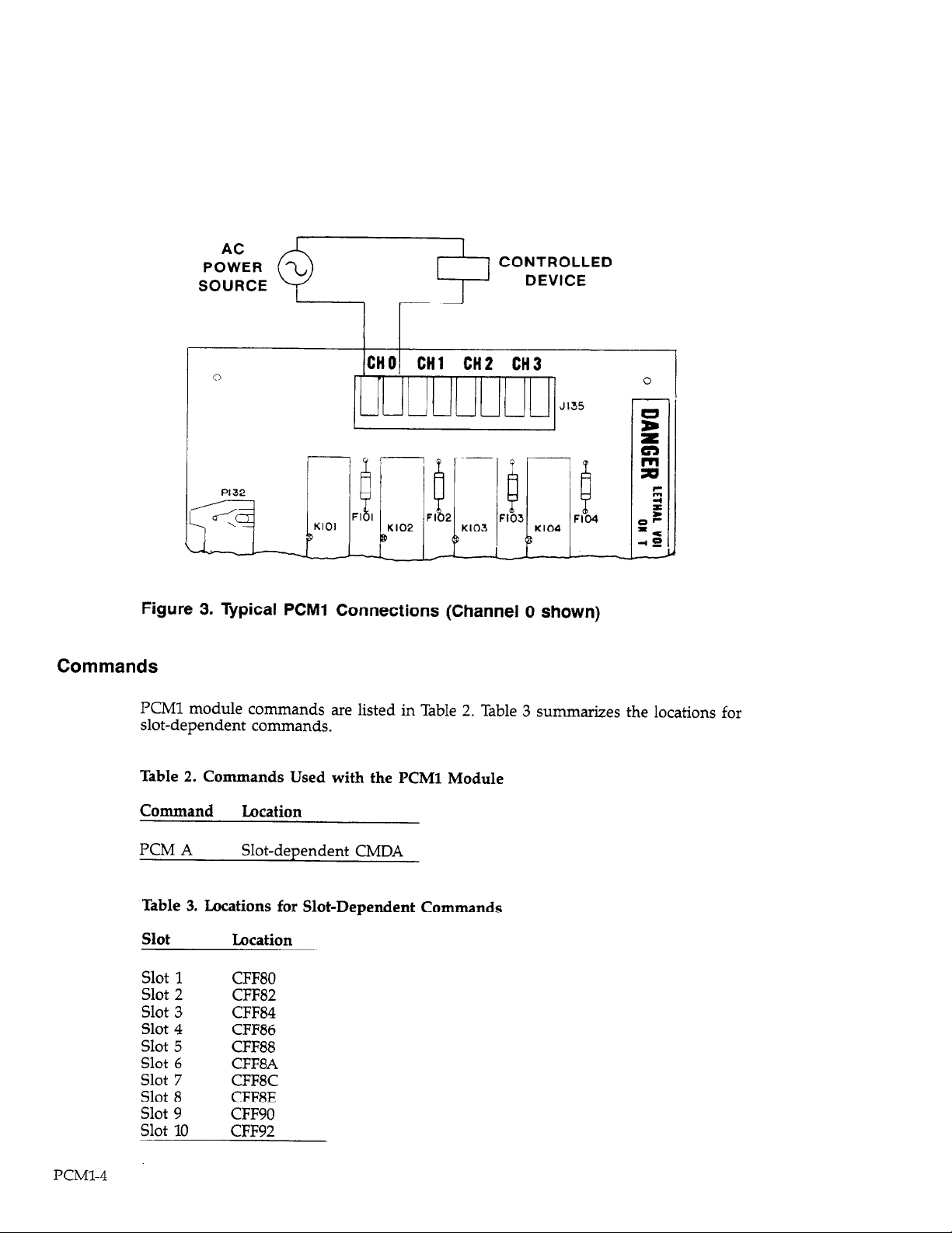
Figure 3. Typical PCMl Connections (Channel 0 shown)
Commands
PCMl module commands are listed in Table 2. Table 3 summarizes the locations for
slot-dependent commands.
Table 2. Commands Used with the PCMl Module
Jl35
PCMl-4
Command
KM A
Table 3. Locations for Slot-Dependent Commands
Slot Location
Slot 1
Slot 2
Slot 3
Slot 4
Slot 5
Slot 6
Slot 7
Slot 8
Slot 9
Slot 10
Location
Slot-dependent CMDA
CFFSO
CFF82
CFF84
CFF86
CFF88
CFFSA
CFFSC
CFWE
CFF90
CFF92
Page 5

PCM A
Location: Slot-dependent CMDA
The four channels of the PCMl module are set simultaneously by writing to a single
command location: KM A. The command word written to this location is made up of
8 bits. Each of the lower 4 (least significant) bits sets the status of one channel, and the
upper four bits are unused. Therefore, the value written to this location should be a
number equivalent to an S-bit binary value, with the lower 4 bits indicating the status
of the four channels (see Table 4).
When switching a single channel on or off, the status of all channels must be known.
Each time the status of the channel is changed, the number written to the KM A location should be retained as a variable in software.
From assembly language, this number can be modified by a logical AND or logical OR
statement with a suitable mask for turning a particular channel on or off. An OR statement is used to turn channels on. The mask should contain l’s in the bit positions of
the channels to be turned on, and O’s in all other positions. Similarly, an AND statement turns channels off. The AND mask should contain O’s in the bit positions of the
channels to be turned on, and l’s in all other positions.
From BASIC, a channel can be turned on or off by adding to, or subtracting from the
stored value the decimal value that represents the bit position for that channel. For example, to turn channel 3 on, it would be necessary to add 8 to the stored variable.
Note that the PCM A location should always be written to, never read.
Table 4. Bit Configuration of Values Written to PCMl
Ix
D6 D5 D4 D3 D2 Dl DO
x x x x Ch3 Ch2 Chl ChO
X X X X 8 4 2 1
X = not used
ChO-Ch3 = Channels 0 through 3
8, 4, etc. = Decimal bit values
Theory of Operation
PCM circuitry is located on two cards: an interface card, and a remote card. A diagram
for both of these boards is located on schematic drawing number 500-256.
Interface Card
UlOl is a quad bistable data latch (74LS375), which stores information from data lines
DO-D3. This latch is refreshed by the negative transition of signal line CMDA, which is
buffered and inverted by segments of hex inverter U102C (74LSO4).
PCMl-5
Page 6

After being inverted and buffered by other segments of U102, the signal drives the
remote solid-state relays (KlOl-K104) through connector Jl31.
Remote Card
Signals for channels O-3 arrive at the remote unit at P132 and are routed to relays
KlOl-K104, respectively (Opto 22 OAC5). Each of these solid-state relays contains an internal light-emitting diode in series with a current limiting resistor, optically driving a
phototransistor, a zero voltage circuit, and high-voltage, high-current, switching
semiconductors that comprise the AC switching element. After passing through the
relay, the signals for channels O-3 pass through status LEDs, DSlOl-DS104. When a
channel is on, current flows through the relay and status diodes, energizing the relay
and turning on the status LED.
The output lines of KlOl-K104 are protected by 5A, l25V fuses FlOl-FlO4, respectively.
PCMl Specifications
Output Channels: 4
Output characteristics:
Configuration: AC Output
Operating voltage: 24-280V AC
Frequency: 25-65Hz
Current: max 3A at 25’C, derate to lA at 7O”C, min 20mA peak 5OA, for 1 cycle surge
Voltage drop: 1.6V max (device on)
Leakage: 5mA max (device off)
Power factor: up to 0.5
Switch form: 1 pole, normally open
Switching technique: optically isolated solid state switch
Switching time: l/2 cycle max (1Oms at 5OH.z)
Operating temperature: -30 to +7O”C
Isolation:
1ooOV RMS input to output
350V RMS channel to channel
Status indication: LED for each channel”on”
Connections: screw terminals for 6-24 AWG wire 8’ ribbon cable to mainframe card
(TTL signals)
Dimensions: 35”(89mm)L x 5.O”(l27mm)W x lX’(46mm)H
PCMl-6
Note: Specifications for remote assembly when used with supplied mainframe card.
Page 7

0
500-252
Cl01 +
C-237-.1 c-314-10
0
-CT-
UlOl
c-15
1
CRIOI
RF-20
0
0
Cl02
u102
c-107
FYI
e-76-IOi.C
Cl08
+
c-313-10
/
PIN I
Page 8

Page 9

I
PCMl CARD
I
ElBA &
_pCl00
100pF
J131
lxlm
J131
ne. I
J131
div 8
I +5v 9 .
+5v 10
r I E 7
t- PCHl EXT. MODULE ‘-1
8
NOTES
1. ALL CRPACITOR VALUES ARE IN MICROFRRROS UNLESS HRRKEO
OTHERVISE. IpF-PICOFARROSI
2- *
3- 47
4. K101-K104 ARE SOLID STATE RELAYS.
DENOTES OIGITAL GROUND.
OENOTES CWSSIS GROUNO.
KEITHLEY INSTRUMENTS INC.
--IAD
TITLE
al?wElmm. mu0 441”
PCMl CARD & PCMl EXT. MODULE
-SIZE Dffl
B
I
R
B
c
0
jOATE FEB 14. 1985 1 SHEET 1 OF 1
E
NUMBER
TL 500-256 :‘.-.
F
APP
PCMl SCHEMATIC DIAGRAM
PCMl-9/PCMl-10
 Loading...