

Page 1

KUSB-3116
Getting Started Manual
KUSB3116-903-01 Rev. A / January 2005
www.keithley.com
A GR
EATER MEASURE OF CONFIDENCE
Page 2

WARRANTY
Keithley Instruments, Inc. warrants this product to be free from defects in material and workmanship for a period of 3 years from
date of shipment.
Keithley Instruments, Inc. warrants the following items for 90 days from the date of shipment: probes, cables, rechargeable batteries,
diskettes, and documentation.
During the warranty period, we will, at our option, either repair or replace any product that proves to be defective.
To exercise this warranty, write or call your local Keithley representative, or contact Keithley headquarters in Cleveland, Ohio.
You will be given prompt assistance and return instructions. Send the product, transportation prepaid, to the indicated service facility. Repairs will be made and the product returned, transportation prepaid. Repaired or replaced products are warranted for the balance of the original warranty period, or at least 90 days.
LIMITATION OF WARRANTY
This warranty does not apply to defects resulting from product modification without Keithley’s express written consent, or misuse
of any product or part. This warranty also does not apply to fuses, software, non-rechargeable batteries, damage from battery leakage, or problems arising from normal wear or failure to follow instructions.
THIS WARRANTY IS IN LIEU OF ALL OTHER WARRANTIES, EXPRESSED OR IMPLIED, INCLUDING ANY IMPLIED
WARRANTY OF MERCHANTABILITY OR FITNESS FOR A PARTICULAR USE. THE REMEDIES PROVIDED HEREIN
ARE BUYER’S SOLE AND EXCLUSIVE REMEDIES.
NEITHER KEITHLEY INSTRUMENTS, INC. NOR ANY OF ITS EMPLOYEES SHALL BE LIABLE FOR ANY DIRECT,
INDIRECT, SPECIAL, INCIDENTAL OR CONSEQUENTIAL DAMAGES ARISING OUT OF THE USE OF ITS INSTRUMENTS AND SOFTWARE EVEN IF KEITHLEY INSTRUMENTS, INC., HAS BEEN ADVISED IN ADVANCE OF THE
POSSIBILITY OF SUCH DAMAGES. SUCH EXCLUDED DAMAGES SHALL INCLUDE, BUT ARE NOT LIMITED TO:
COSTS OF REMOVAL AND INSTALLATION, LOSSES SUSTAINED AS THE RESULT OF INJURY TO ANY PERSON,
OR DAMAGE TO PROPERTY.
A G R E A T E R M E A S U R E O F C O N F I D E N C E
Keithley Instruments, Inc.
Corporate Headquarters • 28775 Aurora Road • Cleveland, Ohio 44139
440-248-0400 • Fax: 440-248-6168 • 1-888-KEITHLEY (534-8453) • www.keithley.com
12/04
Page 3

KUSB-3116
Getting Started Manual
©2005, Keithley Instruments, Inc.
All rights reserved.
First Printing, January 2005
Cleveland, Ohio, U.S.A.
Document Number: KUSB3116-903-01A Rev. A
Page 4

Manual Print History
The print history shown below lists the printing dates of all Revisions and Addenda created for this manual. The Revision Level letter increases alphabetically as the manual undergoes subsequent updates. Addenda, which are released
between Revisions, contain important change information that the user should incorporate immediately into the manual.
Addenda are numbered sequentially. When a new Revision is created, all Addenda associated with the previous Revision
of the manual are incorporated into the new Revision of the manual. Each new Revision includes a revised copy of this
print history page.
Revision A (Document Number KUSB3116-903-01A) ...................................................................... January 2005
All Keithley product names are trademarks or registered trademarks of Keithley Instruments, Inc.
Other brand and product names are trademarks or registered trademarks of their respective holders.
Page 5

Safety Precautions
The following safety precautions should be observed before using
this product and any associated instrumentation. Although some instruments and accessories would normally be used with non-hazardous voltages, there are situations where hazardous conditions
may be present.
This product is intended for use by qualified personnel who recognize shock hazards and are familiar with the safety precautions required to avoid possible injury. Read and follow all installation,
operation, and maintenance information carefully before using the
product. Refer to the manual for complete product specifications.
If the product is used in a manner not specified, the protection provided by the product may be impaired.
The types of product users are:
Responsible body is the individual or group responsible for the use
and maintenance of equipment, for ensuring that the equipment is
operated within its specifications and operating limits, and for ensuring that operators are adequately trained.
Operators use the product for its intended function. They must be
trained in electrical safety procedures and proper use of the instrument. They must be protected from electric shock and contact with
hazardous live circuits.
Maintenance personnel perform routine procedures on the product to keep it operating properly, for example, setting the line voltage or replacing consumable materials. Maintenance procedures
are described in the manual. The procedures explicitly state if the
operator may perform them. Otherwise, they should be performed
only by service personnel.
Service personnel are trained to work on live circuits, and perform
safe installations and repairs of products. Only properly trained service personnel may perform installation and service procedures.
Keithley products are designed for use with electrical signals that
are rated Measurement Category I and Measurement Category II, as
described in the International Electrotechnical Commission (IEC)
Standard IEC 60664. Most measurement, control, and data I/O signals are Measurement Category I and must not be directly connected to mains voltage or to voltage sources with high transient overvoltages. Measurement Category II connections require protection
for high transient over-voltages often associated with local AC
mains connections. Assume all measurement, control, and data I/O
connections are for connection to Category I sources unless otherwise marked or described in the Manual.
Exercise extreme caution when a shock hazard is present. Lethal
voltage may be present on cable connector jacks or test fixtures.
The American National Standards Institute (ANSI) states that a
shock hazard exists when voltage levels greater than 30V RMS,
42.4V peak, or 60VDC are present. A good safety practice is to ex-
pect that hazardous voltage is present in any unknown circuit
before measuring.
Operators of this product must be protected from electric shock at
all times. The responsible body must ensure that operators are prevented access and/or insulated from every connection point. In
some cases, connections must be exposed to potential human contact. Product operators in these circumstances must be trained to
protect themselves from the risk of electric shock. If the circuit is
capable of operating at or above 1000 volts, no conductive part of
the circuit may be exposed.
Do not connect switching cards directly to unlimited power circuits.
They are intended to be used with impedance limited sources.
NEVER connect switching cards directly to AC mains. When connecting sources to switching cards, install protective devices to limit
fault current and voltage to the card.
Before operating an instrument, make sure the line cord is connected to a properly grounded power receptacle. Inspect the connecting
cables, test leads, and jumpers for possible wear, cracks, or breaks
before each use.
When installing equipment where access to the main power cord is
restricted, such as rack mounting, a separate main input power disconnect device must be provided, in close proximity to the equipment and within easy reach of the operator.
For maximum safety, do not touch the product, test cables, or any
other instruments while power is applied to the circuit under test.
ALWAYS remove power from the entire test system and discharge
any capacitors before: connecting or disconnecting cables or jumpers, installing or removing switching cards, or making internal
changes, such as installing or removing jumpers.
Do not touch any object that could provide a current path to the common side of the circuit under test or power line (earth) ground. Always
make measurements with dry hands while standing on a dry, insulated
surface capable of withstanding the voltage being measured.
The instrument and accessories must be used in accordance with its
specifications and operating instructions or the safety of the equipment may be impaired.
Do not exceed the maximum signal levels of the instruments and accessories, as defined in the specifications and operating information, and as shown on the instrument or test fixture panels, or
switching card.
When fuses are used in a product, replace with same type and rating
for continued protection against fire hazard.
Chassis connections must only be used as shield connections for
measuring circuits, NOT as safety earth ground connections.
If you are using a test fixture, keep the lid closed while power is applied to the device under test. Safe operation requires the use of a
lid interlock.
5/03
Page 6

If a screw is present, connect it to safety earth ground using the
wire recommended in the user documentation.
!
The symbol on an instrument indicates that the user should refer to the operating instructions located in the manual.
The symbol on an instrument shows that it can source or measure 1000 volts or more, including the combined effect of normal
and common mode voltages. Use standard safety precautions to
avoid personal contact with these voltages.
The symbol indicates a connection terminal to the equipment
frame.
The WARNING heading in a manual explains dangers that might
result in personal injury or death. Always read the associated information very carefully before performing the indicated procedure.
The CAUTION heading in a manual explains hazards that could
damage the instrument. Such damage may invalidate the warranty.
Instrumentation and accessories shall not be connected to humans.
Before performing any maintenance, disconnect the line cord and
all test cables.
To maintain protection from electric shock and fire, replacement
components in mains circuits, including the power transformer, test
leads, and input jacks, must be purchased from Keithley Instruments. Standard fuses, with applicable national safety approvals,
may be used if the rating and type are the same. Other components
that are not safety related may be purchased from other suppliers as
long as they are equivalent to the original component. (Note that selected parts should be purchased only through Keithley Instruments
to maintain accuracy and functionality of the product.) If you are
unsure about the applicability of a replacement component, call a
Keithley Instruments office for information.
To clean an instrument, use a damp cloth or mild, water based
cleaner. Clean the exterior of the instrument only. Do not apply
cleaner directly to the instrument or allow liquids to enter or spill on
the instrument. Products that consist of a circuit board with no case
or chassis (e.g., data acquisition board for installation into a computer) should never require cleaning if handled according to instructions. If the board becomes contaminated and operation is affected,
the board should be returned to the factory for proper cleaning/servicing.
Page 7

Table of Contents
About this Manual . . . . . . . . . . . . . . . . . . . . . . . . . . . . . . . . . . xi
Intended Audience. . . . . . . . . . . . . . . . . . . . . . . . . . . . . . . . . . . . . . xi
How this Manual is Organized . . . . . . . . . . . . . . . . . . . . . . . . . . . xi
Conventions Used in this Manual . . . . . . . . . . . . . . . . . . . . . . . . . xii
Related Information . . . . . . . . . . . . . . . . . . . . . . . . . . . . . . . . . . . . . xii
Where To Get Help. . . . . . . . . . . . . . . . . . . . . . . . . . . . . . . . . . . . . xiii
Chapter 1: Overview . . . . . . . . . . . . . . . . . . . . . . . . . . . . . . . . 1
Hardware Features. . . . . . . . . . . . . . . . . . . . . . . . . . . . . . . . . . . . . . . 2
Supported Software . . . . . . . . . . . . . . . . . . . . . . . . . . . . . . . . . . . . . . 4
Getting Started Procedure. . . . . . . . . . . . . . . . . . . . . . . . . . . . . . . . . 5
Chapter 2: Preparing to Use a Module. . . . . . . . . . . . . . . . . . 7
Unpacking . . . . . . . . . . . . . . . . . . . . . . . . . . . . . . . . . . . . . . . . . . . . . . 9
Checking the System Requirements . . . . . . . . . . . . . . . . . . . . . . . 10
Installing the Software. . . . . . . . . . . . . . . . . . . . . . . . . . . . . . . . . . . 11
Chapter 3: Setting Up and Installing a Module . . . . . . . . . . 13
Applying Power to the Module . . . . . . . . . . . . . . . . . . . . . . . . . . . 15
Configuring the Device Driver. . . . . . . . . . . . . . . . . . . . . . . . . . . . 16
Attaching Modules to the Computer. . . . . . . . . . . . . . . . . . . . . . . 18
Connecting One or Two Modules. . . . . . . . . . . . . . . . . . . . . . 18
Connecting Multiple Modules Using an Expansion Hub . . 20
Chapter 4: Wiring Signals . . . . . . . . . . . . . . . . . . . . . . . . . . . 23
Preparing to Wire Signals . . . . . . . . . . . . . . . . . . . . . . . . . . . . . . . . 25
Wiring Recommendations . . . . . . . . . . . . . . . . . . . . . . . . . . . . 25
vii
Page 8

Contents
Wiring Methods. . . . . . . . . . . . . . . . . . . . . . . . . . . . . . . . . . . . . 26
Wiring Signals to the BNC Connectors . . . . . . . . . . . . . 28
Wiring Signals to the D-Sub Connectors on the BNC
Connection Box . . . . . . . . . . . . . . . . . . . . . . . . . . . . . . . . 28
Analog Input Connector . . . . . . . . . . . . . . . . . . . . . . 28
Digital In/Out Connector . . . . . . . . . . . . . . . . . . . . . 30
C/T, DAC, Clk, Trig Connector . . . . . . . . . . . . . . . . 31
Connecting Analog Input Signals . . . . . . . . . . . . . . . . . . . . . . . . . 33
Connecting Single-Ended Voltage Inputs . . . . . . . . . . . . . . . 34
Connecting Pseudo-Differential Voltage Inputs . . . . . . . . . . 35
Connecting Differential Voltage Inputs . . . . . . . . . . . . . . . . . 37
Connecting Current Loop Inputs . . . . . . . . . . . . . . . . . . . . . . 40
Connecting Analog Output Signals. . . . . . . . . . . . . . . . . . . . . . . . 41
Connecting Digital I/O Signals . . . . . . . . . . . . . . . . . . . . . . . . . . . 42
Connecting Counter/Timer Signals . . . . . . . . . . . . . . . . . . . . . . . 43
Connecting Signals for Event Counting Operations . . . . . . 43
Connecting Signals for Up/Down Counting Operations . . 45
Connecting Signals for Frequency Measurement
Operations . . . . . . . . . . . . . . . . . . . . . . . . . . . . . . . . . . . . . . . . 46
Connecting Signals for Period/Pulse Width Measurement
Operations . . . . . . . . . . . . . . . . . . . . . . . . . . . . . . . . . . . . . . . . 47
Connecting Signals for Edge-to-Edge Measurement
Operations . . . . . . . . . . . . . . . . . . . . . . . . . . . . . . . . . . . . . . . . 48
Connecting Signals for Pulse Output Operations . . . . . . . . 49
viii
Chapter 5: Verifying the Operation of a Module . . . . . . . . . 51
Overview . . . . . . . . . . . . . . . . . . . . . . . . . . . . . . . . . . . . . . . . . . . . . . 53
Running the Quick Data Acq Application . . . . . . . . . . . . . . . . . . 54
Performing a Single-Value Analog Input Operation . . . . . . 54
Performing a Single-Value Analog Output Operation . . . . 55
Performing a Continuous Analog Input Operation. . . . . . . 56
Page 9

Performing a Single-Value Digital Input Operation . . . . . . 57
Performing a Single-Value Digital Output Operation. . . . . 58
Performing a Frequency Measurement Operation. . . . . . . . 59
Performing a Pulse Output Operation. . . . . . . . . . . . . . . . . . 60
Appendix A: Ground, Power, and Isolation Connections . 61
Index . . . . . . . . . . . . . . . . . . . . . . . . . . . . . . . . . . . . . . . . . . . . . 65
Contents
ix
Page 10

Contents
x
Page 11

About this Manual
This manual describes how to install and set up your KUSB-3116
module and device driver, and verify that your module is working
properly.
Intended Audience
This document is intended for engineers, scientists, technicians, or
others responsible for installing and setting up a KUSB-3116 module
to perform data acquisition operations. It is assumed that you are
familiar with the requirements of your application. It is also assumed
that you are familiar with the Microsoft
Windows XP operating system.
How this Manual is Organized
This manual is organized as follows:
• Chapter 1, “Overview,” describes the key features of the
KUSB-3116 hardware and software, and provides an overview of
the getting started procedure.
®
Windows® 2000 or
• Chapter 2, “Preparing to Use a Module,” describes how to
unpack the KUSB-3116 package, check the system requirements,
and install the software under Windows 2000 or Windows XP.
• Chapter 3, “Setting Up and Installing a Module,” describes how
to install a KUSB-3116 module, how to apply power to the
module, and how to configure the device driver.
• Chapter 4, “Wiring Signals,” describes how to wire signals to a
KUSB-3116 module.
• Chapter 5, “Verifying the Operation of a Module,” describes how
to verify the operation of the KUSB-3116 module with the Quick
Data Acq application.
xi
Page 12

About this Manual
Conventions Used in this Manual
• Appendix A, “Ground, Power, and Isolation Connections,”
describes the internal ground, power, and isolation connections
on the KUSB-3116 module.
An index completes this manual.
The following conventions are used in this manual:
• Notes provide useful information that requires special emphasis,
cautions provide information to help you avoid losing data or
damaging your equipment, and warnings provide information to
help you avoid catastrophic damage to yourself or your
equipment.
• Items that you select or type are shown in bold.
• Courier font is used to represent source code.
xii
Related Information
Refer to the following documents for more information on using the
KUSB-3116 module:
• KUSB-3116 User’s Manual, included on the CD provided with the
KUSB-3116 module. This manual describes the features of the
KUSB-3116 module and the device driver in detail.
• DataAcq SDK User’s Manual. For programmers who are
developing their own application programs using the Microsoft
C compiler, this manual describes how to use the DT-Open
TM
Layers
access the capabilities of your module.
DataAcq SDKTM in Windows 2000 or Windows XP to
Page 13

• DTx-EZ Getting Started Manual. This manual describes how to use
the ActiveX controls provided in DTx-EZ
capabilities of your module in Microsoft Visual Basic® or Visual
C++®.
• DT-LV Link Getting Started Manual. This manual describes how to
use DT-LV Link
language to access the capabilities of your module.
• Microsoft Windows 2000 or Windows XP documentation.
• USB web site (http://www.usb.org).
Where To Get Help
Should you run into problems installing or using your KUSB-3116
module, please call the Keithley Technical Support Department.
About this Manual
TM
to access the
TM
with the LabVIEW® graphical programming
xiii
Page 14

About this Manual
xiv
Page 15

1
Overview
Hardware Features. . . . . . . . . . . . . . . . . . . . . . . . . . . . . . . . . . . . . . . 2
Supported Software . . . . . . . . . . . . . . . . . . . . . . . . . . . . . . . . . . . . . . 4
Getting Started Procedure. . . . . . . . . . . . . . . . . . . . . . . . . . . . . . . . . 5
1
Page 16

Chapter 1
Hardware Features
The KUSB-3116 is a high-performance, multifunction data acquisition
modules for the USB (Ver. 2.0 or Ver. 1.1) bus. The key hardware
features of the module is as follows:
• Installed in a metal BNC box to provide easy connections.
• Simultaneous operation of analog input, analog output, digital
I/O, and counter/timer subsystems.
• Analog input subsystem:
− 16-bit A/D converter.
− Throughput rate up to 500 kSamples/s.
− 16 single-ended or 8 differential analog input channels.
− Programmable gain of 1, 2, 4, or 8 provides input ranges of
±10, ±5, ±2.5, and ±1.25 V.
− 1024-location channel-gain list. You can cycle through the
channel-gain list using continuous scan mode or triggered
scan mode. The maximum sampling rate when using the
channel-gain list is 500 kSamples/s.
• Analog output subsystem:
− Four 16-bit D/A converters.
− Output rate up to 500 kSamples/s.
− Output range of ±10 V.
− The DACs are deglitched to prevent noise from interfering
with the output signal.
− Output channel list. You can cycle through the output channel
list using continuous output mode or waveform mode. For
waveform generation mode, you can simultaneously update
all four DACs at 500 kS/s per channel; for continuous output
mode, you can simultaneously update all four DACs at
250 kS/s per channel.
2
Page 17

• Digital I/O subsystem:
Overview
− One digital input port, consisting of 16 digital input lines. You
can program any of the first eight digital input lines to
perform interrupt-on-change operations. You can read the
value of the digital input port using the analog input
channel-gain list.
− One digital output port, consisting of 16 digital output lines.
You can output the value of the digital output port using the
output channel list.
− An additional dynamic digital output line that changes state
whenever an analog input channel is read.
• Five 32-bit counter/timer (C/T) channels that perform event
counting, up/down counting, frequency measurement,
edge-to-edge measurement, continuous pulse output, one-shot,
and repetitive one-shot operations. You can read the value of one
or more of the C/T channels using the analog input channel-gain
list.
• External or internal clock source.
• Trigger operations using a software command, an analog
threshold value, or an external digital input value as the trigger
event.
1
1
1
1
1
1
• 500 V galvanic isolation barrier that prevents ground loops to
maximize analog signal integrity and protect your computer.
1
1
1
3
Page 18

Chapter 1
Supported Software
The KUSB-3116 software, which is shipped on the CD provided with
the module, includes the following software components:
• Device Driver − This software must be installed and loaded
before you can use a KUSB-3116 module with any of the
supported software packages or utilities.
• Quick Data Acq application − This application provides a quick
way to get a KUSB-3116 module up and running. Using the
Quick Data Acq application, you can verify the features of the
module, display data on the screen, and save data to disk.
• DataAcq SDK − This DT-Open Layers Software Develop Kit
(SDK) allows programmers to develop application programs for
the KUSB-3116 using the Microsoft C compiler in Windows 2000
or Windows XP.
• DTx-EZ − This software package contains ActiveX controls that
allow Microsoft Visual Basic® or Visual C++® programmers to
access the capabilities of the KUSB-3116 module.
• DT-LV Link − This software package allows LabVIEW®
programmers to access the capabilities of the KUSB-3116 module.
4
Page 19

Getting Started Procedure
The flow diagram shown in Figure 1 illustrates the steps needed to
get started using the KUSB-3116 module. This diagram is repeated in
each chapter; the shaded area in the diagram shows you where you
are in the getting started procedure.
Prepare to Use the Module
(see Chapter 2 starting on page 7)
Set Up and Install the Module
(see Chapter 3 starting on page 13)
Overview
1
1
1
Wire Signals to the BNC Connection Box
(see Chapter 4 starting on page 23)
Verify the Operation of the Module
(see Chapter 5 starting on page 51)
Figure 1: Getting Started Flow Diagram
1
1
1
1
1
1
5
Page 20

Chapter 1
6
Page 21

2
Preparing to Use a Module
Unpacking . . . . . . . . . . . . . . . . . . . . . . . . . . . . . . . . . . . . . . . . . . . . . . 9
Checking the System Requirements . . . . . . . . . . . . . . . . . . . . . . . 10
Installing the Software. . . . . . . . . . . . . . . . . . . . . . . . . . . . . . . . . . . 11
7
Page 22

Chapter 2
Prepare to Use the Module
(this chapter)
Set Up and Install the Module
(see Chapter 3 starting on page 13)
Wire Signals
(see Chapter 4 starting on page 23)
Verify the Operation of the Module
(see Chapter 5 starting on page 51)
8
Page 23

Unpacking
Open the shipping box and verify that the following items are
present:
• KUSB-3116 BNC module,
•USB cable,
• Power supply,
Preparing to Use a Module
2
2
• Keithley CD.
If an item is missing or damaged, contact Keithley Technical Support.
Once you have unpacked your module, check the system
requirements, as described in the next section.
2
2
2
2
2
2
2
9
Page 24

Chapter 2
Checking the System Requirements
For reliable operation, your KUSB-3116 module requires the
following:
• PC with Pentium 233 MHz (or higher) processor.
• Windows 2000 or Windows XP (Professional Edition) operating
system.
For USB Ver. 2.0 support, make sure that you install Service Pack
1 (for Windows XP) or Service Pack 4 (for Windows 2000). In
addition, for some systems, you may have to disable standby
mode. If you are not sure whether you are using USB Ver. 1.1 or
Ver. 2.0, run the Open Layers Control Panel applet, described on
page 16.
• One or more USB ports (Ver. 2.0 or Ver. 1.1). USB Ver. 2.0 is
recommended for optimal performance.
• 64 MB (or more) of RAM; 128 MB (or more) recommended.
• One or more CD-ROM drives.
10
• Super VGA (800 x 600 or higher resolution) display monitor.
Once you have verified that your system meets the system
requirements, install the software, as described in the next section.
Page 25

Installing the Software
To install the driver software, Data Acq SDK, DTx-EZ, and the Quick
Data Acq software, perform the following steps:
Preparing to Use a Module
2
1. Insert the Keithley CD into your CD-ROM drive.
2. Click Start from the Task Bar, then click Run.
The Run dialog box appears.
3. In the Command Line edit box, enter D:\Setup.Exe.
If your CD-ROM is not in drive D:, enter the letter of the drive where
your CD-ROM is located. The welcome screen appears.
4. Click Install Drivers and SDK.
5. Click Install now!
The installation wizard appears.
6. Click Next.
You are prompted for the destination location.
7. Either change the directory path and/or name using Browse or
accept the default directory, then click Next.
8. Click Next to copy the files.
9. Click Finish.
10. Click Quit Installer.
2
2
2
2
2
2
2
2
11
Page 26

Chapter 2
12
Page 27

3
Setting Up and
Installing a Module
Applying Power to the Module . . . . . . . . . . . . . . . . . . . . . . . . . . . 15
Configuring the Device Driver. . . . . . . . . . . . . . . . . . . . . . . . . . . . 16
Attaching Modules to the Computer. . . . . . . . . . . . . . . . . . . . . . . 18
13
Page 28

Chapter 3
Prepare to Use the Module
(see Chapter 2 starting on page 7)
Set Up and Install the Module
(this chapter)
Wire Signals to the BNC Connection Box
(see Chapter 4 starting on page 23)
Verify the Operation of the Module
(see Chapter 5 starting on page 51)
Note: The KUSB-3116 module is factory-calibrated and requires no
further adjustment prior to installation.
14
Page 29

Applying Power to the Module
The KUSB-3116 module is shipped with a +5V power supply and
cable. To apply power to the KUSB-3116 module, perform the
following steps:
Setting Up and Installing a Module
3
+5 V Power
Supply
To wall outlet
1. Connect the +5 V power supply to the power connector on the
KUSB-3116 module. Refer to Figure 2.
Power Connector
LED
USB Port
Figure 2: Attaching a +5 V Power Supply to the Module
2. Plug the power supply to a wall outlet.
Continue by configuring the device driver, as described in the next
section.
KUSB-3116
Module
3
3
3
3
3
3
3
3
15
Page 30

Chapter 3
Configuring the Device Driver
To configure the device driver for the KUSB-3116 module, perform
the following steps:
1. If you have not already done so, power up the host computer and
all peripherals.
2. From the Windows Start menu, select Settings|Control Panel.
3. From the Control Panel, double-click Open Layers Control
Panel.
The Data Acquisition Control Panel dialog box appears.
4. Click the KUSB-3116 module that you want to configure, then
click Advanced.
The Control Panel dialog box appears.
5. If you are using differential analog input channels, it is
recommended that you select the 10k Ohm Resistor
Terminations checkbox for each analog input channel on the
module. This ensures that 10 kΩ of bias return termination
resistance is used for the analog input channels. (This is the
default configuration.) Bias return termination resistance is
particularly useful when your differential source is floating.
16
If you are using single-ended analog input channels, clear the
checkbox for each analog input channel so that bias return
resistance is not used.
6. If required, select the digital input line(s) that you want to use for
interrupt-on-change operations. When any of the selected lines
changes state, the module reads the entire 16-bit digital input
value and generates an interrupt.
7. Click OK.
8. If you want to rename the module, click Edit Name, enter a new
name for the module, then click OK. The name is used to identify
the module in all subsequent applications.
9. When you are finished configuring the module, click Close.
Page 31

Setting Up and Installing a Module
10. Repeat steps 4 to 8 for the other modules that you want to
configure.
11. Close the Data Acquisition Control Panel dialog box.
Continue by connecting the KUSB-3116 module to the computer, as
described in the next section.
3
3
3
3
3
3
3
3
3
17
Page 32

Chapter 3
Attaching Modules to the Computer
This section describes how to attach KUSB-3116 modules to the host
computer.
Notes: Most computers have two USB ports that allow direct
connection to USB devices. If your application requires more than
two KUSB-3116 modules, you can expand the number of USB
devices attached to a single USB port by using expansion hubs. For
more information, refer to page 20.
You can unplug a module, then plug it in again, if you wish, without
causing damage. This process is called hot-swapping. Your
application may take a few seconds to recognize a module once it is
plugged back in.
Connecting One or Two Modules
18
To connect one or two KUSB-3116 modules to a USB port of the
computer, perform the following steps:
1. Make sure that you have attached a power supply to the module.
2. Attach one end of the USB cable to the USB port on the module.
3. Attach the other end of the USB cable to one of the USB ports on
the host computer, as shown in Figure 3.
The operating system automatically detects the USB module. If the
power supply and module are attached correctly, the LED turns green.
Page 33

Setting Up and Installing a Module
Host Computer
Figure 3: Attaching the Module to the Host Computer
4. If you previously installed the device driver, ignore the
remaining steps, and repeat steps 1 and 2 to attach another
KUSB-3116 module to the host computer, if desired.
If you have not yet installed the device driver, the New
Hardware Found wizard appears. Click Next to have the wizard
search for the device driver, then proceed to step 5.
5. Click the option to search for the driver, then click Next.
USB Ports
USB Cable
Powe r Ca ble
KUSB-3116
Module
3
3
3
3
3
3
6. Click the option to specify the location, browse to the location on
the CD that contains the driver files, then click Next.
7. Click Next.
8. Click Finish.
A New Hardware Found dialog box appears indicating that Windows is
installing the driver for the USB module.
9. Repeat the steps 1 to 3 to attach another KUSB-3116 module to
the host computer, if desired.
3
3
3
19
Page 34

Chapter 3
Connecting Multiple Modules Using an Expansion Hub
Expansion hubs are powered by their own external power supply.
Theoretically, you can connect up to five expansion hubs to a USB
port on the host computer. However, the practical number of
KUSB-3116 modules that you can connect to a single USB port
depends on the throughput you want to achieve. Each of the hubs
supports up to four KUSB-3116 modules.
Note: The bandwidth of the USB Ver. 1.1 bus is 12 Mbits/second;
the bandwidth of the USB Ver. 2.0 bus is 480 Mbits/second.
Particularly if you are using the USB Ver. 2.0 bus, you may be
limited in the number of KUSB-3116 modules that you can connect
to a single USB port.
To connect multiple KUSB-3116 modules to an expansion hub,
perform the following steps:
20
1. Make sure that you have attached a power supply to the module.
2. Attach one end of the USB cable to the KUSB-3116 module and
the other end of the USB cable to an expansion hub.
3. Connect the power supply for the expansion hub to an external
power supply.
4. Connect the expansion hub to the USB port on the host computer
using another USB cable.
The operating system automatically detects the USB device. If the power
supply and module are attached correctly, the LED turns green.
5. If you have previously installed the device driver, ignore the
remaining steps, and repeat steps 1 to 3 until you have attached
the number of expansion hubs (up to five) and modules (up to
four per hub) that you require. Refer to Figure 4.
Page 35

Setting Up and Installing a Module
If you have not installed the device driver, the New Hardware
Found wizard appears. Click Next to have the wizard search for
the device driver. Proceed to step 6.
3
KUSB-3116
Module
Host Computer
USB Cable
Power Supply
for Hub
KUSB-3116
Module
USB Cables
Figure 4: Attaching Multiple KUSB-3116 Modules Using Expansion Hubs
Power Su pply
for Module
USB Cables
KUSB-3116
Module
USB Cable
Expansion Hubs
Power Supply
for Hub
KUSB-3116
Module
3
3
3
3
3
3
6. Click the option to search for the driver, then click Next.
7. Click the option to specify the location, browse to the location on
the CD that contains the driver files, then click Next.
8. Click Next.
9. Click Finish.
A New Hardware Found dialog box appears indicating that Windows is
installing the driver for the USB device.
3
3
21
Page 36

Chapter 3
10. Repeat steps 1 to 3 until you have attached the number of
expansion hubs (up to five) and modules (up to four per hub)
that you require.
The operating system automatically detects the USB devices as they are
installed.
Continue with the instructions on wiring in Chapter 4 starting on
page 23.
22
Page 37

4
Wiring Signals
Preparing to Wire Signals . . . . . . . . . . . . . . . . . . . . . . . . . . . . . . . . 25
Connecting Analog Input Signals . . . . . . . . . . . . . . . . . . . . . . . . . 33
Connecting Analog Output Signals. . . . . . . . . . . . . . . . . . . . . . . . 41
Connecting Digital I/O Signals . . . . . . . . . . . . . . . . . . . . . . . . . . . 42
Connecting Counter/Timer Signals . . . . . . . . . . . . . . . . . . . . . . . 43
23
Page 38

Chapter 4
Prepare to Use a Module
(see Chapter 2 starting on page 7)
Set Up and Install the Module
(see Chapter 3 starting on page 13)
Wire Signals
(this chapter)
Verify the Operation of the Module
(see Chapter 5 starting on page 51)
24
Page 39

Preparing to Wire Signals
CAUTION:
Wiring Signals
4
To avoid electrostatic sensitivity, it is recommended that you unplug
your KUSB-3116 module from the computer before wiring signals.
This section provides recommendations and information about
wiring signals to the KUSB-3116 module.
Wiring Recommendations
Keep the following recommendations in mind when wiring signals to
a BNC connection box:
• Use individually shielded twisted-pair wire (size 14 to 26 AWG)
in highly noisy electrical environments.
• Separate power and signal lines by using physically different
wiring paths or conduits.
• To avoid noise, do not locate the box and cabling next to sources
that produce high electromagnetic fields, such as large electric
motors, power lines, solenoids, and electric arcs, unless the
signals are enclosed in a mumetal shield.
• Prevent electrostatic discharge to the I/O while the box is
operational.
4
4
4
4
4
4
• Connect all unused analog input channels to analog ground.
4
4
25
Page 40

Chapter 4
Wiring Methods
The KUSB-3116 module contains both BNC connectors and 37-pin,
D-sub connectors, as shown in Figure 5.
Analog Input
AD Ch12
AD Ch8
AD Ch4
AD Ch0
AD Ch13 AD Ch14 AD Ch15 DAC Ch0
AD Ch9 AD Ch10 AD Ch11
AD Ch5 AD Ch7
AD Ch1 AD Ch2
AD Ch6
AD Ch3
DAC Ch1
DAC Ch2
DAC Ch3
DAC Cl ock
AD Clock
DAC Trig
AD Trig
Figure 5: KUSB-3116 Module
You can wire signals to the KUSB-3116 module in one of the
following ways:
• Analog input signals – You can wire analog input signals in one
of the following ways:
− Using the BNC connectors labelled AD Ch0 to AD Ch15.
− Using the appropriate pins on the Analog Input connector.
Refer to Appendix A in the KUSB-3116 User’s Manual for
information about the required mating connectors.
Digital I/O
C\T, DAC, Clk, Trig
26
Page 41

Wiring Signals
• Analog output signals – You can wire analog output signals in
one of the following ways:
− Using the BNC connectors labelled DAC Ch0 to DAC Ch3.
− Using the appropriate pins on the C\T, DAC, Clk, Trig
connector. Refer to Appendix A in the KUSB-3116 User’s
Manual for information about the required mating connectors.
• Digital I/O signals – To wire digital I/O signals, you must use
the appropriate pins on the Digital I/O connector. Refer to
Appendix A in the KUSB-3116 User’s Manual for information
about the required mating connectors.
• Counter/timer signals – To wire counter/timer signals, you must
use the appropriate pins on the C\T, DAC, Clk, Trig connector.
Refer to Appendix A in the KUSB-3116 User’s Manual for
information about the required mating connectors.
• External A/D clock or trigger signal – You can wire external
clock/trigger signals in one of the following ways:
− Using the BNC connectors labelled AD Clock and AD Trig.
− Using the appropriate pins on the C\T, DAC, Clk, Trig
connector. Refer to Appendix A in the KUSB-3116 User’s
Manual for information about the required mating connectors.
• External DAC clock or trigger signal – You can wire external
clock/trigger signals in one of the following ways:
4
4
4
4
4
4
− Using the BNC connectors labelled DAC Clock and DAC Trig.
− Using the appropriate pins on the C\T, DAC, Clk, Trig
connector. Refer to Appendix A in the KUSB-3116 User’s
Manual for information about the required mating connectors.
The following sections describe how to wire signals using the BNC
connectors and how to wire signals using the appropriate D-sub
connector.
4
4
4
27
Page 42

Chapter 4
Wiring Signals to the BNC Connectors
To wire signals using the BNC connectors, connect the appropriate
BNC connector to the appropriate input/output using a BNC cable.
The KUSB-3116 module, shown in Figure 5 on page 26, contains 24
BNC connectors (16 BNC connectors for single-ended analog inputs,
four BNC connectors for analog outputs, and four BNC connectors
for external clocks and triggers).
Wiring Signals to the D-Sub Connectors on the BNC Connection Box
If you do not want to use the BNC connectors or if you want to
connect digital I/O or counter/timer signals to the KUSB-3116
module, you can use the 37-pin, D-sub connectors. These connectors
are described in the following sections.
Analog Input Connector
28
The Analog Input connector allows you to access the analog input
signals. Tabl e 1 lists the pin assignments for the analog input
connector.
Table 1: Analog Input Connector Pin Assignments
Pin
Assignment
1 Analog Input 0 2 Analog Input 1
3 Analog Input 2 4 Analog Input 3
5 Analog Input 4 6 Analog Input 5
7 Analog Input 6 8 Analog Input 7
9 Analog Input 8 10 Analog Input 9
Signal Description
Pin
Assignment
Signal Description
Page 43

Table 1: Analog Input Connector Pin Assignments (cont.)
Wiring Signals
Pin
Assignment
11 Analog Input 10 12 Analog Input 11
13 Analog Input 12 14 Analog Input 13
15 Analog Input 14 16 Analog Input 15
17 Amplifier Low 18 +5 V Analog
19 Chassis Ground 20 Analog Input 0 Return/
21 Analog Input 1 Return/
23 Analog Input 3 Return/
25 Analog Input 5 Return/
27 Analog Input 7 Return/
29 Analog Input 9 Return
31 Analog Input 11 Returna32 Analog Input 12 Return
33 Analog Input 13 Returna34 Analog Input 14 Return
35 Analog Input 15 Returna36 Analog Ground
Signal Description
a
Analog In 9
Analog In 11
Analog In 13a
Analog In 15
a
a
a
Pin
Assignment
22 Analog Input 2 Return/
24 Analog Input 4 Return/
26 Analog Input 6 Return/
28 Analog Input 8 Return
30 Analog Input 10 Return
Signal Description
Analog In 8a
a
Analog In 10
Analog In 12
Analog In 14a
a
4
4
4
4
4
a
a
a
a
4
4
37 Digital Ground
a. The first signal description (Return) applies to the differential configuration for all modules.
The second signal description applies to the single-ended configuration for the module.
4
4
29
Page 44

Chapter 4
Digital In/Out Connector
The Digital In/Out connector allows you to access the digital I/O
signals. Tabl e 2 lists the pin assignments for the Digital In/Out
connector.
Table 2: Digital In/Out Connector Pin Assignments
Pin
Assignment
1 Digital Input 0 2 Digital Input 1
3 Digital Input 2 4 Digital Input 3
5 Digital Input 4 6 Digital Input 5
7 Digital Input 6 8 Digital Input 7
9 Digital Input 8 10 Digital Input 9
11 Digital Input 10 12 Digital Input 11
13 Digital Input 12 14 Digital Input 13
15 Digital Input 14 16 Digital Input 15
17 Digital Ground 18 Digital Ground
19 Not Used 20 Digital Output 0
21 Digital Output 1 22 Digital Output 2
23 Digital Output 3 24 Digital Output 4
25 Digital Output 5 26 Digital Output 6
27 Digital Output 7 28 Digital Output 8
Signal Description
Pin
Assignment
Signal Description
30
29 Digital Output 9 30 Digital Output 10
31 Digital Output 11 32 Digital Output 12
Page 45
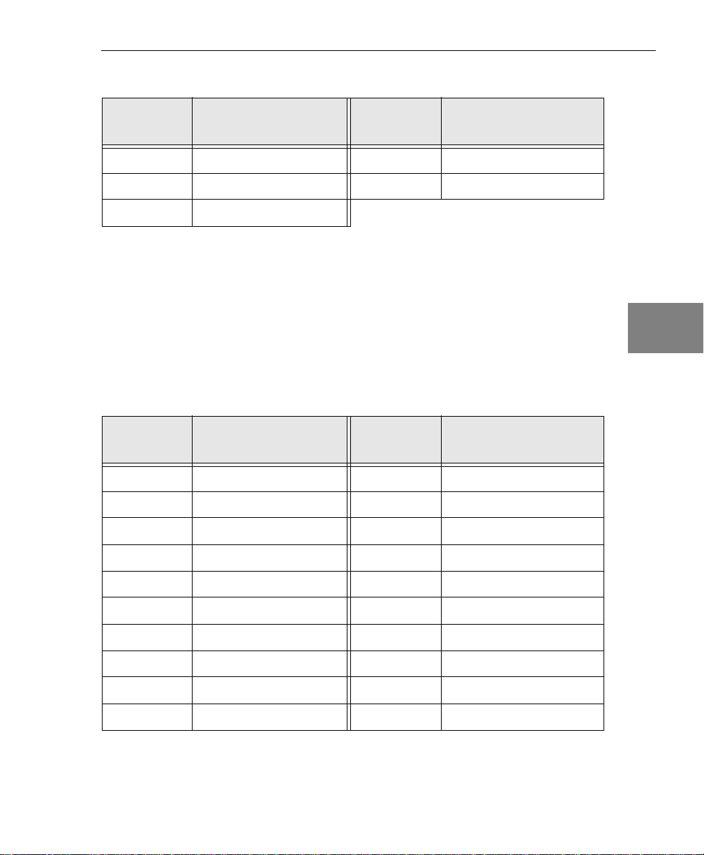
Table 2: Digital In/Out Connector Pin Assignments (cont.)
Wiring Signals
Pin
Assignment
33 Digital Output 13 34 Digital Output 14
35 Digital Output 15 36 Dynamic Digital Output
37 Digital Ground
Pin
Assignment
1 Analog Output 0 2 Analog Output 1
3 Analog Output 2 4 Analog Output 3
Signal Description
C/T, DAC, Clk, Trig Connector
The C/T, DAC, Clk, Trig connector allows you to access the
counter/timer, analog output, external clock, and external trigger
signals. Tabl e 3 lists the pin assignments for the C/T, DAC, Clk, Trig
connector.
Table 3: C/T, DAC, Clk, Trig Connector
Signal Description
Pin
Assignment
Pin
Assignment
Signal Description
Signal Description
4
4
4
4
4
4
5 Digital Ground 6 External DAC Clock
7 External ADC Clock 8 Counter 0 Clock
9 Counter 0 Out 10 Counter 1 Clock
11 Counter 1 Out 12 Counter 2 Clock
13 Counter 2 Out 14 Counter 3 Clock
15 Counter 3 Out 16 Counter 4 Clock
17 Counter 4 Out 18 Digital Ground
19 Not Used 20 Analog Output 0 Return
4
4
4
31
Page 46

Chapter 4
Table 3: C/T, DAC, Clk, Trig Connector (cont.)
Pin
Assignment
21 Analog Output 1 Return 22 Analog Output 2 Return
23 Analog Output 3 Return 24 Digital Ground
25 External DAC Trigger 26 External ADC Trigger
27 Digital Ground 28 Counter 0 Gate
29 Digital Ground 30 Counter 1 Gate
31 Digital Ground 32 Counter 2 Gate
33 Digital Ground 34 Counter 3 Gate
35 Digital Ground 36 Counter 4 Gate
37 Digital Ground
Signal Description
Pin
Assignment
Signal Description
32
Page 47

Connecting Analog Input Signals
The KUSB-3116 module supports both voltage and current loop
inputs. You can connect analog input signals to the module in the
following configurations:
Wiring Signals
4
• Single-ended − Choose this configuration when you want to
measure high-level signals, noise is not significant, the source of
the input is close to the module, and all the input signals are
referred to the same common ground.
• Pseudo-Differential − Choose this configuration when noise or
common-mode voltage (the difference between the ground
potentials of the signal source and the ground of the screw
terminal panel or between the grounds of other signals) exists
and the differential configuration is not suitable for your
application. This option provides less noise rejection than the
differential configuration; however, the number of analog input
channels available is the same as for single-ended configuration.
• Differential − Choose this configuration when you want to
measure low-level signals, noise is a significant part of the signal,
or common-mode voltage exists.
This section describes how to connect single-ended,
pseudo-differential, and differential voltage inputs, as well as current
loops, to the KUSB-3116 module.
4
4
4
4
4
4
4
4
33
Page 48
Chapter 4
Connecting Single-Ended Voltage Inputs
Note: If you are using single-ended inputs, make sure that bias
return resistance is disabled in the Open Layers Control Panel
applet. Refer to page 16 for more information.
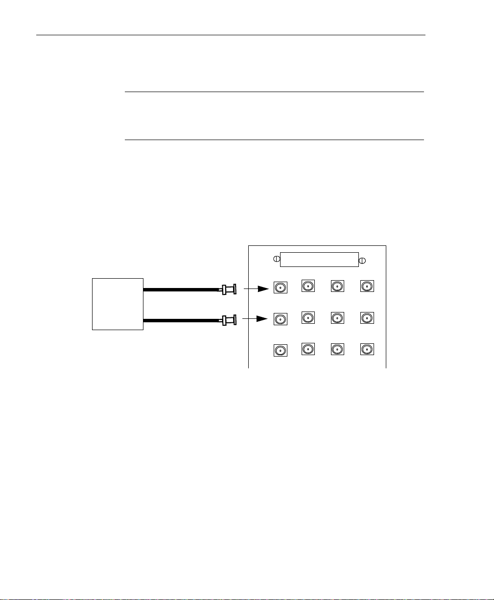
Figure 6 shows how to connect single-ended voltage inputs (channels
0 and 1, in this case) to the BNC connectors on the KUSB-3116
module.
KUSB-3116 Module
Analog Input
Analog In 0
AD0
AD1
AD2
AD4
AD6 AD5
Signal
Source
Note that the BNC connection box
automatically connects the Analog
Ground and Amp Low signals together.
Analog In 1
AD8
AD9AD10
AD 12
AD13AD14
34
Figure 6: Connecting Single-Ended Inputs to the BNC Connectors
Figure 7 shows how to connect single-ended voltage inputs (channels
0 and 1, in this case) using your own cable/screw terminal panel.
Page 49

Wiring Signals
Signal Source
-
source 1
V
-
Vsource 0
Figure 7: Connecting Single-Ended Inputs to a Screw Terminal Panel
+
+
Analog Ground
Screw Terminal Panel
Analog In 0
Analog In 1
1
2
17
Amp Low (internally
connected to Analog Ground)
36
Connecting Pseudo-Differential Voltage Inputs
Figure 8 shows how to connect pseudo-differential voltage inputs
(channels 0 and 1, in this case) to the BNC connectors on the
KUSB-3116 module.
4
4
4
4
4
4
KUSB-3116 Module
Analog Input
Analog In 0
AD0
Signal
Source
Note that the BNC connection box
automatically connects the Analog
Ground and Amp Low signals together.
Figure 8: Connecting Pseudo-Differential Inputs to the BNC Connectors
Analog In 1
AD4
AD1
AD2
AD6 AD5
AD8
AD9AD10
AD 12
AD13AD14
4
4
4
35
Page 50

Chapter 4
Figure 9 shows how to connect pseudo-differential voltage inputs
(channels 0 and 1, in this case) using your own cable/screw terminal
panel.
Signal Source
−
Vsource 0
−
Vsource 1
V
CM
+
+
Analog Ground
Analog In 0
Analog In 1
Screw Terminal Panel
1
2
17
36
Amp Low (internally
connected to Analog Ground)
Figure 9: Connecting Pseudo-Differential Inputs to a Screw Terminal Panel
36
Page 51

Connecting Differential Voltage Inputs
Wiring Signals
Figure 10 shows how to connect differential voltage inputs (channels
0 and 1, in this case) to the BNC connectors on a KUSB-3116 module.
KUSB-3116 Module
Analog Input
Analog In 0
AD0
AD1
AD2
AD3
AD4
AD5AD7
AD6
Signal
Source
Note that the BNC connection box
automatically connects the Analog
Ground and Analog Input Return signals
appropriately.
Figure 10: Connecting Differential Inputs to the BNC Connectors
Analog In 1
4
4
4
4
4
4
Figure 11A shows how to connect a floating signal source to your
own screw terminal panel using differential inputs. (A floating signal
source is a voltage source that has no connection with earth ground.)
Note: For floating signal sources, it is recommended that you
provide a bias return path for the differential channels by using the
Open Layers Control Panel applet to enable 10 kΩ of termination
resistance. For more information, refer to page 16.
4
4
4
37
Page 52

Chapter 4
Figure 11B illustrates how to connect a nonfloating signal source to
your own screw terminal panel using differential inputs. In this case,
the signal source itself provides the bias return path; therefore, you
do not need to provide bias return resistance through software.
Rs is the signal source resistance while Rv is the resistance required to
balance the bridge. Note that the negative side of the bridge supply
must be returned to analog ground.
A)
Floating
Signal
Source
B)
R
v
+
DC Supply
Screw Terminal Panel
+
Analog In 0
R
s
Analog In 0 Return
-
Analog Ground
Bridge
Analog In 0
R
s
-
Analog In 0 Return
Analog Ground
Screw Terminal Panel
It is recommended that
1
you use the Open Layers
Control Panel applet to
enable 10 k
resistance to connect
the low side of channel 0
20
to analog ground (a
physical resistor is not
required). Refer to page
36
16 for more information.
1
20
36
Ω of
38
Figure 11: Connecting Differential Inputs to a Screw Terminal Panel
Page 53

Wiring Signals
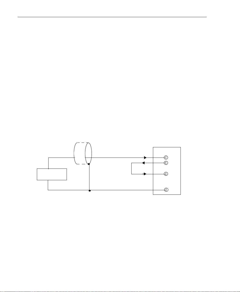
Note that since they measure the difference between the signals at the
high (+) and low (−) inputs, differential connections usually cancel
any common-mode voltages, leaving only the signal. However, if you
are using a grounded signal source and ground loop problems arise,
connect the differential signals as shown as Figure 12. In this case,
make sure that the low side of the signal (−) is connected to ground at
the signal source, not at the screw terminal panel, and do not tie the
two grounds together.
4
4
Screw Terminal Panel
+
Analog In 0
Grounded
Signal
Source
Figure 12: Connecting Differential Voltage Inputs from a Grounded Signal
E
s
Signal Source
Ground V
g1
-
Analog In 0 Return
Analog Ground
Source to a Screw Terminal Panel
1
20
36
It is recommended that
you use the Open
Layers Control Panel
applet to enable 10 k
of resistance to connect
the low side of channel
0 to analog ground (a
physical resistor is not
required). Refer to page
16 for more information.
Ω
4
4
4
4
4
4
4
39
Page 54

Chapter 4
Connecting Current Loop Inputs
Note: You cannot connect a current loop input using the BNC
connectors.
Figure 13 shows how to connect a current loop input (channel 0, in
this case) to your own screw terminal panel.
+V
CC
4 to 20 mA
Analog Input 0
Analog Input 0 Return
Screw Terminal Panel
1
20
User-installed resistor
40
Analog Ground
The user-installed resistor connects the high side of the
channel to the low side of the corresponding channel,
thereby acting as a shunt. For example, if you add a 250
resistor and then connect a 4 to 20 mA current loop input
to channel 0, the input range is converted to 1 to 5 V.
It is recommended that you use the Open Layers Control
Panel applet to enable 10 k
connect the low side of channel 0 to analog ground (a
physical resistor is not required). Refer to page 16 for
more information.
36
Ω of termination resistance to
Figure 13: Connecting Current Inputs to a Screw Terminal Panel
Ω
Page 55

Connecting Analog Output Signals
Figure 14 shows how to connect an analog output voltage signal
(channel 0, in this case) to the BNC connectors on the KUSB-3116
module.
KUSB-3116 Module
Load
Analog Out 0
DAC0
DAC1
DACClock
ADClock
Wiring Signals
4
4
4
DAC2
Note that the BNC box automatically
connects the Analog Ground signal
appropriately.
Figure 14: Connecting Analog Outputs to the BNC Connectors
Figure 15 shows how to connect analog outputs to your own screw
terminal panel.
Analog Output 0
Load
Analog Output 0 Return
Figure 15: Connecting Analog Outputs to a Screw Terminal Panel
DAC3
DACTrig
ADTrig
Screw Terminal Panel
Digital I/O
1
20
C\T, DAC, Clk, Trig
4
4
4
4
4
4
41
Page 56

Chapter 4
Connecting Digital I/O Signals
Figure 16 shows how to connect digital input signals (lines 0 and 1, in
this case) to your own screw terminal panel.
Screw Terminal Panel
Digital Input 0
TTL Inputs
Digital Input 1
Digital Ground
Figure 16: Connecting Digital Inputs to a Screw Terminal Panel
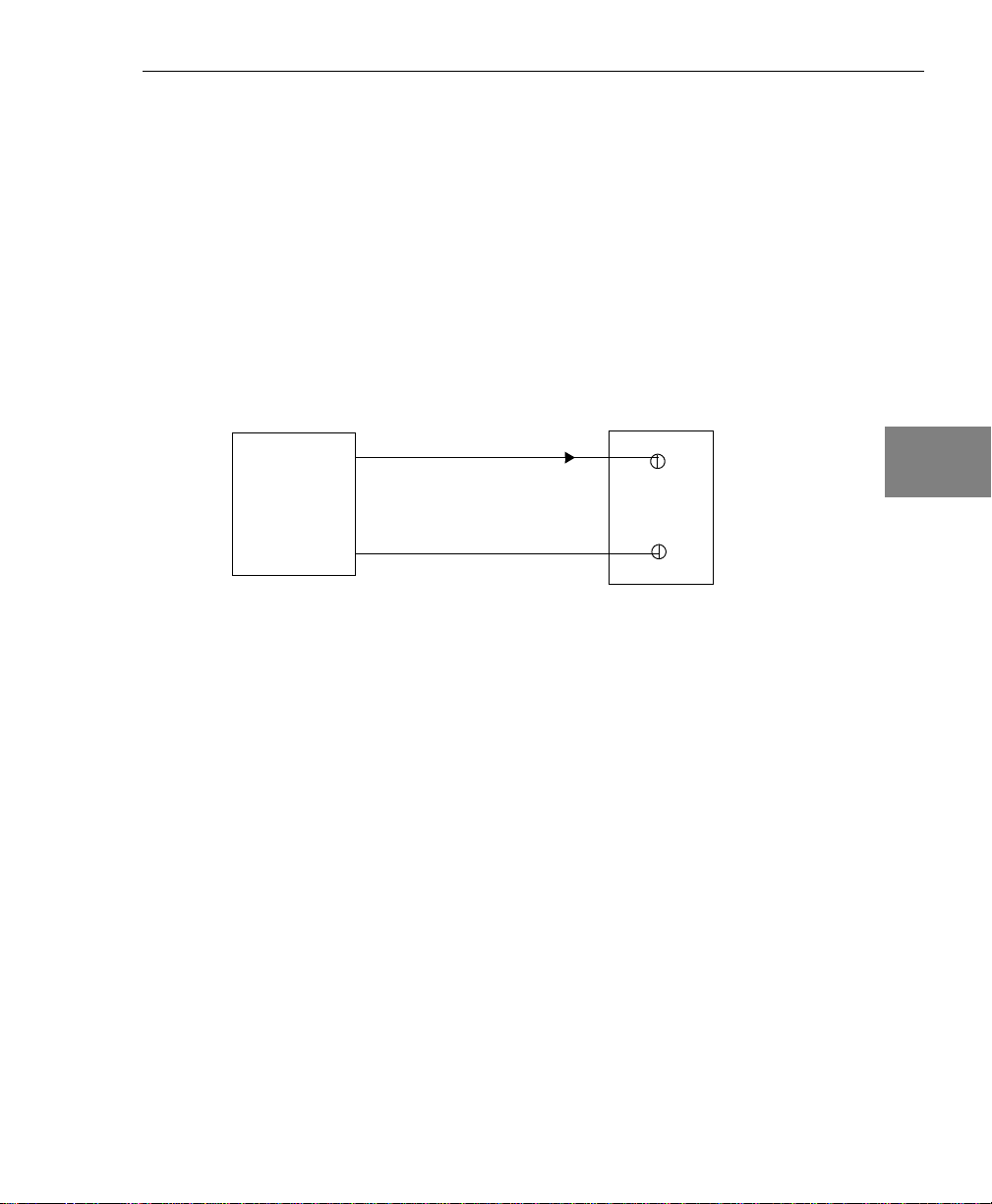
Figure 17 shows how to connect a digital output (line 0, in this case)
to your own screw terminal panel.
Screw Terminal Panel
5 V
0 Out = LED On
500 Ω
+
-
Digital Out 0
Digital Ground
1
2
17
20
37
42
Figure 17: Connecting Digital Outputs to a Screw Terminal Panel
Page 57

Connecting Counter/Timer Signals
The KUSB-3116 module provides five counter/timer channels that
you can use to perform the following operations:
• Event counting,
•Up/down counting,
• Frequency measurement,
Wiring Signals
4
4
• Pulse width/period measurement,
• Edge-to-edge measurement, and
• Pulse output (continuous, one-shot, and repetitive one-shot).
This section describes how to connect counter/timer signals. Refer to
the KUSB-3116 User’s Manual for more information about using the
counter/timers.
Connecting Signals for Event Counting Operations
Figure 18 shows how to connect counter/timer signals either to your
own screw terminal panel to perform an event counting operation on
counter/timer 0 using an external gate. The counter counts the
number of rising edges that occur on the Counter 0 Clock input when
the Counter 0 Gate signal is in the active state (as specified by
software). Refer to the KUSB-3116 User’s Manual for more
information.
4
4
4
4
4
4
4
43
Page 58

Chapter 4
Signal
Source
External
Gating
Switch
Screw Terminal Panel
Counter 0 Clock
Counter 0 Gate
Digital Ground
8
28
29
Digital Ground
31
Figure 18: Connecting Counter/Timer Signals to a Screw Terminal Panel for
an Event Counting Operation Using an External Gate
Figure 19 shows how to connect counter/timer signals either to your
own screw terminal panel to perform an event counting operation on
counter/timer 0 without using a gate. The counter counts the number
of rising edges that occur on the Counter 0 Clock input.
Screw Terminal Panel
Counter 0 Clock
Signal Source
Digital Ground
8
18
Figure 19: Connecting Counter/Timer Signals to a Screw Terminal Panel for
an Event Counting Operation Without Using a Gate
44
Page 59

Connecting Signals for Up/Down Counting Operations
Figure 20 shows how to connect counter/timer signals to your own
screw terminal panel to perform an up/down counting operation on
counter/timer 0. The counter keeps track of the number of rising
edges that occur on the Counter 0 Clock input. The counter
increments when the Counter 0 Gate signal is high and decrements
when the Counter 0 Gate signal is low.
Wiring Signals
4
4
Screw Terminal Panel
Counter 0 Clock
Up/Down
Signal
Source
Figure 20: Connecting Counter/Timer Signals to a Screw Terminal Panel for
an Up/Down Counting Operation
Digital Ground
Counter 0 Gate
8
18
28
4
4
4
4
4
4
4
45
Page 60
Chapter 4
Connecting Signals for Frequency Measurement Operations
One way to measure frequency is to use the same wiring as a
standard event counting application that does not use a gate (see
Figure 19 on page 44), then use the Windows timer to determine the
duration of the frequency measurement. The frequency of the
Counter 0 Clock signal is the number of counts divided by the
duration of the Windows timer.
If you need more accuracy than the Windows timer can provide, you
can connect a pulse of a known duration (such as a one-shot output of
counter/timer 1) to the Counter 0 Gate input. Figure 21 shows how to
connect counter/timer signals to your own screw terminal panel. In
this case, the frequency of the Counter 0 clock input is the number of
counts divided by the period of the Counter 0 Gate input signal.
Screw Terminal Panel
46
Signal Source
Counter 0 Clock
Counter 1 Out
Counter 0 Gate
Digital Ground
8
11
28
33
Figure 21: Connecting Counter/Timer Signals to a Screw Terminal Panel for
a Frequency Measurement Operation Using an External Pulse
Page 61
Connecting Signals for Period/Pulse Width Measurement Operations
Figure 22 shows how to connect counter/timer signals to your own
screw terminal panel to perform a period/pulse width measurement
operation on counter/timer 0. You specify the active pulse (high or
low) in software. The pulse width is the percentage of the total pulse
period that is active. Refer to the KUSB-3116 User’s Manual for more
information about pulse periods and pulse widths.
Screw Terminal Panel
Wiring Signals
4
4
4
Counter 0 Clock
Signal Source
Digital Ground
Figure 22: Connecting Counter/Timer Signals to a Screw Terminal Panel for
a Period/Pulse Width Measurement Operation
8
18
4
4
4
4
4
4
47
Page 62

Chapter 4
Connecting Signals for Edge-to-Edge Measurement Operations
Figure 23 shows how to connect counter/timer signals to your own
screw terminal panel to perform an edge-to-edge measurement
operation on two signal sources. The counter measures the time
interval between the start edge (in this case, a rising edge on the
Counter 0 Clock signal) and the stop edge (in this case, a falling edge
on the Counter 0 Gate signal).
You specify the start edge and the stop edge in software. Refer to the
KUSB-3116 User’s Manual for more information.
Screw Terminal Panel
Signal Source 0
Signal Source 1
Counter 0 Clock
Digital Ground
Counter 0 Gate
8
18
28
Figure 23: Connecting Counter/Timer Signals to a Screw Terminal Panel for
an Edge-to-Edge Measurement Operation
48
Page 63

Wiring Signals
Connecting Signals for Pulse Output Operations
Figure 24 shows how to connect counter/timer signals to your own
screw terminal panel to perform a pulse output operation on
counter/timer 0; in this example, an external gate is used.
Screw Terminal Panel
Counter 0 Out
9
Heater
Controller
Figure 24: Connecting Counter/Timer Signals to a Screw Terminal Panel for
a Pulse Output Operation Using an External Gate
External
Gating
Switch
Counter 0 Gate
Digital Ground
Digital Ground
28
29
33
4
4
4
4
4
4
4
4
4
49
Page 64

Chapter 4
50
Page 65

5
Verifying the Operation
of a Module
Overview . . . . . . . . . . . . . . . . . . . . . . . . . . . . . . . . . . . . . . . . . . . . . . 53
Running the Quick Data Acq Application . . . . . . . . . . . . . . . . . . 54
51
Page 66

Chapter 5
Prepare to Use a Module
(see Chapter 2 starting on page 7)
Set Up and Install the Module
(see Chapter 3 starting on page 13)
Wire Signals to the BNC Connection Box
(see Chapter 4 starting on page 23)
Verify the Operation of the Module
(this chapter)
52
Page 67

Overview
You can verify the operation of a KUSB-3116 module using the Quick
Data Acq application. Quick Data Acq allows you to perform the
following operations:
Verifying the Operation of a Module
5
• Acquire data from a single analog input channel or digital input
port;
• Acquire data continuously from one or more analog input
channels using an oscilloscope, strip chart, or Fast Fourier
Transform (FFT) view;
• Measure the frequency of events;
• Output data from a single analog output channel or digital
output port;
• Output pulses either continuously or as a one-shot; and
• Save the input data to disk.
Quick Data Acq is installed automatically when you install the driver
software, described on page 9.
5
5
5
5
5
5
5
5
53
Page 68

Chapter 5
Running the Quick Data Acq Application
To run the Quick Data Acq application, perform the following steps:
1. If you have not already done so, power up your computer and
any attached peripherals.
2. Select Quick Data Acq from the Keithley Instruments\Quick
Data Acq program group.
Note: The Quick Data Acq application allows you to verify basic
operations on the module; however, it may not support all of the
module’s features. For information about each of the supported
features, use the online help for the Quick Data Acq application by
pressing F1 from any view or selecting the Help menu, or refer to the
KUSB-3116 User’s Manual.
Performing a Single-Value Analog Input Operation
54
To verify that the module can read a single analog input value,
perform the following steps:
1. Connect a voltage source, such as a function generator, to analog
input channel 0 (differential mode) on the KUSB-3116 module.
Refer to page 37 for an example of how to connect a differential
analog input.
2. Click the Acquisition menu.
3. Click Single Analog Input.
4. Select the appropriate KUSB-3116 module from the Board list
box.
5. In the Channel list box, select analog input channel 0.
6. In the Range list box, select the range for the channel. The default
is ±10 V.
Page 69

7. Select Differential.
Verifying the Operation of a Module
8. Click Get to acquire a single value from analog input channel 0.
The value is displayed on the screen in both text and graphical form.
Performing a Single-Value Analog Output Operation
To verify that the module can output a single analog output value,
perform the following steps:
1. Connect an oscilloscope or voltmeter to analog output channel 0
on the module. Refer to page 41 for an example of how to connect
analog output signals.
2. Click the Control menu.
3. Click Single Analog Output.
4. Select the appropriate KUSB-3116 module from the Board list
box.
5. In the Channel list box, select analog output channel 0.
6. In the Range list box, select the output range of DAC0. The
default is ±10 V.
7. Enter an output value, or use the slider to select a value, to output
from DAC0.
5
5
5
5
5
5
8. Click Send to output a single value from analog output
channel 0.
The value that is output is displayed both on the slider and in the text
box.
5
5
5
55
Page 70

Chapter 5
Performing a Continuous Analog Input Operation
To verify that the module can perform a continuous analog input
operation, perform the following steps:
1. Connect known voltage sources, such as the outputs of a function
generator, to analog input channels 0 and 1 on the KUSB-3116
module (differential mode). Refer to page 37 for an example of
how to connect a differential analog input.
2. Click the Acquisition menu.
3. For this example, click Scope.
4. Select the appropriate KUSB-3116 module from the Board list
box.
5. In the Sec/Div list box, select the number of seconds per division
(.1 to .00001) for the display.
6. In the Channel list box, select analog input channel 1, then click
Add to add the channel to the channel list. Note that, by default,
channel 0 is included in the channel list.
56
7. Click Config from the Toolbar.
8. From the Config menu, select ChannelType, then select
Differential.
9. From the Config menu, select Range then select Bipolar.
10. Click OK to close dialog box
11. From the Scope view, double-click the input range of the channel
to change the input range of the module (±10 V, ±5 V, ±2.5 V, or
±1.25 V). The default is ±10 V.
The display changes to reflect the selected range for all the analog input
channels on the module.
12. In the Tr ig g e r box, select Auto to acquire data continuously from
the specified channels or Manual to acquire a burst of data from
the specified channels.
Page 71

Verifying the Operation of a Module
13. Click Start from the Toolbar to start the continuous analog input
operation.
The values acquired from each channel are displayed in a unique color
on the oscilloscope view.
14. Click Stop from the Toolbar to stop the operation.
Performing a Single-Value Digital Input Operation
5
5
To verify that the module can read a single digital input value,
perform the following steps:
1. Connect a digital input to digital input line 0 on the KUSB-3116
module. Refer to page 42 for an example of how to connect a
digital input.
2. Click the Acquisition menu.
3. Click Digital Input.
4. Select the appropriate KUSB-3116 module from the Board list
box.
5. Click Get.
The entire 16-bit digital input value (0 to FFFF) is displayed in both the
Data box and the Digital Input box.
In addition, the state of the lower eight digital input lines (lines 0 to 7)
is shown in the graphical display. If an indicator light is lit (red), the
line is high; if an indicator light is not lit (black), the line is low.
Note: Although the KUSB-3116 module contains 16 digital
input lines, the Quick Data Acq application shows indicator
lights for the lower eight digital input lines only. The 16-bit value
is the correct value for all 16 lines.
5
5
5
5
5
5
5
57
Page 72

Chapter 5
Performing a Single-Value Digital Output Operation
Note: Although the KUSB-3116 module contains 16 digital output
lines, the Quick Data Acq application allows you to perform a digital
output operation on the lower eight digital output lines (lines 0 to 7)
only.
To verify that the module can output a single digital output value,
perform the following steps:
1. Connect a digital output to digital output line 0 on the
KUSB-3116 module. Refer to page 42 for an example of how to
connect a digital output.
2. Click the Control menu.
3. Click Digital Output.
4. Select the appropriate KUSB-3116 module from the Board list
box.
58
5. Click the appropriate indicator lights to select the types of signals
to write from the digital output lines. If you select a light, the
module outputs a high-level signal; if you do not select a light,
the module outputs a low-level signal. You can also enter an
output value for the lower eight digital output lines (0 to FF) in
the Hex text box.
6. Click Send.
The values of the lower eight digital output lines are output
appropriately.
Page 73

Verifying the Operation of a Module
Performing a Frequency Measurement Operation
To verify that the module can perform a frequency measurement
operation, perform the following steps:
1. Wire an external clock source to counter/timer 0 on the
KUSB-3116 module. Refer to page 59 for an example of how to
connect an external clock.
Note: The Quick Data Acq application works only with
counter/timer 0.
2. Click the Acquisition menu.
3. Click Measure Frequency.
4. Select the appropriate KUSB-3116 module from the Board list
box.
5. In the Count Duration text box, enter the number of seconds
during which events will be counted.
6. Click Start to start the frequency measurement operation.
The operation automatically stops after the number of seconds you
specified has elapsed, and the frequency is displayed on the screen.
5
5
5
5
5
5
7. Click Stop to stop the frequency measurement operation.
5
5
5
59
Page 74

Chapter 5
Performing a Pulse Output Operation
To verify that the module can perform a pulse output operation,
perform the following steps:
1. Connect a scope to counter/timer 0 on the KUSB-3116 module.
Refer to page 49 for an example of how to connect a scope (a
pulse output) to counter/timer 0.
Note: The Quick Data Acq application works only with
counter/timer 0.
2. Click the Control menu.
3. Click Pulse Generator.
4. Select the appropriate KUSB-3116 module from the Board list
box.
5. Select either Continuous to output a continuous pulse stream or
One Shot to output one pulse.
60
6. Select either Low-to-high to output a rising-edge pulse (the high
portion of the total pulse output period is the active portion of
the signal) or High-to-low to output a falling-edge pulse (the low
portion of the total pulse output period is the active portion of
the signal).
7. Under Pulse Width, enter a percentage or use the slider to select
a percentage for the pulse width. The percentage determines the
duty cycle of the pulse.
8. Click Start to generate the pulse(s).
The results are displayed both in text and graphical form.
9. Click Stop to stop a continuous pulse output operation. One-shot
pulse output operations stop automatically.
Page 75

A
Ground, Power, and Isolation
Connections
61
Page 76
Appendix A
+5 V USB; used for
initialization only, not
for power.
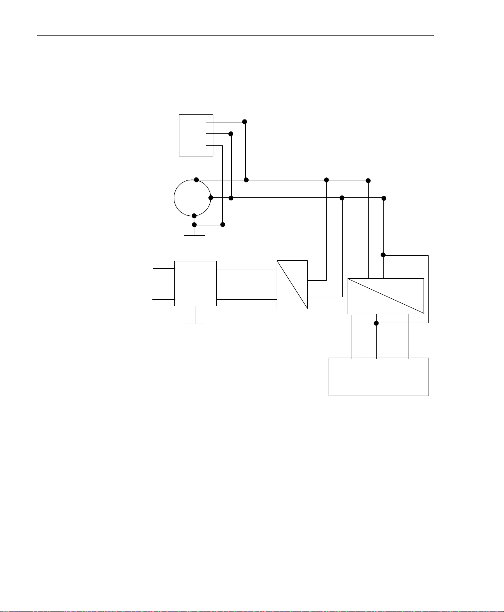
Figure 25 illustrates how ground, power, and isolation are connected
internally on a KUSB-3116 module.
1
TB1
USB
2
3
USB Interface
Powe r
+5 V
DGND
DC
DC
DC
+5 V
+5 V
Earth GND
Interface
DGND USB
DC
62
Earth GND
A/D and D/A
Powe r
A/D and D/A
System
Figure 25: Ground, Power, and Isolation Connections
AGND-15 V +15 V
Page 77

Keep the following in mind:
Ground, Power, and Isolation Connections
• Earth ground on the KUSB-3116 module is not connected to
DGND or AGND.
• Earth ground is connected to the aluminum case of the BNC
connection box.
• You should connect earth ground to the power supply earth.
• You should isolate the +5V/DGND input. Note that the power
supply (shipped with the KUSB-3116 module) has no connection
between +5V/DGND and earth ground.
• The USB connector case is connected to earth ground.
• The USB data lines and USB GND are not connected to earth
ground.
• The USB DGND is connected to the USB GND of the PC USB
port.
A
A
A
A
A
A
A
A
A
63
Page 78

Appendix A
64
Page 79

Index
A
analog inputs 54, 56
current loops 40
differential configuration 33, 37
pseudo-differential configuration 33
single-ended configuration 33, 34
wiring 33
analog outputs 41, 55
applet, Open Layers Control Panel 10
application wiring
analog outputs 41
current loop analog inputs 40
differential analog inputs 37
digital inputs and outputs 42
edge-to-edge measurement 48
event counting 43
frequency measurement 46
period measurement 47, 48
pseudo-differential analog inputs 35
pulse output 49
pulse width measurement 47
single-ended analog inputs 34
up-down counting 45
applying power 15
attaching the module to the computer
18
B
bias return resistance 16, 37
C
cables, USB 18, 20
configuring the device driver 16
connecting signals
analog outputs 41
current loop analog inputs 40
differential analog inputs 37
digital inputs and outputs 42
edge-to-edge measurement 48
event counting 43
frequency measurement 46
period measurement 47, 48
pseudo-differential analog inputs 35
pulse output 49
pulse width measurement 47
single-ended analog inputs 34
up-down counting 45
connecting to the host computer 18
using an expansion hub 20
connector J2 pin assignments 31
Control Panel applet 10
conventions used xii
counter/timers
connecting edge-to-edge signals 48
connecting event counting signals 43
connecting frequency measurement
signals
connecting period signals 47
connecting pulse output signals 49
connecting pulse width signals 47
connecting up-down counting
signals
46
45
65
Page 80

Index
current loop inputs 40
D
DataAcq SDK 4
device driver 4, 16
differential inputs 33
Digital In/Out connector pin
assignments
digital inputs 42, 57
digital outputs 42, 58
DT-LV Link 4
DTx-EZ 4
30
E
edge-to-edge measurement, wiring 48
event counting, wiring 43
F
frequency measurement 46, 59
G
ground 62
H
help, online 54
hot-swapping 18
I
input configuration
differential analog 33
pseudo-differential analog 33
single-ended analog 33
installing the software 11
isolation 62
J
J2 connector pin assignments 31
L
LEDs 18, 20
O
online help 54
Open Layers Control Panel applet 10
output pulses 49, 60
P
period measurement, wiring 47, 48
pin assignments, Digital In/Out
connector
power 15, 62
power supply 15
preparing to wire signals 25
pseudo-differential inputs 33
pulse outputs 49, 60
pulse width measurement, wiring 47
30
Q
Quick Data Acq application 4
running 54
R
recommendations for wiring 25
related documents xii
66
Page 81

requirements 10
running the Quick Data Acq
application
54
S
single-ended inputs 33
software supported 4
system requirements 10
U
unpacking 9
up-down counting, wiring 45
USB cable 18, 20
W
wiring signals
analog outputs 41
current loop analog inputs 40
differential analog inputs 37
digital inputs and outputs 42
edge-to-edge measurement 48
event counting 43
frequency measurement 46
methods 26
period measurement 47, 48
preparing 25
pseudo-differential analog inputs 35
pulse output 49
pulse width measurement 47
recommendations 25
single-ended analog inputs 34
to the BNCs 26
up-down counting 45
Index
67
Page 82

Index
68
Page 83

All Keithley trademarks and trade names are the property of Keithley Instruments, Inc.
Specifications are subject to change without notice.
All other trademarks and trade names are the property of their respective companies.
Corporate Headquar
A GR
EA
TER M
EASU
E OF C
R
ONFIDENCE
Keithley Instruments, Inc.
39 • 440-248-0400 • Fax: 440-248-6168 • 1-888-KEITHLEY (534-8453) • www.keithley.com
5 Aurora Road • Cleveland, Ohio 44
7
ers
7
t
8
• 2
1
12/04
 Loading...