

Page 1

DPP-25 and DPP-45 Series Printers
User’s Guide
Page 2

DPP-25 and DPP-45 Series Printers
User’s Guide
Revision A - March 1996
Part Number: 40420
Page 3

New Contact Information
Keithley Instruments, Inc.
28775 Aurora Road
Cleveland, OH 44139
Technical Support: 1-888-KEITHLEY
Monday – Friday 8:00 a.m. to 5:00 p.m (EST)
Fax: (440) 248-6168
Visit our website at http://www.keithley.com
Page 4

The information contained in this manual is believed to be accurate and reliable. However, Keithley
Instruments, Inc., assumes no responsibility for its use or for any infringements of patents or other rights
of third parties that may result from its use. No license is granted by implication or otherwise under any
patent rights of Keithley Instruments, Inc.
KEITHLEY INSTRUMENTS, INC., SHALL NOT BE LIABLE FOR ANY SPECIAL, INCIDENTAL,
OR CONSEQUENTIAL DAMAGES RELATED TO THE USE OF THIS PRODUCT. THIS
PRODUCT IS NOT DESIGNED WITH COMPONENTS OF A LEVEL OF RELIABILITY
SUITABLE FOR USE IN LIFE SUPPORT OR CRITICAL APPLICATIONS.
Refer to your Keithley Instruments license agreement for specific warranty and liability information.
All brand and product names are trademarks or registered trademarks of their respective companies.
© Copyright Keithley Instruments, Inc., 1996.
All rights reserved. Reproduction or adaptation of any part of this documentation beyond that permitted
by Section 117 of the 1976 United States Copyright Act without permission of the Copyright owner is
unlawful.
Acculex
A Unit of Keithley Instruments, Inc.
440 Myles Standish Blvd. Taunton, MA 02780
Telephone: (508) 880-3660 ● FAX: (508) 880-0179
Page 5

Preface
This document describes the features and operation of the DPP-25 and
DPP-45 Series printers.
The manual is intended for users responsible for setting up, installing, and
operating these printers.
The DPP-25 and DPP-45 Series User’s Guide is organized as follows:
● Chapter 1 provides an overview of the features, specifications, and
dimensions of the DPP-25 and DPP-45 Series printers.
● Chapter 2 describes how to set up the printers.
● Chapter 3 describes how to operate the printers.
● Chapter 4 describes how to change the configuration of the printers.
An index completes this manual.
v
Page 6

Table of Contents
Preface
1 Overview
Features . . . . . . . . . . . . . . . . . . . . . . . . . . . . . . . . . . . . . . . . . . . .1-1
Specifications . . . . . . . . . . . . . . . . . . . . . . . . . . . . . . . . . . . . . . . .1-3
Dimensions. . . . . . . . . . . . . . . . . . . . . . . . . . . . . . . . . . . . . . . . . .1-3
2 Setting up the Printer
Connecting I/O Devices to the Printer. . . . . . . . . . . . . . . . . . . . .2-1
Connecting Power to the Printer . . . . . . . . . . . . . . . . . . . . . . . . .2-2
Loading or Changing the Paper Roll . . . . . . . . . . . . . . . . . . . . . .2-3
Changing the Ribbon Cartridge . . . . . . . . . . . . . . . . . . . . . . . . . .2-6
Mounting the Printer . . . . . . . . . . . . . . . . . . . . . . . . . . . . . . . . . .2-7
3 Operating the Printer
Performing a Self Test . . . . . . . . . . . . . . . . . . . . . . . . . . . . . . . . .3-1
Using Control Codes . . . . . . . . . . . . . . . . . . . . . . . . . . . . . . . . . .3-2
Using Escape Sequences . . . . . . . . . . . . . . . . . . . . . . . . . . . . . . .3-3
Using Bit Image Graphics Mode . . . . . . . . . . . . . . . . . . . . . . . . .3-4
4 Changing the Printer Configuration
Locating the Components . . . . . . . . . . . . . . . . . . . . . . . . . . . . . .4-1
Connecting Power - P1. . . . . . . . . . . . . . . . . . . . . . . . . . . . . . . . .4-3
Feeding the Paper, Resetting the Printer, or Performing a
Self Test - P3 . . . . . . . . . . . . . . . . . . . . . . . . . . . . . . . . . . . . . . . .4-4
Changing the Communication Parameters - SW1
(Serial Printers Only) . . . . . . . . . . . . . . . . . . . . . . . . . . . . . . . . .4-5
Connecting I/O - P4 . . . . . . . . . . . . . . . . . . . . . . . . . . . . . . . . . . .4-6
RS-232 Serial Interface. . . . . . . . . . . . . . . . . . . . . . . . . . . . . .4-7
Centronics and Parallel Interfaces. . . . . . . . . . . . . . . . . . . . . .4-8
Index
iii
Page 7

List of Figures
Figure 1-1. Printer Model Numbers . . . . . . . . . . . . . . . . . . . . .1-2
Figure 1-2. Printer Dimensions (Front View without Front
Cover) . . . . . . . . . . . . . . . . . . . . . . . . . . . . . . . . . .1-4
Figure 1-3. Printer Dimensions (Rear View with Cover). . . . .1-5
Figure 1-4. Printer Dimensions (Side View without
Rear Cover) . . . . . . . . . . . . . . . . . . . . . . . . . . . . . .1-6
Figure 1-5. Printer Dimensions (Side View with Rear Cover).1-7
Figure 2-1. Connecting to the Printer. . . . . . . . . . . . . . . . . . . .2-2
Figure 2-2. Removing the Front Cover . . . . . . . . . . . . . . . . . .2-3
Figure 2-3. Removing the Paper Spindle . . . . . . . . . . . . . . . . .2-3
Figure 2-4. Loading the Paper into the Paper Feed
Mechanism. . . . . . . . . . . . . . . . . . . . . . . . . . . . . . .2-4
Figure 2-5. Feeding the Paper through the Paper Feed
Mechanism. . . . . . . . . . . . . . . . . . . . . . . . . . . . . . .2-4
Figure 2-6. Replacing the Spindle . . . . . . . . . . . . . . . . . . . . . .2-5
Figure 2-7. Feeding Paper through the Front Cover. . . . . . . . .2-5
Figure 2-8. Ejecting the Ribbon Cartridge . . . . . . . . . . . . . . . .2-6
Figure 2-9. Mounting the Printer . . . . . . . . . . . . . . . . . . . . . . .2-7
Figure 4-1. Rear View of Serial Printers . . . . . . . . . . . . . . . . .4-2
Figure 4-2. Rear View of the Centronics and Parallel Printers 4-2
Figure 4-3. Serial Timing . . . . . . . . . . . . . . . . . . . . . . . . . . . . .4-7
Figure 4-4. Centronics and Parallel Timing . . . . . . . . . . . . . . .4-9
List of Tables
Table 1-1. General Specifications. . . . . . . . . . . . . . . . . . . . . .1-3
Table 3-1. Control Codes . . . . . . . . . . . . . . . . . . . . . . . . . . . .3-2
Table 3-2. Escape Sequences . . . . . . . . . . . . . . . . . . . . . . . . .3-3
Table 4-1. P1 - Power Connector Pin Assignments . . . . . . . .4-3
Table 4-2. P3 - Paper Feed and Reset Connector
Pin Assignments . . . . . . . . . . . . . . . . . . . . . . . . . .4-4
Table 4-3. DIP Switch Settings (Serial Printers Only) . . . . . .4-5
Table 4-4. Baud Rate Settings. . . . . . . . . . . . . . . . . . . . . . . . .4-6
Table 4-5. P4 Connector, RS-232 Interface Pin Assignments 4-7
Table 4-6. P4 Connector, Centronics and Parallel Interfaces .4-8
iv
Page 8

Table 1-1. General Specifications. . . . . . . . . . . . . . . . . . . . . .1-3
Table 3-1. Control Codes . . . . . . . . . . . . . . . . . . . . . . . . . . . .3-2
Table 3-2. Escape Sequences . . . . . . . . . . . . . . . . . . . . . . . . .3-3
Table 4-1. P1 - Power Connector Pin Assignments . . . . . . . .4-3
Table 4-2. P3 - Paper Feed and Reset Connector
Pin Assignments4-4
Table 4-3. DIP Switch Settings (Serial Printers Only) . . . . . .4-5
Table 4-4. Baud Rate Settings. . . . . . . . . . . . . . . . . . . . . . . . .4-6
Table 4-5. P4 Connector, RS-232 Interface Pin Assignments 4-7
Table 4-6. P4 Connector, Centronics and Parallel Interfaces .4-8
Page 9

Figure 1-1. Printer Model Numbers . . . . . . . . . . . . . . . . . . . . .1-2
Figure 1-2. Printer Dimensions (Front View without Front Cover)
1-4
Figure 1-3. Printer Dimensions (Rear View with Cover). . . . .1-5
Figure 1-4. Printer Dimensions (Side View without Rear Cover)
1-6
Figure 1-5. Printer Dimensions (Side View with Rear Cover).1-7
Figure 2-1. Connecting to the Printer. . . . . . . . . . . . . . . . . . . .2-2
Figure 2-2. Removing the Front Cover . . . . . . . . . . . . . . . . . .2-3
Figure 2-3. Removing the Paper Spindle . . . . . . . . . . . . . . . . .2-3
Figure 2-4. Loading the Paper into the Paper Feed Mechanism .
2-4
Figure 2-5. Feeding the Paper through the Paper Feed Mechanism
2-4
Figure 2-6. Replacing the Spindle . . . . . . . . . . . . . . . . . . . . . .2-5
Figure 2-7. Feeding Paper through the Front Cover. . . . . . . . .2-5
Figure 2-8. Ejecting the Ribbon Cartridge . . . . . . . . . . . . . . . .2-6
Figure 2-9. Mounting the Printer . . . . . . . . . . . . . . . . . . . . . . .2-7
Figure 4-1. Rear View of Serial Printers . . . . . . . . . . . . . . . . .4-2
Figure 4-2. Rear View of the Centronics and Parallel Printers 4-2
Figure 4-3. Serial Timing . . . . . . . . . . . . . . . . . . . . . . . . . . . . .4-7
Figure 4-4. Centronics and Parallel Timing . . . . . . . . . . . . . . .4-9
Page 10

Features
1
Overview
This chapter describes the features, general specifications, and
dimensions of the DPP-25 and DPP-45 Series printers.
The DPP-25 and DPP-45 Series printers provide the following standard
features:
● 5 VDC input power operation.
● 6912 Character input buffer.
● Paper feed/reset/self-test input.
● Normal or inverted print.
● Underlined text.
● Double-wide, double-high, or double-wide AND double-high
characters. You can mix normal and double-wide characters on any
line.
● Bit image graphics mode using the EPSON line printer, ESC K
protocol.
● Fast paper feed through the Paper Feed switch or through the
"immediate feed command" (ESC J +n).
● Serial RS-232 interface, available on the DPP-25xxS and DPP-45xxS
printers.
Features 1-1
Page 11

● Centronics interface, available on the DPP-25xxC and DPP-45xxC
printers.
● Parallel interface, available on the DPP-25xxP and DPP-45xxP
printers.
The following features are optional:
● 12 VDC power input (includes a linear regulator), available on the
DPP-2512x and DPP-4512x printers.
● 120 VAC power input (includes the linear regulator and a 14 VAC,
20 VA wall mount transformer), available on the DPP-25ACx and
DPP-AC12x printers.
The interface type and the power input used are indicated in the model
number for the printer, as shown in Figure 1-1.
For example, a DPP-25 Series printer with the 12 VDC power input and
the RS-232 serial interface is model number DPP-2512S. A DPP-45
Series printer with the 5 VDC power input and the parallel interface is
model number DPP-4505P.
DPP-25xxx
C = Centronics
5 VDC = 05
12 VDC = 12
120 VAC = AC
P = Parallel
S = Serial
DPP-45xxx
C = Centronics
5 V DC = 05
12 V DC = 12
120 VAC = AC
Figure 1-1. Printer Model Numbers
1-2 Overview
P = Parallel
S = Serial
Page 12
Specifications
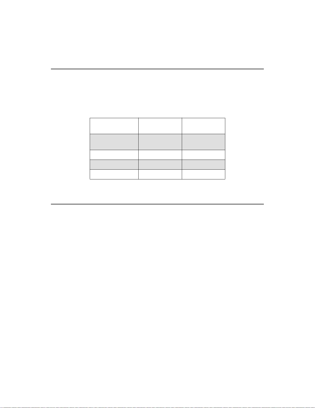
Table 1-1 lists the general specifications of the DPP-25 and DPP-45
Series printers.
Table 1-1. General Specifications
Feature DPP-25 Series
Paper Width 57.5 mm
Dots per line 166 252
Characters per line 24 42
Lines per second 1.7 1.0
Dimensions
DPP-45 Series
Specifications
2.25 inches
Specifications
57.5 mm
2.25 inches
Figure 1-2 shows the dimensions of the printers from the front with the
front cover removed. Figure 1-3 shows the dimensions of the printers
from the rear with the rear cover installed. Figure 1-4 shows the
dimensions of the printers from the side with the rear cover removed.
Figure 1-5 shows the dimensions of the printers from the side with the
rear cover installed.
Specifications 1-3
Page 13
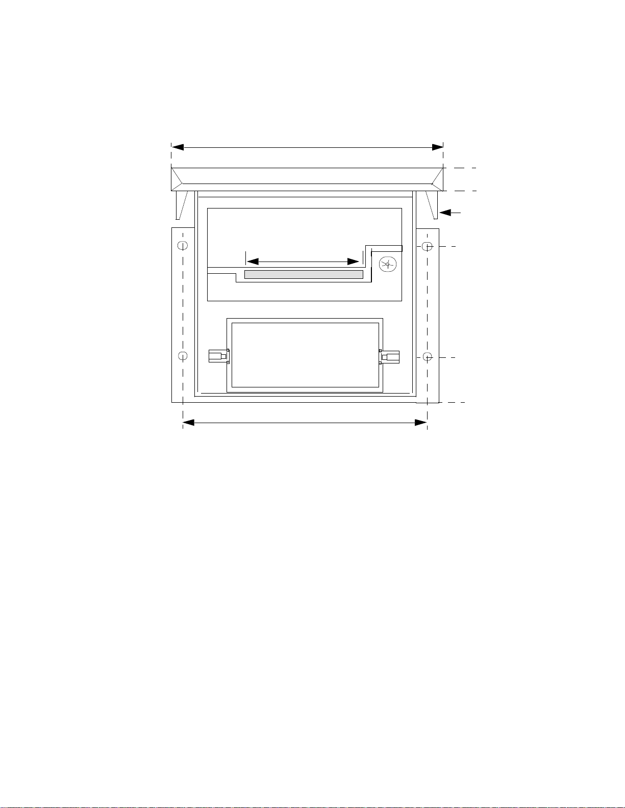
4.50
4.350
4.0 (Ref)
Printer Mechanism
Paper Path
Ribbon Cartridge
Paper Roll
Paper Roll
4.125
Figure 1-2. Printer Dimensions (Front View without Front Cover)
Latch
Cover
2.720
0.920
0.0
1-4 Overview
Page 14

3.375 inches
1.55
inches
Paper Feed Switch
(Wiring Access)
25-pin Serial or
Parallel
Connector
(depends on
printer)
36-pin,
Centronics
Connector
Not used
Power
Jack
3.775
inches
4-40 Screws
(4 PLCS)
DIP Switch
Access (on serial
printers only)
Figure 1-3. Printer Dimensions (Rear View with Cover)
Dimensions 1-5
Page 15

3.8 Ref
0.0
Panel Mounting
Plane
1.65
3.50
Behind Panel Depth to
Allow Cable Access
Figure 1-4. Printer Dimensions (Side View without Rear Cover)
1-6 Overview
Page 16

Behind Panel Dimensions
3.45-inches with 25-pin, Sub D Serial Connector
3.60-inches with 36-pin, Parallel Connector
Printer Case
Panel Mounting
Plane
Printer
Cover
Printer
Cover
User-supplied
cable
Figure 1-5. Printer Dimensions (Side View with Rear Cover)
Dimensions 1-7
Page 17

Setting up the Printer
This chapter describes how to set up the printer, including how to
● Connect an I/O device to the printer
● Connect power to the printer
● Load or change the paper roll
● Change the ribbon cartridge
● Mount the printer in a panel
Refer to Chapter 3 for information on how to operate the printer; refer to
Chapter 4 for information on how to change the printer configuration.
Connecting I/O Devices to the Printer
2
Refer to Figure 2-1 for the location of the I/O connectors on the printer.
If you are using a serial printer, connect the 25-pin, male connector end of
the serial cable to the I/O connector on the rear panel of the printer;
connect the other end to the I/O device.
If you are using a Centronics printer, connect the 36-pin, male connector
end of the cable to the I/O connector on the rear panel of the printer;
connect the other end to the I/O device.
If you are using a parallel printer, connect the 25-pin, female connector
end of the cable to the I/O connector on the rear panel of the printer;
connect the other end to the I/O device.
Connecting I/O Devices to the Printer 2-1
Page 18

25-pin Serial or
Parallel
Connector
(depends on
printer)
36-pin,
Centronics
Connector
Figure 2-1. Connecting to the Printer
Connecting Power to the Printer
1. Attach the red and black wires of the supplied power cord to the
corresponding terminals of the appropriate power supply:
Power
Jack
– 5 VDC power supply for printer models DPP-2505x and
DPP-4505x
– 12 VDC power supply for printer models DPP-2512x and
DPP-4512x
– 120 VAC power supply for printer models DPP-25ACx and
DPP-45ACx
2. Insert the other end of the power cord into the power jack on the rear
panel of the printer, as shown in Figure 2-1.
2-2 Setting up the Printer
Page 19

Loading or Changing the Paper Roll
To load or change the paper roll, perform the following steps:
1. Slide the front cover down as far as it will go (about 1/2 inch), as
shown in Figure 2-2, and lift it off.
Front Cover
Figure 2-2. Removing the Front Cover
2. Locating the paper roll, use a rotating motion to lift first the left then
the right end of the paper spindle, as shown in Figure 2-3.
Slide down
1/2 inch from top
and lift off
Paper Roll
Paper
Remove left side
of spindle first
Paper Spindle
Right side of
spindle
Figure 2-3. Removing the Paper Spindle
Loading or Changing the Paper Roll 2-3
Page 20

3. Insert the end of the new roll of paper into the paper slot of the printer
mechanism with the paper coming off the roll at the bottom, as shown
in Figure 2-4.
Top of paper feed
Insert paper
in paper
feed
mechanism
Feed paper from
bottom of roll
mechanism
Silver paper feed
guide
Figure 2-4. Loading the Paper into the Paper Feed Mechanism
4. With power supplied to the printer, press the Paper Feed switch until
at least 3 inches of paper extend above the printer, as shown in
Figure 2-5.
Press the Paper Feed
switch until the paper
extends at least
3 inches through the
top of the paper feed
mechanism.
Figure 2-5. Feeding the Paper through the Paper Feed Mechanism
5. Slide the spindle into the new paper roll, being sure that the end with
two shafts is on the left.
2-4 Setting up the Printer
Page 21

6. Place the spindle into its holder by inserting the right side first,
followed by the left side, as shown in Figure 2-6.
Ensure that the left side snaps into place.
Paper Roll
Paper
Replace right side
of spindle first
Figure 2-6. Replacing the Spindle
7. Feed the loose end of paper through the paper slot of the front cover
and rest the cover flush on the base, 1/2 inch from the top, as shown in
Figure 2-7.
Feed paper
through the
front cover
Paper
Slide cover up
until closed
Figure 2-7. Feeding Paper through the Front Cover
8. Slide the front cover up and snap it into position.
Loading or Changing the Paper Roll 2-5
Page 22

Changing the Ribbon Cartridge
Note: Ignore this section unless your ribbon cartridge needs to be
replaced.
To change the ribbon cartridge, perform the following steps:
1. Remove the front cover, as shown in Figure 2-2 on page 2-3.
2. With at least 3 inches of paper extending from the printer, press down
on the left end of the ribbon cartridge to eject it, as shown in Figure
2-8.
Paper Feed
Mechanism
Ribbon cartridge;
push this side to
eject
Paper Roll
Paper
Turn knob to
adjust ribbon
tension
Figure 2-8. Ejecting the Ribbon Cartridge
3. Lift both ends of the ribbon cartridge to remove it.
4. Lower the new ribbon cartridge over the extended paper, turning the
knob on the right end of the ribbon cartridge, as needed, to keep the
ribbon tight.
5. Snap the new ribbon cartridge in place.
6. Replace the front cover as shown in Figure 2-5 on page 2-4.
2-6 Setting up the Printer
Page 23

Mounting the Printer
If you want to mount the printer into a panel, ensure that you choose a
convenient location on the front panel for the Paper Feed switch. Figure
2-9 shows the dimensions required to mount the printer.
0.076 diameter
hole for 2-56
self-tapping screws
(supplied)
0.089 diameter
clearance hole for
2-56 machine
screws (optional)
TYP (4 PLCS)
Use a .50 diameter hole to mount the
supplied Paper Feed switch
3.950
2.66
Printer Cutout
0.860
4.125
4.038
3.95
Ref
0.0
0.0
0.088
Figure 2-9. Mounting the Printer
Mounting the Printer 2-7
Page 24

Operating the Printer
This chapter describes how to operate the printer, including how to
● Perform a self test
● Use control codes
● Use escape sequences
● Use binary image graphics mode
Performing a Self Test
The self-test feature prints the version of the software installed, the model
of the printer connected, various setup parameters (such as the interface
type and communication parameters), followed by the entire alphabet.
3
To perform the self test, press the Paper Feed switch when turning on
power or use the ESC T command, described on page 3-3.
Performing a Self Test 3-1
Page 25

Using Control Codes
Table 3-1 describes the codes you can use to control the DPP-25 and
DPP-45 Series printers.
Table 3-1. Control Codes
Hexadecimal
Value
0A 10 LF Prints the contents of the printer buffer without moving
0D 13 CR Prints the contents of the printer buffer, moves the
0E 14 SO Sets double-wide1 print mode for text. Single-wide and
0F 15 SI Sets double-high2 print mode for text and/or bit image
14 20 DC4 Clears double-wide print mode.
15 21 NAK Clears double-high print mode.
Decimal
Value Name Description
the column pointer, and clears double-high mode.
column pointer to the left margin, and clears double-high
mode.
double-wide print can be intermixed on any print line.
Double-wide stays in effect until the clear double-wide
command is received.
graphics (see page 3-4). Double-high printing is on a
line-by-line basis. The line is single-high or double-high
depending on the mode when a line is printed.
Double-high print mode is cleared when the clear
double-high command is received or whenever a line is
printed. The print can be due to any of the print
commands or to a line length overflow.
1B 27 ESC Escapes header. See the next section for more
information.
Notes
1
You can mix double-wide and normal-wide characters on any line.
2
Double-high print mode causes the entire line to be double high.
3-2 Operating the Printer
Page 26

Using Escape Sequences
An escape sequence is the ESC character immediately followed by the
appropriate byte(s) to complete the sequence, where +n refers to another
byte and +s refers to more than 1 byte to complete the command
sequence. Abbreviations used are as follows:
● NC = Number Of Characters per line
● ND = Number Of Dots per line
● DL = Dot Line
● CL = Character Line
● LM = Left Margin (default = 1)
● RM = Right Margin (default = NC)
● BI = Bit Image graphics
The escape sequences supported by the DPP-25 and DPP-45 Series
printers are described in Table 3-2.
Table 3-2. Escape Sequences
Hexadecimal
Value
Decimal
Value Name Description
+n 20 32 (sp) Tabs to character position n. Range = 1 to RM.
This command is ignored if n is out of range. n is for
single-wide character positions even if double-wide mode
is selected at the time.
+n 24 36 $ Tabs to dot position n. Range = 1 to RM*6. This command
is ignored if n is out of range.
1
+n 2D 45 - Selects underline mode. OFF is n=0 , ON is n=1.
30 48 0 Sets line spacing to 9 DL/CL (default).
31 49 1 Sets line spacing to 8 DL/CL (no BI space).
32 50 2 Sets line spacing to 12 DL/CL.
40 64 @ Initializes printer.
Using Escape Sequences 3-3
Page 27

Table 3-2. Escape Sequences (cont.)
Hexadecimal
Value
+n 41 65 A Sets line spacing to n DL/CL.
+n 43 67 C Causes a pause while the controller tries to activate an
+n 4A 74 J Prints, if needed, then fast feeds paper n DL. The column
+s 4B 75 K Selects bit image mode. See “Using Bit Image Graphics
54 84 T Runs a self test. See “Performing a Self Test” on page 3-1
+s 58 X Sets margins. +s = two more bytes (n1 and n2), which
Decimal
Value Name Description
n = 0 to 8 is treated as n = 8.
n = 9 to 127 is treated as n.
n > 127 is treated as (n − 128).
autocutter. These printers have no provision for driving an
autocutter.
counter is not changed.
Mode” on page 3-4 for more information.
for more information.
defines the leftmost and rightmost character positions to
use for printing. Range = 1 to NC.
This command is ignored if either n1 or n2 = 0, or if n1 =
n2 and both are in range.
One byte greater than NC is treated as n = NC. If both bytes
are greater than N, the right margin is set to NC and the left
margin is set to NC − 1.
Notes
1
If the margins are changed with the ESC X +s command, either tab command can still tab back to
position 1, but RM sets the right limit of printing.
Using Bit Image Graphics Mode
Bit image (BI) graphics mode uses the ESC K protocol. This protocol is
similar to EPSON line printers; however, because DPP-25 and DPP-45
Series printers have a fixed number of dot positions (ND), limitations
exist.
3-4 Operating the Printer
Page 28

If more data is specified than the printer is capable of printing, the first
ND (left part) is printed and the remaining columns of data are ignored
(truncated to ND). If you change the margins with the ESC X +s
command, then the effective ND is also changed.
The protocol is as follows:
ESC K n1 n2 (n2*256 + n1 bytes of data) PRINT
For example, the following line prints 272 columns of bit image graphics
(truncated at ND columns):
1Bhex K 16dec 1dec (272 bytes of data) 0Dhex
If the number of bytes = N, the values of n1 and n2 are as follows:
● n1 (LSB) is the remainder of dividing N by 256 (N MOD 256).
The range is 0 (decimal) to 255 (decimal) but any number larger than
the number of dots per line is truncated.
● n2 (MSB) is the integer quotient of dividing N by 256 (INT(N/256)).
Any data for n2 > 0 (decimal) is truncated.
The character line spacing remains in effect; therefore, if you want to
print the graphics on adjacent character lines with no blank dot lines in
between, set the line spacing by sending ESC 1 (8 DL/CL).
The first byte of data is printed in the current dot position as a vertical
group of 8 dots, defined by the data byte. The most significant bit of the
byte is printed at the top of the group of dots; the least significant bit is
printed at the bottom of the group of dots. (If the appropriate bit is a
logical 1, a dot is printed. If the bit is 0, nothing is printed at that
position).
The second byte is printed in the next dot position and so on, until byte n1
+ (n2 x 256) is printed. Printing does not occur until a print command is
received or until more than ND bytes of data are received.
Graphics data and ASCII text data can be printed on the same line by
printing only when all the required data is in the printer's input buffer.
Printing occurs if a print command is received or if the ND counter is
greater than the ND for the printer.
Using Bit Image Graphics Mode 3-5
Page 29

Paper is automatically advanced one dot line as each dot line is printed.
The printer’s motor is turned off anytime the next line of data is not ready
to be printed or when the printer completes the previous character line.
Before any printing can be done, the motor must be turned on for one
shuttle to synchronize the printer; this causes the paper to feed one dot
line.
Note: To avoid blank dot lines from occurring between each 8 dot lines
of bit image graphic data, the data must be sent at a rate fast enough to
stay ahead of the printer.
An IBM PC/XT (8088 at 4.8 MHz) running a BASICA program does not
send data fast enough, even to the parallel port. Sending a few print
commands before a routine to print bit image graphic data can keep the
printer busy long enough for the computer to send several lines of data to
the printer's buffer.
3-6 Operating the Printer
Page 30

Changing the Printer
This chapter describes how to change the configuration of the printer for
various operations.
Locating the Components
Figure 4-1 shows the rear view of the serial printers with the rear cover
removed.
Figure 4-2 shows the rear view of the Centronics and parallel printers
with the rear cover removed.
4
Configuration
Locating the Components 4-1
Page 31

9
stop
bits, parity, baud
rate
O
P3
Paper Feed, Reset,
and Self Test
1
1 2 3
P1
Power
8K SRAM
E2
E1
P4 - Serial I/O
13
26
MPU
1
SW 1
1
8
Figure 4-1. Rear View of Serial Printers
9
P3
Paper Feed, Reset,
and Self Test
1
E1
1 2 3
P1
Power
8K SRAM
MPU
Data bits,
E2
P4 - Parallel I/O
18
36
1
19
Figure 4-2. Rear View of the Centronics and Parallel Printers
4-2 Changing the Printer Configuration
Page 32

Notes: For the serial printers, the 26-pin serial connector (P4) mates to a
DB25, 25-pin connector on the rear cover.
For the Centronics printers, the 36-pin connector (P4) mates to a 36-pin
Centronics connector on the rear cover.
For the parallel printers, the 36-pin connector (P4) mates to a 25-pin
parallel connector on the rear cover.
The following subsections describe how to adjust the printer settings
using the components shown.
Connecting Power - P1
Power is available through the P1 power connector. The pin assignments
of connector P1 are described in Table 4-1.
Table 4-1. P1 - Power Connector Pin Assignments
Pin Name I/O Description
1 GND Input Common
2 5 Input +5 V
3 +V Input Strapped through E2 to +5 V.
E2 can be cut and +V can be applied at this pin, if
desired, to power the mechanism separately from
the +5 V logic supply.
The power requirement is regulated +5 VDC voltage.
The current requirements are as follows:
● Standby, which means ON but not printing, requires 25 mA typical
(CMOS logic).
● With DPP-25xxx series printers, printing typical ASCII text requires
4.5 A peak and 1.0 A average.
Connecting Power - P1 4-3
Page 33

Average current varies depending on the density of dots printed.
Note: The P1 connector is available from Molex as part# 09-74-103. The
posts of the connector are 1 x 3, 0.045-inch square, L/R.
Feeding the Paper, Resetting the Printer, or
Performing a Self Test - P3
The paper feed, reset, and self-test functions are available through
connector P3. The pin assignments of connector P3 are described in Table
4-2.
Table 4-2. P3 - Paper Feed and Reset Connector
Pin Assignments
1
Pin
Name I/O Description
2
9
7 - Input No connection.
6
4 PE Input Normally connected to ground by a strap at E1. If the strap
1 IS Output Current source for PE LED.
Notes
1
Pins 2, 3, 5, and 8 are grounds.
2
By default, this pin is connected to the Paper Feed switch, described on page 4-5.
/PF Input Low = paper feed;
Low at power on = self test (see page 3-1).
/RST Input Low pulse yields reset.
is cut, a high input at this pin means the printer is out of
paper.
No paper-out sensor is furnished. If you add a paper-out sensor, you must
cut the etch between the two pads at jumper pad E1. This allows you to
use pin 4 of connector P3 as a paper-out input signal from the paper-out
sensor you supply.
4-4 Changing the Printer Configuration
Page 34

A 12-inch cable assembly, which includes the mating connector for P3
and a push button Paper Feed switch, is furnished with all printers. The
Paper Feed switch is required to load paper.
Note: Connector P3 is available from Molex as part# 22-03-2091. The
posts of the connector are 1 x 9 0.025-inch square.
Changing the Communication Parameters - SW1
(Serial Printers Only)
DIP switch SW1 is provided for serial printers only. Use DIP switch SW1
to change the communication parameters for the DPP-25xxS and
DPP-45xxS printers. Table 4-3 describes the DIP switch settings.
Table 4-3. DIP Switch Settings (Serial Printers Only)
Position ON = OFF =
8 Normal (default) Inverted print
7 − DPP-25 or DPP-45 Series printer (default)
6 7 data bits 8 data bits (default)
5 odd parity even parity (default)
4 enable parity disable parity (default)
3 BR32 on
2 BR22 on BR2 off (default)
1 BR12 on (default) BR1 off
Notes
1
This setting is ignored by default since the default setting disables parity.
2
See Table 4-4 on page 4-6. The default baud rate is 9600.
Changing the Communication Parameters - SW1 (Serial Printers Only) 4-5
BR3 off (default)
1
Page 35

Note: 7 data bits, no parity, and 1 stop bit is NOT a valid combination to
send to the printer.
Table 4-4 describes the available baud rate settings that you can set using
DIP switch SW1.
Table 4-4. Baud Rate Settings
Baud
Rate
150 on on on
300 on on off
600 on off on
1200 on off off
2400 off on on
4800 off on off
9600
(default)
19200 off off off
Connecting I/O - P4
Connector P4 provides the I/O interface to your printer, but uses different
hardware and has different functionality depending on the printer you are
using.
BR3
Setting
off off on
BR2
Setting
BR1
Setting
The following subsections describes the implementation of the P4
connector and the timing for each I/O interface.
4-6 Changing the Printer Configuration
Page 36

RS-232 Serial Interface
For the DPP-25xxS and DPP-45xxS printers, connector P4 provides an
RS-232 serial interface. Table 4-5 describes the pin assignments of
connector P4 for these printers.
Table 4-5. P4 Connector, RS-232 Interface Pin Assignments
Pin Name I/O Description
2 XD output RS-232 transmitted data (no function)
3 RD input RS-232 received data
7 GND - Logic ground
20 DTR output Hardware handshake line
The serial timing of the RS-232 interface is shown in Figure 4-3.
st d0 d1 d2 d3 d4 d5 d6 d7 p sp
1 Character Time
Figure 4-3. Serial Timing
The definitions of these bits is as follows:
● st = start bit
● sp = stop bit
● p = parity bit (optional)
● d0 to d7 = data bits. d7 is optional unless needed for graphics. The
width of each bit depends on the baud rate.
The length of the data byte must be 10 bits minimum. 7 data bits, no
parity, and 1 stop bit is not a valid combination to send to the printer. The
polarity shown (start bit high and stop bit low) is for RS-232 voltage
levels of serial data stream.
Connecting I/O - P4 4-7
Page 37

Note: For serial printers, connector P4 uses 2 x 13, 0.025-inch square
posts.
Centronics and Parallel Interfaces
For the DPP-25xxC and DPP-45xxC printers, connector P4 provides a
Centronics interface; for the DPP-25xxP and DPP-45xxP printers,
connector P4 provides a parallel interface. Table 4-6 describes the pin
assignments of connector P4 for these printers.
Table 4-6. P4 Connector, Centronics and Parallel Interfaces
1,2
Pin
1 /STB input Active low pulse to send data to printer
2 D0 input ASCII data bit 0 (LSB)
3 D1 input ASCII data bit 1
4 D2 input ASCII data bit 2
5 D3 input ASCII data bit 3
Name I/O Description
6 D4 input ASCII data bit 4
7 D5 input ASCII data bit 5
8 D6 input ASCII data bit 6
9 D7 input ASCII data bit 7 (MSB)
10 /ACK output Active low pulse when data is accepted
11 BUSY output High level when printer cannot accept data
12 PE output High level when printer is out of paper (no
paper out sensor is furnished)
31 /INIT input Low pulse resets the printer
32 /ERROR output Normally high, low = error condition
Notes
1
For the Centronics interface, pins 13 and 35 are pulled up to +5 V; pins 16, 17,
19 to 30, and 33 are grounds; pins 14, 15, 18, 34, and 36 are not connected.
2
For the parallel interface, pins 13 and 15 are pulled up to +5 V; pins 18 to 25 are
grounds; pins 14, 16, and 17 are not connected.
4-8 Changing the Printer Configuration
Page 38

The timing used for the Centronics and parallel printers is shown in
Figure 4-4.
DATA . . .
/STB
/ACK
BUSY
Data Valid
su
= 50 ns
(min)
hold
= 50 ns
(min)
. . .
. . .
. . .
Figure 4-4. Centronics and Parallel Timing
The terms used in Figure 4-4 are described as follows:
● su = setup time
DATA VALID to /STB LOW = 50 ns (min)
● hold = hold time
/STB LOW to DATA can change = 50 ns (min)
● /STB width = 20 ns (min)
● /ACK width = 0.5 µs (typical)
● /STB LOW to BUSY high = 40 ns (typical)
Note: For the Centronics printers, connector P4 uses 2 x 18, 0.025-inch
square posts.
Connecting I/O - P4 4-9
Page 39

Index
Numerics
12 VDC 2-2
120 VAC 2-2
5 VDC 2-2
B
baud rate 4-5, 4-6
bit image graphics mode 3-3, 3-4
C
cartridge, ribbon 2-6
Centronics interface 4-8
Centronics printers 2-1
Centronics timing 4-9
changing the communication parameters 4-5
changing the paper roll 2-3
changing the printer configuration 4-1
changing the ribbon cartridge 2-6
character line 3-3
characters 3-3
communication parameters 4-5
components 4-1
configuration 4-1
connecting I/O devices 2-1, 4-6
connecting power 2-2, 4-3
control codes 3-2
cover
front 2-3
rear 1-5
current requirements 4-3
D
dimensions 1-3
DIP switch S1 4-5
dot line 3-3
dots 3-3
E
escape sequences 3-3
F
features 1-1
feeding paper 2-4, 4-4
front cover 2-3
G
graphics 3-4
I
I/O devices 2-1, 4-6
interface
Centronics 4-8
parallel 4-8
serial 4-7
L
left margin 3-3
loading the paper roll 2-3
locating the components 4-1
X-1
Page 40

M
models 1-2
mounting the printer 2-7
N
number of characters 3-3
number of dots 3-3
O
operating the printer 3-1
options 1-2
P
P1 4-3
P3 4-4
P4 4-6
paper feed mechanism 1-4, 2-4
Paper Feed switch 2-4, 4-5
paper path 1-4
paper roll 1-4, 2-3
paper spindle 2-3
paper, feeding 4-4
paper-out sensor 4-4
parallel interface 4-8
parallel printers 2-1
parallel timing 4-9
parameters, communication 4-5
parity 4-5
performing a self test 3-1, 4-4
pin assignments
Centronics interface 4-8
parallel interface 4-8
RS-232 serial interface 4-7
power 2-2, 4-3
power cord 2-2
power jack 2-2
power requirements 4-3
printer
Centronics 2-1
changing the communication parameters
4-5
changing the configuration 4-1
changing the paper roll 2-3
changing the ribbon cartridge 2-6
connecting I/O devices 2-1, 4-6
connecting power 2-2, 4-3
dimensions 1-3
feeding the paper 4-4
loading the paper roll 2-3
locating the components 4-1
mounting 2-7
operating 3-1
parallel 2-1
performing a self test 3-1, 4-4
resetting 4-4
serial 2-1
setup 2-1
specifications 1-3
using bit image graphics mode 3-4
using control codes 3-2
using escape sequences 3-3
printer models 1-2
R
rear cover 1-5
removing the front cover 2-3
resetting the printer 4-4
ribbon cartridge 1-4, 2-6
right margin 3-3
RS-232 serial interface 4-7
X-2 Index
Page 41

S
self test 3-1, 4-4
sequences, escape 3-3
serial interface 4-7
serial printers 2-1
serial timing 4-7
setting up the printer 2-1
specifications 1-3
specifying a printer model 1-2
spindle 2-3
switch
DIP switch S1 4-5
Paper Feed 2-4, 4-5
T
testing 3-1
timing
Centronics interface 4-9
parallel 4-9
serial 4-7
U
using bit image graphics mode 3-4
using control codes 3-2
using escape sequences 3-3
X-3
 Loading...