

Page 1

DIM1
Digital Input Module 1
The DIM1 Digital Input Module provides 16 channels of digital input with resistor programmable thresholds from +5 to +28V. As shipped, the module is configured for 5V
TTL inputs. Each channel can be optically isolated from system circuitry and other input channels. The settling time of the isolation circuit is 5psec, allowing sampling of
high-speed digital inputs.
All connections are made to on-card screw terminals which accept 16-24 gauge wire
leads.
The DIM1 module can be installed in any available slot in the system. To install the
module, insert it into the slot connector with the component side facing the power
supply. Generally, digital modules should be placed in the high-numbered slots if any
analog modules are present.
CAUTION: Always turn off the baseboard power before installing or removing
modules. To minimize the possibility of excessive EM1 radiation, replace and secure
the top cover before operating the unit.
User-Configured Components
Resistors RlOl-R116 can be configured by the user to provide a variety of input
thresholds, permitting the connection of digital inputs from +5V to +28V DC. The
module is shipped with 2703 resistors already installed, allowing TTL level inputs on all
input channels. See Table 1 for user-configured components on the DIM1 module.
There is one bank of screw terminals at the top of the DIM1 module. 32 screw terminals for the positive and negative inputs for each channel on the module as we11 as
+5V and ground. These terminals accept 16-24 gauge wire stripped 3116 of an inch.
Figure 1 shows the locations of these components. In addition, two jumper networks,
WlOl and W102, connect the + terminals of the inputs together.
Table 1. User-Configured Components on the DIM1 Module
Component Designation Function
Resistors RlOl-R116 Voltage programming resistors for each input
Screw Terminals
+5V, GND
Jumper Network
Jumper Network
J136
Terminals
WlOl
w102
channel
Positive and negative input connections
Internal power supply connections
Connects + inputs of channels O-7 together
Connects + inputs of channels 8-15 together
Document Number: 500-933-01 Rev. C DIMl-1
Page 2

aye ul sainpom htx~~ %lsn uay~ uayq aq plnoys a183 'vc 03 pa+puy sr djddns $e?y$
ax.ns iitddns AS+ p.n?oqawq aye ~1x04 vt.1108~ SM'?.TP alnpour ImIa a$h~s e 'uo;r)em%3
-uo3 sy$ ~J!M $ey$ a$o~ 'suo~~~auuo~ a~npocu 30 aldmexa UE so3 z a;rn%~ aas '~rx@I.Ira)
punoti alnpow ay$ 03 pa)>auuo~ aq plnoys MOI @i!~s Jndui ~FYM 'uol$sanb ul lauuey~
aye 30 ~W.I~JJJ~J (-) ay) 04 paq3auuo3 aq uayq pInoN y8y @uSls Jndul *(aldunxa ~03 '8
pue 0 s~auuay~) yueq yxa u;r lauuty> auo 30 ~txyux~a~ + aye 01 dlddns alnpow ;raMod
AS+ aye 1.uo~3 aadun$ B ~aauuo~ 'sqndur pa~~~osr-uou ~aauuos 0~ *n y%oJya g s~au
-Uk?ljr, 30 SIk?~U.I.Ia~ + aLJJ SJ~aUUOr, ZOlM %ljM L l@h"lOS~~ 0 jaUUE?LJ> 30 S~k?U~UIJa~ + aLJ+
spauuo3 101~ *alnpow ay$ uo pa~~~$su~ a.w 'ZOOM pue 101~ 'sJadurn[ OMJ 'paddlys sv
'SaqM %U~hD1k?U~~S ay$ 30 au0 SE paSn aq $OUUL'r, pIa!LjS ay$ UO~+nl@UO~
sy, UI *pa~z~auuox~p ~3a1 aq pjnoys pIal+ ay) 30 pua au0 *suorpauuoa Jnduy 103 pasn
aq aIqe3 paplalys +aya papuauxwo3aJ ST I? 'uoywp~~ 1~2 30 A~yq~ssod ay$ azpulupu OJ,
*prr?oq ay* uo payrwu an2 suoyaauuo2 punox pue AS+ pua slaqwnu jauueqs ayL
*(gmn p.woq alnpow ayq 30 aSpa do3 ayl %uo~e pa$eDol a;[e s@upula+ 8uyDauuoD ayJ
Page 3

EXTERN
TTL OUTPUT
Figure 2. Typical Non-isolated TTL Connections
Isolated Connections
In some cases, one may want to completely isolate the inputs by maintaining the Series
500 system at a ground potential separate from the equipment connected to the DIM1
module. With this configuration, leave WlOl and W102 installed but connect the + terminals of channel 0 and 8 to the +5V supply (or other voltage, if so programmed) common to the incoming signals. With this configuration, DIM1 current consumption is
reduced to 60mA. Figure 3 shows isolated connections.
CAUTION: Make sure the +5V module supply terminal is not connected to the + input terminals with this configuration. Input signal high should be connected to the terminal of the desired channel. Note that no ground connection to the module should
be made with this configuration.
If channels are to be totally isolated from one another, remove WlOl and W102 and connect the external supply voltage for each channel to the individual channel + terminal.
DIMl-3
Page 4
rY
EXTERNAL
zt5V FROM
DEVICE
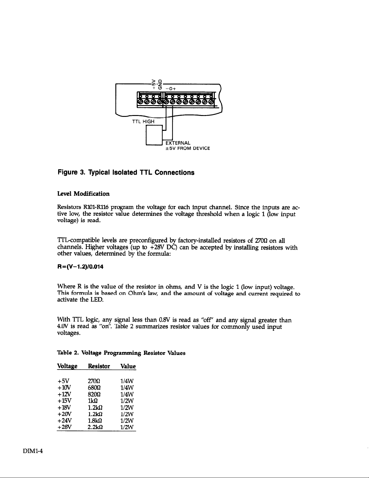
Figure 3. Typical Isolated TTL Connections
Level Modification
Resistors RX&R116 pr’ogram the voltage for each input channel. Since the inputs are active low, the resistor value determines the voltage threshold when a logic 1 (low input
voltage) is read.
TTLcompatible levels are preconfigured by factory-installed resistors of 27062 on all
channels. Higher voltages (up to +28V DC) can be accepted by installing resistors with
other values, determined by the formula:
R=(V-1.2)/0.014
DIMl-4
Where R is the vaIue of the resistor in ohms, and V is the logic
This formula is based on Ohm’s law, and the amount of voltage
activate the LED.
With TTL logic, any signal less than OBV is read as “ofp and any signal greater than
4.OV is read as “on’! Table 2 summarizes resistor values for commonly used input
voltages.
1 (low input) voltage.
and current required to
Table 2. Voltage Programming Resistor Values
Voltage Resistor
+SV
+lOV
+w
+lsv
+lBV
+2Ov
+24v
+2tw
27OQ
68062
8200
lk61
1.2kil
1.2m
l.Bk!J
2.2kQ
Value
114w
ll4W
ll4W
ll2W
ll2W
ll2W
ll2W
ll2W
Page 5

Commands
DIM1 module commands are listed in Table 3. Table 4 summarizes the locations for slotdependent commands.
Table 3. Commands Used with the DIM1 Module
Command Location
DIGITAL A Slot-dependent CMDA
DIGITAL B Slot-dependent CMDB
Table 4. Locations for Slot-Dependent Commands
Slot CMDA CMDB
Slot 1
Slot 2
Slot 3
Slot 4
Slot 5
Slot 6
Slot 7
Slot 8
Slot 9
Slot 10
CFFSO
CFF82
CFF84
CFF86
CFF88
CFF8A
CFFBC
CFWE
CFF90
CFF92
CFF81
CFF83
CFF85
CFF87
CFF89
CFDSB
CFWD
CFFSF
CFF91
CFF93
DIGITAL A
Location: Slot-dependent CMDA
The command DIGITAL A is used to read port A (channels O-7) on the DIMl. This
command and location is always read, never written to. When read, DIGITAL A returns
an g-bit binary number, bits O-7 representing the status of channels O-7 respectively. See
Table 5.
If it is necessary to know the status of a single channel, a logical AND statement can
be used in assembly language to mask out the irrelevant bit positions and irrelevant
bits. The mask should contain O’s in all irrelevant bit positions and a 1 in the bit position that represents the status of the channel in question. The result will be an 8 bit
binary number where each bit is 0 except the one bit that indicates the status of the
channel being read.
When reading the DIM1 module from BASIC, it will be necessary to convert the
decimal value returned by a PEEK statement into its binary equivalent. The 8 bits of
this binary number will reflect the status of a single channel.
The grouping of digital inputs into ports allows data from up to eight channels to be
read simultaneously.
DIMl-5
Page 6

Note that the DIM1 module inverts incoming data. If a channel input is high, the
respective bit position will be set to 0.
Table 5. Bit Configuration for DIGITAL A
lY7 D6 D5 D4 D3 D2 Dl DO
Cl-V
Ch6
DIGITAL B
Location: Slot-dependent CMDB
DIGITAL B is the equivalent of DIGITAL A, operating in exactly the same manner, but
addressing Port B of the DIM1 (channels 8-15. See Table 6 for configuration.
Table 6. Bit Configuration for DIGITAL B
w
Chl5 Ch14 Ch13 Chl2
D6 D5 D4 D3 D2 Dl DO
Theory of Operation
For the following discussion, refer to schematic drawing number 500-236.
Optical isolators UlOl-R116 (TIL117) are the primary components of the Digital lnput
Module, providing isolated digital sensing for input channels O-15. Each isolator contains
an internal transmitting LED (driven by the input signal) and a receiving photo transistor, which is connected to the output pin of the IC. Pull ups for these outputs are
provided by Rll7 and RllB.
Ch5
Ch4 Ch3
Chll ChlO Ch9 Ch8
Ch2 Chl ChO
DIM%6
The threshold sensitivity of isolators UlOl-U116 is determined by the values of voltage
programming resistors RlOl-R116, respectively. The DIM1 module is shipped from the
factory with 2703 resistors installed. In this configuration, the DIM1 module will accept
standard TTLlevel signals. The + terminals of the input channels are connected
together by WlOl and W102.
The outputs of UlOl-U116 drive buffers U117 and Ull8, two octal inverter, buffers
(74LS240). The outputs of U117 and U118 are connected to the data lines (DO-D7 and
FO-F7) of the system data bus. port A of the DlMl module (channels O-7) is directed
through U117, and port B (channels g-15) directed through Ull8. Enabling of U117 is triggered by command line CMDA, and U118 by command line CMDB.
Page 7

DIM1 Specifications
Input channels: 16
Input characteristics: TTL compatible, low true Logic 1 drive = 14mA sink at <0.5V
Isolation:
Technique: optical
Channel to ground: 500V peak max
Channel to channel: 0 (jumper plugs installed)
User configurable characteristics:
Input voltage: up to 28V max
Channel to channel isolation: 500V peak (jumper plugs removed)
External supply requirements (for channel to channel isolation): 5 to 28 volts at 14mA
per channel
DIMl-7
Page 8

MOAVl lN3NOdHl03 LIMI
8-w1a
Page 9

‘- 1 I
I -1
DIM1 SCHEMATIC DIAGRAMS
DIME9/DIMl-10
 Loading...