

Page 1

titlepg.frm Black 1
DAS-1600 External Driver
User’s Guide
Revision C - October 1993
Part Number: 58074
Page 2

noticep.frm Black 2
The information contained in this manual is believed to be accurate and reliable. However, Keithley
Instruments, Inc., assumes no responsibility for its use; nor for any infringements or patents or other
rights of third parties that may result from its use. No license is granted by implication or otherwise
under any patent rights of Keithley Instruments, Inc.
KEITHLEY INSTRUMENTS, INC., SHALL NOT BE LIABLE FOR ANY SPECIAL, INCIDENTAL,
OR CONSEQUENTIAL DAMAGES RELATED TO THE USE OF THIS PRODUCT. THIS
PRODUCT IS NOT DESIGNED WITH COMPONENTS OF A LEVEL OF RELIABILITY THAT IS
SUITED FOR USE IN LIFE SUPPORT OR CRITICAL APPLICATIONS.
Refer to your Keithley Instruments liccnsc agreement and Conditions of Sale document for specific
warranty and liability infommtion.
VIBWDAC, EASYBST LX, and ASYST are registered trademarks of Keithley Instruments, Inc.
EASYEST AG is a trademark of Keithley Instruments, Inc. All other brand and product names we
trademarks or registered trademarks of their respective companies.
0 Copyright Keithley Instruments, Inc., 1993.
All rights reserved. Reproduction or adaptation of any part of this documentation beyond that permitted
by Section 117 of the 1976 United States Copyright Act without permission of the Copyright owner is
unlawful.
Keithley Instruments, Data Acquisition Division
440 Myles Standish Blvd.
Taunton,
MA 02780
Telephone: (508) 8X0-3000. FAX: (508) 880-0179
Page 3

1600ext.toc Black iii
+B
Table of Contents
Preface
Using the DAS-1600 Extertial Driver
Supported Hardware
Options Supported,
Files on Disk
QuickStart
Setting Up the Board.
Running the Configuration Program.
Loading the DAS-1600 External Driver.
Accessing the DAS-1600 External Driver
VlEWDAC
EASYEST LX/AG
ASYST
Using the Configuration Program
MenuItelns
Exiting the DAS- 1600 Configuration Program
Loading the External Driver in Multiple Board Configurations
DAS-1600 External Driver Characteristics
Channels and Gains.
EXP-16s and EXP-GPs.
Cascading Multiple EXP Boards.
Specifying Gains
Digital I/O,
DAS-1600/1200 Series
DAS-1400 Series
Internal Clocking.
External Clocking.
Synchronous, DMA, and Interrupt Operations,
Counter/Timer Functions
EventCounting
Pulse Output.
.........................................
.........................................
.......................................
...................................
....................................
................................
.................... .3
....................................
...............................
......................... .6
......................................
................. .12
................................
.............................
...................
.................................
.......................................
...........................
................................
..................................
.................................
............................
...............................
...................................
...3
................. .4
................ .5
...5
...6
...7
........... .ll
........... .19
...2 1
.l
.l
.2
.3
.5
.l 1
.12
.13
.I3
.14
.15
.15
.1X
.19
.I9
.20
.21
iii
Page 4

1600ext.toc Black iv
fb
4
Pseudo-Digital Output: Extended Functions.
Analog Triggers ...........................
Burst Mode and SSH Mode.
Altering the Burst Mode Conversion Rate.
Software Interrupt Vectors .....................
DAS-1600 External Driver Error Messages
List of Figures
Figure 1.
Figure 2.
List of Tables
Table 1.
Table 2.
Table 3.
Table 4.
Table 5.
Table 6.
Table I.
Table 8.
Table 9.
Table 10.
Table 11.
Table 12.
Table 13.
Table 14.
Table 15.
Table 16.
Analog Trigger Conditions
Using a Hysteresjs Value.
Configuration Program Menu Items
Configuration Menu Special Keys
Supported Gains and Gain Codes
Logical and Physical Channels
Digital I/O Channel Usage (No EXPs,
All Ports Output).
Digital I/O Channel Usage (EXPs Used,
All Ports Output).
Digital I/O Channel Usage (No EXPs,
A and B Output, CL and CH Input).
Digital I/O Channel Usage (No EXPs,
B and CH Output, A
Digital I/O Channel Usage (No EXPs)
Digital I/O Channel Usage (EXPs Used)
Counter/Timer Functions.
Pseudo-Digital Output Channels.
Default Settling Times.
Common Settling Times
Interrupt Vectors ..........................
Error Messages
.................
........................
........................
and
CL Input).
..................
....................
...................
..........................
.......
......
..........
..........
...........
............
..............
..........
..........
............
........
......
.21
.25
.21
.29
.31
.32
.26
.21
I
.I0
.12
.14
.16
.17
.17
.1x
.18
.19
.20
.22
.29
.30
.31
.32
4
iv
Page 5

preface.frm Black v
Preface
The
DAS-1600 External Driver
you need to use the DAS-1600 External Driver (somtimes referred to as
the External DAS Driver). The DAS-1600 External Driver allows you to
use Keithley’s DAS-1600, DAS-1400, and DAS-1200 Series boards with
the following Keithley
. VIBWDAC@
data
User’s Guide provides the information
acquisition and analysis soCtware:
. EASYEST LX@
. EASYEST AG’M
. ASYST@
This manual is intended for application programmers. It should be used in
conjunction with the DAS board user’s guide and with the documenlation
for the data acquisition software you are using.
Note: The DAS-1600 External Driver may support options your software
does not; likewise, your software may suppou options this extemal driver
does not.
4
Page 6

preface.frm Black vi
If you need help, contact your local sales office or Keithley’s Applications
Engineering Department between 8 am and 7 pm (EST), Monday through
Friday:
Keithley Data Acquisition
Applications Engineering
440 Myles Standish Boulevard
Taunton, Massachusetts 02780
Telephone 508/880-3000
Telex 503989
FAX 508/X80-0179
An applications engineer will help diagnose and resolve your problem by
telephone.
4
vi
Page 7

chapOO_.frm Black 1
Supported Hardware
4+
Using the DAS-1600
External Driver
The DAS-1600 External Driver allows your VIEWDAC, EASYEST LX,
EASYEST AG, or ASYST application program to exchange data with
DAS-1600, DAS-1400, and DAS-1200 Series boards.
The DAS-1600 External Driver supports the following Keithley data
acquisition (DAS) boards.
. DAS-1601
. DAS-1602
. DAS-1401
. DAS-1402
.
DAS- 1201
. DAS-1202
Options Supported
The DAS-1600 External Driver supports the following options:
. Analog input operations, including interrupt and Direct Memory
Access (DMA)
-
16 single-ended or eight differential 12-bit analog input channels
1
Page 8

chapOO_.frm Black 2
Files on Disk
-
Up to 136 channels through EXP-16 and EXP-GP support
Two 12-bit analog output channels (on the DAS-1601 and DAS-1602
.
only)
32 digital I/O bits on the DAS-1601, DAS-1602, DAS-1201, and
.
DAS-1202; eight digital I/O bits on the DAS-1401 and DAS-1402
. Event counting
. Pulse output
. Analog triggering
. Simultaneous sample-and-hold through the SSH4A
The following files arc included on the DAS-1600 External Driver disk:
DAS1600.EXE -This file is the external DAS driver for DAS-1600,
DAS-1400, and DAS-1200 Series boards. It controls the boards and
allows communication between an application program and the
board. DAS1600,EXE executes as a terminate-and-stay-resident
(TSR) program that occupies a small amount of memory in the host.
D1600CFG.EXE -This is the configuration program for the
DAS-1600, DAS-1400, and DAS-1200 Series boards. It creates
configuration files that the DAS-1600 External Driver
(DAS1600,EXE) can read.
DAS1600.CFG - This is the default configuration file used by
DAS1600,EXE when no file name is specified. When first used, this
file contains the default configuration settings for DAS-1600 Series
boards.
DAS1400.CFG - When iirst used, this file contains the default
configuration settings for DAS-1400 Series boards.
DAS1200.CFG - When first used, this file contains the. default
configuration settings for DAS-1200 Series boards.
Using the DAS-1600 External Driver
Page 9

chapOO_.frm Black 3
Quick Start
Setting Up the Board
This section describes how to configure, install, and access the DAS-1600
External Driver.
Referring to the appropriate DAS user’s guide, set the switches on the
board to select the board’s base address, input configuration (single-ended
or differential), analog-to-digital (A/D) and digital-to-analog (D/A) range
type (unipalar or bipolar), D/A reference voltages, DMA channel, clock
rate select, wait state enable, and A/D gain. Remember these settings; you
will need them when you run the configuration program,
D1600CFG.EXE, described in the next section.
The following are a few DAS-1600/1400/1200 Series connections that
you may want to keep in mind:
External digital trigger Connect the external digital trigger signal
.
to the IPl pin on the main I/O connector.
External clock Connect the external clock signal to the IPO pin on
.
the main I/O connector.
. Event counting - Connect the event signal Lo the CTR 0 IN pin on the
main I/O connector.
. Pulse output Connect the pulse output signal to the CTR 2 OUT pin
on the main I/O connector.
Refer to your DAS board user’s guide for other connections.
Running the Configuration Program
The DAS-1600 External Driver is shipped with default configuration files
that reflect the factory settings of DA.%1600/1400/1200 Series boards.
Whenever you change any of these settings, you must run the DAS-1600
configuration program, D1600CFG,EXE, in order for the external driver
to hmction properly.
3
Page 10

chapOO_.frm Black 4
When you load the external driver, as described in the following section,
the external driver looks in the current directory for the default
confIguration file, DASl600.CFG. You can also specify the name of an
existing configuration file, such as DAS 14OO.CFG for a DAS-1400 Series
board or DAS1200,CFG for a DAS-1200 Series board, or the name of a
new configuration file that you want to define.
To run the menu-driven configuration program, perform the following
steps:
1. Create a DAS 1600 directory on your hard disk. For example, at the
DOS prompt, enter the following:
mkdir das1600
2. Copy the following files from the DAS-1600 External Driver disk to
the DAS1600 directory: DASl600EXE, Dl600CFC.EXE,
DASl600.CFG, DASl400,CFG, and DASl200,CFG.
3. Enter the following at the DOS prompt:
cd \das1600
D1600CFG corlfiguration_filename
where
cnnfigurationfilenume represents the DOS path and name of
your configuration file. For example, you could name the
configuration file DAS 1602.CFG and specify the path as
c:Was1600Llas1602.cfgg. If you do not specify a co&oration file, the
current directory and the default filename, DASl600.CFG, are used.
4. Configure the board parameters using the configuration program, as
described in “Using the Configuration Program” on page 6.
Loading the DAS-1600 External Driver
You must load the DAS-1600 External Driver, DASl600.EXE, each time
you start up your computer in order for your application program to
recognize it. The DAS-1600 External Driver remains in memory until you
turn off or reboot your computer.
Using the DAS-1600 External Driver
Page 11

chapOO_.frm Black 5
To load the DAS-1600 External Driver, access the directory containing
DAS1600,EXE and enter the following at the DOS prompt:
das1600
configuration_filename
where configurationfilcnamc is the name of the configuration file you
are using. If you do not specify a configuration file, the driver searches for
the default configuration file, DAS1600,CFG. in the current directory.
Note:
You can also load the DAS-1600 External Driver automatically
whenever you start the computer by modifying your AUTOEXEC.BAT
file.
Accessing the DAS-1600 External Driver
This section describes how to access the DAS-1600 External Driver when
using VIEWDAC, EASYEST LX, EASYEST AG, and ASYST. For
additional information, refer to your VIEWDAC, EASYEST LX / AG, or
ASYST documentation.
VlEWDAC
If the DAS-1600 External Driver is the only driver installed in your
system, your VIEWDAC application programs access the DAS-1600
External Driver automatically. If more than one driver is installed, you
must select the external driver (board name) from within a VIEWDAC
DAS Task.
EASYEST LX/AC
If the DAS-1600 External Driver is the only driver installed in your
system, your EASYEST LX / AG application programs access the
DAS-1600 External Driver automatically.
5
Page 12

chapOO_.frm Black 6
If more than one driver is installed, you must perform the following steps
to access the DAS-1600 External Driver:
1. Select Devices from the EASYEST LX / AG menu bar
I
-
ASYST
2. From the
Selecrion.
3. Select the appropriate external driver (board name) from the
displayed list.
If you are using ASYST, always perform the following steps to access the
DAS-1600 External Driver:
1. After loading the DAS-1600 External Driver, start up ASYST version
2.10 or greater and permanently load
DAS
menu. ASYST automatically searches for and creates a DAS device
called DAS1600.
2. Enter the following at the OK prompt to make DAS-1600 the current
device:
DAS Configuration
Driver Support system overlays from the Data Acquisition
DAS1600
screen, select option 1,
the Data Acq
Master and the Ext
DAS Board
Using the Configuration Program
The configuration program begins by prompting you to specify the
number of DAS-1600/1400/1200 Series boards you want to configure.
You can configure up to two boards in each configuration file. The
program then displays the configuration menus. The menu options are
described in the following subsection.
6
Using the DAS-1600 External Driver
Page 13

chapOO_.frm Black 7
Menu Items
Menu Item
Board Type’
Clock Rate Select’
AID Input Mode’
The D1600CFG.EXE
configuration program menu items are described in
Table I
Table 1. Configuration Program Menu Items
Choices
DAS-1601
DAS-1602
DAS-1401
DAS-1402
DAS-1201
DAS-1202
1 MHz or 10 MHz
Bipolar or Unipolw
Default Value
DAS-1601
10 MHz
Bipolar
D/A Channel O/l
Output Mode’
This option is available only on the
DAS-1601/1602 and DAS-1401/1402.
Bipolar or Unipolar
This option is available only on the
DAS-1601/1602.
I
Bipolar
Page 14

chapOO_.frm Black 8
+b
Table 1. Configuration Program Menu Items (cont.)
Menu Item
DMA Channel’ 1
Digital I/O
Configuration
Choices Default Value
If you are using more than one board in your
system, the DMA channel must be different for
each board.
Input or Output (for each of the four
configurable ports)
This option is available only on the
DAS-1601/1602 and the DAS-1201/1202.
or3
3
Output (for all ports)
Set EXP-16 Gains’
0.5 through 200C (for each EXP-16)
This option is available only if an EXP-16 is
present. Selecting this item switches control to
the EXP-16 gain window, which allows you to
select the gain of each EXP-16 channel. Press
[Esc] to return to the main menu when all gains
are set.
Using the DAS-1600 External Driver
1 (for all EXP-16s)
Page 15

chapOO_.frm Black 9
Table 1. Configuration Program Menu Items (cont.)
lenu Item Choices
IXP-GP Gains’
/ 1 or 2.5 (for each EXP-GP)
1, 10, 100, or 1000 (for each EXP-GP channel
if a gain of 1 is selected)
2.5,25,250, or 2500 (For each EXP-GP
channel if a gain of 2.5 is selected)
This option is available only if an EXP-GP is
present. Selecting this item displays all
EXP-GP boards that ate present. Select a
board: then select its global gain. Then select a
EXP-GP channel, and the channel’s gain. Press
@SC] to retuo to the previous menu and then to
the main menu.
Default Value
1 (for all EXP-GP
boards and channels)
slumber of
jSH-4As’
0 through 4
The maximum number of SSH-4As allowed
deoends on the number of EXP-16s and
EXP-GPs present.
0
9
Page 16

chapOO_.frm Black 10
Table 1. Configuration Program Menu Items (cont.)
Menu Item
SSH-4A Mode’ Master or Slave Master
A/D Gain’ I, 2.4, or 8 (for DAS-1202) 1
/ Choices Default Value
This
option
is only available if an SSH4A is
present. It should match the mode switch of the
first SSH-4A.
1, 10, 100, or 500 (for DAS-1201)
This
option is
and DAS-1202.
available only on the DAS-1201
Notes
’ This setting is
hardware
You
can use the keys listed in
dependent: it must
match the
Table 2 for
lwdware
(board) setting.
special purposes within the
configuration menus.
I
10
Table 2. Configuration Menu Special Keys
Special Keys Description
[ESCI
Exit the configuration program with the option of saving the
current settings to a file.
Display a diagram of the DAS-1600/1400/1200 Series
hxdware switch settings that match the current driver
configuration, followed by (if EXPs or SSH-4As are
configured) an EXP and SSH-4A logical-to-physical-channel
mapping table.
Using the DAS-1600 External Driver
Page 17

chapOO_.frm Black 11
Exiting the DAS-1600 Configuration Program
To exit the D1600CFG.EXE configuration program, press [Esc].The
configuration file displays the following prompt:
Update
where
file.
Enter [Y] to save the configuration and return to DOS. Enter IN] to exit to
DOS without saving the configuratiod. Enter [Esc] to return to the
configuration program.
configuration_filename? (Yes
exit or [Escl to cancel)
configuration
filename represents the name of your configuration
and exit/No and
Loading the External Driver in Multiple Board
Configurations
The number of DAS-1600/1400/1200 Series boards that you can install in
your system is limited by the available slots in your computer. Each
memory-resident external driver can support two DAS-1600/1400/1200
Series boards. The number of external drivers that you can load is limited
only by the amount of available memory in your computer.
Note: Some operations may not be available when using multiple DAS
boards depending on the system resources that the operations require and
how system resources are allocated. For example, DAS-1600 Series
boards support two DMA channels; therefore, if you are using both DMA
channels on one board, you cannot perform a DMA operation on the
second board.
To access more than two boards, load the DAS-1600 External Driver as
many times as you have configuration files. For example, to access three
boards, you can create two configuration files called D1600-l.CFG and
D1600-2.CFG, where D1600-l.CFG contains the configuration data for
two boards at addresses 300h and 310h and D1600-2.CFG contains the
11
Page 18

chapOO_.frm Black 12
DAS-1600 External Driver Characteristics
Channels and Gains
configuration data for a single board at address 340h. To load the
DAS-1600 External Drivers, use the following syntax:
DAS1600 D1600-l.CFG
DAS1600 D1600-2.CFG
The following sections describe special attributes and operating
characteristics of the DAS-1600 External Driver.
DAS-1600
and
DAS-1400 Series boards support channel-gain queues of
128 channels. Channel-gain queues are not supported by DAS-1200
Series boards. Table 3 lists the gains and corresponding gain codes
supported by DAS-1600/1400/1200 Series boards.
Table 3. Supported Gains and Gain Codes
Board Gain Gain Code
DAS-1601 I1
Notes
’ Gains on DAS-1200
IO
Series boards are not
software programmable. They are
displayed here for use in altering the burst
mode conversion
rate only.
12
Using the DA%1600 External Driver
Page 19

chapOO_.frm Black 13
EXP-16s and EXP-GPs
You can use the following expansion boards with DAS-1600/1400/1200
Series boards:
. EXP-16 -Each EXP-16 board multiplexes 16 differential inputs into
one output signal. Use Output Channel jumper 54 on the EXP-16 to
assign the output signal to one of the analog input channels on the
DAS-1600/1400/1200 Series board.
If you are using more than one EXP-16, you must assign each
EXP-16 to a different analog input channel on the
DAS-1600/1400/1200 Series board. Assign input channel 0 to the
first EXP-16, channel 1 to the second EXP-16, and so on.
. EXP-GP Each EXP-GP board multiplexes eight inputs into one
output signal. Use Output Channel jumper 54 on the EXP-GP to
assign the output signal to one of the analog input channels on the
DAS-1600/1400/1200 Series board.
If you are using more than one EXF-GP, you must assign each
EXP-GP to a different analog input channel on the
DAS-1600/1400/1200 Series board. Assign input channel 0 to the
fist EXP-GP, channel 1 to the second EXP-GP, and so on.
Note: The DAS-1600/1400/1200 Series board must be set up for
single-ended operation when it is used with a EXP-16 or EXP-GP.
Cascading Multiple EXf Boards
A physical channel is the analog input channel on the
DAS-1600/1400/1200 Series board to which the EXP board is assigned.
The logical channel is the channel that the application software uses to
access channels on the DAS-1600/1400/1200 Series board and any EXP
boards. The logical and physical channel assignments are displayed in the
D1600CFG.EXE configuration program when you select
You can cascade multiple EXI-16 and EXP-GP boards by assigning each
EXP board to a distinct analog input channel on a DA.%1600/1400/1200
Series board as discussed previously. You can also connect an STA-16 to
Show Switches.
13
Page 20

chapOO_.frm Black 14
the system to use the remaining analog input channels on the
DAS-1600/1400/1200 Series board.
Note: If you are using an STA- 16 with EXP boards, the channels used by
the EXP-GPs and EXF-16s are still accessible on the STA-16. However,
make sure that you do not connect any signals to these inputs.
Digital output bits OPO to OP3 are used to select the current channel on
the EXP boards. The DAS-1600 External Driver does not allow you to
use these output bits if any EXP boards are configured.
Table 4 shows the relationship between the logical and physical channels
on aDAS- when using two EXP-GPs and two EXP-16s.
Specifying Gains
VIEWDAC uses the EXP-16 and EXP-GP gains specified in the
configuration tile. For EASYEST LX and AG, you must set the gain of
channel 0 only (channel 0 is on the first EXP-16 or on the first EXPGP if
no EXP-16s are configured); choose
logical-to-physical-channel mapping table). In this case, the gain of all
channels is relative to the setting of the A/D range type (unipolar or
bipolar)
than the gain of chatmel 0 if the gain for other channels differs.
Table 4. Logical and Physical Channels
Logical Channels Physical Channel EXP-GP’ EXP-16
I oto 15
32 to 39
~~~~~~~~~~ ~~~~~~~~~ ~~~~~~~
48 to 59
and the
gain of channel 0. You must compensate for gains other
I Em-16: 0
..: ,..,..j....,.l .../.... ~,~ .,./.,. .j.,........,..j....j ~...~ ,..,........, ,,../..,./
EXP-GP: 2 2
DAS-1602: 4 to 15 Not
Show Switches
Jumper J4
IO I
applicable
to display the EXF
14
Using the DAS-1600 External Driver
Page 21

chapOO_.frm Black 15
Note:
range is fl2 V, not f20 V.
When using a gain of 0.5 on the EXI-16, the maximum input
Digital I/O
Since the extended digital ports (32 to 46) require 12 output bits, the
software always shows a minimum of 12 available bits, no matter how a
digital output port is configured. If a digital output port is configured for
X,4, or 0 output bits, you can disregard the extra bits. The following
subsections describe the digital I/O support on the various DAS boards.
DAS- 1600/1200 Series
The DAS-1600/1200 Series boards have four fixed digital input bits and
four fixed digital output bits. In addition, an Intel 8255 integrated circuit
is included on the board to provide 24 additional digital bits. These 24 bits
are organized into four ports (ports A, B, CL, and CH): you can configure
each port for either input or output.
Note:
bits are dedicated to EXP board control and are not available for digital
outuut.
When an EXP board is configured, the four fixed digital output
The DAS-1600 External Driver supports one digital input channel and
one digital output channel on each board (if any bits are available). The
number of bits used in each channel depends on the port configuration
and whether an EXP board is configured.
Starting from the least significant bit;Port A uses the first eight bits
available, Port B uses the next eight bits available, Port CL uses the next
four bits available, Port CH uses the next four bits available,
bits use the next four bits available. If a particular port is configured for
input, it does not use any bits in the output channel; if a particular port is
configured for output, it does not use any bits in the input channel.
and
the fixed
15
Page 22

chapOO_.frm Black 16
Note:
The digital channel requires DP.INTEGER output if more than 16
bits are configured.
For example, a DAS-1600/1200 Series board is configured with no EXPs
and with Port A, Port B, Port CL, and Port CH all configured for output.
Table 5 illustrates how the bits in the digital I/O channels are used.
Table 5. Digital l/O Channel Usage
(No EXPs, All Ports Output)
Bits Output Channel Use Input Channel Use
0 to 3
l4to7
/ 8
to 11 / Port B
I
Port A
4 fixed input bits
/12to15 I
1
16 to 19
/Port CL
120~~23 jPortCH
I24 to 27 / 4 fixed output
16
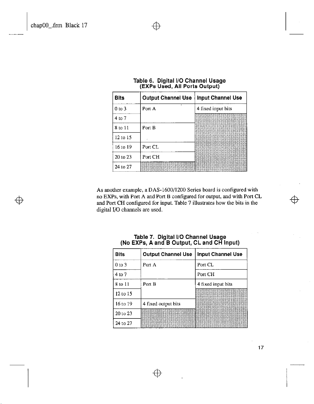
As another example, a DAS-1600/1200 Series board is configured with
one or more EXPs and with Port A, Port B, Port CL, and Port CH
configured for output. Table 6 illustrates how the bits in the digital I/O
channels are used. Note that the four fixed output bits are dedicated to
EXP board control and are not available.
Using the DAS-I600 External Driver
Page 23
chapOO_.frm Black 17
Table 6. Digital l/O Channel Usage
(EXPs Used, All Ports Output)
Bits Output Channel Use
1 /PortCH
20 to 23
Input Channel Use
As another example, a DAS-1600/1200 Series board is configured with
no EXPs, with Port A and Port B configured for output, and with Port CL
and Port CH configured for input. Table 7 illustrates how the bits in the
digital I/O channels are used.
Table 7. Digital I/O Channel Usage
(No EXPs, A and B Output, CL and CH Input)
Bits
Output
Port A
Channel Use
Istoll /PortB
12 to
15
16 to 19 4 fixed output bits
to
20
23 ~
27
.: ..I .,..,..... ..I
24 to
Input Channel Use
1 4 fixed inout bits
“~“““~,““‘i’.i.i’.‘.‘.‘.‘.~.‘i.‘~’-
17
Page 24

chapOO_.frm Black 18
As a final example, aDAS-1600/1200 Series board is configured with no
EXPs, with Port B and Port CH configured for output, and with Port A
and Port CL configured for input. Table 8 illustrates how the bits in the
digital I/O channels are used.
Table 8. Digital I/O Channel Usage
(No EXPs, B and CH Output, A and CL Input)
DAS-1400 Series
DAS-1400 Series boards have four fixed digital input bits and four fixed
digital output bits.
Note:
bits are dedicated to EXP board control and are not available for digital
output.
Table 9 illustrates how the bits in the digital I/O channels are used if a
DAS-1400 Series board is configured with no EXPs.
16
When an EXP board is configured, the four fixed digital output
Table 9. Digital l/O Channel Usage (No EXPs)
1 sits Output Channel Use Input Channel Use
/ 0 to 3 / 4 fixed output bits
1 4 fixed input bits
Using the DAS-1600 External Driver
Page 25

chapOO_.frm Black 19
Table 10 illustrates how the bits in the digital I/O channels are used if a
DAS-1400 Series board is configured with one or more EXPs. Note that
the four fixed output bits are dedicated to EXP board control and are not
available.
Table 10. Digital l/O Channel Usage (EXPs Used)
Bits
0 to 3
Output Channel Use
i~~~~:~~,~~,~:~~~,~~ 4
Input Channel Use
fixed input bits
Internal Clocking
When using an internal clock source, a conversion begins without waiting
for an external clock signal and proceeds at the specified rate until
finished. With the jumper in the 1 MHz position, the clock resolution is
1 ps. With the jumper in the 10 MHz position, the clock resolution is
0.1 NS.
External Clocking
When using an external clock source, the software waits for a rising edge
at the lP 0 input pin before starting each conversion. Acquisition proceeds
and is paced by the external clock until the requested amount of data is
acquired.
Synchronous, DMA, and Interrupt Operations
Keep the following in mind when performing a synchronous, DMA, or
interrupt operation:
l
Only one operation can be active on a board at one time.
. Burst mode and continuous acquisition are not supported for
synchronous operations.
19
Page 26

chapOO_.frm Black 20
4
l
DMA mode is allowed only for analog input operations. DMA
supports burst mode acquisition. The use of channel-gain queues is
not allowed for DMA mode. DMA cannot be performed on EXP-16 /
EXP-GP channels. Only non-cyclic (single cycle) and cyclic
(continuous) single buffering are supported for DMA operations;
double buffering is not supported.
4
. Interrupt mode is supported for analog input, analog output,
digital I/O operations, Burst mode is not supported for interrupt
operations. Only non-cyclic (single cycle) and cyclic (continuous)
single buffering are supported for interrupt operations; double
buffering is not supported.
Note:
interrupt overmn conditions, ensure that interrupt operation speeds
are valid for your system.
Because the DAS-1600 External Driver cannot detect all
Counter/Timer Functions
Table 11 shows the counter/timer functions supported by the DAS-1600
External Driver. The supported functions are described in the following
subsections.
Table 11. Counter/Timer Functions
Function
Timer Interrupt NO
GHV3WiOll
Supported
and
4
I
I
20
Using the DAS-1600 External Driver
4
Page 27

chapOO_.frm Black 21
Event Counting
Pulse Output
Pseudo-Digital Output: Extended Functions
4
To perform event counting, comlect the signal to be counted to CTR 0 IN.
The maximum count is 65,535; any count greater than 65,535 causes
driver error 32791, “Event counter overflow.” Note that if the signal being
counted starts high, with events driving it temporarily low, each event is
counted correctly. However, if the signal being counted starts low, with
events driving it temporarily high, the first event is skipped and
subsequent counts return one less than the actual number of events.
A pulse output generates a pulse train on CTR 2 OUT. The duty cycle of
the pulse tram is fixed at 50% due to the nature of the 8254 counter/timer
circuitry.
DAS-1600/1400/1200 Series boards provide some features that are not
standard features of Keithley software. To access these additional
features, the DAS-1600 External Driver uses pseudo-digital output
channels. Pseudo-digital output channels are digital output channels
supported by Keithley software; these channels are used by
DAS-1600/1400/1200 Series boards for control only, not for output.
(DAS-1600/1400/1200 Series boards support digital output channel 0 for
output operations.)
Note:
output lines on the board. Values written to the pseudo-digital output
channels are intercepted by the DAS-1600 External Driver and are used to
set up the non-standard features.
Table 12 lists the pseudo-digital channels available in the DAS-1600
External Driver and the functions they perform.
Only values written to digital output channel 0 affect the digital
4
21
Page 28

Page 29

chapOO_.frm Black 23
Digital
output
Channel
Function
+b
Table 12. Pseudo-Digital Output Channels (cont.)
Description
38
Analog voltage level The voltage level at which an analog trigger event occurs.
The value written to tbis channel is a raw count value
between 0 and 4095. The voltage equivalent of the raw count
value depends on the input range type (unipolar or bipolar).
For example, a level of 0 is interpreted as 0 V if the analog
input r,ange is 0 to IO V, but it is interpreted as -5 V if the
analog input range is f5 V.
Refer to page 25 for more illformation about analog triggers.
23
Page 30

chap00-.frm Black 24
Digital
Outllut
Table 12. Pseudo-Digital Output Channels (cont.)
Function
Description
4
i\cquisition mode
Set burst mode
-onversion rate for
gain code 0
SSH mode or normal mode. The value written to this channel
can be one of the following:
0 = normal mode
1 = SSH
mode. Refer to page 27 for more information about SSH
mode.
Using a count value, alters the burst mode conversion rate
associated with a gain code of 0. The value written to this
channel depends on a number of factors. Refer to page 29 for
more information.
mode. An SSH4A must be connected to select SSH
24
Set burst mode
conversion rate for
gain code 2
Using a count value, alters the burst mode conversion rate
associated with a gain code of 2. The value written to this
chumcl depends on a number of factors. Refer to page 29 for
more information.
Using the DAS-1600 External Driver
4
Page 31

chapOO_.frm Black 25
Analog Triggers
4
4
Note:
trigger to the DAS-1600 External Driver. If no trigger is found, the
computer will appear to be hung as the DAS-1600 External Driver waits
indefiiitelv for the trigger.
An analog trigger event occurs when one of the following conditions is
met by the analog input signal on a specified analog trigger channel:
. The analog input signal rises above a specified voltage level (positive,
. The analog input signal falls below a specified voltage level
. The analog input signal is above a specified voltage level (positive,
. The analog input signal is below a specified voltage level (negative,
You specify the voltage level as a raw count value between 0 and 4095.
When using analog triggering, make sure that you provide a valid
edge-sensitive trigger).
(negative, edge-sensitive trigger).
level-sensitive trigger).
level-sensitive trigger).
Figure 1 illustrates these analog trigger conditions, where the specified
voltage level is +5 V.
4
25
Page 32

chapOO_.frm Black 26
Figure 1. Analog Trigger Conditions
You can specify a hysteresis value to prevent noise from triggering an
operation. For positive triggering, the analog signal must fall below the
specified voltage level by at least the amount of the hysteresis value
before the trigger event can occur; for negative triggering, the analog
signal must rise above the specilied voltage level by at least the amount of
the hysteresis value before the trigger,event can occur.
The hysteresis value is an absolute number, which you specify as a raw
count value between 0 and 4095.
In Figure 2, the specified voltage level is +5 V and the hysteresis value is
0.1 V. The analog signal must fall below +4.9 V and then rise above +5 V
before a positive trigger event occurs; the analog signal must rise above
+5.1 V and then fall below +5 V before a negative trigger event occurs.
26
4
Using
the
DAS-1600 External Driver
Page 33

chapOO_.frm Black 27
4
+s., v
Level +s !J
/----Is sta,ted
Analog Input
Figure 2. Using a Hysteresis Value
Burst Mode and SSH Mode
Burst mode is a software simulated simultaneous sample-and-hold feature
in which successive analog input channels are sampled as quickly as
possible. Burst mode is supported only for DMA operations. The burst
mode conversion rate defaults to a gain-dependent value that you can
alter. Refer to page 29 for information on altering the burst mode
conversion rate.
SSH (simultaneous sample-and-hold) mode is a hardware feature that
requires use of an SSH-4A. The requested channels are sampled nearly
instantaneously and held until read. The rate between scans is set by the
sample frequency.
*“en, OCC”18
operatlon
Hysteresis e 0.1 V
I-
L
\
.., .., ..,
4
27
Page 34

chapOO_.frm Black 28
4
Note:
not skewed.
When using VIEWDAC or EASYEST LX / AG, you specify the
sampling frequency as the per channel rate. For example, specifying a
frequency of I kHz when acquiring from two channels in paced (normal)
mode results in an aggregate board rate of 2 kHz. When using burst or
SSH mode, the specified sampling frequency is also a per channel rate.
For example, if you specify a frequency of 1 kHz when acquiring from
two channels in burst or SSH mode, the two channels are sampled nearly
instantaneously and are sampled again after 1 ms (1 kHz).
When using ASYST, you specify the conversion delay rather than the per
channel rate. The conversion delay is the time between conversions,
channels to scan. For example, specifying a conversion delay of 1 ms
when acquiring from one channel equates to a 1 kHz sampling rate.
In burst mode, the data is skewed slightly. In SSH mode, the data is
which translates to a sampling rate that is dependent on the number of
Adding a second channel drops the per channel rate to 500 Hz. When
using burst or SSH mode, the conversion delay is interpreted the same
way even though the time between channels is nearly instantaneous. For
example, to sample two channels at a 1 kHz sampling rate, you would
specify a conversion delay of 0.5 ms for each channel, even though the
time between scans is actually 1 ms. This interpretation allows you to
calculate sampling rates that apply with or without burst or SSH mode.
28
The scan sequence in ASYST is as follows:
Paced (normal) mode:
0
[cd] 1 [cd] 2 [cd] (n-l) [cd] 0 [cd] 1 [cd]
Burst or SSH mode:
0
12 3 (n-l) [cd*n] 0 1 2 3 ,. (n-l) [cd*“] 0 1 2 3
cd = conversion delay specified;
0 = start channel;
n = number of channels
[ ] = actual time delay
Using the DAS-1600 External Driver
Page 35

chapOO_.frm Black 29
Altering the Burst Mode Conversion Rate
When a DAS-1600 Series board operates in Dh4A burst mode, it acquires
data in a burst from the channels specified by the start/stop parameters.
The burst is programmed to run at the maximum possible rate, which is
determined by the gain setting. The higher the gain, the more settling time
is required and the slower the burst mode conversion rate.
In some computers, the built-in memory cache can slow the maximum
burst mode conversion rate because caching takes precedence over DMA
operations and causes data loss. In this event, you can adjust the burst
mode conversion rate (settling time) to slow the acquisition rate Table 13
contains the default settling times for each DAS-1600/1400/1200 Series
board gain and the corresponding count value.
Table 13. Default Settling Times
Board
DAS-1601 1 1 / lOus
1 DAS-1602 1
Gain Settling Time
1
Count
2
4
1ous I 2 I
29
Page 36

chapOO_.frm Black 30
+b
If you wish to use a settling time other than the default, you can specify a
count value to alter the burst mode conversion rate. Use the following
formula to determine the appropriate count value:
Count = Settlinr Time (in us) 2
4
The relationship between the settling time and the burst mode conversion
rate is shown in the following equation:
Settling Time (in ps) =
For reference, Table 14 lists some of the most common settling times,
along with their corresponding burst mode conversion rates and counts.
However, you can use any count value between 2 and 255.
Table 14. Common Settling Times
Settling Time (p) Conversion Rate Count
1 MHz
Burst Mode Conversion Rate
Burst Mode
W-W
30
Using the DAS-1600 External Driver
Page 37
chapOO_.frm Black 3 1
Software Interrupt Vectors
The DAS-1600 External Driver uses two software interrupt vectors for
communicating with the application program. The interrupt vectors used
are two of the user interrupts (interrupts 60h to 6711) set aside by DOS. To
ensure that conflicts with other devices, hardware, or programs do not
exist, you can set each of the interrupt vectors to use an interrupt number
that is different from the default.
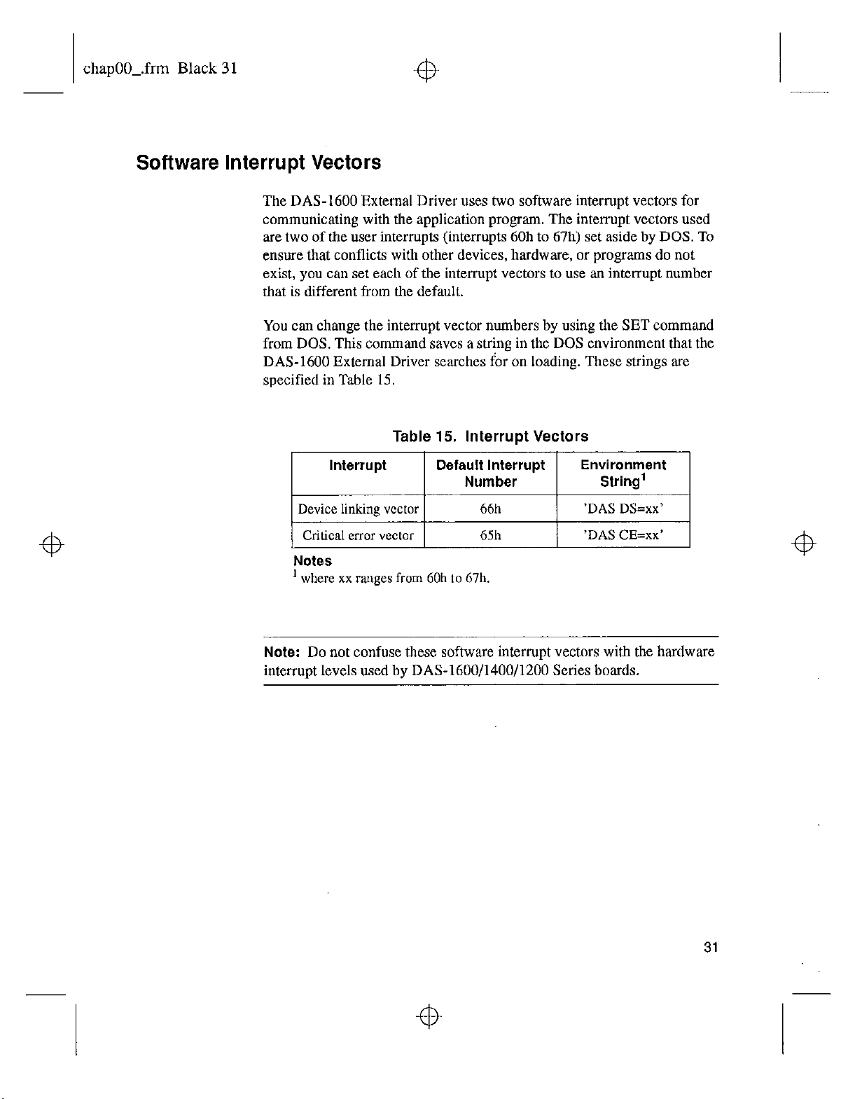
You can change the interrupt vector numbers by using the SET command
from DOS. This command saves a string in the DOS environment that the
DAS-1600 External Driver searches for on loading. These strings are
specified in Table 15.
Table 15. Interrupt Vectors
~~
Notes
’ where xx ranges from 60h to 67h.
Note:
Do not confuse these software interrupt vectors with the hardware
interrupt levels used by DAS-1600/1400/1200 Series boards.
31
Page 38

chapOO_.frm Black 32
DAS-1600 External Driver Error Messaaes
Table 16 lists the error messages that may OCCUT during operation of the
DAS-1600 External Driver.
Table 16. Error Messages
Error
Number
0
~~~~~
28699
28701
28703
28705
~~~~~~~
~: I ~.
32769
Error Message
No error
Resource Busy
Channel Gain Array Not
Supported
Incorrect A/D Uni/Bip
switch setting
Incorrect A/D 1618 Channel The single-ended/ differential switch on the board
switch setting
Function not supported
Description
No errors were encountered.
An attempt was made to execute interrupt and
operations simultaneously. Only one of these
operations is allowed at one time.
A DMA operatjon was attempted with a
channel-gain queue. This is an illegal operation.
The Unipolar/Bipolar switch on the board does not
match the setting that you configured in the driver.
does not match the setting that you configured in the
driver.
A function was requested that is not supported by
the DAS driver.
DMA
I
32
~~~~~
32771
.,.
Non-valid board number A board number that is out of range of configured
boards was requested. This driver can support a
maximum of two boards.
Using the DAS-I600 External Driver
Page 39

chapOO_.frm Black 33
Error Error Message Description
Number
Table 16. Error Messages (cont.)
32773 Board not found at
configured address
32775
D/A not initialized A D/A operation was requested before the D/A
Digital output not initialized
I 32777 I ,
32782 Pulse output period is too
small
The board was not found at the configured address.
The address select switches on the board must
match the settings confirured for the driver.
circuitrv was initialized.
A digital output operation was requested before the
digital output ports were initialized.
‘Ihe pulse period value passed to the driver was too
small.
32785 Conversion delay is too large
32788
I I
Pulse output
large
duty cycle is too
Tbe conversion delay value passed to the driver was
greater than 3 softwax set limit.
The pulse duty +zycle was too large for the number
of period ticks.
33
Page 40

chapOO_.frm Black 34
Table 16. Error Messages (cont.)
Error
Number
32791
32795
Error Message
Event counter overflow
DMA already active
Description
The count exceeded 65535 during an event counting
operation.
A DMA function was called while DMA was being
used by another function. An interrupt function was
called while another
Do not use more than one function that uses the
interrurx channel concurently.
interrupt
function was in use.
34
Using the DAS-1600 External Driver
4
 Loading...