

Page 1
AIM9
LVDT/RVDT Module
This documentation describes the features, installation, and operation of the AIM9
Lm/RVlYI Module in the Series 500 or System 570. This manual also contains important progr amming information and several example programs.
The AIM9 is a dual-channel module for making measurements with AC-driven
transducers such as LvDT’s, RVDT’s, and variable-reluctance transducers. Typically,
linear variable differential transformers (LvDTs) measure linear displacement, while
rotary variable differential transformers (RVDT’s) measure angular displacement.
Throughout this manual, the term “transducer” implies an LVM; RVDT, or other ACdriven, displacement-type sensor.
The AIM93 important features include the following:
Dual channels, each with differential input.
A quick-disconnect terminal block for each channel. Connections include excitation
output, three shield/common terminals, signal A input, and signal B input.
Selectable excitation frequencies of lkHz, 2kHz, 5kHz, lOkHz, or 2OkI-k
Provision for driving the excitation circuitry of up to nine AIM9 modules from the
master oscillator of one AIM9.
Selectable low-pass filter with Wz, 2OHz, and 2OOHz bandwidths. The filter is
software-selectable through the IONAME FILT% parameter.
Continuously variable on-board gain of Xl (*WV full-scale input) to X20 (*0.5V full-
scale input).
Offset adjustments for zeroing the output of the AIM9 gain amplifiers.
Phase adjustment potentiometers to align the excitation and returning signals for
each channel.
Compatibility with Series 500 or System 570. The System 570 accepts one AlM9.
The Series 500 can accept up to nine AIM9 modules.
The AIM9 is intended for transducers which require AC excitation and produce AC output signals. However, it is also compatible with some types of general-purpose DCdriven transducers which normally produce DC output levels. Examples are strain gages
and potentiometric transducers
-
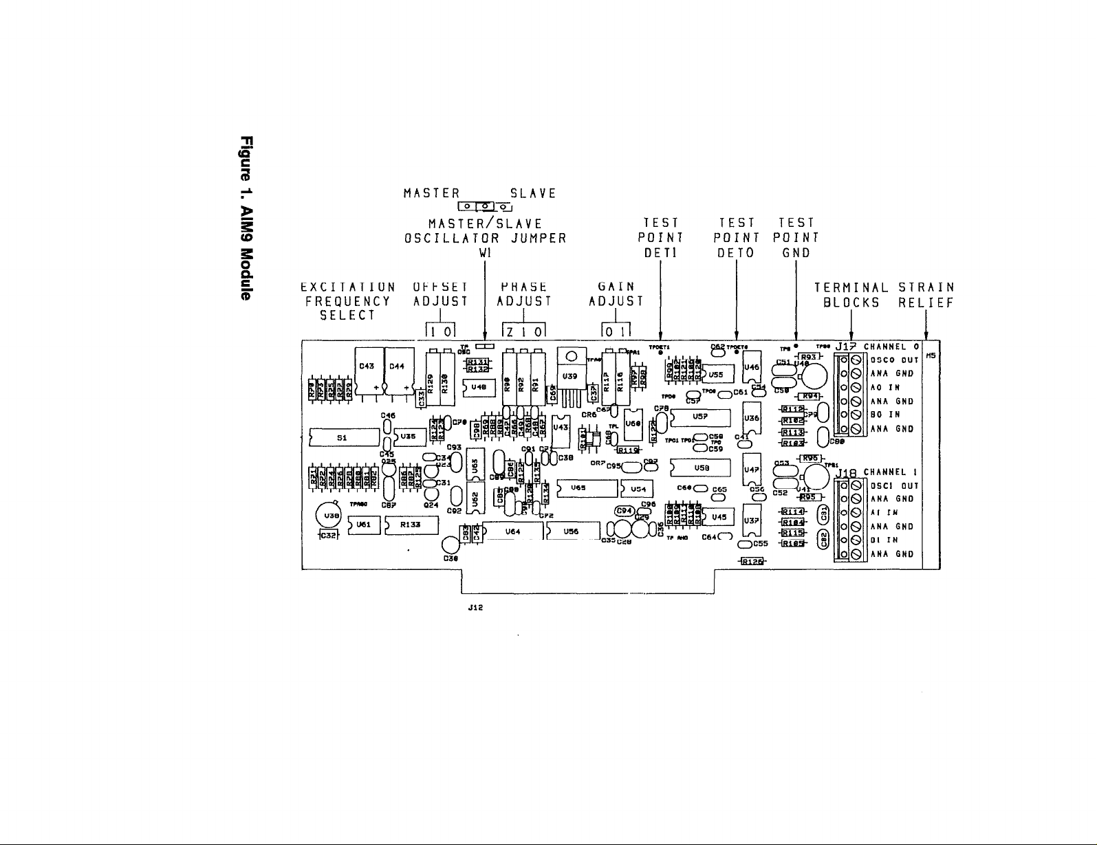
Figure 1 identifies the adjustment potentiometers, jumpers, switches, and important test
points on the AIM9 module.
Document Number: 501-902-01 Rev. B
AIM9-1
Page 2
MASTER
lo(0_lO_I
MASTER/SLAVE
OSCILLATOR JUMPER
SLAVE
Wl
TEST
POINT
DETl
TEST
POINT POINT
DETO
TEST
GND
EXCITATION OFFSET
FREQUENCY
ADJUST
C46
.n.
PHASE
ADJUST
GAIN 1 1 j T;;E.;/;L ;;;fIN
ADJUST
I I I
rm Jl?
CHANNEL (
Page 3
Requirements for Using the AIM9
The AIM9 is hardware-compatiile with Keithky’s IBM-Version Series 500 and System
570 products. When used in the Series 500, the AIM9 requires a master analog input
module AMMl or AIM1 in slot 1. The AIM1 requires either an ADMl or ADM2 A/D
module in slot 2. The System 570 already contains the master analog input and AID
functions, and accepts one AIM9.
The AIM9 is programmed with Soft500 Version 4.0 or later. Soft500 runs under IBM PC
Advanced BASIC (BASICA) included in IBM PC-DOS. IBM PC-DOS versions 3.1 and
later are recommended for use with IBM PC, m, and AT computers.
Compaq computers must run Soft500 under Compaq DOS 3.0 or later, with the matching BASICA version. Earlier versions of Compaq DOS and BASICA are not compati-
ble with Soft500 V4.0 or later.
Soft500 is also compatible with many 100% IBM-compatible computers which run GW-
BASIC under MS-DOS (Version 3.0 or later). Regardless of the brand or rev level of the
DOS, you must use the GWBASIC version which accompanies or is recommended for
the DOS version. Mixing DOS and BASIC versions can cause problems.
The AIM9 module can also be programmed directly using BASIC& PEER and POKE
functions, or the corresponding memory read and write functions of other programming languages. This capability permits the AIM9 to be programmed outside the Soft500
environment.
Installation
Install the AIM9 in any of the slots 2-10 of the Series 500 (slots 3-10 if the AIM1 is used). For maximum immunity to noise, install the AIM9 and any other analog input
modules in the lowest-numbered available slots. The System 570 can accept one AIM9
module in its option slot. For either system, update the configuration table to show the
location of the AIM9.
User-Configured Features
The AIM9 module requires a number of settings and adjustments for best performance
with a given transducer. The user-definable parameters and adjustments include frequency selection, phase correction, zero offset adjustment, and gain adjustment. A
bank of DIP switches sets the excitation frequency. Potentiometers control the phase,
offset, and gain adjustments.
To get the maximum utility from the AIM9 and transduceq the two must be calibrated
as a unit, and the calibration factor entered into the configuration table as part of an
IONAME. Even if you do not elect to enter IONAME’s in the configuration table, you
must select an excitation frequency, adjust the phase potentiometers, and adjust offset.
AlM9-3
Page 4

This manual provides programs and other information to help you derive a calibration
factor for a chosen transducer. The calibration factor applies only to the transducer and
AIM9 as a pair. You must repeat calibration if you change the AIM9 gain, phase adjustment, or excitation frequency. Since the transducer and AIM9 are calibrated as a pair,
you must also recalibrate if you replace either the transducer or the AIM9.
Generally, an AIM9 set up involves the eight steps listed below. The list and the accompanying detailed instructions assume that the transducer is connected to channel 0. The
instructions refer to various test points and adjustments. Be sure to select those test and
adjustment points for channel 0. The corresponding controls for channel 1 are physically near those for channel 0 (see Figure 1).
1. Select a transducer which is suited to the application.
2. Perform the mechanical installation of the transducer on the test/calibration fixture.
3. Connect the transducer to the AIM9 channel 0 terminal block.
4. Select an excitation frequency.
5. Install the AIM9 in the data acquisition system and turn on the system. Turn the
Channel 0 GAIN potentiometer fully CW (maximum gain position).
6. Monitor the detector test point DETU with an oscilloscope. Adjust the Phase 0 and/or
Phase Z potentiometers for the proper waveform.
7. Run a short Soft500 program to read the voltage output of the gain amplifier. Adjust
the AIM9’s offset potentiometer OS0 for an output of zero.
8. Adjust for a suitable gain with the channel 0 GAIN potentiometer.
The following paragraphs discuss these steps in greater detail.
Selecting and Connecting the llansducer to the AIM9
You must select a suitable transducer for the experiment or measurement system. For
more information on this topic, refer to manufacturers’ catalogs and literature covering
various types of transducers and applications.
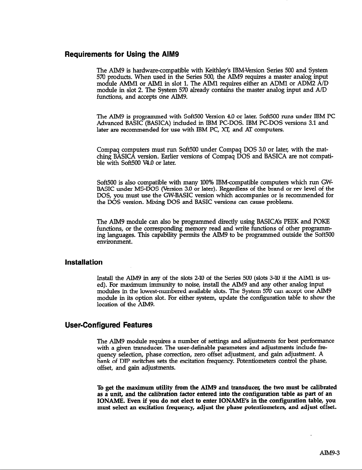
An Lm or RVDT generally has two secondary signal windings (A and B), a primary
winding for excitation, and a movable core. The primary and secondary windings com-
prise a transformer. The amplitudes of voltages induced into windings A and B vary in-
versely with each other as the core is moved.
You can connect a transducer’s signal windings to the AIM9 in a number of configura-
tions. The series-opposing connection (Figure 2) allows linear measurement of the core
position to either side of the center (null) position. At one extreme of the core’s move-
ment, the AIM9 output will be negative. At the other extreme, the AIM9 output will be
positive. The terminals for “winding A Ground” and ‘Winding B Ground” are not us-
ed for the series-opposing configuration.
AIM9-4
Page 5
TYPICAL LINEAR VARIABLE DIFFERENTIAL
TRANSFORMER TRANSDUCER
A
EXCITATION
IRON CORE DEMODULATOR
OISPLACEMENT-e
OUTPUT
VOLTAGE
OUT-PUT
VOLTAGE
SECONDARY
AC SIGNAL TO
-+DISPLACEMENT
>
B
Figure 2A. LVDT Series-Opposing Connection to AIM9, with Corresponding
Signal Variation
AIM93
Page 6
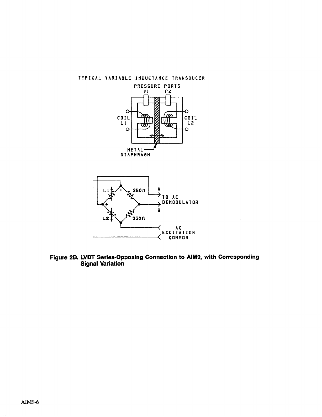
TYPICAL VARIABLE INDUCTANCE TRANSDUCER
PRESSURE PORTS
Pl
P2
1
METAL--+
DIAPHRAGM
tz4
< COMMON
J
Figure 2B. LVDT Series-Opposing Connection to AIM9, with Corresponding
Signal Variation
AIM9-6
Page 7
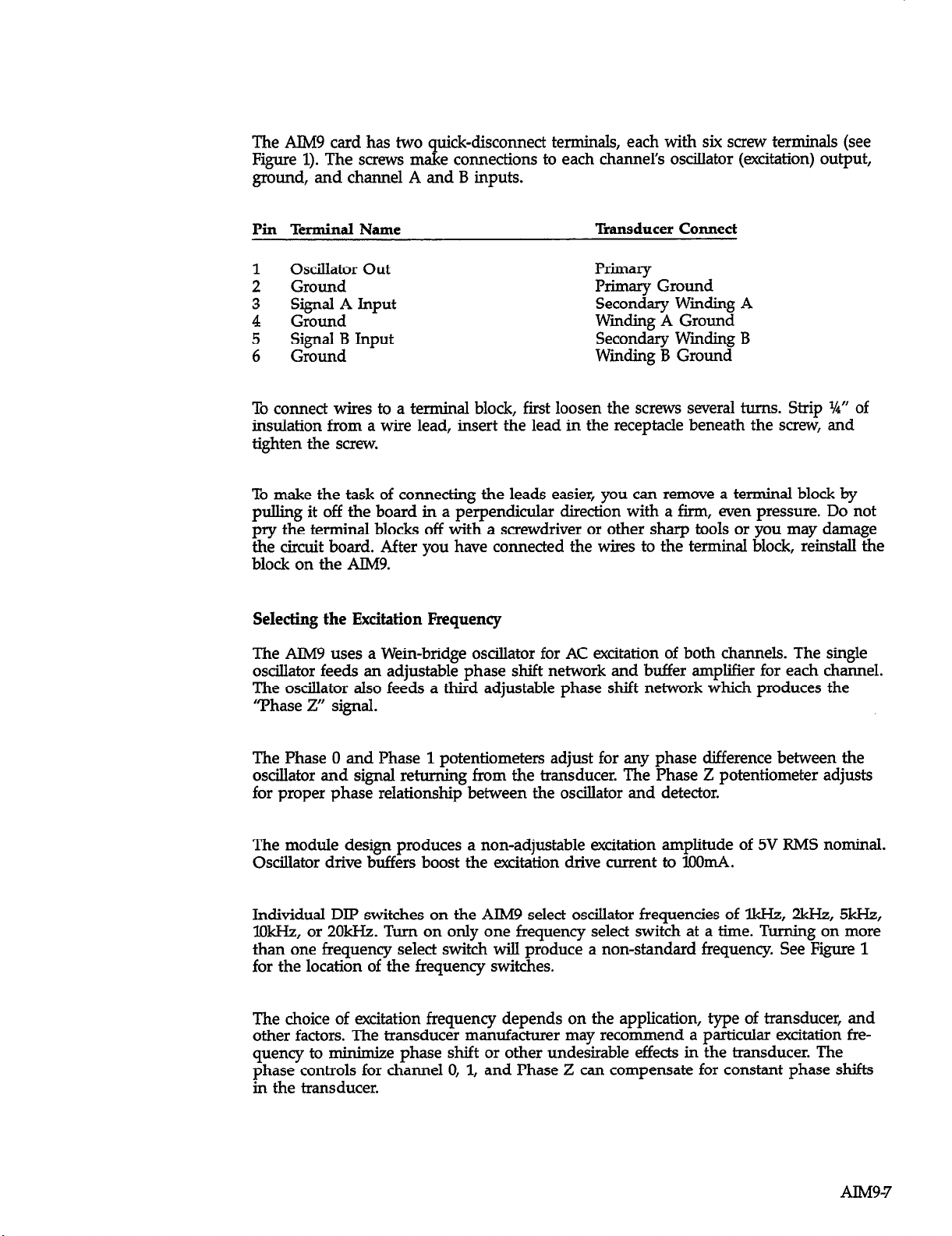
The AIM9 card has two quick-disconnect terminals, each with six screw terminals (see
Figure 1). The screws make connections to each channel’s oscillator (excitation) output,
ground, and channel A and B inputs.
Pin Terminal Name
Oscillator Out
:
Ground
3 Signal A Input
4 Ground
5 Signal B Input
6 Ground
To connect wires to a terminal block, first loosen the screws several turns. Strip %” of
insulation from a wire lead, insert the lead in the receptacle beneath the screw, and
tighten the screw.
To make the task of connecting the leads easier, you can remove a terminal block by
pulling it off the board in a perpendicular direction with a firm, even pressure. Do not
pry the terminal blocks off with a screwdriver or other sharp tools or you may damage
the circuit board. After you have connected the wires to the terminal block, reinstall the
block on the AlM9.
Selecting the Excitation Frequency
The AIM9 uses a Wein-bridge oscillator for AC excitation of both channels. The single
oscillator feeds an adjustable phase shift network and buffer amplifier for each channel.
The oscillator also feeds a third adjustable phase shift network which produces the
“Phase Z” signal.
Transducer Connect
Primary
Primary Ground
Secondary Winding A
Wmcbng A Ground
Secondary Wmding B
Winding B Ground
The Phase 0 and Phase 1 potentiometers adjust for any phase difference between the
oscillator and signal returning from the transducer. The Phase Z potentiometer adjusts
for proper phase relationship between the oscillator and detector.
The module design produces a non-adjustable excitation amplitude of 5V T&IS nominal.
Oscillator drive buffers boost the excitation drive current to 1OOmA.
Individual DIP switches on the AIM9 select oscillator frequencies of &Hz, 2kHz, 5kH2,
lOkHz, or 2OkHz. Turn on only one frequency select switch at a time. Turning on more
than one frequency select switch will produce a non-standard frequency. See Figure 1
for the location of the frequency switches.
The choice of excitation frequency depends on the application, type of transducer, and
other factors. The transducer manufacturer may recommend a particular excitation fre-
quency to
phase controls for channel 0, 1, and Phase Z can compensate for constant phase shifts
in the transducer.
minimize phase shift or other undesirable effects in the transducer. The
AlM9-7
Page 8

Where the transducer measures simple displacements of an otherwise static element,
there is no implicit advantage to using any given frequency. Unless the transducer
manufacturer recommends a specific frequency, set the AIM9 for 5kHz.
Measuring the displacement of a vibrating element requires a careful evaluation of the
vibration frequency, type of vibration, filter, and sampling rate. Generally, the excitation
frequency should be at least ten times the vibration frequency of the element being
monitored with the transducer.
Driving Multiple AIMS’s From One Master Oscillator
If you operate more than one AIM9 in a Series 500, you may need to drive all AIM9 ex-
citation circuits from the oscillator of one AIM9. This will assure that the excitation
delivered to all transducers is at precisely the same frequency.
The AIM9 has a single jumper for setting the oscillator in either master or slave mode
(see Figure 1). With the jumper in the master position, the AIM9’s oscillator drives its
own excitation circuitry and a common daisy-chain line in the Series 500 bus. Placing
the jumper in the slave position disconnects the ATM9’s oscillator from the phase shift
and buffer circuits, and connects this excitation circuitry to the daisy-chain line in the
baseboard.
To operate several AIM9 modules from one oscillator, first refer to Figure 1. For the the
master AIM9, install the jumper block on the center and left-most pins of Wl. To make
an AIM9 a slave, install the jumper block on the center and right-most pins of Wl. The
daisy-chain line in the-&r&s 5QO baseboard bus automatically makes the proper connections between the master and slave AIM% whenthes<‘modules a.r~plugged-iriIo
the Series 500.
Adjusting the Phase 0, Phase 1, and Phase Z Potentiometers
The phase adjustments permit the relative phases of the channel 0 and channel 1
return signals to be aligned with each other and Phase Z. The Phase 0 and Phase 1
potentiometers control the phase of the excitation for channel 0 and channel 1 relative
to the oscillator. The Phase Z potentiometer controls the phase shift of a third oscillator
signal used by the AIM9 demodulator (detector). The phase potentiometers give an adjustment range of approximately 170’ at the lkH2 excitation frequency.
The need for phase adjustments becomes clearer if one considers a simple LVJYI’
measurement. In practice, the AIM9 excites the transducer which returns AC waveforms
to the AlM9 “Ai’ and “5” inputs. The amplitudes of these waveforms vary inversely
with each other depending on the displacement of the Lvllvr core.
As is often the case, the return waveforms may experience some phase shift relative to
the oscillator, and to Phase Z which represents the oscillator waveform. For proper
decoding of the signals returning from the transducer, the phase-sensitive ATM9 detector circuit requires that the transducer signals be properly aligned relative to Phase Z.
The Phase 0 and Phase Z adjustments provide for this alignment.
AIM9-8
Page 9

When two transducers are used, there may be a need to align the phase angles of the
channel 0, channel 1, and Phase Z waveforms. The separate phase controls for each
channel and Phase Z gives a broad range of adjustment between the channel 0 and
channel 1 input signals and Phase Z.
You must use an oscilloscope to adjust the Phase 0, Phase 1, and Phase Z potentiometers. Wth the transducer connected to the AlM9, monitor the test point DElU
with the oscilloscope. The signal level at DE’IU will be on the order of 5OmV45OmV
depending on the degree that the LVDT core is off-center electrically. If the output of a
transducer is zero, the waveform will be a straight line or nearly so. If this is the case,
move the transducer off electrical center to provide a workable waveform at DETO.
For channel 0, adjust the Phase Z and/or Phase 0 potentiometers to produce a
waveform at DETO resembling Figure 3. There will be an adjustment range for both
potentiometers wherein either will correct an out-of-phase condition. UltimateIy you
may turn one or the other potentiometer beyond the point where it has any effect, and
it will no longer be possrble to achieve alignment. Therefore, the adjustment may require some trial-and-error to find the best positions for each potentiometer. You may
have to turn each potentiometer lock-to-lock to find its active range.
Once set, the phase potentiometers should require no further adjustment unless you
change the excitation frequency or the orientation of the transducer.
For two-channel operation, first adjust Phase 0 and/or Phase Z for the proper waveform
at test point DETO. Next, monitor test point DETl and adjust Phase 1 for the proper
waveform at test point DETl. You may have to readjust Phase 0 or Phase Z to find the
potentiometer positions which mutually align the waveforms at DETO and DETl.
AlM9-9
Page 10

-OR-
1RELATIVE
POSITION
t UNIMPORTANT
UNIMPORTANT
AIM940
Figure 3.
Waveform at Test Point DETO or DETl with Properly Adjusted
Phase Controls
Adjusting
The offset
trical “zeros” of a transducer do not coincide. In such a case, the transducer may produce a net output signal even though it is positioned at mechanical zero. The AIM9 offset potentiometers OS0 and OS1 adjust the offset for channels 0 and 1, respectively.
The easiest method of adjusting offset is to use a Soft500 program to read the offset
directly.
(Perform this step only after you have connected the transducer to the AIM9 and
adjusted the phase controls.)
To read the AIM9 offset with Soft500, first make sure the transducer is at mechanical
zero. Turn the gain amplifier GAIN0 potentiometer fully CW for maximum gain. bad
and run the following short program. Adjust the offset potentiometer for a reading of
zero volts.
the Offset
adjustment sets the output of the AlM9 to OV when the mechanical and elec-
Page 11

10 cls:VA=O
20 call init
30 call ioname’(“offseY,8,OJZ,l)
40 call anread’(“offsetJ,va,l)
50 locate 1,l:print va;” millivolts
60 goto 40
The program assumes an AIM9 in slot 8, with the transducer connected to channel 0.
A/D accuracy is 12, and global gain is 1. The IONAME is “offset”. The program returns
the reading “WY in millivolts (EUF%=l).
As written, this program can accommodate a signal input of up to XIV. After you have
made a coarse adjustment of offset, increase the sensitivity of the adjustment by increasing the global gain GA% parameter (last in IONAME) to 2, 5, or 10. Repeat the offset adjustment until no further improvement can be made.
The programs later in this manual all make an initial reading of offset and use the
reading to correct subsequent measurements. This technique can be used to compensate
for any residual offset.
Selecting the Filter
The AIM9 includes a 5-pole, 3OdB-per-octave low-pass filter with selectable cutoff fre-
quencies of 2Hz, 2OHz, and 2OOHz. The primary function of the AIM9 filter is to
remove the excitation carrier from the transducer return signal.
The best filter setting for a given application depends on a number of factors. While the
2H.z filter may often give the best results, this is not always the case.
First, the selected filter frequency should be no greater than one tenth the excitation
frequency. Practically speaking, the 2OOHz filter should not be used with lkHz excita-
tion since the ratio is only 1:5. Any other combination of AIM9 filter and excitation frequency passes the 1:lO test.
Second, the filter frequency should be higher than the frequency of the signal being investigated. For displacement readings of a non-vibrating element, the 2Hz filter would
generally be preferred. Measuring the displacement of an element which itself is
vibrating requires a filter setting at least five times the fundamental vibration frequency.
The maximum usable filter frequency depends on the vibration frequency, type of
vibration, and A/D sampling rate. Avoid sampling at too low a rate for a particular filter
setting, or aliasing may result.
The IONAME FIIT% parameter programs the filter. This parameter is part of the expanded IONAME command structure of Soft500 Version 4.0. The values for FIIT% are 0
for 2Hz, 1 for 2OH2, and 2 for 2OOHz. The 2OHz filter is the default selection. The filter
function affects both channels, and cannot be disabled. Howevm, FIIT% can specify a
different filter frequency for each channel.
AIM9-11
Page 12

Consult the Soft500 IONAME documentation for information on specifying parameters.
Note that beginning with Soft500 Version 4.0, you can specify IONAME’s as part of the
software and hardware configuration process.
Setting the Gain
Each channel of the AIM9 module contains a gain buffer stage which amplifies the
signal immediately before it is multiplexed to the Series 500 or System 570 bus. Each
gain amplifier has a gain potentiometer which provides a continuous adjustment from
xl to x20. These gains correspond to a full-scale voltage input range for the AIh49 of
*lov to f0.5v.
The best setting of the gain potentiometer gives a full-scale output at AIM9 test point
A0 (Al for channel 1) that fits the AID input range. The global gain GA% also influences the setting for the AIM9 gain adjustment. Global gain sets the maximum input
signal that the master analog input module (AIM1 or
As an example, the range of voltages from an Lm might span &l5OmV. By setting the
gain potentiometer for progressively higher gains, the AIM9 gain amplifier could boost
the voltage at test point A0 anywhere from fl5OmV up to @V (see Figure 4).
Ah4Ml) can handle.
I
I Ov~50mv MAX
I
1
ov
I+ l 1 50mV
K A0
I
I
I
L
*OUTPUT IS
NEGATIVE FOR
NEGATIVE
DISPLACEMENT
-----
1
1
+--mM-m---,r-----
AIM 9
OF LVDT CORE. 1
----
1
2v
MAX
TEST
POINT
T’
I
I
I
I
I oET;pyA$-JG-&)
I
I
I
I
I
I
AIM942
I
I
I
I
--------
Figure 4. Effect of Gain, Global Gain, and A/D Range in the AIM9
AIM 1
Page 13

With the factory-default A/D range, the maximum signal that the A/D converter can accept from the master analog input module (AIM1 or AMMl) is flOV. A global gain
(GA% of 5 would give the AMMl or AIM1 an input sensitivity of &?‘V for *lOV fullscale output. To match this input range, the signal at AIM9 test point A0 should not exceed *2.UV with maximum transducer displacement. An AIM9 gain adjustment of approximately x14 gives a &2V signal at AO. If the GA% parameter were programmed to
X10, the maximum voltage permissible from the AIM9 would be would be *lV.
In practice, the AlM9 gain is adjusted for a desired output voltage at A0 without regard
for the absolute gain factor which results. The test program included in the section on
calibration factors will aid you in adjusting the gain potentiometer.
Software Considerations
Beginning with Version 4.0, Soft5003 IONAME command gives full control of all AIM9
operating parameters. The format of IONAME when programmed specifically for the
AIM9 is as follows:
CALL IONAME’( ION$, SLOT%, CHAN%, ACC% [,GA%][,FILT%] )
The IONAME command specifies global gain GA% for a given slot and channel. The
AIM1 nr AMMI nmo-rammahl~ uain nmnlifbr annlien thp ulnhal cwin & th-hp s&g-&
L-.bA -a *-.-.*,.. r’vc)‘-- .--*- b-- -.r-*-’ -rr--.. -.- b ----- p--
before the signal is digitized by the A/D converter module.
The FILT% parameter selects the 2Hz, 2OH2, or 2OOHz filters. The values for FII.T% are
0 for 2Hz, 1 for 2OH.2, and 2 for 2OOHz. The 2OHz filter is the default filter. If you do
not program FIIT% specifically, IONAME assumes the default value of 1. The filter
function affects both channels, and can not be disabled. However, FlLI’% can specify
different filter frequencies for different channels.
Entering a Calibration Factor into the Configuration ‘Igble
Soft500 V4.0 and later versions can accept a transducer calibration factor as part of an
IONAME. For an LVM; this factor is usually expressed as:
millivolts signal I volt excitation I units of displacement
(l5On-W I V I 1 cm, for example)
For other Series 500 modules, entering an IONAME and calibration factor into the configuration table is not mandatory, although it does simplify the test programs and the
unit conversion process.
For the AIM9, automatic conversion of voltages to measured units requires that you set
up IONAME’s in the configuration table. The IONAME for a channel must contain the
calibration factor for the transducer connected to that channel. This practice enables you
to use the Engineering Unit Flag 80 in ANREAD or ARGETVAL commands. EUF%=80
will return displacement readings directly in the measured units of the calibration
factor.
AIM9-13
Page 14

Calibrating an AIM9 and liansducer
Normally, LVDT and RVDT transducers do not include a precise calibration factor. Ex-
citation amplitude, frequency and waveform, hardware gain, and other variables make
only nominal calibration factors possible.
You can derive an accurate calibration factor for a transducer by
using a displacement calibration standard (micrometer) and a few simple calibration
procedures. The following example program calibrates an LVlYT. Calibration of an RVDT
would be similar, except that the calibration would be angular, rather than linear
displacement.
Before you proceed with this program, connect the transducer to the AIM9’s channel 0
terminals. Make sure the AIM9 is set to the excitation frequency suggested for the
transducer. If a specific frequency is not suggested by the manufacturer, set the AIM9
for 5kH.z.
The program assumes that the AIM9 is in slot 8, with transducer connected to channel
0. Twelve-bit AID is specified. This program also produces an optimum setting for the
GAIN0 potentiometer. This setting fits the fulI-scale displacement of the LVDT to the
selected global gain and A/D range of the system. Before you run the program, turn the
GAIN potentiometer for channel 0 fully CW to select maximum gain. This will aid in
setting the offset.
10
KEYOFF
20
CLS:LOCATE 3,5:l?RINT” PROGRAM WHICH GENERATES A CALIBRATION
FACTOR FOR AN LVDT’
LOCATE 10,5:INl?UT’What is the desired global gain (1, 2, 5, or lO)“;GA%
30
40
LOCATE l2,ti:INPUT”What is the calibrating displacement (number only)“;D
LOCATE 14,5:INPUTWhat are the units of measure (in, cm, mm, etc.)“;U$
50
60
LOCATE l6,5:lNPUT”What is the maximum displacement you anticipate (number
0nlyy;MAx
70
CLS
80
I Adjust phase
90
CLS
LOCATE l,l:PRINT”Connect the input of an oscilloscope to the test point DETO on
100
the“
llo
LOCATE 2,1:l?RINTXIM9. Adjust the Phase 0 and/or Phase Z potentiometers to
get a wavefod’
LOCATE 3,1:l?RINT”resembling an unfiltered full-wave rectified sine wave (manual
I20
Figure 3)!’
LOCATE 7JO:PRINT “When adjustment is completed, press any key to continue.
130
140
IF INKEY$=““THEN 140
CLS
voFL=o:voEH=o:vCAL=o
Ei
170
’ Call INIT and set up IONAME’s
180
CALL INIT
190
CALL IONAME’(“OFFSETIXO,l2,l,l)
200
CALL IONAME’(“OFFSETH’73,O,l2,lO,1)
210
CALL IONAME’(‘VOrsrs’~,O,l2,ga%,l)
220
LOCATE 3,l:PRINT “Move the Lm to mechanical zero.”
230
LOCATE 5,1:l?RINT”LOW-GAIN Adjust: Adjust the channel 0 OFFSET pot for a
reading of 0:’
240 LOCATE 9,1:lXINT “After offset is 0, press any key to continue. . I’
CALL ANREAD’(“OFFSETL’,VOFL,O)
250
260 LOCATE 7,lPRINT “Offset = “;VOFL;” volts
I,
AlM9-14
Page 15

270 R$=INKEY?$:IF F@=“‘THEN 250
280 LOCATE 5,1:PRINT”HIGH-GAIN Adjust: Trim the channel 0 OFFSET pot for a
reading of 0.”
290 LOCATE 9,l:PRINT “After offset is 0, press any key to continue. . I
300 CALL ANREAD’(“OFFSETH’~OFH,l)
310 LOCATE 7,l:l’RINT “Offset = “;VOFH;” millivolts
320 R$=INKEY$:IF W=“‘THEN 300
330 ’ Read calibrating displacement
340 CLS
350 LOCATE 1,1:PRINTPRINT “Move the LVDT core to”‘;D;U$;” for calibration.”
360 LOCATE 3,lPRINT “Adjust the channel 0 GAIN pot until reading equals
“;(10000/GA%)*(D/MAX)+VOFH;” millivolts”
370 LOCATE $1:PRINT ‘Tress any key when adjustment is completed:’
380 CALL ANREAD’(“VOITS’~CAL,l)
390 LOCATE 5,lPRINT “Calibration voltage = “;VCAL;” millivolts
400 R$=INKEY$:lF R!$=““THEN 380
410 CLS
420 cl? = (VCA~VOFI-I)/5
430 PRINT “Cal Factor = N*
440 END
The program initially asks for the calibration displacement and for the maximum
displacement that is expected. The calibration displacement is the precise distance you
will move the LVDT core during calibration. The maximum displacement is the greatest
distance that the Lm core will move during actual measurements, and may not be
known precisely at this time. If you don’t have a good idea of the maximum displacement, estimate on the high side and continue the calibration.
,CF;“mV signal I V excitation /“;D;U$;
I,
m
Transducer manufacturers normally specify a “full-scale” displacement for an Lm as
part of a nominal calibration factor. Such a full-scale value represents the maximum
permissible displacement for the transducer. Core movement beyond the suggested fullscale displacement may give inaccurate readings, and may damage some types of
transducers. For the purposes of this program, neither the calibration displacement nor
the maximum expected displacement should exceed the manufacturer’s suggested fullscale displacement. The calibration displacement you apply must be less than or equal
to the maximum displacement you expect.
This program provides for adjustment of the phase potentiometers. As instructed,
monitor the test point DETO with an oscilloscope and adjust the Phase 0 potentiometer,
Phase Z potentiometer, or both, to achieve a waveform resembling Figure 3. If the
waveform appears to be a straight or slightly wavy line, first try a more sensitive input
range on the oscilloscope. The signal will probably be in the range of 5OmVl5OmV. You
can also change the displacement of the LVDT to provide a higher amplitude signal for
this adjustment. Any offset of the waveform is not relevant to this adjustment.
The program prompts for an offset adjustment in two stages: a low-gain adjustment at a
gain of 1, and a high-gain trim at a gain of l.0. Before you adjust offset, turn the gain
potentiometer fully CW (maximum gain position). During offset adjustment, you may
not be able to obtain a reading of precisely 0. More often, the best that can be done is a
flashing polarity sign and a reading of a few millivolts or less.
The program includes an adjustment for AIM9 gain. Unlike the global gain (GA%)
parameter, the A&W’s gain is not programmable or readable through software. This ad-
AIM945
Page 16

justment sets the level of the signal after it has been demodulated and filtered, and
before it is routed to the master analog input module. With insufficient gain, the
reading may suffer in resolution and accuracy. Excessive gain will cause the input signal
to saturate the AIM9 gain amp or the AlMl/AMMl programmable gain amp. If you encounter either condition, alter the GA% parameter, or adjust the AlM9 gain potentiometer accordingly.
The ideal setting for the GAIN0 potentiometer is one where the maximum expected
displacement of the transducer produces an AIM9 output equal to the input range of
the AlMl or AMh41. The calibration program automatically calculates the gain setting
which matches the transducer output to the analog input range. The calculation uses
your estimate of maximum displacement, and assumes that the A/D range is the factory
default slOV
This program produces a calibration factor expressed as millivolts of signal per volt excitation per units of displacement. The cal factor applies only to a transducer/AIM9
calibrated pair. Its cal factor may not agree with any calibration factor suggested by the
transducer manufacturer. This is because the amplification applied by the AIM9 gain
amplifier is included in the calibration factor.
The program uses the nominal excitation value of 5V RMS to calculate the cal factor.
The long-term stability of the excitation is more important than its precise amplitude.
As such, any slight difference between the actual excitation level and the presumed
5V RMS has no practical effect on the accuracy of the cal factor.
The calibration factor must be entered into the configuration table as part of an
IONAh4E. The CONFIG.EXE program’s CHANNEL SETUP asks for the calibration fac-
tor in millivolts per volt. The cal factor can be entered to three decimal places.
After receiving the cal factor, CHANNEL SETUP asks for full-scale units. Enter the
measured units of linear displacement applied to the transducer during calibration, not
the maximum expected displacement or the manufactureis suggested full-scale. The
full-scale units must be entered as an integer. Therefore, only whole units of displacement should be applied for calibration.
As an example, you may have calibrated an LVDT at 5cm of displacement. The calibration program might return a cal factor of l55.2138mV I volt I 5cm. Enter “155.214” as the
calibration factor, and “5” for full-scale units. Subsequent readings of unknowns
using ELF%=80 will be expressed as centimeters.
After you complete the calibration program and have entered the resulting cal factor in-
to the calibration table, run a test program and make a few measurements. Judge
whether your original estimate matches the actual maximum displacement of the Lm
core. If the estimate was too high, you can rerun the calibration program with a smaller
maximum displacement value based on your measurements.
NCYTE: The calibration factor derived with this program applies
only to the transducer and AIM9 which have been calibrated as a pair. Calibration must
be repeated if the gain, phase, or excitation frequency are changed. Calibration must
also be repeated if the transducer or AM9 are replaced.
AIM9-16
Page 17

AIM9 Example Programs using a CAL Factor and IONAME in the Configuration Table
The following short programs demonstrate the simplicity of reading an LW directly in
measuring units (centimeters, in this case) once you have entered the cal factor into the
configuration table. For this example, the cal factor of a hypothetical LVDT was found to
be 60.6mV I V I lcm and entered into the configuration table as part of an IONAME.
The IONAh4E includes the following other parameters: ION$=“dist”, SLOT%=8,
CHANNEL%=O, ACC%=l2, GA%=lO, and FII.T%=l.
These programs assume that the gain and phase adjustments have not been altered
from those settings made during initial set up and calibration of the AlM9.
The first program uses ANREAD. It reads the residual imbalance of the LVDT at
mechanical zero, and provides an opportunity to trim the offset potentiometer. The program saves the final offset and uses it to correct subsequent readings of displacement.
Use of EUF%=80 in the ANRFAD’s of offset (“OF”) and signal (“VA’) yields readings in
centimeters. The difference between VA and OF is the corrected displacement of the
LVDT core.
20 CLS
30 CALL INIT
40 VA=O:OF=O
50 LOCATE 1,1:PRINT’Xeading offset - Adjust offset potentiometer for a reading of 0”
60 LOCATE 6,l:PRINT’Tress any key to continue. . . ”
70 CALL ANREAD(?lisi$0f,80)
80 lXXATE 3,1:PRINT”Equivalent Offset = “;OF;” cm
90 R$=INKEY!j:IF W=““THEN 70
loo CLS
110 LOCATE 1,lPRINT”Reading displacement - press any key to exit”
120 CALL ANREAD’f?list?,va,80)
130 LOCATE 3,1:PRI$IT ?&splacement = “;VA-OF;” cm
140 R$=INKEY$:lF R!$=““THEN 120
150 END
N
N
The next program uses the ANIN command to read 20 values and write them to an array. It also demonstrates how to retrieve data values from the array directly in measuring units using ARGETMAL with EUF%=80. The IONAMF information for “dist” from
the previous example also applies to this program.
The program first uses an ANFEAD to read the offset of the LVDT at mechanical zero.
The offset reading is used to correct the subsequent measurements made with the
ANIN command. The EUF%=80 in the ARGETVAL statement yields readings directly in
centimeters.
20 CLS
30 CALL INIT
40 KEY OFl?VA=O:OF=O:SlX=O
50 LOCATE 1,l:PRINT”Reading offset - Adjust offset potentiometer for a reading of 0”
60 LOCATE 6,1:PRINT.‘Tress any key to continue. . .”
70 CALL ANREAD’(?lW,0f~0)
80 LOCATE 3,l:PRINT”EquivaIent Offset = “;OF;” cm ”
90 R$=INKm:IF R!§=“‘THEN 70
AIM947
Page 18

100 CLS
110 LOCATE 1,lzPRINT’Apply displacement - press any key to take reading”
120 R!$=INKEYS:IF R$=““THEN 120
130 CALL ANIN’(“aryW,20.,“dist’~l,“done”)
140 CALL INToN’(1001’mil”)
150 CALL STATUS’(“done’,stat%)
l6OlFSTAT%<>OTHENl50
370 CALL INTOFF
180 CLS
190 LOCATE 1,l:PRINT “Sample -----
200 FOR T=l TO 20
210 CALL ARGETVAL(“ary%‘:tl’dist’:va,SO)
220 PRINT WA-OF
230 NEXTT
240 END
Calibration Directly Within a SOFT.500 Program (No IONAME in the Configuration
Table)
Another method is available for reading a transducer displacement directly in measure-
ment units. It does not require that an IONAME or calibration factor be entered into
the configuration table. Instead, calibration is done within the program. This type of
program does not use Engineering Unit Flags, but relies on multiplying the voltage
reading times a conversion factor to yield displacement.
cm “
You must apply a calibrating displacement to the transducer each time you run the pro-
gram. The following example program uses a 3cm distance to calibrate an LVDT. The
program assigns a variable “CON” to the calibration factor it generates. CON equals the
3cm calibration displacement divided by the number of millivolts generated at this
displacement. CON is valid as a calibration factor until the program is terminated, or
unless some other number is assigned to CON.
The IONAME commands have been set up for an LVDT connected to channel 0 of an
AIM9 in slot 8. A/D ACC%=l2, and FIIT%=l (2OHz). A gain GA% of 10 is used for
offset adjustments, and a GA% of 2 is used for LVDT measurements.
The program assumes that you have already used an oscilloscope to set the phase adjustments. It also assumes that the GAIN0 control has been set to give a suitable fullscale output from the AIM9. To fine-tune this program and cal procedure to specific applications, you may need to alter the IONAME! GA% parameters, the AIM9 gain, or the
calibration distance.
20 CLSKEY OFF
30 CALL INlT
40 CALL IONAME’(“offset’~8,O,l2,lO,l)
50 CALL IONAME’(“calib’,8,O,l2,2,1)
60 VA=O:OF=O:CON=O:CAL=O
70 LOCATE l,l:PRINT?Mjust Offset for 0 then press any key to continue”
80 CALL ANREAD’(“offseV,of,l)
90 LOCATE 3,l:PRINT”Offset = “;OF;” millivolts
100 R!#i=INKEtY$:lF R$=““THEN 80
llo CLS
120 LOCATF 1,l:PRINT”Calculating conversion factor. Apply 3cm displacement and
press any key.”
N
AIM948
Page 19

130 CALL
140 R$=INKEY$:IF R!J=““THEN 130
150 CON=S/CAL
l.60 CLS
170 UXATE 1,l:PRINT”Reading displacement. Move LVDT core to desired position.”
I80 CALL ANREAD(“calib~va,l)
190 LOCATE 3,l:PRINT (vA-OF)*CON;” cm
200 LOCATE 8,kPRINT’Tress spacebar to exit”
210 R$=INKEY$:IF R!$=” ” THEN END
220 GOKI 180
230 END
ANRl3w(%lliw,cal,l)
Service and Calibration Information
The AIM9 module does not contain any user-serviceable components or calibration
screws. Therefore, normal troubleshooting consists of simple signal checking and
substitution of a known good module for a suspected module.
A module which malfunctions should be returned to Keithley for service or replacement. If you have access to a repair facility which is skilled in repair of multilayer
boards, you may elect to have repairs done locally, rather than by Keith@ If so, note
the following:
N
NCYI’E: The AIM9 module uses a multi-layer circuit board. Repair of multi-layer boards
requires special care. Keithley recommends that you return the AIM9 to the factory for
repair.
All components on the AIM9 are soldered in position. As a rule, you cannot replace a
component soldered to a multi-layer board and guarantee the integrity of connections
made through the internal board layers. Many of the traces on the AIM9 board are narrow and can be damaged by excessive heat during desoldering. A module so damaged
by the user may not be repairable by Keith@ Damage through improper repair may
void the warranty.
Troubleshooting the AIM9
The following checks will show whether a problem exists with the AIM9 module. As a
first step in troubleshooting a malfunctioning AlM9kransducer system, make sure the
transducer is in good condition. An ohm meter can be used to check for continuity of
the windings in an RVDT or Lm Other types of AC-driven transducers may not be
checkable with an ohmmeter.
The AIM9 contains 16 test points. Only a few of the test points are monitored during
normal set up and operation. The most-used points include DE‘IB and DET 1, A0 and
Al, and GND. The remaining test points provide information about the operation of the
various AIM9 circuits for the purpose of troubleshooting. Check these points sequentially, starting at the first stages of the AlM9, according to Table 1 and Figure 5.
Before you perform these tests, you must make a transducer simulator and connect it to
the A0 and BO inputs of the AIM9 channel 0. The simulator consists of four resistors,
AIM9-19
Page 20

connected as shown in Figure 5. Connect this simulator to the AIM9 quick-disconnect
terminal block.
If all signals on the AIM9 check out correctly, the problem may lie with the transducer
or elsewhere in the data acquisition system.
+ 1500n 4 won
GNDb
Figure 5. Transducer Simulator for AIM9 Troubleshooting
AIM9-20
Page 21

Table 1. AIM9 Test Points, Signals, and Functions for Channel 0 (CHANNEL 1)
Test Point Waveform
OV (straight line)
Sine wave with period =lOOpsec
(f = 1OkHz). 14.14V AC p-p.
AGC
so, (W
DETO, (DETI)
co, (Cl)
DO, @l)
L
D
AO, (Al) with
no input.
AO, (Al) with
input.
AN0
OV (straight line)
Sine wave with period =lOOpsec
14.14V AC p-p.
Full-wave rectified, unfiltered AC.
Adjust Phase 0 (Phase 1) or Phase
Z if necessary proper waveform see Figure 3. Period=lOO~ec.
Slightly disjointed sine-wave 3.75V Output of detector stage. Slight
AC p-p Period =lOOpsec.
Square wave with rounded corners Input of l-bit AID
1V p-p. Period = lO!$sec.
Square wave 3.5V p-p Period
=lOOpsec.
DC. Remove transducer simulator
from AIMS. ,Check that offset adjustment pot for (+) and (1) voltage
range adjustment. Set to OV.
DC. Replace transducer simulator. Output of gain amplifier
Check range of GAIN pot. Output
should be adjustable to approx.
-llV DC.
DC, same as A0 (Al). See note
below.
Function
Tie point to analog ground.
Output of Wein Bridge oscillator.
First check alI frequency switches
for proper operation. Then select
1OkHz excitation.
Automatic Gain Control for Wein
Bridge.
Phase-shifted and buffered output
of oscillator. Turn Phase 0 (Phase 1)
pot and check for phase shift.
Output of subtractor stage.
adjustment of Phase 0 or Phase Z
will break the waveforms.
Output of l-bit A/D
Output of gain amplifier
Output of AIM9 immediately
before signal is transmitted to the
system bus.
NOTE: To switch A0 or Al to output ANO, run BASICA and enter:
DEF SEG=&HCFFO : PORE CMDA,CH
CMDA
sLoT#
2 MI82
3 84
4 86
5 88
6 8A
8’
9 90
10 92
ADDR
SC
SE
AlM9-21
Page 22

Where:
CFFO is the base address of the system interface card. If you set the interface to reside
at another base address, use that address in place of CFFO.
CMDA is the slot-dependent address of the slot where the AIM9 resides. See the
Series 500 baseboard documentation for a complete list. For System 570, CMDA for
the option slot is &HSE.
CH is the channel number, either 0 or 1.
Examples:
With interface at &HAFFO, a command to switch channel 1 output to the test point
AN0 of an AIM9 in slot 8 would be:
DEF SEG=&HAFFO : POKE &HSE,l
With interface at CFFO, a command to switch channel 0 output to the test point AN0
of an AIM9 in slot 5 would be:
DEF SEG=&BCFFO : POKE &HSS,O
Table
D3 D2 Dl DO Data Selection
x x x 0 Channel 0 Channel
t 0 x x
i
2.
Data for Peaks and Pokes to CMDA of AIM9 Slot
Function
x x 1
:: x
ii
Channel 1
Filter cutoff is 2OOHz
X
Filter cutoff is 2OHz Filter
Filter cutoff is 2Hz Frequency
Select
AIM922
Page 23

l -
P
o-
v .E
L
c
Figure 6. AIM9 Test Points
AlM9-23
Page 24

AIM9 Specifications
Input Characteristics
Input Channels (local): 2 differential and balanced to ground
Gain: Adjustable per channel, 1 to 20
Input Dynamic Range: f3.5V peak max without distortion
Input Protection: rtl5V max (powered)
Input Resistance: lOOka each input to common
Common Mode Rejection: 60dB @ 60Hz
Nonlinearity: 0.05% of full scale
Quadrature Balance Range: adjustable, *90°
Phase Balance Range: adjustable, &l25mV @ xl gain
Bandwidth: software selectable five pole filter (-3dB), 2, 20 or 200Hz
Settling Time (to 0.01%): 2Hz
Noise: (residual carrier with 1O:l or greater oscillator to filter ratio), lmV p-p
Temperature Coefficient:
Gain: 20Oppml’C
Offset: lOOppm/“C
Excitation Characteristics:
flOV max (unpowered)
ZOOOms
2oHz
2ooHz
lOOISIS
2om.s
Frequency: selectable per system, lk, 2k, 5k, 1Ok or 20kHz with master/slave synchroni-
zation for up to l.0 modules
Frequency Accuracy: rt3%
Amplitude: 5V RMS &lo%
Third Harmonic Distortion: 1%
Amplitude Stability versus Load (lOOn mm): .Ol%
Temperature Coefficient: Frequency: +20OppmPC
Amplitude: 4Oppml”C
Rower Requirements:
+l5Vdc
-1Rrdc 9omA (l25m.A)
+5Vdc 6OmA
6OmA (lOOmA)-No load (max loads)
AIM9-24
Page 25

AIM9 PARTS LIST
Part Number Title Remarks
500-480 Component Layout
FA-135
6-32x3/32 PPH 6-32 x 3/32 Phil Pan
C-23%.01
c-237-.1
c-237-1
c-3wl.O
c-314-250
c-347-1ooop
c-365-.1
c&47p
C-238-.01
C-347-8200~
C-389-.082
CS-521-5
cs-553
IC-227
IC-279
IC-320
IC-342
IC-381
K-504
IC-505
IC-506
IC-507
IC-508
IC-518
IC-517
R-263-1OOk
R-l7&lOk
R-263-93.1
R-76-lOk
R-76-lk
R-76-82
R-7675k
R-76-1OOk
R-88-237k
R-88-42k
R-88-10.5k
R-88-1OOk
R-88-1Ok
R-88-15/&
R-88-l58k
R-88-l&
R-88-200k
R-88-20k
R-88-3O.lk
R-88-30.9k
R-88-43k
R-88-7.5k
R-88-82.5k
Pem Nut
Head
Capacitor
Capacitor
Capacitor
Capacitor
Capacitor
Capacitor
Capacitor
Capacitor
Capacitor
Capacitor
Capacitor
Connector (6-p@
Connector (6-pin)
Int. Circuit (TL061)
Ont. Circuit (TLO62)
Int. Circuit (DG2ll)
Int. circuit (LF4ll)
Int. Circuit (ADG200)
Int. circuit (LF4l2)
Int. circuit (LM7905)
Int. Circuit (AM686)
Int. Circuit (LHOO02)
Int. Circuit (DG27l)
Int. Circuit (TXlO62)
Int. Circuit (74LSl75)
Resistor
Resistor
Resistor
Resistor
Resistor
Resistor
Resistor
Resistor
Resistor
Resistor
Resistor
Resistor
Resistor
Resistor
Resistor
Resistor
Resistor
Resistor
Resistor
Resistor
Resistor
Resistor
Resistor
zzfc9 Cl4 Cl9 c20 c22-C24, w, C33, C39,
C46, &7&9, &4, &C59
ClO, Cll, C28, C36-C38, C40
C51, C55, C56
Cl, c2
Cl2, Cl3, C16-Cl8, C31, C43
c3-c5, cl5, c50, C52. C53
C21, C25, C26, C60, C61
c45
c30, c41
C29, a2
JX J2
AO, Al, DIZTO, DETl, TPG, OSC, AGC, AN0
U6
u19
Ul3
U3, U4, W, U16, U22
U21
Ul, ulo, u14, u23
u2
US
us, ul7
us, ul5
ml, ul2
u20
R26, R27
RB-R21, R5%R60
R66
R17, R25, R31, R56
R55
R22, R34, R39, R61
R50
R23, R24
RS, R9
R52, R54
R32
R36, R38, R45, R63, R65
Rl5, R16
R4, R43
Rl, R40
R35, R37, R62, R64
R33
R47
R48
R3, R42
R46
R5, R44
R49
AlM9-25
Page 26

AIM9 PARTS LIST (CONT.)
Part Number
R-88-76.8k
R-76-lM
R-88-3.32k
RF-28
RP-89-1Ok
RP-89-lM
RP-89-200k
SW467
TP-102-2
TG-166
TG-84
SO-83-l
CC-38-2
cs339-3
CS-476
500-323
500321
500-322
500-322
632x7116 PPH
500486
Title Remarks
R2, R41
Resistor
Resistor
Rectifier
Potentiometer
Potentiometer
Potentiometer
Switch
Resistor Network
Transistor (J270)
Transistor (2N3906)
Socket
Cable Clamp
Connector
&p$;$G)
R53
R2843.30
CRl, CR2
R6, R7
RlO-Rl2
R’l3, Rl4
Sl
R51
t$, 43
wl
Clamp Assembly
QamP
Strip Rubber
Scotch 3M #4ll Tape
Strip Rubber
Scotch 3M #4ll Tape
6-32 x 7D.6 Phil Pan
Head Screw
Schematic
AIM9-26
Page 27

CC-38-21
cs-339-31
/7-
so-83-l
(4
RE0.D)
Jl
J2
 Loading...