

Tektronix KDAC500 Data Acquisition,Control Software Compiler Version Rev. C (UNSUPPORTED) User manual
Page 1

KDAC500
Compiler Version for IBM, COMPAQ, and
100% Compatible Personal Computers
Data Acquisition and Control Software
Publication Date: October 1991
Document Number: 501-915-01 Rev. C
Page 2

Copyright Notice
The KDAC500 software and this documentation are copyrighted with all rights reserved by
Keithley Instruments, Inc., Cleveland, Ohio. No part of this product may be copied or reproduced by any mechanical, photographic, electronic or other method without prior written
consent of Keithley Instruments, Inc.
The KDAC500 software, including all files and data, and the diskettes on which it is contained (the “Licensed Software”), is licensed to you, the end user, for your own use. You do
not obtain title to the licensed software. You may not sublicense, rent, lease, convey, modify,
translate, convert to another programming language, decompile, or disassemble the licensed
software for any purpose.
You may: a) use the software on a single machine; b) copy the software into any machinereadable or printed form only for backup in support of your use of the program on the single
machine; and, c) transfer the programs and license to use to another party if the other party
agrees to accept the terms and conditions of the licensing agreement. If you transfer the programs, you must at the same time transfer all copies whether in printed or in machinereadable form to the same party or destroy any copies not transferred.
The KDAC500 software has been thoroughly tested and the documentation reviewed. However, Keithley Instruments, Inc. does not warrant that the KDAC500 software will operate as
described in this manual in every hardware and software environment. Further, Keithley Instruments, Inc. does not warrant the performance of the product for any particular purpose.
In no event is Keithley Instruments, Inc. liable for any damages resulting, directly or indirectly, from the use of this product.
Copyright (0) July 1989
Keithley Metrabyte/Asyst/DAC
Data Acquisition Division
440 Myles Standish Blvd.
Taunton, MA 02780
1-508-880-3000
All Keithley product names are trademarks or registered trademarks of Keithley Instruments, Inc.
Other brand and product names are trademarks or registered trademarks of their representative holders.
Page 3

Table of Contents
Introduction . . . . . . . . . . . . . . . . . . . . . . . . . . . . . . . . . . . . . . . . . . . . . . . . . . . . i
Chapter 1
- Getting Started
WhatYouWillNeedtoRunKDAC500.. ...................................
InstallingKDAC500 ...................................................
Running the CONFIG Program
Methods of Creating a KDAC500 Program
Methods of R unning a KDACSOO Program
Operating more than One Data Acquisition System on a Single Computer
Initializing Hardware at Power-up with HARDINIT
...........................................
Chapter 2 - KDACSOO System Features
KDAC500 Memory Management
Background/Foreground ...............................................
Triggering ..........................................................
Engineering Units Conversion
Chapter 3 -
Brief Listing of KDAC500 Functions
General Considerations
CommandFormat
KDAC500 Functions
................................................
....................................................
.........................................
...........................................
.......................................
..................................
..................................
...........................
...........
1-3
1-5
l-19
l-29
l-35
l-37
l-39
2-3
2-7
2-11
2-19
3-3
3-5
3-9
Chapter 4 Appendix A Appendix B Appendix C -
Appendix D Appendix E -
KDACSOO Commands
Summary of KDAC500 Commands and Parameters
KDAC500 Error Messages
KDAC500 Function List
Engineering Unit Conversions
Running KDAC500/M Under the Microsoft QuickBASIC
Environment
Page 4

Upgrade Notes For
KDAC500 Version 1.4
Changes in KDACSOO Version 1.4
The following changes have been made in KDACSOO Version 1.4. This information collectively covers interpreter
and compiler versions of the software as noted.
Enhanced language support in KDAGOO/M - The following Microsoft languages are supported by
KDACSOO/M:
Microsoft
Microsoft
Microsoft
Microsoft
Enhanced language support in KDACSOO/B - The following Borland languages are now supported by
KDACSOO/B:
Turbo Pascal
Turbo Pascal
Turbo Pascal
Documentation changes - The contents of previous KDACSOO/B and /M addenda have been integrated into the
KDACSOO Compiler Manual. There is no additional documentation other than this manual.
NOTES ON TURBO PASCAL:
The Turbo Pascal Unit for Turbo Pascal 5.0 is named KDAC5OO.T50.
The Turbo Pascal Unit for Turbo Pascal 5.5 is named KDAC5OO.T55.
The Turbo Pascal Unit for Turbo Pascal 6.0 is named KDACSWTPU.
In order for Turbo Pascal to find the KDACSOO TPU files they MUST have a .TPU extension. If you are
using Turbo Pascal 5.x you should delete KDACSOO.TPU from your installed version of the software and
rename KDACSOO.TSx to KDACSOO.TPU. DO NOT delete KDACSOO.TPU from the distribution disks!
If you use the wrong version of TPU file the Turbo Pascal compiler will generate an error message and
will not be able to compile your program.
QuickBASIC 4.0
QuickBASIC 4.5
QuickPascal 1.0
C 5.0,5.1,6.0
5.0 Turbo
5.5 Turbo
6.0 Turbo
Microsoft Fortran 5.0
Microsoft BASIC P.D.S. 7.0
Microsoft BASIC P.D.S. 7.1
C 1.0
C 1.5
C+ + 1.0
The functional interface between all versions of Turbo Pascal is exactly the same. The format of the TPU
file is different, however.
KDACSOO 1.4 Upgrade Notes - 1
Page 5

NOTES ON TURBO C+ +:
Turbo C+ + 1.0 is supported by KDACSOO/B. However, the KDAC500 interface library is a C style
library and not a C+ + library. In order to prevent Turbo C+ + from “mangling” the KDACSOO function
names you will need to include the following statements when including the KDAC500 header file:
#ifdef cplusplus
extern Y? {
#endif
#include “kdac5OO.h”
#ifdef _cplusplus
1
#endif
Since Turbo C+ + is also a C compiler, you can create C programs using KDACSOO with the same library
file. The Turbo C+ + library tile for KDACSOO is named TURB05OO.LIB. The file TURB05OO.LIB is
used for all versions of Turbo C as well as Turbo C+ + .
NOTES ON MICROSOFT BASIC PDS:
KDACSOO Version 1.4 is compatible with the Microsoft BASIC Professional Development System Version
7.0 and 7.1 for operation under DOS only. KDACSOO will not run under OS/2 or Microsoft Windows.
Libraries are included on the KDACSOO/M diskettes to facilitate running KDACSOCI under the BASIC 7
QBX environment:
KDACQBX.LIB
KDACQBX.QLB
The file KDACQBX.LlB contains the object modules that make up the KDACSOO interface. The file
KDACQBX.QLB is a quick library for the QuickBASIC Extended (QBX) environment. These files are
NOT compatible with Microsoft QuickBASIC.
All BASIC 7.x modules that are compiled for use with KDACSOO must use FAR STRINGS. This means
that they must be compiled using the /Fs option. According to the BASIC PDS Programmer’s Guide, “If
you are linking new code containing far strings with older code containing near strings, you must recompile
the old code using the /Fs option. Otherwise the program will return an error message “LOW LEVEL
INITIALIZATION and terminate.”
NOTES ON MICROSOFT QuickPascal:
KDACSOO Version 1.4 is compatible with the Microsoft Quick Pascal Version 1.0. Every place that Turbo
Pascal is referred to in the Kdac5OO/M manual also applies to QuickPascal. QuickPascal is functionally
equivalent to Turbo Pascal. All the Language Syntax statements for Turbo Pascal also apply to QuickPas-
cal.
The support unit for QuickPascal is named KDACSOO.QPU. This file should either be in your working
directory (it will automatically be copied there during installation) or in the QuickPascal UNIT
directory.
KDACSOO 1.4 Upgrade Notes - 2
Page 6

CHANGES TO KDACSOO/I
The only significant changes in KDACSOO Version 1.4 apply to Borland Turbo Pascal support for
KDACSOO/B, and Microsoft Professional BASIC support for KDACSOO/M. The KDACSOO/I Version 1.3
manual, Revision C, also covers KDACSOO/I Version 1.4.
Changes in KDAC500 Version 1.3
The following changes have been made in KDACSOO Version 1.3. This information collectively covers interpreter
and compiler versions of the software as noted. The contents of the addenda for KDAC5OO/I and
KDACSOO/B/M differ slightly.
SUPPORT FOR THE WAVl MODULE (all versions) - KDACSOO V1.3 includes new commands for program-
ming the WAVl waveform generator module.
REVISED DOCUMENTATION -
Installation Section:
NEW INSTALL SECTION (all versions) - Previous addenda concerning the installation of KDACSOO
have been incorporated into a revised installation section for KDACSOO V1.3. Replace your existing
installation information with this new section.
“Methods...” Sections:
GENERAL NOTES, PLUS NEW INFORMATION FOR USING FORTRAN (KDACSOO/B/M only) The “Methods of Creating a KDAC500 Program” and “Methods of Running a KDAC500 Program” sections have been updated. Replace your existing pages with these new pages.
Command Section:
INTON (all versions) - Revised pages are included for the INTON command. Replace your existing
INTON pages with the new pages.
KDCLOCK (KDACSOO/B/M only) - A revised page for the KDCLCOK command is included for compiler versions of KDACSOO. The page includes an example for KDACSOO/M and QuickBASIC. Replace
your existing KDCLOCK page with this new page.
WAV and WAVSETUP (all versions) - New pages are included for the WAV and WAVSETUP commands. Insert these pages at the end of the KDACSOO command section.
KDACSOO/M EXAMPLE PROGRAMS NOW INCLUDED (KDACSOO/B/M only) - An application note and
examples covering programming with KDACSOO/M and Microsoft QuickBASIC 4.5 have been added to
the KDACSOO/B/M (compiler version) manual. This information also discusses running KDACSOO/M
under the QuickBASIC environment. Add these pages to the end of the KDACSOO command section.
ENHANCEMENTS IN CONFIG.EXE (all versions) - The WAVl now appears in CONFIG’s list of available
modules.
KDACSOO 1.4 Upgrade Notes - 3
Page 7

MICROSOFT BASIC 7 IS NOT SUPPORTED (KDACSOO/B/M only) - None of the Microsoft Professional
Development System BASIC Versions (6.0,7.0,7.1) are not supported for use with KDACSOO/M. You
can, however, use Microsoft Professional BASIC to perform low-level access to the Keithley hardware by
PEEKing and POKEing the data acquisition system command registers. In this case, KDACSOO is not
used.
TRIGGER/KDTIMER BUG FIXED (all versions) - A bug which prevented KDTIMER from waiting for a back-
ground trigger has been fried.
ANINQ BUG FIXED (all versions) - For multi-channel acquisition, the ANINQ command sometimes returned
incorrect data to the fust width in the data array. This has been faed.
PASSING PARAMETERS TO BASICA WORKS AS DOCUMENTED (KDACSOO/I only) - KDACSOO/I V1.3
now permits passing the BASIC interpreter start-up parameters such as number of files open, buffer size,
etc. These modifiers are added to the batch command used to start KDACSOO, e.g. “KDACSOO /F:5
/s:32”.
Changes in KDACSOO Version 1.2
The following changes were made in KDACSOCI Version 1.2. This information covers interpreter and compiler
versions of the software as noted.
KDACSOO/I EXAMPLE PROGRAMS NOW INCLUDED (KDAC5OO/I only) - The KDACSOO/I distribution dis-
kettes include several example programs which exercise most KDACSOO/I commands. The programs are
stored on both the 5 ” KDACSOO/I Library disk and the 3 ’ combined disk under the directory “EXAMPLES”. The programs are also listed in the KDACSOO/I manual (Rev. B or later) at the end of the command section.
SIMPLIFIED INSTALLATION (all versions) - The installation process now uses a single INSTALL.EXE tile to
copy files, test the system environment, and generate the necessary KDACSOO files. Previous KDAC500
versions used INSTALL.BAT and KINSTALLBXE to perform these functions.
NOTE: If you choose NM1 as the interrupt method, you must select and execute the NM1 Interlock Test.
On 2%-based (AT) computers, the NM1 Interlock Test will cycle the NM1 while displaying a window
showing test counts and remaining time. On SOS% and SO3%-based computers, INSTALL will set the
interrupt mask information, and then exit the test without exercising the interrupt test.
CHANGES IN THE INSTALL SCREEN (all versions) - The installation environment screen now shows the
speed determined for the master IBIN interface, rather than the system bus or clock speed. This information is for reference, and will not affect how you perform the installation. If the installation environment
screen shows a negative amount for system memory, you have insufficient memory to do an installation.
640k of system RAM is recommended. Abort INSTALL by pressing <Escape > . Check your DOS
AUTOEXEC.BAT and CONPIG.SYS files for resident programs or other memory users, and eliminate
as many as possible. Rerun INSTALL.
KDACSOO 1.4 Upgrade Notes - 4
Page 8

MORE ACCURATE ASSESSMENT OF PROCESSOR SPEED (all
versions) - The new installation program
more accurately determines the computer processor speed, particularly in faster 2% and 3&based
machines. KDACSOO has been tested on 25MHz 3%based computers, and should be compatible with
33Mhz systems as well.
INTERNAL CHANGES IN KINSTALLKIF AND CLKSPD.COM (all versions) - The installation “KIF’ file
includes new parameters which record additional diagnostic information concerning system timing. The
new installation is not compatible with KIF files from earlier KDACSOO versions. If you have an earlier
version of the software, do not install KDACSOO 1.2 in the same directory or you may mix old and new
files.
The structure of the CLKSPD.COM file in KDAC.500 V1.2 differs from CLKSPD.COM in older versions.
Information concerning the location of various operating parameters and variables within older
CLKSPD.COM files is not valid for the V1.2 CLKSPD.COM.
ENHANCEMENTS IN CONFIG.EXE (all versions) - The CONFIG.EXE file has been recompiled for greater
speed. The handling of some modules has been improved. Minor problems in CONFIG have been corrected.
Additional modules appear in the hardware set-up screen.
The AMMl module selection provides choices for AMMl or AMMlA.
The AIM3 module selection provides choices for AIM3 and AIM3A.
The single module designation “DIOl” covers both the DIOl and DIOlA.
IMPROVED HANDLING OF THE AIM3A IN CONFIG (all versions) - Previous versions of CONFIG permitted
the AIM3A to be assigned a cold-junction reference IONAME even though the AIM3A has no CJR or
channel 32. This could result in problems at run time. The V1.2 CONFIG program will no longer accept a
reference junction IONAME for the AIM3A. You may use an older CONFIG.TBL fde with KDACSOO
V1.2. However, any IONAMEs which reference channel 32 on an AIM3A will be ignored.
A bug affecting KDACSOO’s recognition of IONAMEs for the AIM3A has been fued.
CHANGES IN THE HANDLING OF THE TRGl MODULE IN CONFIG (all versions) - Two changes have been
made in how CONFIG handles the TRGl module:
Fist, KDACSOO V1.2 treats the TRGl module as an analog module. Previous KDACSOO versions treated
the TRGl as a digital module because of the TRGl’s digital trigger output signal.
If you are using a TRGl with KDACSOO V1.2, you must reinstall the module in CONFIG, and recreate the
TRGl IONAMEs. You may use an older CONFIG.TBL file with KDACSOO V1.2. However, any IONAMEs
which reference a TRGl will cause an error message when KDINIT is executed.
Second, the TRIG1 module can now be used as a single channel of differential analog input. Set up an
IONAME which references the TRIG1 input channel, and then include the IONAME in an analog input
command. The IONAME can include the following set-up parameters:
KDACSOO 1.4 Upgrade Notes - 5
Page 9

Local gain of xl or x10. Default = xl.
Global gain of xl, x2, x5, or x10. Default = xl.
AC or DC coupling. Default = DC.
Filter of 3OOHz - 1Mhz. Default = 1MHz.
ENHANCEMENTS TO INTON (all versions) - The INTON command now accepts Hertz (HZ) and millihertz
(MILHZ) as time units. The legal ranges are O-65535 Hertz and O-65,535 millihertz. The maximum achievable rate on a 3%-based computer is approximately 6,OOOHz; slower on 2% and XT type systems. Specifying
too high an interrupt rate may lock up the computer.
IMPROVED ACCURACY FOR TEMPERATURE CONVERSIONS (all versions) - In KDACSOO Vl.2, tempera-
ture EUF routines dynamically select temperature conversion constants based on thermocouple and
reference junction output voltages.
FIX IN GRAPHIC OVERLAYS (all versions) - When two identical graphics commands were issued consecutively
in a program, the second graphics command might not produce a graph. For example, if HGRAPHRT commands were called in two consecutive program lines, only the first HGRAPHRT would plot a graph. This
problem has been corrected.
BACKING UP YOUR KDACSOO DISKE’ITES (all versions) - If you need to make back-up copies of the original
KDACSOO diskettes, do so with the DOS DISKCOPY command. Using a simple DOS COPY or XCOPY
command produces backups which will not function correctly when INSTALLEXE is executed.
KDACSOO 1.4 Upgrade Notes - 6
Page 10

Updates and Errata
Please observe the following notes, errors, and updates pertaining to the KDACSOO manual.
Chapter 1, Getting Started:
1. * New Installation Section (all versions) - integrates all previous changes to the installation procedure into
a new replacement installation section for the manual.
2. * Methods of Creating a KDAC500 Program (KDACSOO/B/M only) - additional instructions have been
included for programming with Microsoft FORTRAN. These are contained in a new replacement section
for the manual.
3. * Methods of Running a KDACSOO Program (KDACSOO/B/M only) - notes and changes have been
included in a new replacement section for the manual.
Chapter 2, “Engineering Units Conversion” (KDACSOO/I only):
1. The Engineering Unit Flag for LVDT/RVDT sensors under KDACSOO/I is “C.AIM9.D” rather than
“CXM9D” which is shown in the KDACSCMl/I manual.
Chapter 4, “KDACSOO Commands” (all versions):
1. ARLOAD - A dummy string (up to 255 characters) must be created for the array name prior to running
ARLOAD. If the actual array name is shorter than the dummy string, the resulting array name will be
padded by spaces, with length equal to that of the dummy string.
For example, if the dummy name is defined as ARN$ = SPACE$(12) and the actual name is “DATA%“,
ARN$ will equal “DATA%” plus 7 spaces ( “DATA%
2. ARGET/ARPUT - The ION$ parameter takes precedence over the WID% parameter. To identify a par-
ticular data set by its width parameter, set the ION$ parameter to “’ (two adjacent double quotes).
3. ARSAVE - The legal time units for ARSAVE now include HZ and MILHZ. If the file is saved in one of
the non-KDAC data formats using HZ or MILHZ as the time base, the time units column in the output file
will be represented as fractions of a second.
4. ARSTATUS - A dummy string (up to 255 characters) must be created for the array label prior to running
ARLOAD. If the actual array label is shorter than the associated dummy string, the resulting array label will
be padded by spaces, with length equal to that of the dummy string. See ARLOAD command information
listed above for similar requirements concerning the array name.
’ ) after the ARLOAD.
KDACSOO 1.4 Upgrade Notes - 7
Page 11

5. INTON - The fast data point acquired after INTON is issued will be taken after the specified interrupt
period has elapsed.
6. KDCLOCK - Data returned for the year consists of four digits, e.g. “1990” rather than “90”.
7. KDINIT - a DIOlA module and the digital section of a Model 575 will be initialized as follows when
KDINIT is called: Ports A and B to logic 0; ports C and D to logic 1.
8. BGREAD and ARGET - If you intend to apply engineering units conversion, you should not mix
IONAMEs for different types of modules (e.g. AIM7 and AIMS) in the same BGREAD command. This will
cause the data from both types of modules to be stored in one KDACSOO array. When you issue an ARGET
command with engineering units conversion, an error will be generated. Separate BGREAD commands
should be used. If you plan to work exclusively in A/D counts or voltage, this limitation does not apply.
9. TRIGGER - The CHM parameter in the KDACSOO manual shows the values “OFF” and “ON” for digital
input. For interpreter BASIC and QuickBASIC only, these should be “OFF.” and “ON.”
10. KDCLOCK - The last line of the TIME%() parameter shows “Time%(50 year....“. This should read
“Tie%(S) year...“.
11. FGRE+AD - The RANGE$ parameter shows W.READ_RESET” and “P2.READ ONLY” for pulse
reading modes with PIMl and PIMZ. Correct syntax for BASICA and QuickBASIC is’P2.READ.RESET”
and “P2.READ.ONLY”.
Appendix A, “Installation of KDAC500/1 on a Dual 360K System” (KDACSOO/I only):
1. Under Step 3, Item 3 - KINSTALL.EXE is now INSTALL-EXE.
2. Under Step 4, Item 2 - KINSTALL.EXE is now INSTALLEXE.
KDACSOO 1.4 Upgrade Notes - 8
Page 12
Introduction
Welcome to the world of workstation data acquisition and control with Keithley’s KDAC500,
and thank you for selecting a Keithley product.
WHAT IS KDACZOO?
KDAC500 is a family of software products for data acquisition and control using Keithley’s
5OOA, 5OOP, 575 and 570 Measurement and Control Systems and IBM, Compaq, or 100% compatible personal computers. The KDAC500 family consists of the following individual packages:
KDAC500/1- an interpreter-based version which runs under Microsoft GWBASIC, IBM Advanced BASIC (BASICA) and Compaq Advanced BASIC. KDAC500/1 is bundled with certain Keithley hardware.
KDAC5OO/B - a compiler version of KDAC500 which runs under Borland’s Turbo C and
Turbo Pascal. KDAC500/B is available as an option.
KDAC5OO/M - a compiler version of KDAC500 which runs under Microsoft’s C, QuickC,
Quick Pascal, QuickBASIC, and FORTRAN. KDAC5OO/M is available as an option.
Each package adds a number of new commands to its respective compatible language. Since
KDAC500/1 runs under BASICA, it provides an easy, entry-level approach to data acquisition programs under a language that is well-known and widely used. KDAC500/B and
KDAC5OO/M provide an easy migration path for users who wish to upgrade from BASICA
to faster, more structured compiler languages.
USING THIS MANUAL
In this manual you will find a complete description of the KDAC500 software package. This
manual does not duplicate information in the computer hardware documentation or programming manuals except where necessary to explain specific features of KDAC500. This
manual will not teach you how to program. If you need more help with programming, consult your local bookstore. There are numerous books available on programming languages
and personal computers.
Many users of KDAC500/B and KDAC500/M will have had experience programming in
Soft500, Quick500, or KDAC500/1. While these products are similar to KDAC500, there are
important differences. This manual will make occasional reference to older software packages
in order to call out some of those differences, and, hopefully, eliminate points of confusion for
the user who is converting to KDAC500/B or KDAC500/M. If this is your first experience in
programming for Keithley’s data acquisition systems, these comments will not concern you.
i
Page 13

The first three chapters of this manual provide a quick introduction to the KDAC500 software, and cover topics such as installation, creating the hardware configuration table, running KDAC500, etc. Chapter 4 includes a description of KDAC500 commands and an explanation of how each command is used. The commands are referenced alphabetically, and a list
of all KDAC500 commands is included in the Appendix section. We recommend that you
read your compiler manual and the Keithley KDAC500 manual before you begin installation
and programmin g.
Later, you can return to specific sections of the appropriate manual for
more careful study. After a while, most users of KDAC500 will only need to use the command reference section for finding the command, format, and the parameters to use with
KDAC500 commands.
Some Typographical Conventions
1. In this manual, ah KDAC500 command parameters and reserved words are given in upper case characters. Quoted strings, remarks and data statements will remain in the form
input by the programmer.
2. Any items enclosed by square brackets [...I are optional. However, none of the KDAC500
commands contain options within their parameter lists.
3. The characters “<‘I and ‘I>” delimit keystroke combinations, or file names which you
must include as part of a keyboard entry. The “<” and ‘I>” marks themselves must not be
entered. Examples include:
<ct.&c>
<Enter>
<Ctrl-Ah-Del>
<filename.ext>
<configuration table file name>
4. Any other punctuation that appears in the KDAC500 command format line must be entered as shown. However, there is some flexibility in the delimiters used to separate parameters in a KDAC500 list. Valid delimiters are commas, spaces and tabs.
Page 14

CHAPTER 1
Getting Started
What You Will Need to Run KDAC500
Installing KDAC500
Running the CONFIG Program
Operating Modes for KDAC500
Methods of Creating a KDAC500 Program
Methods of Running a KDAC500 Program
Operating more than One Data Acquisition System on a Single
Computer
Initializing Hardware at Power-up with HARDINIT
Page 15

What You Will Need to Run KDAC500
You will require the following items to install and run KDAC500:
DOS
You should have a DOS version which is approved by the manufacturer for use with your
computer. Keithley recommends IBM PC-DOS 3.1 or later for IBM computers, Compaq DOS
3.0 or later for Compaq computers, and a manufacturer-approved version of MS-DOS 3.0 or
later for compatibles. All versions of MS-DOS are not alike. A version which is optimized for
use on one compatible may not operate properly on another. Versions of DOS earlier than the
recommended versions may cause problems and should not be used.
COMPUTER
The KDAC500 Software System was developed to run on IBM PC, XT, AT, and PS/2 computers, Compaq computers, and most compatibles. The INSTALL program used with KDAC500
performs an in-depth analysis of the computer, DOS, RAM workspace, and other hardware
parameters. INSTALL then creates batch files named KLOAD.BAT and KRUNBAT, and a
CLKSPD.COM file customized for the hardware environment. If INSTALL cannot accommodate the hardware, it will abort the installation process and issue an error message. If this
happens, contact the Keithley DAC applications department for assistance.
Your computer should have 640K of random access memory (RAM). A smaller RAM space
will detract from the amount of data that can be acquired. Since you will also be running a
compiler, make sure that your RAM space is also sufficient for that purpose. KDAC500 will
not run on a system which has less than 512K of RAM. KDAC500 will not take advantage of
L&l/EMS expanded memory or extended memory.
Your computer should have a fixed disk KDAC500 Compiler versions must be installed with,
and have ready access to, the compiler you’ve chosen. The total storage space for a typical
installation of KDAC500 plus compiler may be three megabytes or more. It is not realistic to
operate these packages from floppy-based systems.
To take advantage of the graphics capabilities of KDAC500, your computer should have a
suitable graphics adapter. This adapter may be an IBM Color Graphics Adapter, Hercules
Color Card, IBM Enhanced Graphics Adapter, IBM Video Graphics Array, or 100% equivalent. If the adapter is non-IBM, it must be 100% compatible with its IBM counterpart. Compaq
portable computers and some Compaq desktop machines have a built-in combined text-andgraphics adapter. This is also suitable for displaying KDAC500 graphics.
Some standard color graphics adapters have an NTSC composite color output which will display graphics (without color) on a composite input monochrome monitor. These adapter/
monitor combinations are also suitable, although some adapters may translate certain color
combinations into invisible or unreadable monochrome shades. Monochrome adapters can be
used with KDAC500, although they will not support graphics. This includes Hercules (mono-
chrome) Graphics cards and similar monochrome graphics cards.
l-3
Page 16

Graphics adapters which require special driver programs, or which make non-standard use
of the computer’s non-maskable interrupt (NMI) will cause problems when KDAC500 is run.
A math coprocesser chip for the computer is optional. It will improve the speed of execution
of some KDAC500 commands, notably the commands which manipulate KDAC500 arrays
and do engineering units conversions. Compilers often take advantage of coprocessors, and
will deliver various performance improvements.
Page 17

Installing KDAC500
Follow these instructions to in&ill the KDAC500 software on your computer system. These
steps cover all versions of KDAC500, including the interpreter and compiler versions. The
references to BASICA or GWBASIC concern installation of the interpreter version only, and
are noted as such where they appear. Reference to compilers concern only the /B and /M
versions.
Install the Keithley Data Acquisition Interface Card
Installation of the KDAC500 software is a dynamic process which actively checks various parameters within the computer. If you have not done so already,,open your computer and in-
stall your IBIN-A, IBIN-IS/Z, or System 570 interface card. Be sure to note all CAUTIONS
and WARNINGS for relevant safety information. If necessary, get a technician to assist you.
1
A
WARNING: UNPLUG ALL POWER CORDS TO THE COMPUTER AND DATA AC-
QUISITION HARDWARE BEFORE YOU ATTEMPT INSTALLATION.
KDAC500 is normally shipped as two 5-l /4”, 360K diskettes and one 3-l/2” 720K floppy
diskette. One of the 5-l/4” diskettes is labeled “Program Disk” and the other is labeled “Library Disk”. Both volumes are combined on the single 3-l/2” disk. The KDAC500 diskettes
and software manual contain all the support needed to make full use of your Keithley data
acquisition hardware.
The following instructions presume the use of 5-l/4” KDAC500 distribution diskettes unless
otherwise noted. References to 720K or 1.4M diskettes as drives A: or B: presume that your
computer’s standard A: or B: drives are 3-l /2” units.
You should not use the original KDAC500 diskettes for day-to-day operations. Install
KDAC500 on to another floppy diskette or hard disk as described below, If you anticipate
doing several installations, make and use a backup copy of the originals. In any case, store the
originals in a safe place.
You should use the DOS version recommended for your computer, but no version before
DOS 3.1 for IBM systems, DOS 3.0 for Compaq, or DOS 3.0 for compatibles running Microsoft
DOS.
The Installation Files
Installing KDAC500 involves running “INSTALL.EXE”. INSTALL.EXE may use other support files on the KDAC500 diskette set. The INSTALL.EXE file copies the necessary files to
destination disk, then configures the software.
the
1-5
Page 18

Pre-installation
Before you begin the actual installation of KDAC500, make sure that any other computer configuration or memory-resident software has been installed and is operating properly.
KDAC500 can coexist with many other types of programs, but compatibility problems may
occur with some programs.
When you install KDAC500, you will specify an amount of system memory to be used for
data. T,his memory will be allocated when you run KDAC500. If you add memory resident
software to your operating environment after you have installed KDACSOO, you may have
insufficient memory left to nm KDAC500 with the designated array space. Keep track of
memory usage if you add memory-resident programs to your system, and reinstall KDAC500
if necessary.
Turn on your computer and load DOS.
Installations on Computers with Multiple Processing Speeds
Some computers have switchable CPU clock speeds. If your computer has a switchable CPU
clock speed, perform data acquisition only at the CPU clock speed which was set at the time
of installation.
Advanced BASIC (KDAC/I Only)
During installation of KDAC500/1, you will be prompted for the name and location of your
Advanced or GW-BASIC interpreter file. At that time, enter the disk drive letter, path (if any),
and complete filename of the BASIC interpreter. During installation, BASIC must be where
you specify or you will receive an error message.
Approved Compilers (KDAC/M and /B Only)
The KDAC500/B and KDAC500/M packages are designed to run under any of several approved compilers. The “/B” package is designed for Borland Turbo C and Turbo Pascal,
while the “/M” package is intended for Microsoft C, QuickC, QuickBASIC, Quick Pascal, and
FORTRAN. The supported revisions include:
KDAC500/B
Borland Turbo C Version 2.0
Borland Turbo Pascal
KDAC500/M
Versions 5.0 and 5.5
l-6
Microsoft C: Versions 5.0 and 5.1
Microsoft Quickc: Versions 1.0 and 2.0
Page 19

Microsoft QuickBASIC: Versions 4.0 and 4.5
Microsoft Quickl%scah Version 1 .O
Microsoft FORTRAN: Version 5.0
Earlier versions of these products are not supported and should not be used. Borland Turbo
BASIC is also not supported.
Support for other compilers will be added from time to time. If you are considering a compiler or version other than those listed, please call Keithley DAC for more information. The
KDAC500 packages do not include the compiler. You are free to purchase an approved compiler package for the language you desire.
Note that the installation for each of the various compilers may involve specialized path parameters, environment variables, library directories, or other special configurations needed
by the compiler. Make sure that your compiler is installed and operating properly before you
attempt to run KDAC500. Ideally, your system path, directories, and environment variables
should be organized such that you can run your compiler while working in the KDAC500
directory. See your compiler manual for more information on installing the compiler.
Disk Preparation
Most personal computers share one of a relatively few disk drive configurations. The drive
configuration will dictate which drive receives the installation, and which drive serves as the
source.
Installing KDAC500 requires two disk drives. The drive receiving the installation should be a
fixed disk, or a 720K, XXVI, or l&I floppy drive. The diskette drive holding the KDAC500
product diskette may be any type.
Depending on the compiler, KDAC500 may be run from a fixed disk or a high-capacity
floppy disk drive such as a 720K, 1 Z&I, or 1.4M drive.
Running KDAC500/1 from two 360K floppy diskette is not recommended. However, an installation for dual 360K floppies is outlined in the Appendix section of the KDAC500/1 manual. A single 360K floppy does not have enough room for a working copy of KDAC500.
For KDAC500/B or /M, note that some compilers require a fixed disk because floppy disks
do not have enough room
Installing to a High-Capacity Floppy Diskette (KDAC50011, only)
These instructions assume that you have a 1.2M or 1.4M diskette drive as A: and any type of
drive as B:. If your high capacity diskette drive is Drive B: rather than A:, switch the A: and B:
designations in the following procedure.
l-7
Page 20

These instructions also assume that you are installing KDAC500/1. Compiler versions plus
the required compiler will not fit on one floppy disk.
The HC diskette which receives KDAC500 must be formatted and should also be bootable.
KDACSOO may also be installed to a non-bootable floppy diskette. Doing so will save the
space on the diskette normally taken by the DOS system files at the expense of operating convenience. To format without copying the system files, omit the “/S” option.
To format a HC floppy diskette, place the blank HC diskette in the HC drive A: and your
DOS diskette in drive B:. Make B: the default drive and run FORMAT:
B: <Enten
FORMAT A: /S <Entee
Unless told otherwise, FORMAT assumes that a diskette formatted in a HC drive is a high-capacity diskette. The system will format the diskette in drive A: and copy over the DOS system
files.
Install KDACSOO/I in its own directory on the HC diskette. When you run INSTALL, the desired target directory will be created automatically if it does not already exist.
Replace your DOS diskette in Drive B: with the KDAC500/1 Program Disk and continue with
the section ‘The INSTALL Environment”.
Installing KDACSOO on a Fixed Disk
Normally, the bootable fixed disk on a personal computer is drive C:. If you have two fixed
disks, or if your disk is divided into ‘logical” drives, you may also have drives D:, E:, F:, etc.
KDAC500 may be installed on any drive.
Fixed disk installation is recommended for all versions of KDAC, and provides maximum
convenience.
You should install KDAC500 in a separate directory on the fixed disk. When you run INSTALL, the desired target directory will be created automatically if it does not already exist.
Place the KDAC500 Program Disk in Drive A: and continue with the section ‘The INSTALL
Environment”.
The INSTALL Environment
l-8
The INSTALL program initially checks the computer hardware and then generates an information screen with pull-down menus (see Figure l-1). The INSTALL environment will
Page 21

prompt you for information. Some responses will require that you enter alpha or numeric
characters, while other responses will be simple menu selections. In both cases, the available
entries will be obvious or self explanatory. Figure l-2 is a map of the installation process. Interpretive BASIC will appear only for KDAC500/1.
Modify New Save Load Config Wit
Allows user to modify displayed parameters.
Keithley DAC KDACSDD Installation
Array Space / Maximun Size:
Master IBIN Timer Speed:
Machine Type:
Processor Type: 80286
RTMDS Graphics: Disabled
Interface Board(s):
IBIN Address
cff8H
KDACSOO Uorking Directory:
C:\KEITHLEY\
Interpretive BASIC:
C:\DOS\BASICA.CW
IBM AT or compatible
CONFIG File Name
-*-
CONFIG
Figure l-l. Main Installation Screen
I
64K / 182K
1.00 MHz
(int lev = NMI)
(ni mask = 08)
(NM1 interlock fix OFF)
l-9
Page 22

r
1
Modify
I
New
(Restart INSTALL
at @%heck System"
I
(Write .BAT Files to Disk)
(Write .KIF File to Disk)
INSTALL Dnodifiersl
(Copy'Files)
(Check System1
Specify Name‘of BASIC (2)
I
I
Save
I
I
LOi
ad Config Quit
I
I I
I
(Run CONFIG.EXE) (End INSTALL)
Specify harduare (Auto reboot
configuration and if NM1 Interlock
IONAMES was detected)
I
I I
I
t Specify
array space (Load .K
F from Disk)
I
k RTM Graphics -,- Enable/Disable rtm
k Select Display (3) , CGA
/-- Specify Address L Select Display Size
c Interface Card(s) -I- Add - Specify address - (Check for card)
k Delete -
I
I
I
l- Change BASIC (2)
NOTES:
1.
Processes in parentheses ( ) are performed by the installation software.
2.
KDACSOO/I interpreter version, only. BASIC interpreter name may be respecified through the
Whange BASIC@@ option.
3.
Installation automatically determines type of primary display, and will show WNKND~JN~~ if
display type is not recognized. VGA is not cospatible with RTM card.
4.
IRQ is set only for the first interface card. IRP9 on an AT = IRQ2 on a PC/XT.
5.
Must be performed by user if NW has been selected. See manual for details.
6.
Hay also be modified manually.
/- Modify CONFIG
II
- Set IRP Level (4)
c
+ Clock
k9or2 L (Set NM1 Interlock Fix ON/OFF) (6)
t:
-,- 400 x 200 E
400 x 350 t_
+
640 x 200 L
+
640 x 350
L
Select address
NMI I Test for NM1 interlock (5)
k (Set NM1 Reset Mask) (6)
:::
VGA (3)
Unknown
I
l-10
Figure 1-2. Main Install Map
Page 23

Running Install
The simplest method for running INSTALL is to make the floppy diskette holding the
KDAC500 distribution diskette the default, and then execute “INSTALL” at the DOS command line.
If you are using the 5-l/4” diskettes, insert the diskette marked “Program” into the disk
drive. Later, INSTALL will prompt you to change to the “Library” diskette. The 3-l/2” diskette contains all the KDAC500 Program and Library files, and will not require a disk change.
The floppy disk volumne will typically be A: or B:. Change to the appropriate drive and run
INSTALL:
A: <Enter>
INSTALL <Enter>
The INSTALL program wilI respond with the following screen. If the source and destination
are correct, press <Enter>. If not, chang ‘9”’ to “N” and press <Enter>. You will then have an
opportunity to change the source and destination.
Data Acquisition & Control Install C2.00)
The Source Drive is: A:
The Destination Path is: C:\KEITHLEY\
1 Is this correct? (Y/N) fYl,l[
Setup
KDACSOO Installation Screen
When you accept the indicated setup, the INSTALL program will copy the files from the
KDAC500 diskette(s) to the target, and then run the remainder of the installation program.
Proceed to the next section “Modifying the Installation Parameters”.
l-11
Page 24

You may specify the source and destination for the installation as part of the INSTALL command line. If you elect to use this method, you should specify source, destination, and direc-
tory on the INSTALL command line. The following optional syntax may be used:
NOTE: You must leave a space between all items entered in the INSTALL command line or
the installation will not be completed properly.
Make the drive holding the source diskette the default drive.
A: <Enter>
Enter the INSTALL command. The optional format is:
INSTALL <Source Drive7 [Destination Drive [Destination Path]]
where:
<Source Drive> is the drive containing the KDACSOO diskette (A:, B:, etc.). Source Drive
is required.
[Destination Drive] is the drive to which KDAC500 will be installed (C:, D:, etc.) Destina-
tion Drive is optional. If it is omitted, “C:” will be assumed.
[Destination Path] is the path to KDAC500. The path name must begin with the “\‘I backslash. Destination Path is optional. If it is omitted, KDAC500 will be installed to directory
KEITHLEY off the root directory of the destination drive.
If you want to install to a root directory, use “\” as the destination path. This is not recommended for fixed disks, but may be desirable for a floppy disk installation.
If this is a floppy disk installation with the destination in drive A: and the source in Drive B:,
you can start the installation with the command:
INSTALL B: A:
If this is an installation to the root directory of a floppy disk in drive B: and the source is
Drive A:, start the installation with the command:
INSTALL A: B: \
Entering the Name and Path of Interpreter BASIC (KDACII, only)
For an installation of KDAC500/1, INSTALL will ask you for the name and location of your
BASIC interpreter. Typical names are BASICA.COM, BASICA.EXE, GWBASIC.EXE and GW-
l-12
Page 25

BASICEXE. Specify the drive letter, complete path, and complete BASIC filename, then press
<Enter>. The installation will check your version of BASIC, during which the computer
screen will briefly go blank.
Modifying the Installation Parameters
SELECT “MODIFY” FROM THE PULL-DOWN MENU: After you have specified the name
and location of your BASIC interpreter, you will see the screen in Figure 2-1. If the menu is
not visible, it can be invoked by pressing the cEso key.
Once visible, any menu choice can be invoked by using the cursor keys to move the cursor to
the desired choice, and then pressing <Enter>. You may also press the first letter of the menu
word.
Select MODIFY - The cursor will drop down into the information screen and let you change
selected installation parameters. You may change any or all of the following items.
ARRAY SPACE - The Array Space line shows the following information:
Array Space / Maximum Size
“Array Space” shows what you have specified for the desired array workspace. “Maxi-
mum RAM” is a suggested maximum amount of RAM available for data arrays.
NOTE: For KDAC500/1, the suggested maximum is based on the sizes of IBM PC-DOS
3.3, GWBASIC 3.2, and the KDAC500 software. Your DOS and BASIC versions may require slight adjustment of the suggested maximum. Under some circumstances, you may
enter more than the suggested RAM size.
NOTE: If you specify too large an amount of RAM, you will receive an error message
when you run KDAC500, or run into other problems. For a first installation, it is best to
select a small array memory size, e.g. 64k for KDAC500/1, or 8-16k for a compiler version.
After you become familiar with the software, you can change the memory size.
Select ARRAY SPACE and press <Enter>. A box will appear on the screen, Type the size
of the array space you want and press <Enter>.
RTM GRAPHICS - If you have an RTM (Dataq WFS-200) waveform scroller card installed in your computer and would like to use it for KDAC500 graphics, select RTM
GRAPHICS and press <Enter>.
ENABLE/DISABLE - to enable use of the RTM card, move the cursor to this choice
and press <Enter>. The feature will toggle on or off. RTM cannot be enabled if the
detected monitor adapter is VGA.
l-13
Page 26

SET DISPLAY TYPE - move the cursor to this option and Press <Enter>. Select the
type of monitor you will be using with the RTM (Dataq) WFS-200 waveform scroller
card. VGA video is not compatible with the WFS-200.
ADDRESS - select this option and press <Enter>. Type the hardware address of the
RTM card as installed in your system (see the RTM manual for more information)
DISPLAY SIZE - select this option and press <Enter>. Move the cursor to the desired display size and press <Enter>. The only valid choice if you are using a CGA
card with the RTM card is 640x200. Note messages on the INSTALL screen for more
information.
INTERFACE CARD(S) -You must specify the address of each Keithley hardware
interface board installed in your computer. If you do not specify a hardware interface, the software will not be able to access the data acquisition system connected to
that interface card. Select INTERFACE CARD(S) and press <Enter>.
NOTE: If you are installing to a ES/2 with Microchannel bus (I’S/2 Model 50,60,70,
and 80), the only parameter you may change under INTERFACE CARD(S) is “MODIFY CONFIG”. The interrupt is set as part of the hardware installation using the ES/2
Reference Diskette.
ADD - Selecting “INTERFACE CARD(S)” when there are no cards shown will automatically move to “ADD” and prompt you for an address. For additional interfaces,
select ADD and press <Enter>.
You will be prompted for the first two characters (in hexadecimal) of the boards address. For example, if a board is installed at address CFF80 (hex), you would enter
“CF’.
After you add the first card, the menu moves directly to the “SET INTERRUPT
LEVEL” option.
Repeat the ADD step for each interface installed in your computer,
DELETE - to remove a board from the configuration, select DELETE and press <Enter>. Use the cursor keys to select the board for deletion and press <Enter>. Repeat
this step for each interface you want to remove from the configuration process.
MODIFY CONFIG - The default name of the configuration table file for the first in-
terface you identify is “CONFIG.TBL”. Additional boards will be named “CONFIGlTBL”, “CONFIG2.TBL”, etc. To specify a different name, select MODIFY CONFIG and press <Enter>. Use the cursor keys to select the name to be changed and
press <Enter>. Type the desired name and press <Enter>.
1-14
Page 27

SET INTERRUPT LEVEL - This option selects a hardware interrupt within the PC
which will be used to control background (timed) data acquisition. The choices, in
order of system priority, are “NMI”, ” CLOCK”, 9,3, and 5. NMI is the computer’s
non-maskable (highest priority) interrupt. CLOCK is the computer system clock. If
you are using an 8088-based PC or XT, Level 9 corresponds to IRQ2 in the PC.
NM1 is the suggested method, but may not be compatible with all types of PC hardware. Specifically, the NMI is used by some video adapters and by 80386 systems operating in virtual 8086 mode. These systems will conflict with KDAC500 if it also attempts to use the NMI.
NOTE: For non-Microchannel computers, you must select an interrupt method as
part of the installation. If you do not select an interrupt system, operating errors will
result when you run KDAC500.
Move the cursor over the desired choice and press <Enter>. If you select “NMI”, you
will receive a submenu with the following choices:
TEST FOR NMI INTERLOCK - This choice will check the computer microprocessor for compatibility with use of NMI and Keithley interface, and then install
the NMI as the interrupt system for KDAC500.
SET NMI RESET MASK - The previous option “TEST FOR NMI INTERLOCK”
will normally set this parameter automatically if it is required. This option should
not normally be selected unless an installation problem requires you to manually
adjust an installation’s parameters. The NMI RESET MASK sets up an installation parameter which helps determine the software’s use of the computer’s nonmaskable interrupt.
NMI INTERLOCK FIX ON/OFF - The option “TEST FOR NMI INTERLOCK’
will normally set this parameter automatically if it is required. Some early 80286
microprocessors have an internal problem which causes background data acquisition to spontaneously abort. NMI FIX will correct the problem through soft-
ware. NMI fix also disables the system clock, so BASIC commands such as
“TIMER” will not work when the NMI fix is in place.
CAUTION: You should not change the NM1 RESET MASK or NM1 FIX unless
you have experienced trouble with the installation, and have been instructed
by Keithley DAC technical support to do so. The following chart is for refer-
ence only.
NOTE: If the NMI interlock is detected on your computer, you may also choose
CLOCK or Level 9,3, or 5.
l-15
Page 28
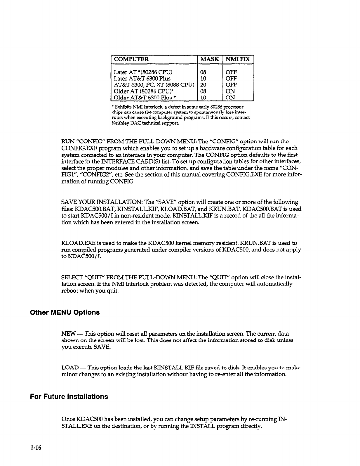
1 COMPUTER IMASK INMIFIX]
* Exhibits NMI Interlock, a defect in some early 80286 processor
chips can cause the computer system to spontaneously lose interrupts when executing background programs. If this occurs, contact
Keithley DAC technical support.
RUN “CONFIG” FROM THE FULL-DOWN MENU: The “CONFIG” option will run the
CONFIG.EXE program which enables you to set up a hardware configuration table for each
system connected to an interface in your computer. The CONFIG option defaults to the first
interface in the INTERFACE CARD(S) list. To set up configuration tables for other interfaces,
select the proper modules and other information, and save the table under the name “CONFIGl”, “CONFIG2”, etc. See the section of this manual covering CONFIG.EXE for more information of running CONFIG.
SAVE YOUR INSTALLATION: The “SAVE” option will create one or more of the following
files: KDAC500.BAT, KINSTALLKIF, KLOAD.BAT, and KRUN.BAT. KDAC500.BAT is used
to start KDAC500/1 in non-resident mode. KINSTALLKIF is a record of the all the information which has been entered in the installation screen.
KLOAD.EXE is used to make the KDAC500 kernel memory resident. KRUN.BAT is used to
run compiled programs generated under compiler versions of KDAC500, and does not apply
to KDAC500/1.
SELECT “QUIT” FROM THE PULL-DOWN MENU The “QUIT” option will close the instal-
lation screen. If the NMI interlock problem was detected, the computer will automatically
reboot when you quit.
Other MENU Options
NEW - This option will reset all parameters on the installation screen. The current data
shown on the screen will be lost. This does not affect the information stored to disk unless
you execute SAVE.
LOAD - This option loads the last KINSTALLKIF file saved to disk. It enables you to make
minor changes to an existing installation without having to re-enter all the information.
For Future Installations
1-16
Once KDAC500 has been installed, you can change setup parameters by re-running IN-
STALL.EXE on the destination, or by
running the INSTALL program directly.
Page 29

The syntax for the INSTALL command is:
INSTALL 1 -f I [ -mono I [ -rtm<display_area><wfs_200_address> ]
Any or all the modifiers may be used.
Details on the INSTALL command line modifiers are as follows:
-f
-mono
-RTM
The “-f” modifier tells KINSTALL to automatically load and use the set-up
information in the KINSTALLKIF file, rather than rechecking the system.
This option will permit you to modify parts of an installation without having
to re-enter all the information..
The “-mono” modifier selects monochrome output. Normally, the program
is able to sense what type of display adaptor the computer has and adjust the
display accordingly. Where a composite monochrome monitor is being
driven by a CGA, the color pallet is translated into various shades and patterns which may be unreadable under some circumstances. In these cases the
-mono modifier overrides the sensing of a display adaptor and improves the
readability of the screen.
The “-RTM” modifier can be used to specify all the set up information for the
RTM (Dataq WFS-ZOO) waveform scroller card. The full syntax for the RTM
modifier is:
-rtmcdisplay_area><wfs-ZOO_address>
There are four possible values for the display area:
LL = 400 pixels horizontal x 200 pixels vertical
HL = 640 pixels horizontal x 200 pixels vertical
LH = 400 pixels horizontal x 350 pixels vertical
HH = 640 pixels horizontal x 350 pixels vertical
The KINSTALL.KIF File
When you write an installation to disk with SAVE, a file named “KINSTALL.KIF” is also
written to disk. This file is a record of the information entered in the installation screen. This
information is valuable when you contact the applications department for help.
When operating on a CGA the only valid display area specification is HL.
When no display area is specified a default of HI-I (for EGA or MONO) is
used.
The scroller card address is a number from 0 to 3f8 (hex) which must be
evenly divisible by 8. The default address is 308.
NOTE: in order to specify an alternate address, a display area must also be
specified.
1-17
Page 30

Installations Involving the 500GPIB Module
If your system includes a 5OOGPIB module, note that KDAC500 does not perform installation
steps for this module. The 500GPIB driver installation is outlined in the 500GPIB manual. It
requires that the user manually edit the DOS AUTOEXEC.BAT file to insert the required
command line.
If You Have Problems Installing KDACSOO
If you experience any problems with INSTALL, first review your work. If you must call
Keithley DAC for assistance, have available a printout of your KDAC500.BAT file
(KDAC500/1 only) and KINSTALLKIF (if they exist).
You should also have available the make and model of your computer and type of monitor
adapter. Also print out copies of your AUTOEXEC.BAT file and CONBIG.SYS file. If possible,
be near your computer so that you can supply additional information if it is requested.
l-18
Page 31

Running the CONFIG Program
This section of the KDAC500 manual covers the creation of hardware configuration table
“CONFIG.TBL” with the KDAC500 program “CONFIG.EXE”. The following paragraphs discuss the purpose of the “CONFIG.TBL” file, explain the important run-time features of CON-
FIG, and provide a tutorial session using CONF’IG.
The Function of CONFIG.TBL
Keithley data acquisition and control systems are modular and expandable. The possible
combinations of modules, ranges, gains, and I/O configurations are practically unlimited.
KDAC500 must know the module names, switch settings, and related information in order to
control the hardware and acquire data. During installation, the INSTALL program can create
up to four configuration table filenames
system. These names are CONFIG.TBL, CONFIGl.TBL,...CONFIG4.TBL. You must run CONFIG to create a configuration table file for each of the file names.
Setting Up Channel Information (IONAMEs)
-- one for each interface card located in the computer
The CONFIG.TBL file must also include the channel information for each channel accessed by
KDAC500. This information establishes a name for a channel, as well as the slot, channel
number, gain, and other parameters needed to fully describe the channel for input or output,
hence the term “IONAME”. KDAC500 itself does not provide for an IONAME command to
be used within the programming environment.
An important function of IONAMEs in the CONFIG.TBL file is that they set programmable
functions in many modules which otherwise lack hardware switches. An important example
is the programmable local gain on the AMMlA and AMM2 modules. In this case, IONAME
enables you to set the both local gain and global gain for any channel input of the AMM module.
Menu Screens, Cursor Control, and Special Function Keys
All the functions of CONFIG are performed menu-style using tabular screens and the computer’s cursor and special function keys. The screens are “HARDWARE SETUP” and
“CHANNEL SETUP” (see figures 1-3 and figure l-4). Each screen contains several columns
or windows which show instructions and menu choices for configuration.
Selections are made with various special function keys Fl-FlO. Each key controls one or more
functions depending on which screen or window is active. Some keys are not used.
The cursor appears as flashing text in reverse video block. Cursor keys on the right side of the
keyboard control the movement of the cursor around the screen. The left and right arrow
1-19
Page 32

keys function only where choices are arranged in two or more columns. The up arrow and
down arrow keys control vertical movement, and will automatically move the cursor through
multiple columns.
==========================
HARDWARE SETUP ===I============~~========
AMM2: 16SE/8DI than analog in, 16 bit A/D, global mux. Slot 1 only.
SLOT
--
CARD SWITCH CONFIGURATION
AMM2
1
TRGl
2
NONE
3
AOM5
4
DIOl Port : A) IN B) IN C)OUT D)OUT
5
Range: lO.B, Filt: 100 KHZ, SING
Default Range: -10. to 10.V
6 EXT
MODULES
auto AIM6 AOM3
ADMl AIM7 AOM4 PIMl
ADM2 AIM8 AOM5 PIM2
AIM1 AIM9 DIM1 PROT
AIM2 AMMl DIOl STPl
AIM3 AMM2 DOMl STP2
AIM4 AOMl GPIB TRGl
AIM5 AOM2 PCMl NONE
FZ-FILE F3-MODULE
F9-LIST
Wed Jul 5 13:39
FlO-EXIT TO DOS
Path: D:\KDAC500\
F4-SWITCHES F5-CHANNELS
Figure 1-3 Hardware Setup
PCM2
l-20
==========================
CHANNEL SETUP
ANALOG1 : AMMZ, SL 1, CH 0, 16 BIT,
, A FP 7.2
SLOT CHANNEL
PORT IONAMES CHANNEL SETUP
1 0 8 ANALOG1
2 19
3 2 10
4 3 11
5 4 12
6 5 13
6 14
7 15
I
F2-SLOT
F3-CHAN/PORT
F4-IONAME
FlO-RETURN
Wed Jul 5 13:40 Path: D:\KDACSOOj
Figure Z-4. Channel Setup
==============I===========
LOCxl, GLOxl
1) ADD IONAME
8) RESISTOR
2) COPY IONAME 9) FILTER
3) DELETE IONAME
4) RENAME IONAME
5) ACCURACY
6) LOCAL GAIN
10) OFFSET
11) MODE/RANGE
12) CONVERSION
13) DISPLAY FORMAT
7) GLOBAL GAIN
FS-CHANNELS
Page 33

Special Considerations for the Model 575 and System 570
The CONFIG program contains an option which automaticahy creates a configuration table
for the Model 575-1, Model 575-2, or System 570. This configuration table contains the factory
default module assignments, ranges, gains, and other setup information for these systems.
To automatically create a Model 575-l configuration table, type:
CONFIG 575-l
To automatically create a Model 575-2 configuration table, type:
CONFIG 575-2
To automatically create a System 570 configuration table, type:
CONFIG 570
Press <Enter>. CONFIG loads a default configuration table. Refer to the specific hardware
manual for more details on setting up the system hardware.
The modules in the Model 575 and System 570 cannot be changed, except for the option slot.
However, you can change hardware switches (if present), and other set-up information for
the virtual slots. If you add an option module or change the hardware configuration, run
CONFIG and update the configuration table to show these changes.
The CONFIG commands shown above should be run only once to create the desired configuration table. Make subsequent changes to the table by running CONFIG. Then LOAD CONFIG.TBL, or the appropriate configuration table.
Running A Sample Configuration Session
The following instructions are a step-by-step tutorial through a typical configuration of
AMM2, AlM3, and DIOl modules installed in a 500A System. This exercise does not cover all
possible menu selections, and may not cover the particular hardware installed in your system. However, it will provide enough familiarity with CONFIG that you can create any configuration table that you will need.
This tutorial has five objectives:
1. Set up an AMM2 module in slot 1 with single-ended input, and +lOV A/D range.
2. Set up an AIM3 module in slot 6 with 16 differential inputs and a hardware gain of x100.
3. Set up a DIOl in slot 8 with channels O-15 configured as outputs and channels 1631 configured as inputs.
4. Create several IONAMES within the configuration table, including a digital output
IONAME for the DIOl port A and a digital input IONAMX for channel 31.
1-21
Page 34

This exercise will create a configuration table starting with a blank table, as is normally done
for a 500A.
Assigning Modules to Slots
To begin a practice session
KDAC500 Working Disk or fixed disk. From the DOS prompt, type:
CONFIG <Enter>
CONFIG will run and present the HARDWARE SETUP screen without any modules.
1. The cursor should be over 1 in the SLOT column. If necessary, use the cursor keys to
move the cursor to 1.
2. Press the special function F3 key to SELECT MODULE. The cursor will move to the
MODULES window.
3. Use the cursor keys to move the cursor over AMM2.
4. Press <Enter>. The cursor moves back to 1 in the SLOT column.
5. Move the cursor to the 6 position in the SLOT column.
6. Press F3 to SELECT MODULE. The cursor moves to the MODULES window.
7. Use the cursor keys to move the cursor over AIM3.
8. Press <Enter>. The cursor moves back to 6 in the SLOT column.
9. Move the cursor to the 8 position in the SLOT column.
10. Press F3 to SELECT MODULE. The cursor moves to the MODULES window.
11. Use the cursor keys to move the cursor over DIOl.
12. Press <Enter>. The cursor moves back to 8 in the SLOT column.
This completes the selection of modules for the configuration table.
running CONFIG, make sure you have booted the system from a
Setting Configuration Switches and Options
The following instructions describe the entry of switch information for the modules already
entered into the configuration table.
1. This step begins the assignment of the flOV A/D range for the AMM2 analog inputs. The
cursor should be over 1 in the SLOT column. If necessary move the cursor to 1.
2. Press special function key F4 to SET SWITCHES. GAIN information replaces the MODULES window.
3. Use the cursor keys to move through the available range settings to -10. to +lO.V. The
Ah4M2 module is software-programmable for gain and range, so there are no hardware
switches to be set. Gain is set in the IONAME commands.
4. Press <Enter>. The filter selection window will appear. Move the cursor to 1OOkHz.
5. Press <Enter>. The SINGLE-ENDED/DIFFERENTIAL choices appear. Use the cursor
keys to toggle the cursor to SINGLE-ENDED.
6. Press <Enter>. This concludes setting for AMMZ.
7. This step begins the setting of switches on the AIM3. Configuration of the AIM3A module is similar. Move the cursor to the 6 position in the SLOT column.
l-22
Page 35

8. Press special function key F4 to SET SWITCHES. GAIN information replaces the MODULES window. Switch setting information appears in the AIM3 manual.
9. Use cursor keys to move through the available gain settings to x 100. Set the gain
switches on the AIM3 according to the switch information at the top of the screen.
10. Press <Enter>. The SINGLE-ENDED/DIFFERENTIAL choices appear in the GAIN window. Use the cursor keys to toggle the cursor to DIFFERENTIAL. Set the input mode
switches on the AIM3 for differential operation (both switches up).
11. Press <Enter>. The window shows a choice between AIM3 and AIM3A. Move the cursor
to AIM3 and press <Enter>. This concludes set-up of the AIM3 switches.
12. This step begins the setting of switches on the DIOl. Move the cursor to the 8 position in
the SLOT column.
13. Press F4 to SET SWITCHES. PORT information replaces the MODULES window. (A port
is 8 input or output channels.)
14. The cursor will rest on either INPUT or OUTPUT according to the present setting for port
A. The port or channel being affected is listed at the top of the PORT window. Use the
cursor keys to toggle to OUTPUT, and then press <Enter>.
15. Repeat step 17 to set port B to OUTPUT. Repeat step 17, except with the cursor on “INPUT”, for ports C and D. After you configure the last port, the cursor will move back to 8
in the SLOT column.
The DIOl has a 4-bank DIP switch which is labeled “IN” and “OUT”. Set the DIP switches
for channels O-15 to “OUT”, and channels 16-31 to “IN”. This information is not repeated at
the top of the screen. The DIOlA module is software-programmable for I/O and does not
have switches.
This concludes switch settings for the system.
Programming IONAMES as Part of the Configuration Table
The next instructions explain how to program IONAMEs directly in the configuration table.
KDAC500 does not provide for an IONAME statement, so all channel information must be
set up through CONFIG.
Three IONAME’s will be set up:
l One IONAME for channel 2 of the AIM3 in slot 6 with differential input and global gain
(GA%) of 10.
l One IONAME for DIOl port A. KDAC500 will program these 8 lines for output as individ-
ual bits in a byte.
l One IONAME for the individual DIOl input channel 31.
During this operation, new options will appear in the CHANNEL SETUP window. These options deserve special note since some of their functions are not immediately obvious.
ADD IONAME - adds an IONAME for a slot/channel. Make sure the cursor is on ADD
IONAME. Press <Enter>. CONFIG prompts for the new IONAME. Type the name and press
<Enter>.
l-23
Page 36

COPY IONAME - copies the contents of an existing IONAME to the IONAME which is
highlighted in the IONAME column. To select an IONAME for copying, press F4-SELECT
IONAME. Move the cursor to the desired IONAME. Press F5-CHANNEL SETUP to return to
the CHANNEL SETUP window. Move the cursor to COPY IONAME and press <Enter>.
CONFIG will prompt for the IONAME to be copied to the highlighted IONAME. Type the
name and press <Enter>.
DELETE IONAME - deletes the IONAME highlighted in the IONAME column. To select an
IONAME for deletion, press F4SELECT IONAME. Move cursor to the desired IONAME.
Press F5-CHANNEL SETUP to return to the CHANNEL SETUP window. Move the cursor to
DELETE IONAME and press <Enter>. CONFIG will prompt for a confirmation before it deletes the selected IONAME.
RENAME IONAME - renames the IONAME highlighted in the IONAME column. To select
an IONAME for renaming, press F4-SELECT IONAME. Move cursor to the desired
IONAME. Press F5-CHANNEL SETUP to return to the CHANNEL SETUP window. Move
the cursor to RENAME IONAME and press <Enter>. CONEIG will prompt for the new name.
Type the name and press <Enter>.
ACCURACY - specifies A/D resolution - 1214, or 16 bits. Move the cursor to ACCURACY
and press <Enter>. Toggle to 12,14, or 16 with the cursor keys and press <Enter>.
LOCAL GAIN - specifies hardware gain selected for analog input modules which have onboard gain amplifiers. For gains which are set by hardware switches, CONFIG reads the
switch information you previously entered and updates LOCAL GAIN automatically. For
modules with software-programmable gain, LOCAL GAIN shows legal gain values. Move
the cursor to LOCAL GAIN and press <Enter>. Move the cursor to the desired gain and press
<Enter>.
GLOBAL GAIN - Gain applied by the master analog module global gain amplifier, but programmed on a slot-and-channel basis for any analog input modules. Legal values are xl, x2,
x5, and x10. Move the cursor to GLOBAL GAIN and press <Enter>. Move the cursor to the
desired gain and press <Enter>.
RESISTOR - The value of a resistor which you have installed on an analog input module for
current-to-voltage conversion. Move the cursor to RESISTOR and press <Enter>. CONFIG
will prompt for the resistor value in ohms. Type in the value (integer) and press <Enter>.
FILTER - For modules with software-programmable filters. Move the cursor to FILTER and
press <Enter>. Move the cursor to the desired filter and press <Enter>.
OFFSET - Enables or disables adjustable input offset feature of the AIM8. Move the cursor
to OFFSET and press <Enter>. Move the cursor to ENABLED or DISABLED as desired, and
press <Enter>.
l-24
MODE/RANGE - This menu selection set the mode of the PIM2 as either READ only, or
READ and RESET. This will either allow totalizing or not, depending on your application.
This command also sets the range of the AOM5 module.
Page 37

CONVERSION - In general, this function allows you to define the type of conversion that
should be performed on the input signal. It currently does not cause the conversion to take
place but can be used for documentation of the type of signal or tranducer that you are using.
For AIM8 and AIM9 you can set the calibration factor and calibration measurement units
used to calibrate the card and transducer. Move cursor to CONVERSION and press <Enter>.
Then move to SPECIAL and press <Enter>. Then select either LVDT/RVDT or STRAIN
GAGE. CONFIG then prompts for the calibration factor in millivolts per volt excitation. Type
in factor to three decimal places and press <Enter>. CONFIG prompts for calibrating units of
measure. Type in units (integer) and press <Enter>.
DISPLAY FORMAT - This function does nothing for KDAC500. It will be used in future
products to allow you to define the data formats for hard copy printouts of data, and for communication with analysis packages.
NOTE: The AIM6 module is supported in a different fashion from previous versions of CONFIG. To select the proper mode of operation for the AIM6, simply use the LOCAL gain menu
selection.
1. Before continuing, make sure the cursor is in the SLOT column of the initial HARD-
WARE SETUP screen. Press Esc several times if necessary to return to the HARDWARE
SETUP screen.
2. Use the cursor keys to move the cursor over 6 in the SLOT column. Press special function
key F5 for the CHANNEL SETUP screen.
3. Press F3 to SELECT CHAN/PORT. The cursor will move to 0 in the CHANNEL column.
4. Use the cursor keys to move the cursor to 2 in the CHANNEL column.
5. Press <Enter>. The cursor will move to ADD IONAME in the CHANNEL SETUP window.
6. Press <Enter>. CONFIG will prompt for an IONAME. This name can contain up to 8 letters and numbers. In this case, type in ‘TEST” and press <Enter>.
7. Move the cursor to ACCURACY in the CHANNEL SETUP window.
8. Press <Enter>. A/D menu choices appear in the CHANNEL SETUP window. Use the
cursor keys to select 16 BIT and press <Enter>. The CHANNEL SETUP choices will reappear.
9. Use the cursor keys to move the cursor to GLOBAL GAIN.
10. Press <Enter>. Global Gain choices will appear in the CHANNEL SETUP window. Use
the cursor keys to move the cursor to the x10 position. Press <Enter>.
11. This completes the configuration of IONAME parameters for the AIM3 module. Go directly to creating an IONAME for another slot by pressing F2 for SELECT SLOT.
12. The following instructions set up IONAME’s for the DIOl module port A and Channel
15. Use the cursor keys to move the cursor to 8 in the SLOT column.
13. Press F3 for SELECT CHAN/PORT. The cursor will move to the C
HANNEL column.
Press F3 again to move to the PORT column.
14. Use the cursor keys to move the cursor to A in the PORT column.
15. Press <Enter>. The cursor will move to ADD IONAME in the CHANNEL SETUP column.
16. Press <Enter>. CONFIG will prompt for an IONAME. In this case, type in “OUTA” and
press <Enter>. (The only parameter you can enter for digital I/O is the name.)
17. Press F3 for SELECT CHAN/PORT. The cursor will return to the PORT column.
18. Press F3 for SELECT CHAN/PORT again. The cursor will move to the CHANNEL column.
19. Use the cursor keys to move the cursor to 31.
20. Press <Enter>. The cursor moves to ADD IONAME in the CHANNEL SETUP column.
21. Press <Enter>. CONFIG will prompt for an IONAME. In this case, type in “IN15” and
press <Enter>. (The only parameter you can enter for digital I/O is the name.)
1-25
Page 38

22. This completes the assignment of IONAMES for the DIOl. Press F10 to return to the
HARDWARE SETUP screen.
File I/O
- Saving the Configuration Table
These steps will save the configuration table to disk.
1. Press F2 for FILE operations. The MODULE window will be replaced by a FILE I/O
menu. It includes choices for loading, saving, and deleting files, and for changing default
drives and directory.
2. Use the cursor keys to move the cursor to SAVE FILE.
3. Press <Enter>. The FILE I/O window will show the drive, directory, and one or more
configuration file names. If no CONFIG filename exist, only “new file“ will be shown.
Use the cursor keys to move the cursor to CONFIG or “new file”.
4. Press <Enter>. If you indicated “new file”, you will be prompted for a filename. If so, enter “CONFIG”. The file will be saved as CONFIG.TBL. The filename extension “.TBL” is
added automatically.
To save the table under another existing filename, move the cursor to that filename in place of
“CONFIG”. If there are more filenames than will fit in the window, press the cursor control
PgUp or PgDn keys to call up the additional filenames. Move the cursor to the desired filename and press <Enter>.
To specify a completely new filename, select the “new file” menu option. CONFIG will
prompt for a filename prefix, up to 8 characters. These characters must be legal DOS filename
characters. Enter only the filename prefix. Do not enter ,“TBL”.
File I/O
1-26
This concludes a typical configuration.
- Loading a Configuration File
These instructions presume that CONFIG.EXE is running, and that you want to modify a configuration table which resides on the disk. The desired file can be called back into the configuration table selecting the LOAD FILE option under F2-FILE.
1. Press F2 for FILE I/O. The MODULES window will be replaced by the FILE I/O.
2. Use the cursor keys to move the cursor to LOAD FILE.
3. Press <Enter>. The FILE I/O window will show the drive, directory, and one or more
configuration file names. Use the cursor keys to move the cursor to the desired filename.
In this case select “CONFIG”. If there are more filenames that will first in the window,
press the cursor control PgUp or PgDn keys to call up the additional filenames. Move the
cursor to the desired filename.
4. Press <Enter>. The file will be loaded into the CONFIG program workspace. Make whatever changes you desire.
5. To preserve the changes refer to the instructions above for saving a configuration table
file. You can save the configuration table under the name CONFIG, or its original name,
or as a new name.
Page 39

The configuration file thus loaded into memory will overwrite any configuration table that
may currently be in memory.
File I/O - Deleting a Configuration Table
These steps will delete a configuration file from the disk.
1. Press F2 for FILE operations. The MODULE window will be replaced by the FILE I/O
menu.
2. Use the cursor keys to move the cursor to DELETE FILE and press <Enter>.
3. CONFIG will list the configuration table file in the FILE I/O window. Move the cursor to
the filename to be deleted. If there are more filenames than will fit in the window, press
the cursor control PgUp or PgDn keys to call up the additional filenames. Move the cursor to the desired filename.
4. Press <Enter>. CONFIG will prompt for a confirmation. Type ‘Y” and press <Enter>.
File l/O - Changing the Default Drive or Directory
1. Press F2 for FILE I/O.
2. To change the default drive, select CHANGE DRIVE from the FILE I/O window and
press <Enter>. CONFIG will prompt for the drive ID. Type only the letter of the drive (no
colon) and press <Enter>.
3. To select a different directory, select CHANGE DIRECTORY from the FILE I/O window
and press <Enter>. CONFIG will prompt for the directory name. Type an existing DOS
directory name and press <Enter>.
If the new directory name is on the current default drive, subsequent disk I/O will address
that directory. If the directory is on a drive other than the current directory drive, you must
also CHANGE DRIVE to make the new drive the default. Attempting a change to a nonexistent drive or directory will produce an error message.
Generating a Configuration Table File Report
CONF’IG can generate a report of the configuration table and IONAME’s. The report can be
listed to the screen, written to a disk file, or sent to the printer.
1. Press F9 to LIST. The MODULES window changes to show the output destinations FILE,
PRINTER, or SCREEN.
2. Use the cursor key to select the desired destination for the report and press <Enter>. If
you select SCREEN, CONFIG will show a summary report of the configuration and
IONAMES. Press any key to return to the FILE, PRINTER, or SCREEN menu. If you select FILE, CONFIG will prompt for the filename. Type a legal DOS filename and press
<Enter>. The filename will overwrite any existing file with the same name. If you select
PRINTER, CONFIG wiIl prompt for confirmation that the printer is ready. Be sure that
the printer is connected and turned on. Type ‘Y” and press <Enter>.
3. Press Esc to return to the HARDWARE SETUP screen.
1-27
Page 40

Leaving the Config Program
1. If necessary, press Esc several times or cFlO> to return to the HARDWARE SETUP
screen.
2. Press cFlO> to exit. The program will remind you to save the changes. If you have saved
them and want to end CONFIG, enter “Y” and press <Enter>. If you need to save the
configuration table and haven’t done so, press “N” and <Enter>. CONFIG will move di-
rectly to the SAVE menu. Save the table using the F2-FILE instructions before leaving
CONFIG.
Aborting a Configuration Session
You may abort a configuration session by repeatedly pressing the escape (“Esc”) key until the
HARDWARE SETUP screen reappears. Then, press cFlO> to exit to DOS and answer the
prompt ‘9” for Yes. If you do not save the configuration table, all configuration files stored
on the disk will remain unchanged, and any changes made to the configuration table in memory will be lost.
You may also abort a CONFIG session from anywhere in CONFIG by pressing <AltxFlO>.
No prompt will be given for exit verification.
1-28
Page 41

Methods of Creating a KDACSOO
Program
Before you begin with KDAC500, you should become completely familiar with the programming language package you have chosen and how to write, debug, and compile a program.
The KDAC500 documentation does not replace the compiler reference manual.
There are quite a few ways of creating and running KDAC500 programs. The following paragraphs describe these methods. In each case it is assumed that access to the interface routines
is available. Before the K5OO.EXE kernel is loaded, KDAC500 programs can be compiled but
cannot be run.
General
Method for Creating Executable Test Programs
If you have experience in using Keithley’s Soft500, Quick500, or KDAC500/1 software, you
will note some major changes in how you approach programming with KDAC500/B and
KDAC500/M. The most important of these is that, under KDAC500/B and /M, you may not
be able to run and debug your program from within the compiler’s editor/environment (provided it has one). For example, Soft500 and KDAC500/1 programs are written, run, and debugged entirely from within the BASIC interpreter environment.
In contrast, KDAC500/B and KDAC500/M operate with several compilers. The memory requirements of these compilers leave very little free memory for arrays. Therefore, it is more
realistic to create your program source code with a text editor, and then compile the program
from the DOS prompt. Note that the QuickBASIC, Quick C, Microsoft C, and Borland Turbo
compilers have an editor/environment which enables you to write and edit source programs
and then proceed directly to the compile/link step. These environments automate many of
the steps which must be completed manually when compiling from the DOS prompt.
A second consideration for KDAC500 programmin
your test program before you begin
put and output channels, and then
in the hardware configuration table. You will also need to identify the amount of data that
will be generated when the program runs. While some packages permit programming “on
the fly”, KDAC500 requires a more organized approach. In the long run, this approach will
result in better, more easily maintained test programs.
programmin g.
running CONFIG.EXE to set up the necessary IONAMEs
g is that you must have a clear design for
This includes identifying the various in-
The general approach to creating executable files with KDAC500/B and KDAC500/M is as
follows:
3.
Install your compiler and the KDAC500 software on your computer system. Confirm that
the compiler can “find” any header or library files, and that it runs properly before you
attempt to write a KDAC500 programs.
4.
Design your test program.
5.
Run the KDAC500 CONFTG.EXE program to create the necessary hardware configuration
table for your DAC hardware. Decide on the channels of input and output, and set this
l-29
Page 42

information up as IONAME data in the table. Note that there is no provision for setting
up IONAMEs directly within your test programs.
6. Run the compiler’s editor/environment and write or edit your program source code.
Note that you must “include” the appropriate KDAC500 langauge support file in your
program: KDAC500.BI for QuickBASIC programs, KDAC500.H for Microsoft C, Quick C,
and Borland Turbo C, “include ‘KDAC500.FI’ fl and “include ‘KDAC500.FD’ ” for
Microsoft FORTRAN, and the statement “uses KDAC500” for Borland Turbo Pascal.
7. Compile, link, etc. to produce an executable file. You can usually do this most conveniently from within the compiler environment. Most environments will aid in the debugging process by identifying compile or link errors. You can normally compile and link
from the DOS command line as well, but without some of the benefits of the environment
(see your compiler manual for the correct DOS command line syntax and other procedural details).
8. Run the successfully compiled program with the KDACSOO “KRUN” utilities. See the
next section ‘Methods of Running a KDAC500 Progam” for details.
9. Test the various program functions to make sure it does what you expect.
10. Repeat 48 until the program functions as desired.
QuickBASIC Programming
OBJECTIVE: Run the QuickBASIC editor/enviroment and create an executable (.EXE) pro-
gram.
gram and a Quick Library all resident in memory at the same time, so it isn’t feasible to run
KDAC500 programs from within the QuickBASIC environment. However, the environment
is an excellent place for editing, debugging, and compiling your KDAC500 programs.
Generally speaking there is not enough RAM left with QuickBASIC, K500, your pro-
METHOD: First you must create a Quick Library that QuickBASIC can use. The library file
KDAC5OO.LIB is the file that will be used to make it. This need only be done one time. Once
the Quick Library has been created it can be used for all your QuickBASIC programs.
At the DOS prompt type:
link /QU KDAC500.LIB,,nul,BQLB45<enter>
The file BQLB45 is a library file that is supplied with version 4.5 of QuickBASIC.
create Quick libraries for version 4.5 of QuickBASIC. Refer to the section on Quick Libraries
in the QuickBASIC manual for more information.
Next, start QuickBASIC and load the KDAC500 Quick Library.
At the DOS prompt type:
qb /1 KDAC5OOcenter>
Write and edit your program using QuickBASIC’s smart editor and syntax checker. The interfaces to the KDAC500 library are defined in the file KDAC500.BI which must be included
in your QuickBasic program with the statement:
It is used to
l-30
Page 43

‘$INCLUDE: ‘KDAC500.BI’.
When the program is satisfactory, use the QuickBASIC “ALT .R” command to access the
“RUN” pull-down menu.
Select the “Make EXE” option and complete the remaining QuickBASIC steps to produce a
compiled test program file on disk.
QuickBASIC started, QuickBASIC “knows” to look for the KDAC500.LIB file automatically
when it creates the .EXE file. Leave QuickBASIC and execute the program with the KDAC500
“KRW utility; e.g. “KRUN <your program>“.
C Programming
OBJECTIVE: Run the Turbo C or QuickC editor/environment and create an executable program. As with QuickBASIC, there is not enough RAM to execute your KDAC500 program
from within the environment. However, the benefits of the environment’s debugging and
editing facilities outweigh the drawbacks.
METHOD: First a file that defines the modules that make up your program must be created.
In Turbo C this is called a project file. In QuickC it is called a program list. You can use the
Turbo C editor to create a project file for your program.
program lists. Let’s assume that our program is named TEST1.C.
Because the KDAC500 Quick Library was loaded when
QuickC has a facility for creating
The project file for TESTl.EXE (Turbo C) will contain two lines:
TEST1 .C
TLJRBO5OO.LIB
If TESTl.EXE was made of multiple modules each module would be entered into the project
file. See the Turbo C documentation for more information on project files. The important
thing to remember about project files used to create KDAC500 programs is the inclusion of
the TTJRBO5OO.LIB line.
ences to KDAC500 functions. The interfaces to KDAC500 library are defined in the
KDAC500.H header file. This file must be included at the top of your program with any other
include’s that are needed.
The program list for TESTl.EXE (QuickC) will contain these two files:
TEST1 .C
KDAC5OO.LIB
If TESTl.EXE was made of multiple modules each module would be entered into the pro-
gram list. See the QuickC documentation for more information on program lists. The important thing to remember about program lists used to create KDAC500 programs is the inclusion of KDAC500.LIB.
ences to KDAC500 functions.
If it is not present, Turbo C does not know how to resolve the refer-
If it is not present, QuickC does not know how to resolve the refer-
1-31
Page 44

Complete the remaining steps to produce a compiled program on disk. Refer to the documentation for your compiler. The completed.EXE file can be executed from the DOS command line using the KDAC500 “KRUN” utility, e.g. “KRUN <your program>“.
Pascal Programming
OBJECTIVE: Run the Turbo Pascal or Quick Pascal editor/environment and create an executable program.
program from within the environment.
METHOD: KDAC500 is very easy to implement with Turbo Pascal or Quick Pascal. The only
requirement is the one statement:
uses KDAC500;
This command must be included within your Pascal program if you wish to access the
KDAC500 functions. Standard Pascal Units can be used in conjunction with KDAC500 (i.e.
uses Crt, DOS, KDAC500;). Refer to the Turbo Pascal or Quick Pascal documentation for more
information on Pascal Units. Run the completed EXE file from the DOS comman
the KDAC500 “KRUN” utility, e.g. “RUN <your program9’.
As with QuickBASIC, there is not enough RAh4 to execute your KDAC500
d line with
FORTRAN Programming
OBJECTIVE: Create a program using the Microsoft FORTRAN 5.0 package.
METHOD: Creating an executable file using FORTRAN is quite easy. First, create the source
code with an ASCII-compatible word processor or notepad editor. The program must contain
the following lines at its beginning:
include ‘KDAC5OO.FI
include ‘KDAC5OO.FD
When the source code is complete, save it as an ASCII file. Compile the source by executing
the following command at the DOS prompt:
fl / c / AL&lename.ext>
The filename must be complete, including the filename extension. (The extension typically
used for FORTRAN program is “.FOR”).
l-32
Next, link the object module by executing the following command at the DOS prompt:
link &lename>,&lename>,nul,KDAC500
Page 45

Make Files
The first <filename> refers to the name of the .OBJ module created during the compile step.
The second <filename> refers to the name of the resulting .EXE file. Normally, both names
will be the same as the original FORTRAN source. The filename extensions are not used here.
Run the completed .EXE file from the DOS command line with the KDAC500 “KRT_JN” utility,
e.g. “KRLJN <your program>R.
OBJECTIVE: Create an executable program using a program build utility such as MAKE.
METHOD: The only requirement for using a MAKE utility is to be sure to Iink with the cor-
rect library or there wiII be unresolved references. The stand alone Turbo Pascal and Quick
Pascal compilers are exceptions to this ruIe because the “Uses KDAC500;” statement tells the
compiler what to use.
to use that makes Iinking as easy as with Pascal.
Unfortunately there is no way to teIl the other languages which library
You must specify the name of the library at
link time.
TEST1 .EXE : TEST1 .C
tee -c -ms test1 .c
tlink cOs+testl,testl,nuI,cs + turbo500
TEST1 EXE : TEST1 .C
qcl -c test1 .c
Iink testl,testl,nuI,KDAC500
TESTl.EXE : TESTl.BAS
bc testl;
link testl,testl,nuI,KDAC500
TEST1 .EXE : TEST1 PAS
tpc testl.pas
TEST1 .EXE : TEST1 PAS
qpl testlpas
TESTl.EXE : TESTl.FOR
FL/C/AL Testl.FOR
LINK TESTl, TESTl, NUL,KDAC500
; Turbo C example
; small memory model
; QuickC example
; QuickBASIC example
; Turbo Pascal example
; Quick Pascal example
; Microsoft FORTRAN example
1-33
Page 46

Methods of Running a KDACSOO
Program
Before you continue with this section, you must have installed KDAC500 and your compiler
on your computer, and also created a configuration table file for each data acquisition system
installed in the computer.
KDAC500 can be started and run in a number of different operating modes. To understand
these modes, it is important to note the functions of several files in the KDAC500 package.
KDAC500 FILES:
KDAC500,LIB - A library file which resolves the KDAC500 functions you include in a
KDAC500 program. KDAC500,LIB is the library of routines that is used with Microsoft C,
QuickC, QuickBASIC v4.x, and Microsoft FORTRAN 5.0. These statements communicate
with the data acquisition hardware. KDAC500.LIB must be on the disk and accessible when
you link your programs or error messages will result.
TURB0500.LIB - Same as KDAC500.LIB but used with Borland Turbo C 2.0
KDAC500.TPU - Same as KDAC500.LIB but used with Borland Turbo Pascal 6.0
KDAC500.T55 - Same as KDAC500.LIB but used with Borland Turbo Pascal 5.5
KDAC5OO.T50 - Same as KDAC500.LIB but used with Borland Turbo Pascal 5.0
KDAC500.QPU - Same as KDAC5OO.LIB but used with Microsoft Quick Pascal 1.0
K5OO.EXE - This is the memory-resident kernel which controls the data acquisition hardware. K500 must be in memory in order for you to run any KDAC500 programs. IUWN.BAT
and KLOAD.BAT load K500.EXE into memory (see KRlJN.BAT and KLOAD.BAT descriptions below). K500.EXE must be on the disk and accessible when you run KDAC500 pro-
grams
KRUN.BAT - KRUNBAT runs KDAC500 programs that have been compiled into DOS exe-
cutable form (EXE). KRUN will return to DOS when the program terminates. The KRUN file
loads the K500.EXE kernel into memory, and then runs thespecified KDAC500 program
(EXE file). KRLJN loads the KDAC500 KERNEL (K500.EXE) temporarily. Once the
KDAC500 program terminates, K500 removes itself from memory before returning to DOS.
The syntax for this command is:
KRUN <your program name> cargl> carg2>....
If there are any arguments to be appended to your program, enter them after the name of
your program.
1-35
Page 47

KLOAD.BAT - This batch file loads the K500.EXE kernel and makes the kernel permanently
resident in memory. After K500.EXE has been made memory resident, KLOAD will return to
DOS where you can nm your compiled programs by simply entering the program name at
the DOS prompt.
The syntax for this command is:
KLOAD
136
Page 48

Operating more than One Data
Acquisition System on a Single
Comwter
KDAC500 has the ability to run up to four data acquisition systems using one computer as a
host.
Set-up Procedure
You must adhere to the following setup procedure to operate more than one data acquisition
system on a single computer:
Each System Must Have its own Interface
Each data acquisition system must have its own interface plugged into the computer. (This
requires that the computer have enough expansion slots available.) The KDAC500 INSTALL
program will assign the first interface entered in the installation screen as the “master”. The
interrupts of the master interface card become the master interrupts and control the background data acquisition of all the interface cards. This is the case even though all of the interfaces are capable of generating interrupts for data acquisition.
Each Interface Must Have A Unique Address
Each interface you install must be set to a different address. Generally, the address ranges
CAF8OCFF80 and DOF80-DFF80 can be used successfully on both XT- and AT-class comput-
ers.
Each System Must Have A Separate Configuration Table File
For multiple acquisition systems, KDAC500 must have a method of accessing the specific
hardware in each system. This task is achieved by using a separate, unique configuration ta-
ble (“.TBL”) file for each interface. Accordingly, you must run CONFIG and create a hard-
ware configuration table file for each interface address. Each file must have a unique file
name. Normally, you should use the names provided for by the INSTALL program (CONFIG, CONFIGl, CONFIG2, CONFIG3).
Each configuration table file may be a duplicate of the others in terms of the hardware modules and placement within the slots. However, all IONAMEs which are set up within the
configuration table files must be different. No two tables may have duplicate IONAMEs. See
the section of
running the configuration program CONFIG for more information.
1-37
Page 49

The KDACBOO Installation Must Identify all the Interface Addresses and Config Filenames
If you have done an installation for one data acquisition system, and later want to add more
systems to one computer, you must do a re-installation with the addresses and the configuration table filenames for each interface plugged into the computer.
Running Multiple Systems
To run KDAC500 with multiple systems, start KDAC500 as you normally would with a single
system. Write your test program. Observe that the memory in the computer is now serving
multiple acquisition systems. You may have to adjust the number or size of the data arrays in
order to fit ah data into the available memory.
l-38
Page 50

Initializing Hardware at Power-up with
HARDINIT
(NOTE: This information describes how to set up the HARDINIT command. Please refer to
any other safety-related information concerning specific cards in your data acquisition system.)
KDACSOO includes a utility program “HARDINlT.EXE” which can initialize all the digital
and analog output modules to a known state when the system is booted.
When you turn on the data acquisition system, some output modules may power up in a
“scrambled” state. This condition would normally exist until you load and run a data acquisi-
tion program which initializes the hardware. By inserting HARDINIT with the necessary parameters into the AUTOEXEC.BAT file, system initialization will occur when the computer
boots and executes AUTOEXEC.BAT. This occurs when the computer is turned on, or when
you do a warm reboot (CTRL-ALT-DEL).
You must observe a few precautions when you use HARDINIT:
1.
The data acquisition system(s) must be turned on at the time the ATJTOEXEC.BAT file
with HARDINIT is executed. HARDINIT will not initialize hardware which is turned off.
2.
HARDINIT uses the configuration table files to identify and initialize output modules.
The configuration table filenames must include the drive letter and path corresponding to
their location on the fixed disk or floppy diskettes. Failure to do so will produce the error
message “Configuration file not found”, and the hardware will not be initialized.
3.
The KDAC500 utility HARDLNIT.EXE must be accessible to ALJT.OEXEC.BAT, either directly, or in the search path. Install copies HARDINIT.EXE to the working diskette or
fixed disk directory along with the rest of KDAC500. For a fixed disk, it is easiest to simply recopy HARDLNIT.EXE to the fixed disk root directory.
Format of the HARDINTT command:
HARDINJT -c OxAA&4 <CONFIG table filename> -p
Where:
-c specifies that the following parameter is an interface address and configuration filename.
OxA4AA is the address of the interface. AA&4 represents the four most significant digits of
the address in hexadecimal notation.
<filename> is the complete configuration table filename (with full path spec.) corresponding
to the interface at AAAA.
1-39
Page 51

-p is a “pause” option. Ending the HARDINIT command line with “-p” will type a reminder
to the screen that the data acquisition systems must be turned on. You will have to press the
<Enter> key before the initialization takes place.
The sequence “-c OxAAAA filename” must be entered for each data acquisition system that is
to be initialized. The -p option is used, it should be inserted at the end of the HARDINIT
command line and used only once per HARDlNlT command line.
An example of an ATJTOEXE.BAT containing one HARDINIT is as follows:
ECHO OFF
CLS
HARDINIT -c 0xAFF8 C:\K500\CONFIG.TBL -c OxCFF8 C:\K500\CONFIGl.TBL -p
DATE
This AUTOEXEC.BAT file will initialize two systems simultaneously: one at address AFF80
and one at address CFB80. It will also pause for a press of the <Enter> key.
An alternate technique for using HARDINIT is to enter a separate HARDINlT command for
each system. An example AUTOEXEC.BAT file containing two HARDINIT’s is as follows:
ECHO OFF
CLS
HARDINIT -c OxAFF8 C:\K500\CONFIG.TBL -p
HARDINIT -c OxCFF8 C:\K500\CONFIGlTBL -p
DATE
TIME
This ATJTOEXEC.BAT will initialize systems at address AFF80 and at address CFF80. The
systems will be initialized sequentially. HARDIN’IT will pause for a press of the <Enter> key
for each system.
l-40
Page 52

KDACSOO System Features
KDACSOO Memory Management
Background/Foreground
Triggering
Engineering Units Conversion
CHAPTER 2
Page 53

KDAC500 Memory Management
The KDAC500 Memory Management System provides an extremely flexible and sophisti-
cated memory management system which is well-suited for data acquisition and control ap-
plications.
Its main purposes are:
l To provide very large data arrays.
l To provide data structures with special features which make them particularly useful for
data acquisition and control applications.
l To free your program’s data space for your own applications.
l To allow you to implement two memory management systems at once (KDAC50O’s and
your compiler), each with its own advantages, and to be able to make the best use of each.
To understand the KDAC500 Memory Management System, a memory map is needed. The
following diagram represents the typical memory usage for IBM, Compaq, and MS-DOS Ver-
sions 3.0 or later.
The exact boundaries of the blocks containing the Disk Operating System, your program, and
K500.EXE may vary depending on their versions. The hardware shown in memory above
AOOO:OOOO will vary depending on the options installed in the computer.
When you install KDAC500, you must consider the information in the memory maps, includ-
ing the memory size of your computer. You must have a clear understanding of your ulti-
mate memory requirements when you run KDAC5OO’s INSTALL program. If you select too
large an array space, you will receive a variety of error messages from KDAC500, your appli-
cation, or both. Numbers for your system depend on the rev level and size of DOS, the size
the K500.EXE kernel, and any other memory-resident programs you may be running. These
are approximations, and should be verified for your particular hardware, software, and appli-
cation program.
The KDAC500 startup batch files KLOAD.BAT and KRUN.BAT contain a “-m” parameter
that specifies the amount of memory to be reserved for arrays. This parameter represents the
number of 16-byte memory segments that KDAC500 will have for data arrays. The KDAC500
INSTALL process sets the -m parameter according to your input at the time of installation.
The easiest way to alter the memory reserved for arrays is to rerun INSTALL. Alternately,
you can use an ASCII word processor or DOS’s EDLIN utility to modify the KLOAD or
KRUN batch files directly.
2-3
Page 54

MEMORY MAP - IBM XT or AT WITH 640K AND FIXED DISK
HEXADDRESS
(SEGMENT:OFFSET)
:FFFF
:EOOO
EOOO:
DOOO:
:FF80
cooo:
:8000
:oooo
BOOO:
AOOO:
9000:
8000:
7000:
6000:
5000:
ROM BIOS area
IBM BASIC-in-ROM
AT: 64K reserved memory area.
XT: available for IBIN (ExF80)
or E,MS memory (64K).’
Available for IBIN (DxF80)
or EMS memory (64K)!
AT: available for IBIN (CxF80).
XT: available for IBIN from
CAF80 to CFF80. ’
Color Adapter Memory
Mono Adapter Memory
Reserved for EGA (64K), but
available for IBIN (AxF80) if
no EGA is installed.1B2
User Program Memory.
Data array space as
specified during
_ K bytes:
1024K
. 960K
896K
832K
768K
704K
640K
576K
512K
--I
2-4
4000:
3000:
2000:
1000:
0000:
K500.EXE KERNEL
CLKSPD.COM (timina software)
Disk Operating Svstem 3
. _
_ _
I
._-. _
128K
1 64K
I -
’ OK
1. Any address in this block ending in “F80” can be chosen provided there
is no conflict with other hardware. Factory-suggested address for IBIN is CFF80.
2. ON IBM PC’s with 256K mother board, and on some compatible computers,
this space can also be populated with RAM to increase addressable system
RAM to 704K. (Not applicable for IBM Portable PC, XT, and AT, or systems
with EGA).
3. Varies in size depending on amount of RAM specified for array during
installation. A small portion of the DOS file COMMAND. COM resides
at the top of system RAM. It is not shown in this diagram.
Page 55

Table 2-1. Approximate Array Space for KDAC500/B and KDACZOO/M
Total System RAM Available
RAM
for Arravs
640K
576K
512K
How Data Arrays are Created for KDAC500
NOTE: The following programming commands and examples are shown in QuickBASIC format, as would be used with KDACSOO/M. Coding conventions and punctuation (such as single or double quotes, underscores, and periods), vary with from language to language. However, actual KDAC500 command names, general usage, and functionality are the same, regardless of KDAC500 version.
KDAC500 input commands (BGREAD & ANINQ) create KDAC500 arrays automatically
when they are executed. KDAC500 arrays can also be created with the KDAC500 command
ARMAKE (ARray MAKE).
For example, the statement:
call armake(“arrayl”, 1000, “ION1 ION2”)
-300K
-236K
-172K
creates an array named array1 with 1000 elements and a width of 2 elements. The IONAMXs
after the array depth determine the array type. If ION1 is an analog channel, each element
will occupy two bytes of RAM. The name given to the array enables other KDAC500 commands to access the array.
Using the array name, you may put values in the array, retrieve values from it, save/retrieve
the array to/from disk, and perform several other tasks on the array.
In the above example, the array type was determined by the IONAME. There are four types
of KDAC500 arrays:
BIT ARRAY - Packed bit arrays. Values stored as O’s and 1’s. Used with digital input and
output commands.
BYTE ARRAY - Elements of eight bits each. Values stored as unsigned bytes, 0 to 255.
Used especially with commands that access digital I/O ports.
INTEGER ARRAY - Elements two bytes long. Values stored as unsigned integers, 0 to
65535. Used especially with analog input and output commands.
LONG ARRAY - Elements four bytes long. Values stored as unsigned long integers, 0 to
4,294,967,295. Long arrays are used with the 32-bit pulse input commands.
2-5
Page 56

Every time you create a KDAC500 array, the array type is determined by the IONAME list.
This information tells KDAC500 how much memory should be allocated or accessed for each
data point in the array, as welI as the intended use for the array.
KDAC500 can retrieve any value stored in a KDAC500 array as raw binary (i.e A/D counts
for analog data) or engineering units. Even though values are stored as integers, they may be
returned as volts, milliamperes, degrees C, or other engineering units according to the module, transducer, and EUF parameter being used.
Aside from making arrays and accessing the data, KDAC500 provides many commands to
increase the usefulness of KDAC500 arrays. Arrays can be deleted (deallocated from RAM)
with the ARDEL command. A descriptive string may be associated with the array using ARLABEL, so that if it is saved to disk with ARSAVE, then loaded back into RAM with ARLOAD, any information in the string will remain associated with the array. ARSTATTJS will
return information to you regarding the array. ARLASTP will return the depth index of the
most recently (in real-time) sampled or output value in a KDAC500 array (see the command
reference section for more details).
Finally, KDAC500 graphics commands support KDAC500 arrays (GRAPH, GRAPHRT,
HGRAPHRT). In addition, these commands all support internal conversion to volts and engineering units.
2-6
Page 57

Background I Foreground
One of KDAC500’s most powerful features is its background/foreground processing. Background/foreground takes KDAC500 far beyond the abilities of simple programs, allowing
the Keithley data acquisition system to manage independent tasks at machine language
speeds - without machine-language programming.
The concept of KDAC50O’s background/foreground is easier to understand if one examines
the interface cards included with the Keithley data acquisition systems. The IBIN cards con-
tain interrupt-generating circuitry which works in conjunction with the computer’s interrupt
handling abilities. The KDAC500 function INTON (INTerrrupts ON), allows you to specify
the frequency with which you want interrupts to be generated. The command for generating
an interrupt every 100 milliseconds looks like this:
CALL INTON( 100, MIL)
When the INTON function is called, the programmable interval timers on the Keithley interface installed in the computer begin to generate interrupts at the specified interval. Each time
an interrupt occurs, the processor jumps from executing foreground tasks (your program or
foreground KDAC500 commands) to executing background tasks, Each background task is
checked to see if it requires handling on a given interrupt, and is executed appropriately.
When all the background tasks have been worked through, control is returned to the foreground until the next interrupt.
The background acquisition tasks should have the highest priority. The KDAC500 installation
program permits you to specify NMI, CLOCK, or IRQ 9,3, or 5 as the interrupt controlling
background acquisition. All the time-critical data acquisition and control tasks are thus han-
dled at regular intervals. In order to maximize accuracy, special care is taken by KDAC50O’s
background controller to assure that samples and updates are not time-skewed. Most nonbackground KDAC500 commands and all ordinary BASIC commands are classified as “fore-
ground” commands, and will be executed during free time when the system is not servicing
the interrupt-driven commands.
KDAC5OO’s background/foreground operation is a form of multitasking in that it allows the
computer to perform one high-priority task (background) and one low-priority task (fore-
ground) in a time-sharing fashion.
It is important to remember that although the foreground and the background appear to op-
erate simultaneously, the computer is really switching its attention back and forth between
two tasks. Foreground/background commands also operate independently. After a back-
ground command is issued, it is only possible for the foreground to know how the background commands are progressing through the use of various status commands.
Background/foreground processing gives the programmer considerable flexibility. While
data acquisition and control sequences execute in the background, the foreground can be
used to monitor the status of background tasks, to communicate with the operator or with
2-7
Page 58

other peripheral devices, or to perform analysis on previously collected data. In fact, it is possible to have the KDAC500 program set up data acquisition sequences in the background,
then terminate and pass control back to DOS. Depending on the speed of acquisition and the
amount of free RAM, you may be able to run other application programs while the background tasks continue. Later, another KDAC500 program can be run which harvests the data
from the arrays filled by the first program.
Foreground and Background Communication
So far, we have discussed one basic way that the foreground communicates with the background: setting up task sequences with KDAC500 background commands. There are a number of other ways that the foreground can act on and track the background’s operations.
To begin with, KDAC500 offers a background triggering capability. This feature is covered
thoroughly elsewhere in this manual. However, we will examine it briefly here in the general
context of background operation. As we have discussed, once background commands have
been started by the foreground, they can proceed independently of the controlling program.
Background triggering allows acquisition and control sequences to be started independently
of the foreground.
The KDAC500 command, TRIGGER, can act as a background trigger. This command allows
the background to react directly to real-world events such as digital inputs or threshold values on analog channels.
Background commands such as BGREAD or BGWRlTE can be linked to TRIGGER with a special parameter, the “trigger mode”. When KDAC500 encounters this parameter, the task is set
up in the background but not started. It remains latent until triggered, at which time the task
begins without foreground intervention.
One of the background’s most useful features is that once sequences are set up, they do not
require the attention of the controlling program. However, there are many instances when it
is useful for the foreground to be able to monitor ongoing background tasks. For example,
after acquiring data with BGREAD (BackGround READ), it is often desirable to save that data
to disk. However, before the foreground program can issue the ARSAVE command, it must
determine that the acquisition sequence is complete. Similarly, when alarm conditions are
detected, orderly shutdown procedures may need to know which sequences are active, and
which are waiting for triggers.
For situations like these, KDAC500 includes commands which allow the foreground to check
the progress of the background commands. In both of the above examples, the BGSTATLJS
command could be used to poll the background for the necessary information.
BGSTATUS assesses whether a background task is executing, waiting for a trigger, or finished. To facilitate this, all background commands have an optional parameter, the “back-
ground function name” (BFN) which allows tasks to be easily identified. A background task’s
parameter list should always include this parameter if it will be monitored from the fore-
ground.
2-8
Page 59

There are also situations where it is necessary to know exactly how much of a data array has
been filled or output, or it may be desirable to synchronize computations in the foreground
with acquisitions in the background. In both cases, ARLASTP (ARray LAST Point> can provide the necessary data.
ARLASTP returns the depth index of the last point in an array which has been accessed by a
KDAC5OO background command. Remember that each width is associated with a particular
channel, and that depth levels are associated with the number of samples acquired. ARLASTP is particularly useful when you wish to perform some analysis on part of an array,
while the rest of the array is still being acquired. It can be used in conjunction with ARGET
(ARray GET) to retrieve one or more of the most recently acquired data points for computation. In process control applications, ARLASTP and ARGET can be used to synchronize data
logging and the acquisition of data for control loops.
The foreground program can also act to stop, clear, and restart the background, as well as to
stop ongoing tasks selectively. INTON (INTerrupts ON) starts the background, and can be
issued either before or after background commands have been set up. This allows it to start
any number of tasks simultaneously so that they are synchronized. Similarly, LNTOFF
UNTerrupts OFF) stops the background, whether or not tasks are currently running. When
INTOFF is issued, no tasks are cleared, so that the background can be temporarily halted and
then restarted from the same place (note, however, that all timers are cleared by this proce-
dure).
If desired, the background can be cleared of all active and latent tasks with the BGCLEAR
(BackGround CLEAR) command. The BGHALT command can be used to stop and clear
background tasks selectively.
The Singleground Mode
Foreground/background processing is extremely useful for most measurement and control
tasks. In some circumstances, however, it may be preferable to operate in KDAC50O’s
singleground mode.
exception that background functions are not allowed. This allows KDAC500 to operate as
fast as possible.
INput Quick) and ANOUTQ (ANalog OUTput Quick) can only be achieved by suspending
background operation.
In particular, the very high speed sampling provided by ANINQ (ANalog
KDAC500’s Timers
Along with data acquisition and control functions, KDAC5OO’s timers also operate in the
background. Each time an interrupt occurs, all of the timers which are currently on will
“tick”. These timers require that the background be on in order to operate. If the background
is suspended (with INTOFF), updating of the software timers will stop and they will retain
their last values until they are restarted or interrupts are re-enabled. Turning interrupts on at
any time (with INTON) will clear all timers, and they will begin counting from zero.
Singleground operation is very similar to foreground operation with the
2-9
Page 60

Disk Access and Interrupts
KDAC500 permits disk access with ARSAVE and ARLOAD while interrupts are enabled.
Due to the way the PCs perform disk access, processing may be slowed during disk access. If
a background task is executing at this point, data sampling may be time-skewed, but the system will not hang up.
2-10
Page 61

Triggering
Conditional triggering is a very useful tool in data acquisition and control systems. It pro-
vides a means for external (environmental) and internal (program) conditions to elicit a pro-
grammed response.
An example of external triggering would be a case in which the opening or closing of a switch
activates a background command which then begins outputting a voltage to a piece of equip-
ment. In this case, the environment influences a program which in turn influences the envi-
ronment. This kind of bi-directional communication between the computer and the world is
extremely useful in process control applications.
An example of an internal trigger would be a case in which the completion of an analog input
task triggered the start of a digital output sequence. This kind of trigger is useful when two
background commands must operate in sequence.
In order to implement these examples and others, KDAC500 provides five types of condi-
tional triggers. Each has advantages and disadvantages, but together they offer a powerful
means of supporting every need for conditional triggering and response. The five types are
discussed below.
Polling
Polling will suspend execution of certain statements until a desired condition has been
reached.
One method of polling is shown in the following QuickBASIC example below.
able to which the reading will be returned is defined as outside the desired range:
Temp! = 0.0
Next, the conditional expression is set up and evaluated. When the temperature (Temp!)
reaches 100.0, processing will move on to the next statements.
WHILE Temp! c 100.0
CALL FGREAD(“tempinpuY’,NONE,VARSEG(Temp!),VARPTR(Temp!),C.THCU.J,NT)
WEND
Finally, the alternate decision path is taken when Temp! reaches 100.0.
OutVal! = (Temp! + 312.0) / Temp!
CALL FGWRIT.E(“channelO”, VAESEG(OUTVAL!), VARPTR(OUTVAL!),C.VOLTS, NT)
First, the vari-
2-11
Page 62

Advantages of Polling:
&Y programming
the decision will be made.
Any conditional expression(s) within your program may be used as the conditional expres-
sion on which the decision is made.
Any KDAC500 statement(s) or any statement(s) within your program may make up the alter-
nate path.
Disadvantages of Polling:
The speed of the loop in which the condition is tested and the response time of the trigger
may be slower than corresponding triggering operations handled exclusively by KDAC500
commands.
Execution of the foreground is suspended until the condition is met, wasting the
microprocessor’s time.
Foreground Triggering
or KDAC500 statements may be used to acquire the information on which
The purpose of the foreground trigger is to suspend execution of your program, after the
KDAC500 foreground trigger command, until a desired condition is true.
Foreground triggering is implemented in two steps. First the KDAC500 trigger command is
called. This command’s parameter list specifies the condition for which the command will
wait. For example, the following example of the TRIGGER command will loop internally,
constantly checking digital input values, until the specified channel is “on” (high). The statements which are to be executed when the condition is met are included after the TRIGGER
call, as shown in the following example:
CALLTRIGGER(“digchO”,O.O,O.O,ON,C.RAW.FLOAT,~,”“,l)
l’lUNT “ALARM”
Advantages of Foreground Triggering:
The polling rate at which the condition is tested is very fast as it is written entirely in assembly language.
Any program statement or KDAC500 command may follow the trigger command.
Disadvantages of Foreground Triggering:
2-12
The information on which the decision will be made is limited to KDAC500 foreground trig-
ger commands, i.e. digital input, analog input and time delay.
Page 63

Only certain conditional expressions may be implemented as they are limited to the capabilities of the KDAC500 foreground trigger.
Execution of the foreground is suspended until the condition is met, wasting the
microprocessor’s time.
Singleground Triggering
The purpose of the singleground trigger is to suspend execution of a KDAC500 command
that must react immediately to a condition, until that condition is true.
Singleground triggering is implemented in two steps. First, a KDAC500 singleground trigger
command is called. This call sets up the information about the trigger (what kind of trigger
and what condition). Second, a KDAC500 command which uses a WST parameter (Wait on
Singleground Trigger) is issued. The WST command may be separated from the ST
(Singleground Trigger) command by any number of program lines (however, no other ST
command should intervene).
A section of a QuickBASIC program which implements singleground triggers might be:
CALL TRIGGER(“anchO”,5,6,BETW,C.VOLTS,ST,”S_Trig”,l~
CALL ANINQ(“speedy”,l0000,“anchO”,O,WST)
When the program is run, the ST task will not be activated when the command is first encountered. Instead, the task is set up for execution and control is passed directly to the next
command. Only when the WST command is encountered does the ST task begin checking for
the specified condition. When this condition is met, the WST task is triggered and the ST task
turns itself off. If interrupts are on when an ST task is set up, a warning message will be issued. If interrupts are on when the WST task is called, background processing will be suspended.
There are six KDAC500 commands which have wait-on-singleground-trigger capability:
mQ
HREAD HWRlTE ANOUTQ
Advantages of Singleground Triggering:
The response time of the WST command to the trigger is relatively fast, a matter of a few milliseconds. (This is especially critical for ANINQ and AOUTQ.).
FGREAD FGWRITE
The speed of the loop in which the condition is tested is very fast as it is written entirely in
assembly language.
2-13
Page 64

Disadvantages of Singleground Triggering:
The information on which the decision will be made is limited to KDAC500 singleground
trigger commands.
Only certain conditional expressions may be implemented as they are limited to the capabilities of KDAC500 singleground trigger commands.
The statements which respond immediately to the trigger are limited to KDAC500 commands
implementing the WST parameter.
Execution of the foreground is suspended until the condition is met, wasting the
microprocessor’s time.
Hardware Triggering
The purpose of the hardware trigger is to suspend execution of a KDAC500 command, that
must react immediately to a condition, until that condition is true.
Hardware triggering is implemented in two steps. First, a KDAC500 hardware trigger command is called. This call sets up the information about the trigger (what kind of trigger and
what condition). Second, a KDAC500 command which uses a WHT parameter (Wait on
Hardware Trigger) is issued. The WHT command may be separated from the hardware trigger command by any number of program lines (however, no other hardware trigger command should intervene).
A section of a QuickBASIC program which implements hardware triggers might be:
CALL ANTRIG(“trigl”,l.5,TRG.LATCH,TRG.ABOVE)
CALL ANINQ’(“speedy”,100OOO,“anchO”,O,WHT)
When the program is run, the trigger task will not be activated when the command is first
encountered. Instead, the task is set up for execution and control is passed directly to the next
command. Only when the WI-IT command is encountered does the trigger task begin checking for the specified condition. When this condition is met, the WHT task is triggered and the
trigger task turns itself off. If interrupts are on when a hardware trigger is set up, a warning
message will be issued. If interrupts are on when the WHT task is called, background processing will be suspended.
2-14
There is only one KDAC500 command with wait-on-hardware-trigger capability:
Page 65

Advantages of Hardware Triggering:
The response time of the WHT command to the trigger is very fast, a matter of a few microseconds. (This is especially critical for ANINQ).
The speed in which the condition is tested is extremely fast as it is implemented in hardware.
Disadvantages of Hardware Triggering:
The information on which the decision will be made is limited to the capabilities of the hardware.
The statements which respond immediately to the trigger are limited to the KDAC500 command ANINQ.
Execution of the foreground is suspended until the condition is met, wasting the
microprocessDis time.
Background Triggering
The purpose of background triggering is to watch for a given condition without holding up
processing in the foreground. When the condition is met, the task to be triggered is activated
and the trigger task becomes inactive.
Background triggering is implemented in two steps. First, a KDAC500 trigger command is
called with the trigger mode set to “BT” (background trigger). This sets up information about
the trigger (what kind of trigger, what condition). Second, a KDAC500 command which uses
a WBT (Wait on Background Trigger) parameter is issued. The WBT command may be separated from the BT (Background Trigger) command by any number of program lines, but no
other BT may intervene.
A section of a program in QuickBASIC which implements background triggers might be:
CALLTRIGGER(“switch”,O.O,O.O,ON,C.RAW.FLOAT,BT,“B_Trig”,l)
CALL BGWRlTE(“outarray
When the program is run, the BT command will not be activated when it is first encountered.
The task is set up but not communicated to the background, and control is passed directly to
the next command. When the WBT command is encountered, the BT and WBT tasks are sent
to the background together, and the BT task will begin checking for the trigger condition as of
the next interrupt. It will check for the condition once every interrupt. When the condition is
met, the WBT task is triggered and the BT task turns itself off.
“,“chO”,3,FOREVER,WBT,“BGFunc” )
There are three KDAC500 commands which have background trigger capabilities:
2-15
Page 66

TRIGGER
There are six KDAC500 commands which can wait on background trigger:
BGREAD
BGWlUTE
BGREAD
BGGO
Interrupts need not be on when either the BT or WBT command is called. However, for the
BT and WBT tasks to execute, interrupts must be turned on. Interrupts may be turned on at
any time: before the BT and WBT commands, between them, or after them.
Advantages of Background Triggering:
The foreground is not held up by polling for a condition, as the condition is tested every interrupt in the background.
The response tirne of the WBT command to the trigger is exceedingly fast, because the WBT
task immediately follows the BT task in the background execution sequence.
Disadvantages of Background Triggering:
The trigger decision can be made only on the basis of information available to KDAC500 commands. However, certain KDAC500 background tasks can be configured to trigger upon
completion.
BGWRITE KDTIMER
BGHALT
The statements which respond immediately to the trigger are limited to KDAC500 commands
implementing the WBT parameter.
BGGO Triggering
The KDAC500 BGGO command provides a means to trigger up to 16 background tasks simultaneously. Because BGGO itself can be triggered on a background trigger or on a foreground trigger, the command provides very powerful capabilities.
BGGO triggering is implemented in two steps. First, from 1 to 16 WGO (Wait on BGGO) commands are set up as background tasks. However, their status is not “on”, so that they are not
actually executed in the background.
Second, the BGGO command is called. The BGGO may be foreground, in which case it will
execute immediately, or it may be a WBT in the background, executing later in the background when triggered by its BT.
If BGGO is executed in the foreground it will turn on all previous WGO tasks immediately.
However, it must turn them all on without being interrupted, otherwise some would execute,
2-16
Page 67

others not. Therefore, the BGGO command needs enough time between interrupts to turn on
all the pending tasks.
If the BGGO command is called with WBT as its trigger mode, it will execute in the back-
ground. In this case, all tasks that BGGO activates will start execution on the interrupt subsequent to the one in which the BGGO executed.
An example of foreground BGGO triggering is:
CALL BGRBAD(“ar1”,1000,“temp”,2,NONE,l,WGO,”tl”)
CALL BGWRITE(“ar2”,“voltsl”,4,1,WGO,“t2”)
CALL BGGO(NT,““)
Advantages of BGGO Triggering:
More than one event (task) can be triggered simultaneously.
When BGGO is triggered by a background trigger, it will have all the advantages of a background trigger. If BGGO is triggered by a foreground trigger, it will have all the advantages
of that type of trigger.
Disadvantages of BGGO Triggering:
When BGGO itself is triggered by another trigger, it assumes the disadvantages of that trigger.
2-17
Page 68

Engineering Units Conversion
One of the unique features of KDAC500 is its ability to convert raw binary values to engineering units. This allows KDAC500 to express analog data in volts, millivolts, milliamperes, degrees centigrade, percent, or others as the case requires. KDAC500 supports many popular
transducer types including various types of thermocouples, resistance temperature detectors
(RTD’s), strain gages, displacement transducers, and industrial current loop signals.
The automatic conversion of raw values to engineering units is a great advantage since the
programmer no longer has to approach analog data in terms of binary values returned by
analog to digital conversion. The conversion of these raw values is performed internally by
KDAC500 which takes into account the type of transducer, the signal range and accuracy, and
the applied signal conditioning. Because KDAC500 maintains a record of the complete current hardware configuration of the system, including the placement of modules and the setting of all switches, the conversion to engineering units takes into account all ihe hardware
attributes of the system.
In this way, DC voltages may be read directly and expressed in volts, with KDAC500 considering the module configuration and all relevant hardware and software selected attributes.
Or, a thermocouple may be connected directly to a Series 500 module and the measurement
results expressed in degrees centigrade. All the calculation for this conversion (amplification,
linearization, and compensation for the temperature of the cold reference junction) is carried
out by KDAC500.
The Engineering Units Flag
The conversion of raw values to engineering units is controlled by the EUF (engineering units
flag) parameter. This parameter is used by certain KDAC500 commands to indicate a particular conversion algorithm. When a KDAC500 command makes use of the engineering units
flag, the number assigned to the EUF parameter will determine what type of conversion is
required. The value C.RAW.INT indicates that no conversion will take place and that the
value will be in raw A/D counts. Some EUF flags specify a proportional conversion from raw
values to voltages, while other EUF flags may specify non-linear conversion algorithms for
special devices (thermocouples, for instance).
Direct and Indirect Conversion to Engineering
Certain KDAC500 commands support the use of engineering units without making use of the
EUF parameter in their own parameter lists. These commands support indirect conversion to
engineering units.
One example is the BGRBAD command, which samples one or more channels of analog input
and stores the measured values in a KDAC500 array. When these values are retrieved from
the array with the ARGET command, an engineering units flag may be set in the ARGET parameter list, causing the raw values from the array to be converted and expressed in engi-
Units
2-19
Page 69

neering units. The conversion of the data acquired by BGREAD occurs after the fact, hence,
indirectly. Because conversion is not performed in the time-critical background, no time is
wasted.
We can illustrate this use of indirect conversion by writing a short sample QuickBASIC program. This program invokes the BGREAD command to take 1000 samples from a type J thermocouple. These samples are acquired in real-time from the background and stored in the
array created by BGREAD. When the acquired data is retrieved from the array, ARGET converts the raw values into results expressed in degrees Celsius. Theseresults are then printed
on the screen.
REM $INCLUDE: ‘KDAC500.BI
CALL KDINIT (BASIC.)
CALLBGREAD(“temp”,1000,“coldjunc,thermo”,l~O~,l,~,“t~kl”)
CALL INTON( 100, MlL)
DO
CALL BGSTATUS( “taskl”, stat%)
LOOP UNTIL stat% = STDONE
CALL INTOFF
FOR i% = 1 to 1000
CALL ARGET(“temp”, i%, i%, “thermo”, -1, VARSEG(degrees!),_
VARl?TR(degrees!), C.THCU.J)
PRINT ‘Temperature at measurement “; i%; “was “; degrees!
NEXTi%
In the example above, the KDAC500 BGSTATUS command is used to check the status of the
background task accomplished by BGREAD. When BGREAD is done sampling, ARGET is
called to retrieve the data from the array “temp”. In the parameter list of ARGET, the engineering units flag is assigned the value C.THCU. J, indicating a conversion appropriate for
type J thermocouples. Thus, the measurement values are returned in degrees Celsius.
Note that the cold junction reference channel (“coldjunc”) must be read separately in the
BGREAD command, and must be the first channel read. Thus,“coldjunc” is the first name in
the IONAME list. ARGET uses the cold junction reference value to calculate the readings of
the other channels in degrees Celsius.
The FGREAD
co mmand is an example of a KDAC500 command that supports direct conversion to engineering units. FGREAD is a foreground command used to sample analog input in
the foreground.The measurement result is returned as a variable. Depending on the value
assigned to the EUF parameter, FGREAD will return the measurement result as a raw value,
or express the result in volts or engineering units. Note that the conversion occurs as part of
the execution of FGREAD, so no separate conversion command is needed.
If we use FGREAD to take a measurement from the same type J thermocouple as before, a
simple QuickBASIC program would be:
REM $INCLUDE: ‘KDAC500,BI
CALL KDINlT (BASIC.)
CALL FGREAD(“thermo”, NONE, VARSEG(degrees!), VARPTR(degrees!),_
C.THCU. J,
NT)
PRINT ‘The temperature is “; degrees!;“C”
2-20
Page 70

Note that FGREAD, unlike BGREAD, performs an automatic cold junction reading without
having the cold junction reference specified in the parameter list.
The use of the engineering units flag with BGWRlTE and FGWRI’JX is completely analogous
to the use of that flag with BGREAD and FGREAD.
BGWRITE, in conjunction with ARBUT, supports indirect conversion to volts. BGWRITE is
used to output values from a KDAC500 array to some specified number of output channels.
The values can be put into a KDAC500 array using the ARPUT command. If the value
C.VOLTS is assigned to the EUF parameter in ARPUT’s parameter list, the programmer
specifies values in volts and has them converted to raw binary values by ARPUT. These raw
values will then be used by BGWRIIE to send output to the various output channels speci-
fied.
The following QuickBASIC program illustrates how BGWRITE and ARPUT may be used for
indirect engineering units conversion:
REM $INCLUDE: ‘KDAC500.BI
DIM VOLTS AS SINGLE, I AS INTEGER
CALL KDINIT (BASIC.)
CALL ARhUKE(“sawtooth”, 250, “chanout”)
I=0
FOR VOLTS = 0 TO 2.49 STEP 0.01
I=I+l
CALL ARPUT(“sawtooth”, I, I, “chanout”, -1, VARSEG (VOLTS),_
VARl?TR(VOLTS), C.VOLTS)
NEXT VOLTS
CALL BGWRlTE(“sawtooth”,“chanout”,l,FOREVER,NT,”ramp”)
CALL INTON(10, MIL)
END
This program creates a sawtooth voltage output to an analog output channel named
“chanout”, with an amplitude of 0 to 2.5 volts and a period of 2.5 seconds. Note that the EUF
parameter for ARPUT has been assigned the value C.VOLTS, indicating a conversion from
volts to raw binary values.
The use of FGWIUTE is analogous to the use of FGREAD, however the FGWRlTE command
performs a conversion from volts directly, as part of its own execution. The same C.VOLTS
EUF flag is used to indicated that a conversion from volts to raw binary values is desired.
In addition to input and output commands, several other KDAC500 commands make direct
use of the EUF parameter. These commands include GRAPH and GRAFHRT, which allow
the user to graph values expressed in volts or engineering units.
Engineering Units Flags
When connecting voltage and current sources and common transducers to the Series 500, cer-
tain requirements must be met to ensure correct operation. These requirements are summa-
rized below according to the value of the engineering units flag to which they apply.
2-21
Page 71

NOTE: The syntax of Engineering Units Flags differs slightly for QuickBASIC and the
other languages. QuickBASIC EUFs contain periods while C, FORTRAN, and Pascal EUFs
contain underscores. If you are a KDACBOO/I user converting to KDACSOO/B or
KDAC500/M note that EUFs must not be bounded by quotation marks. Be sure to use the
correct format for your programming language or you will receive errors.
Raw Values
QuickBASIC: EUF = CRAWINT or CRAWFLOAT
C, FORTRAN, and Pascal: EUF = CRAWINT or C_RAW_FLOAT
Raw values are always positive integers ranging from 0 to 4095 for 12-bit converters, 0 to
16383 for 14-bit converters, or 0 to 65535 for X-bit converters. When using raw values,
KDAC500 does not take into account any gain or range information, because the data values
are simply proportional to whatever range is being used. C.RAW.INT and CRAW-TNT specify the data in integer format and CRAWFLOAT and C-RAW-FLOAT specify the data in
single-precision float format.
Voltage Inputs and Outputs
QuickBASIC: EUF = C.VOLTS, CMILVLT, or C.MICVLT
C, FORTRAN, and Pascal: EUF = C-VOLTS, C_MILVLT, or C_MICVLT
With these EUF parameters, the results of an A/D conversion can be read directly in voltage.
Similarly, voltage values can be written to analog output channels during D/A conversion.
The system automatically accounts for converter ranges, amplifications, software-selected
signal conditioning attributes, and converter resolutions.
Percent Full Scale
QuickBASIc: EUF = CPERCENT
C, FORTRAN, and Pascal: EUF = C-PERCENT
KDAC500 allows data to be returned as a percentage of full scale reading ranging from -100
to +lOO percent.
Thermocouples
QuickBASIc: EUF = C.THCU.J, C.THCU.K, C.THCU.S, C.THCU.T, C.THCU.E,
C.THCU.B, or C.THCU.R
C, FORTRAN, and Pascal: EUF = C_THCU J, C_THCU_K, C_THU_S, C_THCU_T,
C_THCU_E, C_THCU_B, or C_THCU_R
Seven popular thermocouple types (J, K, S, T, E, B, and R) are directly supported by
KDAC500. Thermocouples should be connected to the AlM7. If the hardware configuration
of the system indicates that a thermocouple is connected to a module which does not support
thermocouples, an error will be issued. The system automatically linearizes the output volt-
2-22
Page 72

age using polynomial curve-fitting, while compensating for the cold junction temperature.
The result is returned in degrees Celsius.
While the A/D converter (AMM2, AMMIA) can be set to any of the available ranges, the
voltage output range of some thermocouples includes negative values. If an A/D unipolar
voltage range is set, an error may result if the thermocouple output goes negative.
Resistance Temperature Detectors (RTD’s)
QuickBASIC: EUF = C.RTD3175 or C.RTD3212
C, FORTRAN, and Pascal: EUF = C_RTD3175 or C_RTD3212
Two types of popuiar RTD’s can be used with the KDAC500 engineering units capability.
RTD’s with an alpha of 0.00385 and RTDs with an alpha of 0.00392 are specified by the two
values for the RTD flag. The result is returned or specified in degrees Celsius.
The system software uses a polynomial linearization technique appropriate for the device.
RTD’s must be used only with the AIM6 module; the use of any other module will result in
an error message.
Current excitation is provided by the AIM6 module directly, and both 2-wire and 3-wire
RTDs can be interfaced to the module.
For correct operation, the AIM6 should be set to the RTD mode and 50 should be chosen for
the special AIM6 gain. The A/D converter may be set to any bipolar range that accommodates the transducer.
If the temperature being measured exceeds the specified range for RTD’S (-200 degrees C to
+700 degrees C), a warning message will be given, and the temperature returned will be the
last temperature within the range.
Strain Gages and Load Cells - AIM8
QuickBASIC: EUF = C&M&C or C.AIM8.D
C, FORTRAN, and Pascal: EUF = C_AIM8_C or C-AIMS-D
KDAC500 is capable of returning values directly in measurement units when using an AIM8.
If a calibration factor has been entered into the CONFIG.TBL via CONFIG.EXE, specifying
C.AIM8.D or C_AIM8_D as the EUF parameter will return load values in terms of the meas-
uring units (grams for example).
If on the other hand you wish to calibrate the AIM8 from
within your program, specifying C.AIM8.C or C_AIM8_C as the EUF will calibrate the AIM8
to a known force. The value of the known force can be entered into the CONFIG.TBL via the
MODE function in CONFIG. Once the AIM8 has been calibrated, specifying C.AIM8.D or
C-AIMS-D as the EUF parameter will return values in units of the calibrating force.
2-23
Page 73

QuickBASIC: EUF = C.AIM9.D
C, FORTRAN, and Pascal: EUF = C_AlM9_D
KDAC500 is capable of returning values directly in units of measure corresponding to the
calibration factor stored in the configuration table via CONFIG.EXE.
Semiconductor Temperature Sensors AD5901AC2626
QuickBASIC: EUF = C.AD590
C, FORTRAN, and Pascal: ETJF = CAD590
The popular and versatile semiconductor temperature sensors Analog Devices AD590 and
Analog Devices AC2626 are supported by KDAC500 with readings in degrees Celsius. These
transducers can be connected to the Ah4MlA, AMM2, AlM3, AIM5 or AlM6 modules. Using
the AD59O/AC2626 EUF with other modules will result in a warning error message. A 1000
ohm resistor must be used with the AMM modules, AIM3, and AlM5. To provide for individual channel calibration, a 950 ohm resistor can be used in series with a 100 ohm potentiome-
ter, allowing a 5% calibration adjustment. With the AlM6, a 210 ohm resistor must be used.
KDAC500 assumes that these resistor values are used in order to convert the transducer’s
current output signal into degrees Celsius.
Excitation can be provided by the data acquisition
hardware. With the AlM6, the +lO volt excitation source can be used with AD59O’s. The level
of the excitation voltage will have no effect on calibration with these devices.
Current Loop Inputs
QuickBASIC: EUF = CM4420 (4-20mA only), or C.MILLIA
C, FORTRAN, and Pascal: EUF = C-MA420 (4-20mA only), or C_MILLJA
Industrial control signals with standard 4-20 mA outputs can be sensed by KDAC500, with
the result expressed in milliamps ranging from 4 to 20. This conversion is supported for backward compatibility only. You may use the CMILLIA or C_MILLIA conversion for 420mA
measurements, which has the added advantage that the external resistor value can be defined
from within the CONFIG program on a channel by channel basis. For this type of conversion
the following resistor values are assumed.
Typically, a 25OQ resistor will be used with current inputs. However, when it is essential to
maintain a high compliance voltage (the voltage in the loop), it is necessary to minimize the
value of the shunt resistor, thereby lowering the voltage across the shunt resistor. A 25O!Z resistor will drop five volts at full scale. However, a 25Q resistor will drop only 0.5 volt at full
scale in the loop. When the current transmitter is a 2-wire device that is powered from the
loop, it is important to observe the
minimum voltage required to properly power the trans-
mitter.
2-24
Page 74

Table 2. Shunt Resistor Values with Current Loop Inputs
Resistor Total
Value Gain
Notes
250 ohms xl
25 ohms xl0
2.5 ohms xl00
Pulse Input
QuickBASIC: EUF = C.RAW.INT, C.RAW.FLOAT, C.COUNT
C, FORTRAN, and Pascal: EUF = C-RAW-NT, C_RAW_FLOAT, C_COUNT
Two types of pulse input modules are supported by KDAC500. If you are using a PIMl or
PIM2 module (X-bit mode) for event counting, use CXAWJNT, C.RAW.FLOAT,
C_RAW_INT, or C_RAW_FLOAT to retrieve data. If you are using a PM2 in 32-bit mode,
use C.COUNT or C-COUNT to retrieve data.
Frequency
QuickBASIC: EUF = CPREQ
C, FORTRAN, and Pascal: EUF = CJREQ
default
AIM3, AIM4 only
AIM3, AIM4 only
This Engineering Unit Flag allows data collected with the PlMl module in frequency mode to
be converted directly to frequency values expressed as Hertz.
2-25
Page 75

KDAC500 Functions
Brief Listing of KDAC500 Functions
General Considerations
Command Format
CHAPTER 3
Page 76

Brief Listing of KDACSOO Functions
FOREGROUND FUNCTIONS
=.w
anoutq
fgread
fgwrite
gethandle
hread
hwrite
kdclock
kdinit
kdpause
kdtimerrd
kdwam
softinit
antrig
BACKGROUND
bgclear
bggo
bghalt
bgread
bgstatus
bgtime
bgwrite
intoff
inton
kdtimer
trigger
FUNCTIONS
- fast analog read
- fast analog write
- foreground read
- foreground write
- return a pointer to an ioname
- foreground read with handles
- foreground write with handles
- read the real-time clock
- initialize the system
- real-time delay
- read the software timer values
- turn warning messages on or off
- initialize system software only. Hardware, any running
program, and any existing data arrays are not disturbed.
- setup a hardware trigger
- clear all background tasks
- start a background task waiting for f
- stop a background task
-background read
- get the status of a background task
- compute time of background task
-background write
- stop interrupts
- turn interrupts on
- set up software timers
- set up a background trigger
SO
ARRAY MANAGEMENT
aravail
ardel
arget
arptr
arput
arlabel
a&I&p
arload
armake
arstatus
arsave
- get available array space
- delete an array
- get data from an array
- return the segment and offset of a KDAC500 array.
- put data into an array
- put a description on an array
- get the last point accessed
- load an array from disk
- create an array
- get information about an array
- save an array to disk
3-3
Page 77

stpabsloc
stpmaxsP
stpmoveabs
stpmoverel
&preset
stpset
stpspeed
stpstatus
GRAPHICS FUNCTIONS
- define motors position
- set stepper motor’s max speed
- move to an absolute position
- move to a relative position
- reset a stepper motor
- configure stepper controller
- sets stepper motor speed
- get stepper motor status
graph
graphrt
grlabel
hgraphrt
USER-DEFINED ERROR HANDLING
glerror
GetKJJACMsg
SetErrHandler
- graph data after acquisition
- graph data during acquisition
- put a label on a graph
- high-res graphing during acquisition
- KDAC500 error handler
- return error message text
- set user-defined error handler (Turbo Pascal and Quick
Pascal only)
Page 78

General Considerations
As we have mentioned earlier, KDAC500 commands are given specific information and instructions by means of command parameters. Most KDAC500 commands expect to be given
certain parameters when the command is issued. These parameters are included in a
KDAC500 parameter list, which is enclosed by parentheses.
All parameters are identified by parameter names, short mnemonic labels that indicate to the
programmer the function of that particular parameter. In this manual, we use the parameter
name to refer to the parameter itself, as, for example, when we speak of the ARRNM parameter (meaning the parameter that specifies the ARRay NaMe). It is a matter of convenience to use the parameter name in this way, as it allows us to describe in a general way the
properties of a given parameter.
KDACSOO parameters are subject to certain conventions and restrictions, summarized below:
1. KDAC500 input parameters may be specified by variables or by constants. KDAC500 output parameters must be variables or arrays which must be passed by reference, i.e. a
pointer. In QuickBASIC this is achieved by the QuickBASIC Functions VARSEGO and
VAIWTRO which can be embedded in the call statements to the KDAC functions. For
more information on VARSEGO or VARMR() please refer to your QuickBASIC Reference
Manual. In FORTRAN, the LOCFAR Function is used to pass parameters by reference.
Please refer to your FORTRAN users manual for more information,
2. Parameters must be of a specific type, indicated in the description of the parameter name.
There are six parameter types used by KDAC500.
string- variables of type string differ from language to language. It is imperative that
the correct language type is specified when the KDAC500 command KDINIT or SOFTINIT is called. QuickBASIC handles strings by way of a string descriptor, C strings are
terminated by a null byte, and Pascal strings store the length of a string in the first byte of
the string. If the wrong language is specified, KDAC500 will have no way of determining
what the string’s value is. FORTRAN must use C-style strings or KDAC500 will not be
able to handle the strings (example: ‘STRING’C)
integer - variables of type integer are X-bits long. They may be signed or unsigned
depending on usage. This corresponds to the FORTRAN type INTEGER?. The default
integer type in FORTRAN is INTEGER*4 so INTEGER without the size should not be
used. See the description under Special Considerations for more information.
long - variables of type long are 32 bit integers. The FORTRAN type is INTEGER*4.
They may signed or unsigned depending on usage.
single precision real - variables of this type conform to the IEEE standard for single
precision floating point numbers. The Pascal REAL type is not supported. Any single
precision real variables must be of type SINGLE.
double precision real - variables of this type conform to the IEEE standard for double
precision floating point numbers.
pointer - a pointer is a 32 bit far address stored as segment:offset. All the supported
languages have facilities for passing pointers. In QuickBASIC, the VARMR and VAR-
3-5
Page 79

SEG commands are used. In Pascal and C the address operators (8 and & respectively)
are used. In FORTRAN the LOCFAR command is used.
3. Depending on the type of the variable or constant, a certain format must be observed.
The following list summarizes the correct form for each parameter type. Exceptions to
these rules are described in the individual reference sections for each parameter.
STRING: A string may contain between 1 and 255 significant characters. This limitation is imposed by KDAC500, not necessarily the language your programs are written in.
IC, for instance, can handle strings up to 32767 characters.
Since strings only reference
QuickBAS-
IONAMEs and arrays, this limitation should never be a problem. All FORTRAN strings must
be defined as C-style strings. This is accomplished by following the string with the letter C.
Refer to the Microsoft FORTRAN manual for more information.
Special considerations apply to KDAC500 parameters, depending on their usage:
NAMES: The ION (IOName) and BFN (Background Function Name) parameters.
A.
Only the first 8 characters are significant.
The ARRNM (ARRay NaMe) parameter has a minimum length of 1 character, and a
maximum of 255 characters, although only the first 8 characters are significant.
KDAC500 names may not contain any delimiter characters (comma, blank, tab, right
parenthesis, double quote). With the exception of array names, KDAC500 names may
not contain symbols ($,%,!, &, 8, #).
LISTS A KDAC500 list is a string consisting of one or more names (ioname list, back-
B.
ground function name list) separated by delimiters. Valid delimiters for KDAC500
name lists include commas, spaces, tabs, or any combination of these characters.
C. INTEGERS
KDAC500 integer arrays are treated as arrays of unsigned integers (not signed integers). Thus, although the range for standard integer values are -32768 to 32767 (depending on the application), the range of values stored in KDAC500 integer arrays is
0 to 65535. In Pascal the unsigned integer type is WORD. QuickBASIC and FORTRAN do not support unsigned integers, and it is the job of the programmer to recognize and handle this limitation.
The co
mmand ARPUT (with C_RAW_INT as the engineering units flag) will translate all integers to unsigned integers for word arrays, and similarly, ARGET (with
C_RAW_INT as the engineering units flag) will only return unsigned values from
these arrays. Since the primary use of KDAC500 word arrays is the storage of raw
values for analog input and output, the unsigned interpretation is appropriate.
REALS Reals refer to single precision real numbers, not to the Pascal REAL type.
D.
DOUBLE-PRECISION REALS Double-precision reals refer to floating point number
E.
values stored in 8 bytes of memory (real number values are stored in 4 bytes).
3-6
It is crucial to know exactly which parameter should fall where in the parameter list. Memorizing the parameter list for many KDAC500 commands would be a considerable inconven-
Page 80

ience, therefore this manual uses a notation which allows the programmer to determine at a
glance the parameter list for any KDAC500 command.
For Quick Basic Programmers: You must include the KDAC500 interface header at the top of
your program file prior to any other BASIC commands. The file KDAC500.BI contains all
KDAC function and constant declarations and is included by the following statement:
‘$INCLUDE: ‘KDAC500.BI’ or REM $INCLUDE: ‘KDAC5OO.BI
For C Programmers: You must include the KDAC500 header file (KDAC500.H) at the top of
your C program. This file contains all KDAC function and constant declarations which are
necessary to correctly use KDAC500. KDAC500.H is included by the statement:
#include “kdac5OO.h”
For Pascal Programmers: To correctly interface to KDAC500 functions you must include this
statement at the beginning of your program:
uses KDAC500;
The files KDAC5OO.TIW for Turbo Pascal or KDAC500.QPU for Quick Pascal provides all the
necessary definitions for KDAC500 procedures and constants.
For FORTRAN Programmers: There are two header files which you must include to correctly
interface to the KDAC library. The first is the INTERFACE file (KDAC5OO.FI). This file must
be included at the top of each FORTRAN module. It provides interface information to the
compiler for each KDAC500 function. The second file that must be referenced is the DEFINITION file (KDAC5OO.FD). This file provides definitions for all the constants needed by the
KDAC function. KDAC5OO.FD must be included by the main FORTRAN program as well as
any subroutines that require access to the KDACSOO library functions. Use the FORTRAN
include statement to include the contents of these header files in your program.
INCLUDE ‘KDAC5OO.FI
INCLUDE ‘KDAC5OO.FD
Each command will be described using the format as shown on the next page.
3-7
Page 81

COMMAND FORMAT
Purpose
Language Syntax
BASIC:
c:
FORTRAN:
Pascal:
Parameter 1 description
Parameter 2 description
Notes
A description of the command and its intended use.
call command(parameter 1, parameter 2,...)
command(parameter 1, parameter 2,...);
call command (parameter 1, parameter 2, . ..)
command(parameter 1, parameter 2,...);
Additional information of a general nature
The text of the parameter describes the parameters function. ARRNM means “Array name”, IONL means ‘?/O name list”, etc. We
use this kind of notation because many of the parameter types are
repeated in several different KDAC500 functions. For example, all
of the array management commands require the name of the array
to be supplied. You will note that they all require a string to specify
this name, all the trigger modes are integers, etc. The type of the
parameter is specified under its description. For more specific lan-
guage interface information refer to the header files for the language you are interested in.
KDAC500.h
KDAC5OO.bi
KDAC5OO.doc
KDAC5OO.FI
KDAC5OO.FD
Pascal in the language syntax above describes both the Turbo Pascal
and Microsoft Quick Pascal calling sequence.
C header file
QuickBASIC header file
Pascal Unit documentation
FORTRAN Fur&on Interface File
FORTRAN Function and constant
Definition header File
3-9
Page 82

CHAPTER 4
KDACSOO Commands
Page 83

ANINQ
Purpose
Language Syntax
QuickBASIC:
c:
FORTRAN:
ANINQ is a “quick” version of BGBBAD, providing highspeed
sampling of up to 64 channels of analog input. The ANINQ com-
mand is designed for singleground execution only, and for this rea-
son, is able to achieve very high sampling rates for a single channel
(50 KHz with an AT-class or 386 computer). When executed,
ANINQ causes measurements to be taken at a specified interval
from a specified number of channels, and creates a KDAC500 array
in which to store the data from these measurements.
ANINQ is best used with the AMMIA, AMMZ, AlM2, and AIM3
analog input modules. Generally, the AlM4, AIM5, AIMG, AIM’/,
AlM8, and AIM9 modules require longer settling times, especially
when higher gains are programmed. Thus, the readings returned
from these modules by ANINQ may be incorrect.
call aninq (arfynm, numsamp, ionl, sintv, tm)
aninq(arrynm, num_samp, ioni, sintv, tm);
call aninq (artynm, numsamp, ionl, sintv, tm)
Pascal :
ARRYNM
NUhGAMP
IONL
SIN-IV
aninq(arrynm, num_samp, ionl, sintv, tm);
(string) The ARRYNM parameter is a standard KDAC500 array
name given to the array created by the execution of the ANINQ
command. KDAC500 arrays are accessible through KDAC500 array
management commands only. (See ARGET).
(long) The NUMber of SAMPles parameter indicates the depth of
the array created by ANINQ. This value corresponds to the number
of times each channel is sampled when ANINQ is executed.
(string) The IOName List parameter may include from 1 to 64
IONAMES.
(integer) By assigning a value to the SINTV parameter, the user
specifies the interval between samples as a multiple of 10 microseconds. The SINTV parameter has legal values from O-6400. Not all
these values are appropriate, however, and the user must determine whether a specified interval will allow enough time between
A/D conversions. The required interval depends on the class of
computer which is used (AT-class vs PC-class).
43
Page 84

SPECIAL USE OF ANINQ: SINTV may be given the value 0, and
ANINQ wilI sample as quickly as possible for as many channels as
are included in the IONAME list.
(integer) The Trigger Mode parameter allows ANINQ to be ttiggered by the execution of some other KDAC500 command. The
only valid values for this parameter are:
Notes
WST
Wait for Singleground Trigger. When TM is given this
value the ANINQ function will be associated with the
most recent KDAC500 command with an ST in its parameter list.
Wait for Hardware Trigger. When TM is given this
value the ANINQ function will be associated with the
most recent KDAC500 hardware trigger command.
NT
No Trigger.
The singleground and hardware triggers for ANINQ are very exact.
There is very little delay between the recognition of the trigger condition and the execution of the high-speed ANINQ command.
ANINQ should be used to access the AMMlA, AMMZ, AIM2, and
AIM3 modules unless you are sure that settling times are of no consequence with other modules. When used with the AIM3, the
switch-selectable gains must be set to xl. If the external mode is selected and a gain-progr amming resistor in&&d on these modules,
ANINQ may not be able to compensate for the settling time of the
components.
4-4
High-Speed Acquisition Mode with the AMMlA and AMM2
The ANINQ command can operate the AMMlA and AMM2 module in a high-speed “autc+acquire” mode at an aggregate throughput of up to 50 KHz. Auto-acquire applies to single or multiple
channels. For multiple channels, the per-channel scan rate equals
50 KHz divided by the number of channels.
The analog input modules AIM2 and AIM3 can also provide up to
50 KHz throughput when these modules are used in a system containing an AMM2 or AMMlA.
To operate the AMMlA and AMM2 in auto-acquire mode, you
must adhere to the following requirements:
Page 85

l The analog input channels sampled by ANINQ may be on an
AMM2, AMMlA, AlM2, or AlM3.
l All the channels sampled by the ANINQ command must be on
one module.
l If the input channels are on an AIM3, the AIM3 must be set to xl
gain.
l If the input channels are on an AMM2 or AMMIA, the input filter
must be set to 100 KHz.
If any of these conditions cannot be met, the speed of the ANINQ
command will revert to the speed of a normal BGREAD command.
Under these circumstances, it is better to use BGREAD to take advantage of background/foreground mode.
Consult the following chart for approximate ANINQ speeds for
various computer and input configurations.
Single Multi-channel Multi-channel
Channel
on 1 card
on s-1 card
6hJHz AT
8MHz PC
4.77 MHZ PC
5oKHz
4oKH.z
33KHz
5oKHz
3oKHz
25KHz 3Ia-Iz
6KHz
4KHz
CONDITIONS:
1.
All channels requested must be on the same card.
2.
Module and channels must be capable of listed speed; filters and
higher gains may slow acquistion.
3.
Selected gains must allow for listed speeds. Higher gains re-
quire longer settling times.
45
Page 86

ANOUTQ
Purpose ANOUTQ is a “quick” version of BGWRlTE, providing highspeed
Language Syntax
output of up to 64 analog channels. The ANOUTQ command is designed for singleground execution only, and for this reason, is able
to achieve very high output rates for a single channel (>50 KHz).
When executed, ANOUTQ causes output to be generated at a specified interval from a specified number of channels, and reads from a
KDAC500 array to get the data for these outputs.
ANOUTQ can be used with any of the AOM modules.
QuickBASIC:
c:
FORTRAN:
Pascal:
ARRYNM
IONL
SINTV
call anoutq (arrynm, ionl, sintv, cycle, tm)
anoutq(artynm, ionl, sintv, cycle, tm);
call anoutq (anynm, ionl, sintv, cycle, tm)
anoutq(arrynm, ionl, sintv, cycle, tm);
(string) The ARRYNM parameter is a standard KDAC500 array
name given to the array created by the execution of a BGREAD,
ANlNQorARMAKE
through KDAC500 array management commands only. (See ARGET/ARI’UT).
(string) The ION ame List parameter may include from 1 to 64
IONAMES. The IONAMES are mapped 1 to 1 to the widths in AR-
RYNM. THE IONAMES SPECIFIED DO NOT HAVE TO BE THE
IONAMES THAT CREATED THE ARRAY. In this way data acquired with BGREAD or ANlNQ can be directly output from the
same array. (AOM5 data must be converted.)
(integer) By assigning a value to the SINTV parameter, the user
specifies the interval between samples as a multiple of 10 microseconds. The SINTV parameter has legal values from O-6400. Not all
these values are appropriate, however, and the user must determine whether a specified interval will allow enough time between
D/A conversions. The required interval depends on the class of
computer which is used (AT-class vs PC-class).
command. KDAC500 arrays are accessible
SPECIAL USE OF ANOUTQ: SINTV may be given the value 0, and
ANOUTQ will output as quickly as possible for as many channels
as are included in the IONAME list.
Page 87

CYCLE (unsigned integer) The cycle parameter will allow multiple output
of the same KDAC500 array. Legal values are 0 to 65535. Specifying 0 for the cycle will cause the same array to be output 65536
times. To output the data only one time cycle should be set to 1.
NOTE: When cycle is any value other than 1, a maximum of 32767
data points per channel can be output. Only when cycle is 1 can
the entire KDAC500 array be output.
(integer) The Trigger Mode parameter allows ANOUTQ to be triggered by the execution of some other KDAC500 command. The
only valid values for this parameter are:
WST
Wait for Singleground Trigger. When TM is given this
value the ANOUTQ function will be associated with
the most recent KDAC500 command with an ST in its
parameter list.
NT No Trigger.
The singleground trigger for ANOUTQ is very exact. There is very
little delay between the recognition of the trigger condition and the
execution of the high-speed ANOUTQ command.
4-7
Page 88

ANTRIG
Purpose
Language Syntax
QuickBASIC:
c:
FORTRAN:
Pascal:
ION
ANTRIG is the hardware trigger setup command, providing hardware triggering for the ANINQ command.
call antrig (ion, threshold, action, mode)
antrig(ion, threshold, action, mode);
call antrig (ion, threshold, action, mode)
antrig(ion, threshold, action, mode);
&ring> The IOName parameter is the name of the channel which is
to be used as the trigger input signal. This may be the name of any
analog input channel provided the associate ANINQ command is a
single channel acquisition and the IOName is the same in both the
ANTRIG and the ANlNQ commands, or the IOName that of the
external trigger channel assigned to the TRGl module in the slot
designated to this ANTRIG function call.
THRESHOLD
ACTION
The ANTRIG command may be issued once for each TRGl module
in the system, thus allowing a maximum of two hardware triggers
to be set. The first ANTlUG
module in slot 2 and the second to the TRGl module in slot 3.
(double) The threshold parameter indicates at what voltage level
the trigger condition will become true. Valid thresholds are between -10 and +lO volts.
(integer) The action parameter determines whether the trigger con-
dition must be met after each sample or only once.
Valid trigger actions are:
TRGJATCH - once the trigger condition becomes true, it stays
true until all data is collected for the associated ANINQ.
TRG_FOLLOW - the trigger condition must be met for each saxn-
ple acquired by the associated ANINQ.
co
mmand is associated with the TRGl
Page 89

LANGUAGE
ACTION PARAMETERS
MODE
QuickBASIC
TRGLATCH
TRG.FOLLOW
c/rascal &
FORTRAN
TRG_LATCH
TRG_FOLLOW
(integer) The mode parameter is a bit mask which establishes filtering, coupling, and level sensitivity. This mask can be achieved by
logically oring one selection from each of the three following categories together.
LANGUAGE FILTER
QuickBASIC TRG.lM
COUPLING SENSITIVITY
TRG.AC TRG.ABOVE
TRG300K TRGDC TRG.BELOW
TRG.lOOK
TRG30K
TRG.lOK
TRG3K
TRG.lK
TRG.300
C/Pascal &
FORTRAN
TRG_lM
TRG_AC TRG_ABOVE
TRG_3OOK TRG_DC TRG_BELOW
TRG_lOOK
TRGJOK
TRG_lOK
TRG_3K
TRG_lK
TRGJOO
Notes The ANTRIG command will have no effect on acquisition of the
ANINQ command if ail conditions for HIGH SPEED ACQUISITION are not satisfied. (See ANINQ for HIGH SPEED ACQUISITION considerations.)
For accurate triggering, hardware jumpers must be set properly, see
hardware documentation for specifics of jumper positions. To abort
the ANINQ command while it is waiting on a hardware trigger
condition to occur, press any key on the keyboard.
4-9
Page 90

ARAVAIL
Purpose The ARAVAK function returns the size of the largest free block of
Language Syntax
contiguous memory that currently exists in the KDAC500 memorymanagement system. The size will be expressed as a number of
bytes.
QuickBASIC:
c:
FORTRAN:
Pascal:
SIZE
Notes
call aravail(size)
aravail( &size );
call aravail(size)
aravail( size );
(long) The SIZE of the largest free block of contiguous memory will
be returned to the SIZE parameter by the ARAVAIL command. The
value assigned to SIZE by ARAVAIL will be given as some number
of bytes.
For multi-channel acquisitions, the largest number of samples that
will fit an available block of memory can be calculated as:
SIZE-(No. of Channels -1) x 64)
Samples =
No. of channels x bytes per sample
The number “samples” corresponds to the number of scans that can
be made through the complete channel list.
4-10
Page 91

ARDEL
Language Syntax
Purpose The ARDEL command deletes (de-allocates) a KDAC500 array from
KDAC500 memory. ARDEL allows the user to free blocks of mem-
ory previously occupied by KDAC500 arrays.
QuickBASIC:
call ardel (arrnm)
c: ardel( arrnm );
FORTRAN: call ardel (arrnm)
Pascal: ardel( arrnm );
(string) The ARRay NaMe parameter identifies the KDAC500 array
to be deleted from system memory. The ARRNM parameter must
refer to a KDAC500 array created by the ARMAKE command or by
a KDAC500 input routine.
If the user tries to delete an array which does not exist, KDAC500
will return an error message.
Notes
The ARDEL command is used for de-allocating KDAC500 arrays
only. AKDEL cannot be used to delete arrays within your pro-
gYEUIlS.
There is a link between KDAC500 arrays and the background that
will cause the background task that is acquiring data into an array
to be cleared if the corresponding array is deleted. This fact can be
used to clear specific groups of tasks from the background. Keep in
mind, however, that if a task is removed from the background, the
relative timing of the tasks may change.
4-11
Page 92

ARGET
Purpose
Language Syntax
QuickBASIC:
c:
FORTRAN:
Pascal:
The ARGET command allows you to quickly transfer blocks of data
from a KDAC500 array to a local array. ARGET internally loops
through the algorithm that converts KDACSOO data values into en-
gineering units. The data blocks must be expressed as raw binary
values, or in terms of engineering units.
call arget(arrnm,depl ,dep2,ion,wid,varseg(extarty(O)),
varptr(extany(O)),euf)
arget(arrnm,depl ,dep2,ion,wid,&extarry[O],euf);
call arget(arrnm,depl ,dep2,ion,wid, LOCFAR (extarry(l)),euf)
arget(arrnm,depl ,dep2,ion,wid, @extarry[O], euf);
<string> The ARRay NaMe parameter identifies the array from
which ARGOT gets the specified data. The array name must refer
to a KDAC500 array, created previously by ARMAKE or by a
KDAC500 input command (ANINQ or BGREAD).
DEPl,DEI’2
ION
EXTARRY
(long) The DEPthl and DEPth2 parameters delimit a subset of the
named KDAC500 array. AKGET will retrieve values from the indicated area. The subset extends from the lower depth index (given
by DEPl) to the higher index (DEB2). Setting DEPI to a value
higher than DEM will result in an error.
(string) The ION ame parameter is used to get a specific channel’s
data. The ION parameter refers to the IOName that was used when
the array was created.
(integer) The width index of a specific channel’s data. Set ION to be
an empty string (““1 to use the WID parameter.
(Pointer to a float, integer, or long) When ARGET is executed, the
block of values in the specified KDAC500 array will be transferred
to the array designated by EXTARRAY. The array must be of type
integer if an EUF flag of C_RAW_INT is specified, type long if
C_COUNT is specified and type float otherwise. Depending on the
value assigned to the engineering units flag, the values will be re-
turned as raw binary, volts, or engineering units.
4-12
Page 93

NOTE: Because the Engineering Units Flag determines the type of
returned data, there is no way for the compiler to insure that the
type of the array specified will match the type of the returned data.
Therefore it is up to the user to make sure the EXTARRY is of the
correct type. If it is the wrong type, at best the data will be incorrect
and at worst the system may hang.
EUF
(integer) The engineering units conversion flag is used to specify
that raw values be converted to volts, frequency, or engineering
tits. See the EUF section for a complete description of the engineering units flag.
4-13
Page 94

ARPTR
Language Syntax
Purpose ARMR returns the segment and offset address of the first byte of a
KDAC5OO array, making it possible to access the array directly instead of through ARGET and ARPUT. ARPTR is useful for word
and byte arrays. Bit arrays require more complex calculations, and
are better left to the ARGET and ARPUT commands.
QuickBASIC:
c:
FORTRAN:
Pascal:
IONAME
call arptr (arrnm, ioname, wid, arrptr)
arptr (arrnm, ioname,, wid, &arrptr);
call arptr (arrnm, ioname, wid, arrptr)
arptr (arrnm, ioname, wid, Qarrptr);
Wring) ARRay NaMe is a standard KDAC500 array name whose
address is to be returned by ARPTR. The array must have been pre-
viously created by ARMAKE, BGREAD, or ANINQ.
(string) The IONAME parameter identifies a specific channel’s data
according to the IONAME that was used when the array was created. If IONAME is used, WID must be set to -1.
(integer) The WID parameter indicates the index into a KDAC500
Array of a particular channel’s data. WID starts at 1 and can be set
to a maximum of the number of channels in the array. If WID is
used, IONAME must be set to a null string (““) (“C in FORTRAN).
(far pointer, long) The ARRay PoinTeR holds the far address to the
KDAC500 array. The result returned will occupy 4 bytes.
414
Notes
The ARRMR parameter should be defined and used as follows:
QuickBASIc:
DIM ARRPTR AS LONG
SEGMENT =
OFFSET = ARRPTR AND 65535
DEF SEG = SEGMENT
VALUE = PEEK (OFFSET)
ARRPTR / 65536
c:
unsigned int (or char) far *arrptr;
value = *arrptr;
or
value = arrptr[il; where i is an index variable
Pascal:
arrptr : “word (or “byte)
value := arrptr”;
Page 95

FORTRAN:
Does not support pointers or peek/poke operations.
4-15
Page 96

ARPUT
Language Syntax
Purpose The ARRJT command allows you to quickly transfer blocks of data
from a local array to a KDAC500 array. ARPUT internally loops
through the algorithm that converts data values into a format usable by KDAC500. The data blocks may be expressed as raw binary
values or in terms of engineering units.
QuickBASIC:
c:
FORTRAN:
Pascal:
DEPl,DEl’2
ION
call arput(arrnm,depl ,dep2,ion,wid,varseg(extarry(O)),
varptr(extarry(O)),euf)
arput(arrnm,depl ,dep2,ion,wid,&extarry[O],euf);
call arput(arrnm,depl ,dep2,ion,wid,LOCFAR(exarry(i)),euf)
arput (arrnm, depl, dep2, ion, wid, @extarry[O], euf);
(string) The AKKay
ARPUT puts the specified data. The array name must refer to a
KDAC500 array, created previously by ARMAKE or by a KDAC500
input command (ANINQ or BGREAD).
(long) The DEPthl and DEPth2 parameters delimit a subset of the
named KDAC500 array. ARPUT will store values in the indicated
area. The subset extends from the lower depth index (given by
DEPl) to the higher index (DEP2). Setting DEPl to a value higher
than DEP2 will result in an error.
(string> The ION
data. The ION parameter refers to the IOName that was used when
the array was created.
NaM
e parameter identifies the array to which
ame parameter is used to put a specific channel’s
4-16
EXTARRY
(integer) The width index of a specific channel’s data. Set ION to be
an empty string (““1 to use the WID parameter.
(Pointer to a float, integer, or long) When ARPUT is executed, the
block of values in the EXTARRY will be transferred to the specified
KDAC500 array. The array must be of type integer if an EUF flag of
C_RAW_INT is specified, type long if C_COUNT is specified and
type float otherwise. Depending on the value assigned to the engineering units flag, the values can be sent as raw binary, volts, or
engineering units.
Page 97

NOTE: Because the Engineering Units Flag determines the type of
expected data, there is no way for the compiler to insure that the
type of the array specified will match the type of the data being
sent. Therefore it is up to the user to make sure the EXTARRY is of
the correct type. If it is the wrong type the data stored in the
KDAC500 array will be incorrect.
ETJF (integer) The engineering units conversion flag is used to specify
that raw values be converted to volts, frequency, or engineering
units. See the EUF section for a complete description of the engineering units flag.
4-17
Page 98

ARLABEL
Purpose The ARLABEL command associates a descriptive string with a
Language Syntax
specified KDAC500 array. This string will be saved with the array
(ARSAVE) and loaded with the array CARLOAD). ARLABEL is
very useful for storing miscellaneous information about an array
with the array itself.
QuickBASIC:
c: arlabel( arrnm, labl );
FORTRAN:
Pascal:
LABL
call at-label (arrnm,labl)
call arlabel (arrnm,labl)
arlabel( arrnm, labl);
(string) The ARRay NaMe parameter indicates the array which will
receive the label when the ARLABEL command is executed. The
array name must refer to a KDAC500 array that currently resides in
memory.
(string) The LABeL parameter should be assigned a descriptive
string, identifying the array and providing any other miscellaneous
information that the user would like included. The string assigned
to the LABL parameter will be stored with the array when the array
is saved with the ARSAVE command. The label may be l-255 characters in length.
418
Page 99

ARLASTP
Purpose The ARLASTP command returns the depth index of the last point
Language Syntax
QuickBASIC: call arlastp (arrnm, Ip)
accessed by a KDAC500 background routine. Note that ARLASTP
does not return the data value of this point, but only its depth in the
array.
If ARLASTP is executed on an array that has not been used by a
KDAC500 background I/O routine (BGREAD, ANINQ, BGWRITE),
the depth index returned (the “last point”) will be 0. Only the routines mentioned above will set the pointer that is used to the depth
of the last point accessed. (If the array has been filled by ANINQ,
however, ARLASTP will return the index of the maximum depth of
the array, since ANINQ must always finish before any other function is called.)
c: arlastp( arrnm, &Ip );
FORTRAN: call arlastp (arrnm, Ip)
Pascal:
LP
Notes
arlastp( arrnm, Ip );
(string) The ARRay NaMe parameter is given the name of the
KDAC500 array from which ARLASTP finds the depth of the last
point accessed. The array name must refer to a KDAC500 array that
currently resides in memory.
(long) ARLASTP will find the depth index of the last point in the
array accessed by a KDAC500 background routine and return the
depth to the LP parameter. Note that LB is not assigned the value of
the last data point (that could be found easily with ARGET), but
only the depth of that point in the array.
ARLXXI? duplicates one part of the ABSTATUS command, but is
easier to use. ARLASTP is particularly useful in process control applications.
4-19
Page 100

ARLOAD
Purpose
Language Syntax
QuickBASIC:
c:
FORTRAN:
Pascal:
The ARLOAD command loads a specified KDAC500 array from
disk into memory. The array accessed must have been saved earlier
with the ARSAVE command.
ARLOAD is a foreground routine. It can be executed when interrupts are on, although time skewing of the data may result at the
faster interrupt rates.
call arload (arrnm, DOSfile)
arload(arrnm, DOSfile);
call arload (arrnm, DOSfile)
arload(arrnm, DOSfile);
&ring> The ARRay NaM
loaded into memory when ARLOAD is executed. Note that ARRNM is assigned a value by ARLOAD. When the ARLOAD command is given, the name of the array will be returned to the ARRNM parameter. This means that
length that will be long enough to hold the returned string.
QuickBASIC this can be accomplished by:
e parameter identifies the KDAC500 array
ARRNM must be initialized to a
In
4-20
DOSFILE
Notes
ARRNM$ = SPACE$(255)
In C or Pascal declare ARRNM to be a 256 element array of char. In
FORTRAN declare ARRNM as CHARACTER?256 ARRNM.
(string) The DOSFILE parameter should be assigned the standard
DOS file name given to the file created when the array was first
saved with ARSAVE. This file name will appear in the directory of
the disk.
When ARLOAD is executed, all information pertaining to the specified array is loaded with the array into memory. This information
includes associated IONAMEs, the array label, the internal pointers,
and all other information saved by the ARSAVE command.
 Loading...