

Page 1

Instructions
K475
Workstation Tower
070-8847-02
www.tektronix.com
*P070884702*
070884702
Page 2

Copyright © Tektronix, Inc. All rights reserved.
Tektronix products are covered by U.S. and foreign patents, issued and pending. Information in this publication supercedes
that in all previously published material. Specifications a nd price c hange privileges reserved.
Tektronix, Inc., P.O. Box 500, Beaverton, OR 97077
TEKTRONIX and TEK are registered trademarks of Tektronix, Inc.
Page 3

WARRANTY
Tektronix warrants that the products that it manufactures and sells will be free from defects in materials and
workmanship for a period of one (1) year from the date of shipment. If a product proves defective during this
warranty period, Tektronix, at its option, either will re pair the defective product without charge for parts and labor,
or will provide a replacement in exchange for the defective product.
In order to obtain service under this warranty, Customer must notify Tektronix of the defect before the expiration
of the warranty period and make suita ble arrangements for the performance of service. Customer shall be
responsible for packaging and shipping the defective product to the service center designated by Tektronix, with
shipping charges prepaid. Tektronix shall pay for the return of the product to Customer if the shipment is to a
location within the country in which the Tektronix service center is located. Customer shall be responsible for
paying all shipping charges, duties, taxes, and any othe r cha rges for products returned to any other locations.
This warranty shall not apply to any defect, failure or damage caused by improper use or improper or inadequate
maintenance and care. Tektronix shall not be obligated to furnish service under this warranty a) to repair damage
resulting from attempts by personnel other than Tektronix representatives to install, repair or service the product;
b) to repair damage resulting from improper use or connection to incompatible equipment; c) to repair any
damage or malfunction caused by the use of non-Tektronix supplies; or d) to service a product that has been
modified or integrated with other products when the effect of such modification or i ntegration increases the time
or difficul ty of servicing the product.
THIS WARRANTY IS GIVEN BY TEKTRONIX IN LIEU OF ANY OTHER WARRANTIES, EXPRESS
OR IMPLIED. TEKTRONIX AND ITS VENDORS DISCLAIM ANY IMPLIED WARRANTIES OF
MERCHANTABILITY OR FITNESS FOR A PARTICULAR PURPOSE. TEKTRONIX’
RESPONSIBILITY TO REPAIR OR REPLACE DEFECTIVE PRODUCTS IS THE SOLE AND
EXCLUSIVE REMEDY PROVIDED TO THE CUSTOMER FOR BREACH OF THIS W ARRANTY.
TEKTRONIX AND ITS VENDORS WILL NOT BE LIABLE FOR ANY INDIRECT, SPECIAL,
INCIDENTAL, OR CONSEQUENTIAL DAMAGES IRRESPECTIVE OF WHETHER TEKTRONIX OR
THE VENDOR HAS ADVANCE NOTICE OF THE POSSIBILITY OF SUCH DAMAGES.
Page 4

Page 5

Table of Contents
General Safety Summary ii...................................
Contacting Tektronix iii.............................................
Introduction 1..............................................
Base Assembly 5............................................
Drawer Shelf and Drawer 10...................................
Keyboard Shelf 14...........................................
Half Shelf 15................................................
Second Half Shelf 17..........................................
Leg Caps 18.................................................
Nylon Straps 19..............................................
Customization 20............................................
Specifications 21.............................................
Replaceable Parts 22..........................................
23...................................
K475 Workstation Tower Instructions
i
Page 6

General Safety Summary
Observe these safety precautions when using the K475 Workstation Tower.
Keep the K475 Level
Keep the K475 level at all times, especially when it is loaded with instruments.
The tower is designed to be very stable, but it can fall over if tilted to extremes.
Observe this precaution especially in these cases:
H When rolling the tower across uneven floors.
H When rolling the tower through doorways with uneven thresholds.
H When lifting the tower wheels over cables.
H When rolling the tower up or down ramps.
Do Not Top-Load the K475
Do not load the top shelves of the K475 while leaving the bottom shelves empty.
That makes the tower top-heavy and easier to tip over. Load the top shelves only
if the bottom shelves are also loaded.
Do Not Overload Shelves
Do not put more weight on any tower shelf than is listed in the specifications.
Load the top of the tower evenly.
Observe Electrical Safety
All parts of the tower must be treated as electrical conductors, even if they
appear to be nonconducting. Do not rely on the casters to provide insulation
between the tower and the surface it stands on. Conversely, do not rely on the
casters to provide a conductive ground path for the tower.
T est the Stability of Custom Configurations
Changes in shelf location and loading can affect the balance of the tower. If you
arrange the shelves differently from the configuration described in this manual,
test the tower carefully for stability before using it.
ii K475 Workstation Tower Instructions
Page 7

Preface
Contacting Tektronix
Phone 1-800-833-9200*
Address Tektronix, Inc.
Department or name (if known)
14200 SW Karl Braun Dri ve
P.O. Box 500
Beaverton, OR 97077
USA
Web site www.tektronix.com
Sales support 1-800-833-9200, select option 1*
Service support 1-800-833-9200, select option 2*
Technical support Email: techsupport@tektronix.com
1-800-833-9200, select option 3*
6:00 a.m. -- 5:00 p.m. Pacific time
* This phone number is toll free in North America. After office hours, please leave a
voice mail message.
Outside North America, contact a Tektronix sales office or distributor; see the
Tektronix web site for a list of offices.
K475 Workstation Tower Instructions
iii
Page 8

Preface
iv
K475 Workstation Tower Instructions
Page 9

Introduction
Tools
The Tektronix K475 Workstation Tower requires some assembly. This manual
tells how to assemble and use the tower.
You can assemble the K475 Workstation Tower by yourself, but it is easier if you
have another person to help you.
You will need a large flat area to assemble the tower. The area should be level
and large enough to move the various parts into place. A carpeted floor space is
ideal.
You will need a 3/4 inch (19 mm) open-end wrench, or an adjustable wrench that
can be adjusted to that size.
Other tools are included with the K475 Workstation Tower. These include a
3/16 inch Allen wrench and a circular bubble level.
Parts Identification
The large pieces of the K475 Workstation Tower are packed separately in the
shipping carton. A bag of small parts is packed in a box with these instructions.
The included tools are also packed in this bag. Figure 1 on page 2 shows the
small parts you will be using.
Table 1 on page 3 lists all the parts needed to assemble the tower, including the
large pieces and assemblies. Take an inventory now to familiarize yourself with
the parts for the assembly process.
K475 Workstation Tower Instructions
1
Page 10

Introduction
Circular Bubble Level
Press-On
Probe Holder
Short Rail
1/4 inch Tooth Lockwasher
1/4--20 Button Head
Screw, 1/2 inch length
Figure 1: Identification of Small Parts
1/2 inch Split Lockwasher
3/16 inch Allen Wrench
2
K475 Workstation Tower Instructions
Page 11

Table 1: Parts List
Quantity Description
Large Parts
2 Locking Casters
2 Non-Locking Casters
2 Half Shelves
1 Drawer Shelf
1 Drawer
1 Keyboard Shelf
1 Strut
2 Leg assemblies
2 Leg Caps
4 Nylon Straps with buckles
Small Parts in Bag
Introduction
4 1/2 inch Split Lockwashers
20 1/4--20 Cap Head Screws, 1/2 inch length
20 1/4 inch Tooth Lockwashers
20 Weld Nuts
1 Press-On Probe Holder
Small Tools in Bag
1 3/16 inch Allen Wrench
1 Circular Bubble Level
K475 Workstation Tower Instructions
3
Page 12
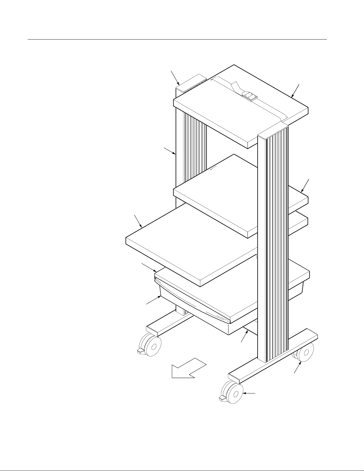
Introduction
Leg Cap
Half Shelf
Leg Assembly
Half Shelf
Keyboard Shelf
Drawer Shelf
Drawer
Strut
Non-Locking Caster
Front
Locking Caster
Figure 2: The K475 Workstation Tower
4
K475 Workstation Tower Instructions
Page 13

Base Assembly
Begin assembling the cart by joining the leg assemblies using the strut, and then
putting on the casters. You will use these parts:
H 2 Locking Casters
H 2Non-LockingCasters
H 2 Extrusions
H 2Legs
H 4 Bumpons
H 4 1/4--20 x 1-1/4 inch Screws
H 4 1 inch Fender Washers
H 13/16AllenWrench
H 41x3inchEndCaps
H 1Strut
H 4 1/2 inch Split Lockwashers
H 4 1/4--20 Button Head Screws, 1/2 inch length
H 4 1/4 inch Tooth Lockwashers
H 4 Short Rails
You will use a 3/4 inch (19 mm) wrench or adjustable wrench, and the 3/16 inch
Allen wrench included with your tower.
1. Prepare the strut as shown in Figure 3. P osition the short rail with the raised
threaded flange toward the strut. Leave each screw assembly loose; do not
screw the short rail onto the button head screw more than one full turn.
K475 Workstation Tower Instructions
5
Page 14
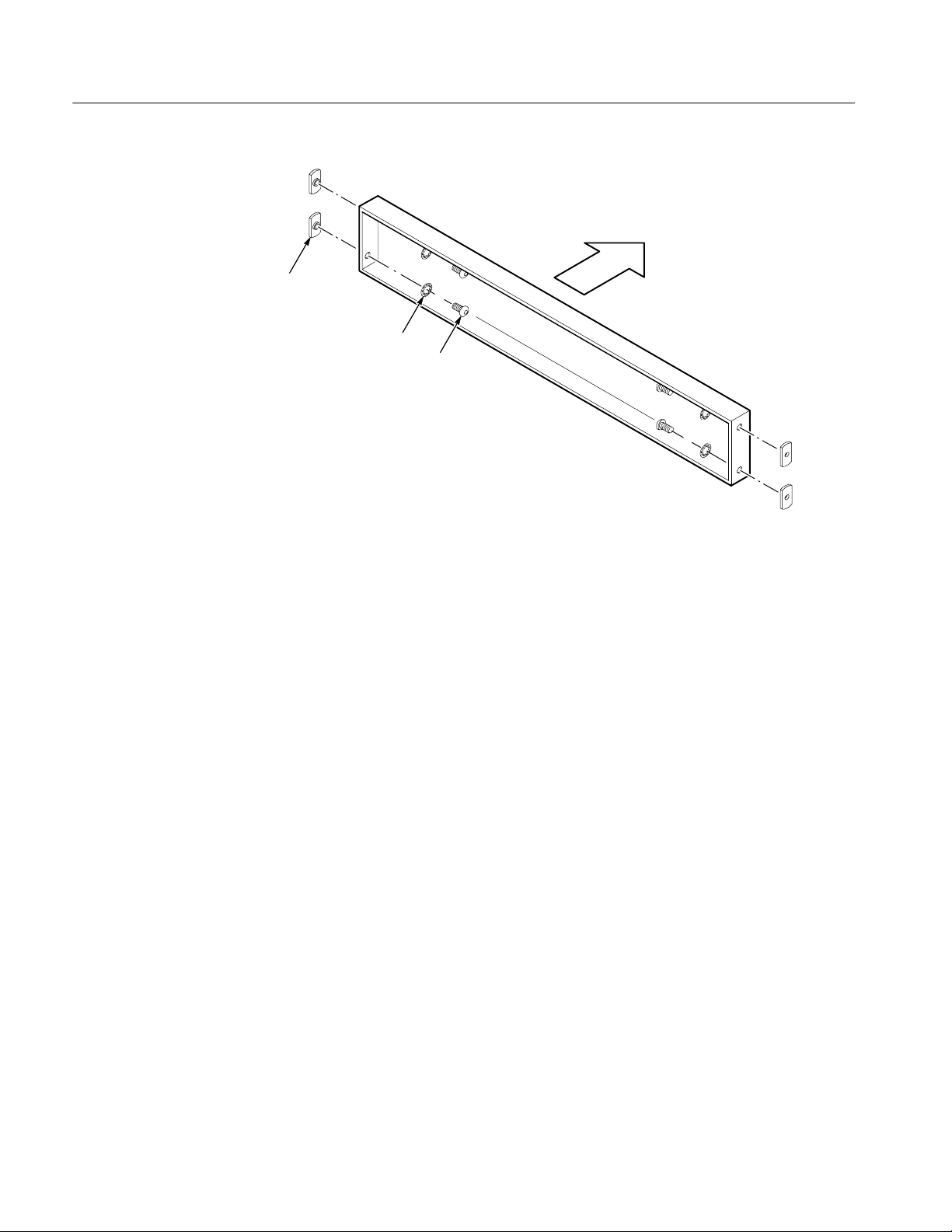
Base Assembly
Front
Short Rail
1/4 inch Tooth Lockwasher
1/4--20 Button Head Screw
Figure 3: Preparing the Strut for Base Assembly
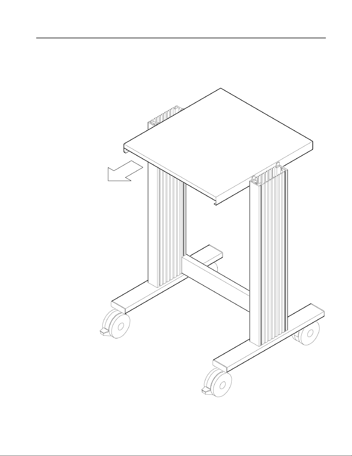
2. On each leg assembly, observe that there is a small, clear, plastic button on
the horizontal leg bar. This button is on the inside of the tower, at the back.
Position the leg assemblies as shown in Figure 4. Leave a space between the
leg assemblies about equal to the length of the strut.
6
K475 Workstation Tower Instructions
Page 15

Base Assembly
Pencil Marks: first line should be 10 inches
from the bottom of the extrusion. For the first
leg assembly, turn extrusion so pencil marks
are on the inside. For second leg assembly,
pencil marks are also on the inside.
Bumpons are on the
inside of the extrusions.
Clear Plastic Buttons (1 on each leg assembly)
Note: Leg tube can be crushed if screw is over
tightened; maximum torque is 3-6 foot/pounds.
Figure 4: Aligning the Leg Assemblies and the Strut
3. Orient extrusion so the end with threaded holes is on the bottom If shelf
position pencil marks are present on one of the slotted sides of the extrusion
there should be one mark 10 inches from this end. You will build two leg
assemblies, one with the extrusion oriented with pencil marks on the right
side and the second with pencil marks on the left side.
4. Place extrusion on top of leg tube oriented so the caster nuts are on the
bottom as shown in Figure 4.
K475 Workstation Tower Instructions
7
Page 16

Base Assembly
5. Place long screw through washer and insert through bottom of leg tube (side
with large caster nuts) and into the extrusion. Screw will extend through top
of leg tube to receive threaded ends of extrusion. Hand tighten with hex key.
CAUTION. Leg tube can be crushed if screw is over tightened.
Max torque is 3--6 ft--lbs. Repeat for second assembly, be sure to orient
extrusion so pencil marks are on the other side.
6. Apply two bumpons to the top of each leg as shown in the illustration. They
go on the side of the extrusion with pencil marks for each assembly.
7. Install end caps into end of each leg. Don’t install end caps into extrusions.
8. Position the strut horizontally between the leg assemblies, as shown in
Figure 4, with the open side of the strut to the back. Line up the short rails
with the back groove in the leg assemblies.
9. Slide the strut down to the base of the tower, adjusting the distance between
the leg assemblies as needed. When complete, make sure the strut is resting
tight against the clear plastic buttons on the leg assemblies.
10. Use the 3/16 inch Allen wrench to tighten the button head screws. Tighten
them first snugly, then go back and tighten them firmly.
NOTE. If you have a torque wrench available, tighten these and all shelf screws
to 60 in⋅lb (6.8 N⋅m) torque.
11. Tip the tower onto its back as shown in Figure 5, resting it on the work
surface by the tops and backs of the leg assemblies.
12. Identify which casters are locking and which are non-locking. The locking
casters, which go on the front of the cart, have an extra tab that you step on
to lock the wheels.
8
K475 Workstation Tower Instructions
Page 17

Base Assembly
NonLocking
Casters
Locking
Casters
1/2 inch Split
Lockwashers
Front
Figure 5: Installing the Casters
13. On the locking casters, place a 1/2 inch split lockwasher on each threaded
shaft, then install the casters into the two front holes in the bottoms of the
leg assemblies. Tighten the casters using the wrench only until they are snug.
14. On the non-locking casters, place a 1/2 inch split lockwasher on each
threaded shaft, then install the casters into the two back holes in the bottoms
of the leg assemblies. Tighten the casters using the wrench only until they
are snug.
15. Return the tower to the upright position.
K475 Workstation Tower Instructions
9
Page 18

Drawer Shelf and Drawer
Install a drawer shelf and drawer in the tower. You will use these parts:
H 1DrawerShelf
H 1Drawer
H 4 1/4--20 Cap Head Screws, 1/2 inch length
H 4 1/4 inch Tooth Lockwashers
H 4WeldNuts
H 2 Press-Stud Retainers
You will use the 3/16 inch Allen wrench and the circular bubble level included
with your tower.
1. Prepare the drawer shelf as shown in Figure 6 by installing a cap head screw,
a tooth lockwasher, and a weld nut in each of the four side holes of the shelf.
Leave each screw assembly loose; do not screw the weld nut onto the cap
head screw more than one full turn.
10
Weld Nut
1/4 inch Tooth Lockwasher
1/4--20 Cap Head Screw
Figure 6: Preparing the Drawer Shelf
K475 Workstation Tower Instructions
Page 19

Front
Drawer Shelf and Drawer
2. Position the drawer shelf horizontally between the leg assemblies, as shown
in Figure 7. Position the shelf so the open edge is to the front of the tower.
Figure 7: Aligning the Drawer Shelf
K475 Workstation Tower Instructions
11
Page 20

Drawer Shelf and Drawer
3. Slide the drawer shelf down to into the position shown in Figure 8. (A light
pencil line has been marked on the insides of the leg assemblies at this
position.) Slide the drawer shelf slowly between the leg assemblies to avoid
scratching the paint. Use the circular bubble level to make sure the shelf is
level.
If you have another person helping you, that person can hold the shelf at the
proper height as you tighten the screws. If you are assembling the tower by
yourself, tighten each screw in turn just enough to hold, and then adjust the
heights one by one until the shelf is positioned properly.
4. Use the 3/16 inch Allen wrench to tighten the cap head screws. Tighten them
first snugly, then go back and tighten them firmly.
12
Figure 8: Installing the Drawer
K475 Workstation Tower Instructions
Page 21

Drawer Shelf and Drawer
5. Slide the drawer in underneath the drawer shelf as shown in Figure 8.
Position the drawer so that the curved edge is to the front of the tower. Slide
the drawer into the shelf until it stops.
6. Use your thumb to press into place the two press-stud retainers at the bottom
of the drawer rails, as shown in Figure 9.
Figure 9: Installing the Press-Stud Retainers
K475 Workstation Tower Instructions
Insert Press-Stud Retainer Into
Hole on Bottom of Drawer
Shelf (one each side)
13
Page 22

Keyboard Shelf
Install the keyboard shelf in the tower in the same way that you installed the half
shelf. You will use these parts:
H 1 Keyboard Shelf
H 4 1/4--20 Cap Head Screws, 1/2 inch length
H 4 1/4 inch Tooth Lockwashers
H 4WeldNuts
You will use the 3/16 inch Allen wrench and the circular bubble level included
with your tower.
Position the keyboard shelf with the largest shelf area to the front of the tower.
14
K475 Workstation Tower Instructions
Page 23

Half Shelf
Install a half shelf in the tower. You will use these parts:
H 1HalfShelf
H 4 1/4--20 Cap Head Screws, 1/2 inch length
H 4 1/4 inch Tooth Lockwashers
H 4WeldNuts
You will use the 3/16 inch Allen wrench and the circular bubble level included
with your tower.
1. Prepare the half shelf as shown in Figure 10 by installing a cap head screw, a
tooth lockwasher, and a weld nut in each of the four side holes of the shelf.
Leave each screw assembly loose; do not screw the weld nut onto the button
head screw more than one full turn.
Weld Nut
1/4 inch Tooth Lockwasher
1/4--20 Cap Head Screw
Front
Figure 10: Preparing the Half Shelf
K475 Workstation Tower Instructions
15
Page 24

Half Shelf
2. Position the half shelf horizontally between the leg assemblies, as shown in
Figure 11. The half shelf extends farther back from the leg assemblies than it
protrudes in front.
Front
Figure 11: Aligning the Half Shelf
3. Slide the half shelf down into position. A light pencil line has been marked
on the insides of the leg assemblies at the recommended position. Slide the
half shelf slowly between the leg assemblies to avoid scratching the paint.
Use the circular bubble level to make sure the shelf is level.
If you have another person helping you, that person can hold the half shelf at
the proper height as you tighten the screws. If you are assembling the tower
by yourself, tighten each screw in turn just enough to hold, and then adjust
the heights one by one until the shelf is positioned properly.
4. Use the 3/16 inch Allen wrench to tighten the cap head screws. Tighten them
first snugly, then go back and tighten them firmly.
16
K475 Workstation Tower Instructions
Page 25

Second Half Shelf
Install a second half shelf in the tower in the same way that you installed the first
half shelves. This shelf should be at the height of the leg assemblies. You will
use these parts:
H 1HalfShelf
H 4 1/4--20 Cap Head Screws, 1/2 in length
H 4 1/4 in Tooth Lockwashers
H 4WeldNuts
You will use the 3/16 inch Allen wrench and the circular bubble level included
with your tower.
Position the half shelf so that it extends farther back from the leg assemblies than
it protrudes in front.
K475 Workstation Tower Instructions
17
Page 26

Leg Caps
Install the two leg caps in the tops of the leg assemblies. You do not need any
tools to install the leg caps.
Press a leg cap into the top of each leg assembly as shown in Figure 12. You may
need to press them into place with the heel of your hand.
18
Figure 12: Installing the Leg Caps
K475 Workstation Tower Instructions
Page 27

Nylon Straps
The last assembly step to finish your tower is to install the four Nylon straps
with buckles. You do not need any tools for this step.
Many of the shelves of your tower have slots for installing Nylon straps. Straight
shelves have slots for two straps each, and half shelves have slots for one strap
each. Y ou should install your straps in the shelves you will be using to hold
instruments.
Install the Nylon straps as shown in Figure 13. Note the routing of the strap
through the buckle. This routing allows you to tighten the strap around an
instrument by pulling on the free end of the strap. To loosen a strap, pull up on
the tab of the buckle.
Figure 13: Installing the Nylon Straps with Buckles
K475 Workstation Tower Instructions
19
Page 28

Customization
You can customize your tower in several ways:
H You can adjust the heights of any of the shelves. First remove all equipment
from the cart. Loosen the four screws associated with the shelf (or for tilting
shelves, the shoulder bolts, oval knobs, and set screws), adjust the height,
level, and retighten.
H You can move the Nylon straps to any shelf where they are needed.
H You can apply the press-on probe holder anywhere on the cart that is
convenient. Once applied, it cannot be moved. Make sure the place you are
applying it is clean and dry. Peel the backing from the sticky tape and press
holder into place.
H You can rearrange the configuration of the shelves by disassembling the
tower and reassembling it in a different order. Remember to build the tower
from the bottom, shelf by shelf.
WARNING. Changes in shelf location and loading can affect the balance of the
tower. If you arrange the shelves differently from the configuration described in
this manual, test the tower carefully for stability before using it.
20
K475 Workstation Tower Instructions
Page 29

Specifications
The K475 Workstation Tower meets the specifications in Table 2. Table 3 shows
additional characteristics.
Table 2: Performance Specifications
Parameter Specification
Loading Limit,
Top Shelf
16 kg (35 lb)
Loading Limit,
Middle and Keyboard
Shelves
Loading Limit,
Drawer
34 kg (75 lb)
6.8kg(15lb)
Table 3: Physical Characteristics
Parameter Typical Characteristic
Overall Dimensions
height
width
depth
Half Shelf Dimensions
width
depth
Keyboard Shelf
Dimensions
width
depth
Drawer Shelf Dimensions
width
depth
1.415 m (55.7 in)
635 mm (25.0 in)
762 mm (30.0 in)
508 mm (20.0 in)
419 mm (16.5 in)
508 mm (20.0 in)
676 mm (26.6 in)
508 mm (20.0 in)
533 mm (21.0 in)
Drawer Dimensions
width
depth
K475 Workstation Tower Instructions
496 mm (19.5 in)
559 mm (22.0 in)
21
Page 30

Replaceable Parts
Contact your Tektronix representative to order replacement parts. Within the
United States and Canada, you can call the National Marketing Center toll-free at
1-800-426-2200 (within Oregon, call 503-690-3915).
You can order the following parts to repair the K475 Workstation Tower:
H Locking Caster, Tektronix part number 401-0691-00.
H Non-Locking Caster, Tektronix part number 401-0690-00.
H Nylon Strap with Buckle, Tektronix part number 346-0261-00.
H Package of assorted small hardware and leg caps, Tektronix part number
Table 4: Parts Included with Tektronix Part Number 016-1259-00
Quantity Part Description
2 Leg Caps
2 1/2 inch Split Lockwashers
016-1259-00. Table 4 lists the parts included in this package.
4 Short Rails
2 Long Rails
8 1/4 inch Tooth Lockwashers
8 1/4--20 Button Head Screws, 1/2 inch length
6 1/8 inch thick Kevlar (plastic) Washers
2 Oval Knobs
2 1/4 inch--20 Set Screws
2 3/4 inch Steel Washers
2 1/4--20 Shoulder Bolts, 1/2 inch length
2 Press-Stud Retainers
22
K475 Workstation Tower Instructions
Page 31

目 次
安全に ご使用い た だ く ために . . . . . . . . . . . . . . . . . . . . . . . . . . . . . . . . . . . 24
Tektronix 連絡先 . . . . . . . . . . . . . . . . . . . . . . . . . . . . . . . . . . . . . . . . . . . . . . 25
はじめに . . . . . . . . . . . . . . . . . . . . . . . . . . . . . . . . . . . . . . . . . . . . . . . . . . . 27
ベース部の組み立て . . . . . . . . . . . . . . . . . . . . . . . . . . . . . . . . . . . . . . . . . . 31
引き出し と棚板 . . . . . . . . . . . . . . . . . . . . . . . . . . . . . . . . . . . . . . . . . . . . . . 36
キーボー ド 用棚板 . . . . . . . . . . . . . . . . . . . . . . . . . . . . . . . . . . . . . . . . . . . . 40
ハーフサイズ棚板 . . . . . . . . . . . . . . . . . . . . . . . . . . . . . . . . . . . . . . . . . . . . 41
ハーフサイズ棚板 (2 枚目) . . . . . . . . . . . . . . . . . . . . . . . . . . . . . . . . . . . . . 43
脚部用キ ャ ッ プ . . . . . . . . . . . . . . . . . . . . . . . . . . . . . . . . . . . . . . . . . . . . . . 44
ナイロン ・ ス ト ラ ップ . . . . . . . . . . . . . . . . . . . . . . . . . . . . . . . . . . . . . . . . 45
カストマイズ . . . . . . . . . . . . . . . . . . . . . . . . . . . . . . . . . . . . . . . . . . . . . . . 46
仕 様 . . . . . . . . . . . . . . . . . . . . . . . . . . . . . . . . . . . . . . . . . . . . . . . . . . . . 47
交換用部品リ ス ト . . . . . . . . . . . . . . . . . . . . . . . . . . . . . . . . . . . . . . . . . . . . 48
K475 型インス ト ラ クシ ョ ン 23
Page 32

安全にご使用いただ く ために
安全に ご 使用いただ く ために、 K475 型台車を ご使用にな る 前に、 次の事
項を必ずお読み く だ さ い。
水平を保つ
K475 型台車は、 常に水平 を 保ち、 特に機器を搭載 し て い る 状態では、 十
分に注意 し て く だ さ い。 台車は安定 し た設計が図 ら れて い ま すが、 極端
に傾け る と 倒れ る可能性があ り ます。 以下の よ う な場合には注意が必要
です。
水平ではな い場所で台車を移動す る場合
出入 り 口等の水平ではな い敷居を通 る場合
ケーブルの上を通過させる場合
傾斜面で台車を移動 さ せ る場合
天板使用時の注意
棚の搭載質量を守る
電気的安全性
台車のカ ス ト マ イ ズ
下部の棚板が空の状態で天板に機器を載せないで く だ さ い。 天板が重 く
な る と 台車が倒れやす く な り ます。 下部の棚板に器材が載っ てい る状態
で天板を使用し て く だ さ い。
本マ ニ ュ アルの仕様欄で規定 さ れてい る質量を超え る も の を 台車の棚に
載せな いで く だ さ い。 天板にはな く べ く 均等に も のを置 く よ う に し て く
ださい。
台車の構成部品は、 外見上非導電物に見え て も 、 すべて導電する も の と
して取り扱ってください。 キャスタを台車と床の絶縁替りに使用しない
で く だ さ い。 また、 キ ャ ス タ を利用 し て接地 し ないで く だ さ い。
棚板や引き 出 し の位置を変え る と 台車のバ ラ ン ス に影響す る こ と が あ り
ます。 本マニュアルで説明されている位置と異なる位置に棚板を取り付
け る場合は、 安定性を十分確認 し て か ら 使用し て く だ さ い。
24 K475 型インス ト ラクシ ョ ン
Page 33

Tektronix 連絡先
電話番号
住 所
ウェブ・サイト
セールス ・ サポー ト
サービ ス ・ サポー ト
テクニカル・ サポート
1-800-833-9200*
Tektronix, Inc.
部署名(担当部署がわかる場合)
14200 SW Karl Braun Drive
P.O.Box 500
Beaverton, OR97077
USA
www.tektronix.com
1-800-833-9200、オプション 1 を選択 *
1-800-833-9200、オプション 2 を選択 *
電子メール:techsupport@tektronix.com
1-800-833-9200、オプション 3 を選択 *
6:00 a.m. ~ 5:00 p.m. 太平洋標準時
* この番号は、北米におけるトールフリー・ダイヤルです。営業時間外
の場合は、ボイス・メールにメッセージを録音してください。
北米以外からの場合は、Tektronix の営業所または代理店にお問い合
わせください。営業所のリストについては、Tektronix のウェブ・サ
イトを参照してください。
K475 型インス ト ラ クシ ョ ン 25
Page 34

Tektronix 連絡先
26 K475 型インス ト ラクシ ョ ン
Page 35

はじめに
ツール
このマニュアルでは、 K475 型台車の組み立て方およ びそ の使用方法を説
明します。
K475 型台車は、 一人で組み立て ら れま すが、 組み立て を補助す る人がい
るとより簡単に作業が行えます。
台車の組み立て には、 水平で十分な広 さ を も つ作業場所が必要です。
カーペ ッ ト 敷き で、 各種の組み立てパーツ を楽に動かせる スペース が理
想です。
台車の組み立て には、 19 mm (3/4 インチ) オープンエン ド ・ レ ンチ、 ま た
はサ イ ズ調整可能な レ ン チが必要です。
他に必要なツールは、 K475 型台車に付属 し てい ます。 付属す る ツ ール
は、 3/16 イ ンチの六角レ ン チおよ び水準器です。
パーツの確認
K475 型台車を構成す る主要部品は個別に梱包 さ れて ダ ン ボール箱に収容
されています。細かいパーツは袋にまとめてあります。付属するツール
も袋に入っています。 28 ページの図 1 は、 組み立てで使用す る 細かい
パーツ を示 し ます。
29 ページの表 1 は、 台車の組み立てに必要なすべてのパーツ を リ ス ト し
ています。
K475 型インス ト ラ クシ ョ ン 27
Page 36

はじめに
ショート
レール
水準器
プレスオン・プローブ・ホルダ
1/2 インチ スプ リ ッ ト ・ロッ クワッ シャ
1/4 インチ ロックワッシャ
1/4 – 20 ボタンヘッ ド型ネジ
1/2 インチ長
3/16 インチ 六角レ ン チ
図 1: 小さいパーツの確認
28 K475 型インス ト ラクシ ョ ン
Page 37

表 1: パーツ ・ リ ス ト
数 量 説 明
大きいパーツ
2
2
2
1
1
1
1
2
2
4
小 さ いパーツ (袋入 り )
4
20
20
20
1
取付工具 (袋入 り )
1
1
キ ャ ス タ (ロ ッ ク 機能付)
キャスタ
棚板 (ハー フ ・ サ イ ズ)
引出 し 用棚板
引出 し
キーボード 用棚板
ス ト ラ ッ ト (支柱)
脚部ア セン ブ リ
キャップ
ナイロン ・ ス ト ラ ップ
1/2 インチ スプリ ッ ト ・ ロ ッ クワッシャ
1/4-20 キャップヘッ ド型ネジ、 1/2 インチ長
1/4 インチ ロ ッ クワッシャ
ナッ ト
プレスオン ・ プローブ ・ ホルダ
3/16 インチ 六角レンチ
水準器
はじめに
K475 型インス ト ラ クシ ョ ン 29
Page 38

はじめに
キャップ
キーボー ド 用
棚板
ハーフサイズ
天板
脚部
ハーフサイズ
棚板
引出し 用
棚板
引出し
図 2: K475 型台車
ストラッ ト
キャスタ
前方向
キャスタ(ロッ ク付)
30 K475 型インス ト ラクシ ョ ン
Page 39

ベース部の組み立て
組み立て の最初の手順は、 ス ト ラ ッ ト (支柱) を使っ て台車の脚部 を連
結し ま す。 次に、 キャ ス タ を取 り 付け ます。 次のパーツ を 使用 し ます。
ロック機能付キャスタ 2 個
キャスタ (ロッ ク機能なし) 2 個
支柱 2 個
脚部 2 個
バンプオン (プラ スチッ クのボタン) 4 個
1/4-20 x 1-1/4 インチ ネジ 4 個
1 インチ フェンダ・ ワッシャ 4 個
3/16 六角レ ンチ (Hex Key) 1 個
1 x 3 インチ エンド ・ キャップ 4 個
ストラット 1 個
1/2 インチ スプリ ッ ト ・ ロックワッシャ 4 個
1/4-20 ボタンヘッド型ネジ、 1/2 インチ長 4 個
1/4 インチ ロックワッシャ 4 個
ショート ・レール 4 個
3/4 インチ (19 mm) レ ンチ と 台車付属の 3/16 イ ンチの六角 レ ンチ を 使用
します。
1. 図 3 に示すようにストラットを準備します。ストラットに対してナッ
トを図に示す位置に固定します。ネジは固く締めずにゆるめにしてお
きます。ナットを1回転以上締めないでください。
K475 型インス ト ラ クシ ョ ン 31
Page 40

ベー ス部の組み立て
前方向
ショートレール
1/4 インチ ロックワッシャ
1/4-20 ボタンヘッ ド型ネジ
図 3: ス ト ラ ッ ト の準備
2. 脚部アセンブリの水平バーに小さいプラスチックのボタンがついてい
ることを確認します。このボタンが台車の後部方向内側になります。
図 4 に示すように、脚部アセンブリを置きます。脚部アセンブリ間の
スペースがストラットの長さにほぼ等しい程度にしておきます。
32 K475 型インス ト ラクシ ョ ン
Page 41

バンプオ
ストラッ ト
ベー ス部の組み立て
ン
脚部の下から約 10 イ ン チの箇所
に鉛筆でマーキン グ し てあ り ます。
脚部の組立て時には鉛筆マー ク が
内側に く る よ う に直立材を配置
します。
接合用溝
直立材
前方向
バンプオン
(内側)
キャップ
透明な プ ラ ス チ ッ ク のボ タ ン
脚
1” フェンダ・ワッシャ
1/4-20 x 1 1/4” キャプヘッ ド型ネジ
注:ネ ジ を き つ く 締めす ぎ な い よ う に し ます。
最大 ト ルク : 3 – 6 フート / ポン ド
図 4: 脚部ア セン ブ リ と ス ト ラ ッ ト の調整
3. ネ ジ取付用の穴のあ る 方を下に向けて縦方向の支柱を置 き ま す。 鉛筆
で薄 く マーキ ング し てあ る方が支柱の内側にな る よ う にし ます。 脚部
アセンブ リ を 2 本組み立て ます。
4. 図 4 に示すように、脚の上に支柱を置き、 キャ ス タ取付部が下に向 く
ようにします。
K475 型インス ト ラ クシ ョ ン 33
Page 42

ベー ス部の組み立て
5. 長いネジに ワ ッ シ ャ を通 し、 脚の部分の下から ネジを通し ます (キ ャ
ス タ取付部分の横にネジ取付穴が あ り ま す)。 取付ネ ジは脚を貫通 し
て支柱と連結させます。 六角レンチでネジを締めます。
注意 : ネジ を きつ く 締めすぎ る と 脚部が破損する 恐れが あ り ま す。
最大 ト ル ク 3-6 ft-lbs で締めます。 2 本目の支柱も同様に組み立て ま
す。
6. 図に示すよ う に、 両方の脚にバン プオ ン を 2 つずつ置 き ま す。 両支柱
の内側にバン プオン を配置 し ます。
7. エン ド ・ キャ ップを脚部に取り付けます。
8. 図 4 に示すよ う に、 脚部アセ ンブ リ の間に ス ト ラ ッ ト を水平に取 り 付
けます。 ス ト ラ ッ ト の開いてい る方が後部に向き ます。 シ ョ ー ト レー
ルを脚部アセンブ リ の後部側の接合用の溝に合わせま す。
9. 脚部アセンブリ間の間隔を調整しながら、ストラットを台車のベース
(基底部)方向にスライドさせます。最後までスライドさせると、ス
トラットが脚部アセンブリのプラスチックのボタンの位置にきっちり
と収まります。
10. 3/16 イ ン チの六角レ ン チ を使用して、ボタンヘッド型ネジを締めま
す。最初は軽く締め、次に固く締めます。
注: ト ル ク ・ レ ン チをお持ちの場合、 棚板のス ク リ ューは 60 in ⋅ lb
(6.8 N ⋅ m) トルクで締めてください。
11. 図 5 に示す よ う に台車を倒 し ます。 脚部の両端に キ ャ ス タ を取 り 付け
ら れる よ う に台車を置 き ま す。
12. ロック機能付と機能なしのキャスタを区別しておきます。 ロック機能
付のキ ャ ス タ は、 台車の前部方向に取 り 付け ら れ、 車輪を ロ ッ ク する
ためのタブが付いています。
34 K475 型インス ト ラクシ ョ ン
Page 43

ベー ス部の組み立て
キャスタ(ロッ ク付)
キャスタ
前方向
1/2 インチ
スプリ ッ ト
ロックワッシャ
図 5: キャスタの取り付け
13. ロック機能付キャスタに、 それぞれ1/2 インチのスプリ ッ ト ・ ロッ ク
ワ ッシャを通し、 脚部アセンブ リ の前部にある穴に取り付けます。
キャスタをレンチで締めます。
14. ロック機能なしのキャスタに、1/2 インチのスプリ ッ ト ・ ロックワッ
シ ャ を 通し 、 脚部アセ ンブ リ の後部にあ る 穴に取 り 付け ます。 キ ャ ス
タをレンチで締めます。
15. 台車を元の状態に戻 し ま す。
K475 型インス ト ラ クシ ョ ン 35
Page 44

引き出し と棚板
ここでは、台車に棚板と引き出しを取り付けます。次のパーツを使用し
ます。
棚板 1 個
引き出し 1 個
1/4-20 キャップヘッ ド型ネジ、 1/2 インチ長 4 個
1/4 インチ ロックワッシャ 4 個
ナッ ト 4 個
プレス ス タ ッ ド ・ リ テイナ 2 個
台車付属の 3/16 イ ンチの六角レ ンチ と 水準器を使用し ま す。
1. 図 6 に示すように棚板を準備します。棚板の両側面の 4 つの穴に、取付
ネジ、ロックワッシャ、ナットを図に示すように取り付けます。スク
リューは固く締めずにゆるめにしておきます。ナットを1回転以上締
めないでください。
ナッ ト
1//4 インチ ロックワッシャ
1/4-20 キャ ッ プヘッ ド型ネジ
図 6: 棚板の準備
36 K475 型インス ト ラクシ ョ ン
Page 45
引き出し と棚板
2. 図 7 に示すように、脚部アセンブリ間で、棚板を水平に位置決めしま
す。棚板の端がオープンになっている方を台車の前方向に向けます。
前方向
図 7: 棚板の位置決め
K475 型インス ト ラ クシ ョ ン 37
Page 46

引き出し と棚板
3. 図 8 に示す位置まで棚板を下にス ラ イ ド させます (棚板を止める位置
は、 脚部アセ ンブ リ の内側に薄 く マーキ ン グ し て あ り ます)。 棚板 を
ス ラ イ ド さ せ る と き に、 塗装を傷つけない よ う に、 ゆっ く り と お ろ し
てい き ま す。 水準器を使っ て、 棚板が水平で あ る こ と を確認 し ます。
他に補助作業員がい る場合は、 補助作業員が棚板を適切な高 さ に保っ
てい る間に、 ネジ を締めま す。 単独で台車を組み立ててい る 場合は、
両側のネジ を交互に締めてい き、 次に高 さ が適切にな る よ う に調整 し
ます。
4. 3/16 イ ンチの六角 レ ンチ を使用して、キャップヘッド型ネジを締めま
す。最初は軽く締め、次に固く締めます。
図 8: 引出 し の取 り 付け
38 K475 型インス ト ラクシ ョ ン
Page 47

引き出し と棚板
5. 図8に示すよ う に、 引出し を棚板の下に ス ラ イ ド さ せます。 引出 し の
端が丸み を帯びた方が台車の前方向に な り ます。 引出し が止ま る ま で
棚板の下に ス ラ イ ド さ せ ま す。
6. 親指を使っ て、 プ レ ス ス タ ッ ド ・ リ テ イ ナ を引き 出し の レールの下に
押し込みます。 図 9 参照。
プレススタッ ド・リテイナを
引出 し の下の穴に差 し込みます。
(両側に 1 個ずつ)
図 9: プ レ ス ス タ ッ ド ・ リ テ イ ナの取 り 付け
K475 型インス ト ラ クシ ョ ン 39
Page 48

キーボー ド 用棚板
ハーフサ イ ズの棚板を取 り 付け る の と 同 じ手順で キーボー ド 用の棚板を
取り付けます。 次のパーツを使用します。
キーボー ド 用棚板 1 個
1/4-20 キャップヘッ ド型ネジ、 1/2 インチ長 4 個
1/4 インチ ロックワッシャ 4 個
ナッ ト 4 個
台車付属の 3/16 イ ンチの六角レ ンチ、 お よ び水準器を使用 し ま す。
キーボー ド 用棚板の面が広い方が前を向 く よ う に配置し ます。
40 K475 型インス ト ラクシ ョ ン
Page 49

ハーフサイズ棚板
ハーフサイズの棚板を取り付けます。 次のパーツを使用し ます。
ハーフサ イ ズ棚板 1 個
1/4-20 キャップヘッ ド型ネジ、 1/2 インチ長 4 個
1/4 インチ ロックワッシャ 4 個
ナッ ト 4 個
台車付属の 3/16 イ ンチの六角レ ンチ、 お よ び水準器を使用 し ま す。
1. 図 10 に示すよ う に、 ハーフサ イ ズの棚板を準備 し、 棚板の両側面の 4
つの穴に、ネジ、ロックワッシャ、ナットを図に示すように取り付け
ます。取り付けネジは固く締めずにゆるめにしておきます。ナットを
1回転以上締めないでください。
ナッ ト
1/4 インチ ロックワッシャ
1/4-20 キャ ップヘッ ド型ネジ
前方向
図 10: ハー フサイ ズ棚板の準備
K475 型インス ト ラ クシ ョ ン 41
Page 50

ハーフサイ ズ棚板
2. 図 11 に示す よ う に、 脚部アセ ンブ リ 間で、 棚板を水平に位置決め し ま
す。 ハー フ サ イ ズの棚板は、 前方向に出てい る 部分よ り も 後ろ方向に
大き く張 り出しています。
図 11 : ハー フ サイ ズの棚板の調整
3. 棚板を下にスライドさせます(棚板を止める位置は、脚部アセンブリ
の内側に薄くマーキングしてあります)。棚板をスライドさせるとき
に、塗装を傷つけないように、ゆっくりとおろしていきます。水準器
を使って、棚板が水平であることを確認します。
他に補助作業員がい る場合は、 補助作業員が棚板を適切な高 さ に保っ
てい る間に、 取付ネジ を締め ます。 単独で台車を組み立ててい る 場合
は、 両側の取付ネジ を交互に締めてい き 、 次に高 さ が適切に な る よ う
に調整し ます。
4. 3/16 イ ンチの六角 レ ンチ を使用して、キャップヘッド型ネジを締めま
す。最初は軽く締め、次に固く締めます。
42 K475 型インス ト ラクシ ョ ン
Page 51

ハーフサイズ棚板 (2 枚目)
2 枚目のハーフサ イ ズの棚板は、 1 枚目 と 同 じ手順で取 り 付け ます。 次の
パーツ を使用 し ます。
ハーフサ イ ズ棚板 1 個
1/4-20 キャップヘッ ド型ネジ、 1/2 インチ長 4 個
1/4 インチ ロックワッシャ 4 個
ナッ ト 4 個
台車付属の 3/16 イ ンチの六角レ ンチ、 お よ び水準器を使用 し ま す。
棚板は、 前方向に出ている部分よりも後ろ方向に大きく張り出すように
取り付けます。
K475 型インス ト ラ クシ ョ ン 43
Page 52

脚部用キ ャ ッ プ
脚部ア セン ブ リ の上端に キ ャ ッ プを 取 り 付け ます。 キ ャ ッ プの取 り 付け
には、 付属のツールは必要あ り ません。
図 12 に示すよ う にキ ャ ッ プを押し 込みます。
図 12: キ ャ ッ プの取 り 付け
44 K475 型インス ト ラクシ ョ ン
Page 53

ナイロン ・ ス ト ラ ップ
組み立て の最後の手順は、 2 つのナイ ロ ン ・ ス ト ラ ッ プ を台車に取 り 付
け る こ と です。 こ こ では、 付属の取 り 付け用の ツ ールは必要 と し ません。
台車の天板には、 ナイ ロ ン ・ ス ト ラ ッ プを取 り 付け る ための細長い穴が
設けられています。 大きいサイズの天板ではス ト ラ ッ プを 2 箇所に、
ハーフ ・ サ イ ズの天板では、 ス ト ラ ッ プ を 1 箇所に取 り 付け ま す。 チル
ト式の天板では、 常にスト ラップを使って機器を固定してください。
図 13 に示すよ う にナ イ ロ ン ・ ス ト ラ ッ プ を取 り 付け ます。
図 13: ナイロン ・ スト ラ ップの取り付け
K475 型インス ト ラ クシ ョ ン 45
Page 54

カストマイズ
用途に合わせて、 台車を さ ま ざ ま に カ ス ト マ イ ズ で き ま す。
棚板の高 さ 位置を調節で き ま す。 最初に、 すべて の機器を台車か ら 外
します。 棚板についている 4 つのネジを緩めます。 高さ を調節し、 水
平を保ち、 再度ネジを締めます。
ナイ ロ ン ・ ス ト ラ ッ プは、 どの棚板で も 使用で き ま す。
プレ スオ ン ・ プ ロ ーブ ・ ホルダを台車のどの位置にも 取 り 付け ら れま
す。 一度取 り 付け る と 、 取 り 外し はで き ません。 取 り 付け る 場所が汚
れて いな く て、 かつ乾燥し てい る こ と を確認 し て く だ さ い。 ホルダ取
り付け部の裏当てをはがし、 取り付け位置にホルダを押し付けます。
台車を いっ たん分解 し て、 再度組み立て る こ と に よ り 、 天板お よび棚
板の位置 を再調整する こ と も で き ま す。
警告 : 棚板や引き 出し の位置を変え る と 台車のバ ラ ン ス に影響す る こ と
があ り ます。 本マニ ュ アルで説明 さ れてい る 位置 と 異な る 位置に棚板 を
取 り 付け る 場合は、 安定性を十分確認 し て か ら 使用 し て く だ さ い。
46 K475 型インス ト ラクシ ョ ン
Page 55

仕 様
K475 型台車は表 2 の仕様を満足 し ます。 表 3 は、 機械的仕様を示 し ま
す。
表 2: K475 型仕様
項 目 仕 様
積載質量
天板
積載質量
中間棚およ び
キーボード 用棚板
積載質量
引き出し
16 kg (35 lb)
34 kg (75 lb)
6.8 kg (15 lb)
表 3: K475 型機械的仕様
項 目 標準値
台車寸法
高さ
幅
奥行
ハーフサ イ ズ棚板
幅
奥行
キーボード 用棚板
幅
奥行
引出 し 用棚板
幅
奥行
引き出し
幅
奥行
1.415 m (55.7 in)
635 mm (25.0 in)
762 mm (30.0 in)
508 mm (20.0 in)
419 mm (16.5 in)
508 mm (20.0 in)
676 mm (26.6 in)
508 mm (20.0 in)
533 mm (21.0 in)
496 mm (19.5 in)
559 mm (22.0 in)
K475 型インス ト ラ クシ ョ ン 47
Page 56

交換用部品 リ ス ト
交換用部品の ご注文は、 当社 ま た は販売店ま でご連絡 く だ さ い。
K475 型台車の修理用パーツ と し て以下の も の を購入で き ま す。
ロ ッ ク 機能付キ ャ ス タ 当社部品番号 401-0691-00
キ ャ ス タ ( ロ ッ ク 機能な し ) 当社部品番号 401-0690-00
ナイ ロ ン ・ ス ト ラ ッ プ (バ ッ ク ル付) 当社部品番号 346-0261-00
台車構成小部品パ ッ ケージ 当社部品番号 016-1259-00 構成部品の
詳細は表 4 にリスト されています。
表 4: 016-1259-00 構成部品
数 量 説 明
2
2
4
2
8
8
6
2
2
2
2
2
脚部用キ ャ ッ プ
1/2 インチ スプリ ッ ト ・ ロッ クワッシャ
ショート ・ レール
ロング・ レール
1/4 インチ ロ ッ クワッシャ
1/4-20 ボタンヘッ ド型ネジ、 1/2 インチ長
1/8 インチ厚 Kevlar (プ ラ スチ ッ ク ) ワ ッ シ ャ
楕円型 ノ ブ
1/4-20 取り付けネジ
3/4 インチ スチール・ ワッシャ
1/4-20 ショルダ・ボルト、1/2 インチ長
プレス ス タ ッ ド ・ リ テイナ
48 K475 型インス ト ラクシ ョ ン
 Loading...