

Page 1

Instructions
K420
Bench Cart
070-8845-04
www.tektronix.com
*P070884504*
070884504
Page 2

Copyright © Tektronix. All rights reserved. Licensed software products are owned by Tektronix or its subsidia ries or
suppliers, and are protected by national copyright laws and international treaty provisions.
Tektronix products are covered by U.S. and foreign patents, issued and pending. Informat ion in this publication supercedes
that in all previously published material. Specifications a nd price c hange privileges reserved.
TEKTRONIX and TEK are registered trademarks of Tektronix, Inc.
Contacting Tektronix
Tektronix, Inc.
14200 SW Karl Braun Drive
P.O. Box 500
Beaverton, OR 97077
USA
For product information, sales, service, and technical support:
H In North America, call 1-800-833-9200.
H Worldwide, visit www.tektronix.com to find contacts in your area.
Page 3

WARRANTY
Tektronix warrants that the products that it manufactures and sell s will be free from defects in materials and workmanship
for a period of one (1) year from the date of shipment. If a product proves defective during this warranty period, Tektronix,
at its option, either will repair the defective product without charge for parts and labor, or will provide a replacement in
exchange for the defective product.
In order to obtain service under this warranty, Customer must notify Tektronix of the defect before the expiration of the
warranty period and make suitable arrangements for the performance of servic e. Customer shall be responsible for
packaging and shipping the defective product to the service center designated by Tektronix, with shipping charges prepaid.
Tektronix shall pay for t he re turn of the product to Customer if the shipment is to a location within the country in which the
Tektronix service center is located. Customer shall be responsible for paying all shipping charges, duties, taxes, and any
other charges for products returned to any other locations.
This warranty shall not apply to any defect , fa ilure or damage caused by improper use or improper or inadequate
maintenance and care. Tektronix shall not be obligated to furnish service under this warranty a) to repair damage resulting
from attempts by personnel other than Tektronix representatives to install, repair or service the product; b) to repair
damage resulting from improper use or connection to incompatible equipment; c) to repair any damage or malfunction
caused by the use of non--Tektronix supplies; or d) to service a product that has been modified or integrated with other
products when the effect of such modification or integration increases the time or difficulty of servicing the product.
THIS WARRANTY IS GIVEN BY TEKTRONIX IN LIEU OF ANY OTHER WARRANTIES, EXPRESS OR IMPLIED.
TEKTRONIX AND ITS VENDORS DISCLAIM ANY IMPLIED WARRANTIES OF MERCHANTABILITY OR
FITNESS FOR A PARTICULAR PURPOSE. TEKTRONIX RESPONSIBILITY TO REPAIR OR REPLACE
DEFECTIVE PRODUCTS IS THE SOLE AND EXCLUSIVE REMEDY PROVIDED TO THE CUSTOMER FOR
BREACH OF THIS W ARRANTY. TEKTRONIX AND ITS VENDORS WILL NOT BE LIABLE FOR ANY INDIRECT,
SPECIAL, INCIDENTAL, OR CONSEQUENTIAL DAMAGES IRRESPECTIVE OF WHETHER TEKTRONIX OR THE
VENDOR HAS ADVANCE NOTICE OF THE POSSIBILITY OF SUCH DAMAGES.
Page 4

Page 5

Table of Contents
General Safety Summary ii...................................
Contacting Tektronix iii.............................................
Introduction 1..............................................
Tools 1....................................................
Parts Identification 1........................................
Base Assembly 5............................................
Drawer Shelf and Drawer 11...................................
Tilt Shelf 15.................................................
Leg Caps 20.................................................
Nylon Straps 21..............................................
Customization 22............................................
Replaceable Parts 23..........................................
Specifications 24.............................................
25...................................
List of Figures
Figure 1: Identification of Small Parts 2........................
Figure 2: The K420 Bench Cart 4..............................
Figure 3: Preparing the Strut for Base Assembly 6................
Figure 4: Building Leg Assemblies 7...........................
Figure 4a: Aligning the Leg Assemblies and the Strut 8............
Figure 5: Installing the Casters 9..............................
Figure 6: Preparing the Drawer Shelf 11.........................
Figure 7: Aligning the Drawer Shelf 12..........................
Figure 8: Installing the Drawer 13..............................
Figure 9: Installing the Press--Stud Retainers 14...................
Figure 10: Preparing the Long Rails 15..........................
Figure 11: Long Rail Alignment Marks on the Leg Assemblies 16....
Figure 12: Preparing the Tilt Shelf with Handle 17................
Figure 13: Aligning the Tilt Shelf with Handle 17..................
Figure 14: Installation of Tilt Shelf Knobs 18.....................
Figure 15: Installing the Leg Caps 20............................
Figure 16: Installing the Nylon Straps with Buckles 21.............
K420 Bench Cart Instructions
i
Page 6

General Safety Summary
Observe these safety precautions when using the K420 Bench Cart.
Keep the K420 Level
Keep the K420 level at all times, especially when it is loaded with instruments.
The cart is designed to be very stable, but it can fall over if tilted to extremes.
Observe this precaution especially in these cases:
H When rolling the cart across uneven floors.
H When rolling the cart through doorways with uneven thresholds.
H When lifting the cart wheels over cables.
H When rolling the cart up or down ramps.
Do Not Overload Shelves
Do not put more weight on any cart shelf than is listed in the specifications.
Load the top of the cart evenly.
Observe Electrical Safety
All parts of the cart must be treated as electrical conductors, even if they appear
to be nonconducting. Do not rely on the casters to provide insulation between the
cart and the surface it stands on. Conversely, do not rely on the casters to provide
a conductive ground path for the cart.
T est the Stability of Custom Configurations
Changes in shelf location and loading can affect the balance of the cart. If you
arrange the shelves differently from the configuration described in this manual,
test the cart carefully for stability before using it.
ii
K420 Bench Cart Instructions
Page 7

Preface
Contacting Tektronix
Phone 1-800-833-9200*
Address Tektronix, Inc.
Department or name (if known)
14200 SW Karl Braun Drive
P.O. Box 500
Beaverton, OR 97077
USA
Web site www.tektronix.com
Sales support 1-800-833-9200, select option 1*
Service support 1-800-833-9200, select option 2*
Technical support Email: techsupport@tektronix.com
1-800-833-9200, select option 3*
6:00 a.m. -- 5:00 p.m. Pacific time
* This phone num ber is toll free in North America. After office hours, please leave a
voice mail message.
Outside North America, contact a Tektronix sales office or distributor; see the
Tektronix web site for a list of offices.
K420 Bench Cart Instructions
iii
Page 8

Preface
iv
K420 Bench Cart Instructions
Page 9

Introduction
Tools
The Tektronix K420 Bench Cart requires some assembly. This manual tells how
to assemble and use the cart.
You can assemble the K420 Bench Cart by yourself, but it is easier if you have
another person to help you.
You will need a large flat area to assemble the cart. The area should be level and
large enough to move the various parts into place. A carpeted floor space is ideal.
You will need a 3/4 inch (19 mm) open--end wrench, or an adjustable wrench that
can be adjusted to that size.
Other tools are included with the K420 Bench Cart. These include a 5/32 inch
Allen wrench, a 3/16 Allen wrench, a 1/8 inch Allen wrench, and a circular
bubble level.
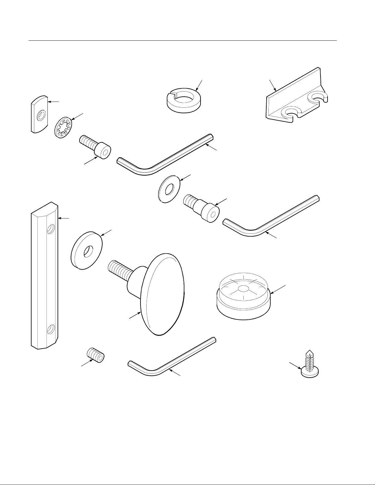
Parts Identification
The large pieces of the K420 Bench Cart are packed separately in the shipping
carton. A bag of small parts is packed in a box with these instructions. The
included tools are also packed in this bag. Figure 1 on page 2 shows the small
parts you will be using.
Table 1 on page 3 lists all the parts needed to assemble the cart, including the
large pieces and assemblies. Take an inventory now to familiarize yourself with
the parts for the assembly process.
K420 Bench Cart Instructions
1
Page 10
Introduction
Weld Nut
1/4-20 CapHead Screw ,
1/2 inchlength
1/4 inch Tooth Lockwasher
1/2 inch Split Lockwasher
3/16 inch AllenWrench
3/4 inch Steel Washer
1/4-20
1/2 inchlength
Press-On
ProbeHolder
ShoulderBolt,
LongRail
1/4-20Set Screw
1/8inch thick Kevlar
(plastic) Washer
5/32 inch AllenW rench
Circular Bubble Level
Oval Knob
Press-Stud Retainer
1/8inchAllenWrench
Figure 1: Identification of Small Parts
2
K420 Bench Cart Instructions
Page 11

Table 1: Parts List
Quantity Desscription
Large Parts
2 Locking Casters
2 Non--Locking Casters
1 Tilt Shelf with handle
1 Drawer Shelf
1 Drawer
1 Strut
2 Leg assemblies
2 Leg Caps
2 Nylon Straps with buckles
Small Parts in Bag
4 1/2 inch Split Lockwashers
Introduction
8 1/4--20 Cap Head Screws, 1/2 inch length
2 1/4--20 Shoulder Bolts, 1/2 inch length
2 Oval Knobs
6 1/8 inch thick Kevlar (plastic) Washers
2 3/4 inch Steel Washers
8 1/4 inch Tooth Lockwashers
10 Weld Nuts
2 Long Rails
2 1/4--20 Set Screws
2 Press--Stud Retainers
1 Press--On Probe Holder
Small Tools in Bag
1 3/16 inch Allen Wrench
1 5/32 inch Allen Wrench
1 1/8 inch Allen Wrench
1 Circular Bubble Level
K420 Bench Cart Instructions
3
Page 12
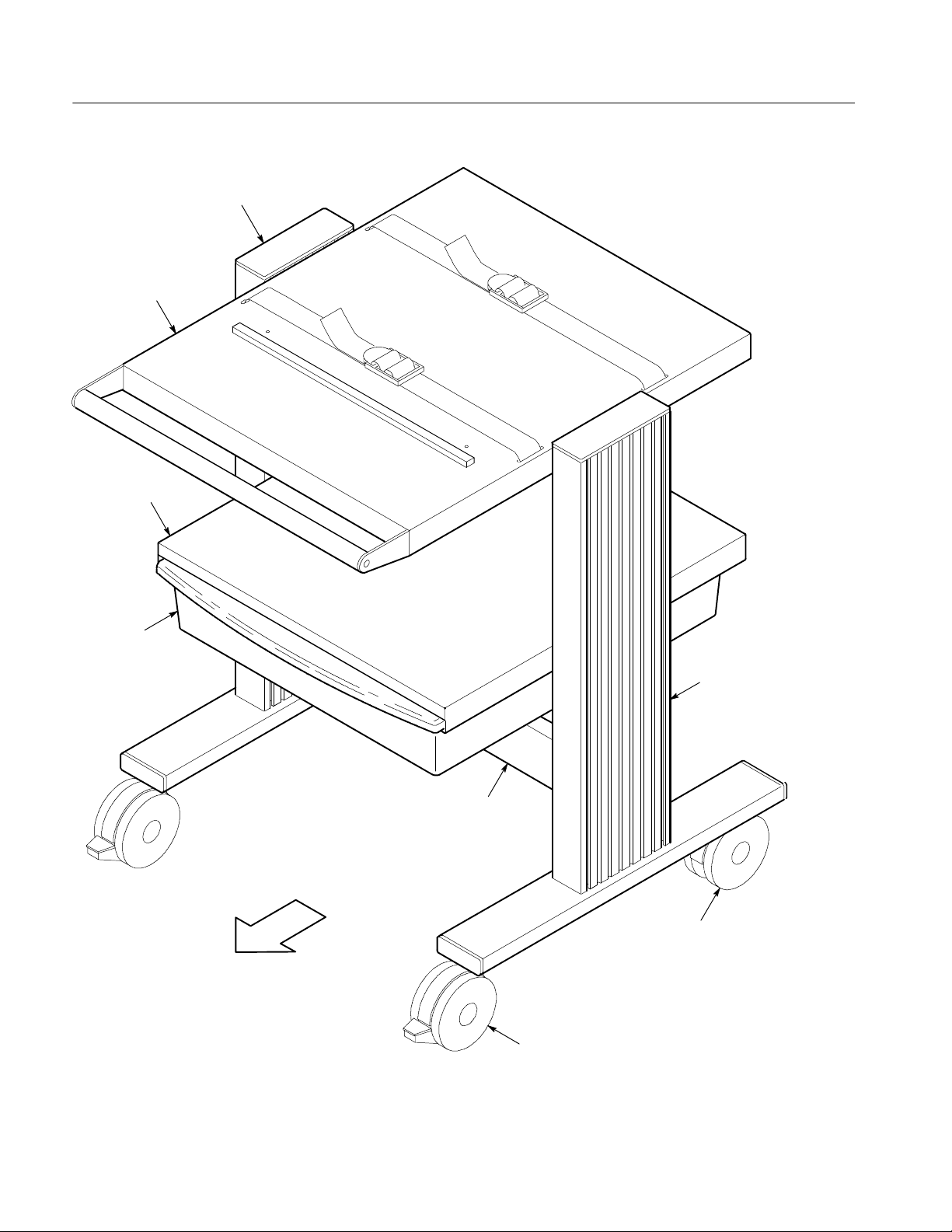
Introduction
Tilt Shelf with handle
Drawer Shelf
Leg Cap
Drawer
Leg Assembly
Strut
Non-Locking Caster
Front
Locking Caster
Figure 2: The K420 Bench Cart
4
K420 Bench Cart Instructions
Page 13

Base Assembly
Begin assembling the cart by joining the leg assemblies using the strut, and then
putting on the casters. You will use these parts:
H 2 Locking Casters
H 2Non--LockingCasters
H 2 Extrusions
H 2Legs
H 4 Bumpons
H 41/4--20x2inchScrews
H 4 1 inch Fender Washers
H 13/16HexKey
H 41x3inchEndCaps
H 1Strut
H 4 1/2 inch Split Lockwashers
H 4 1/4 20 Cap Head Screws, 1/2 inch length
H 4 1/4 inch Tooth Lockwashers
H 4WeldNuts
You will use a 3/4 inch (19 mm) wrench or adjustable wrench, and the 3/16 inch
Allen wrench included with your cart.
1. Prepare the strut as shown in Figure 3. Position the weld nut with the raised
threaded flange toward the strut. Leave each screw assembly loose; do not
screw the weld nut onto the cap head screw more than one full turn.
K420 Bench Cart Instructions
5
Page 14

Base Assembly
Front
WeldNut
1/4 inch Tooth Lockwasher
1/4-20 Cap Head Screw
Figure 3: Preparing the Strut for Base Assembly
2. On each leg assembly, observe that there is a small, clear, plastic button
(bumpon) on the horizontal leg bar. This button is on the inside of the cart, at
the back. Position the leg assemblies as shown in Figure 4. Leave a space
between the leg assemblies about equal to the length of the strut.
6
K420 Bench Cart Instructions
Page 15
Base Assembly
K420 Bench Cart Instructions
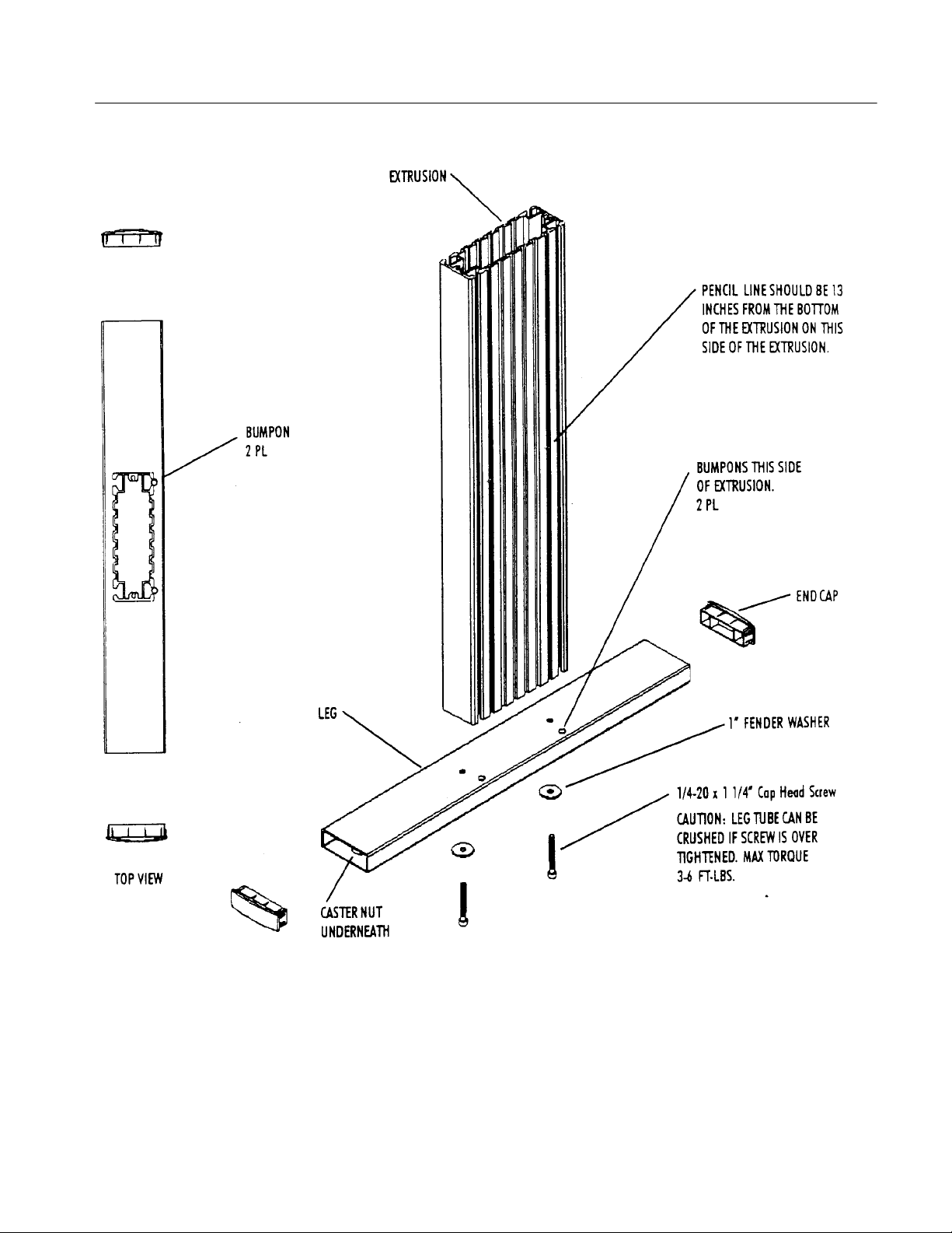
Figure 4: Building Leg Assemblies
3. Orient extrusion so the end with threaded holes is on the bottom If shelf
position pencil marks are present on one of the slotted sides of the extrusion
there should be one mark 13 inches from this end. You will build two leg
assemblies.
7
Page 16

Base Assembly
4. Place long screw through washer and insert through bottom of leg tube (side
with large caster nuts) and into the extrusion. Screw will extend through top
of leg tube to receive threaded ends of extrusion. Hand tighten with hex key.
CAUTION. Leg tube can be crushed if screw is over tightened.
Max torque is 3--6 ft--lbs. Repeat for second assembly.
5. Apply two bumpons to the top of each leg as shown in the illustration. They
go on the side of the extrusion with pencil marks for each assembly.
6. Install end caps into end of each leg. Don’t install end caps into extrusions.
7. Position the strut horizontally between the leg assemblies, as shown in
Figure 4a, with the open side of the strut to the back. Line up the weld nuts
with the back groove in the leg assemblies.
Clearplastic buttons
(oneon each leg assembly)
Front
Figure 4a: Aligning the Leg Assemblies and the Strut
8
K420 Bench Cart Instructions
Page 17

Base Assembly
8. Slide the strut down to the base of the cart, adjusting the distance between
the leg assemblies as needed. When complete, make sure the strut is resting
tight against the clear plastic buttons on the leg assemblies.
9. Use the 3/16 inch Allen wrench to tighten the cap head screws. Tighten them
first snugly, then go back and tighten them firmly.
NOTE. If you have a torque wrench available, tighten these and all shelf screws
to 60 in.... lb (6.8 N.... m) torque.
10. Tip the cart onto its back as shown in Figure 5, resting it on the work surface
by the tops and backs of the leg assemblies.
11. Identify which casters are locking and which are non--locking. The locking
casters, which go on the front of the cart, have an extra tab that you step on
to lock the wheels.
Non-
Locking
Casters
Locking
Casters
1/2 inch Split
Lockwashers
Front
K420 Bench Cart Instructions
Figure 5: Installing the Casters
9
Page 18

Base Assembly
12. On the locking casters, place a 1/2 inch split lockwasher on each threaded
shaft, then install the casters into the two front holes in the bottoms of the
leg assemblies. Tighten the casters only until they are snug using the 3/4
inch (19 mm) wrench.
13. On the non--locking casters, place a 1/2 inch split lockwasher on each
threaded shaft, then install the casters into the two back holes in the bottoms
of the leg assemblies. Tighten the casters only until they are snug.
14. Return the cart to the upright position.
10
K420 Bench Cart Instructions
Page 19

Drawer Shelf and Drawer
Install a drawer shelf and drawer in the cart. Y ou will use these parts:
H 1DrawerShelf
H 1Drawer
H 4 1/4 20 Cap Head Screws, 1/2 inch length
H 4 1/4 inch Tooth Lockwashers
H 4WeldNuts
H 2 Press--Stud Retainers
You will use the 3/16 inch Allen wrench and the circular bubble level included
with your cart.
1. Prepare the drawer shelf as shown in Figure 6 by installing a cap head screw,
a tooth lockwasher, and a weld nut in each of the four side holes of the shelf.
Leave each screw assembly loose; do not screw the weld nut onto the cap
head screw more than one full turn.
Weld Nut
1/4 inch Tooth Lockwasher
1/4-20 Cap Head Screw
Figure 6: Preparing the Drawer Shelf
K420 Bench Cart Instructions
11
Page 20

Drawer Shelf and Drawer
2. Position the drawer shelf horizontally between the leg assemblies, as shown
in Figure 7. Position the shelf so the open edge is to the front of the cart.
Front
12
Figure 7: Aligning the Drawer Shelf
3. Slide the drawer shelf down to into the position shown in Figure 8. (A light
pencil line has been marked on the insides of the leg assemblies at this
position.) Slide the drawer shelf slowly between the leg assemblies to avoid
scratching the paint. Use the circular bubble level to make sure the shelf is
level.
K420 Bench Cart Instructions
Page 21

Drawer Shelf and Drawer
If you have another person helping you, that person can hold the shelf at the
proper height as you tighten the screws. If you are assembling the cart by
yourself, tighten each screw in turn just enough to hold, and then adjust the
heights one by one until the shelf is positioned properly.
4. Use the 3/16 inch Allen wrench to tighten the cap head screws. Tighten them
first snugly, then go back and tighten them firmly.
K420 Bench Cart Instructions
Figure 8: Installing the Drawer
5. Slide the drawer in underneath the drawer shelf as shown in Figure 8.
Position the drawer so that the curved edge is to the front of the cart. Slide
the drawer into the shelf until it stops.
6. Use your thumb to press into place the two press--stud retainers at the bottom
of the drawer rails, as shown in Figure 9.
13
Page 22

Drawer Shelf and Drawer
Figure 9: Installing the Press- Stud Retainers
Insert Press-Stud Retainer Into
Hole on Bottom of Drawer
Shelf (one each side)
14
K420 Bench Cart Instructions
Page 23

Tilt Shelf
Install a tilt shelf with handle in the cart. This shelf should be installed at the
height of the tops of the leg assemblies. You will use these parts:
H 1 Tilt Shelf with Handle
H 2 Long Rails
H 2 1/4 20 Set Screws
H 2WeldNuts
H 2 1/4 20 Shoulder Bolts, 1/2 inch length
H 6 1/8 inch thick Kevlar (plastic) Washers
H 2 3/4 inch Steel Washers
H 2 Oval Knobs
You will use the 5/32 inch and 1/8 inch Allen wrenches and the circular bubble
level included with your cart.
1. Prepare each of the two long rails by installing a set screw in one of the
threaded holes, as shown in Figure 10. Insert the set screw, positioned with
the hexagonal wrench hole out, into the side of the long rail with the bevels.
Do not screw the set screw all the way in to the long rail; only thread it far
enough to get it started.
Figure 10: Preparing the Long Rails
K420 Bench Cart Instructions
15
Page 24

Tilt Shelf
2. Slide one long rail down the front channel each leg assembly with the set
screw at the bottom. Position the long rail so that its top edge is about two
inches below the final tilt shelf height. Figure 11 shows the alignment marks
that you will find on the leg assemblies. Align the tops of the long rails with
these marks. Tighten the set screws using the 1/8 inch Allen wrench.
Alignment Mark
(2 inches below
top of shelf)
Front
Figure 11: Long Rail Alignment Marks on the Leg Assemblies
3. Prepare the tilt shelf with handle as shown in Figure 12, by installing a
shoulder bolt, a steel washer, a Kevlar washer, and a weld nut in each of the
two back holes of the tilt shelf. The front holes are curved slots; use the back
holes opposite them. Place the washer on the outside of the shelf, between
the shelf and the leg assembly. Leave each screw assembly loose; do not
screw the weld nut onto the shoulder bolt more than one full turn.
16
K420 Bench Cart Instructions
Page 25

Weld Nut
3/4 inch Steel Washer
1/8 inch thick Kevlar Washer
1/4-
20 ShoulderBolt
Tilt Shelf
Figure 12: Preparing the Tilt Shelf with Handle
4. Position the tilt shelf with handle horizontally between the leg assemblies, as
shown in Figure 13. Make sure the curved slots under the shelf are toward
the front of the cart.
Front
K420 Bench Cart Instructions
Figure 13: Aligning the Tilt Shelf with Handle
17
Page 26

Tilt Shelf
5. Slide the tilt shelf with handle down to its position at the height of the top of
the leg assemblies. Slide the tilt shelf slowly between the leg assemblies to
avoid scratching the paint.
If you are assembling the cart by yourself, you will find it helpful to tighten
the shoulder bolts on the back of the tilt shelf finger tight. This will hold the
shelf in place as you assemble the front adjustment knobs.
If you have another person helping you, that person can hold the shelf at the
proper height as you perform the following steps.
6. Place a Kevlar washer on the stud of each oval knob. On each side of the tilt
shelf, hold an additional Kevlar washer between the shelf and the leg
assembly and pass the stud of the oval knob through the shelf slot, the
additional washer, and into the top hole of the long rail. Figure 14 shows this
in detail.
1/8 inch thick
Kevlar Washer
Oval Knob
1/8 inch thick Kevlar
Washer inserted between
Leg Assembly and Shelf
Figure 14: Installation of Tilt Shelf Knobs
7. With the adjustment knobs slightly loose, adjust the tilt of the tilt shelf down
as far as possible. The top of each adjustment slot should touch the knob
shaft. Tighten the adjustment knobs hand tight.
18
K420 Bench Cart Instructions
Page 27

Tilt Shelf
8. If you previously tightened the shoulder bolts at the back of the tilt shelf,
loosen them now so that you can adjust the level of the tilt shelf in step 9.
9. Use the circular bubble level to adjust the tilt shelf to be level. When it is
level, use the 5/32 inch Allen wrench to tighten the shoulder bolts at the
back of the tilt shelf.
K420 Bench Cart Instructions
19
Page 28

Leg Caps
Install the two leg caps in the tops of the leg assemblies. You do not need any
tools to install the leg caps.
Press a leg cap into the top of each leg assembly as shown in Figure 15. You may
need to press them into place with the heel of your hand.
20
Figure 15: Installing the Leg Caps
K420 Bench Cart Instructions
Page 29

Nylon Straps
The last assembly step to finish your cart is to install the two Nylon straps with
buckles. You do not need any tools for this step.
Many of the shelves of your cart have slots for installing Nylon straps. Full--size
shelves have slots for two straps each, and half shelves have slots for one strap
each. Y ou should install your straps in the shelves you will be using to hold
instruments. Always use straps to hold equipment on tilting shelves.
Install the Nylon straps as shown in Figure 16. Note the routing of the strap
through the buckle. This routing allows you to tighten the strap around an
instrument by pulling on the free end of the strap. To loosen a strap, pull up on
the tab of the buckle.
K420 Bench Cart Instructions
Figure 16: Installing the Nylon Straps with Buckles
21
Page 30

Customization
You can customize your cart in several ways:
H You can adjust the heights of any of the shelves. First remove all equipment
from the cart. Loosen the four screws associated with the shelf (or for tilting
shelves, the shoulder bolts, oval knobs, and set screws), adjust the height,
level, and retighten.
H You can move the Nylon straps to any shelf where they are needed.
H You can apply the press--on probe holder anywhere on the cart that is
convenient. Once applied, it cannot be moved. Make sure the place you are
applying it is clean and dry. Peel the backing from the sticky tape and press
holder into place.
H Tilting shelves can be tilted by loosening the two oval knobs, tilting the shelf
to the desired position, and retightening the oval knobs.
H Tilting shelves have a retaining bar on the shelf surface; placing instrument
feet in front of this bar helps prevent the instrument from sliding down the
tilted surface. You can move this bar to one of two different positions to
accommodate the instruments you are using.
H You can rearrange the configuration of the shelves by disassembling the cart
and reassembling it in a different order . Remember to build the cart from the
bottom, shelf by shelf.
WARNING. Changes in shelf location and loading can affect the balance of the
cart. If you arrange the shelves differently from the configuration described in
this manual, test the cart carefully for stability before using it.
22
K420 Bench Cart Instructions
Page 31

Replaceable Parts
Contact your Tektronix representative to order replacement parts. Within the
United States and Canada, you can call 1-800-TEK-WIDE (1-800-835-9433).
You can order the following parts to repair the K420 Bench Cart:
H Locking Caster, Tektronix part number 401-0691-00.
H Non--Locking Caster, Tektronix part number 401-0690-00.
H Nylon Strap with Buckle, Tektronix part number 346-0261-00.
H Replacement bar handle with foam cover and set screws, Tektronix part
H Package of assorted small hardware and leg caps, Tektronix part number
Table 2: Parts Included with Tektronix Part Number 016-1259-00
Quantity Part Description
2 Leg Caps
number 367-0452-00.
016-1259-00. Table 2 lists the parts included in this package.
2 1/2 inch Split Lockwashers
4 Weld Nuts
2 Long Rails
8 1/4 inch Tooth Lockwashers
8 1/4 20 Cap Head Screws, 1/2 inch length
6 1/8 inch thick Kevlar (plastic) Washers
2 Oval Knobs
2 1/4inch20SetScrews
2 3/4 inch Steel Washers
2 1/4 20 Shoulder Bolts, 1/2 inch length
2 Press--Stud Retainers
If you intend to mount a TDS/TLA5000 series instrument to cart models K420
or LACART, you will need a mounting bracket kit, Tektronix part number
407-4996-00.
The mounting bracket kit is included when you order TDS5XXX Option 1K
(adds K420 cart and bracket kit). For TLA5000 series instruments you must
order the mounting bracket kit separately (Tektronix part number 407-4996-00).
K420 Bench Cart Instructions
23
Page 32

Specifications
The K420 Bench Cart meets the specifications in Table 3. Table 4 shows
additional characteristics.
Table 3: Performance Specifications
Parameter Specification
Loading Limit,
Shelves 34 kg (75 lb)
Loading Limit,
Drawer 6.8 kg (15 lb)
Shelf Tilt
Top Shelf 0_ to +26_
Table 4: Physical Characteristics
Parameter Typical Characteristic
Overall Dimensions
height 771 mm (30.7 in)
width 635 mm (25.0 in)
depth 620 mm (24.4 in)
Top Shelf Dimensions
width 502 mm (19.8 in)
depth 533 mm (21.0 in)
Drawer Shelf Dimensions
width 508 mm (20.0 in)
depth 533 mm (21.0 in)
Drawer Dimensions
width 496 mm (19.5 in)
depth 559 mm (22.0 in)
24
K420 Bench Cart Instructions
Page 33

目 次
安全に ご使用い た だ く ために . . . . . . . . . . . . . . . . . . . . . . . . . . . . . . . . . . . 26
Tektronix 連絡先 . . . . . . . . . . . . . . . . . . . . . . . . . . . . . . . . . . . . . . . . . . . . . . 27
はじめに . . . . . . . . . . . . . . . . . . . . . . . . . . . . . . . . . . . . . . . . . . . . . . . . . . . 29
ベース部の組み立て . . . . . . . . . . . . . . . . . . . . . . . . . . . . . . . . . . . . . . . . . . 33
引き出し と棚板 . . . . . . . . . . . . . . . . . . . . . . . . . . . . . . . . . . . . . . . . . . . . . . 39
チル ト 式天板 . . . . . . . . . . . . . . . . . . . . . . . . . . . . . . . . . . . . . . . . . . . . . . . 43
脚部用キ ャ ッ プ . . . . . . . . . . . . . . . . . . . . . . . . . . . . . . . . . . . . . . . . . . . . . . 48
ナイロン ・ ス ト ラ ップ . . . . . . . . . . . . . . . . . . . . . . . . . . . . . . . . . . . . . . . . 49
カストマイズ . . . . . . . . . . . . . . . . . . . . . . . . . . . . . . . . . . . . . . . . . . . . . . . 50
交換用部品リ ス ト . . . . . . . . . . . . . . . . . . . . . . . . . . . . . . . . . . . . . . . . . . . . 51
仕 様 . . . . . . . . . . . . . . . . . . . . . . . . . . . . . . . . . . . . . . . . . . . . . . . . . . . . 52
K420 型インス ト ラクシ ョ ン 25
Page 34

安全にご使用いただ く ために
安全に ご 使用いただ く ために、 K420 型台車を ご使用にな る 前に、 次の事
項を必ずお読み く だ さ い。
水平を保つ
K420 型台車は、 常に水平を保ち、 特に機器を搭載 し てい る 状態では、 十
分に注意 し て く だ さ い。 台車は安定 し た設計が図 ら れてい ますが、 極端
に傾け る と 倒れ る 可能性があ り ま す。 以下の よ う な場合には注意が必要
です。
水平ではな い場所で台車を移動す る場合
出入 り 口等の水平ではない敷居を 通 る 場合
ケーブルの上を通過させる場合
傾斜面で台車を移動 さ せ る 場合
棚の搭載質量を守る
電気的安全性
台車のカ ス ト マ イズ
本マ ニ ュ アルの仕様欄で規定 さ れてい る 質量 を超え る も のを台車の棚に
載せな いで く だ さ い。
台車の構成部品は、 外見上非導電物に見え て も 、 すべて導電する も の と
して取り扱ってください。 キャスタを台車と床の絶縁替りに使用しない
で く だ さ い。 ま た、 キ ャ ス タ を利用 し て接地 し ないで く だ さ い。
棚板や引き 出 し の位置を 変え る と 台車のバ ラ ン ス に影響す る こ と があ り
ます。 本マニュアルで説明されている位置と異なる位置に棚板を取り 付
け る 場合は、 安定性を十分確認 し てか ら 使用 し て く だ さ い。
26 K420 型インス ト ラ クシ ョ ン
Page 35

Tektronix 連絡先
Tektronix, Inc.
14200 SW Karl Braum Drive
P.O. Box 500
Beaverton, OR 97077
USA
製品情報、 セ ー ル ス/サ ー ビ ス/テ ク ニ カ ル ・ サ ポ ー ト に ついては、
下記にお問い合わせ く だ さ い。
■北米:1-800-833-9200
■ 世界の他の地域 : Tektronix の営業所 ま た は代理店にお問い合わせ
ください。 営業所のリストについては、 www.tektronix.com を参照
して く ださい。
K420 型インス ト ラクシ ョ ン 27
Page 36

Tektronix 連絡先
28 K420 型インス ト ラ クシ ョ ン
Page 37

はじめに
ツール
このマニュアルでは、 K420 型台車の組み立て方お よ びその使用方法を説
明します。
K420 型台車は、 一人で組み立て ら れ ますが、 組み立て を補助す る人がい
るとより簡単に作業が行えます。
台車の組み立て には、 水平で十分な広 さ を も つ作業場所が必要です。
カーペ ッ ト 敷き で、 各種の組み立てパーツ を楽に動かせ る スペースが理
想です。
台車の組み立て には、 19 mm (3/4 インチ) オープンエン ド ・ レ ンチ、 また
はサ イ ズ調整可能な レ ンチが必要です。
他に必要な ツール (組立工具) は、 K420 型台車に付属し ていま す。 付属
するツールは、 5/32 インチ、 3/16 インチ、 1/8 インチの六角レンチ、およ
び水準器です。
パーツの確認
K420 型台車 を構成す る 主要部品は個別に梱包 さ れて ダ ン ボール箱に収容
されています。細かいパーツは袋にまとめてあります。付属するツール
も袋に入っています。 30 ページの図 1 は、 組み立てで使用す る 細かい
パーツ を示し ます。
31 ページ の表 1 は、 台車の組み立てに必要なすべて のパーツ を リ ス ト し
ています。
K420 型インス ト ラクシ ョ ン 29
Page 38

はじめに
ナッ ト
1/4 インチ ロックワッシャ
1/4 – 20 キャ ップ・ヘッ ド型ネジ
1/2 インチ長
ロングレール
1/2” スプ リ ッ ト・ロッ クワッシャ
1/8 インチ Kevlar
プラスチック・ワッシャ
プレスオン・プローブ・ホルダ
3/16 インチ 六角レ ン チ
3/4 インチ スチール・ワッシャ
1/4 – 20 ショルダ・ボルト
1/2 インチ長
5/32 インチ 六角レ ン チ
水準器
楕円型 ノ ブ
プレススタッ ド・リテイナ
1/4 – 20 取付ネジ
1/8 インチ 六角レ ン チ
図 1: 小さいパーツの確認
30 K420 型インス ト ラ クシ ョ ン
Page 39

表 1: パーツ ・ リ ス ト
数 量 説 明
大きいパーツ
2
2
1
1
1
1
2
2
2
小 さ いパー ツ (袋入 り )
4
8
2
2
6
2
8
10
2
2
2
1
組立工具 (袋入 り )
1
1
1
1
キ ャ ス タ ( ロ ッ ク 機能付)
キャスタ
チル ト 機能付天板 (ハ ン ド ル付)
引出 し 用棚板
引出 し
ス ト ラ ッ ト (支柱)
脚部ア セ ン ブ リ
キャップ
ナイロン ・ ス ト ラ ップ
1/2 インチ スプリ ッ ト ・ ロックワッシャ
1/4-20 キャップヘッド型ネジ、 1/2 インチ長
1/4-20 ショルダ・ボルト、1/2 インチ長
楕円型 ノ ブ
1/8 インチ厚Kevlar (プ ラ スチ ッ ク ) ワ ッ シ ャ
3/4 インチ スチール・ ワッシャ
1/4 インチ ロ ッ クワッシャ
ナッ ト
レール
1/4-20 取り付けネジ
プレス ・ スタ ッ ド ・ リ テイナ
プレスオン ・ プローブ ・ ホルダ
3/16 インチ 六角レンチ
5/32 インチ 六角レンチ
1/8 インチ 六角レンチ
水準器
はじめに
K420 型インス ト ラクシ ョ ン 31
Page 40

はじめに
チル ト 機能付天板
引出し 用棚板
キャップ
引出し
脚部
ストラッ ト
キャスタ
前方向
キャスタ(ロッ ク付)
図 2: K420 型台車
32 K420 型インス ト ラ クシ ョ ン
Page 41

ベース部の組み立て
ス ト ラ ッ ト (横方向の支柱) を使っ て台車の脚部を連結し ます。 次に、
キ ャ ス タ を取 り 付け ま す。 次のパーツ を使用 し ま す。
ロック機能付キャスタ 2 個
キャスタ (ロッ ク機能なし) 2 個
支柱 2 個
脚部 2 個
バンプオン (プラ スチッ クのボタ ン) 4 個
1/4-20 x 2 インチ 取付ネジ 4 個
1 インチ フェンダ・ ワッシャ 4 個
3/16 六角レ ンチ (Hex Key) 1 個
1 x 3 インチ エンド ・ キャップ 4 個
ストラット 1 個
1/2 インチ スプリ ッ ト ・ ロックワッシャ 4 個
1/4-20 キャップヘッド型ネジ、 1/2 インチ長 4 個
1/4 インチ ロックワッシャ 4 個
ナッ ト 4 個
3/4 インチ (19 mm) レ ンチ と 台車付属の 3/16 イ ン チの六角レ ン チを使用
します。
1. 図 3 に示す よ う に ス ト ラ ッ ト を 準備し ま す。 ス ト ラ ッ ト に対 し てナ ッ
ト を図に示す位置に固定し ま す。 ネジは固 く 締めずにゆ る めに し てお
き ま す。 ナ ッ ト を 1 回転以上締め な いで く だ さ い。
K420 型インス ト ラクシ ョ ン 33
Page 42

ベー ス部の組み立て
前方向
ナッ ト
1/4 インチ ロックワッシャ
1/4-20 キャ ッ プヘッ ド型ネジ
図 3: ス ト ラ ッ ト の準備
2. 脚部アセ ンブ リ の水平バーに小 さ いプ ラ ス チ ッ ク のボ タ ン (バ ン プオ
ン) がついている こ と を確認し ます。 こ のボ タ ンが台車の内側にな り
ます。 図 4 に示すよ う に脚部アセンブ リ を置き ます。 脚部アセンブ リ
間のスペースがス ト ラ ッ ト の長 さ にほぼ等しい程度に し ておき ます。
34 K420 型インス ト ラ クシ ョ ン
Page 43

バンプオン (2個)
ベー ス部の組み立て
支柱
脚部の下から約 10 インチの
箇所に鉛筆で マーキ ン グ し て
あ り ます。 脚部の組立て時に
は、 こ のマー ク が内側に く る
ように支柱を配置します。
バン プ オ ン (支柱の
内側に 2 個)
上面図
エンド・キャッ プ
脚部
1” フェンダ・ワッシャ
1/4-20 x 1 1/4” キャプヘッ ド型ネジ
注:ネジをきつく締めすぎない
ようにします。
最大 ト ル ク 3-6 フート/ポンド
キャスタ ・ ナッ ト
(脚部の下側)
図 4: 脚部ア セ ン ブ リ の組立て
3. ネ ジ取付用の穴のあ る方を下に向けて縦方向の支柱を置 き ます。 鉛筆
で薄 く マーキ ング し て あ る方が支柱の内側にな る よ う にし ます。 脚部
アセンブ リ を 2 本組み立て ます。
4. 長いネジにワ ッ シ ャ を通し、 脚の部分の下から ネジ を通 し ます (キ ャ
ス タ取付部分の横にネジ取付穴があ り ま す)。 取付ネジは脚を貫通 し
て支柱と連結させます。 六角レンチでネジを締めます。
K420 型インス ト ラクシ ョ ン 35
Page 44

ベー ス部の組み立て
注意 : ネジ を き つ く 締めすぎ る と 脚部が破損す る恐れがあ り ます。
最大 ト ル ク 3-6 ft-lbs で締めます。 2 本目の支柱も 同様に組み立て ま
す。
5. 図に示すよ う に、 両方の脚にバ ン プオン を 2 つずつ置 き ます。 両支柱
の内側にバン プオン を配置 し ます。
6. エン ド ・ キャ ップを脚部に取り 付けます。
7. 図 4a に示すよ う に、脚部アセ ンブ リ の間にス ト ラ ッ ト を水平に取 り 付
けます。 ス ト ラ ッ ト の開いている方が後部に向き ま す。 ナ ッ ト を脚部
アセンブ リ の後部側の接合用の溝に合わせます。
透明な プ ラ ス チ ッ ク ・
ボタン
前方向
図 4a: 脚部ア セ ン ブ リ と ス ト ラ ッ ト の調整
36 K420 型インス ト ラ クシ ョ ン
Page 45

ベー ス部の組み立て
8. 脚部アセ ンブ リ 間の間隔を 調整 し なが ら 、 ス ト ラ ッ ト を台車のベース
(基底部) 方向に ス ラ イ ド さ せます。 最後 ま で ス ラ イ ド さ せ る と 、 ス
ト ラ ッ ト が脚部アセ ン ブ リ のプ ラ ス チ ッ ク のボ タ ンの位置に き っ ち り
と収まります。
9. 3/16 イ ンチの六角 レ ン チ を使用 し て、 キ ャ ッ プヘ ッ ド 型ネジ を締めま
す。 最初は軽 く 締め、 次に固 く 締め ます。
注: ト ル ク ・ レ ンチ をお持ちの場合、 棚板の ス ク リ ュ ーは 60 in ⋅ lb
(6.8 N ⋅ m) トルクで締めてください。
10. 図 5 に示す よ う に台車を倒 し ます。 脚部の両端にキ ャ ス タ を取 り 付け
ら れる よ う に台車を置 き ます。
11. ロック機能付と機能なしのキャスタを区別しておきます。 ロック機能
付のキ ャ ス タ は、 台車の前部方向に取 り 付け ら れ、 車輪を ロ ッ ク す る
ためのタブが付いています。
キャスタ(ロッ ク付)
キャスタ
前方向
1/2 インチ
スプリ ッ ト
ロックワッシャ
図 5: キャスタの取り付け
K420 型インス ト ラクシ ョ ン 37
Page 46

ベー ス部の組み立て
12. ロック機能付キャスタに、 それぞれ1/2 インチのスプリ ッ ト ・ ロッ ク
ワ ッシャを通し、 脚部アセンブ リ の前部にある穴に取り付けます。
3/4 インチ(19 mm) レンチで締めます。
13. ロック機能なしのキャスタに、1/2 インチのスプリ ッ ト ・ ロックワッ
シ ャ を通 し 、 脚部ア セン ブ リ の後部に あ る 穴に取 り 付け ます。
14. 台車を 元の状態に戻 し ま す。
38 K420 型インス ト ラ クシ ョ ン
Page 47

引き出し と棚板
ここでは、台車に棚板と引き出しを取り付けます。次のパーツを使用し
ます。
棚板 1 個
引き出し 1 個
1/4-20 キャップヘッド型ネジ、 1/2 インチ長 4 個
1/4 インチ ロックワッシャ 4 個
ナッ ト 4 個
プレス ス タ ッ ド ・ リ テイナ 2 個
台車付属の 3/16 イ ンチの六角 レ ンチ と 水準器を 使用し ます。
1. 図 6 に示す よ う に棚板 を 準備し ま す。 棚板の両側面の 4 つの穴に、
キャップヘッ ド型ネジ、 ロックワッシャ、 ナッ ト を図に示すよ うに取
り 付け ます。 ネジは固 く 締めずにゆ る めに し てお き ます。 ナ ッ ト を 1
回転以上締めないで く だ さ い。
ナッ ト
1//4 インチ ロックワッシャ
1/4-20 キャ ッ プヘッ ド型ネジ
図 6: 棚板の準備
K420 型インス ト ラクシ ョ ン 39
Page 48

引き出し と棚板
2. 図 7 に示すように、脚部アセンブリ間で、棚板を水平に位置決めしま
す。 棚板の端がオープンになっ てい る方を台車の前方向に向け ます。
前方向
図 7: 棚板の位置決め
3. 図 8 に示す位置まで棚板を下にス ラ イ ド させます (棚板を止める位置
は、 脚部アセ ンブ リ の内側に薄 く マーキ ン グ し て あ り ま す)。 棚板を
ス ラ イ ド さ せ る と き に、 塗装を 傷つけ ない よ う に、 ゆっ く り と おろ し
てい き ます。 水準器を使 っ て、 棚板が水平であ る こ と を 確認し ま す。
40 K420 型インス ト ラ クシ ョ ン
Page 49

引き出し と棚板
他に補助作業員がい る場合は、 補助作業員が棚板を適切な高 さ に保 っ
てい る間に、 ネジ を締め ます。 単独で台車 を組み立ててい る 場合は、
両側のネジ を交互に締めてい き、 次に高 さ が適切に な る よ う に調整 し
ます。
4. 3/16 イ ンチの六角 レ ン チ を使用 し て、 キ ャ ッ プヘ ッ ド 型ネジ を締めま
す。 最初は軽 く 締め、 次に固 く 締め ます。
図 8: 引出 し の取 り 付け
5. 図 8 に示すよ う に、 引出し を棚板の下に ス ラ イ ド さ せます。 引出し の
端が丸み を帯びた方が台車の前方向に な り ま す。 引出し が止ま る ま で
棚板の下に ス ラ イ ド さ せ ます。
6. 親指を使っ て、 プ レ ス ス タ ッ ド ・ リ テ イ ナを引 き出 し の レールの下に
押し込みます。 図 9 参照。
K420 型インス ト ラクシ ョ ン 41
Page 50

引き出し と棚板
図 9: プ レ ス ス タ ッ ド ・ リ テ イ ナの取 り 付け
プレススタッ ド・リテイナを
引出 し の下の穴に差 し 込み
ます。(両側に 1 個ずつ)
42 K420 型インス ト ラ クシ ョ ン
Page 51

チル ト 式天板
こ こ では、 チル ト 式天板を台車に取 り 付け ま す。 こ の天板は、 脚部ア セ
ンブ リ の上部に取 り 付け ま す。 次のパーツ を 使用し ま す。
チル ト 式天板 (ハン ド ル付) 1 個
レール 2 個
1/4 20 取り付けネジ 2 個
ナッ ト 2 個
1/4-20 ショルダ・ボルト、1/2 インチ長 2 個
1/8 インチ厚 Kevlar (プ ラ スチ ッ ク) ワ ッ シ ャ 6 個
3/4 インチ スチール ・ ワッシャ 4 個
楕円型 ノ ブ 2 個
台車付属の 5/32 インチと 1/8 イ ン チの六角レ ン チ、 お よ び水準器を使用
します。
1. 図 10 に示すよ う に、レールの 2 つの穴の う ちの一方に取 り 付けネジを
装着し ま す。 六角の穴が開いてい る 方を外側に し て、 レールの傾斜の
ついてい る 側にネ ジを 挿入し ま す。 取 り 付けネ ジ を レールの中に完全
には挿入せずに、 少し だけ差 し 込み ます。
図 10: レールの準備
K420 型インス ト ラクシ ョ ン 43
Page 52

チル ト 式天板
2. 取り 付けネジを下にしたレールを脚部アセンブ リ の前方向の溝にス ラ
イ ド させます。 レールの上端がチル ト 式天板の高さ か ら 2 インチ( 約
5 cm) 下の位置にな る よ う に位置決め し ま す。 脚部ア セ ン ブ リ には、
図 11 に示す位置にマーキ ン グ し て あ り ます。 レ ールの上端を こ の
マーキン グ位置に合わせます。 1/8 イ ンチの六角レ ンチを使 っ て取 り
付けネジを締めます。
調整用のマー ク
(天板 ト ッ プ よ り
約 2 インチ下)
図 11: 脚部ア セ ン ブ リ のレ ール位置決め用マーキン グ
3. 図 12 に示すよ う にハン ド ル付天板を準備し、 シ ョ ルダ ・ ボル ト 、 ス
チール ・ ワ ッ シ ャ 、 Kevlar ワ ッ シ ャ と ナ ッ ト をチル ト 式天板の後方の
穴に取 り 付けます。 前方向の穴は天板に傾斜をつけ る ための溝です。
天板 と 脚部ア セ ン ブ リ 間で、 ワ ッ シ ャ を天板の外側に取 り 付け ます。
ネジは軽く 締めておき、 ナッ ト を 1 回転以上締めな いで く だ さ い。
44 K420 型インス ト ラ クシ ョ ン
Page 53

ナッ ト
3/4 インチ スチール
ワッシャ
チル ト 式天板
1/8 インチ厚Kevlar ワッシャ
1/4 – 20 ショルダ・ボルト
図 12: ハ ン ド ル付チル ト 式天板の準備
4. ハン ド ル付チル ト 式天板を、図 13 に示すよ う に脚部アセ ン ブ リ 間に水
平に置き ます。 天板の下にあ る曲線状の溝が台車の前方を向 く よ う に
します。
前方向
図 13: ハ ン ド ル付チル ト 式天板の位置調整
K420 型インス ト ラクシ ョ ン 45
Page 54

チル ト 式天板
5. ハン ド ル付チル ト 式天板を脚部ア セン ブ リ の ト ッ プ位置か ら 下に ス ラ
イ ド させます。 天板をスラ イ ド させる と きに、 塗装を傷つけないよ う
に、 ゆっ く り と おろ し てい き ます。
単独で台車を組み立ててい る 場合は、 チル ト 式天板の後ろ側のシ ョ ル
ダ ・ ボル ト を こ こ で締めておき ま す。 こ う す る と 、 前方の傾斜調整用
ノ ブ を組み立て る 際に天板を支え る こ と がで き ま す。
他に補助作業員がい る場合は、 補助作業員が天板を適切な高 さ に保 っ
てい る間に、 以下の手順を実行し ます。
6. Kevlar ワ ッ シ ャ と 楕円型 ノ ブ を図 14 の よ う に取 り 付け ま す。楕円型 ノ
ブに Kevlar ワッシャを1 個通 し、 天板の傾斜用溝 を通し て、 さ ら に
天板 と 脚部ア セ ン ブ リ 間に も う 1 個の Kevlar ワッシャを使って、
レールの上の穴に取 り 付け ます。 詳細は図 14 を参照して く だ さい。
1/8 インチ厚
Kevlar ワッシャ
楕円型 ノ ブ
1/8 インチ厚Kevlar ワッシャ
を脚部 ア セ ン ブ リ と棚板の
間に挿入し ます。
図 14: チル ト 式天板の ノ ブの取 り 付け
7. 調整 ノ ブを 少 し 緩め、 チル ト 式天板の位置を決め ま す。 傾斜調整用の
溝の ト ッ プ位置に ノ ブの軸が位置す る よ う に し ま す。 調整 ノ ブ を締め
ます。
46 K420 型インス ト ラ クシ ョ ン
Page 55

チル ト 式天板
8. チル ト 式天板の後ろ側の シ ョ ルダ ・ ボル ト をすでに締めてい る場合
は、 こ こ で少し ボル ト を緩め、 次の ス テ ッ プで、 チル ト 式天板が水平
を保っている こ と を確認し ます。
9. 水準器を使用 し て、 チル ト 式天板が水平を保 っ て い る こ と を 確認 し ま
す。 水平を確認後、 5/32 イ ン チの六角 レ ン チ を使っ て、 チル ト 式天板
の後部のシ ョ ルダ ・ ボル ト を締めます。
K420 型インス ト ラクシ ョ ン 47
Page 56

チル ト 式天板
48 K420 型インス ト ラ クシ ョ ン
Page 57

脚部用キ ャ ッ プ
脚部ア セ ン ブ リ の上端にキ ャ ッ プ を取 り 付け ま す。 キ ャ ッ プの取 り 付け
には、 付属のツールは必要あ り ません。
図 15 に示すよ う にキ ャ ッ プを押 し 込みま す。
図 15: キ ャ ッ プの取 り 付け
49 K420 型インス ト ラ クシ ョ ン
Page 58

ナイロン ・ スト ラ ップ
組み立て の最後の手順は、 2 つのナ イ ロ ン ・ ス ト ラ ッ プ を台車に取 り 付
け る こ と です。 こ こ では、 付属の取 り 付け用の ツールは必要 と し ま せん。
台車の天板には、 ナイ ロ ン ・ ス ト ラ ッ プを取 り 付け る ための細長い穴が
設けられています。 大きいサイズの天板ではス ト ラ ッ プを 2 箇所に、
ハーフ ・ サ イ ズの天板では、 ス ト ラ ッ プを 1 箇所に取 り 付け ま す。 チル
ト式の天板では、 常にスト ラップを使って機器を固定してください。
図 16 に示すよ う にナ イ ロ ン ・ ス ト ラ ッ プを取 り 付けます。
図 16: ナイロン ・ スト ラップの取り付け
K420 型インス ト ラクシ ョ ン 50
Page 59

カストマイズ
用途に合わせて、 台車を さ ま ざ ま に カ ス ト マ イ ズで き ま す。
棚板の高 さ 位置を調節で き ま す。 最初に、 すべての機器 を台車か ら 外
します。 棚板についている 4 つのネ ジ を 緩め ます (チル ト 式天板の場
合は、 シ ョ ルダ ・ ボル ト 、 楕円型 ノ ブ、 取付ネ ジ を 緩め ます)。 高 さ
を調節し、水平を保ち、再度ネジを締めます。
ナイ ロ ン ・ ス ト ラ ッ プは、 チル ト 式天板以外に、 他の棚板で も 使用で
きます。
プレ ス オ ン ・ プ ローブ ・ ホルダ を台車のどの位置に も取 り 付け ら れ ま
す。 一度取 り 付け る と 、 取 り 外 し はで き ま せん。 取 り 付け る 場所が汚
れて いな く て、 かつ乾燥 し て い る こ と を 確認し て く だ さ い。 ホルダ取
り付け部の裏当てをはがし、 取り付け位置にホルダを押し付けます。
チル ト 式天板は楕円型 ノ ブ を 緩め る こ と で希望する 位置に角度を変え
ら れます。 角度調整後 ノ ブ を再度締めま す。
チル ト 式天板には リ テ イ ニン グ ・ バーがついてい ます。 機器の脚を こ
のバーの位置に合わせ る こ と に よ り 、 傾斜面か らすべ り 落ち る の を防
ぎます。 こ の リ テ イ ニ ング ・ バーは、 台車に載せる機器に合わせて留
める位置を変えられます。
台車を いっ たん分解し て、 再度組み立て る こ と に よ り 、 天板およ び棚
板の位置 を再調整する こ と も で き ま す。
警告 : 棚板や引き 出し の位置を変え る と 台車のバ ラ ン ス に影響す る こ と
があ り ます。 本マニ ュ アルで説明 さ れてい る 位置 と 異な る 位置に棚板 を
取 り 付け る 場合は、 安定性 を 十分確認 し てか ら 使用 し て く だ さ い。
51 K420 型インス ト ラ クシ ョ ン
Page 60

交換用部品 リ ス ト
交換用部品の ご 注文は、 当社 ま たは販売店 ま で ご連絡 く だ さ い。
K420 型台車の修理用パーツ と し て以下の も の を購入で き ます。
ロ ッ ク 機能付キ ャ ス タ 当社部品番号 401-0691-00
キ ャ ス タ ( ロ ッ ク 機能な し) 当社部品番号 401-0690-00
ナイ ロ ン ・ ス ト ラ ッ プ (バ ッ ク ル付) 当社部品番号 346-0261-00
バー ・ ハ ン ド ル (カ バーお よ び取付ネジ付) 当社部品番号
367-0452-00
台車構成小部品パ ッ ケージ 当社部品番号 016-1259-00 構成部品の
詳細は表 2 にリスト されています。
表 2: 016-1259-00 構成部品
数 量 説 明
2
2
4
2
8
8
6
2
2
2
2
2
脚部用キ ャ ッ プ
1/2 インチ スプリ ッ ト ・ ロックワッシャ
ナッ ト
レール
1/4 インチ ロ ッ クワッシャ
1/4 20 キャップヘッド型ネジ、 1/2 インチ長
1/8 インチ厚 Kevlar (プ ラ スチ ッ ク ) ワ ッ シ ャ
楕円型 ノ ブ
1/4 20 取り付けネジ
3/4 インチ スチール・ ワッシャ
1/4 20 ショルダ・ボルト、1/2 インチ長
プレス ス タ ッ ド ・ リ テイナ
TDS/TLA5000 シリーズをK420 型台車ま た は LACART に取 り 付け る場合
は、 ブ ラ ケ ッ ト ・ キ ッ ト (当社部品番号 407-4996-00)が必要です。
TDS5XXX 型オプシ ョ ン 1K 型をご注文の場合は、 ブ ラ ケ ッ ト ・ キ ッ ト は
標準で含まれ ます。 TLA5000 シリーズの場合は、ブラケット ・キット
(当社部品番号 407-4996-00)を別途ご注文ください。
K420 型インス ト ラクシ ョ ン 52
Page 61

仕 様
K420 型台車は表 3 の仕様を満足 し ま す。 表 4 は、 機械的仕様を示 し ま
す。
表 3: K420 型仕様
項 目 仕 様
積載質量
天板およ び棚板
積載質量
引き出し
チル ト (調整角度)
天板 0°~ +26°
34 kg (75 lb)
6.8 kg (15 lb)
表 4: K420 型機械的仕様
項 目 標準値
台車寸法
高さ
幅
奥行
天板
幅
奥行
棚板
幅
奥行
引き出し
幅
奥行
771 mm (30.7 in)
635 mm (25.0 in)
620 mm (24.4 in)
502 mm (19.8 in)
533 mm (21.0 in)
508 mm (20.0 in)
533 mm (21.0 in)
496 mm (19.5 in)
559 mm (22.0 in)
53 K420 型インス ト ラ クシ ョ ン
Page 62

仕 様
K420 型インス ト ラクシ ョ ン 54
 Loading...